royal arsenal buildings 10, 11 and royal carriage … arsenal buildings 10, 11 and royal carriage...
TRANSCRIPT

ROYAL ARSENALBuildings 10, 11 and Royal Carriage Square Structural Method Statement

Copyright © 1976 - 2016 BuroHappold Engineering. All Rights Reserved.
Buildings 10, 11 and Royal Carriage Square
Structural Method Statement
035308
28 July 2016
Final

Buildings 10, 11 and Royal Carriage Square Revision 00
Structural Method Statement 28 July 2016
Copyright © 1976 - 2016 BuroHappold Engineering. All Rights Reserved Page 3
Revision Description Issued by Date Checked
00 Structural Method Statement OB 28/07/16 AP
O:\035308 Royal Arsenal Riverside Heritage Buildings\F4 Structures\03 Reports\Planning\160727 OB 035308 Structural
Method Statement rev 00d.docx
This report has been prepared for the sole benefit, use and information of Berkeley Homes for the purposes set out in
the report or instructions commissioning it. The liability of Buro Happold Limited in respect of the information contained
in the report will not extend to any third party.
author Oliver Blythe
date 28/07/16
approved Angus Palmer
signature
date 28/07/16
..
Buildings 10, 11 and Royal Carriage Square Revision 00
Structural Method Statement 28 July 2016
Copyright © 1976 - 2016 BuroHappold Engineering. All Rights Reserved Page 5
Contents
1 Introduction 9
2 Existing Buildings – Recent relevant history 10
2.1 Building 10 Royal Carriage Factory 10
2.2 Building 11 Officers' House 10
3 Proposed Works 11
3.1 Building 10 Royal Carriage Factory Proposals 11
3.2 Building 11 Officers' House Proposals 12
4 Structural Methodology 13
4.1 Building 10 Works 13
4.1.1 Partial demolition of northern range 13
4.1.2 Reinstatement of lateral stability elements to B10 external walls 14
4.1.3 Partial removal of roof covering to southern range 15
4.1.4 Refurbishment and repair to existing roof truss structure 15
4.1.5 Repair to existing brick structure 16
4.1.6 New openings to existing brick structure 16
4.1.7 Interface with New build Block 17
4.2 Building 11 Works 18
4.2.1 Minor demolition works 18
4.2.2 Internal structural works 18
4.2.3 New roof structure 19
4.2.4 New build elements 19
4.2.5 New build link structure 19
4.2.6 Crossrail interface 20
Appendix A
Table of Tables N/A
No table of tables entries found
Table of Figures N/A
N/A

Buildings 10, 11 and Royal Carriage Square Revision 00
Structural Method Statement 28 July 2016
Copyright © 1976 - 2016 BuroHappold Engineering. All Rights Reserved Page 9
1 Introduction
The purpose of this report is to describe the notable aspects of the proposed structural works to buildings 10 and 11.
The report will cover works to the existing B10 and B11 building structures, the adjacent new build structures and the
interfaces between.
This report is not intended to set out definitive methodologies for the structural works, as these are expected to be
developed to the satisfaction of all relevant approval parties as part of the subsequent design development process. The
intent is to outline the main features of the works, describe design intent and highlight constraints.
Also refer to the following relevant documents
CONDITION SURVEY REPORT - THE CARRIAGE STORE - BUILDING 10 dated July 2016 by The Morton Partnership
CONDITION SURVEY REPORT - THE OFFICERS QUARTERS - BUILDING 11 dated July 2016 by The Morton Partnership
The reports describe the current condition of the existing building structures, proposed structural repair methodologies
and materials.
The structural works described in this report take into account the above report content and recommendations.
Figure 1 Site Key Plan Figure 1 Site Key Plan

Buildings 10, 11 and Royal Carriage Square Revision 00
Structural Method Statement 28 July 2016
Copyright © 1976 - 2016 BuroHappold Engineering. All Rights Reserved Page 10
2 Existing Buildings – Recent relevant history
2.1 Building 10 Royal Carriage Factory
Refer to the Heritage Statement document for full history of Building 10 and the context in terms of surrounding area.
Key recent dates:-
• 1970s B10 decommissioned as industrial unit (TBC)
• 2006 addition of significant steel shoring to internal and external walls; demolition of adjoining buildings;
subsequent construction of adjacent 'Armouries' residential development.
• 2012 commencement of adjacent crossrail works, including extensive deep basement and subsequent substantial
over-site development
• 2014 engineering assessment of existing B10 structure and subsequent removal of majority of internal wall
shoring. Limited refurbishment and repair works to existing structure.
• 2015 construction of adjacent new build energy centre
2.2 Building 11 Officers' House
Refer to the Heritage Statement document for full history of Building 11 and the context in terms of surrounding area.
Key recent dates:-
• 1970’s last occupied as office use (TBC)
• 2007 significant intervention to prevent deterioration of building structure, including scaffolding, propping and
protective roof over
• 2008 removal and storage of internal features, for future reinstatement
• 2012 commencement of adjacent crossrail works, including extensive deep basement
• 2012 limited demolition of rear extension
Buildings 10, 11 and Royal Carriage Square Revision 00
Structural Method Statement 28 July 2016
Copyright © 1976 - 2016 BuroHappold Engineering. All Rights Reserved Page 11
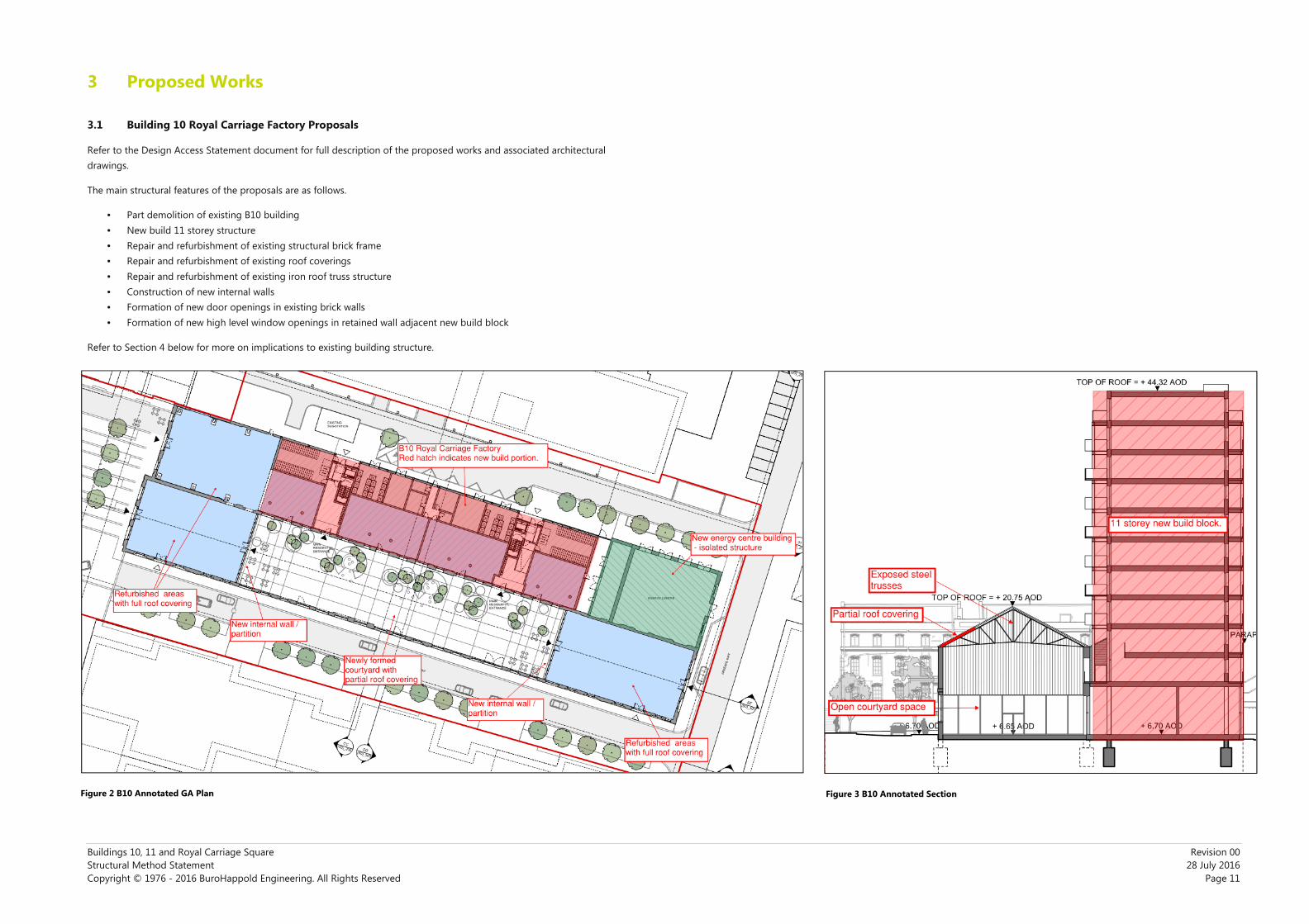
3 Proposed Works
3.1 Building 10 Royal Carriage Factory Proposals
Refer to the Design Access Statement document for full description of the proposed works and associated architectural
drawings.
The main structural features of the proposals are as follows.
• Part demolition of existing B10 building
• New build 11 storey structure
• Repair and refurbishment of existing structural brick frame
• Repair and refurbishment of existing roof coverings
• Repair and refurbishment of existing iron roof truss structure
• Construction of new internal walls
• Formation of new door openings in existing brick walls
• Formation of new high level window openings in retained wall adjacent new build block
Refer to Section 4 below for more on implications to existing building structure.
Figure 2 B10 Annotated GA Plan Figure 3 B10 Annotated Section Figure 2 B10 Annotated GA Plan Figure 3 B10 Annotated Section

Buildings 10, 11 and Royal Carriage Square Revision 00
Structural Method Statement 28 July 2016
Copyright © 1976 - 2016 BuroHappold Engineering. All Rights Reserved Page 12
3.2 Building 11 Officers' House Proposals
Refer to the Design Access Statement document for full description of the proposed works and associated architectural
drawings.
The main structural features of the proposals are as follows.
• Demolition of limited existing B11 out-buildings
• New build 6 storey structure to rear elevation
• New build bridging link structure between new and existing structures
• Refurbishment and repair to existing structure
• New roof structure to existing building
• Interface with adjacent crossrail works
Refer to Section 4 below for more on implications to existing building structure.
Figure 4 B11 Annotated GA Plan
Figure 5 B11 Annotated Section
Buildings 10, 11 and Royal Carriage Square Revision 00
Structural Method Statement 28 July 2016
Copyright © 1976 - 2016 BuroHappold Engineering. All Rights Reserved Page 13
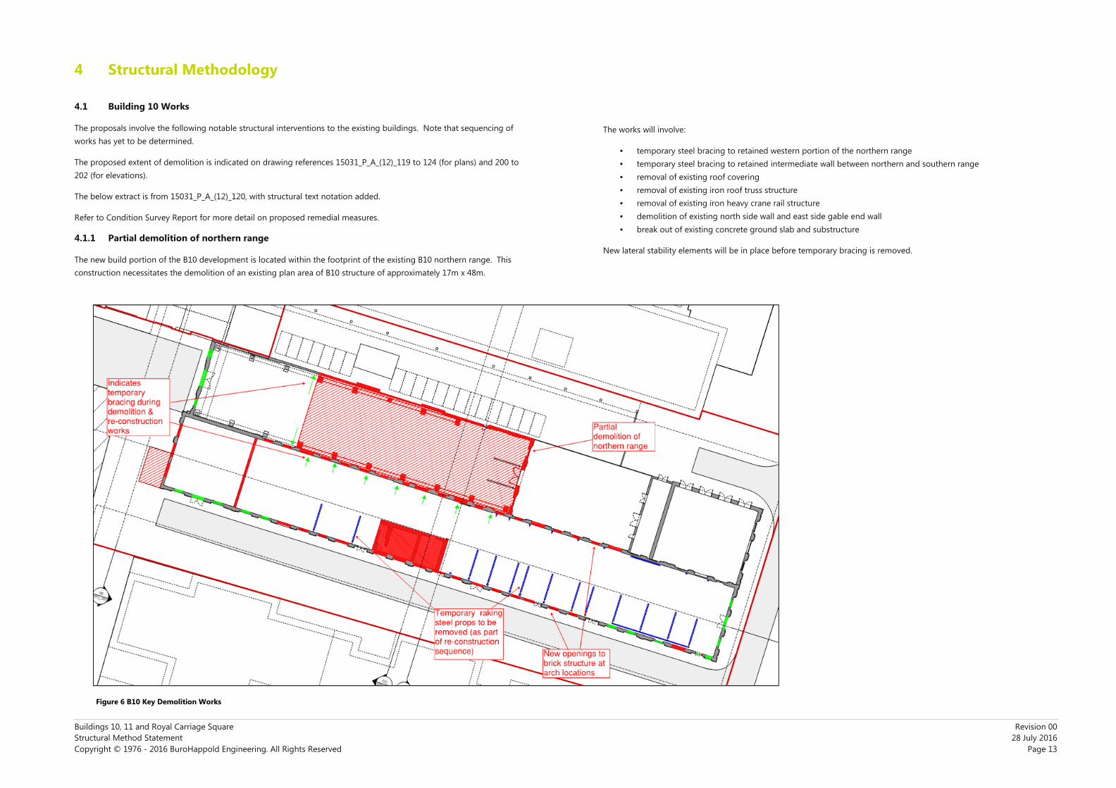
4 Structural Methodology
4.1 Building 10 Works
The proposals involve the following notable structural interventions to the existing buildings. Note that sequencing of
works has yet to be determined.
The proposed extent of demolition is indicated on drawing references 15031_P_A_(12)_119 to 124 (for plans) and 200 to
202 (for elevations).
The below extract is from 15031_P_A_(12)_120, with structural text notation added.
Refer to Condition Survey Report for more detail on proposed remedial measures.
4.1.1 Partial demolition of northern range
The new build portion of the B10 development is located within the footprint of the existing B10 northern range. This
construction necessitates the demolition of an existing plan area of B10 structure of approximately 17m x 48m.
The works will involve:
• temporary steel bracing to retained western portion of the northern range
• temporary steel bracing to retained intermediate wall between northern and southern range
• removal of existing roof covering
• removal of existing iron roof truss structure
• removal of existing iron heavy crane rail structure
• demolition of existing north side wall and east side gable end wall
• break out of existing concrete ground slab and substructure
New lateral stability elements will be in place before temporary bracing is removed.
Figure 6 B10 Key Demolition Works Figure 6 B10 Key Demolition Works

Buildings 10, 11 and Royal Carriage Square Revision 00
Structural Method Statement 28 July 2016
Copyright © 1976 - 2016 BuroHappold Engineering. All Rights Reserved Page 14
4.1.2 Reinstatement of lateral stability elements to B10 external walls
The original building lateral stability was provided by internal cross-walls and external gable end walls. Between these
intermittent points of restraint, the structure relied on the diaphragm action of the roof covering and trusses to restrain
the top of the walls and transfer horizontal loading.
The 2014 engineering assessment of the structure concluded that the majority of precautionary raking propping installed
in 2006 could be removed, however, the poor condition of portions of the southern range roof meant that diaphragm
action could not be relied upon. This necessitated the retention of raking props to portions of the southern external wall.
The intent with the new proposals is to re-instate the original structural philosophy. The involves the following:-
• introduction of internal crosswalls to the southern range between the end commercial spaces and courtyard
(these could be in the form of brick to match existing or could be distinct steel bracing elements integrated into
a glazed façade partition)
• introduction of intermittent additional wall restraint points to the south external wall within the courtyard area
• repair or replacement as necessary of the roof covering to ensure diaphragm actions
The above will allow the removal of all temporary steel raking props.
The new restraint points to the courtyard southern external wall could be provided in a number of ways. Options include:
• brick buttresses that act as vertical cantilevers
• steel restraint posts that act as vertical cantilevers
• re-use of the existing heavy iron crane rail structure due to be removed from the demolished north range
All of the above options involve the construction of new substructure against the existing walls. This substructure would
be coordinated with existing footings and could be in the form of pile caps and mini-pile groups.
The stability of the structure in the final condition will be as indicated below:
Figure 7 B10 Proposed lateral stability system Figure 7 B10 Proposed lateral stability system

Buildings 10, 11 and Royal Carriage Square Revision 00
Structural Method Statement 28 July 2016
Copyright © 1976 - 2016 BuroHappold Engineering. All Rights Reserved Page 15
4.1.3 Partial removal of roof covering to southern range
As per the architectural intent, the majority of the roof covering to the new courtyard area of B10 is to be removed. The
reduced roof extent means a less effective diaphragm action, partly driving the requirement for additional wall restraint to
the courtyard area.
Related structural works would include:
• repair/replacement of retained roof covering area, in order to ensure diaphragm action is maintained in reduced
roof
• refurbishment/repair of existing iron roof trusses (see 4.1.4)
• possible addition of new bracing elements to the truss structure (likely new mild steel sections)
• addition of high performance corrosion protection to exposed iron roof structure
• consideration of protection to former internal brick wall areas now to be exposed to weather
• consideration of steel truss connection detailing and wall connections with regards to weather and corrosion
protection
4.1.4 Refurbishment and repair to existing roof truss structure
Refer to Condition Survey Report for existing condition of structure and proposed repair/refurbishment methodologies.
Related structural works will include:
• replacement of damaged, bent, badly corroded or missing structural elements
• possible addition of new bracing elements to the truss structure (likely new mild steel sections)
• repair/refurbishment of truss support points in support walls
• application of appropriate corrosion protection system
Figure 8 B10 Roof level works Figure 8 B10 Roof level works

Buildings 10, 11 and Royal Carriage Square Revision 00
Structural Method Statement 28 July 2016
Copyright © 1976 - 2016 BuroHappold Engineering. All Rights Reserved Page 16
4.1.5 Repair to existing brick structure
All retained brick structure will be inspected and repaired as necessary in a sympathetic manner to match existing
construction. Refer to Condition Survey Report for proposed remedial works to brick structure.
4.1.6 New openings to existing brick structure
A number of new door openings are proposed for existing external walls. The existing walls are made up of arched
thicker brick portions with thinner infill within the arch. Current intent is for all new door openings to be located within
the thinner infill areas within the arches.
A number of new high level window openings are proposed to the existing wall that abuts the new build block. The
resultant slim portion of retained structure above the new window openings will support roof truss bearing points. The
retained brick by itself will likely be insufficient to support the truss loads.
A potential solution is the addition of steel framing to the window frames (as noted in drawing below). Alternatively, it
may be found that replacement of this upper existing brick with new structure is necessary. In this scenario, the existing
roof trusses would need propping whilst the new structure was installed.
See Fig 9 below, taken from drawing from 15031_P_A_(00)_301.
Figure 9 B10 Southern range – proposed north wall works Figure 9 B10 Southern range – proposed north wall works
Buildings 10, 11 and Royal Carriage Square Revision 00
Structural Method Statement 28 July 2016
Copyright © 1976 - 2016 BuroHappold Engineering. All Rights Reserved Page 17
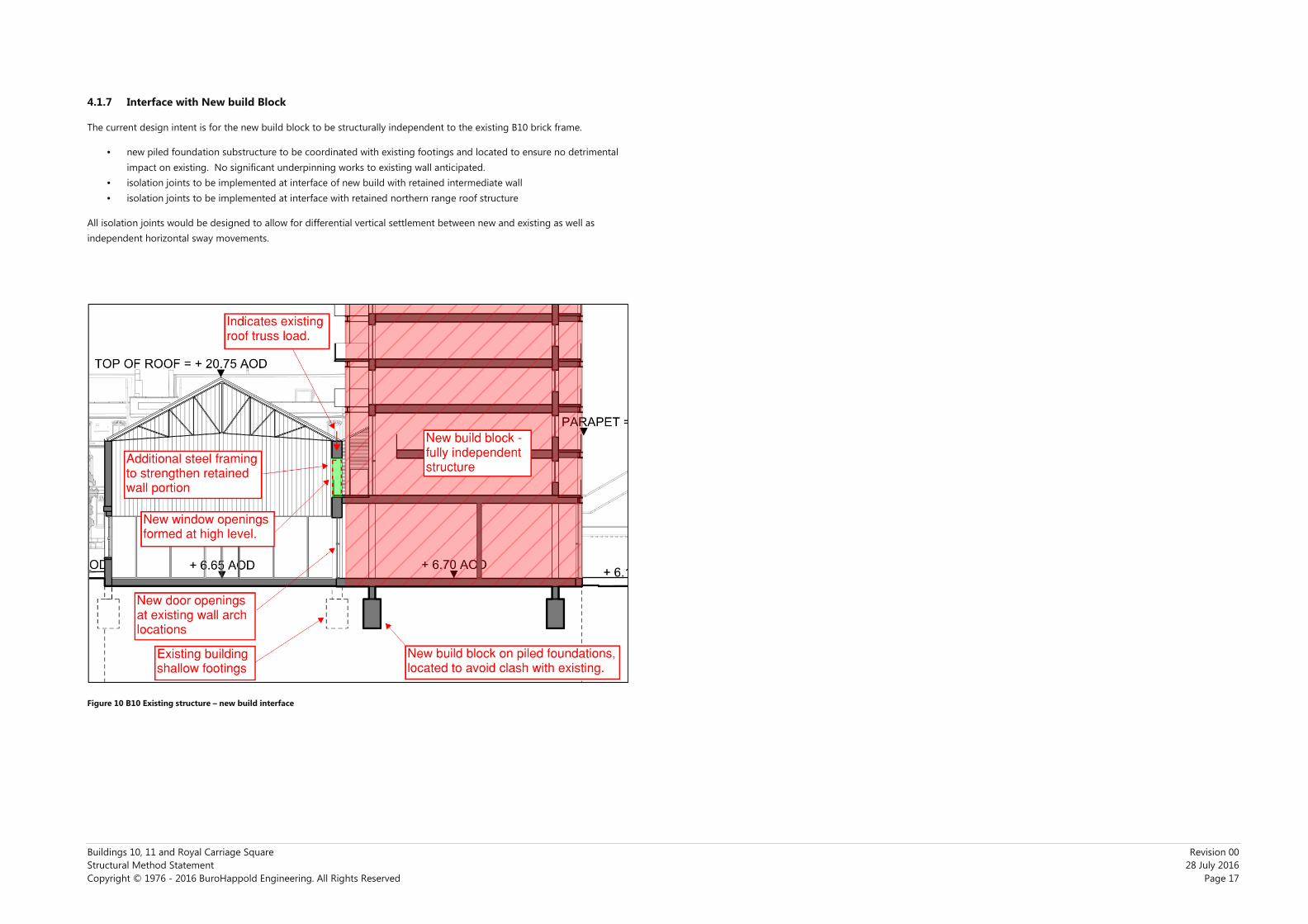
4.1.7 Interface with New build Block
The current design intent is for the new build block to be structurally independent to the existing B10 brick frame.
• new piled foundation substructure to be coordinated with existing footings and located to ensure no detrimental
impact on existing. No significant underpinning works to existing wall anticipated.
• isolation joints to be implemented at interface of new build with retained intermediate wall
• isolation joints to be implemented at interface with retained northern range roof structure
All isolation joints would be designed to allow for differential vertical settlement between new and existing as well as
independent horizontal sway movements.
Figure 10 B10 Existing structure – new build interface

Buildings 10, 11 and Royal Carriage Square Revision 00
Structural Method Statement 28 July 2016
Copyright © 1976 - 2016 BuroHappold Engineering. All Rights Reserved Page 18
4.2 Building 11 Works
The proposals involve the following notable structural interventions to the existing buildings. Note that sequencing of
works has yet to be determined.
4.2.1 Minor demolition works
The proposed extent of demolition is indicated on drawing references 15031_P_A_(12)_119 to 124 (for plans) and 200 to
202 (for elevations).
Refer to Fig 11 below, an extract from 15031_P_A_(12)_120. This is fairly typical of what is proposed for the building.
Figure 11 B11 Key demolition works
Demolition / break out works broadly consist of:-
• Demolition of existing rear-side extension pieces and under-croft areas
• Removal of selected internal wall partitions
• New wall openings
The areas highlighted for demolition are not considered critical for building stability as there is more than sufficient
retained cross wall structure. However, internal partitions to be removed may be load bearing structures in terms of
supporting localised areas of floor plate. Therefore a new support system for floor joists in these areas may be required.
New door openings are frequently formed at existing window locations and therefore overall integrity of the wall should
not be effected. For entirely new openings, new lintel will be required above.
4.2.2 Internal structural works
Refer to Condition Survey Report document for existing structural condition.
In accordance with the content of the report, the overall structural integrity of the building is intact. The building is in
principle laterally stable. The over-arching intent is to retain as much existing structure as possible.
• existing brick stability walls, internal and external to be retained
• majority of existing floor primary timber beams, joists and planks to be retained
• some new doorways required to be punched through existing walls
• new staircase structures to be added
• repairs to existing brick walls
• repairs / replacement of existing lintels
The new floor build up will need careful consideration. As a minimum, the build up will need to take into account
• fire separation between floors
• fire protection of floor structure
• acoustic treatment between floors
• vibration
• load bearing capacity of existing structure
The build up above and ceiling below the existing structure will be determined as part of design development in the next
stage. The current intent is to provide a floor plate build-up that provides a continuous diaphragm action and securely
ties in all perimeter walls.
We note that the conclusions of the Condition Survey Report are that the existing structure is largely in good condition.
However, there are areas that have deteriorated significantly and will need replacement. The intent is that any
replacement structure replicates the structural materials and methodology of existing. Refer to Condition Survey Report
for more.
Figure 12 B11 Proposed floor construction

Buildings 10, 11 and Royal Carriage Square Revision 00
Structural Method Statement 28 July 2016
Copyright © 1976 - 2016 BuroHappold Engineering. All Rights Reserved Page 19
4.2.3 New roof structure
The existing roof structure is to be removed as part of the demolition works. New roof structure will likely be framed out
in steel and will bear onto the existing external brick walls and internal central load bearing spine wall.
See Fig 13 below.
Figure 13 B11 New roof support system
4.2.4 New build elements
The 6 storey new build block is an independent structure that is located approximately 7m from the rear face of the
existing building structure. The new build block will likely be supported off piled foundations, possibly extending ~20m
down to thanet sands. We do not anticipate this new build portion detrimentally effecting the existing B11 structure.
4.2.5 New build link structure
The link structure is primarily formed of steel walkways that bridge the gap between existing B11 structure and the new
build block. The walkways will be supported off the existing rear load bearing brick wall. The support points will largely
coincide with the new doorway openings that will be required on this elevation. Localised strengthened bearing points
are expected to be required, however the global capacity of the refurbished wall is expected to be sufficient without
significant strengthening.
The level of the new build link area lower ground floor is anticipated to be below existing lower ground floor by
approximately a metre. It is anticipated that existing footings will clash with the new step in level and underpinning will
be required along the rear facade line.

Buildings 10, 11 and Royal Carriage Square Revision 00
Structural Method Statement 28 July 2016
Copyright © 1976 - 2016 BuroHappold Engineering. All Rights Reserved Page 20
4.2.6 Crossrail interface
The Crossrail basement box lies approximately 6m from the southern gable end to the existing building structure.
The construction of the deep basement structure is complete and therefore we expect the majority of related movements
in the existing B11 building to have occurred.
There is a further detailed interface at this location, where the Crossrail access walkway abuts the new and existing
portions of B11. See preliminary mark-up below. It should be noted that the access walkway consists of slab on grade
adjacent the existing B11 structure, therefore we do not anticipate any impact on existing above or below ground
structure.
The intent is for the new build B11 portions to be structurally isolated from the adjacent Crossrail structure. An
appropriate structural scheme will be developed in the next phase.
Figure 14 B11 Crossrail interface Figure 14 B11 Crossrail interface

Buildings 10, 11 and Royal Carriage Square Revision 00
Structural Method Statement 28 July 2016
Copyright © 1976 - 2016 BuroHappold Engineering. All Rights Reserved
Appendix A
N/A

Oliver Blythe Buro Happold Limited 17 Newman Street London W1T 1PD UK
T: +44 (0)207 927 9700 F: +44 (0)870 787 4145 Email: [email protected]