rpk-1.5 model rpk units fsn1m fsnm nominal cooling ... · rpk-1.5 fsnm rpk2.0 fsnm rpk-2.5 fsnm...
TRANSCRIPT

2/8 GENERAL DATA
2.1.5. RPK - WALL TYPE
RPK FSN(1)M
MODEL RPK UnitsRPK-1.5FSN1M
RPK-1.5FSNM
RPK2.0FSNM
RPK-2.5FSNM
RPK3.0FSNM
RPK4.0FSNM
Nominal Cooling Capacity kW 3.60 3.60 5.00 6.30 7.10 10.00Nominal Heating Capacity kW 4.00 4.00 5.60 7.00 8.00 11.20Air Flow Rate (Hi/Me/Lo) m³/min 11/10/9 13/11/9 14/12/10 22/18/15 22/18/15 26/24/20Fan Motor W 20 20 20 40 40 41Sound Pressure Level(Overall A Scale) (Hi/Me/Lo) dB (A) 40-38-36 39/37/34 40/38/36 43/40/37 43/40/37 49/46/43
Height mm 280 295 295 360 360 360Width mm 780 1.030 1.030 1.390 1.390 1390
OuterDimensions
Depth mm 210 183 183 225 225 225Net Weight kg 10 12 12 21 21 22Color - Pearl WhiteRefrigerant - R410A (Nitrogen Charged in Factory for Corrosion-Resistance)Connections - Flare Nuts Connection (with Flare Nuts)
Liquid Line mm(in) Ø 6.35 (1/4) Ø6.35 (1/4) Ø6.35 (1/4) Ø9.53 (3/8) Ø9.53 (3/8) Ø9.53 (3/8)RefrigerantPiping Gas Line mm(in) Ø 12.7 (1/2) Ø12.7 (1/2) Ø15.88 (5/8) Ø15.88 (5/8) Ø15.88 (5/8) Ø15.88 (5/8)
Condensate Drain Ø 26 OD Ø 26 OD Ø26 OD Ø26 OD Ø26 OD Ø26 ODPacking Measurement m³ 0.07 0.07 0.11 0.20 0.20 0.20Standard Accessories - Mounting BracketsRemote Control Switch - PC-P1HE or PC-LH3A
OD: Outer Diameter
NOTE:1. The nominal cooling and heating capacity is the
combined capacity of the HITACHI standard split system,and are based on the ISO 5151.
Operation Conditions Cooling HeatingDB 27.0 °C 20.0 °C
Indoor Air Inlet TemperatureWB 19.0 °CDB 35.0 °C 7.0 °C
Outdoor Air Inlet TemperatureWB 6.0 °C
Piping Length: 7.5 meters; Piping Lift: 0 meterDB: Dry Bulb; WB: Wet Bulb
2. The Sound Pressure Level is based on the followingconditions:
-1 meter beneath the Unit.
-1 meter from discharge grille.
-Voltage of the power source for the indoor fan motor is230V.
The above data was measured in an anaechoic chamberso that reflected sound should be taken into considerationwhen installing the unit.

3/14 DIMENSIONAL DATA
3.1.13. WALL TYPE MODELS: RPK-1.5/2.0 FSNM
Units: mm
Mark Name Remarks1 Air Inlet2 Air Outlet
3 Refrigerant Gas LineØ 12.7 Flare Nut (RPK-1.5FSNM)Ø 15.88 Flare Nut (RPK-2.0FSNM)
4 Refrigerant Liquid Line Ø 6.35 Flare Nut5 Drain Pipe Ø 26 Outer Diameter6 Receiver Part7 Knockout Hole
View from A

DIMENSIONAL DATA 3/15
3.1.14. WALL TYPE MODELS: RPK-2.5~4.0 FSNM
Units: mm
Mark Name Remarks1 Air Inlet2 Air Outlet3 Refrigerant Gas Line Ø 15.88 Flare Nut4 Refrigerant Liquid Line Ø 9.35 Flare Nut5 Drain Pipe Ø 26 Outer Diameter6 Receiver Part7 Knockout Hole
3/16 DIMENSIONAL DATA
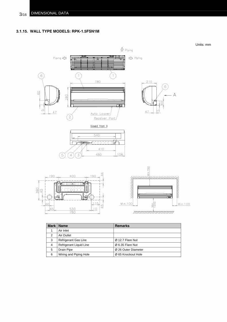
3.1.15. WALL TYPE MODELS: RPK-1.5FSN1M
Units: mm
Mark Name Remarks1 Air Inlet2 Air Outlet3 Refrigerant Gas Line Ø 12.7 Flare Nut4 Refrigerant Liquid Line Ø 6.35 Flare Nut5 Drain Pipe Ø 26 Outer Diameter6 Wiring and Piping Hole Ø 65 Knockout Hole

2/2 GENERAL DATA
2.1. GENERAL DATA FOR INDOOR UNITS
2.1.1. RCI - 4-WAY-CASSETTE TYPE
MODEL RCI Units RCI-1.5FSN1E
RCI-2.0FSN1E
RCI-2.5FSN1E
RCI-3.0FSN1E
RCI-4.0FSN1E
RCI-5.0FSN1E
RCI-6.0FSN1E
Nominal Cooling Capacity kW 3.60 5.00 6.30 7.10 10.00 12.50 14.00Nominal Heating Capacity kW 4.00 5.60 7.00 8.00 11.20 14.00 16.00Air Flow Rate (Hi/Me/Lo) m3/min 15/14/12 16/14/12 20/17/15 26/23/20 32/28/24 34/29/25 37/32/27Fan Motor W 56 56 56 56 108 108 108Sound Pressure Level(Overall A Scale)(Hi/Me/Lo)
dB (A) 32/30/28 32/30/28 32/30/28 34/32/30 38/35/33 39/37/35 42/40/36
Height mm 248 248 248 298 298 298 298Width mm 840 840 840 840 840 840 840Outer
Dimensions Depth mm 840 840 840 840 840 840 840Net Weight kg 23 24 24 26 29 29 29Refrigerant R410A (Nitrogen Charged in Factory for Corrosion-Resistance)Connections
Refrigerant Piping Flare-nut Connection (With Flare-Nuts)
Liquid Line mm(in.) ∅6.35 (1/4) ∅6.35 (1/4) ∅9.53 (3/8) ∅9.53 (3/8) ∅9.53 (3/8) ∅9.53 (3/8) ∅9.53 (3/8)
Gas Line mm(in.) ∅12.7 (1/2) ∅15.88 (5/8) ∅15.88 (5/8) ∅15.88 (5/8) ∅15.88 (5/8) ∅15.88 (5/8) ∅15.88 (5/8)
Condensate Drain mm ∅32 OD ∅32 OD ∅32 OD ∅32 OD ∅32 OD ∅32 OD ∅32 ODPacking Measurements m3 0.22 0.22 0.22 0.26 0.26 0.26 0.26Adaptable Air Panel Model - P-G23WA2Color (Munsell Code) - Spring. White (4.1Y8.5 / 0.7)
Height mm 37 37 37 37 37 37 37Width mm 950 950 950 950 950 950 950Outer
Dimensions Depth mm 950 950 950 950 950 950 950Net Weight kg 6 6 6 6 6 6 6Packing Measurements m3 0.08 0.08 0.08 0.08 0.08 0.08 0.08Remote Control Switch - PC-P1HE or PC-LH3A
OD: Outer Diameter
NOTE:1. The nominal cooling and heating capacity is the combined capacity
of the HITACHI standard split system, and are based on the ISO5151.
Operation Conditions Cooling HeatingDB 27.0 °C 20.0 °C
Indoor Air Inlet TemperatureWB 19.0 °CDB 35.0 °C 7.0 °C
Outdoor Air Inlet Temperature WB 6.0 °C
Piping Length: 7.5 meters; Piping Lift: 0 meterDB: Dry Bulb; WB: Wet Bulb
2. The Sound Pressure Level is based on the followingconditions:
– 1.5 meters beneath the Unit
– Voltage of the power source for the indoor fan motor is230V.
The above data was measured in an anaechoic chamberso that reflected sound should be taken into considerationwhen installing the unit.
3. Panel P-G23WA2 is equipped with an automaticswing louver system.

3/2 DIMENSIONAL DATA
3.1. INDOOR UNITS
3.1.1. 4-WAY CASSETTE TYPE MODELS: RCI-1.5~6.0 WITH AIR PANEL P-G23WA2
Units: mm
Mark Name Remarks
1 Air Inlet2 Air Outlet 4-way3 Refrigerant Gas Line Øa Flare Nut4 Refrigerant Liquid Line Øb Flare Nut5 Drain Pipe Ø32 Outer Diameter6 Wiring Hole for conduit tube Ø32.5 knockout hole7 Wiring Hole 30x39 Hole8 Suspension bracket9 Suspension Bolt 4-M10 or W3/8
Mark Name Remarks
10 Supply Duct Connection 150x385 knockout hole11 Supply Duct Connection 150x400 knockout hole12 Air grille13 Panel14 Service Access Panel15 Piping Connection16 Ceiling Opening Hole
View from A
Service Space(Multiple Installation)
Surroundingsin the ceiling
Model /Pipe Size a b
RCI-1.5 12.7 6.35RCI-2.0 15.88 6.35RCI-2.5 15.88 9.53RCI-3.0 15.88 9.53RCI-4.0 15.88 9.53RCI-5.0 15.88 9.53RCI-6.0 15.88 9.53
(mm)Unit HP BRCI-1.5~2.5 248RCI-3.0~6.0 298
Service Space(Single Installation)
GENERAL DATA 2/3
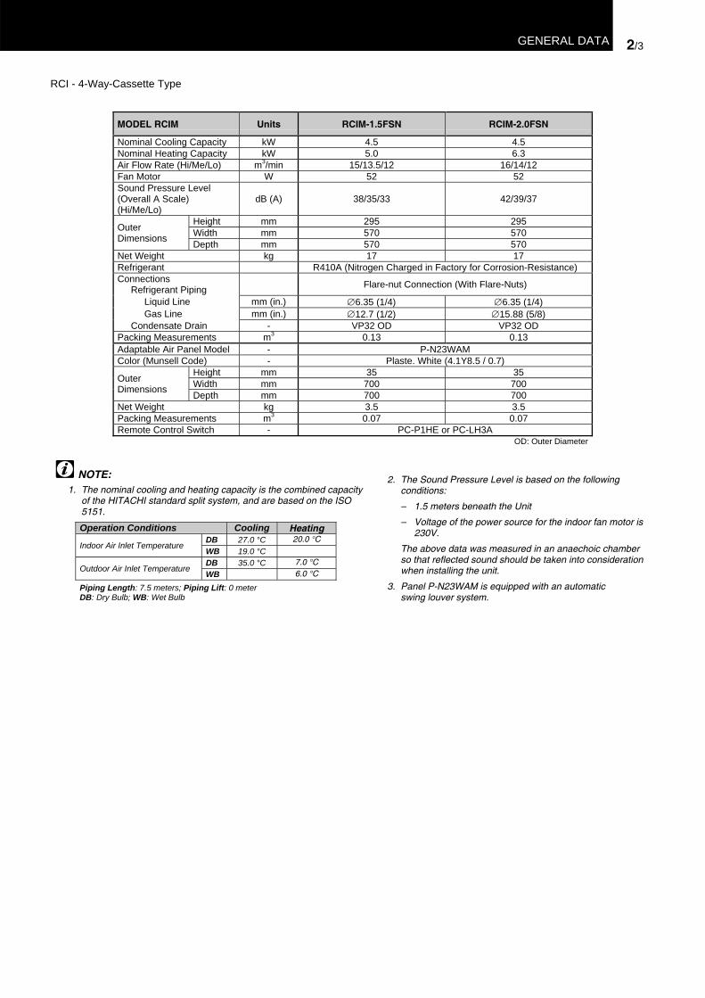
RCI - 4-Way-Cassette Type
MODEL RCIM Units RCIM-1.5FSN RCIM-2.0FSN
Nominal Cooling Capacity kW 4.5 4.5Nominal Heating Capacity kW 5.0 6.3Air Flow Rate (Hi/Me/Lo) m3/min 15/13.5/12 16/14/12Fan Motor W 52 52Sound Pressure Level(Overall A Scale)(Hi/Me/Lo)
dB (A) 38/35/33 42/39/37
Height mm 295 295Width mm 570 570Outer
Dimensions Depth mm 570 570Net Weight kg 17 17Refrigerant R410A (Nitrogen Charged in Factory for Corrosion-Resistance)Connections
Refrigerant Piping Flare-nut Connection (With Flare-Nuts)
Liquid Line mm (in.) ∅6.35 (1/4) ∅6.35 (1/4)Gas Line mm (in.) ∅12.7 (1/2) ∅15.88 (5/8)
Condensate Drain - VP32 OD VP32 ODPacking Measurements m3 0.13 0.13Adaptable Air Panel Model - P-N23WAMColor (Munsell Code) - Plaste. White (4.1Y8.5 / 0.7)
Height mm 35 35Width mm 700 700Outer
Dimensions Depth mm 700 700Net Weight kg 3.5 3.5Packing Measurements m3 0.07 0.07Remote Control Switch - PC-P1HE or PC-LH3A
OD: Outer Diameter
NOTE:1. The nominal cooling and heating capacity is the combined capacity
of the HITACHI standard split system, and are based on the ISO5151.
Operation Conditions Cooling HeatingDB 27.0 °C 20.0 °C
Indoor Air Inlet TemperatureWB 19.0 °CDB 35.0 °C 7.0 °C
Outdoor Air Inlet Temperature WB 6.0 °C
Piping Length: 7.5 meters; Piping Lift: 0 meterDB: Dry Bulb; WB: Wet Bulb
2. The Sound Pressure Level is based on the followingconditions:
– 1.5 meters beneath the Unit
– Voltage of the power source for the indoor fan motor is230V.
The above data was measured in an anaechoic chamberso that reflected sound should be taken into considerationwhen installing the unit.
3. Panel P-N23WAM is equipped with an automaticswing louver system.

DIMENSIONAL DATA 3/3
3.1.2. 4-WAY CASSETTE TYPE MODELS: RCIM-1.5/2.0 WITH AIR PANEL P-N23WAM
Units: mm
Mark Name Remarks
1 Air Inlet2 Air Outlet 4-way3 Refrigerant Gas Line Øa Flare Nut4 Refrigerant Liquid Line Øb Flare Nut5 Drain Pipe Ø32 Outder Diameter6 Wiring Hole7 Suspension bracket8 Suspension Bolt 4-M10 or W3/8
(mm)Model a b
RCIM-1.5 Ø12.7 Ø6.35RCIM-2.0 Ø15.88 Ø6.35

2/4 GENERAL DATA
2.1.2. RCD - 2-WAY-CASSETTE TYPE
MODEL RCD Units RCD-1.5FSN RCD-2.0FSN RCD-2.5FSN RCD-3.0FSN RCD-4.0FSN RCD-5.0FSN
Nominal Cooling Capacity kW 3.60 5.00 6.30 7.10 10.00 12.50
Nominal Heating Capacity kW 4.00 5.60 7.00 8.00 11.20 14.00Air Flow Rate (Hi/Me/Lo) m3/min 12/10/8.5 15/13/11 19/16/14 22/19/16 28/24/21 34/29/25Fan Motor W 35 35 55 55 35x2 35x2Sound Pressure Level(Overall A Scale) (Hi/Me/Lo) dB (A) 35/32/30 35/32/30 38/34/31 40/36/33 40/36/33 43/40/36
Height mm 298 298 298 298 298 298Width mm 860 860 860 860 1420 1420Outer DimensionsDepth mm 620 620 620 620 620 620
Net Weight kg 27 27 30 30 48 48Refrigerant R410A (Nitrogen Charged in Factory for Corrosion-Resistance)Connections
Refrigerant Piping Flare-nut Connection (With Flare-Nuts)
Liquid Line mm (in.) ∅6.35 (1/4) ∅6.35 (1/4) ∅9.53 (3/8) ∅9.53 (3/8) ∅9.53 (3/8) ∅9.53 (3/8)Gas Line mm (in.) ∅12.7 (1/2) ∅15.88 (5/8) ∅15.88 (5/8) ∅15.88 (5/8) ∅15.88 (5/8) ∅15.88 (5/8)
Condensate Drain mm Ø32 OD Ø32 OD Ø32 OD Ø32 OD Ø32 OD Ø32 ODPacking Measurements m3 0.23 0.23 0.23 0.23 0.37 0.37Standard accessories - -Adaptable Air Panel Model P-G23DWA1 P-G46DWA1Color Silky White
Height mm 30+10 30+10 30+10 30+10 30+10 30+10Width mm 1100 1100 1100 1100 1660 1660Outer DimensionsDepth mm 710 710 710 710 710 710
Net Weight kg 6 6 6 6 8 8Packing Measurements m3 0.10 0.10 0.10 0.10 0.15 0.15Remote Control Switch - PC-P1HE
OD: Outer Diameter
NOTE:1. The nominal cooling and heating capacity is the combined
capacity of the HITACHI standard split system, and arebased on the ISO 5151
Operation Conditions Cooling HeatingDB 27.0 °C 20.0 °C
Indoor Air Inlet TemperatureWB 19.0 °CDB 35.0 °C 7.0 °C
Outdoor Air Inlet Temperature WB 6.0 °C
Piping Length: 7.5 meters; Piping Lift: 0 meterDB: Dry Bulb; WB: Wet Bulb
2. The Sound Pressure Level is based on the followingconditions:
– 1.5 meters beneath the Unit
– Voltage of the power source for the indoor fan motoris 230V.
The above data was measured in an anaechoicchamber so that reflected sound should be taken intoconsideration when installing the unit.
3. Panels P-G23DWA1 and P-G46WA1 are equipped withan automatic swing louver system.

3/4 DIMENSIONAL DATA
3.1.3. 2-WAY CASSETTE TYPE MODELS: RCD-1.5~3.0 WITH AIR PANEL P-G23DWA1
Units: mm
(mm)Model / Pipe Sizes Øa Øb
RCD-1.5 12.7 6.35RCD-2.0 15.88 6.35RCD-2.5 15.88 9.53RCD-3.0 15.88 9.53
Mark Name Remarks
1 Air Inlet2 Air Outlet 2-way3 Refrigerant Gas Line Øa Flare Nut4 Refrigerant Liquid Line Øb Flare Nut5 Drain Pipe Ø32 Outer Diameter6 Hole for Suspension Bolt 890 x 540
Mark Name Remarks
7 Ceiling Open Hole 1060 x 6708 Suspension Bracket9 Wiring Hole 36 x 39mm
10 Supply Duct Connection 2 – 150 x 40011 Service Access Panel12 Piping Connection13 Wiring Connection Cable 32.5mm14 Self-Tapping Screw 9-M4 / 10 M4
Surroundings inthe Ceiling
View from A
SingleInstallation
DoubleInstallation
View from B
Enlarged view of D View from E
Service Space

DIMENSIONAL DATA 3/5
3.1.4. 2-WAY CASSETTE TYPE MODELS: RCD-4.0/5.0 WITH AIR PANEL P-G46DWA1
Units: mm
Mark Name Remarks
1 Air Inlet2 Air Outlet 2-way3 Refrigerant Gas Line Ø15.88 Flare Nut4 Refrigerant Liquid Line Ø9.53 Flare Nut5 Drain Pipe Ø32 Outer Diameter6 Hole for Suspension Bolt 1450 x 540
Mark Name Remarks
7 Ceiling Open Hole 1620 x 6708 Suspension Bracket9 Wiring Hole 36 x 39mm
10 Supply Duct Connection 2 – 150 x 40011 Service Access Panel12 Piping Connection13 Wiring Connection Cable 32.5mm14 Self-Tapping Screw 9-M4/10 M4
View from B
View from E
SingleInstallation
DoubleInstallation
View from A
Surroundings inthe Ceiling
Enlarged view of DService Space

GENERAL DATA 2/5
2.1.3. RPC - CEILING TYPE
MODEL RPC Units RPC-2.0FSNE
RPC-2.5FSNE
RPC-3.0FSNE
RPC-4.0FSNE
RPC-5.0FSNE
RPC-6.0FSNE
Nominal Cooling Capacity kW 5.00 6.30 7.10 10.00 12.50 14.00Nominal Heating Capacity kW 5.60 7.00 8.00 11.20 14.00 16.00Air Flow Rate (Hi/Me/Lo) m3/min 15/13/10 18/16/12 21/17/15 30/24/19 35/28/21 37/32/27Fan Motor W 75 75 75 145 145 145Sound Pressure Level(Overall A Scale) (Hi/Me/Lo) dB (A) 44/42/38 46/43/41 48/45/42 49/45/39 49/46/41 50/48/44
Height mm 163 163 163 225 225 225Width mm 1094 1314 1 314 1314 1574 1574Outer
Dimensions Depth mm 625 625 625 625 625 625Net Weight kg 28 31 31 35 41 41Color Spring White (4.1Y 8.5 / 0.7)Refrigerant R410A (Nitrogen Charged in Factory for Corrosion-Resistance)Connections
Refrigerant Piping Flare-nut Connection (With Flare-Nuts)
Liquid Line mm (in.) Ø6.35 (1/4) Ø9.53 (3/8) Ø9.53 (3/8) Ø9.53 (3/8) Ø9.53 (3/8) Ø9.53 (3/8)
Gas Line mm (in.) Ø15.88(5/8)
Ø15.88(5/8)
Ø15.88(5/8)
Ø15.88(5/8)
Ø15.88(5/8)
Ø15.88(5/8)
Condensate Drain mm ∅25 OD ∅25 OD ∅25 OD ∅25 OD ∅25 OD ∅25 ODPacking Measurements m3 0.24 0.29 0.29 0.36 0.43 0.43Remote Control Switch - PC-P1HE
ºOD: Outer Diameter
NOTE:1. The nominal cooling and heating capacity is the combined
capacity of the HITACHI standard split system, and are based onthe ISO 5151..
Operation Conditions Cooling HeatingDB 27.0 °C 20.0 °C
Indoor Air Inlet TemperatureWB 19.0 °CDB 35.0 °C 7.0 °C
Outdoor Air Inlet TemperatureWB 6.0 °C
Piping Length: 7.5 meters; Piping Lift: 0 meterDB: Dry Bulb; WB: Wet Bulb
2. The Sound Pressure Level is based on the followingconditions:
-1 meter beneath the Unit
-1 meter from Discharge grille
-Voltage of the power source for the indoor fan motor is230V.
The above data was measured in an anaechoic chamberso that reflected sound should be taken into considerationwhen installing the unit.

3/6 DIMENSIONAL DATA
3.1.5. CEILING TYPE MODELS: RPC-2.0
Units: mm
Mark Name Remarks
1 Air Discharge2 Air Inlet
3 Hole for Refrigerant PipingKnockout Hole for TopSide. Refrigerant PipingArrangement
4 Condensate Drain PipingConnection
(for A Side)Ø25 Outer Diameter.
5 Hole for Refrigerant Piping Knockout Hole6 Hole for Conduit Tube ∅32.5 Knockout Hole
Mark Name Remarks
7 Condensate Drain PipingConnection
(for B Side) Ø25 O.D.Knockout Hole
8 Refrigerant Liquid Line ∅6.35 Flare Nut9 Refrigerant Gas Line ∅15.88 Flare Nut
10 Hole for Suspension Bolt ∅12 Removable
11 Hole for Suspension Bolt ∅12 bracket can beattached to this position
Piping Connection Arrangement
Service Space

DIMENSIONAL DATA 3/7
3.1.6. CEILING TYPE MODELS: RPC-2.5/3.0
Units: mm
Mark Name Remarks
1 Air Discharge2 Air Inlet
3 Hole for Refrigerant PipingKnockout Hole for TopSide. Refrigerant PipingArrangement
4 Condensate Drain PipingConnection
(for A Side)Ø25 Outer Diameter
5 Hole for Refrigerant Piping Knockout Hole
Mark Name Remarks
6 Hole for Conduit Tube ∅32.5 Knockout Hole
7 Condensate Drain PipingConnection
(for B Side) Ø25 O.D.Knockout Hole
8 Refrigerant Liquid Line ∅9.53 Flare Nut9 Refrigerant Gas Line ∅15.88 Flare Nut
10 Hole for Suspension Bolt ∅12 Removable
11 Hole for Suspension Bolt ∅12 bracket can beattached to this position
Service Space
Fixing Bracket
Piping Connection Arrangement

3/8 DIMENSIONAL DATA
3.1.7. CEILING TYPE MODELS: RPC-4.0
Units: mm
Mark Name Remarks
1 Air Discharge2 Air Inlet
3 Hole for Refrigerant PipingKnockout Hole for TopSide. Refrigerant PipingArrangement
4 Condensate Drain PipingConnection
(for A Side)Ø25 Outer Diameter
5 Hole for Refrigerant Piping Knockout Hole
Mark Name Remarks
6 Hole for Conduit Tube ∅32.5 Knockout Hole
7 Condensate Drain PipingConnection
(for B Side) Ø25 O.D.Knockout Hole
8 Refrigerant Liquid Line ∅9.53 Flare Nut9 Refrigerant Gas Line ∅15.88 Flare Nut
10 Hole for Suspension Bolt ∅12 Removable
11 Hole for Suspension Bolt ∅12 bracket can beattached to this position
Piping Connection Arrangement
Service Space
Fixing Bracket

DIMENSIONAL DATA 3/9
3.1.8. CEILING TYPE MODELS: RPC-5.0/6.0
Units: mm
Mark Name Remarks
1 Air Discharge2 Air Inlet
3 Hole for Refrigerant PipingKnockout Hole for TopSide. Refrigerant PipingArrangement
4 Condensate Drain PipingConnection
(for A Side)Ø25 Outer Diameter
5 Hole for Refrigerant Piping Knockout Hole
Mark Name Remarks
6 Hole for Conduit Tube ∅32.5 Knockout Hole
7 Condensate Drain PipingConnection
(for B Side) Ø25 O.D.Knockout Hole
8 Refrigerant Liquid Line ∅9.53 Flare Nut9 Refrigerant Gas Line ∅15.88 Flare Nut
10 Hole for Suspension Bolt ∅12 Removable
11 Hole for Suspension Bolt ∅12 bracket can beattached to this position
Piping Connection Arrangement
Service Space
Fixing Bracket

2/6 GENERAL DATA
2.1.4. RPI - IN THE_CEILING TYPE
MODEL RPI Units RPI-1.5FSNE
RPI-2.0FSNE
RPI-2.5FSNE
RPI-3.0FSNE
RPI-4.0FSNE
RPI-5.0FSNE
RPI-6.0FSNE
Nominal Cooling Capacity kW 3.60 5.00 6.30 7.10 10.00 12.50 14.00Nominal HeatingCapacity kW 4.00 5.60 7.00 8.00 11.20 14.00 16.00
HSP – 16/15/11 19/17/14 22/20/16 30/28/25 35/31/28 36/34/29STDSP 10/9/7 16/14/12 19/17/15 22/20/17 30/29/26 35/32/29 36/33/31Air Flow Rate
(Hi/Me/Lo)LSP
-m3/min
- – 16/16/13 19/19/15 22/22/18 30/30/28 35/35/31 36/36/33HSP – 12/10/6 12/10/6 12/10/6 12/10/8 12/10/8 12/10/8STDSP 5/5/5 8/6/5 8/6/5 8/6/5 8/7/6 8/7/6 8/7/6Static Pressure
(Hi/Me/Lo)LSP
-mm
- – 3/3/2 3/3/2 3/3/2 3/3/2 3/3/2 3/3/2Fan Motor W 55 80 225 225 350 350 350
HSP – 40/38/35 41/39/36 42/40/37 44/42/38 47/46/44 48/47/45STDSP 38/37/35 39/37/34 40/38/35 40/38/35 42/41/37 45/44/43 46/45/44
Sound PressureLevel (Overall AScale) /Hi/Me/Lo) LSP
-dB (A)
- – 35/35/31 36/36/32 37/37/33 41/41/35 44/44/42 45/45/43Sound PowerLevel (Overall AScale)
HSP-
dB (A)-
57 59 60 61 63 65 66
Height mm 197 274 274 274 274 274 274Width mm 1020 1074 1074 1074 1464 1464 1464Outer
DimensionsDepth mm 574 643 643 643 643 643 643
Net Weight kg 33.5 43 45 45 51 52 52Refrigerant R410A (Nitrogen Charged in Factory for Corrosion-Resistance)Connections RefrigerantPiping Flare-Nut Connection (With Flare Nuts)
Liquid Line mm (in.) Ø6.35 (1/4) Ø6.35 (1/4) Ø9.53 (3/8) Ø9.53 (3/8) Ø9.53 (3/8) Ø 9.53 (3/8) Ø9.53 (3/8)Gas Line mm (in.) Ø12.7 (1/2) Ø15.88 (5/8) PC-P1HE Ø15.88 (5/8) Ø15.88 (5/8) Ø15.88 (5/8) Ø15.88 (5/8)
Condense Drain mm Ø32 OD Ø32 OD Ø32 OD Ø32 OD Ø32 OD Ø32 OD Ø32 ODPacking Measurements m³ 0.16 0.36 0.36 0.36 0.48 0.48 0.48Remote Control Switch - PC-P1HE
OD: Outer DiameterHSP: High Static Pressure ConnectionLSP: Low Static Pressure ConnectionSTDSP: Standard Static Pressure Connection
NOTE:1. The nominal cooling and heating capacity is the
combined capacity of the HITACHI standard split system,and are based on the ISO 5151.
Operation Conditions Cooling HeatingDB 27.0 °C 20.0 °C
Indoor Air Inlet TemperatureWB 19.0 °CDB 35.0 °C 7.0 °C
Outdoor Air Inlet Temperature WB 6.0 °CPiping Length: 7.5 meters; Piping Lift: 0 meterDB: Dry Bulb; WB: Wet Bulb
2. The Sound Pressure Level is based on the followingconditions:
– 1.5 meter beneath the Unit (without ceiling under theunit), applying suction duct 1m. and discharge duct 2m.
– Voltage of the power source for the indoor fan motor is230V.
The above data was measured in an anaechoic chamberso that reflected sound should be taken into considerationwhen installing the unit.

GENERAL DATA 2/7
RPI - In The_Ceiling Type
MODEL RPI Units RPI-8.0FSNE RPI-10.0FSNE
Nominal Cooling Capacity kW 20.0 25.00Nominal Heating Capacity kW 22.4 28.00Air Flow Rate (Hi/Me/Lo) m3/min 66 75Fan Motor W 1250 1250Sound Pressure Level(Overall A Scale) (Hi/Me/Lo) dB (A) (54/54/51) (55/55/52)
Height mm 475Width mm 1580Outer
Dimensions Depth mm 600Net Weight kg 85 87Refrigerant R410A (Nitrogen Charged in Factory for Corrosion-Resistance)Connections
Refrigerant Piping - Brazed Connection
Liquid Line mm (in.) 9.53 (3/8) 9.53 (3/8)Gas Line mm (in.) 19.05 (3/4) 22.2 (7/8)
Condensate Drain - Ø25 OD Ø25 ODPacking Measurements m3 0.5 0.5Standard Accessories - Air FilterRemote Control Switch - PC-P1HE
OD: Outer Diameter
NOTE:1. The nominal cooling and heating capacity is the
combined capacity of the HITACHI standard split system,and are based on the ISO 5151.
Operation Conditions Cooling HeatingDB 27.0 °C 20.0 °C
Indoor Air Inlet TemperatureWB 19.0 °CDB 35.0 °C 7.0 °C
Outdoor Air Inlet Temperature WB 6.0 °CPiping Length: 7.5 meters; Piping Lift: 0 meterDB: Dry Bulb; WB: Wet Bulb
2. The Sound Pressure Level is based on the followingconditions:
– 1.5 meter beneath the Unit (without ceiling under theunit), applying suction duct 1m. and discharge duct 2m.
– Voltage of the power source for the indoor fan motor is230V.
The above data was measured in an anaechoic chamberso that reflected sound should be taken into considerationwhen installing the unit.

CAPACITIES AND SELECTION DATA 4/19
4.7. FAN PERFORMANCE
4.7.1. RPI - FAN PERFORMANCE
RPI-1.5 RPI-2.0
Ext
erna
l Sta
tic P
ress
ure
(mm
Aq)
Ext
erna
l Sta
tic P
ress
ure
(mm
Aq)
Air Flow (m³/min) Air Flow (m³/min)RPI-2.5 RPI-3.0
Ext
erna
l Sta
tic P
ress
ure
(mm
Aq)
Ext
erna
l Sta
tic P
ress
ure
(mm
Aq)
Air Flow (m³/min) Air Flow (m³/min)RPI-4.0 RPI-5.0
Ext
erna
l Sta
tic P
ress
ure
(mm
Aq)
Ext
erna
l Sta
tic P
ress
ure
(mm
Aq)
Air Flow (m³/min) Air Flow (m³/min)
* Filter resistance
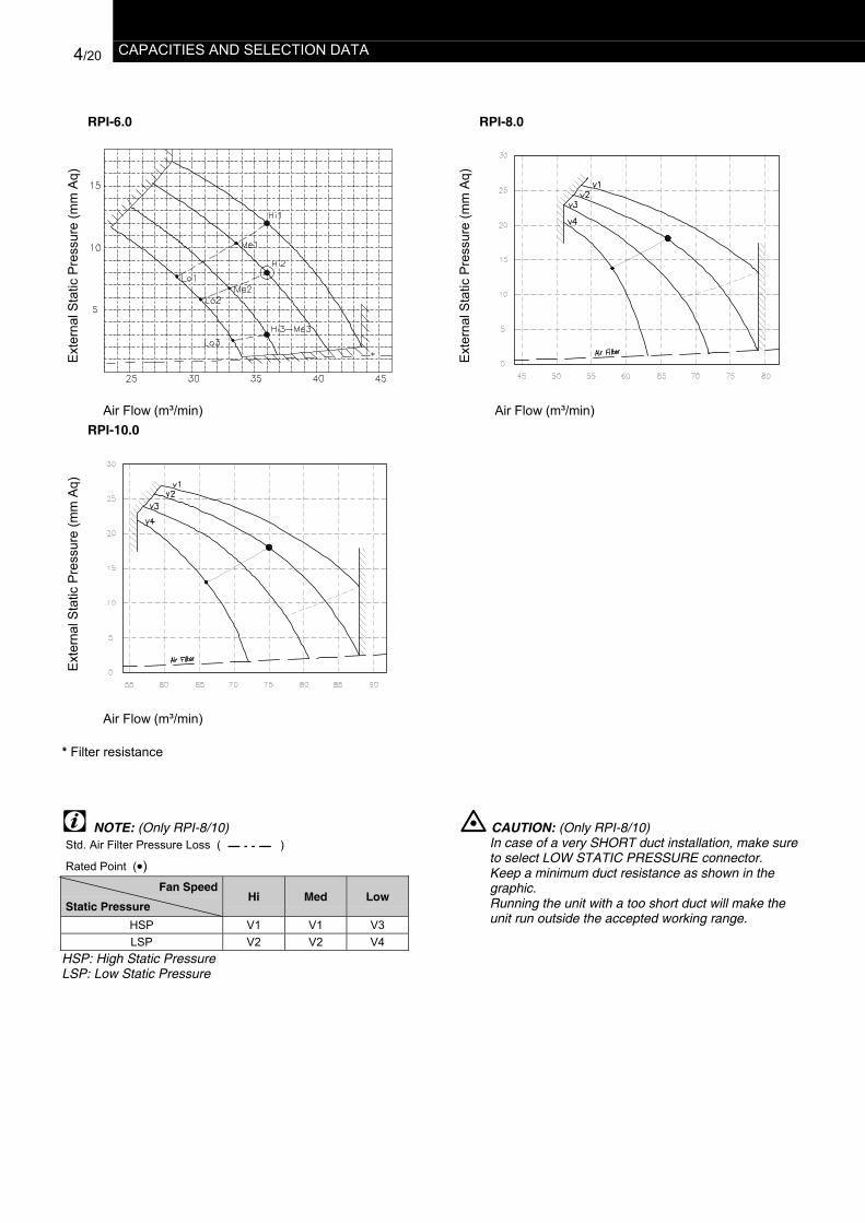
4/20 CAPACITIES AND SELECTION DATA
RPI-6.0 RPI-8.0
Ext
erna
l Sta
tic P
ress
ure
(mm
Aq)
Ext
erna
l Sta
tic P
ress
ure
(mm
Aq)
Air Flow (m³/min) Air Flow (m³/min)RPI-10.0
Ext
erna
l Sta
tic P
ress
ure
(mm
Aq)
Air Flow (m³/min)
* Filter resistance
NOTE: (Only RPI-8/10)Std. Air Filter Pressure Loss ( )
Rated Point (•)Fan Speed
Static PressureHi Med Low
HSP V1 V1 V3LSP V2 V2 V4
HSP: High Static PressureLSP: Low Static Pressure
CAUTION: (Only RPI-8/10)In case of a very SHORT duct installation, make sureto select LOW STATIC PRESSURE connector.Keep a minimum duct resistance as shown in thegraphic.Running the unit with a too short duct will make theunit run outside the accepted working range.
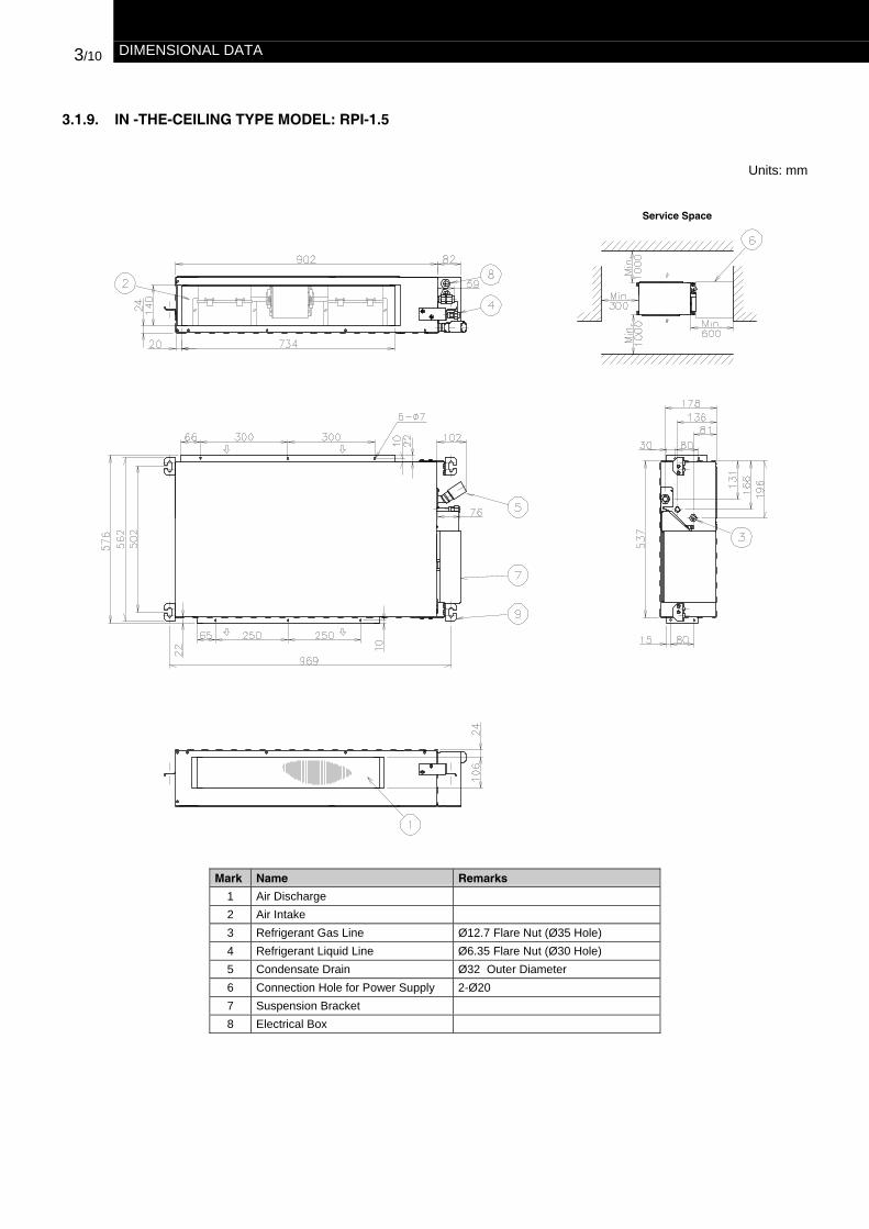
3/10 DIMENSIONAL DATA
3.1.9. IN -THE-CEILING TYPE MODEL: RPI-1.5
Units: mm
Mark Name Remarks
1 Air Discharge2 Air Intake3 Refrigerant Gas Line Ø12.7 Flare Nut (Ø35 Hole)4 Refrigerant Liquid Line Ø6.35 Flare Nut (Ø30 Hole)5 Condensate Drain Ø32 Outer Diameter6 Connection Hole for Power Supply 2-Ø207 Suspension Bracket8 Electrical Box
Service Space

DIMENSIONAL DATA 3/11
3.1.10. IN-THE-CEILING TYPE MODELS: RPI-2.0/3.0
Units: mm
Mark Name Remarks
1 Air Discharge2 Air Inlet3 Refrigerant Gas Line Øa Flare Nut (Ø 35 Hole)4 Refrigerant Liquid Line Øb Flare Nut (Ø 30 Hole)5 Condensate Drain Ø32 Outer Diameter.6 Service Space Door7 Electrical Box8 Wiring Connection9 Suspension Brackets
(mm)Model / Pipe Sizes Øa Øb
RPI-2.0 15.88 6.35RPI-2.5 15.88 9.53RPI-3.0 15.88 9.53
Service Space
3/12 DIMENSIONAL DATA
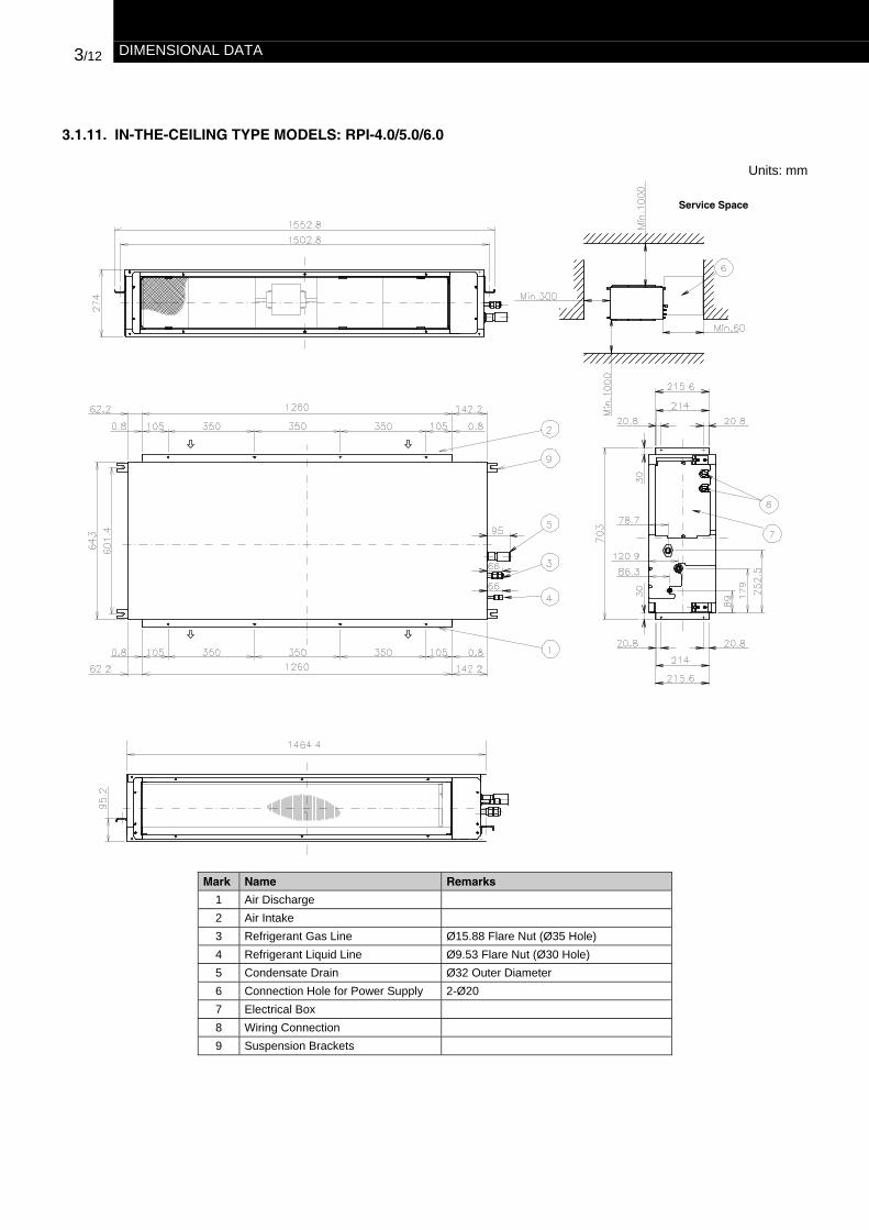
3.1.11. IN-THE-CEILING TYPE MODELS: RPI-4.0/5.0/6.0
Units: mm
Mark Name Remarks
1 Air Discharge2 Air Intake3 Refrigerant Gas Line Ø15.88 Flare Nut (Ø35 Hole)4 Refrigerant Liquid Line Ø9.53 Flare Nut (Ø30 Hole)5 Condensate Drain Ø32 Outer Diameter6 Connection Hole for Power Supply 2-Ø207 Electrical Box8 Wiring Connection9 Suspension Brackets
Service Space

3/12 DIMENSIONAL DATA
3.1.11. IN-THE-CEILING TYPE MODELS: RPI-4.0/5.0/6.0
Units: mm
Mark Name Remarks
1 Air Discharge2 Air Intake3 Refrigerant Gas Line Ø15.88 Flare Nut (Ø35 Hole)4 Refrigerant Liquid Line Ø9.53 Flare Nut (Ø30 Hole)5 Condensate Drain Ø32 Outer Diameter6 Connection Hole for Power Supply 2-Ø207 Electrical Box8 Wiring Connection9 Suspension Brackets
Service Space

DIMENSIONAL DATA 3/13
3.1.12. IN-THE-CEILING TYPE MODELS: RPI-8.0~10.0
Units: mm
Mark Name Remarks1 Air inlet2 Air Outlet3 Refrigerant Gas Line Ø28.6 Flare Nut (Ø35 Hole)4 Refrigerant Liquid Line Øa Flare Nut (Ø30 Hole)5 Condensate Drain Ø25 Outer Diameter6 Service Space Door7 Electrical Box8 Wiring Connection9 Suspension Brackets
(mm)Model aRPI-8.0 Ø12.7RPI-10.0 Ø15.88

GENERAL DATA 2/9
2.1.6. RPF & RPFI - FLOOR & FLOOR CONCEALED TYPE
MODELS RPF & RPFI Units RPF-1.5FSNE RPF-2.0FSNE RPF-2.5FSNE RPFI-1.5FSNE RPFI-2.0FSNE RPFI-2.5FSNE
Nominal Cooling Capacity kW 3.60 5.00 6.30 3.60 5.00 6.30Nominal Heating Capacity kW 4.00 5.60 7.00 4.00 5.60 7.00Air Flow Rate (Hi/Me/Lo) m3/min 12/10/9 16/14/11 16/14/11 12/10/9 16/14/11 16/14/11Fan Motor W 28 45 45 28 45 45Sound Pressure Level(Overalll A Scale)(Hi/Me/Lo)
db (A) 38/35/31 39/36/32 42/38/34 38/35/31 39/36/32 42/38/34
Height mm 630 630 630 620 620 620Width mm 1170 1420 1420 988 1238 1238Outer
dimensions Depth mm 220 220 220 220 220 220Net Weight kg 23 33 34 23 27 28Color - Spring White (4.1Y 8.5 / 0.7) ---Refrigerant - R410A (Nitrogen Charged in Factory for Corrosion-Resistance)Connections Flare Nuts Connection (with Flare Nuts)
LiquidLine
mm(in) Ø6.35 (1/4) Ø6.35 (1/4) Ø9.53 (3/8) Ø6.35 (1/4) Ø6.35 (1/4) Ø9.53 (3/8)Refrigerant
Piping GasLine
mm(in) Ø12.7 (1/2) Ø15.88 (5/8) Ø15.88 (5/8) Ø12.7 (1/2) Ø15.88 (5/8) Ø15.88 (5/8)
Condensate Drain mm Ø18.5 OD Ø18.5 OD Ø18.5 OD Ø18.5 OD Ø18.5 OD Ø18.5 ODPacking Measurements m3 0.24 0.29 0.29 0.23 0.25 0.25Remote Control Switch - PC-P1HE
OD: Outer Diameter
NOTE:1. The nominal cooling and heating capacity is the
combined capacity of the HITACHI standard split system,and are based on the ISO 5151.
Operation Conditions Cooling HeatingDB 27.0 °C 20.0 °C
Indoor Air Inlet TemperatureWB 19.0 °CDB 35.0 °C 7.0 °C
Outdoor Air Inlet TemperatureWB 6.0 °C
Piping Length: 7.5 meters; Piping Lift: 0 meterDB: Dry Bulb; WB: Wet Bulb
2. The Sound Pressure Level is based on the followingconditions:
-1 meter from the unit.
-1 meter from floor level.
-Voltage of the power source for the indoor fan motor is230V.
The above data was measured in an anaechoic chamberso that reflected sound should be taken into considerationwhen installing the unit.
3/18 DIMENSIONAL DATA
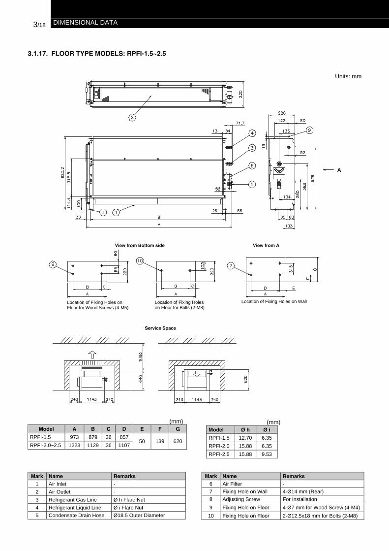
3.1.17. FLOOR TYPE MODELS: RPFI-1.5~2.5
Units: mm
(mm)Model A B C D E F G
RPFI-1.5 973 879 36 857RPFI-2.0~2.5 1223 1129 36 1107
50 139 620
(mm)Model Ø h Ø i
RPFI-1.5 12.70 6.35RPFI-2.0 15.88 6.35RPFI-2.5 15.88 9.53
Mark Name Remarks1 Air Inlet -2 Air Outlet -3 Refrigerant Gas Line Ø h Flare Nut4 Refrigerant Liquid Line Ø i Flare Nut5 Condensate Drain Hose Ø18.5 Outer Diameter
Mark Name Remarks6 Air Filter -7 Fixing Hole on Wall 4-Ø14 mm (Rear)8 Adjusting Screw For Installation9 Fixing Hole on Floor 4-Ø7 mm for Wood Screw (4-M4)
10 Fixing Hole on Floor 2-Ø12.5x18 mm for Bolts (2-M8)
View from AView from Bottom side
Service Space
Location of Fixing Holes onFloor for Wood Screws (4-M5)
Location of Fixing Holeson Floor for Bolts (2-M8)
Location of Fixing Holes on Wall

DIMENSIONAL DATA 3/17
3.1.16. FLOOR TYPE MODELS: RPF-1.5~2.5
Units: mm
Mark Name Remarks
1 Air Inlet -2 Air Outlet -3 Refrigerant Gas Line Ø c Flare Nut4 Refrigerant Liquid Line Ø d Flare Nut5 Condensate Drain Hose Ø18.5 Outer Diameter6 Drain Pan -
Mark Name Remarks
7 Fixing Hole on Wall 4-Ø14 mm(Rear)8 Adjusting Screw For Installation9 Fixing Hole on Floor 4-Ø7 mm for Wood Screw (4-M5)
10 Fixing Hole on Floor 2-Ø12.5x18 mm for Bolts (2-M8)11 Opening for wiring Rear side
12 Space for PipingConnection On Floor -
(mm)Model A B CRPF-1.5 1170 879 857RPF-2.0~2.5 1420 1129 1107
(mm)Model Ø c Ø dRPF-1.5 12.70 6.35RPF-2.0 15.88 6.35RPF-2.5 15.88 9.53
Service Space
View from Bottom Side View from A
Location of Fixing Holes onFloor for Wood Screws (4-M5)
Location of Fixing Holeson Floor for Bolts (2-M8)
Location of Fixing Holes on Wall
Wall Wall

GENERAL DATA 2/13
RAS - Outdoor Units HNE
MODEL RAS RAS-2.5HNE RAS-3HNE RAS-4HNE RAS-5HNE
Power Supply AC 3φ, 380-415V, 50HzNominal Cooling Capacity kW 6.30 7.10 10.0 12.5Nominal Heating Capacity kW 7.00 8.00 11.2 14.0Cabinet Color (MunsellCode) - Natural Grey (1.0Y8.5/0.5)Sound Pressure Level(Night Shif)t dB (A) 47/(46) 47/(46) 47/(46) 47/(46)
Height mm 800 800 1240 1240Width mm 850 850 950 950Outer
DimensionsDepth mm 315 315 315 315
Net Weight kg 66 69 90 102Refrigerant - R410A
Flow Control - Micro-Computer Controlled Expansion ValveCompressor - Hermetic (Rotary) Hermetic (Scroll)
Model - 5JS290 5JS330 ZP41K3E ZP57K3EQuantity - 1 1 1 1Motor Output (Pole) kW 1.9 (2) 2.2 (2) 3.0 (2) 3.75 (2)
Heat Exchanger Multi-Pass Cross-Finned TubeCondenser Fan - Propeller Fan
Quantity - 1 1 2 2Air Flow Rate m³/min 40 46 70 103Motor Output (Pole) W 70 70 70x2 70x2
Connections Flare-Nut Connection (with Flare Nuts)Liquid Line mm (in.) 9.53 (3/8) 9.53 (3/8) 9.53 (3/8) 9.53 (3/8)Refrigerant
Piping Gas Line mm (in.) 15.88 (5/8) 15.88 (5/8) 15.88 (5/8) 15.88 (5/8)Refrigerant Charge kg 2.3 2.5 3.6 3.6
Power Supply mm Ø26.5 Ø26.5 Ø26.5 Ø26.5WiringHoles Control Circuit mm Ø26.5 Ø26.5 Ø26.5 Ø26.5Connecting Wire betweenIndoor and Outdoor Unit - 2 2 2 2
Packing Measurement m³ 0.34 0.34 0.55 0.55OD: Outer Diameter
NOTE:1.The nominal cooling and heating capacity is the combined
capacity of the HITACHI standard split system, and arebased on the ISO 5151.
Operation Conditions Cooling HeatingDB 27.0 °C 20.0 °C
Indoor Air Inlet TemperatureWB 19.0 °C
DB 35.0 °C 7.0 °COutdoor Air Inlet Temperature
WB 6.0 °C
Piping Length: 7.5 meters; Piping Lift: 0 meterDB: Dry Bulb; WB: Wet Bulb
2. The Sound Pressure Level is based on following conditions:
- 1 meter from the unit front surface.
- 1.5 meter from floor level
- Voltage of the power source 400V
- The above data was measured in an anaechoicchamber so that reflected sound should be taken intoconsideration in the field.

2/12 GENERAL DATA
2.2.3. RAS - OUTDOOR UNITS HNVE
MODEL RAS RAS-2.5HNVE RAS-3HNVE RAS-4HNVE
Power Supply AC 3φ, 380-415V, 50HzNominal Cooling Capacity kW 6.30 7.10 10.00Nominal Heating Capacity kW 7.00 8.00 11.20Cabinet Color (MunsellCode) - Natural Gray (1.0Y8.5/0.5)Sound Pressure Level(Night Shif)t dB (A) 47/(46) 47/(46) 47/(46)
Height mm 800 800 1240Width mm 850 850 950
OuterDimensions
Depth mm 315 315 315Net Weight kg 66 69 90Refrigerant - R410A
Flow Control - Micro-Computer Controlled Expansion ValveCompressor - Hermetic (Rotary) Hermetic (Scroll)
Model - 5JS290 5JS330 ZP41K3EQuantity - 1 1 1Motor Output (Pole) kW 1.9 (2) 2.2 (2) 3.0 (2)
Heat Exchanger Multi-Pass Cross-Finned TubeCondenser Fan - Propeller Fan
Quantity - 1 1 2Air Flow Rate m³/min 40 46 70Motor Output (Pole) W 70 70 70x2
Connections Flare-Nut Connection (Factory supplied)Liquid Line mm (in.) Ø9.53 (3/8) Ø9.53 (3/8) Ø9.53 (3/8)Refrigerant
Piping Gas Line mm (in.) Ø15.88 (5/8) Ø15.88 (5/8) Ø15.88 (5/8)Refrigerant Charge kg 2.3 2.5 3.6
Power Supply mm Ø26.5 Ø26.5 Ø26.5WiringHoles Control Circuit mm Ø26.5 Ø26.5 Ø26.5Connecting Wire betweenIndoor and Outdoor Unit - 2 2 2
Packing Measurement m³ 0.34 0.34 0.55OD: Outer Diameter
NOTE:1.The nominal cooling and heating capacity is the combined
capacity of the HITACHI standard split system, and arebased on the ISO 5151.
Operation Conditions Cooling HeatingDB 27.0 °C 20.0 °C
Indoor Air Inlet TemperatureWB 19.0 °C
DB 35.0 °C 7.0 °COutdoor Air Inlet Temperature
WB 6.0 °C
Piping Length: 7.5 meters; Piping Lift: 0 meterDB: Dry Bulb; WB: Wet Bulb
2. The Sound Pressure Level is based on following conditions:
- 1 meter from the unit front surface.
- 1.5 meter from floor level
- Voltage of the power source 400V
- The above data was measured in an anaechoicchamber so that reflected sound should be taken intoconsideration in the field.

GENERAL DATA 2/11
2.2.2. RAS - OUTDOOR UNITS HRNE
MODEL RAS RAS-4HRNE RAS-5HRNE RAS-6HRNE RAS-8HRNE RAS-10HRNE RAS-12HRNE
Power Supply AC 3φ, 380-415V, 50HzNominal Cooling Capacity(Max/Nom/Min) kW 4.9/10.0/11.2 6.7/12.5/14.0 6.9/14.0/16.0 22.4/20.0/9.0 28.0/25.0/11/2 33.5/30.0/13.5
Nominal Heating Capacity(Max/Nom/Min) kW 5.7/11.2/14.0 7.0/14.0/18.0 8.1/16.0/19.4 28.0/22.4/8.3 35.0/28.0/10.5 37.5/33.5/12.6
Cabinet Color (MunsellCode) - Natural Gray (1.0Y8.5/0.5)Sound Pressure Level(Night Shif)t dB (A) 45/(41) 47/(43) 48/(44) 56/(51) 58/(53) 62/(57)
Height mm 1240 1240 1240 1745 1745 1745Width mm 950 950 950 950 950 950Outer
DimensionsDepth mm 315 315 315 750 750 750
Net Weight kg 100 102 102 260 270 270Refrigerant - R410A
Flow Control - Micro-Computer Controlled Expansion ValveCompressor - Hermetic (Scroll)
Model - E305AHD-27D4 E405HD-36D4 E405HD-36D4 E405AHD-36D2E505DH-49D2Y
E405AHD-36D2E605DH-59D2Y
E405AHD-36D2E655DH-65D2Y
Quantity - 1 1 1 1+1 1+1 1+1Motor Output (Pole) kW 2.2(4) 3.0(4) 3.0(4) 1.8(4)+3.7(2) 2.3(4)+4.4(2) 3.7(4)+4.4(2)
Heat Exchanger Multi-Pass Cross-Finned TubeCondenser Fan - Propeller Fan
Quantity - 1 1 1 1 1 1Air Flow Rate m³/min 80 90 100 138 172 185Motor Output (Pole) W 30(8)+50(8) 50(8)+70(8) 50(8)+70(8) 380(8) 380(8) 380(8)
Connections Flare-Nut and/or Flange Connection (Factory supplied)Liquid Line mm (in.) Ø9.53 (3/8) Ø9.53 (3/8) Ø9.53 (3/8) Ø9.53 (3/8) Ø12.7 (1/2) Ø12.70 (1/2)Refrigerant
Piping Gas Line mm (in.) Ø15.88 (5/8) Ø15.88 (5/8) Ø15.88 (5/8) Ø25.4 (1) Ø25.4 (1) Ø25.4 (1)Refrigerant Charge kg 3.6 3.6 3.6 10.1 11.5 12.0
Power Supply mm Ø26.5 Ø26.5 Ø26.5 Ø56 Ø56 Ø56WiringHoles Control Circuit mm Ø26.5 Ø26.5 Ø26.5 Ø26.5 Ø26.5 Ø26.5Connecting Wire betweenIndoor and Outdoor Unit - 2 2 2 2 2 2
Packing Measurement m³ 0.55 0.55 0.55 1.44 1.44 1.44OD: Outer Diameter
NOTE:1.The nominal cooling and heating capacity is the combined
capacity of the HITACHI standard split system, and arebased on the ISO 5151.
Operation Conditions Cooling HeatingDB 27.0 °C 20.0 °C
Indoor Air Inlet TemperatureWB 19.0 °C
DB 35.0 °C 7.0 °COutdoor Air Inlet Temperature
WB 6.0 °C
Piping Length: 7.5 meters; Piping Lift: 0 meterDB: Dry Bulb; WB: Wet Bulb
2. The Sound Pressure Level is based on following conditions:
- 1 meter from the unit front surface.
- 1.5 meter from floor level
- Voltage of the power source 400V
- The above data was measured in an anaechoicchamber so that reflected sound should be taken intoconsideration in the field.
2/10 GENERAL DATA
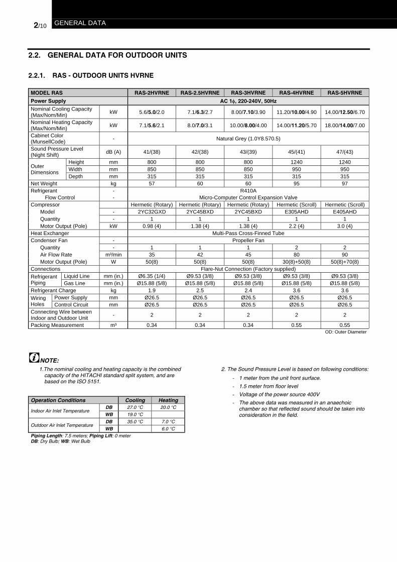
2.2. GENERAL DATA FOR OUTDOOR UNITS
2.2.1. RAS - OUTDOOR UNITS HVRNE
MODEL RAS RAS-2HVRNE RAS-2.5HVRNE RAS-3HVRNE RAS-4HVRNE RAS-5HVRNE
Power Supply AC 1φ, 220-240V, 50HzNominal Cooling Capacity(Max/Nom/Min) kW 5.6/5.0/2.0 7.1/6.3/2.7 8.00/7.10/3.90 11.20/10.00/4.90 14.00/12.50/6.70
Nominal Heating Capacity(Max/Nom/Min) kW 7.1/5.6/2.1 8.0/7.0/3.1 10.00/8.00/4.00 14.00/11.20/5.70 18.00/14.00/7.00
Cabinet Color(MunsellCode) - Natural Grey (1.0Y8.570.5)
Sound Pressure Level(Night Shift) dB (A) 41/(38) 42/(38) 43/(39) 45/(41) 47/(43)
Height mm 800 800 800 1240 1240Width mm 850 850 850 950 950Outer
DimensionsDepth mm 315 315 315 315 315
Net Weight kg 57 60 60 95 97Refrigerant - R410A
Flow Control - Micro-Computer Control Expansion ValveCompressor Hermetic (Rotary) Hermetic (Rotary) Hermetic (Rotary) Hermetic (Scroll) Hermetic (Scroll)
Model - 2YC32GXD 2YC45BXD 2YC45BXD E305AHD E405AHDQuantity - 1 1 1 1 1Motor Output (Pole) kW 0.98 (4) 1.38 (4) 1.38 (4) 2.2 (4) 3.0 (4)
Heat Exchanger Multi-Pass Cross-Finned TubeCondenser Fan - Propeller Fan
Quantity - 1 1 1 2 2Air Flow Rate m³/min 35 42 45 80 90Motor Output (Pole) W 50(8) 50(8) 50(8) 30(8)+50(8) 50(8)+70(8)
Connections Flare-Nut Connection (Factory supplied)Liquid Line mm (in.) Ø6.35 (1/4) Ø9.53 (3/8) Ø9.53 (3/8) Ø9.53 (3/8) Ø9.53 (3/8)Refrigerant
Piping Gas Line mm (in.) Ø15.88 (5/8) Ø15.88 (5/8) Ø15.88 (5/8) Ø15.88 (5/8) Ø15.88 (5/8)Refrigerant Charge kg 1.9 2.5 2.4 3.6 3.6
Power Supply mm Ø26.5 Ø26.5 Ø26.5 Ø26.5 Ø26.5WiringHoles Control Circuit mm Ø26.5 Ø26.5 Ø26.5 Ø26.5 Ø26.5Connecting Wire betweenIndoor and Outdoor Unit - 2 2 2 2 2
Packing Measurement m³ 0.34 0.34 0.34 0.55 0.55OD: Outer Diameter
NOTE:1.The nominal cooling and heating capacity is the combined
capacity of the HITACHI standard split system, and arebased on the ISO 5151.
Operation Conditions Cooling HeatingDB 27.0 °C 20.0 °C
Indoor Air Inlet TemperatureWB 19.0 °C
DB 35.0 °C 7.0 °COutdoor Air Inlet Temperature
WB 6.0 °C
Piping Length: 7.5 meters; Piping Lift: 0 meterDB: Dry Bulb; WB: Wet Bulb
2. The Sound Pressure Level is based on following conditions:
- 1 meter from the unit front surface.
- 1.5 meter from floor level
- Voltage of the power source 400V
- The above data was measured in an anaechoicchamber so that reflected sound should be taken intoconsideration in the field.

DIMENSIONAL DATA 3/19
3.2. OUTDOOR UNITS MODELS
3.2.1. MODELS: RAS-(2~3)H(V)RNE / HN(V)EUnits: mm
Mark Name Remarks
1 Service Cover -
2 Refrigerant Gas LinePiping Connectionwith Ø15.88 mm Flare Nut
3 Refrigerant Liquid LinePiping Connectionwith Ø9.53 mm Flare Nut
4 Hole for Refrigerant Piping (Knockout-Hole)5 Hole for Control Line Wiring Ø26.5 Knockout-Hole6 Hole for Condensate Drain (Ø26)7 Hole for Condensate Drain (4-Ø24)8 Hole for Power Supply Wiring Ø26.5 Knockout-Hole9 2-U Cut Holes -
10 4-Holes for fixing the unit to thewall (Both sides) (M5 Tapping Screw)
NOTES:1. If there are no walls in front or behind the unit, a
service space of 600 mm for the front and 200 mm forthe rear is still required.
2. If there are walls around the unit, then vent holesmust be made through the wall.
3. When there are obstacles above the unit, the foursurrounding sides must be kept open.
Service Space
3/20 DIMENSIONAL DATA
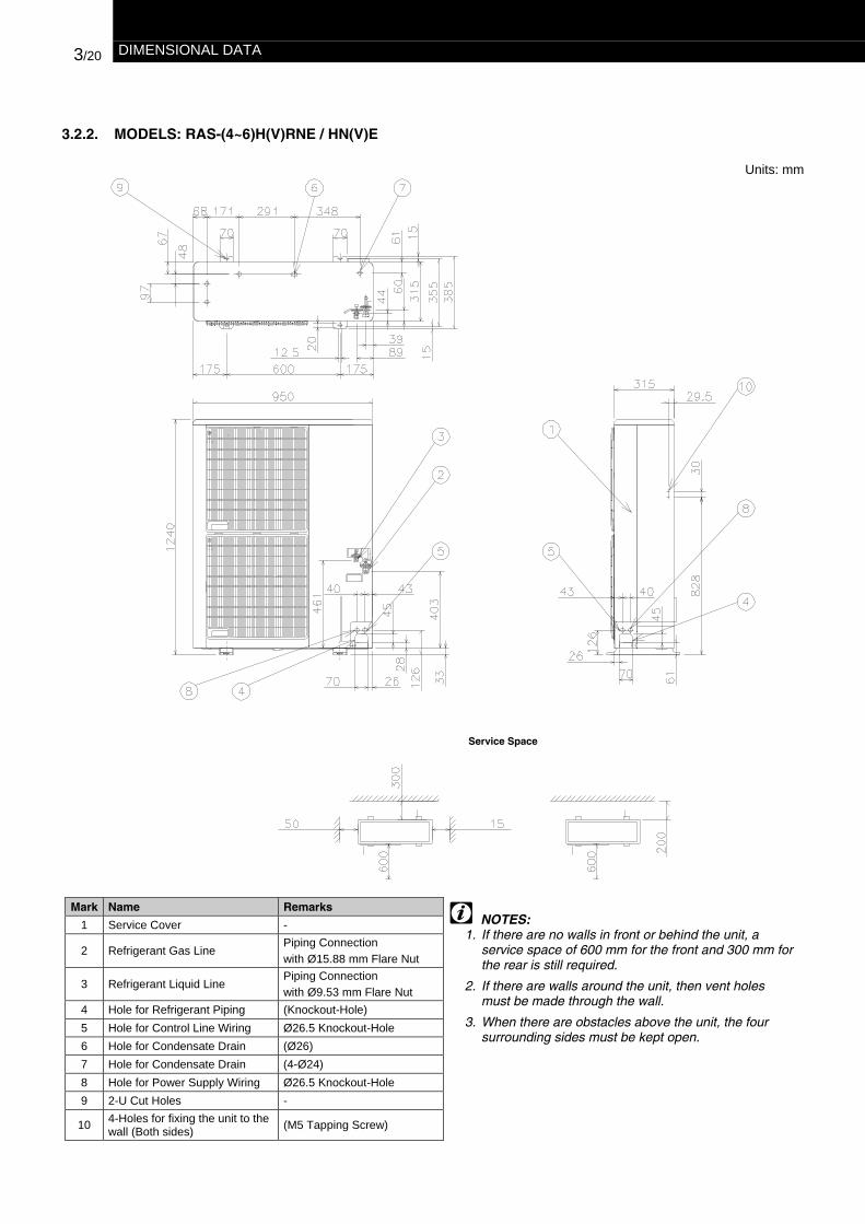
3.2.2. MODELS: RAS-(4~6)H(V)RNE / HN(V)E
Units: mm
Mark Name Remarks
1 Service Cover -
2 Refrigerant Gas LinePiping Connectionwith Ø15.88 mm Flare Nut
3 Refrigerant Liquid LinePiping Connectionwith Ø9.53 mm Flare Nut
4 Hole for Refrigerant Piping (Knockout-Hole)5 Hole for Control Line Wiring Ø26.5 Knockout-Hole6 Hole for Condensate Drain (Ø26)7 Hole for Condensate Drain (4-Ø24)8 Hole for Power Supply Wiring Ø26.5 Knockout-Hole9 2-U Cut Holes -
10 4-Holes for fixing the unit to thewall (Both sides) (M5 Tapping Screw)
NOTES:1. If there are no walls in front or behind the unit, a
service space of 600 mm for the front and 300 mm forthe rear is still required.
2. If there are walls around the unit, then vent holesmust be made through the wall.
3. When there are obstacles above the unit, the foursurrounding sides must be kept open.
Service Space

DIMENSIONAL DATA 3/21
3.2.3. MODELS: RAS-(8~12)HRNE
Units: mm
Mark Name Remarks
1 Service Cover2 Electrical Control Box
3 Refrigerant Gas Line
Piping ConnectionWith 19.05 mm Flare Nut (8 HP)With 22.20 mm BrazingFlange (10 HP)
4 Refrigerant Liquid LinePiping Connectionwith Ø9.53 mm Liquid Line
5 Holes for Refrigerant Piping 220×60 mm6 Hole for Control Line Wiring Ø26 x 2 mm7 Hole for Power Supply Wiring Ø56 mm8 Hole for Condensate Drain Ø26 x 4 mm9 Hole for Power Supply Wiring Ø52 mm
10 Holes for fixing to the floor 4
NOTES:1. If there is wall behind the unit higher than 500 mm,
then the air intake space required at the rear of theunit is 300 + H/2 mm.
2. If there are no walls in front or behind the unit, aservice space of 500 mm for the front and 300 mm forthe rear is still required.
3. If there are walls around the unit, then vent holes mustbe made through the wall.
4. When there are obstacles above the unit, the foursurrounding sides must be kept open.
Service Space

9/2 REFRIGERANT PIPING AND REFRIGERANT CHARGE
9.1. REFRIGERANT PIPING WORK RANGE
The piping selection and distribution must be designed considering the following specifications:
WARNING:The liquid piping and the gas piping must be thesame piping length and run along the same route.
Install Multi-Kits (Optional Accessory as system parts)must be used for the branch pipe to the Indoor Unit.
Install Multi-Kits at the same horizontal level.
Oil trap every Ht of height difference for gas pipingbetween Indoor Unit and Outdoor Unit is requiredwhen Outdoor Unit is located higher than the IndoorUnits for 8~12HRNE
However, in case that the Outdoor Unit is locatedlower than Indoor Unit, it is not required to put oil trapin the suction gas piping, since the oil in the systemcan return to the compressor due to the oil returncontrol system.
RAS-(2~6)H(V)RNE / HN(V)E
ITEM Maximum ApplicableRange H(V)RNE
Description Mark 2HP 2.5/3HP 4~6HpTotal length from OU to all IU - 55 m 60 m 77 mHeight difference (Hi-o) between OU to IU (*) Hi-o 30 mHeight difference (Hi-o) between IU to OU Hi-o 20 mHeight difference (Hi) between IUs Hi 0.5 m
IU: Indoor UnitOU: Outdoor Unit
ITEM Maximum ApplicableRange HN(V)E
Description Mark 2.5~5 HPTotal length from OU to all IU - 50 mHeight difference (Hi-o) between OU to IU (*) Hi-o 30 mHeight difference (Hi-o) between IU to OU Hi-o 20 mHeight difference (Hi) between IUs Hi 0.5 m
IU: Indoor UnitOU: Outdoor Unit
NOTEAfter branch pipe the piping length should be shorter than 10 mAll branch pipe should be balanced, the difference betweenthem can not bigger than 8 m or 6 m for a Triple case.
RAS-(8~12)HRNE
ITEM Maximum ApplicableRange HRNE
Description Mark 8~12 HPTotal length from OU to all IU - 120 mHeight difference (Hi-o) between OU to IU (*) Hi-o 30 mHeight difference (Hi-o) between IU to OU Hi-o 20 mHeight difference (Hi) between IUs Hi 0.5 mOil Trap every (Ht) meters of height Ht 10 m
IU: Indoor UnitOU: Outdoor Unit
NOTEAfter branch pipe the piping length should be shorter than 10 mAll branch pipe should be balanced, the difference betweenthem can not bigger than 8 m or 6 m for a Triple case.Make a Trap according to height difference (Ht) between IndoorUnit and Outdoor Unit. (See Table)
Outdoor Unit
Indoor Units
InstallMulti-Kitshorizontally
Outdoor Unit
Indoor Units
InstallMulti-Kitshorizontally
Trap(Refrigerantpiping atGas Side)

REFRIGERANT PIPING AND REFRIGERANT CHARGE 9/3
9.1.1. REFRIGERANT PIPING LENGTH
The refrigerant piping between the indoor unit and theoutdoor unit should be designed using the following chart.
Keep the design point within the dark area of the chart,which is showing the applicable height difference accordingto piping length.In case that a piping length is shorter than 5 meters,contact the Hitachi dealer.
NOTE (Only RAS-8~12)1. DSW: Dip Switch on Outdoor Unit PCB.
(DSW3 must be set when the Outdoor Unit is installed higher than Indoor Unit).
Piping Length specification:
RAS-2~3H(V)RNE
Heightdifference
(m)
Total length betweenOutdoor Unit and each
Indoor Unit L(m)
When theOutdoor unit isinstalledheigher thanIndoor Unit
When theOutdoor unit isinstalled lowerthan IndoorUnit
(*)-RAS-2HP(**)-RAS-3HP
RAS-4~6H(V)RNE
Heightdifference
(m)
Total length betweenOutdoor Unit and each
Indoor Unit L(m)
When theOutdoor unit isinstalledheigher thanIndoor Unit
When theOutdoor unit isinstalled lowerthan IndoorUnit
RAS-8~12HRNEHeight
difference(m)
Total length between Outdoor Unitand each Indoor Unit
L(m)
When theOutdoor unit isinstalledheigher thanIndoor Unit
When theOutdoor unit isinstalled lowerthan IndoorUnit
RAS-2.5~5HN(V)EHeight
difference(m)
Total length betweenOutdoor Unit and each
Indoor Unit L(m)
When theOutdoor unit isinstalledheigher thanIndoor Unit
When theOutdoor unit isinstalled lowerthan IndoorUnit
9.1.2. REFRIGERANT PIPING SELECTION
Select the piping connection sizes according to the following procedures:- Between Outdoor Unit and branch pipe:
- Select the same pipe connection size as the pipe size of the Outdoor Unit
- Between branch pipe and Indoor Unit:
- Select the same pipe connection size as the pipe size of the Indoor Unit
Piping connection size of Outdoor Unit, Indoor Unit & Distributor
Outdoor Unit Pipe Size Branch PipeSerie (HP) Gas Pipe Liquid Pipe Twin Triple Quad
2.0 15.88 (5/8) 9.53 (3/8) - - -2.5 15.88 (5/8) 9.53 (3/8) - - -3.0 15.88 (5/8) 9.53 (3/8) TE-03N - -4.0 15.88 (5/8) 9.53 (3/8) TE-04N - -5.0 15.88 (5/8) 9.53 (3/8) TE-56N - -6.0 15.88 (5/8) 9.53 (3/8) TE-56N TRE-06N -8.0 25.4 (1) 9.53 (3/8) TE-08N TRE-810N QE-810N10.0 25.4 (1) 12.7 (1/2) TE-10N TRE-810N QE-810N
H(V)RNEHN(V)E
12.0 25.4 (1) 12.7 (1/2) TE-10N TRE-810N QE-810N

6/2 ELECTRICAL DATA
6.1. INDOOR UNITS
All applicable Models:
Unit Main Power Applicable Voltage (V) Indoor Fan MotorModel
U PH Hz Max. Min. PH RNCI(A) IPTI(KW)RCIM-1.5 FSN 0.4 0.08RCIM-2.0 FSN 0.4 0.08RCI-1.5 FSN1E 0,2 0,05RCI-2.0 FSN1E 0,2 0,05RCI-2.5 FSN1E 0,3 0,06RCI-3.0 FSN1E 0,4 0,09RCI-4.0 FSN1E 0,7 0,11RCI-5.0 FSN1E 0,8 0,14
Cassette Type
RCI-6.0 FSN1E
230 1 50 253 207 1
1,0 0,18RCD-1.5 FSN 0,4 0,07RCD-2.0 FSN 0,4 0,09RCD-2.5 FSN 0,5 0,10RCD-3.0 FSN 0,6 0,12RCD-4.0 FSN 0,6 0,13
2-Way CassetteType
RCD-5.0 FSN
230 1 50 253 207 1
0,9 0,19RPC-2.0 FSNE 0,6 0,14RPC-2.5 FSNE 0,7 0,15RPC-3.0 FSNE 0,8 0,17RPC-4.0 FSNE 0,8 0,18RPC-5.0 FSNE 1,1 0,23
Ceiling Type
RPC-6.0 FSNE
230 1 50 253 207 1
1,1 0,23RPI-1.5 FSNE 0,6 0,10RPI-2.0 FSNE 0,9 0,21RPI-2.5 FSNE 1,1 0,24RPI-3.0 FSNE 1,2 0,26RPI-4.0 FSNE 1,2 0,26RPI-5.0 FSNE 1,8 0,38RPI-6.0 FSNE 1,8 0,38RPI-8.0 FSNE 4.7 1.01
In-the-Ceiling Type
RPI-10.0 FSNE
230 1 50 253 207 1
5.2 1.15RPK-1.5FSN1M 0,2 0,03RPK-1.5 FSNM 0,3 0,03RPK-2.0 FSNM 0,3 0,03RPK-2.5 FSNM 0,7 0,09RPK-3.0 FSNM 0,7 0,09
Wall Type
RPK-4.0 FSNM
230 1 50 253 207 1
0,7 0,09RPF-1.5 FSNE 0,2 0,04RPF-2.0 FSNE 0,4 0,09Floor TypeRPF-2.5 FSNE
230 1 50 253 207 10,4 0,09
RPFI-1.5 FSNE 0,2 0,04RPFI-2.0 FSNE 0,4 0,09Floor Concealed
TypeRPFI-2.5 FSNE
230 1 50 253 207 10,4 0,09
U: Supply Voltage (V)Hz: Frequency (Hz)RNC: Running Current Fan (A)IPT: Input Power Fan (kW)PH: Phase (φ)
NOTE:This data is based on the same conditions as thenominal capacity conditions. Refer to the notes ofthe Unit General data.
Specifications in these tables are subject tochange without notice in order that HITACHI maybring the latest innovations to their customers.

ELECTRICAL DATA 6/3
6.2. OUTDOOR UNITS
RAS-2~6HP
Unit Main Power Applicable Voltage Outdoor Unit(Including outdoor fan)
Cooling Operation Heating OperationModelU PH HZ Maximum Minimum PH STC
RNC IPT RNC IPT
MaximumCurrent
RAS-2HVRNE 253 207 1 6 5.5 1.24 5.8 1.32 21RAS-2.5HVRNE 253 207 1 7 7.1 1.56 7.2 1.62 21RAS-3HVRNE 253 207 1 6.5 10.7 2.16 11.9 2.41 25RAS-4HVRNE 253 207 1 10.5 15 3.07 15.3 3.13 32RAS-5HVRNE 253 207 1 15 19.2 3.94 20 4.11 32RAS-2.5HNVE 253 207 1 58 11.1 2.25 10.9 2.21 14RAS-3HNVE 253 207 1 68 12.1 2.40 11.7 2.32 15.3RAS-4HNVE
230 1 50
253 207 1 114 16.2 3.20 16.2 3.19 20RAS-4HRNE 440 360 3 10.5 3.8 2.49 3.8 2.44 11RAS-5HRNE 440 360 3 15 5.3 3.44 5 3.26 15RAS-6HRNE 440 360 3 15 6.5 4.21 6.3 4.05 15RAS-2.5HNE 440 360 3 27 4.9 2.25 4.9 2.21 5.7RAS-3HNE 440 360 3 27 5.2 2.40 5 2.40 5.9RAS-4HNE 440 360 3 48 6.9 3.20 6.9 3.20 7.4RAS-5HNE
400 3 50
440 360 3 74 9.2 4.22 9.3 4.29 10.2
RAS-8~12HPUnit Main
PowerAplicableVoltage Compressor Motor Outdoor Fan Motor
CoolingOperation
HeatingOperation
ModelU PH Hz Max. Min. PH STC
RNC IPT RNC IPTPH RNC IPT
MaximumCurrent
RAS-8HRNE 440 360 3 77,3 10,3 6.50 8,9 5.70 1 1,2 0,26 14RAS-10HRNE 440 360 3 80,8 12,5 7.90 12,4 7.80 1 2,2 0,5 17RAS-12HRNE
400 3 50440 360 3 88 12.5 10.64 13.2 11.13 1 2.2 0.5 17
U: Supply voltage (V)Hz: Frequency (Hz)STC: Starting Current (A)RNC: Running Current (A)IPT: Input Power (KW)PH: Phase (φ)
NOTE:This data is based on the same conditions as thenominal capacity conditions. Refer to the notes of theUnit General Data.Specifications in these tables are subject to changewithout notice in order that HITACHI may bring thelatest innovations to their customers.
NOTE:1. The above performance data is based on 5 m
equivalent piping length and 0 m piping lift.
2. The models RAS-2~6H(V)RNE are equipped with oneinverter-driven compressor.The models RAS-2.5~5H(V)NE are equipped with one,ON/OFF controlled compressor.The models RAS-8~12HRNE are equipped with oneinverter-driven compressor and one, ON/OFF controlledcompressor.

10/8 ELECTRICAL WIRING
Main switches protectionSelect the main switches according to the next table
INDOOR UNITS:
Model Power Source Max. Current CB ELBno. poles/A/mA
All indoor units 5 A 6 ARPI-8~10FSNE 230V/1φ/50Hz 10 A 15 A 2/40/30
ELB: Earth leakage breakerCB: Circuit breaker
OUTDOOR UNITS:
Model Power Source Max. Current CB ELBno. poles/A/mA
RAS-2HVRNE 21 A 25 ARAS-2.5HVRNE 21 A 25 ARAS-3HVRNE 21 A 25 ARAS-4HVRNE 28 A 32 ARAS-5HVRNE 29 A 32 ARAS-2.5HNVE 18 A 20 ARAS-3HNVE 21 A 25 ARAS-4HNVE
230V/1φ/50Hz
30 A 32 A
2/40/30
RAS-4HRNE 11 A 16 ARAS-5HRNE 15 A 20 ARAS-6HRNE 15 A 20 ARAS-8HRNE 14 A 16 ARAS-10HRNE 17 A 20 ARAS-12HRNE 17 A 20 ARAS-2.5HNE 6 A 10 ARAS-3HNE 8 A 10 ARAS-4HNE 11 A 16 ARAS-5HNE
400V/3φ/50Hz
14 A 16 A
4/40/30
ELB: Earth leakage breakerCB: Circuit breaker
10.5 H-LINK SYSTEM
NOTE:The H-LINK system cannot be applied to the cyclewith the old unit models or with the units that havean old transmission.
1. ApplicationThe H-LINK wiring system requires only two (2)transmission wires connecting each indoor unit andoutdoor unit for up to 16 refrigerant cycles, andconnecting wires for all indoor units and all outdoorunits in series.
The CS-NET is a complementary software that providesa total centralized control over the system.
The H-LINK system can be applied to the followingmodels.
Indoor unit Outdoor unitRCIRCIMRCDRPIRPKRPFRPFIRPC
RAS-H(V)RNERAS-HN(V)E
2. Features- The total wiring length is remarkably reduced.- Only one (1) connection is required for the wiring
between the indoor unit and outdoor unit.- The wiring connection to the complementary central
controllers devices is easy.
Example of H-LINK System:
Outdoorunit
Transmissioncables
Refrigerant piping
Indoor units
CS-NET: One refrigerant cycle
ELECTRICAL WIRING 10/7
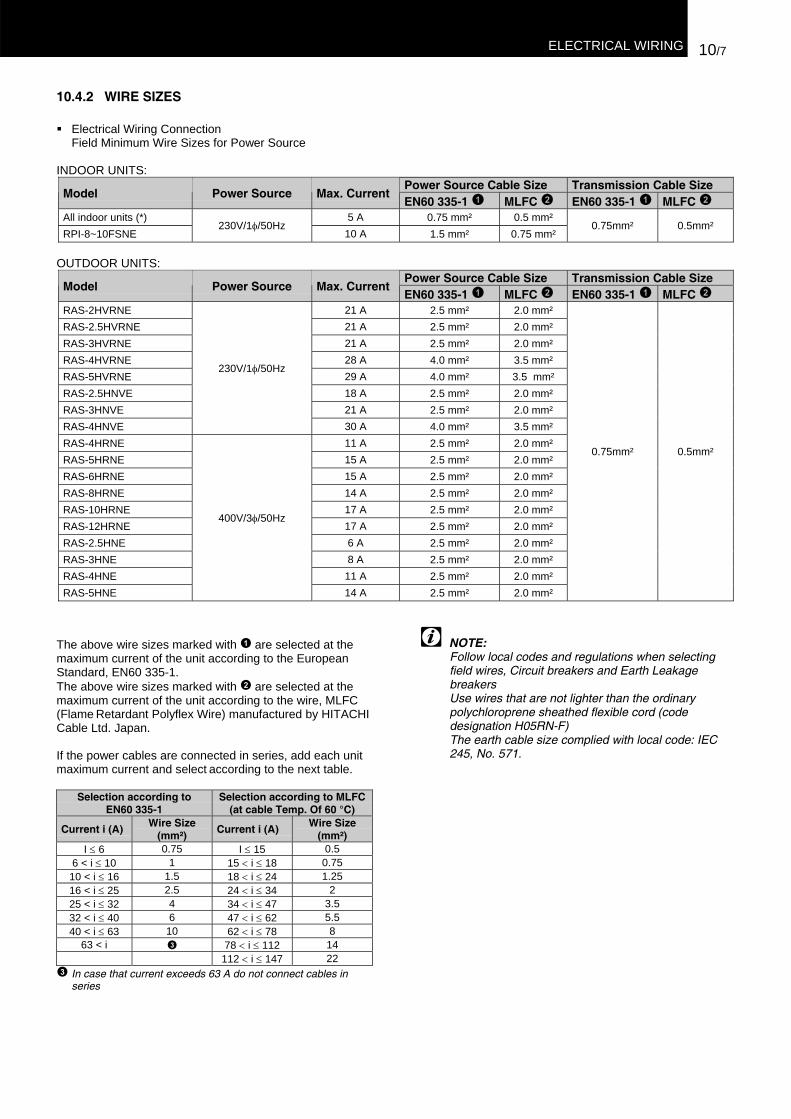
10.4.2 WIRE SIZES
Electrical Wiring ConnectionField Minimum Wire Sizes for Power Source
INDOOR UNITS:Power Source Cable Size Transmission Cable Size
Model Power Source Max. CurrentEN60 335-1 MLFC EN60 335-1 MLFC
All indoor units (*) 5 A 0.75 mm² 0.5 mm²RPI-8~10FSNE
230V/1φ/50Hz10 A 1.5 mm² 0.75 mm²
0.75mm² 0.5mm²
OUTDOOR UNITS:Power Source Cable Size Transmission Cable Size
Model Power Source Max. CurrentEN60 335-1 MLFC EN60 335-1 MLFC
RAS-2HVRNE 21 A 2.5 mm² 2.0 mm²RAS-2.5HVRNE 21 A 2.5 mm² 2.0 mm²RAS-3HVRNE 21 A 2.5 mm² 2.0 mm²RAS-4HVRNE 28 A 4.0 mm² 3.5 mm²RAS-5HVRNE 29 A 4.0 mm² 3.5 mm²RAS-2.5HNVE 18 A 2.5 mm² 2.0 mm²RAS-3HNVE 21 A 2.5 mm² 2.0 mm²RAS-4HNVE
230V/1φ/50Hz
30 A 4.0 mm² 3.5 mm²RAS-4HRNE 11 A 2.5 mm² 2.0 mm²RAS-5HRNE 15 A 2.5 mm² 2.0 mm²RAS-6HRNE 15 A 2.5 mm² 2.0 mm²RAS-8HRNE 14 A 2.5 mm² 2.0 mm²RAS-10HRNE 17 A 2.5 mm² 2.0 mm²RAS-12HRNE 17 A 2.5 mm² 2.0 mm²RAS-2.5HNE 6 A 2.5 mm² 2.0 mm²RAS-3HNE 8 A 2.5 mm² 2.0 mm²RAS-4HNE 11 A 2.5 mm² 2.0 mm²RAS-5HNE
400V/3φ/50Hz
14 A 2.5 mm² 2.0 mm²
0.75mm² 0.5mm²
The above wire sizes marked with are selected at themaximum current of the unit according to the EuropeanStandard, EN60 335-1.The above wire sizes marked with are selected at themaximum current of the unit according to the wire, MLFC(Flame Retardant Polyflex Wire) manufactured by HITACHICable Ltd. Japan.
If the power cables are connected in series, add each unitmaximum current and select according to the next table.
Selection according toEN60 335-1
Selection according to MLFC(at cable Temp. Of 60 °C)
Current i (A) Wire Size(mm²)
Current i (A) Wire Size(mm²)
I ≤ 6 0.75 I ≤ 15 0.56 < i ≤ 10 1 15 < i ≤ 18 0.75
10 < i ≤ 16 1.5 18 < i ≤ 24 1.2516 < i ≤ 25 2.5 24 < i ≤ 34 225 < i ≤ 32 4 34 < i ≤ 47 3.532 < i ≤ 40 6 47 < i ≤ 62 5.540 < i ≤ 63 10 62 < i ≤ 78 8
63 < i 78 < i ≤ 112 14112 < i ≤ 147 22
In case that current exceeds 63 A do not connect cables inseries
NOTE:Follow local codes and regulations when selectingfield wires, Circuit breakers and Earth LeakagebreakersUse wires that are not lighter than the ordinarypolychloroprene sheathed flexible cord (codedesignation H05RN-F)The earth cable size complied with local code: IEC245, No. 571.