s-series battery management system (bms) data sheetthe jtt s-series battery management system (bms)...
TRANSCRIPT

DN000092.E © 2012 JTT ELECTRONICS LTD
S-SERIES BATTERY MANAGEMENT SYSTEM (BMS)
Data Sheet
4 – 48 Cell Battery Pack Monitoring and Control, Passive Cell
Balancing, CAN, RS-232, Digital and Analog I/O, Ultra-Low
Power Dissipation with Hardware Interlock Safety Layer

S-SERIES BMS
2
DN000092.E © 2012 JTT ELECTRONICS LTD
1 FEATURES
Measures 4 to 48 cell voltages in series
Measures 4 to 48 cell temperatures
12 – 200V Battery Packs
300mA Passive Cell Balancing
State of Charge, State of Health, Capacity, DC
Resistance calculations
Cell over voltage, under voltage, and high
temperature hardware interlock layer
protection
Isolated CAN and isolated RS-232
Additional Digital and Analog I/O
Battery Relay and pre-charge control
Current Sensor Monitoring
12 – 24V Power Supply Input
Fault Management and Diagnostics
Data Logging
Ultra Low Power Dissipation
Automotive Grade
2 DESCRIPTION
The JTT S-Series Battery Management System (BMS) controllers are stand-alone Low Voltage Battery Control Systems. This all in one, single BMS controller can monitor battery packs up to 48 cells and 200V.
The S-Series controllers come in 4 different models: S1, S2, S3, and S4. The S1 can monitor 12 cells, S2 can monitor 24 cells, the S3 can monitor 36 cells, and the S4 can monitor 48 cells. Each bank of 12 cells monitors 12 cell voltages and 12 temperatures.
The S-Series balances the voltage and charge between all cells the battery pack by passive balancing. Energy is discharged from the highest charged cells in the pack, and thus maximizes the range of a battery pack and extends its life. The cell balancing is based on the amount of charge in each cell and not the cell voltage, and so balancing is active continuously during operation and not just during idle periods.
An intelligent software system runs more than 80 diagnostics at faster than 10 times a second, on both the cells and the entire battery pack. Most diagnostics are to ensure safe operation of the
battery pack, and the rest are for monitoring battery performance and life.
Each S-Series controller communicates over isolated CAN bus and isolated RS-232 all battery fault conditions, cell status, and battery data to either a Display, Monitoring System, vehicle ECU or a Motor Controller depending on the end application.
In addition, the S-series controllers are equipped with 6 additional I/O signals. Four dedicated Digital I/O ports and two configurable ports that are Digital Outputs by default but can be selected as Analog Outputs if required. The four Digital I/O's can either control various system peripherals or receive system inputs. The Analog Outs can be set to represent various battery parameter values.
The S-Series controller is designed to disconnect safety relays to isolate the battery in extreme operating conditions to ensure safe operation. The S-Series controller is compatible for all lithium cell chemistries such as LFP, NMC, LMO, LTO and all cell form factors such as pouch, cylindrical, or prismatic form.
3 APPLICATIONS
Electric, Hybrid, and Plug-In Hybrid Vehicles
Industrial Battery Packs
Backup and Standby Battery Systems

S-SERIES BMS
3
DN000092.E © 2012 JTT ELECTRONICS LTD
4 PRODUCT LINE
DEVICE
NUM OF CELLS NUM OF TEMPERATURES CAN
RS-232
CURRENT SENSOR
RELAYS DRIVERS
DIGITAL & ANALOG I/O
HARDWARE INTERLOCKS MIN MAX
S1 4 12 12 Y Y Y 2 6 Y
S2 8 24 24 Y Y Y 2 6 Y
S3 12 36 36 Y Y Y 2 6 Y
S4 16 48 48 Y Y Y 2 6 Y
Figure 1. S-Series Product Lineup
5 OPERATIONS
Cell Voltage Monitoring of 4 to 48 cells for the
entire S-Series. Cell voltage is sampled every 50ms to ensure fast response in protecting cells from brief over and under voltage events. Cell monitoring has 1.5mV resolution and less than 0.25% error.
Temperature monitoring of 4 to 48 temperature sensors to ensure the safety of the battery pack is always maintained and the lifetime of the cells is maximized by avoiding high temperature events that will deteriorate the cell`s performance.
Cell level calculated State of Charge (SOC). SOC dynamically calculated with advanced self-correcting model based algorithms. Less than 3 – 5% SOC error depending on the cell chemistry.
SOC algorithms adapt to changing cell characteristics over time as the cells in the battery age.
Safety Hardware Interlocks: cell over voltage, cell under voltage, and high cell temperature will trigger the hardware interlock and open the safety relays independently of the software system. This safety-critical system eliminates any events that could cause financial damage, injury, or loss of life without relying on the complexities or timing delays of the software system. The hardware system is designed for compatibility with IEC 61508 / ISO 26262.
The safety hardware interlock layer functions as a second layer to the software controls forming dual-channel architecture as required in safety-
S1
S2
S3
S4
S-SERIES BMS
4
DN000092.E © 2012 JTT ELECTRONICS LTD
critical systems. This has the advantage of detecting faults or failures even if a systematic fault has occurred in the software controls. JTT’s dual-channel architecture with hardware and software levels meets all safety critical system requirements. It minimizes controller cost and space when compared to other approaches used in other BMS systems where two independent but identical software systems are running in parallel.
State of Health (SOH) continually calculated and monitored, and is based on the capacity fade and internal resistance increase over the lifetime of the battery.
Cell Internal DC Resistance calculated for each cell and determines the charge rate limits, available power, and current forecasting.
Passive Balancing eliminates cell to cell imbalance by discharging energy at 300 mA from the highest charged cells. This maximizes battery capacity to extend the battery operational range, and extends battery lifetime by avoiding overcharging the weak cells. Continuous cell balancing during operation based on cell SOC
Isolated CAN communication with external systems and other diagnostic equipment. 2.5 kV RMS signal and power isolation and > 25 kV/us common-mode transient immunity.
Reliable Power Supply Input compatible for 12 and 24V systems with high voltage, low voltage, reverse voltage protection, high voltage transient immunity, load dump, and current injection immunity.
Fault Management: Over 80 fault conditions continually monitored and status reported over CAN. Multiple levels alarms: warning, soft shutdown, hard shutdown, sensor faults, and service alarms are all configurable. Alarms include under and over cell voltage, low and high cell temperature, over charge, over discharge, sensor failures (voltage, temperature, and current), faulty mechanical connections on bus bars or cell terminals, and others.
Two relay drivers that can be used for the positive relay, negative relay, dc charging relay, pre-charge relay, or others. Each relay has optional feedback sensing that can be used to monitor the position of the relay for fault diagnostics.
Relays are used to isolate the battery from the system in extreme cases that could result in a dangerous situation. Capable of breaking over 2000A, and withstand voltages of greater than 2200 Vrms.
Battery current monitoring with a dual-range automotive grade current sensor, to ensure accurate SOC measurements both at low or high currents.
Battery Voltage monitoring
Safety Device Interlock: inertia switch, crash sensor, tilt switch, manual service disconnect (MSD)
Additional temperature input could be used for ambient air measurement.
Ability to control fans, pumps, heaters, and other components for battery thermal management. Control is based on configurable high and low temperature operating limits.
Isolated CAN and Isolated RS-232 for communication to the vehicle, motor controller, charger, LCD, or other device. One additional CAN for diagnostic purposes and firmware upgrading.
Six additional Digital and Analog I/O available and configurable to output battery parameters or control various battery components.
Battery Cell serial numbers can be set and stored in the controller during battery pack assembly, and useful for cell tracking for troubleshooting and warranty purposes.
Every Cell’s lifetime temperature, voltage, and current data is logged in the controller and may be useful for troubleshooting and warranty.
Internal controller temperature monitoring.

S-SERIES BMS
5
DN000092.E © 2012 JTT ELECTRONICS LTD
Cell balance circuitry has self-test capability to guarantee proper BMS operation and battery pack performance.
Ultra Low Cell Power Dissipation. The cell voltage monitoring and hardware interlock has 1.55 mA discharge per cell while actively monitoring and only 30 μA leakage while off. This is less than a third of the leakage from previous generation controllers.
In system firmware upgrading available through diagnostic CAN.
Battery and cell monitoring and diagnostics available in real-time through diagnostic CAN to PC/Laptop with BMS Link software tool.
Each bank of cell monitoring can support 4 – 12 cell voltages, and 1 – 12 cell temperature inputs.
IP55 protection rating.
Automotive grade electrical and mechanical components for temperature and vibration.
6 BLOCK DIAGRAM
SUPPLY POWER PROTECTION
ISOLATED CAN BUS
ISOLATED RS-232
DIGITAL I/O(X4)
ANALOG OUTPUT(X2)
SAFETY DEVICE INTERLOCK
TEMPERATURE SENSOR FILTER
CURRENT SENSORAMPLIFIER
RELAY DRIVERSWITH
FEEDBACK(X2)
HIGH VOLTAGE MONITOR
INPUTPROTECTION
CELL BALANCING
CELL VOLTAGE MONITOR
UNDER & OVER VOLTAGE HARDWARE
INTERLOCK
INPUTPROTECTION
CELL TEMPERATURE MONITOR
HIGH TEMPERATURE HARDWARE INTERLOCK
HARDWARE INTERLOCK
CONTROL
ENABLE
DATA LOGGING MEMORY
CEL
L V
OLT
AG
ES *
CEL
L TE
MP
ERA
TUR
ES *
COMMAND
HIGH
LOW
DRIVERS
FEEDBACK
DIAGNOSTIC CAN BUS
Figure 2. Controller Block Diagram
* Variable number of cell voltage and cell temperature inputs based on different S-Series Models
S-SERIES BMS
6
DN000092.E © 2012 JTT ELECTRONICS LTD
7 TYPICAL APPLICATION
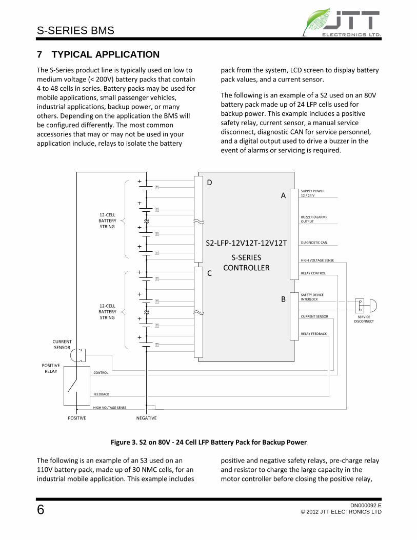
The S-Series product line is typically used on low to medium voltage (< 200V) battery packs that contain 4 to 48 cells in series. Battery packs may be used for mobile applications, small passenger vehicles, industrial applications, backup power, or many others. Depending on the application the BMS will be configured differently. The most common accessories that may or may not be used in your application include, relays to isolate the battery
pack from the system, LCD screen to display battery pack values, and a current sensor.
The following is an example of a S2 used on an 80V battery pack made up of 24 LFP cells used for backup power. This example includes a positive safety relay, current sensor, a manual service disconnect, diagnostic CAN for service personnel, and a digital output used to drive a buzzer in the event of alarms or servicing is required.
~~12-CELL BATTERY STRING
~~12-CELL BATTERY STRING
S2-LFP-12V12T-12V12T
S-SERIES CONTROLLER
SUPPLY POWER12 / 24 V
BUZZER (ALARM) OUTPUT
DIAGNOSTIC CAN
HIGH VOLTAGE SENSE
SAFETY DEVICE INTERLOCK
CURRENT SENSOR
RELAY CONTROL
RELAY FEEDBACK
B
A
D
C
POSITIVE RELAY
POSITIVE NEGATIVE
CURRENTSENSOR
CONTROL
FEEDBACK
HIGH VOLTAGE SENSE
SERVICE DISCONNECT
T
T
T
T
T
T
T
T
Figure 3. S2 on 80V - 24 Cell LFP Battery Pack for Backup Power
The following is an example of an S3 used on an 110V battery pack, made up of 30 NMC cells, for an industrial mobile application. This example includes
positive and negative safety relays, pre-charge relay and resistor to charge the large capacity in the motor controller before closing the positive relay,

S-SERIES BMS
7
DN000092.E © 2012 JTT ELECTRONICS LTD
current sensor, isolated RS-232 to communicate with a LCD screen displaying all BMS data, digital output used to control power to the LCD screen, digital output to control a relay to drive a fan for thermal management, isolated CAN to
communicate with an on-board battery charger, manual service disconnect, and a key switch input to change operating modes between normal mode and low-power.
~~10-CELL BATTERY MODULE
~~10-CELL BATTERY MODULE
S3-NMC-10V10T-10V10T-10V10T
S-SERIES CONTROLLER
SUPPLY POWER12 / 24 V
BUZZER (ALARM) OUTPUT
DIAGNOSTIC CAN
HIGH VOLTAGE SENSE
SAFETY DEVICE INTERLOCK
CURRENT SENSOR/4
RELAY CONTROL/4
RELAY FEEDBACK/4
B
A
D
C
POSITIVE RELAY
POSITIVE NEGATIVE
CURRENTSENSOR
CONTROL/2
FEEDBACK/2
HIGH VOLTAGE SENSE
SERVICE DISCONNECT
T
T
T
T
T
T
T
T
~~10-CELL BATTERY MODULE
E
T
T
T
T
NEGATIVERELAY
CONTROL/2
FEEDBACK/2
LCD SCREEN
ISOLATED RS-232TX / RX / GND
12V SOURCE
LCD POWER SWITCH
PW
RG
ND
RS-
23
2
KEYSWITCH INPUT
ON-BOARD BATTERY CHARGE
FAN
FAN OUTPUTFAN RELAY
FAN POWER
CONTROL
MOTOR CONTROLLER ENABLE OUTPUT
ISOLATED CAN
CAN COMMUNICATION
PRE-CHARGERELAY
PRE-CHARGERESISTOR
PRE-CHARGE RELAY OUTPUT
Figure 4. S3 on 110V - 30 Cell NMC Battery Pack, 3x 10 Cell Modules, Mobile Industrial Application

S-SERIES BMS
8
DN000092.E © 2012 JTT ELECTRONICS LTD
8 CONFIGURATIONS AVAILABLE
The S-Series controllers are available in a large number of pre-set configurations, and may be customized for any application.
The configurations vary based on number of battery cells in series to monitor and which chemistry the battery cells are.
Each monitoring “bank” must be configured for the correct number of cells in the application, from 4 to 12.
Each battery cell chemistry has different thresholds for cell under voltage and over voltage fault
conditions which are set in the hardware interlock circuitry.
The S-Series will work with any number of parallel cells, and with any cell capacity selected, as these require only a firmware configuration.
In addition to cell configuration, the controller can be customized if isolated CAN communication and/or isolated RS-232 communication is needed, and whether digital outputs 5 and 6 are required to be analog outputs instead. If CAN or RS-232 is not required then these features may not be included to minimize BMS power consumption even further.

S-SERIES BMS
9
DN000092.E © 2012 JTT ELECTRONICS LTD
9 MODEL NUMBERING
S__-____-__-__-__-__-____
Battery Cell ChemistryLFP – Lithium Iron PhosphateNMC – Nickel Manganese CobaltLMO – Lithium Manganese Oxide
Cells in Series first group of 12X – Specify 4 to 12 cells
S-Series Controller Number1 – 12 Cells2 – 24 Cells3 – 36 Cells4 – 48 Cells
Cells in Series second group of 12 (S2, S3, S4 only)X – Specify 4 to 12 cells
Cells in Series third group of 12 (S3, S4 only)X – Specify 4 to 12 cells
Cells in Series forth group of 12 (S4 only)X – Specify 4 to 12 cells
Additional Hardware FeaturesC – Isolated CAN CommunicationR – Isolated RS-232 CommunicationA – Two Analog Outputs (instead of digital i/o 5 and 6)
Example Model Number:
S3 controller to monitor 24 NMC cells, separated into 3 modules of 8 cells each. Isolated CAN and RS-232 included.
S3-NMC-8V-8V-8V-CR

S-SERIES BMS
10
DN000092.E © 2012 JTT ELECTRONICS LTD
10 ELECTRICAL CHARACTERISTICS
PARAMETER MIN TYP MAX UNITS
Supply Power Specifications
Supply Voltage (Vmain) 9 12 / 24 32 V
Supply Voltage Under voltage Cut-out (while operating) 7.7 V
Supply Voltage Over voltage Cut-out (while operating) 33.0 V
Supply Current, Active Mode ( @ 24V )
Default Configuration (No CAN or RS-232) 25 mA
With Isolated CAN 30 mA
With Isolated RS-232 55 mA
With both isolated CAN & isolated RS-232 60 mA
Supply Current, Idle (Low Power) Mode ( @ 24V ) 5.0 mA
Cell Voltage Monitoring and Hardware Interlock Specifications
Measurement Resolution 1.5 mV
Measurement Offset -0.5 0.5 mV
Measurement Gain Error -0.12 0.12 %
Cell Voltage Range 0 5 V
Cell Monitoring Current (In/Out Pins Cell 1 to Cell 12)
Active Measuring -20 20 μA
Leakage 2 nA
Cell Monitoring Supply Current (In Cell12 Out Cell 0)
Active Measuring 1.22 1.53 2.00 mA
Leakage 23 30 42 μA
Measurement Period 50 ms
Hardware Interlock Detection Level Error -0.8 0.8 %
Hardware Interlock Detection Period 13 15.5 19 ms
Cell Temperature Monitoring Specifications
Measurement Resolution 0.1 °C
Measurement Accuracy 1.0 %
Cell Temperature Range -100.0 100.0 °C
Cell Balancing Specifications
Passive Balancing Current 250 300 mA
Isolated CAN Communication Specifications
Isolation 2.5 kV rms
Common-mode Transient Immunity 25 kV/μs
Recessive Bus Voltage 2.0 3.0 V
CANH Output Voltage 2.75 4.5 V
CANL Output Voltage 0.5 2.0 V
Maximum Data Rate 1 Mbps
Diagnostic CAN Communication Specifications
Recessive Bus Voltage 2.0 3.0 V
CANH Output Voltage 2.75 4.5 V

S-SERIES BMS
11
DN000092.E © 2012 JTT ELECTRONICS LTD
PARAMETER MIN TYP MAX UNITS
CANL Output Voltage 0.5 2.25 V
Data Rate 500 Kbps
Isolated RS-232 Communication Specifications
Rx Input Voltage Range -30.0 30.0 V
Rx Input Threshold Low 0.6 1.3 V
Rx Input Threshold High 1.6 2.4 V
Rx Input Resistance 3 5 7 kΩ
Tx Output Voltage ±5 ±5.7 V
Tx Output Resistance 300 Ω
Maximum Data Rate 460 kbps
Current Monitoring Specifications
Sensor Supply Voltage 4.9 5.0 5.1 V
Sensor Supply Current 100 mA
Low Channel Resolution* 1.2 mV
Low Channel Range* 0 5 V
Low Channel Error* 5 mV
High Channel Resolution* 1.2 mV
High Channel Range* 0 5 V
High Channel Error* 5 mV
Battery Voltage Monitoring Specifications
Range (Low Range Configuration) 0 60 V
Resolution (Low Range Configuration) 1.0 mV
Range (Medium Range Configuration) 0 120 V
Resolution (Medium Range Configuration) 1.8 mV
Range (High Range Configuration) 0 240 V
Resolution (High Range Configuration) 3.6 mV
Accuracy 0.1 %
Relay Specifications
Driver Output Voltage Vmain V
Driver Output Current - Continuous 600 mA
Driver Output Current – Pulse 4.0 A
Position Feedback Output Voltage 5 V
Digital I/O Specifications
Low Side Digital Output Current Sink Per Channel 750 mA
Low Side Digital Output Current Sink All Channels 2 A
Low Side Digital Output Current Source per Channel 0 mA
Low Side Digital Output Switching Voltage 60 V
Digital Input Active Low Level 0 0.7 V
Analog Output Specifications
Output Voltage Range 0 5 V
Output Voltage Resolution 1.2 mV
Output Voltage Accuracy -1.25 0.4 1.25 %
Output Voltage Settling Time 6 μs

S-SERIES BMS
12
DN000092.E © 2012 JTT ELECTRONICS LTD
PARAMETER MIN TYP MAX UNITS
Output Current 15 24 mA
Safety Device Hardware Interlock Specifications
Interlock Output Voltage 2.5 V
Interlock Output Source Current 20 mA
Interlock Return Non-Fault Condition 2.0 3.0 V
Ambient Temperature Sensor Specifications
Measurement Resolution 0.1 °C
Measurement Accuracy 1.0 %
Cell Temperature Range -45.0 100.0 °C
* See section on current sensor in the application information on resolution, accuracy, and range of measuring battery
current with recommended current sensor.
11 APPLICATION INFORMATION
MODES OF OPERATION
The S-Series controller has two modes of operation: Active and Idle. In active mode the controller is completing all required tasks. Idle mode is a power saving mode where all cell voltage and temperature monitoring circuits, external sensors, and all peripherals may be turned off. If required only the controller core and external communications (CAN and RS-232) are still operational. The controller can be configured to switch between idle and active mode by either a digital input, like a key switch type signal, or by communication commands, or timeout, over CAN or RS-232.
The functionality active in idle mode may be customized for a particular application. In some applications minimum power consumption is most important and so all monitoring and peripherals are powered down. In other applications, it may be more important to keep large capacity cells balanced and so cell voltage monitoring and cell balancing circuitry is still running in idle mode.
If idle mode is not required for the application then the power supply to the BMS may be turned on and off externally to start and stop the controller in active mode.
CONTROLLER STATE FLOW
The controller state flow, or how it functions, can be completely different for each battery application. It
can change drastically between batteries used for backup and standby power, batteries used in medium voltage industrial applications, to batteries used in high voltage automobiles. For this reason the S-Series controller state flow is customized for each customer’s application. In each state, different actuators can be commanded on or off. The following is a list of a few common controller states:
Self Test
Contactors Open
Pre-Charge
Contactors Closed – Normal Mode
Contactors Closed – Low Power Mode
Charging
Charge Complete
Idle
Cold or Hot Temperature Hibernation
RELAY CONTROL WITH PRE-CHARGE
Safety relay(s) are required to be installed on lithium batteries in order to disconnect the battery from the system, or vehicle in order to protect the battery and to avoid any dangerous conditions. For a battery system of 60 V or less a single relay on the positive on the battery may be used. For battery systems greater than 60V two relays should be used, one relay on the positive terminal and another on the negative terminal of the battery.
S-SERIES BMS
13
DN000092.E © 2012 JTT ELECTRONICS LTD
BATTERY
PRE-CHARGE
POSITIVE
NEGATIVE
SYSTEM
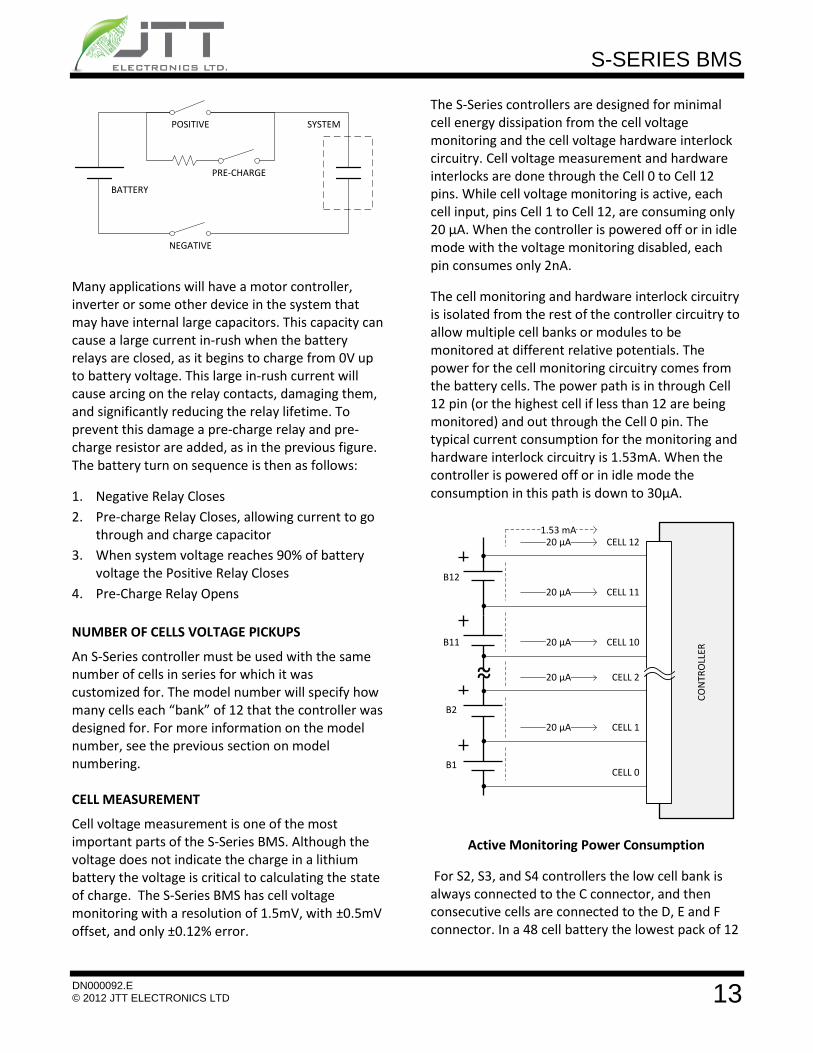
Many applications will have a motor controller, inverter or some other device in the system that may have internal large capacitors. This capacity can cause a large current in-rush when the battery relays are closed, as it begins to charge from 0V up to battery voltage. This large in-rush current will cause arcing on the relay contacts, damaging them, and significantly reducing the relay lifetime. To prevent this damage a pre-charge relay and pre-charge resistor are added, as in the previous figure. The battery turn on sequence is then as follows:
1. Negative Relay Closes
2. Pre-charge Relay Closes, allowing current to go through and charge capacitor
3. When system voltage reaches 90% of battery voltage the Positive Relay Closes
4. Pre-Charge Relay Opens
NUMBER OF CELLS VOLTAGE PICKUPS
An S-Series controller must be used with the same number of cells in series for which it was customized for. The model number will specify how many cells each “bank” of 12 that the controller was designed for. For more information on the model number, see the previous section on model numbering. CELL MEASUREMENT
Cell voltage measurement is one of the most important parts of the S-Series BMS. Although the voltage does not indicate the charge in a lithium battery the voltage is critical to calculating the state of charge. The S-Series BMS has cell voltage monitoring with a resolution of 1.5mV, with ±0.5mV offset, and only ±0.12% error.
The S-Series controllers are designed for minimal cell energy dissipation from the cell voltage monitoring and the cell voltage hardware interlock circuitry. Cell voltage measurement and hardware interlocks are done through the Cell 0 to Cell 12 pins. While cell voltage monitoring is active, each cell input, pins Cell 1 to Cell 12, are consuming only 20 μA. When the controller is powered off or in idle mode with the voltage monitoring disabled, each pin consumes only 2nA.
The cell monitoring and hardware interlock circuitry is isolated from the rest of the controller circuitry to allow multiple cell banks or modules to be monitored at different relative potentials. The power for the cell monitoring circuitry comes from the battery cells. The power path is in through Cell 12 pin (or the highest cell if less than 12 are being monitored) and out through the Cell 0 pin. The typical current consumption for the monitoring and hardware interlock circuitry is 1.53mA. When the controller is powered off or in idle mode the consumption in this path is down to 30μA.
1.53 mA
~~
B1
B2
B11
B12
CO
NTR
OLL
ER
CELL 0
CELL 1
CELL 2
CELL 10
CELL 11
CELL 12
20 μA
20 μA
20 μA
20 μA
20 μA
Active Monitoring Power Consumption
For S2, S3, and S4 controllers the low cell bank is always connected to the C connector, and then consecutive cells are connected to the D, E and F connector. In a 48 cell battery the lowest pack of 12

S-SERIES BMS
14
DN000092.E © 2012 JTT ELECTRONICS LTD
connects to C, and the highest pack of 12 connects to F.
CELL INPUT PROTECTION
The cell voltage monitoring inputs (Cell 0 to Cell 12) are capable of measuring 0 – 5 volts. However the inputs have added protection to both protect the BMS controller and to ensure that connected cells are not discharged in the event that some of the voltage inputs are miss-wired. Each cell input has reverse voltage and high voltage protection in case two wires are swapped.
If a wiring miss-match does occur, and the cell input protection is tripped, the protection will automatically reset itself once the cell input connector is unplugged and voltage is removed from the input pins. Extreme care must be taken to ensure that all cell voltage inputs are wired correctly.
PASSIVE CELL BALANCING
Cell balancing is achieved by discharging energy from the highest charged cells. Cell balancing is required to keep all cells within the battery pack equally charged. This ensures that cells that may have slightly weaker performance are not degraded further by over-charging or over-discharging them during operation. A well balanced battery pack will have higher capacity and a longer lifetime then an unbalanced one.
Depending on cell voltage the passive balance circuitry will discharge a balancing cell between 200 and 300 mA. The cell balancing is based on the amount of charge in each cell and not on the cell voltage. This means that balancing is active all the time unlike other BMS systems where balancing is only enabled while the battery is idle. The controller also monitors the internal balance circuitry temperature and may limit the number of balancing cells when operating in extreme ambient temperatures.
CELL VOLTAGE AND TEMPERATURE HARDWARE INTERLOCKS
Cell hardware interlocks based on cell over voltage, cell under voltage, and high cell temperature will
trigger the hardware interlock and open the safety relays independently of the software system. This safety-critical system eliminates any events that could cause financial damage, injury, or loss of life without relying on the complexities or timing delays of the software system. The hardware system is designed for compatibility with IEC 61508 / ISO 26262.
The safety hardware interlock layer functions as a second layer to the software controls forming dual-channel architecture as required in safety-critical systems. This has the advantage of detecting faults or failures even if a systematic fault has occurred in the software controls. JTT’s dual-channel architecture with hardware and software levels meets all safety critical system requirements. It minimizes controller cost and space when compared to other approaches used in other BMS systems where two independent but identical software systems are running in parallel.
SAFETY DEVICE HARDWARE INTERLOCK
The BMS has a single safety device hardware interlock (SDHI). This interlock comes out of the controller, can be wired through multiple devices in series, and then returns to the controller. The safety device hardware interlock output will source 2.5V. The safety device hardware interlock will fault if its input is less than 2V or higher than 3V. This will be triggered if any device in the circuit breaks the circuit, by opening the connection between the out and in. The interlock will also detect and trigger on failures of shorting to ground or to a higher voltage.
Multiple devices can be used to trigger the interlock by connecting them in series. Typical devices may include an Emergency Stop, manual service disconnect (MSD), inertia switch (crash sensor), tilt switch, or auxiliary feedback contacts in the battery positive and negative power connector. If there are no safety devices required then the SDHI input must be wired directly to the SDHI output.
BATTERY VOLTAGE MEASUREMENT
The battery voltage measurement circuitry can be configured in firmware for low, medium, and high ranges depending on the voltage of the battery

S-SERIES BMS
15
DN000092.E © 2012 JTT ELECTRONICS LTD
pack. The low range is from 0 to 60 V batteries, and has a resolution of 1.0 mV. The medium range is from 60 to 120 V batteries, and has a resolution of 1.8 mV. The high range is from 120 to 240 V, and has a resolution of 3.6 mV. All ranges have an accuracy of 0.1 %. The battery voltage measurement is taken on the system side of the safety relays. It is used for alarms, control of pre-charging the system, and to determine if a relay has failed open or closed without the relay position feedback.
SERIAL PORT (RS-232)
There is a single isolated RS-232 port that can be used to connect to an LCD screen, battery charger, or any other device that has RS-232. The port has standard RS-232 levels, and adheres to the EIA-232E standard.
Communication requires 3 wires: transmit (Tx), receive (Rx), and ground (GND). The direction of transmit and receive are relative to the S-Series controller. Baud rate may be configured for speeds such as 9600, 57600, or 115,200 bps. The maximum baud rate is 460,000 bps. The data bits, parity, and stop bits can be configured for each customer’s application. No hardware flow control is implemented.
CAN BUS
Isolated controller area network (CAN) bus compatible with SAE J1939 and ISO 11898. It is configurable to run at speeds up to 1 Mbps, although 250 or 500 kbps is recommended for automotive and industrial applications.
A CAN bus that complies with SAE J1939 and ISO 11898 requires termination resistors at each end of the cable, or linear bus. The bus should be linear and not star or other topologies. The standard termination is 120Ω between the CAN High and CAN Low cables, at each cable end. This layout results in the nominal 60Ω bus load.
The S-Series controller does not have end of line termination. It is meant to be added to an existing CAN bus as a node. It does however have over 2kΩ of resistance split between the incoming CAN high
and low to reduce electromagnetic emission and increase bus noise immunity.
For the CAN bus physical layer it is recommended to use shielded twisted pair cables with the shield terminated at one end. For all other physical layer recommendations please consult SAE J1939 and ISO 11898.
DIAGNOSTIC CAN BUS
A non-isolated controller area network (CAN) bus is implemented for diagnostic purposes and firmware upgrading. This CAN bus is meant to be connected through a CAN-USB device to your laptop or PC. Firmware upgrading may be completed with the JTT Firmware loader. BMS Link can be used to monitor and log all the battery and BMS data to your laptop for troubleshooting and servicing. This CAN bus does include the end of line 120Ω termination. It is configured to 500 kbps.
ALARM DEFINITIONS AND REPORTING
Over 80 alarms are being evaluated at over 10 times a second to ensure safe battery operation, and to maximize the battery pack performance and lifetime. The list of alarms is configured for different battery cell types, and battery applications.
There are multiple levels of alarms depending on the severity. Alarms can be warning, soft shut down, hard shut down, service, or sensor fault alarms. A warning alarm means that the BMS will not take any action but there is some abnormal performance in the battery that may be the early signs of a problem.
A soft shutdown alarm means that something in the battery or in the system’s operation of the battery is well outside of the normal operating window and the battery pack must be disconnected from the system. Once a soft shutdown alarm has occurred the battery safety relays will automatically open after 20 seconds has passed.
A hard shutdown alarm means that something in the battery or in the system’s operation of the battery is causing a safety hazard and immediate action must be taken. Once a hard shutdown alarm

S-SERIES BMS
16
DN000092.E © 2012 JTT ELECTRONICS LTD
occurs the battery safety relays will open automatically after 2 seconds have passed.
A service alarm indicates that something in the battery pack may need to be serviced in the near future. It is not causing any immediate safety issues or performance loss but it may be soon. One example of a service alarm may be that the cells temperature difference may be high, because an air inlet filter may need to be changed.
A sensor fault alarm means that a sensor in the battery pack is no longer operating within its specified function, and will need to be serviced and possibly replaced. One faulty temperature sensor on a pack will not cause any immediate danger, so the battery pack is still operational, and the battery pack control can continue without that sensor. However the senor should be serviced and replaced if needed.
Alarms may be standard set or customized for your application. Alarm status may be reported out through CAN or RS-232 communication, an analog output, or a digital output.
CURRENT SENSOR
The S-Series controller has been designed to work with an automotive Hall Effect current sensor. A 5V supply that can source up to 100mA and sensor ground have been supplied to power the current sensor. The 5V source has reverse protection and overcurrent protection. In addition two 0 – 5V analog input channels, one for low and one for high, can read the current sensor feedback.
Typical sensors include the dual channel LEM DHAB series S/15 and S/18. Each sensor has separate low and high range channels that allow the BMS to monitor the current in and out of the battery with the highest accuracy.
AMBIENT TERMPERATURE
The ambient temperature input sensor can monitor any temperature but may be most useful as a feedback for thermal management control. Such as the incoming air temperature if a fan is used for cooling the battery pack.
The standard configuration is a NTC thermistor with 10kΩ at 25°C. One wire of the thermistor must be connected to the 5V supply used for the current sensor and the other to the ambient temperature sensor input.
RELAY DRIVER
Two relay drivers are provided for control of the battery safety relays. Each relay output is capable of 600mA continuous with a pulse power of over 4 Amps allowed for relay in-rush currents. The controller supply voltage is sent out as the relay command voltage level.
Both relay drivers are enabled or disabled with the hardware interlock signal. As mentioned previously a hardware interlock fault may be triggered by a cell over voltage, cell under voltage, high cell temperature, or the safety device hardware interlock. Once the hardware interlock is triggered, there is a 3 second delay and then the relay drivers are disabled.
RELAY POSITION FEEDBACK
Each relay driver is implemented with an optional position feedback. The relay position feedback sends out 5V and the return is a 5V digital input. This is used on auxiliary position feedback contacts present on high power EV relays. When the auxiliary contacts are closed then the BMS can be sure that the relay has actually responded to the relay close command. If the relay commands to open or close the relay and the position feedback do not match than a relay failed open or failed closed alarm can be generated.
DIGITAL I/O
There are 6 general purpose Digital I/O ports. Four of them are software configurable to be used as either digital inputs or digital outputs. Two are default as digital outputs, but may be used as analog outputs as a hardware configurable option.
DIGITAL INPUTS
Digital inputs are active low inputs, meaning that if left floating or disconnected the input has an internal pull-up to a high level and will be considered off. To turn the input on, connect the

S-SERIES BMS
17
DN000092.E © 2012 JTT ELECTRONICS LTD
input to system ground. The on condition is true when the input voltage is from 0 – 0.7 V. The inputs are typically used for a key switch status, charger connected status, or operator push buttons.
CONTROLLER
Supply Power Ground
Digital Input KEY SWITCH
DIGITAL OUTPUTS
The digital outputs are implemented as low side sinking digital outputs. This means that the power for the device that the digital output is controlling is wired to a constant power source and the ground of the device is wired to the digital output. When the digital output is turned on then the ground of the device is connected to the supply power ground of the BMS, and the device will turn on. Each digital output is capable or sinking 750 mA. In total all digital outputs can sink up to a maximum of 2 Amps. The maximum switching voltage is 60 V. Digital outputs can be used to control fans, relays, heaters, LCD screen power or other components.
CONTROLLER
Supply Power Ground
Digital Output
CONTROL
12V SOURCE
ALARM BUZZER
ANALOG OUTPUTS
If the analog output option is selected then there are two analog outputs with an output range from 0 to 5 V. Each output has a resolution of 1.2 mV, accuracy of 0.4%, and can source up to 24 mA. These can be used for analog gauges to display state of charge, battery voltage, or to interface with the analog inputs to any other device.
DATA LOGGING
The lifetime histograms of temperature, voltage and current of every cell monitored by the controller are logged in the controller memory. This data can be useful for troubleshooting and warranty purposes.
Battery cell serial numbers can be set and stored in the controller during pack assembly and used for cell tracking.
FIRMWARE UPGRADING
Firmware upgrading can be completed from a laptop or PC connected to the diagnostic CAN bus with a CAN-USB tool, and the JTT Firmware Loader software.
BATTERY PACK MONITORING
Battery pack monitoring can be done in real time with a laptop or PC connected to the diagnostic CAN bus with a CAN-USB tool and the JTT software BMS LINK.

S-SERIES BMS
18
DN000092.E © 2012 JTT ELECTRONICS LTD
12 CONNECTORS AND PIN OUT
Connector TE Connector P/N TE Socket P/N TE Hand Crimp Tool
A 917989-2
175265 (strip) 179417 (loose) (22–18 AWG)
175269 (strip) 179425 (loose) (20–16 AWG)
90652-1
90654-1
B 638207-2
175265 (strip) 179417 (loose) (22-18 AWG)
90652-1
C, D, E, F 1318389-2 1123343-1 (strip) 1318143-1 (loose)
(24-20 AWG) 1276652-1

S-SERIES BMS
19
DN000092.E © 2012 JTT ELECTRONICS LTD
Connector A - Power, Communication, and Relay Control
Header Plug
Wire insulation must be:
Pins 1, 2, 11, 12, 13, and 22: 1.1 – 2.1 mm diameter
All others: 1.8-2.6 mm diameter
Pin Tag AWG Description
1 Relay 1 Coil Power 18 12V/24V power supply out for relay 1
2 Relay 2 Coil Power 18 12V/24V power supply out for relay 2
3 HV Positive Sense 20 Battery positive voltage pickup
4 Ambient Temp Signal 22 Ambient temperature sense
5 DO_2 / AO_2 22 Configurable digital output 2 or analog output 2
6 DO_1 / AO_1 22 Configurable digital output 1 or analog output 1
7 DIO_4 20 Isolated digital in/out 4
8 DIO_3 20 Isolated digital in/out 3
9 DIO_2 20 Isolated digital in/out 2
10 DIO_1 20 Isolated digital in/out 1
11 Vsupply 16 Controller power supply
12 Relay 1 Coil Return (Power GND) 18 Return for relay 1
13 Relay 2 Coil Return (Power GND) 18 Return for relay 2
14 HV Negative Sense 20 Battery negative voltage pickup
15 RS232_GND 22 RS 232 ground
16 RS232_RX 22 RS 232
17 RS232_TX 22 RS 232
18 Diag CAN L 22 CAN low for diagnostics
19 Diag CAN H 22 CAN high for diagnostics
20 Vehicle CAN L 22 Isolated CAN low for system communication
21 Vehicle CAN H 22 Isolated CAN high for system communication
22 Power GND 16 Controller power ground

S-SERIES BMS
20
DN000092.E © 2012 JTT ELECTRONICS LTD
Connector B – Relays, Current Sensor, and Safety Device Hardware Interlock
Header Plug
Wire insulation must be 0.95 – 1.7 mm diameter.
Pin Tag AWG Description
1 Current Sense High Signal 22 Current Sensor High Signal
2 Current Sense Low Signal 22 Current Sensor Low Signal
3 Relay 1 Readback Return 20 Relay 1 readback return
4 Relay 2 Readback Return 20 Relay 2 readback return
5 SDHI Return 20 Safety Device Hardware Interlock Return
6 Sensor GND 22 Ground for aux sensor
7 Sensor +5V 22 5V supply for aux sensor
8 Relay 1 Readback Send 20 Relay 1 readback send
9 Relay 2 Readback Send 20 Relay 2 readback send
10 SDHI Send 20 Safety Device Hardware Interlock Send
Connector C, D, E, F – Cell Voltage and Temperature
Header Plug
Pin Tag AWG Description
1 Cell 6 22 Cell 6 Positive Terminal Voltage Input
2 Cell 7 22 Cell 7 Positive Terminal Voltage Input
3 Cell 8 22 Cell 8 Positive Terminal Voltage Input
4 Cell 9 22 Cell 9 Positive Terminal Voltage Input
5 Cell 10 22 Cell 10 Positive Terminal Voltage Input
6 Cell 11 22 Cell 11 Positive Terminal Voltage Input
7 Cell 12 22 Cell 12 Positive Terminal Voltage Input

S-SERIES BMS
21
DN000092.E © 2012 JTT ELECTRONICS LTD
8 N/C -- 9 TS1 22 Return for temperature sensor 1
10 TS2 22 Return for temperature sensor 2
11 TS3 22 Return for temperature sensor 3
12 TS4 22 Return for temperature sensor 4
13 TS5 22 Return for temperature sensor 5
14 TS6 22 Return for temperature sensor 6
15 TS7 22 Return for temperature sensor 7
16 TS8 22 Return for temperature sensor 8
17 TS9 22 Return for temperature sensor 9
18 TS10 22 Return for temperature sensor 10
19 TS11 22 Return for temperature sensor 11
20 TS12 22 Return for temperature sensor 12
21 Cell 5 22 Cell 5 Positive Terminal Voltage Input
22 Cell 4 22 Cell 4 Positive Terminal Voltage Input
23 Cell 3 22 Cell 3 Positive Terminal Voltage Input
24 Cell 2 22 Cell 2 Positive Terminal Voltage Input
25 Cell 1 22 Cell 1 Positive Terminal Voltage Input
26 Cell 0 22 Cell Ground Input (Cell 1 Negative Terminal)
27 N/C --
28 N/C -- 29 TS1_5V 22 5V supply out for temperature sensor 1
30 TS2_5V 22 5V supply out for temperature sensor 2
31 TS3_5V 22 5V supply out for temperature sensor 3
32 TS4_5V 22 5V supply out for temperature sensor 4
33 TS5_5V 22 5V supply out for temperature sensor 5
34 TS6_5V 22 5V supply out for temperature sensor 6
35 TS7_5V 22 5V supply out for temperature sensor 7
36 TS8_5V 22 5V supply out for temperature sensor 8
37 TS9_5V 22 5V supply out for temperature sensor 9
38 TS10_5V 22 5V supply out for temperature sensor 10
39 TS11_5V 22 5V supply out for temperature sensor 11
40 TS12_5V 22 5V supply out for temperature sensor 12
S-SERIES BMS
22
DN000092.E © 2012 JTT ELECTRONICS LTD
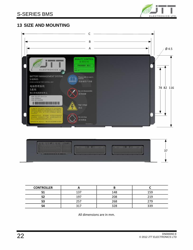
13 SIZE AND MOUNTING
A
B
C
78 82 116
Ø 4.5
37
CONTROLLER A B C
S1 137 148 159
S2 197 208 219
S3 257 268 279
S4 317 328 339
All dimensions are in mm.

S-SERIES BMS
23
DN000092.E © 2012 JTT ELECTRONICS LTD
14 BMS Link – Monitor and Diagnose Your Battery Pack
Monitor and Diagnose problems in the Battery Pack from your PC or Laptop in real time.
BMS Link is compatible with all JTT BMS products
The most comprehensive, battery integrated monitoring, logging and control software
Windows (XP, 7)
Multi-page layout for displaying battery data in numerical and graphical form.
Cell voltages, temperatures, SOC, SOH, cell DCRs, balancing status, alarm status, battery voltage, battery current, and more available in real time.
Service Mode available for additional data, and forcing all battery components such as fans, heaters, relays, cell balancing on and off.
Controller identification by serial number and firmware version.
Cell identification and tracking by serial number and cell lifetime data for warranty and troubleshooting.
Record, save, and analyze data log files
Updates with all cell and battery pack information every 100ms
Alarm status information for all controllers within the battery

S-SERIES BMS
24
DN000092.E © 2012 JTT ELECTRONICS LTD
15 TYPICAL WIRING
POWER
Following diagram shows the wiring for the supply power and ground for S-Series controllers.
A-11
A-22V supply
GND
COMMUNICATION
S-Series controllers are optionally equipped with isolated CAN bus and/or isolated RS-232 for external communication.
The RS-232 port can be used for communication with a charger, digital screen, dashboard, data
logger etc. In addition there is a diagnostic CAN bus interface for controller firmware loading and battery pack monitoring.
The following diagram is communication wiring for the S-Series controllers.
Iso. CAN H
Iso. CAN L
Diag CAN H
Diag CAN L
A-21
A-20
A-19
A-18
Iso. RS232 GND
Iso. RS232 RX
Iso. RS232 TX
A-15
A-16
A-17
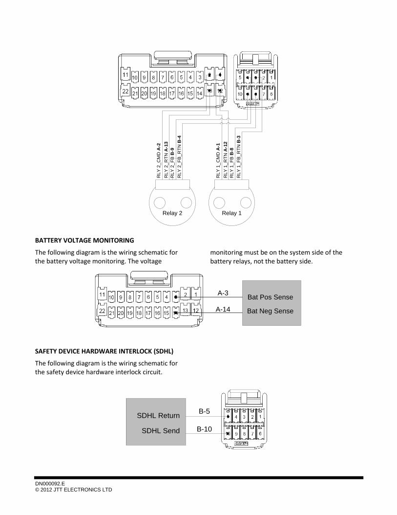
RELAYS
The following diagram is the wiring schematic for two battery relays with optional position feedback.
DN000092.E © 2012 JTT ELECTRONICS LTD
Relay 1Relay 2
RL
Y 2
_C
MD
A-2
RL
Y 2
_R
TN
A-1
3
RL
Y 2
_F
B B
-9
RL
Y 2
_F
B_
RT
N B
-4
RL
Y 1
_C
MD
A-1
RL
Y 1
_R
TN
A-1
2
RL
Y 1
_F
B B
-8
RL
Y 1
_F
B_
RT
N B
-3
BATTERY VOLTAGE MONITORING
The following diagram is the wiring schematic for the battery voltage monitoring. The voltage
monitoring must be on the system side of the battery relays, not the battery side.
A-3
A-14
Bat Pos Sense
Bat Neg Sense
SAFETY DEVICE HARDWARE INTERLOCK (SDHL)
The following diagram is the wiring schematic for the safety device hardware interlock circuit.
B-5
B-10
SDHL Return
SDHL Send
S-SERIES BMS
26
DN000092.E © 2012 JTT ELECTRONICS LTD
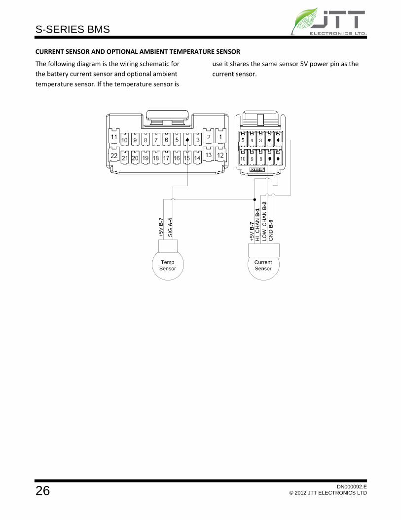
CURRENT SENSOR AND OPTIONAL AMBIENT TEMPERATURE SENSOR
The following diagram is the wiring schematic for
the battery current sensor and optional ambient
temperature sensor. If the temperature sensor is
use it shares the same sensor 5V power pin as the
current sensor.
+5
V B
-7H
I_C
HA
N B
-1
LO
W_
CH
AN
B-2
GN
D B
-6
Current
Sensor
Temp
Sensor
+5
V B
-7
SIG
A-4