sae nis effi cycle 2014
TRANSCRIPT

SAE NIS EFFI-CYCLE 2014
DESIGN REPORT
Team ID : 14036
Team Name : ThunderBolt 2.0
College Name : National Institute of Technology
City : Warangal, Andhra Pradesh
Team Captain : Rohit Chowdhury
Report Author : Srivatsa Yeluripati
Report Co-Author : Hardik Jain
1. ABSTRACT:
The main objective of Effi-cycle 2014 is to promote
innovation and generate consciousness amongst the
young engineers towards environment friendly mobility
solution. Keeping this in mind, team Thunderbolt2.0 has
made sincere efforts to design and fabricate an energy
efficient human cum-battery powered two-seater trike
which is safe, economical in design and delivers high
performance promoting ‘greenovation’. This report
contains an overview of the design work for each of the
involved subsystems.
Team targets are listed as follows:
Providing flexible and independent power
transmission to integrate various powers.
Comfortable manoeuvring: low centre of
gravity, smooth steering, electronics
systems.
Swift trike with considerable acceleration,
braking and targeted velocity of 35 mph.
Ensuring ergonomics and safety with
features like Smart Charger and IEA.
Economical design that can be modified for
mass production for commercial purpose.
Special features of the trike include ignition locking
system, impact energy absorber, foot straps for pedals,
lock levers of brakes, brake accumulator, smart charging
systems, load sensing systems etc. The ten member team
Thunderbolt 2.0 of National Institute of Technology,
Warangal consisted of engineering students from various
backgrounds. Drawing upon multidisciplinary
engineering knowledge, the team members were divided
into various departments: Designing, Finite Element
Analysis, Steering, Transmission, Braking, Suspension
and Electrical Systems.
Fabrication is under process and the entire team is
excited to complete a successful Effi-cycle.
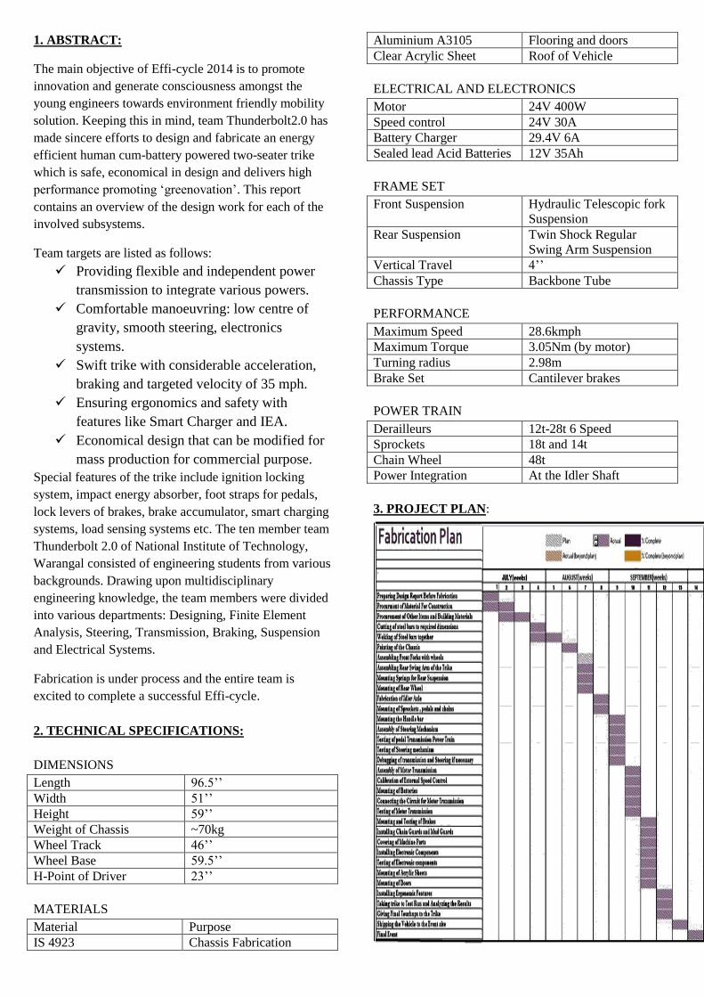
2. TECHNICAL SPECIFICATIONS:
DIMENSIONS
Length 96.5’’
Width 51’’
Height 59’’
Weight of Chassis ~70kg
Wheel Track 46’’
Wheel Base 59.5’’
H-Point of Driver 23’’
MATERIALS
Material Purpose
IS 4923 Chassis Fabrication
Aluminium A3105 Flooring and doors
Clear Acrylic Sheet Roof of Vehicle
ELECTRICAL AND ELECTRONICS
Motor 24V 400W
Speed control 24V 30A
Battery Charger 29.4V 6A
Sealed lead Acid Batteries 12V 35Ah
FRAME SET
Front Suspension Hydraulic Telescopic fork
Suspension
Rear Suspension Twin Shock Regular
Swing Arm Suspension
Vertical Travel 4’’
Chassis Type Backbone Tube
PERFORMANCE
Maximum Speed 28.6kmph
Maximum Torque 3.05Nm (by motor)
Turning radius 2.98m
Brake Set Cantilever brakes
POWER TRAIN
Derailleurs 12t-28t 6 Speed
Sprockets 18t and 14t
Chain Wheel 48t
Power Integration At the Idler Shaft
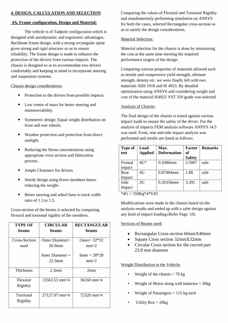
3. PROJECT PLAN:
4. DESIGN, CALCULATION AND SELECTION
4A. Frame configuration, Design and Material:
The vehicle is of Tadpole configuration which is
designed with aerodynamic and ergonomic advantages.
Backbone frame design, with a strong rectangular spine
gives strong and rigid structure so as to ensure
reliability. The frame design is made to enhance the
protection of the drivers from various impacts. The
chassis is designed so as to accommodate two drivers
comfortably and keeping in mind to incorporate steering
and suspension systems.
Chassis design considerations:
Protection to the drivers from possible impacts.
Low centre of mass for better steering and
manoeuvrability.
Symmetric design: Equal weight distribution on
front and rear wheels.
Weather protection and protection from direct
sunlight.
Reducing the Stress concentrations using
appropriate cross section and fabrication
process.
Ample Clearance for drivers.
Sturdy design using fewer members hence
reducing the weight.
Better steering and wheel base to track width
ratio of 1.3 to 1.5.
Cross-section of the beams is selected by comparing
flexural and torsional rigidity of the members.
TYPE OF
beams
CIRCULAR
beams
RECTANGULAR
beams
Cross-Section
used
Outer Diameter=
26.9mm
Inner Diameter =
22.3mm
Outer= 32*32
mm^2
Inner = 28*28
mm^2
Thickness 2.3mm 2mm
Flexural
Rigidity
13563.53 mm^4 36160 mm^4
Torsional
Rigidity
27127.07 mm^4 72320 mm^4
Comparing the values of Flexural and Torsional Rigidity
and simultaneously performing simulation on ANSYS
for both the cases, selected Rectangular cross-section so
as to satisfy the design considerations.
Material Selection:
Material selection for the chassis is done by minimising
the cost at the same time meeting the required
performance targets of the design.
Comparing various properties of materials allowed such
as tensile and compressive yield strength, ultimate
strength, density etc. we were finally left with two
materials AISI 1018 and IS 4923. By detailed
optimization using ANSYS and considering weight and
cost of the material IS4923 YST 310 grade was selected.
Analysis of Chassis:
The final design of the chassis is tested against various
impact loads to ensure the safety of the driver. For the
analysis of impacts FEM analysis software ANSYS 14.5
was used. Front, rear and side impact analysis was
performed and results are listed as follows:
Type of
test
Load
Applied
Max.
Deformation
Factor
of
Safety
Remarks
Frontal
impact
4G* 0.4386mm 2.5067 safe
Rear
Impact
4G 0.87484mm 1.88 safe
Side
Impact
2G 0.20356mm 3.391 safe
*4G = 350Kg*4*9.81
Modifications were made in the chassis based on the
analysis results and ended up with a safer design against
any kind of impact loading.(Refer Page: 10)
Sections of Beams used:
Rectangular Cross section 60mmX40mm
Square Cross section 32mmX32mm
Circular Cross section for the curved part
23.9 mm diameter
Weight Distribution in the Vehicle:
• Weight of the chassis = 70 kg
• Weight of Motor along with batteries = 30kg
• Weight of Passengers = 115 kg each
• Utility Box = 20kg

• Total weight = 350kg
Location of Centre of Gravity: (Refer Page: 10)
Distance from Front axle = 787.6mm
Height from the ground = 635mm
4B. Drive Train:
Transmission drive trains designed are independent for
Human and Motor powered transmissions. It is achieved
by using both the sides of the wheel through dual
mounting wheel hub. (Refer Page: 10,11)
Human Powered Drive Train:
Human Powered drive train consists of a parallel
transmission of both drivers combined at the
idler shaft before transmitting it to the main
driven wheel.
The power of the both the drivers add up when
at the idler shaft if they drive at same speed.
Motor powered Drive Train:
The Motor drive train consists of a 400W BLDC
electric motor mounted with gearbox of
reduction ratio of 10.
The motor is controlled using a 24V, 30A speed
controller and is driven by two 12V batteries
connected in series with a total discharge of
35Amp.hr.
Motor drive train is installed with two
derailleurs so as to provide large range of
torques and speeds.
TABLE 1: Motor and Battery Specifications
BLDC Motor
1. Power 400W
2. Voltage 24V
3. Rated Rpm 1500Rpm
4. Rated Torque 2.5 N.m
5. Weight 11Kg
Battery
1. Type Sealed Lead-acid
2. Make Amaron
3. Output voltage 12V
4. Maximum
Discharge
35Amp.hr
5. Weight 10Kg
Why BLDC Motor?
Less maintenance due to absence of brushes.
High efficiency, no voltage drop across the
brushes.
Reduced size due to superior thermal
characteristics.
Higher speed range- no mechanical limitation
imposed by brushes or commutator.
Brushless motor offers higher reliability, less
noise and longer lifetime.
Disadvantages of BLDC Motor:
High cost of construction.
Requires control strategies which are both
complex and expensive.
Controller Specifications:
Input : 24VDC
Direction reversible on external contact
Dynamic brake on request
Factory set current limit of 25A
Over Temperature cut-off
Factory set soft starter
Over voltage and under voltage cut-off.
Independent Transmission and Torque Availability:
Trike is designed so that it can be driven by both
the drivers and also electric motor. The Motor and
Human powered transmission are made independent to
prevent the problems in case of failure of one of the
drive trains. (Refer Page: 10,11)
The Motor drive train is equipped with two
derailleurs providing us about 36 different speed and
torque ranges. We used the concept of varying reduction
ratios using derailleurs so as to obtain high torque of
about 125 N.m and also higher speed of nearly 29Kmph.
TABLE 2: Power Train Specifications
Power Train Specification Value
Maximum Torque Requirement(On Slope
of 5deg)
141.28N.m
Minimum Torque Requirement 14.54N.m
Maximum torque given by Motor 3.05N.m
Battery Run Time at Rated RPM 1.67 hrs.

Battery Run Time at Critical Torque
Requirement
0.9 hrs.
Reduction Ratio Obtained 7.34 to 40
Average Speed in low Torque conditions 28.6kmph
Average speed in Maximum torque
conditions
4.75kmph
Maximum Obtained Human Power* 282 W
Sustainable Power from one Driver* 137W
Average Torque Obtained by Human
Power
14.46N.m
*Source: Bicycling Science (3rd Edition) by David
Gordon Wilson
Because of the derailleurs used in the motor drive train
we obtain wide range of reduction ratios of the RPM
from the motor. The motor is initially stepped down by a
ratio of 10 with the help of a Gearbox. Different
reduction ratios obtained are shown in the table given
below:
TABLE 3: Some of the Reduction ratios of RPM
obtained in the motor drive train
Red
uct
ion A
t th
e
Gea
r box
spro
cket
mounte
d
spro
cket
s on
der
aill
eur
Red
uct
ion p
rovid
ed sprock
et
mount
ed
paralle
l to
deraill
eur
Spro
cket
s on
der
aill
eur
Red
uct
ion p
rovid
ed
Tota
l R
educt
ion
on
th
e
mo
tor
on
rea
r
wh
eel
10 14 12 /1.16 14 12 /1.16 7.34
14 x1
14 x1 10
16 x1.14
16 x1.14 13.0
18 x1.28
18 x1.28 16.5
20 x1.42
20 x1.42 20.3
22 x1.57
22 x1.57 24.6
24 x1.71
24 x1.71 29.3
28 x2
28 x2 40
Finally a maximum reduction of 40 and minimum
reduction of 7.34 is obtained in the speed was obtained.
Torque Calculations:
To choose a motor(s) capable of producing enough
torque to propel the vehicle, it is necessary to determine
the total effort (TE) requirement for the vehicle.
While calculating the minimum torque requirement of
the vehicle various considerations are required based on
the context. Two cases were considered: one is cruising
condition on flat road and other is moving on a gradient.
For torque calculations we consider the theoretical
weight of the vehicle to be 350Kg along with drivers.
Hence Gross Weight of the Vehicle = 350*9.81 =
3433.5N
1. Effort required to overcome rolling Friction:
Rolling Resistance (RR) is the force necessary
to propel a vehicle over a particular surface.
Force required to overcome rolling
friction = GVW*Friction coefficient
Friction Coefficient = 0.01
Hence total effort required = 34.335N
2. Effort against the gradient:
This calculation is made using the maximum
angle or grade the vehicle will be expected to
climb in normal operation.
In Gradient test there is a Force of
Mgsin (α) Acting on the vehicle:
Inclination
Effort against
Gradient
3 degrees 179.69N
4 degrees 239.5088N
5 degrees 299.249N
Combining both the above cases total torque required is
calculated
Torque = (Total Effort * Radius of Wheel *
Resistance Factor)
85% efficiency of the drive trains (resistance factor =
1.15) was considered
Minimum torque requirement on flat road:
Total
Effort(N)
Torque
Required(min)26''
wheel
Torque
Required(min)29''
wheel
34.335 12.83Nm 14.45Nm
Minimum torque requirement on gradient:
Incl
inat
ion
Effort
against
Gradient(
N)
Total
Effort
(N)
Torque
Required(mi
n)26'' wheel
Torque
Required(mi
n)29'' wheel
3
deg
rees 179.69N
214.0
25
79.9918437
5
90.6492186
3
4
deg
239.5088
N
273.8
438
102.349120
3
115.985172
3

rees
5
deg
rees 299.249N
333.5
75
124.673656
3
141.284023
4
Finally it is necessary to check whether the wheel can
transmit the required torque or not. So we calculated the
maximum tractive torque of the drive wheel for the
reality check.
* 50-50 weight distribution was considered in the
vehicle in front and rear.
Max Torque That can be transmitted = (%wt. on driving
wheel)*g*(friction factor of floor)*radius of wheel
*We took floor to be concrete with friction factor 0.4
Hence Maximum torque that can be transmitted came up
to be 252.7Nm which is more than our maximum torque
requirement.
4C.1) Suspension: (Refer Page: 11)
Suspension system in the trike is designed in order to
have a smooth and comfort drive. For front suspension,
telescopic fork suspensions (Figure 1) are used and for
the rear suspension Twin shock regular swing arm
(Figure 1) was installed. The Twin shock swing arm
suspension has a vertical travel of 4inches so as to keep
the motor and chassis shock free and intact.
TABLE 4: Specifications
Natural eye to eye length of spring 16.7cm
Natural length of actual spring 9.5cm
Stiffness constant of Springs used 210.66kN/m
Maximum Compression Available 5.8cm
In twin shock swing arm, two springs are used in
parallel. Hence effective spring constant is 421.33kN/m
To obtain the vertical travel without any intersection
with the body of the vehicle, the length of the swing arm
(Lswingarm) is taken as 20 inches (0.508m).
Calculations:
At static conditions sag is assumed to be 20% and hence
the force on the springs is given by F
F=K*x, where
F is the force exerted by the eq. spring
X is the initial compression due to load of
drivers and chassis
F=421.33*1000*(20% of 0.058)
F=421.33*1000*0.0116
F=4.888 KN
Since the system is at rest (equilibrium), net moment
about pivot is zero
F*L - Fr*Lswingarm + W*Lw= 0
Where,
Fr is the reaction force on rear wheel =2060 N
W is weight of the swing arm = approx. 50 N
Lw is the distance of C.O.G of swing arm from
pivot= approx. 20cm
L = (Fr* Lswingarm – w*Lw)/F
L= 21.4 cm
Hence, the spring force must act at a distance of 21.2 cm
from the pivot.
Under Max Torque 140 Nm from motor, at constant
velocity:
L*F = Fr*Lswingarm + Fc*Cos (T)*Rspr – Fc*Sin
(T)*Lswingarm – Ftr*Rw – W*Lw
Where, Fc is the tension in chain, such that
Fc*Rspr= 140, i.e. Fc = 2413.7 N
Rw is the radius of wheel = 14.5 inches = 36.83
cm
T is the angle between Fc and horizontal=2.64
degree
Rspr is the radius of largest sprocket= 5.8 cm
Ftr is traction force. Since trike is in constant
velocity, net moment about cogwheel is 0.
Hence Ftr*Rw=Fc*Rspr i.e. Ftr= 380.125 N F = 4.568 KN
Now, F = K*x

X = 1.08 cm this is the net compression under
max torque conditions.
Similarly, under Minimum torque 15 Nm, at constant
velocity:
T=0.17degrees Rspr =2.48 cm
L*F = Fr*Lswingarm + Fc*Cos (T)*Rspr + Fc*Sin
(T)*Lswingarm – Ftr*Rw – W*Lw
F = 4985.34 KN
Therefore compression is spring
X = F/K = 1.2 cm
Hence, for l = 21.4 cm, a compression of less than 1.2
cm is maintained, both at rest and uniform velocities.
Hence max compression available after sag = 5.8 –
1.2 = 4.6 cm
Now to obtain a vertical travel of 4 inches, the swing
arm rotates an angle of about 11o
Assuming the travel of the spring to be almost linear, the
spring is positioned at an angle of about 61.55o
4C.2) Braking System:
The trike used cantilever shoe brakes on all wheels
which can be locked simultaneously as desired. The
front two cantilevers are controlled by a double barrel
lever which can lock both the front wheels
simultaneously to prevent any skidding or slip. This also
prevents the toppling of the trike.(Refer Page: 11)
Reason for Cantilever Brakes:
Over disc brakes-
Disc brakes are heavy compared to rim brakes.
It involves a complex mechanism involving
hydraulics
Lighter disc brakes are expensive
Over calliper brakes-
It has high stiffness factor. Thus high braking
power needed for the weight of the trike
Weight Transfer during braking:
Where,
f1, f2 are friction coefficients on front and rear wheels.
N1 and N2 are normal reactions on the wheels.
X+Y = B = Wheel Base
2N2+N1 = 350g = 3433.5
Calculating moments about contact point of the rear
wheel,
2N2 (B) = W(X) + m (f1g)*h, where f1 = f2 = 0.6
2N2 (1498.6) = 3433.5*711 + 350*0.6*9.81*635
Hence N2 = 1250.961N and N1 = 931.576N
%weight on front wheels = 72%
%weight on rear wheel = 28%
4C.3) Steering :( Refer Page: 12)
The steering geometry of our trike is basically an
Ackerman mechanism, which is driven by a Single Tie
Rod and Drag Link arrangement.
Calculation of the links of Ackerman:
According to our design,
Wheel track, w = 46 inches = 116.84cm
Wheel base, l = 59.5 inches = 151.13 cm
Link length d is set to a comfortable value.
Representation of Ackerman Links
Using the formula,
Eq 1.
A graph is plot between i vs (Blue Curveis plotted
for different values of β.
Using Ackerman perfect Steering condition,

i.e., cot δ - cotδi = 0.773……... Eq.2
Perfect steering curve (RED Curve) is plotted using Eq2.
The curves plotted using the Eq1 are compared to that of
Eq2 so as to obtain the values of β for which the curves
almost coincide for large range of angles.
The process is repeated for different values of d and
corresponding value of β is obtained.
d (in inches) Negligible error up to i =
7 21 degrees along the curve 30
8 19 degrees along the curve = 30
9 16 degrees along the curve = 30
10 13 degrees along the curve = 30
11 20 degrees along the curve = 28
12 19 degrees along the curve = 28
13 15 degrees along the curve = 28
14 11 degrees along the curve = 28
15 19 degrees along the curve = 26
16 18 degrees along the curve = 26
17 14 degrees along the curve = 26 The highlighted data represents the values of link length
d and for which there is negligible error between the
two curves up to large values of i.
The value of d is comfortably chosen as 12 inches.
Now, the lengths of the Ackerman are given by
LAB = 116.84 cm = 46 inches
LBC = 30.48 cm = 12 inches
LCD = 88.22 cm = 34.7 inches
LAD = 30.48 cm = 12 inches
To obtain Perfect steering Conditions we solve Eq1 and
Eq2 simultaneously.
i = 17.01 degrees
= 13.90 degrees
At these perfect Steering Conditions are satisfied
Radius of curvature at these angles is 5.57m
Calculation of Turning Radius: (Refer Page: 12)
To calculate the turning radius, the outer radius of the
vehicle during turning was assumed to be 3.8m (As we
require 4m of outer radius to pass the manoeuvrability
test).
Therefore, outer steering angle,
= Sin-1
(l/Ro)
= Sin-1
(151.13/380)
= 23.44 degrees
Inner steering angle is obtained by solving Eq1.
i = 39.95 degrees
Turning radius can be calculated as
R= Sqrt[ (Ro*Cos() – (w/2))^2 + a^2 ]
R = Sqrt[ (380cos(23.44) – (116.84/2))^2 + (71.1)^2 ]
Hence, Turning Radius, R = 2.98 m
Calculation of lengths of Driving links and turning
angles:
Other required link lengths are calculated with the help
of sketcher in SOLIDWORKS.
Hence LEF = 13.5cm and LGF = 63.2cm
When the vehicle takes sharp right turn, the steer of
handle bar is calculated to be,
R =52.33 degrees When the vehicle takes sharp left turn, the steer of
the handle bar is calculated to be,
L =59.5 degrees Calculation of Critical Speed:
Critical speed gives the maximum speed at which the
vehicle can take a turn for a given turning radius. It is
calculated as follow,
Critical speed, S = sqrt(u*R*g),
Where,
μ = 0.6 is the coefficient of friction between the tyre
and the ground
R is the radius at which the vehicle turns
g is acceleration due to gravity = 9.81 m/s2
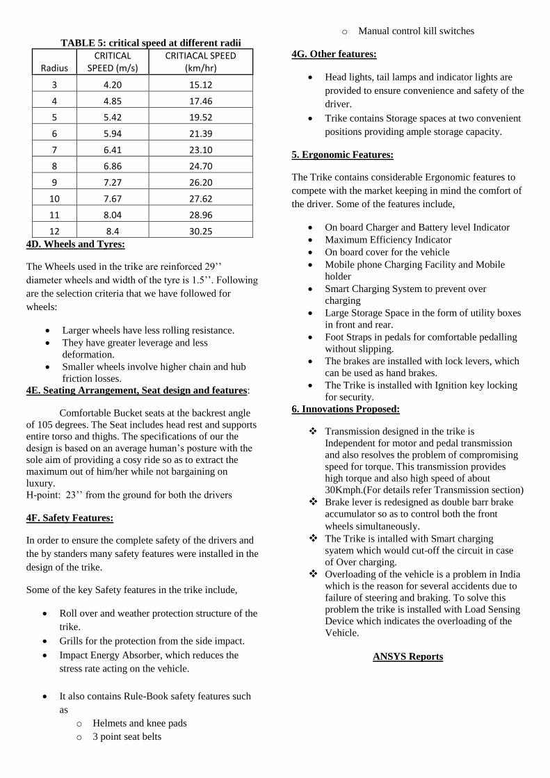
TABLE 5: critical speed at different radii
Radius CRITICAL
SPEED (m/s) CRITIACAL SPEED
(km/hr)
3 4.20 15.12
4 4.85 17.46
5 5.42 19.52
6 5.94 21.39
7 6.41 23.10
8 6.86 24.70
9 7.27 26.20
10 7.67 27.62
11 8.04 28.96
12 8.4 30.25
4D. Wheels and Tyres:
The Wheels used in the trike are reinforced 29’’
diameter wheels and width of the tyre is 1.5’’. Following
are the selection criteria that we have followed for
wheels:
Larger wheels have less rolling resistance.
They have greater leverage and less
deformation.
Smaller wheels involve higher chain and hub
friction losses.
4E. Seating Arrangement, Seat design and features:
Comfortable Bucket seats at the backrest angle
of 105 degrees. The Seat includes head rest and supports
entire torso and thighs. The specifications of our the
design is based on an average human’s posture with the
sole aim of providing a cosy ride so as to extract the
maximum out of him/her while not bargaining on
luxury.
H-point: 23’’ from the ground for both the drivers
4F. Safety Features:
In order to ensure the complete safety of the drivers and
the by standers many safety features were installed in the
design of the trike.
Some of the key Safety features in the trike include,
Roll over and weather protection structure of the
trike.
Grills for the protection from the side impact.
Impact Energy Absorber, which reduces the
stress rate acting on the vehicle.
It also contains Rule-Book safety features such
as
o Helmets and knee pads
o 3 point seat belts
o Manual control kill switches
4G. Other features:
Head lights, tail lamps and indicator lights are
provided to ensure convenience and safety of the
driver.
Trike contains Storage spaces at two convenient
positions providing ample storage capacity.
5. Ergonomic Features:
The Trike contains considerable Ergonomic features to
compete with the market keeping in mind the comfort of
the driver. Some of the features include,
On board Charger and Battery level Indicator
Maximum Efficiency Indicator
On board cover for the vehicle
Mobile phone Charging Facility and Mobile
holder
Smart Charging System to prevent over
charging
Large Storage Space in the form of utility boxes
in front and rear.
Foot Straps in pedals for comfortable pedalling
without slipping.
The brakes are installed with lock levers, which
can be used as hand brakes.
The Trike is installed with Ignition key locking
for security.
6. Innovations Proposed:
Transmission designed in the trike is
Independent for motor and pedal transmission
and also resolves the problem of compromising
speed for torque. This transmission provides
high torque and also high speed of about
30Kmph.(For details refer Transmission section)
Brake lever is redesigned as double barr brake
accumulator so as to control both the front
wheels simultaneously. The Trike is intalled with Smart charging
syatem which would cut-off the circuit in case
of Over charging. Overloading of the vehicle is a problem in India
which is the reason for several accidents due to
failure of steering and braking. To solve this
problem the trike is installed with Load Sensing
Device which indicates the overloading of the
Vehicle.
ANSYS Reports

Frontal Impact [4G]
Side Impact [2G]
Rear Impact [4G]
Different Views of Chaasis
Schematic Representation of COG
TRANSMISSION
Layout of Motor Driven Power Train

Layout of Human Powered Driven Train
OverView of Transmission
Load Analysis Chart of 24V, 400W BLDC Motor
SUSPENSION
Figure 1 Figure 2
BRAKING SYSTEM
Double Barrel Brake Accumulator
Cantilever Brakes

STEERING
Single Tie Rod Drag Link Mechanism
Calculation of Turning Angles
Graph Showing the curves obtained from equations 1
and 2
ELECTRIC CIRCUIT DIAGRAMS
Block Diagram of Load Sensing Device
Smart Charging System
Circuit Diagram in the Vehicle
Impact Energy Absorber
OUR SPONSERS: