safety and availability evaluation of railway operation...
TRANSCRIPT

Safety and availability evaluation of railway operation based on the state of signalling systems
Amparo Morant1, Anna Gustafson2, Peter Söderholm3,4, Per-Olof Larsson-Kråik1,4, Uday Kumar1
1 Operation and Maintenance Engineering, Luleå University of Technology, Sweden
2 Mining and Geotechnical Engineering, Luleå University of Technology, Sweden
3 Quality Technology and Management, Luleå University of Technology, Sweden
4 Trafikverket (the Swedish Transport Administration), Sweden
Corresponding author: [email protected], +46 722 44 6769
Abstract
A framework is presented to evaluate the safety and availability of the railway operation, and quantifying
the probability of the signalling system not to supervise the railway traffic. Since a failure of the signalling
systems still allows operation of the railway, it is not sufficient to study their effect on the railway
operation by considering only the failures and delays. The safety and availability are evaluated, handling
both repairs and replacements by using a Markov model. The model is verified with a case study of
Swedish railway signalling systems with different scenarios. The results show that the probability of being
in a state where operation is possible in a degraded mode is greater than the probability of not being
operative at all, which reduces delays but requires other risk mitigation measures to ensure safe operation.
The effects that different improvements can have on the safety and availability of the railway operation
are simulated. The results show that combining maintenance improvements to reduce the failure rate and
increase the repair rate is more efficient at increasing the probability of being in an operative state and
reducing the probability of operating in a degraded state.
Keywords: Railway; signalling systems; operation; maintenance; availability; reliability; safety; Markov;
dependability; RAMS
1. Introduction
The railway signalling system protects, controls and supervises the railway traffic, in order to ensure safe
operation. The signalling system supervises the railway at all times, not only when a train passes, which
makes it a continuously operating system. Hence, all maintenance time will affect the operation of the
signalling system.
Signalling systems are an example of large complex systems made of multiple hierarchical layers and
indenture levels [1], and with a long expected useful life (in general, between 30 and 40 years). The
performance evaluation of complex systems has its own challenges, i.e. the lack of the system overview
and the conflicting objectives or unclear distribution of responsibilities between the actors involved (e.g.
the manufacturer, operator, maintainer, etc.) [1].
The long useful life of the system implicates that the process and procedures to record the failures could
be modified during the time, showing inconsistencies or having incomplete data [2-3]. It can also be
affected on changes of the provider of the components; design updates; changes of maintenance
procedures, etc. Furthermore, data sets are collected for maintenance management rather than reliability
engineers; hence they may lack vital information for a proper reliability evaluation, which can lead to
wrong or incomplete conclusions [2]. The standard EN 50126 [4] defines the terms of reliability,
availability, maintainability and safety (RAMS) as:

Reliability is the probability that an item can perform a required function under given conditions
for a given time interval.
Availability is the ability of a product to be in a state to perform a required function under given
conditions at a given instant of time or over a given time interval assuming that the required
external resources are provided.
Maintainability is the probability that a given active maintenance action, for an item under given
conditions of use, can be carried out within a stated time interval when the maintenance is
performed under stated conditions and using stated procedures and resources.
Safety is the freedom from an unacceptable risk of harm.
The RAMS of a railway system is influenced in three ways: by sources of failure introduced internally
within the system at any phase of the system lifecycle (system conditions), by external sources of failure
on the system during operation (operating conditions) and by external sources of failure on the system
during maintenance activities (maintenance conditions) [4]. These sources of failure can interact, and can
affect greatly the operating performance of the railway systems, explaining the large discrepancies
observed between intrinsic and effective reliability of existing systems [1-4].
To operate on a specific railway corridor, the signalling systems of train and infrastructure must be
interoperable. In Sweden, state companies such Transitio or Rikstrafiken (via ASJ) provide the operators
with the necessary rolling stock to solve this problem when necessary [5]. The main purpose of the railway
signalling systems (which is, to ensure the safe operation of the railway) is fulfilled by the combination
of the functionalities of all its parts, even though each part has its own particular goal and can be
considered a complex system on its own.
When analysing the performance of a railway signalling system, to analyse the different parts
independently would not give a full picture of the global performance, since the final purpose (to ensure
the safe railway operation) depends on the relationship between them. Therefore, the railway signalling
system can be considered as a system of systems (SoS) [6], and the interoperability between the different
systems needs to be assured. Furthermore, the complex architecture of electronics and the
interdependency between the components and systems make it difficult to identify and analyse anomalous
behaviours [7]. In the case of signalling systems, this difficulty may be illustrated by the high number of
no fault found events or not defined failures that are recorded [8].
The functionality of a railway signalling system is based on the principle of “fail safe”; this means the
railway section where a failure is located will not be fully operative, until the failure is repaired, to ensure
safety [4]. Figure 1 describes the state transition diagram, showing an overview of the main states of the
signalling system [9]. Since a failure of the signalling system still allows operation of the railway, albeit
limited, it is not sufficient to study its effect on the railway operation in terms of reliability and safety by
considering only the failures and delays [10]. Furthermore, the probability of being operative in a
degraded mode is not easily measurable, since it is not directly linked to the number of failures and the
delays.

Figure 1: Example of state transition diagram (adapted from [9]]
A failure in a signalling system has economic consequences (penalties, high amount of maintenance
resources, etc.), can affect the operation (delays, cancellations, speed restrictions, etc.), and have safety
consequences. With a failed signalling system, a driver will operate in a degraded mode, with safety
assured by other mitigation measures, such as low speed restrictions. The possibility of operating in a
degraded mode reduces the economic and operational effects of a failure of the signalling systems, but
makes it more difficult to evaluate the railway operation, since a failure will not necessarily be visible
when considering the delays or cancelations, even though safety has been compromised. Within the
maintenance area, the train records of the on-board part of the signalling system can help to identify a
failure since they contain the information received from the infrastructure’s part of the signalling system.
Different approaches can be used to evaluate the safety and availability of railway signalling systems. As
stated by Restel [10], the classification into the subsets of availability and failure is not sufficient to model
the reliability and safety of the railway system. There is a need for evaluating the safety and availability
of the railway operation, and to quantify the probability of the signalling system not to supervise the
railway traffic. This paper fulfils this need, by presenting a framework to evaluate the safety and
availability of railway operation, focusing on the effects of railway signalling systems. Previous
contributions focused on the evaluation of a particular subsystem [11-17]. In contrast, this paper evaluates
the whole signalling SoS. This is a good approach to use when it is not possible to determine the failed
system or the specific failure mode. This paper is based on records from corrective maintenance showing
the variance found in real data; which supports a check of the validity of the model for future
implementation in industry. The safety and availability are evaluated during the maintenance and
operation phases of the life cycle, handling both repairs and replacements of the different systems of the
various subsystems of the SoS. The knowledge gained will facilitate the decision-making process when
improving or updating the railway infrastructure.
This paper is structured as follows. Section 2 introduces the Swedish railway signalling. Section 3 presents
the developed methodology for safety and availability evaluation of the railway operation. Section 4
presents the analysed scenarios and summarizes the results obtained. Finally, the paper concludes with a
discussion of the results and the conclusions in Sections 5 and 6.

2. Case study: the Swedish railway signalling SoS
The research is based on data obtained from the Swedish infrastructure manager (Trafikverket) for a fully
operative railway corridor where the ATC (automatic train control) signalling system supervises and
controls the network. The Swedish signalling SoS is composed of the following subsystems [18]:
Traffic management system (TMS): creates an interface between the traffic operator and the
railway network.
Signals: give or restrict permission to the train on coming into a track section.
Interlockings (IXL) / Radio block centre (RBC): receive the input from the different systems
(e.g. track circuits, level crossings, signals, TMS), and calculate and return as an output the train
operation restrictions to ensure safe traffic operation.
Track circuits: are responsible for the train location.
Balise group (BG): give input from the track to the onboard signalling system (e.g. speed limits,
driving mode, etc.).
Level crossings (LC): coordinate the road traffic crossing the railroad.
Signalling boards (SB): give the train fixed information (e.g. on tunnels, bridges, speed
restriction areas, etc.).
It is possible to find other signalling systems (e.g. axle counters, automatic warning system, radio loop,
etc.). However, these are not considered in this paper since they are not part of the Swedish signalling
SoS and there is no corrective maintenance data for them. However, it would be possible to include them
in the evaluation by making minor modifications in the model. A more accurate and complete description
of the different signalling systems can be found in [19].
In order to guarantee safe operation, the railway signalling divides the railway corridor into track sections
(or blocks) where only one train is allowed at a given time [13]. A track section is supervised by an
interlocking located at the end of that section, usually at a station. Signals are placed at the entrance of
every section and sometimes in the middle to allow or restrict the passing of a train into that section.
Signals restrict the passing of a train when a failure occurs on a track circuit or an interlocking, and warns
it to circulate with caution when there is a failure in a level crossing. When a signal fails, the balise group
associated with it will force the train to stop. If a balise does not work properly, it will produce an
emergency brake (EB). A single TMS controls the railway traffic of various corridors simultaneously. If
the TMS fails, the operation has an automatic mode that allows normal operation for a maximum of two
hours. After that time, operation is not possible. If there is a stoppage of operation caused by a failure in
the signalling system of a track section, railway operation can still be possible on that section if the
dispatcher allows the driver to circulate with caution in a degraded operational mode. In this case, the
maximum speed is 40 km/h and the driver’s visual supervision is required to ensure safe circulation (e.g.
there is no damage in the track; the switch is in the correct position etc.). Summarizing, from a reliability
point of view, all the subsystems conforming the signalling SoS work in series to fulfil the main purpose
of ensuring a safe railway operation. Since this paper focus on the performance of the signalling SoS
regarding the railway operation, it only consider those failure which will affect the performance (e.g.
failures that occurs in a system that is redundant and thereby continuous to fulfil its purpose are not
considered).
2.1. Data collection
Corrective maintenance work orders related to the railway infrastructure in Sweden are managed in a
failure recording system called “0felia”, while the data about the architecture of the whole railway

infrastructure is managed by an asset register system (BIS). Both these databases were used as input for
this paper.
The process of failure reporting is described in a document of the Swedish infrastructure manager [20].
The document lists the different steps and explains how to proceed from the time a failure is identified
and reported until the corrective action is finished and the work order (WO) related to the failure is closed.
Many actors are involved in the process, since the train operator can identify the failure, the railway
infrastructure manager controls the activity performed on the railway network and a subcontracted
company performs the corrective maintenance action. Since some parameters in 0felia are registered
manually, processing the data is necessary to group information in an appropriate manner.
The corrective maintenance data covers WOs from January 2003 until November 2012 on a 203 km long
railway corridor, divided into 50 track sections and located in the northern part of Sweden. Specifically,
9,030 WOs were registered during that period, of which 2,455 were associated with signalling systems.
No changes of configuration were made during the years included in the maintenance data used for this
research on the railway corridor considered. Hence, it can be assumed the WOs represent maintenance,
not design changes or updates.
The data were processed to eliminate inconsistent or poor-quality records. When studying the time to
restore in the WOs, it was found that, of the 2,456 WOs related to failures of signalling systems, 103 WOs
had a restoration time of zero (0) seconds. Only 19 of these had a corrective action which could be used
to calculate the restoration time, such as “repair” (one WO), “replacement” (10 WOs), “restart” (three
WOs), and “removal of obstacles” (three WOs). It was decided not to consider these data, as their
omission would not greatly affect the results of the analysis. The other abnormal result was that one WO
had a negative time, probably due to an error when writing the “correction action start date”.
Approximately 16% of the WOs have large times to restoration and maintain (more than one day). This
can be due to different factors; e.g. the failure may not have affected the normal operation of the railway
network and could wait for other scheduled maintenance; the complexity of the restoration may have been
high; or it may have been difficult to identify where the failure was, etc. The procedures for corrective
maintenance at Trafikverket state that a WO should be closed within a maximum of 24 hours [20]. Hence,
the WOs which were open for longer than 24 hours were discarded. In addition, WOs were discarded if
they did not correspond to any track section specified in the architecture database or were related to
systems not specified for that track section. This left a total of 1.933 WOs to be considered for further
analysis.
Each track section has a different architecture composition for signalling systems. Two approaches can
be used when evaluating the safety and availability of the railway operation, depending on the signalling
system. One approach is to consider that the goal is to identify the effects on the operation depending on
the type of subsystem (e.g. IXL, LC, Signal, etc.) and not focusing on which individual subsystem that is
the cause when there is more than one within the studied track section. The other approach is to evaluate
individually each subsystem and calculate the probability of affecting the operation for each one of them.
Both approaches have been used in this paper; however, the results only show the first approach. This
selection is due to two reasons. The first reason is that the goal of this paper is to evaluate the effects on
the operation and not the particular performance of a subsystem. For that it is important to identify the
type of subsystem that affects the operation. The second reason is that due to the particular data collection,
it is not possible to identify in the WO which particular system is the one affected by a failure, only the
track section where it is located.
The corrective maintenance data and architecture data were merged for the processing required before
modelling. Only the failures affecting the operation are accounted for in this model. Hence, the TMS and
the signalling boards are beyond the present scope: the TMS is shared by all track sections (even when
the WOs are related to a particular section), while the signalling boards do not affect the operation of the
railway.
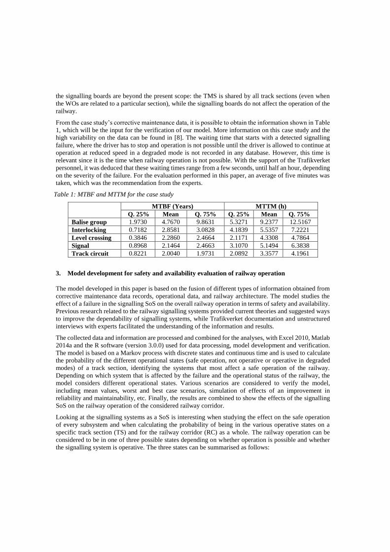
From the case study’s corrective maintenance data, it is possible to obtain the information shown in Table
1, which will be the input for the verification of our model. More information on this case study and the
high variability on the data can be found in [8]. The waiting time that starts with a detected signalling
failure, where the driver has to stop and operation is not possible until the driver is allowed to continue at
operation at reduced speed in a degraded mode is not recorded in any database. However, this time is
relevant since it is the time when railway operation is not possible. With the support of the Trafikverket
personnel, it was deduced that these waiting times range from a few seconds, until half an hour, depending
on the severity of the failure. For the evaluation performed in this paper, an average of five minutes was
taken, which was the recommendation from the experts.
Table 1: MTBF and MTTM for the case study
MTBF (Years) MTTM (h)
Q. 25% Mean Q. 75% Q. 25% Mean Q. 75%
Balise group 1.9730 4.7670 9.8631 5.3271 9.2377 12.5167
Interlocking 0.7182 2.8581 3.0828 4.1839 5.5357 7.2221
Level crossing 0.3846 2.2860 2.4664 2.1171 4.3308 4.7864
Signal 0.8968 2.1464 2.4663 3.1070 5.1494 6.3838
Track circuit 0.8221 2.0040 1.9731 2.0892 3.3577 4.1961
3. Model development for safety and availability evaluation of railway operation
The model developed in this paper is based on the fusion of different types of information obtained from
corrective maintenance data records, operational data, and railway architecture. The model studies the
effect of a failure in the signalling SoS on the overall railway operation in terms of safety and availability.
Previous research related to the railway signalling systems provided current theories and suggested ways
to improve the dependability of signalling systems, while Trafikverket documentation and unstructured
interviews with experts facilitated the understanding of the information and results.
The collected data and information are processed and combined for the analyses, with Excel 2010, Matlab
2014a and the R software (version 3.0.0) used for data processing, model development and verification.
The model is based on a Markov process with discrete states and continuous time and is used to calculate
the probability of the different operational states (safe operation, not operative or operative in degraded
modes) of a track section, identifying the systems that most affect a safe operation of the railway.
Depending on which system that is affected by the failure and the operational status of the railway, the
model considers different operational states. Various scenarios are considered to verify the model,
including mean values, worst and best case scenarios, simulation of effects of an improvement in
reliability and maintainability, etc. Finally, the results are combined to show the effects of the signalling
SoS on the railway operation of the considered railway corridor.
Looking at the signalling systems as a SoS is interesting when studying the effect on the safe operation
of every subsystem and when calculating the probability of being in the various operative states on a
specific track section (TS) and for the railway corridor (RC) as a whole. The railway operation can be
considered to be in one of three possible states depending on whether operation is possible and whether
the signalling system is operative. The three states can be summarised as follows:

Operative state: In this state, operation is possible and the signalling system is fully operative.
Faulty state: This is the operational state from when the failure occurs and the operation is
stopped until the dispatcher allows continued operation in a degraded mode (40km/h, driver
responsible for supervision and protection).
Degraded state: In this state, the railway operation is possible in a degraded mode (40km/h,
driver responsible for supervision and protection), but the signalling system is not operative due
to a failure in one of the signalling subsystems.
Depending on the subsystem affected by the failure, the three operational states of the railway
infrastructure considered are subdivided, giving a total of 11 states that determine the different operational
states and the state of the signalling SoS (indicating which is the system failed). The states are described
in Table 2. The last two columns of the table show graphically the status of safety and availability, and
how these change depending on the state of the railway: with a “++”OK, “-“ when operating in a degraded
mode and “--“when the signalling system is not ensuring safety or the railway is not available.
Table 2: States
States State of the signalling SoS Railway operation S. Av.
St.1 All operative Operative ++ ++
St.2 BG failed – signalling SoS not operative Faulty (not operative) ++ --
St.3 BG failed – signalling SoS not operative Operative in a degraded mode -- -
St.4 IXL failed – signalling SoS not operative Faulty (not operative) ++ -- St.5 IXL failed – signalling SoS not operative Operative in a degraded mode -- -
St.6 LC failed – signalling SoS not operative Faulty (not operative) ++ --
St.7 LC failed – signalling SoS not operative Operative in a degraded mode -- -
St.8 Signal failed – signalling SoS not operative Faulty (not operative) ++ --
St.9 Signal failed – signalling SoS not operative Operative in a degraded mode -- -
St.10 TC failed – signalling SoS not operative Faulty (not operative) ++ --
St.11 TC failed – signalling SoS not operative Operative in a degraded mode -- -
3.1. Markov theory
Various authors have evaluated the availability and / or safety of railway signalling systems: Markov
Chains [21], Monte Carlo Simulation [22] and Stochastic Petri Nets [23-24] are suitable approaches for
stochastic modelling to evaluate the RAMS of a railway signalling system. RAMS problems are normally
concerned with systems that are discrete in space, i.e., they can exist in one of a number of discrete and
identifiable states and are continuous in time; i.e., they exist continuously in one of the system states until
a transition takes them discretely to another state, in which they then exist continuously until another
transition occurs [25]. In the Swedish railway, previous research has shown the low accuracy of the
corrective maintenance records regarding railway signalling systems [8]. While Hidden Markov models,
Semi-Markov models and Petri nets would include in the evaluation the failures on redundant systems or
components, and the ageing of the system, this would require having further assumptions since some of
the information needed is not possible to obtain. This paper considers the failure rate of a specific time to
evaluate the performance of the railway signalling systems and to support maintenance decisions.
The Markov approach is applicable when handling both repairable and non-repairable systems, under the
following assumptions [25]:

The behaviour of the system must be characterised by a lack of memory; that is, the future states
of a system are independent of all past states except the immediately preceding one:
P(qn|qn−1, qn−2, ..., q1) = P(qn|qn−1). (1)
The process must be stationary (i.e. the probability of making a transition from one given state
to another is the same at all times in the past and future).
Finally, it must be possible to define the different states of the system.
The transition rates from one state into another can be defined as in Equation 2 [25], and the transition
between the different states of the Markov model is given by the failure, restoration and waiting rates (λ,
µo and µw respectively) of each considered system. The transition rates describe not only the reliability of
the process and the design of the components, but also the effectiveness of operation and maintenance
practices [26]; shown as:
Transition rate =number of times a transition occurs from a given state
time spent in the given state (2)
With respect to the transition rate, three time parameters can be defined. The mean operating time between
failures (MTBF) is the expectation of the operating time between failures and can be calculated following
Equation 3, being Δt the time of observation and kF the total number of failure of the items during the
time of observation; the mean time to maintain (MTTM) is the expectation of the time to restore (see
Equation 4), and the mean waiting time (MWT) is the time from the start of the downtime until the driver
is allowed by the dispatcher to continue operation in a degraded operating mode:
MTBF =∑ 𝛥𝑡𝑖
𝑛𝑖=1
𝑘𝐹 (3)
MTTM =Δt
𝑘𝐹 (4)
From Equation 2, the transition between the different states of the Markov model is given by λ, µo and µw
of each system considered (see Equations 5, 6 and 7). In particular, µw measures the rate of systems
staying in the non-operative state.
λ =1
MTBF (5)
µ𝑜 =1
MTTM (6)
µ𝑤 =1
MWT (7)
The probability of being in the operating state after an incremental interval of time dt (made sufficiently
small so that the probability of two or more events occurring during this increment of time is negligible)
is [Prob. of being operative at time t AND not failing in time dt] + [probability of being failed at time t
AND of being repaired in time dt] [25]. For example, for a continuous Markov process with two system
states 1 and 2, as shown in Equation 8, the equation obtained is a linear differential equation with constant
coefficients, which can be solved by Laplace transforms.
[𝑃′1(𝑡) 𝑃′
2(𝑡)] = [𝑃1(𝑡) 𝑃2(𝑡)] [−𝜆 𝜆𝜇 −𝜇
] (8)
Since the probability of occurrence of a transition in this interval of time Δt is equal to the transition rate
times the time interval, the stochastic transitional probability matrix for a continuous Markov process
with two states can be expressed as follows:

P=[1 − 𝜆 Δ𝑡 𝜆 Δ𝑡
𝜇 Δ𝑡 1 − 𝜇 Δ𝑡] (9)
If 𝛼 represents the limiting probability vector of being in the different states, and P is the stochastic
transitional probability matrix, once the limiting state probabilities have been reached by the matrix
multiplication method, and any further multiplication by the stochastic transitional probability matrix
does not change the values of the limiting state probabilities [25], then
𝛼𝑃 = 𝛼 being 𝛼 = [𝑃1 𝑃2] (10)
and
[𝑃1 𝑃2]=[𝑃1 𝑃2] [1 − 𝜆 Δ𝑡 𝜆 Δ𝑡
𝜇 Δ𝑡 1 − 𝜇 Δ𝑡] (11)
Rearranging Equations 10 and 11 allows the use of the stochastic transitional probability matrix simplified
by omitting the Δt terms:
P=[1 − 𝜆 𝜆
𝜇 1 − 𝜇 ] (12)
3.2. Model development
The state-space diagram for the Markov process visualised in Figure 2 shows the different states of the
system (see Table 1 for description) and the possible transitions between them. The stochastic transitional
probability matrix (P) shows the probability of going from one state to another (the probability of going
from state i to state j is equal to Pi,j).
Figure 2: Markov diagram
The possibility of going from a failed state to the operative state (e.g. from the state 2 to the state 1), is
not considered possible, since the inspection of the failure and the restoration action are performed in the
third state (when the railway operation is possible in a degraded mode). It is possible to deduce then the
simplified stochastic transitional probability matrix from Equation 12:

1- λ1,2- λ1,4- λ1,6- λ1,8- λ1,10 λ1,2 0 λ1,4 0 λ1,6 0 λ1,8 0 λ1,10 0
0 1- µ2,3 µ2,3 0 0 0 0 0 0 0 0
µ3,1 0 1- µ3,1 0 0 0 0 0 0 0 0
0 0 0 1- µ4,5 µ4,5 0 0 0 0 0 0
µ5,1 0 0 0 1- µ5,1 0 0 0 0 0 0
0 0 0 0 0 1- µ6,7 µ6,7 0 0 0 0
P= µ7,1 0 0 0 0 0 1- µ7,1 0 0 0 0
0 0 0 0 0 0 0 1- µ8,9 µ8,9 0 0
µ9,1 0 0 0 0 0 0 0 1- µ9,1 0 0
0 0 0 0 0 0 0 0 0 1- µ10,11 µ10,11
µ11,1 0 0 0 0 0 0 0 0 0 1- µ11,1
The system is considered to be fully operative for the initial state expressed as:
P(t=0) = (1,0,0,0,0,0,0,0,0,0,0,0)
3.3. Framework for safety and availability evaluation of the railway operation
The different probability states for a TS can be obtained by the sum of the various probabilities for the
faulty and degraded states, respectively (see Equations 13 and 14), since it can be assumed that it is only
possible to have one failure on a track section at a specific moment in time. The sum of all the probabilities
must be equal to 1, since the operational state is unique in every instant of time (see Equation 15).
𝑃𝐹𝑎𝑢𝑙𝑡𝑦 𝑇𝑆 = ∑ 𝑃𝐹𝑎𝑢𝑙𝑡𝑦(𝑖) (13)
𝑃𝐷𝑒𝑔𝑟𝑎𝑑𝑒𝑑 𝑇𝑆 = ∑ 𝑃𝐷𝑒𝑔𝑟𝑎𝑑𝑒𝑑(𝑖) (14)
𝑃𝑇𝑜𝑡𝑎𝑙 𝑇𝑆 = 𝑃𝑂𝑝𝑒𝑟𝑎𝑡𝑖𝑣𝑒 + 𝑃𝐹𝑎𝑢𝑙𝑡𝑦 𝑇𝑆 + 𝑃𝐷𝑒𝑔𝑟𝑎𝑑𝑒𝑑 𝑇𝑆 = 1 (15)
The availability of the whole railway corridor can be represented by the probabilities of the different
operational states; therefore, the probability of achieving the expected requirements in terms of
punctuality and availability. The probability of all the track sections that comprise the railway corridor
being fully operative can be calculated knowing that the probability of failure for each track section is
independent of the others. For the operative state, the only case for this probability is that all the TS are
in this state (see Equation 16, while the probability of being in a faulty state will be given by the
probability that at least one TS is in that state (see Equation 17). Finally, the probability of being in a
degraded operational mode state will be given by the probability of not being on the operative or faulty
states (Equation 18).
𝑃𝑂𝑝𝑒𝑟𝑎𝑡𝑖𝑣𝑒 𝑅𝐶 = ∏ 𝑃𝑂𝑝𝑒𝑟𝑎𝑡𝑖𝑣𝑒 𝑇𝑆(𝑖)𝑛𝑖 (16)
𝑃𝐹𝑎𝑢𝑙𝑡𝑦 𝑅𝐶 = 1 − ∏ (1 − 𝑃𝐹𝑎𝑢𝑙𝑡𝑦 𝑇𝑆𝑛𝑖 (𝑖)) (17)
𝑃𝐷𝑒𝑔𝑟𝑎𝑑𝑒𝑑 𝑅𝐶 = 1 − 𝑃𝑂𝑝𝑒𝑟𝑎𝑡𝑖𝑣𝑒 𝑅𝐶 − 𝑃𝐹𝑎𝑢𝑙𝑡𝑦 𝑅𝐶 (18)
However, for the purpose of this paper, the different probabilities are calculated assuming the same
probabilities for all track sections (otherwise, a Markov model must be performed for each track section).
4. Analysed scenarios and results
This paper analyses the performance of the signalling SoS on track section level based on the collected
data. Eight scenarios are considered and described in Table 3. These scenarios show the probabilities of

being in the different operational states obtained by the mean failure and restoration rates and enables a
study of the effects of the availability of railway signalling systems and the effects of implementing
different maintenance policies.
The considered scenarios can be divided in two types. In the first type, scenarios F-1 to F-5 are based on
real data gathered from the maintenance databases, from which the MTBF and MTTM have been obtained
for the different track sections that compose the railway corridor of the case study. In the second type,
scenarios S-1 to S-3 are based on the recorded data, but they simulate the impact on the safety and
availability of the railway operation of different maintenance policies for the signalling SoS. Scenario F-
1 represents the mean values obtained from the corrective maintenance data for the track sections on the
studied railway corridor. Scenarios F-2 and F-3 allow studying the effect of the different RAMS variables
(such as the MTBF and the MTTM) on the railway operation to see which has more influence on safe
operation. Scenarios F-4 and F-5 allow to look at the variance between the probability states obtained for
the worst case scenario and the best case scenario observed from the recordings for all track sections on
the railway corridor, looking at the range of values for the MTBF and MTTM (i.e. the lowest reliability
and highest maintainability).
Table 3: Scenarios to model
Scenario Description
F-1 Mean values of the MTBF and MTTM
F-2 Mean values of the MTBF and 75% quartile of the MTTM
F-3 25% quartile of the MTBF and mean values of the MTTM
F-4 Worst case scenario: 25% quartile of the MTBF and 75% quartile of the MTTM
F-5 Best case scenario: 75% quartile of the MTBF and 25% quartile of the MTTM
S-1 Simulation with a 50% increase of the MTBF and mean values of the MTTM
S-2 Simulation with a 25% reduction of the MTBF and 25% reduction on the MTTM
S-3 Simulation with a 50% reduction of the MTTM and mean values of the MTBF
Finally, scenarios S-1, S-2 and S-3 simulate the probabilities obtained when improving the reliability of
the SoS (increasing MTBF in scenario S-1 by 50%), combining an improvement in reliability and
maintainability simultaneously (increasing MTBF by 25% and decreasing MTTM by 25% in scenario S-
2), or improving the maintainability (reducing MTTM by 50% in scenario S-3). By studying these
scenarios (S-1 to S-3), it is possible to identify the effects of different maintenance policies on the safety
and availability of the railway operation.
4.1. Results obtained for the scenarios F-1 to F-5
Tables 4 to 7 show the relative probabilities between states. For the operative state, it is desirable to
achieve a probability state that is as high as possible, but for faulty and degraded states, the lowest one
will give the best results for safety and availability. Table 4 shows the probabilities of being in the
different states for scenarios F-1 to F-5. Figure 3 shows graphically the state probabilities. This allows
comparing the results, looking at the performance variance in a real track section.

Figure 3: Probabilities of the different states for the real data scenarios (F-1 to F-5)
Table 4: Percentages of the probabilities of being at different states for the real data scenarios (F-1 to F-
5)
States Scenario
F-1 F-2 F-3 F-4 F-5
St.1 Operative state 99.863 99.835 99.535 99.449 99.920
St.2 Faulty - BG Failed 0.003 0.003 0.006 0.006 0.001
St.3 Degraded – BG Failed 0.022 0.030 0.053 0.072 0.006
St.4 Faulty. – IXL Failed 0.004 0.004 0.017 0.017 0.004
St.5 Degraded – IXL Failed 0.022 0.029 0.088 0.114 0.016
St.6 Faulty - LC Failed 0.005 0.005 0.032 0.032 0.005
St.7 Degraded – LC Failed 0.022 0.024 0.128 0.141 0.010
St.8 Faulty –Signal Failed 0.006 0.006 0.014 0.014 0.005
St.9 Degraded – Signal Failed 0.027 0.034 0.065 0.081 0.014
St.10 Faulty - TC Failed 0.006 0.006 0.015 0.015 0.006
St.11 Degraded – TC Failed 0.019 0.024 0.046 0.058 0.012
Figure 3 shows a difference between the values obtained for the state probabilities for the various
scenarios. For example, for the LC, the state probability of being in a degraded state obtained for scenario
F-4 is 14 times the one obtained for the F-5 scenario. This difference is also remarkable for the BG (11
times). The differences are minor for faulty states, even though they remain identifiable: six times for the
faulty state linked to the LC and five times for the one linked to the BG.
There is also a difference between the probabilities of the different scenarios of the system most affecting
the railway operation. For example, for scenarios F-1 and F-2, the maximum probability of being in a
faulty state is linked to a failure of the TC, and the maximum probability of being in a degraded state is
linked to a failure of a signal. For scenarios F-3 and F-4, the maximum probabilities for both the faulty
state and the degraded state are related to the LC. For scenario F-5, the maximum probability of being in
a faulty state is related to the TC and to the IXL for a degraded state.
The smallest difference between the state probabilities occurs for the LC and the TC in scenario F-5,
where the probability of being in a degraded state is two times higher than the probability of being in a

faulty state. The maximum difference is obtained for the BG in scenario F-4, with a probability of being
in a degraded state that is 11 times higher than the probability of not being operative.
4.2. Results obtained for the scenarios F-1 and S-1 to S-3
Table 5 shows the probabilities of being in different states for scenarios F-1 and S-1 to S-3. The
corresponding values are visualised in Figure 4, where the recorded mean values and the possible effects
of different maintenance policies on safety and availability of a track section can be compared.
Figure 4: Probabilities of the different states for the mean values scenario (F-1) and the simulation
scenarios (S-1 to S-3)
The highest probability of being in an operational state is obtained for scenario S-2. The probability of
being in a degraded state is 1.5 times higher for scenario S-1 and S-3 than for scenario F-1. For scenario
S-2 this difference is increased to 1.7 times higher than for scenario F-1.
Table 5: Percentages of the probabilities of different states for the mean values scenario (F-1) and the
simulation scenarios (S-1 to S-3)
States Scenario
F-1 S-1 S-2 S-3
St.1 Operative state 99.863 99.909 99.913 99.901
St.2 Faulty - BG Failed 0.003 0.002 0.002 0.003
St.3 Degraded – BG Failed 0.022 0.015 0.013 0.015
St.4 Faulty. – IXL Failed 0.004 0.003 0.004 0.004
St.5 Degraded – IXL Failed 0.022 0.015 0.013 0.015
St.6 Faulty - LC Failed 0.005 0.004 0.004 0.005
St.7 Degraded – LC Failed 0.022 0.014 0.013 0.014
St.8 Faulty –Signal Failed 0.006 0.004 0.005 0.006
St.9 Degraded – Signal Failed 0.027 0.018 0.016 0.018
St.10 Faulty - TC Failed 0.006 0.004 0.005 0.006
St.11 Degraded – TC Failed 0.019 0.013 0.012 0.013

Scenario S-3 and scenario F-1 have the same values for the faulty states. However, it is possible to see an
improvement in scenarios S-1 (1.5 times the values obtained for F-1) and S-2 (1.7 times the values
obtained for F-1). The reduction is less for the operational states; here, the improvement in reliability is
only 25% instead of 50% as in scenario S-1, and there is no improvement for scenario S-3.
4.3. Results obtained for the track section and railway corridor
Table 6 shows the summarised results for the probabilities of a track section being in one of the three
operational states, independent of the failed system. The probability of being in a faulty state is four times
higher in scenario F-4 than in scenario F-5, and the variance of the probability of being in a degraded
state is up to eight times higher.
The results for the simulations of different maintenance policies are similar to the results obtained in
section 5.2. The highest increase of the probability of being operational is obtained for scenario S-2, which
also has the highest reduction in the probability of being in a degraded state. However, the maximum
reduction for the faulty state occurs in scenario S-1.
Table 6: Percentages of the probabilities of the different states for each scenario for the track section
States Scenario
F-1 F-2 F-3 F-4 F-5 S-1 S-2 S-3
Operative state 99.863 99.835 99.535 99.449 99.920 99.909 99.913 99.901
Faulty state 0.024 0.024 0.085 0.085 0.022 0.016 0.020 0.024
Degraded state 0.112 0.140 0.380 0.466 0.058 0.075 0.067 0.075
Finally, Table 7 shows the results of the state probabilities obtained for the whole railway corridor. This
is where the effects of a failure on the railway operation can be observed, since it not only considers the
failure of the systems found on a track section, but also the number of track sections a train drives through
when going from one location to another.
Table 7: Percentages of the probabilities of the different states for each scenario for the railway corridor
States Scenario
F-1 F-2 F-3 F-4 F-5 S-1 S-2 S-3
Operative state 93.393 92.087 79.210 75.868 96.098 95.544 95.746 95.156
Faulty state 1.213 1.212 4.147 4.144 1.079 0.810 0.972 1.213
Degraded state 5.394 6.700 16.643 19.988 2.823 3.645 3.282 3.631
For the considered railway corridor, the percentage of probability of a train having all track sections
operative is between 76% and 96%. With the different simulations of the maintenance policies, the
probability of being in an operational state could be improved by reducing the probability of being in a
degraded state (in the case of S-3), or by reducing the probabilities of being in both faulty and degraded
states (S-1 and S-2). Again, the maximum improvement on the operation is given in scenario S-2 where
there is an improvement of both the failure and repair rate, while the highest reduction in the probability
of being in a faulty state is obtained for scenario S-1.
5. Discussion
Since this research is based on the corrective maintenance affecting operation (supervision, protection,
control, information) recorded in the database 0felia, it does not take into account corrective maintenance
that could have been done but not recorded, e.g. during inspections. The use of real maintenance data
makes the research process more complex, but renders the results more relevant since they reflect the

complexity of reality. To increase the quality of the maintenance records (for example, recording the
component affected, reducing the “not defined” failure modes or recording if the failure affects the
railway operation) would increase the reliability of the obtained results.
A Markov model is developed to calculate the probability of the three operational states (operative, faulty
or degraded) of a track section, identifying the systems that most affect the safe operation of the railway.
The model was used to evaluate the operational effects of dependability improvements of different
signalling assets and then verified with a case study of a Swedish railway signalling system using a
number of scenarios. The Markov model is a tool for maintainers to use when evaluating the safety and
availability of the railway operation by analysing the times when operation is possible but the signalling
system is not ensuring safety; it also allows simulating the effects of different RAMS improvements. Its
simplicity allows using the actual maintenance records to obtain an estimation of the level of safety and
availability, despite the lack of detailed data (which would be needed if implementing a more complex
model). Further work can be oriented to investigate better models that can give a better estimation of the
probabilities, by taking into account the failure and repair distributions.
Depending on the performance of the signalling system, new actions can be taken to achieve
improvements, and the model can simulate the effects of these on both safety and availability, not only
with regard to potential delays or cancellations, but also considering safe operation and the reduction of
the probability of operation in a degraded state.
The probability of being in a state where operation is possible in a degraded mode is higher than the
probability of not being operative at all. Operating the railway in a degraded state can reduce the delays
caused by a failure of the signalling system, but this does not change the fact that the signalling system is
failed and, hence, safety cannot be ensured. In order to evaluate the safety and availability of the railway,
we must not only look into reliability and maintainability (i.e. considering failures and delays) but also
consider the probability of operation in a degraded mode. From a safety perspective, the better option is
signalling system with lower reliability but a safer design than one with higher reliability but with a higher
probability of operating in a degraded mode.
The differences in the results obtained for scenarios F-1 to F-5 can be linked to the fact that these results
are obtained from operational instead of inherent reliability and maintainability data. Hence, other factors
related to the environment, operation, etc. can influence the behaviour of the systems. The logistics related
to the waiting time for performing corrective maintenance in a certain location also play an important role
in the real repair rates. Maintenance improvements can be oriented, for example, to reduce the waiting
time related to logistics if it is necessary to reduce the degraded operational mode.
The probabilities of being in a faulty state are the same for scenarios S-3 and F-1 because the increased
probability of being operative is based on a reduction in the repair rate that only affects the degraded
states. The probability of being in a faulty state is reduced for scenarios S-1 and S-2 because the
improvement is based on a global reduction of the failure rate, which affects all the states. The highest
improvement in operational time is obtained for scenario S-2 by combining measures to reduce both the
repair and the failure rate, which also gives the highest reduction in the probability of being in a degraded
state.
A reduction of MTTM can be obtained by improving the maintainability or the maintenance support
performance (e.g. reducing the logistics time, optimising maintenance time by increasing personnel
expertise, etc.). A reduction of the MTBF can be obtained by improving the inherent reliability of the
systems by reducing the external factors, reducing the number of assets needed for a track section,
implementing condition based maintenance methods for failure diagnostics and prognostics and/or
improving the preventive maintenance, etc. Another important consideration when looking for the best

maintenance strategy is the cost associated with each improvement; of course, this will depend on the
specific situation. The best maintenance policy is reached when the minimum requirements of safety are
met. If this is already optimum, the best option is to improve the probability of the operational state.
This paper has used the 50%, 25% and 75% quartiles to show the range of variation that can be obtained
when implementing the model, depending on the input data. The choice of these values is more for the
purpose of easy visibility than anything else. The results of other simulations using the median, absolute
maximums and minimums, and 5% and 10% quartiles show no relevant differences.
6. Conclusions
This paper proposes a framework to evaluate the safety and availability of railway operation, by
quantifying the probability of the signalling system not to supervise the railway traffic. The following
conclusions can be drawn:
The proposed methodology is successful on evaluating the safety and availability of the railway
operation, focusing on railway signalling systems.
The results obtained from the model show that the probability of being in a state where operation
is possible in a degraded mode is greater than the probability of not being operative at all, which
reduces delays, but requires other risk mitigation measures to ensure safe operation.
Operational and environmental factors may have a great influence on the safety of the railway
operation. Further work can be oriented to identify and measure the effects of external factors
that can affect the performance of railway signalling systems.
Combining maintenance improvements to reduce the failure rate and increase the repair rate is
more efficient at increasing the probability of being in an operative state and reducing the
probability of operating in a degraded state than to only reducing the failure rate or increasing
the repair rate.
Even though this research has used the case study of the Swedish signalling system to verify the model,
it can be generalised to other types of signalling systems or railway networks. Further research can be
focused on the application of this method to evaluate and compare the performance of the signalling SoS
from different locations, architectures or design solutions, thereby assisting in the decision-making
process when improving or updating the railway infrastructure.
FUNDING
This research received financial support from Luleå Railway Research Center (JVTC) and Trafikverket.
ACKNOWLEDGEMENTS
The authors gratefully acknowledge the financial and intellectual support of Luleå Railway Research
Center (JVTC) and the Swedish Transport Administration (Trafikverket). The authors gratefully
acknowledge the valuable support and discussions of Dr. Jing Lin and Dr. Amir Soleimani Garmabaki.
References
[1] Vernez D, Vuille F. Method to assess and optimise dependability of complex macro-systems:
Application to a railway signalling system. Safety Science 2009; 47(3): 382-394.
[2] Louit DM, Pascual R, Jardine AKS. A practical procedure for the selection of time to failure
models based on the assessment of trends in maintenance data, Reliability Engineering & System
Safety, 2009; 94(10): 1618-1628.
[3] Sun Y, Fidge C, Ma L. Reliability prediction of long-lived linear assets with incomplete failure
data, in 2011 International Conference on Quality, Reliability, Risk, Maintenance, and Safety
Engineering (ICQR2MSE); pp. 143-147.
[4] EN 50126: 1999, Railway Applications – The specification and demonstration of Reliability,
Availability, Maintainability and Safety (RAMS), European Committee for Electrotechnical
Standardization (CENELEC), Brussels, Belgium.
[5] Alexandersson G, Hultén S. The Swedish Railway Deregulation Path, Review of Network
Economics, 2008; 7(1): 18-36.
[6] Baldwin WC, Felder WN, Sauser BJ. Taxonomy of increasingly complex systems, International
Journal of Industrial and Systems Engineering, 2011; 9(3): 298–316.
[7] Dorj E, Chen C, Pecht M. A Bayesian Hidden Markov Model-based approach for anomaly
detection in electronic systems, in IEEE Aerospace Conference Proceedings, 2013.
[8] Morant A, Larsson-Kråik P-O, Kumar U. Data-driven model for maintenance decision support - a
case study of railway signalling systems. Institution of Mechanical Engineers. Proceedings. Part
F: Journal of Rail and Rapid Transit, 2014. DOI: 10.1177/0954409714533680
[9] EN 50126-2: 2007, Railway Applications – The specification and demonstration of Reliability,
Availability, Maintainability and Safety (RAMS) – Part 2: Guide to the application of EN 50126-
1 for safety, European Committee for Electrotechnical Standardization (CENELEC), Brussels,
Belgium.
[10] Restel FJ. The Markov reliability and safety model of the railway transportation, Safety and
reliability: methodology and applications, Nowakowski et al. (eds.), Taylor & Francis Group,
London, 2015.
[11] Chandra V, Kumar KV. Reliability and safety analysis of fault tolerant and fail safe node for use
in a railway signalling system, Reliability Engineering and System Safety, 1997; 57(2): 177-183.
[12] Tao C. A two-stage safety analysis model for railway level crossing surveillance systems, in 2009
IEEE International Conference on Control and Automation, 2009; pp. 1497.
[13] Anik VG., Ustoglu I, Kaymakci OT. The functional safety calculation of a real interlocking system
in Turkey, in 2011 IEEE International Conference on Mechatronics, ICM 2011 - Proceedings,
2011; pp. 71.
[14] Tan P, He W, Lin J, Zhao H, Chu J. Design and reliability, availability, maintainability, and safety
analysis of a high availability quadruple vital computer system, Journal of Zhejiang University:
Science A, 2011; 12(12): 926-935.
[15] Brkic R, Adamovic Z. Research of defects that are related with reliability and safety of railway
transport system, Russian Journal of Nondestructive Testing, 2011, vol. 47, no. 6, pp. 420-429.
[16] Kohlik M, Kubatova H. Markov chains hierarchical dependability models: Worst-case
computations, LATW 2013 - 14th IEEE Latin-American Test Workshop, 2013.
[17] Bondavalli A, Nelli M, Simoncini L, Mongardi G. Hierarchical modelling of complex control
systems: Dependability analysis of a railway interlocking, Computer Systems Science and
Engineering, 2001; 16(4): 249-261.
[18] Trafikverket. Railway infrastructure architecture on Trafikverket (Anläggningsstruktur järnväg
inom Trafikverket), Standard BVS 811, Trafikverket, Borlänge, 2012.
[19] Theeg G; Vlasenko S. Railway Signalling & Interlocking - International Compendium, Eurailpress
2009.
[20] Trafikverket. Manual – use of 0felia for analysis (Handledning - att använda Ofelia för
analytiker). Report, Trafikverket, Borlänge, 2010.
[21] Chen H, Qian Y. Reliability and safety analysis of cross-redundant Structure based on Markov
process, Proceedings - 2012 5th International Symposium on Computational Intelligence and
Design, ISCID 2012, 2012, pp. 406.
[22] Hasanzadeh Z, Sandidzadeh MA. The reliability evaluation of interlocking system for improving
the operation factors - A case study in Tehran metro, Proceedings of the IASTED International
Conference on Modelling and Simulation, 2008, pp. 274.
[23] Adamyan A, He D. System failure analysis through counters of Petri net models, Quality and
Reliability Engineering International, 2004; 20(4): 317-335.
[24] Patra AP, Kumar U. Availability analysis of railway track circuits, Proceedings of the Institution
of Mechanical Engineers, Part F: Journal of Rail and Rapid Transit, 2010; 224(3): 169-177.
[25] Billinton R, Allan RN. Reliability Evaluation of Engineering Systems – Concepts and Techniques,
Plenum Press, New York, NY, 1992, pp. 260–308.
[26] Lipsett MG, Gallardo-Bobadilla R. Modelling Risk in Discrete Multi-State Repairable Systems,
Asset Condition, Information Systems and Decision Models, Engineering Asset Management
Review, 2013, Springer, pp. 187–205. DOI: 10.1007/978-1-4471-2924-0_10