safety recall p37 / nhtsa 14v-392 rear suspension … recall p37 / nhtsa 14v-392 rear suspension...
TRANSCRIPT

Copyright 2014, Chrysler Group LLC, All Rights Reserved (wah)
Revised September 2014 Dealer Service Instructions for:
Safety Recall P37 / NHTSA 14V-392
Rear Suspension Shock Absorbers
NOTE: The shock absorber sales codes in the “Parts Information” section have
been revised.
2014 (DS) RAM Pick Up Truck (1500 series)
NOTE: This recall applies only to the above vehicles built with Hitachi rear shock
absorbers from May 21, 2014 through June 05, 2014 (MDH 052100 through 060522).
2014 (KL) Jeep Cherokee
NOTE: This recall applies only to the above vehicles built with Hitachi rear shock
absorbers from May 21, 2014 through June 06, 2014 (MDH 052100 through 060602).
2015 (UF) Chrysler 200 Sedan
NOTE: This recall applies only to the above vehicles built with Hitachi rear shock
absorbers from May 21, 2014 through June 05, 2014 (MDH 052100 through 060521).
The rear suspension shock absorbers on about 20,300 of the above vehicles may
break the upper or lower attachment ring. A partially detached rear suspension
shock absorber(s) could cause damage to other rear chassis/suspension
components, rear brake tube damage and/or damage to the rear tire(s). This could
cause a crash without warning.
Models
IMPORTANT: Some of the involved vehicles may be in dealer new vehicle
inventory. Federal law requires you to complete this recall service on these
vehicles before retail delivery. Dealers should also consider this requirement to
apply to used vehicle inventory and should perform this recall on vehicles in for
service. Involved vehicles can be determined by using the VIP inquiry process.
Subject

Safety Recall P37 – Rear Suspension Shock Absorbers Page 2
Both rear suspension shock absorber build date codes must be inspected. Shock
absorbers found within a suspect build date range will be replaced.
Part Number Description
CBA0P371AA Shock Absorber (DS models with sales code SER)
CBA0P372AA Shock Absorber (DS models without sales code SER
and with sales code SGD)
CBA0P373AA Shock Absorber (DS models without sales code SER,
with sales code SGB and either sales codes (5ZK and 5ZE)
or (5ZJ and 5ZF) or (5ZJ and 5ZE) or (5AX and 5ZG))
CBA0P374AA Shock Absorber (DS models without sales code SER, with
sales code SGB and 5AX and 5ZE)
CBA0P375AA Shock Absorber (KL models with sales code SDF)
CBA0P376AA Shock Absorber (KL models with sales codes SDJ and 5I4)
CBA0P377AA Shock Absorber (KL models with sales codes SDA and 5I2)
CBA0P378AA Shock Absorber (KL models with sales codes SDA and 5I4)
CBA0P379AA Shock Absorber (UF models)
Due to the small number of involved vehicles expected to require rear suspension
shock absorber replacement, no parts will be distributed initially. Rear
suspension shock absorber(s) should be ordered only after inspection
determines that replacement is required. Very few vehicles are expected to
require rear suspension shock absorber replacement.
Part Number Description
05066440AA Zipper Lube
(NOTE: One bottle will service 25 shock absorbers)
Repair
Parts Information
Safety Recall P37 – Rear Suspension Shock Absorbers Page 3
The following special tools are required to perform this repair:
NPN wiTECH VCI Pod Kit
NPN Laptop Computer
NPN wiTECH Software
Special Tools
Safety Recall P37 – Rear Suspension Shock Absorbers Page 4
A. Inspect Rear Suspension Shock Absorber Date Code
1. Lift the vehicle on an appropriate hoist.
2. Remove the rear wheels to gain access to the rear suspension shock absorber date
code labels located on the body of the rear suspension shock absorbers.
3. Using a shop towel, clean the label on the rear suspension shock absorbers.
4. Inspect the date code on both rear suspension shock absorbers (Figures 1 and 2):
If the rear suspension shock absorber date code is before day 141 or after day
148 no further action is required. Install the rear wheels, remove the vehicle
from the hoist and return the vehicle to the customer.
If the rear suspension shock absorber date code is on or between day 141 and
day 148, the rear suspension shock absorber must be replaced. Continue with
Section B. for DS models or Section C. for KL and UF models.
If the rear suspension shock absorber date code on the rear suspension shock
absorber label is not legible, replace the rear suspension shock absorber.
Continue with Section B. for DS models, Section C. for KL or UF models.
Service Procedure

Safety Recall P37 – Rear Suspension Shock Absorbers Page 5
Service Procedure
Figure 1 – Shock Absorber Date Code and Label Location (KL / UF Models)
DATE CODE IS THE THREE CENTER
NUMBERS (274TH
DAY)
3 = YEAR BUILT (2013)
REAR BRAKE
ROTOR
REAR SUSPENSION
SHOCK ABSORBER
REAR SUSPENSION SPRING
Safety Recall P37 – Rear Suspension Shock Absorbers Page 6
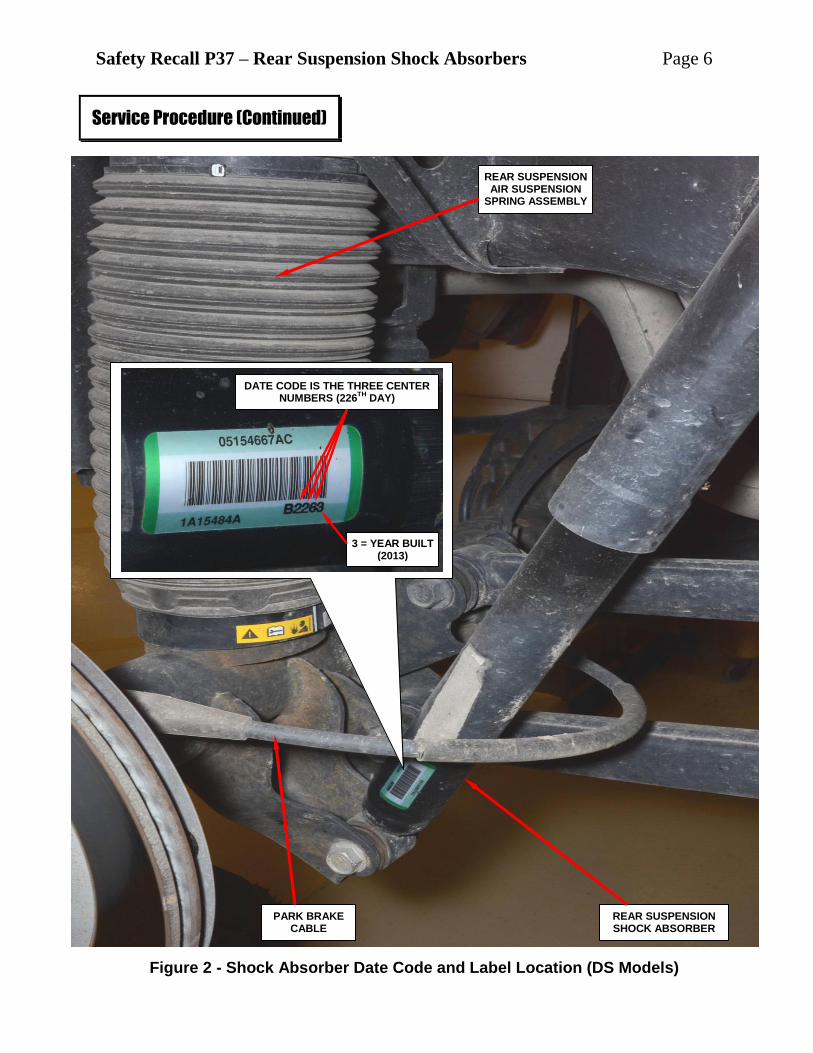
Service Procedure (Continued)
DATE CODE IS THE THREE CENTER NUMBERS (226
TH DAY)
3 = YEAR BUILT (2013)
REAR SUSPENSION SHOCK ABSORBER
PARK BRAKE CABLE
REAR SUSPENSION AIR SUSPENSION
SPRING ASSEMBLY
Figure 2 - Shock Absorber Date Code and Label Location (DS Models)

Safety Recall P37 – Rear Suspension Shock Absorbers Page 7
B. Replace Rear Suspension Shock Absorber (DS Models)
NOTE: The following procedure is required if the rear suspension shock
absorber(s) require replacement per the inspection in Section “A.”
1. For vehicles equipped with air suspension, lower the vehicle from the hoist.
2. For vehicles equipped with air suspension, perform the following procedure:
a. Connect the wiTECH scan tool to the vehicle.
b. Start a wiTECH session.
c. From the “Vehicle View” screen, select the “ASCM” icon.
d. Select the “Misc. Functions” tab.
e. Select “Disable Level Control” and follow the wiTECH screen prompts.
f. From the “Misc. Functions” tab
screen, run the “Spring Deflate to
Reservoir” routine on the air
suspension spring next to the shock
absorber being replaced.
g. Repeat Step 2f. three times.
3. For vehicles equipped with air
suspension, raise vehicle on the hoist.
4. Remove and save the plastic wheel
house liner.
5. Support the rear axle with a suitable
jack stand.
6. Remove and save the shock absorber
upper bolt and nut (Figure 3).
7. Remove and save the shock absorber
lower bolt and nut (Figure 3).
Service Procedure (Continued)
Figure 3 – Upper and Lower Shock Absorber Bolts and Nuts
LOWER BOLT AND NUT
REAR SUSPENSION
SHOCK ABSORBER
UPPER BOLT AND NUT

Safety Recall P37 – Rear Suspension Shock Absorbers Page 8
8. Remove and discard the rear suspension shock absorber from the vehicle.
9. Position the new rear suspension shock absorber in the shock absorber
mounting brackets.
10. Install the upper shock absorber bolt and nut finger tight (Figure 3).
11. Install the lower shock absorber bolt and nut finger tight (Figure 3).
12. Tighten the upper and lower shock absorber bolts and nuts to 100 ft. lbs.
(135 N·m).
13. Remove the jack stand supporting the rear axle.
14. Install the plastic wheel house liner.
15. Install the rear wheel(s) and tighten the lug nuts to 100 ft. lbs. (135 N·m).
16. Lower the vehicle from the hoist.
17. For vehicles equipped with air suspension, use the wiTECH scan tool to
perform the following procedure:
a. From the vehicle view screen, select the “ASCM” icon.
b. Select the “Misc. Functions” tab.
c. Run the “Fill Spring from Reservoir” routine on the spring that was
deflated. Choose the “Complete Fill” option from the menu selections.
d. Follow the wiTECH screen prompts.
NOTE: If the spring will not fill, check for an active DTC. All DTC’s must
be stored before the spring will fill. If DTC C2212-00 is active, run the
“Disable Level Control” routine again to get the active DTC to become a
stored DTC.
18. Remove the wiTECH scan tool from the vehicle.
19. Return the vehicle to the customer.
Service Procedure (Continued)

Safety Recall P37 – Rear Suspension Shock Absorbers Page 9
C. Replace Rear Suspension Shock Absorber (KL or UF Models)
NOTE: The following procedure is
required if the rear suspension
shock absorber(s) require
replacement per the inspection in
Section “A.”
1. Remove and save the wheel house
liner.
2. Support the rear suspension arm
with a suitable jack stand.
3. Remove and save the bolt securing the lower end of the rear suspension shock
absorber assembly to the lower knuckle assembly (Figure 4).
4. Remove and save the upper
aluminum shock absorber mount
retaining bolts (Figure 5).
CAUTION: Due to close
proximity of fuel filler tube to
the right side upper shock
absorber mounting bolts, it
may be necessary to loosen fuel
filler tube bolt to the body to
fully gain access to the bolts
and prevent damage to the fuel
filler tube during shock
absorber removal (Figure 5).
Service Procedure (Continued)
LOWER KNUCKLE
REAR SUSPENSION SHOCK ABSORBER
LOWER BOLT
Figure 4 – Lower Shock Absorber Bolt
Figure 5 – Upper Aluminum Shock Absorber Mount Retaining Bolts
UPPER ALUMINUM SHOCK ABSORBER
MOUNT
UPPER ALUMINUM SHOCK ABSORBER MOUNT RETAINING BOLTS
FUEL FILLER TUBE
REAR SUSPENSION SHOCK ABSORBER

Safety Recall P37 – Rear Suspension Shock Absorbers Page 10
5. Remove the rear suspension shock absorber assembly from the vehicle.
6. Use the following procedure to transfer the upper aluminum shock absorber
mount to the new rear suspension shock absorber:
a. Place the original rear suspension shock absorber in a bench vise.
b. Use tool WTC-P37, or equivalent, to hold the rear suspension shock
absorber shaft from turning during retaining nut removal (Figure 6).
c. Use tool WTC-P37, or equivalent, to remove retaining nut that holds the rear
suspension shock absorber upper aluminum mount to the shock absorber
shaft (Figure 6).
NOTE: The shock absorber tools referenced above can be purchased
through Wright Tool Company at dealer expense. Call 800-783-9826
and select “2 for Sales”. Please have your dealer code and a contact
name available when calling.
Service Procedure (Continued)
Figure 6 – Remove/Install Shock Absorber Shaft Nut
UPPER ALUMINUM SHOCK ABSORBER
MOUNT
SHOCK ABSORBER
SHAFT HOLDER
SHOCK ABSORBER SHAFT NUT
SOCKET
Safety Recall P37 – Rear Suspension Shock Absorbers Page 11
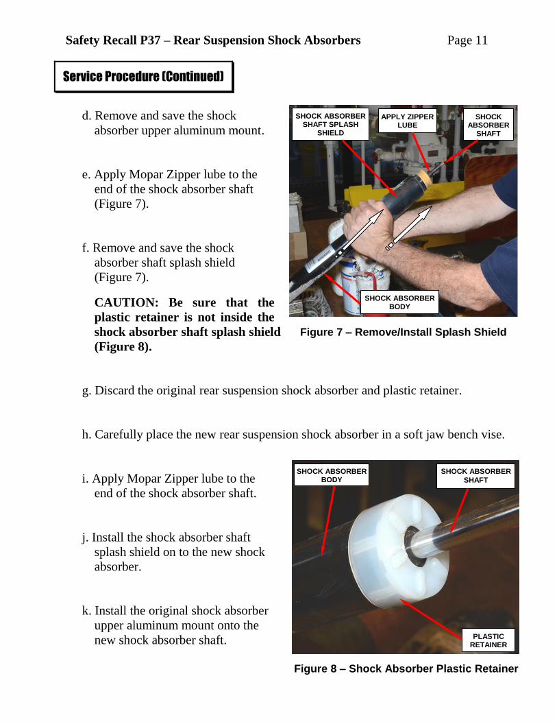
d. Remove and save the shock
absorber upper aluminum mount.
e. Apply Mopar Zipper lube to the
end of the shock absorber shaft
(Figure 7).
f. Remove and save the shock
absorber shaft splash shield
(Figure 7).
CAUTION: Be sure that the
plastic retainer is not inside the
shock absorber shaft splash shield
(Figure 8).
g. Discard the original rear suspension shock absorber and plastic retainer.
h. Carefully place the new rear suspension shock absorber in a soft jaw bench vise.
i. Apply Mopar Zipper lube to the
end of the shock absorber shaft.
j. Install the shock absorber shaft
splash shield on to the new shock
absorber.
k. Install the original shock absorber
upper aluminum mount onto the
new shock absorber shaft.
Service Procedure (Continued)
Figure 7 – Remove/Install Splash Shield
SHOCK ABSORBER BODY
Figure 8 – Shock Absorber Plastic Retainer
PLASTIC RETAINER
SHOCK ABSORBER
SHAFT
SHOCK ABSORBER BODY
SHOCK ABSORBER SHAFT SPLASH
SHIELD
APPLY ZIPPER LUBE
SHOCK ABSORBER
SHAFT
Safety Recall P37 – Rear Suspension Shock Absorbers Page 12
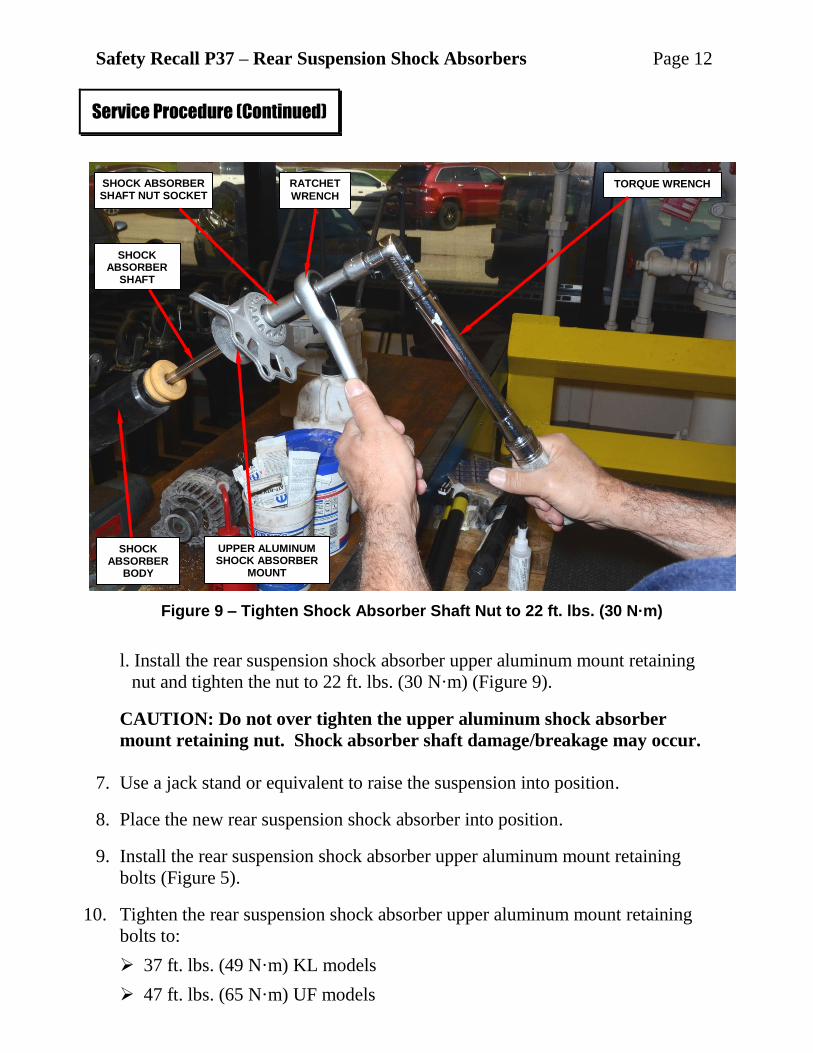
l. Install the rear suspension shock absorber upper aluminum mount retaining
nut and tighten the nut to 22 ft. lbs. (30 N·m) (Figure 9).
CAUTION: Do not over tighten the upper aluminum shock absorber
mount retaining nut. Shock absorber shaft damage/breakage may occur.
7. Use a jack stand or equivalent to raise the suspension into position.
8. Place the new rear suspension shock absorber into position.
9. Install the rear suspension shock absorber upper aluminum mount retaining
bolts (Figure 5).
10. Tighten the rear suspension shock absorber upper aluminum mount retaining
bolts to:
37 ft. lbs. (49 N·m) KL models
47 ft. lbs. (65 N·m) UF models
Service Procedure (Continued)
Figure 9 – Tighten Shock Absorber Shaft Nut to 22 ft. lbs. (30 N·m)
TORQUE WRENCH RATCHET
WRENCH
SHOCK ABSORBER SHAFT NUT SOCKET
UPPER ALUMINUM SHOCK ABSORBER
MOUNT
SHOCK ABSORBER
BODY SPLASH SHIELD
SHOCK ABSORBER
SHAFT

Safety Recall P37 – Rear Suspension Shock Absorbers Page 13
11. Position the lower end of the shock absorber to the knuckle assembly (Figure 4).
12. Install the lower shock absorber retaining bolt and tighten to 139 ft. lbs.
(185 N·m) (Figure 4).
13. Remove the jack stand.
14. Install the wheel house liner.
15. Install both rear tire and wheel assemblies. Tighten lug nuts to 100 ft. lbs.
(135 N·m).
16. Lower the vehicle from the hoist.
17. Return the vehicle to the customer.
Service Procedure (Continued)

Safety Recall P37 – Rear Suspension Shock Absorbers Page 14
Claims for vehicles that have been serviced must be submitted on the
DealerCONNECT Claim Entry Screen located on the Service tab. Claims
submitted will be used by Chrysler to record recall service completions and
provide dealer payments.
Use the following labor operation numbers and time allowances:
Labor Operation Time
Number Allowance
Inspect both rear suspension shock
absorber date codes (All Models) 02-P3-71-81 0.3 hours
Inspect both rear suspension shock
absorber date codes and replace
one rear suspension shock absorber 02-P3-71-82
DS models 0.6 hours
UF / KL models 0.8 hours
Inspect both rear suspension shock
absorber date codes and replace
both rear suspension shock absorbers 02-P3-71-83
DS models 0.9 hours
UF / KL models 1.2 hours
Optional Equipment
Air Suspension (DS Models Only)
(One rear shock absorber) 02-P3-71-60 0.2 hours
(Both rear shock absorbers) 02-P3-71-61 0.3 hours
Add the cost of the recall parts package plus applicable dealer allowance to your
claim.
NOTE: See the Warranty Administration Manual, Recall Claim Processing
Section, for complete recall claim processing instructions.
Completion Reporting and Reimbursement
Safety Recall P37 – Rear Suspension Shock Absorbers Page 15
To view this notification on DealerCONNECT, select “Global Recall System” on
the Service tab, then click on the description of this notification.
All involved vehicle owners known to Chrysler are being notified of the service
requirement by first class mail. They are requested to schedule appointments for this
service with their dealers. A generic copy of the owner letter is attached.
Enclosed with each owner letter is an Owner Notification postcard to allow owners
to update our records if applicable.
All involved vehicles have been entered into the DealerCONNECT Global Recall
System (GRS) and Vehicle Information Plus (VIP) for dealer inquiry as needed.
GRS provides involved dealers with an updated VIN list of their incomplete
vehicles. The owner’s name, address and phone number are listed if known.
Completed vehicles are removed from GRS within several days of repair claim
submission.
To use this system, click on the “Service” tab and then click on “Global Recall
System.” Your dealer’s VIN list for each recall displayed can be sorted by: those
vehicles that were unsold at recall launch, those with a phone number, city, zip
code, or VIN sequence.
Dealers must perform this repair on all unsold vehicles before retail delivery.
Dealers should also use the VIN list to follow up with all owners to schedule
appointments for this repair.
Recall VIN lists may contain confidential, restricted owner name and address information that
was obtained from the Department of Motor Vehicles of various states. Use of this information
is permitted for this recall only and is strictly prohibited from all other use.
Dealer Notification
Owner Notification and Service Scheduling
Vehicle Lists, Global Recall System, VIP and Dealer Follow Up

Safety Recall P37 – Rear Suspension Shock Absorbers Page 16
If you have any questions or need assistance in completing this action, please
contact your Service and Parts District Manager.
Customer Services / Field Operations
Chrysler Group LLC
Additional Information