sayang syg sorang jer - weebly
TRANSCRIPT

Joining Processes
Bachelor of Industrial Technology Management with Honours
Semester I Session 2013/2014

TOPIC OUTLINE Mechanical Assembly
Welding
Adhesive Bonding

Able to explain the different methods of joining
process applicable for different types of joint.
LESSON OUTCOMES

Introduction• Commercial product is an assembly (a composition of single parts)
or subassemblies (groups of single parts combined to serve certain
purpose and forming part of a larger assembly), e.g. a simple
ballpoint pen.
• Manufacturing processes for joining and assembling – processes in
which single parts are combined to form an assembly or
subassemblies are joined to form final product.
• Reasons for joining:
1. A complex shaped component may be possible/cheaper to make
it in several parts and then join them.
2. Some products are better made as assemblies so they can be
disassembled for maintenance.
3. Transporting disassembled products are easier or feasible
compared to transporting the entire product.

Can be divided to 2 categories:
1. Processes for non-permanent combining - disassembly would not
result in severe damages to the components in the assembly.
2. Processes for permanent combining - disassembly would result in
severe damages to the components in the assembly and the
subsequent assembly if attempted would not be possible any
more.
Introduction

Classification according to the operational methods:
1. Mechanical assembly - use of various fastening methods to mechanically
attach two (or more) parts and/or subassemblies together; they are either:
i. Permanent – e.g. riveting, press or shrink fitting
ii. Non-permanent – e.g. assembly with threaded fasteners such as screws,
bolts, studs and nuts
2. Joining processes – use of various fastening methods to form a permanent
assembly. E.g. welding, adhesive bonding, brazing and soldering.
• Factors determining the selection of joining methods:
1. Type of joint
2. Required strength
3. Materials of the components being joint
4. Geometry of the components
5. Costs issues
Introduction
Processes for Non-Permanent Assembly
• For forming detachable joints.
• Use threaded fasteners - have external or internal threads for assembly of
parts.
• Advantages:
1. Fairly easy application
2. Low capital for equipment needed to apply
3. Nominal labour and provides good product aesthetics
4. Dissimilar materials
5. Different thicknesses
• Disadvantages:
1. Higher component costs leads pre-fabricated fasteners inventory
2. Expensive preparation
3. Smaller contact limits bond to materials lowers the load performance
4. Prone to loosening, weakening, rusting increases noise source
5. High stress around the holes
Mechanical Assembly

Types of threaded fastener:
1. Bolt - an externally threaded fastener that is inserted through holes in the
parts and screwed into a nut on the opposite side.
2. Screw - an externally threaded fastener that is generally assembled into a
blind threaded hole and no nut is required.
3. Stud - an externally threaded fastener, but without the usual head
possessed by a bolt. Also be used to assemble two parts using a nut. They
are available with threads on one end or both.
4. Nut - an internally threaded fastener having standard threads.
Mechanical Assembly
Fasteners come in a variety of sizes,
threads and shapes.
Numerous head styles are available on
bolts and screws.


Tightening Of Threaded Fasteners
• Once the threaded fastener has been rotated until it is seated against the
part surface, additional tightening will increase the amount of tension in the
fastener.
• Various methods are employed to apply the required torque, including:
1. Operator feel - not very accurate, but adequate for most assemblies;
2. Torque wrenches;
3. Powered wrenches - stall when the required torque is reached.
• Tightening of multiple threaded joints - needs to select the proper sequence
of tightening.
Mechanical Assembly
Tightening is typically done in 3 steps:
1. 1/3 torque
2. 2/3 torque
3. Full amount of specified torque.
Processes for Permanent Assembly
Riveting
• An unthreaded, headed pin used to join two (or more) parts by passing the
pin through holes in the parts and then forming (upsetting) a second head in
the pin on the opposite side.
• Performed hot or cold and by hammering or steady pressing.
• Cannot be removed except by breaking one of the heads.
• Used as one of the primary fastening processes in the aircraft and
aerospace industries for joining skins to channels and other structural
members.
• Much of the equipment is portable and manually operated. Automatic
drilling are available for drilling the holes and riveting machines then
inserting and upsetting the rivets.
• Advantages: high production rates, simplicity, dependability and low cost.
Mechanical Assembly

Types of rivet
1. Solid rivets
One-piece joining elements in which the rivet shaft is plastically
formed into the closing head.
Used for components which are accessible from both sides.
2. Huck bolts (screw rivets)
Used for highly stressed rivet joints.
Closing collate (self-locking nut) is fixed on to the rivet.
3. Blind (Chobert, pop) rivets
Consist of one or more elements and require only one accessible side
for mounting.
4. Punch rivets
Designed to be self-piercing, making it unnecessary to form holes
previously in the parts to be fastened.
Mechanical Assembly


Working Principle of a Blind (Pop) Rivet
• Consist of a hollow shaft and a pull-stem (mandrel) which serves as a tool
for forming the closing head.
• Rivet is mounted by pulling the stem out with a special tool, whereby the
stem head is drawn into the protruding rivet material to form the closing
head.
• When the pulling force exceeds a certain level, the stem breaks at a
predetermined position (notched or break-stem).
• The breaking point can be chosen to lie either in the shaft or at the rivet
head.
Mechanical Assembly

Press and Shrink Fits
• Based on mechanical interference between the two mating parts
being joined.
Press fit assembly
o The two components have an interference fit between them.
o Typical case - a pin of a diameter Dp is pressed into a hole of a slightly
smaller diameter Dc.
o Application - include locating and locking the components such as the
assembly of collars, gears, pulleys and similar components onto shafts.
o Limitations - necessity of a substantial press force and the possible
damage to the surfaces of components.
Mechanical Assembly
Shrink Fitting
• External part is heated to enlarge by thermal expansion and the
internal part either remains at room temperature or is cooled to
contract its size.
• The parts are assembled and brought back to room temperature so
that the external part shrinks and, if previously cooled, the internal
part expands to form a strong interference fit.
• Heating equipment - includes torches, furnaces, electric resistance
heaters, and electric induction heaters.
• Cooling methods include conventional refrigeration, packing in dry
ice, and immersion in cold liquids, including liquid nitrogen.
• Application - to fit gears, pulleys, sleeves, and other components
onto solid and hollow shafts but the most popular application is to fit
bearing onto shafts.
Mechanical Assembly

Welding
• Material joining process for a permanent combining of two (or more)
parts that involves melting and subsequent solidification of the
material from two parts thus forming a strong joint between them.
• Types of welds (joints):
1. Bead
2. Groove
3. Fillet
4. Surfacing
5. Tack
6. Plug
7. Slot
Joining Processes

Bead Weld• Produced by a single pass
• Stinger Bead - which is made without weaving motion.
• Weave Bead - made by side-side oscillation

Groove Weld• Made in the groove between two parts to be joined.

Surfacing Welds• Composed of one or more stringer or weave beads.
• Often used to build up worn shafts, gears or cutting
edges

• Used to join two surfaces that are at approximately right
angles to each other in a lap, tee or corner joint
Fillet Weld

Tack Weld• A weld made to hold parts of an assembly in proper
alignment temporarily until the final welds are made.
• They are normally between 1/2 inch to 3/4 inch in length,
but never more than 1 inch in length.

Plug and Slot Weld• Welds made through holes or slots in one member of a
lap joint.

Basic Welding Positions

Types Of Welding ProcessTwo groups of welding processes according to the state of
the base material:
1. Liquid-state welding (fusion welding) : Base material is
heat to melt.
2. Solid-state welding

Fusion Welding1. Oxy-fuel gas welding
o Most important type is oxyacetylene welding.
Oxyacetylene Welding (OAW)
o Performed by a high temperature flame from combustion of
acetylene and oxygen.
o The flame is directed by a welding torch and a filler metal in the
form of rod is added if the process is applied to weld.
o Composition of the filler must be similar to that of the base metal.

• Uses equipment that is relatively inexpensive and portable -
economical, versatile process that is well suited to low-quantity
production and repair jobs.
• Normally used on the welding of sheet and plate stock thinner than 5
mm.
• Usually performed manually and is hence dependent on the skill of
the welder to produce a high-quality weld joint.
Fusion Welding
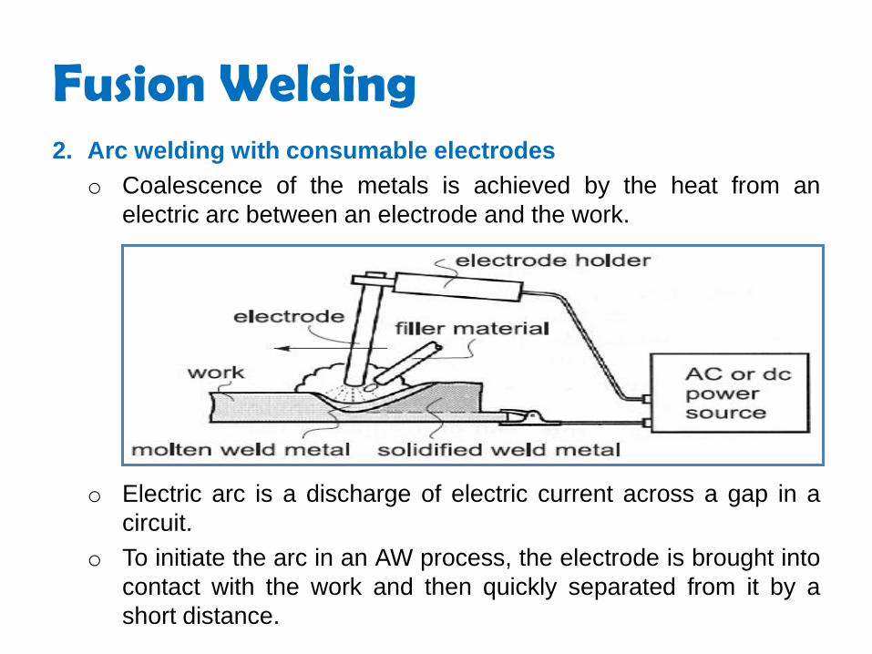
2. Arc welding with consumable electrodes
o Coalescence of the metals is achieved by the heat from an
electric arc between an electrode and the work.
o Electric arc is a discharge of electric current across a gap in a
circuit.
o To initiate the arc in an AW process, the electrode is brought into
contact with the work and then quickly separated from it by a
short distance.
Fusion Welding

o The electric energy from the arc thus formed produces temperatures
of 5000oC or higher, sufficiently hot to melt any metal.
o A pool of molten metal, consisting of base metal(s) and filler metal (if
one is used), is formed near the tip of the electrode. In most arc
welding processes, filler metal is added during the operation to
increase the volume and strength of the weld joint.
o As the electrode is moved along the joint, the molten weld pool
solidifies in its wake.
o Movement of the electrode relative to the work is accomplished by
either a human welder (manual welding) or by mechanical means
(machine welding, automatic welding, or robotic welding).
o Manual - quality of the weld joint is very dependent on the skill and
experience of the human welder.
o The weld quality is much better in the machine, automatic and
robotic welding.
Fusion Welding

Electrodes are classified as:
1. Consumable - melts continuously in the process of arc welding thus
providing the required filler material
2. Non-consumable - filler material must be supplied separately.
Fusion Welding

Shielded Metal Arc Welding • Uses a consumable electrode consisting of a filler metal rod coated
with chemicals that provide flux and shielding.
• The coated welding is typically 200 to 450 mm long and 1.5 to 9.5
mm in diameter. The heat of the welding process melts the coating
to provide a protective atmosphere and slag for the welding
operation.
• Shielded metal arc welding is usually performed manually. Common
applications include construction, pipelines, machinery structures,
shipbuilding and repair work.
• During operation the bare metal end of the welding stick is clamped
in an electrode holder connected to the power source.
• The holder has an insulated handle so that it can be held and
manipulated by a human welder.
• Currents typically used in SMAW range between 30 and 300 A at
voltages from I5 to 45 V depending on the metals being welded,
electrode type and length and depth of weld penetration required.
• It is preferred over oxy-fuel welding for thicker sections above 5 mm
because of its higher power density.
• The equipment is portable and low cost, making SMAW highly
versatile and probably the most widely used of the AW welding
processes.
• Base metals include steels, stainless steels, cast irons, and certain
nonferrous alloys.
Shielded Metal Arc Welding

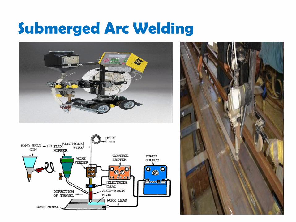
Submerged Arc Weldingo Uses a continuous, consumable bare wire electrode.
o The arc shielding is provided by a cover of granular flux. The
electrode wire is fed automatically from a coil into the arc. The flux is
introduced into the joint slightly ahead of the weld arc by gravity
from a hopper.
o Blanket of granular flux completely submerges the arc welding
operation, preventing sparks, spatter, and radiation that are so
hazardous in other arc welding processes.
Submerged Arc Welding

o Flux closest to the arc is melted, mixing with the molten weld metal
to remove impurities and then solidifying on top of the weld joint to
form a glasslike slag.
o The slag and infused flux granules on top provide good protection
from the atmosphere and good thermal insulation for the weld area
and lead to a high-quality weld joint.
o The infused flux remaining after welding can be recovered and
reused. The solid slag covering the weld must be chipped away
usually by manual means.
o This process is widely used for automated for large-diameter pipes,
tanks, and pressure vessels.
o Because of the gravity feed of the granular flux, the parts must
always be in a horizontal orientation.
Submerged Arc Welding
3) Arc welding with non-consumable electrodes
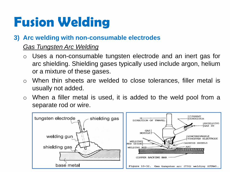
Gas Tungsten Arc Welding
o Uses a non-consumable tungsten electrode and an inert gas for
arc shielding. Shielding gases typically used include argon, helium
or a mixture of these gases.
o When thin sheets are welded to close tolerances, filler metal is
usually not added.
o When a filler metal is used, it is added to the weld pool from a
separate rod or wire.
Fusion Welding

o Applicable to nearly all metals in a wide range of stock thickness.
o It can also be used for joining various combinations of dissimilar
metals. Its most common applications are for aluminium and
stainless steel.
o The process can be performed manually or by machine and
automated methods for all joint types.
o Advantages include high-quality welds, no weld spatter because no
filler metal is transferred across the arc, and little or no post-weld
cleaning because no flux is used.
Fusion Welding

Plasma Arc Welding
o Special form of gas tungsten arc welding in which a plasma arc is directed
at the weld area.
o The tungsten electrode is contained in a specially designed nozzle that
focuses a high-velocity stream of inert gas (for example, argon or argon-
hydrogen mixtures, and helium) into the region of the arc to produce a high-
velocity plasma jet of small diameter and very high-energy density.
Temperatures reach 30,000oC or greater, hot enough to melt any known
metal.
o A substitute for GTAW in applications such as automobile subassemblies,
metal cabinets, door and window frames, and home appliances.
o Can be used to weld almost any metal, including tungsten.
Fusion Welding
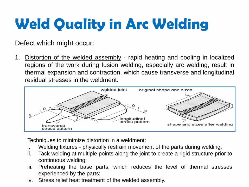
Weld Quality in Arc WeldingDefect which might occur:
1. Distortion of the welded assembly - rapid heating and cooling in localized
regions of the work during fusion welding, especially arc welding, result in
thermal expansion and contraction, which cause transverse and longitudinal
residual stresses in the weldment.
Techniques to minimize distortion in a weldment:
i. Welding fixtures - physically restrain movement of the parts during welding;
ii. Tack welding at multiple points along the joint to create a rigid structure prior to
continuous welding;
iii. Preheating the base parts, which reduces the level of thermal stresses
experienced by the parts;
iv. Stress relief heat treatment of the welded assembly.

2. Cracks - Fracture-type interruptions either in the weld or in the base
metal adjacent to the weld. It constitutes a discontinuity in the metal
that causes significant reduction in the strength of the weldment and
must be repaired.
3. Cavities - include various porosity (small voids in the weld metal
formed by gases entrapped during solidification) and shrinkage
voids (cavities formed by shrinkage during solidification).
4. Solid inclusions - any non-metallic solid material entrapped in the
weld metal.
5. Incomplete fusion - fusion does not occur throughout the entire
cross section of the joint.
Weld Quality in Arc Welding

4. Resistance Welding
• Utilizes a combination of heat and pressure to accomplish
coalescence. The heat required is generated by electrical
resistance to current flow at the interface of two parts to be
welded.
Resistance Spot Welding
• Fusion of the base metal is achieved at one location by opposing
electrodes. The cycle in a spot welding operation consists of the
steps depicted in the figure:
Fusion Welding

o Widely used in mass production of automobiles, appliances, metal
furniture, and other products made of sheet metal of thickness 3 mm
or less.
o For large, heavy work, portable spot welding guns are available in
various sizes and configurations. They are widely used in
automobile final assembly plants to spot-weld the sheet-metal car
bodies.
o Human workers operate some of these guns, but industrial robots
have become the preferred technology.
Fusion Welding

Resistance Seam Welding
o The electrodes are two rotating wheels as shown in the figure:
o A series of overlapping spot welds is made along the lap joint. The
process is capable of producing airtight joints, and its industrial
applications include the production of gasoline tanks and various
others fabricated sheet-metal containers
Fusion Welding

o The spacing between the weld nuggets depends on themotion of the electrode wheels relative to the application ofthe weld current.
o Conventional seam welding - wheel is rotated continuously ata constant velocity, and current is turned on at timing intervalsconsistent with the desired spacing between spot welds alongthe seam so that overlapping weld spots are produced.
o Roll spot welding - if the frequency of current switching isreduced sufficiently there will be spacing between the weldspots.
o Continuous resistance seam welding - welding currentremains on at a constant level so that a truly continuous seamis produced. These variations are depicted in the figure:
Fusion Welding


Solid State Welding Two parts are jointed together under pressure or a combination of
pressure and heat.
If heat is applied, the contact temperature is below the melting point
of the base metal.
There are a few types:
1. Forge Welding
o Components to be joined are heated to hot working
temperatures and then forged together by hammer or other
means.
o Considerable skill was required by the craftsmen who practiced it
to achieve a good weld. It is of minor commercial importance
today.

2. Cold Roll Welding
o Accomplished by applying high pressure by means of rolls
between clean contacting surfaces at room temperature.
o Metals to be welded must be very ductile and free of work
hardening. Contact surfaces must be exceptionally clean.
o Metals such as soft aluminium, copper, gold and silver can be
readily cold-welded.
o For small parts, the forces may be applied by simple hand
operated tools. For heavier work, powered presses are required
to exert the necessary force.
o Applications include producing sandwich strips for coins.
Solid State Welding

3. Friction Welding
o Coalescence is achieved by frictional heat combined with
pressure.
o Heat is generated by the friction between the two components
surfaces, usually by rotation of one part relative to the other.
Then the parts are driven toward each other with sufficient force
to form a metallurgical bond.
Solid State Welding

o The axial compression force upsets the parts, and the material
displaced produces a flash. The flash must be subsequently
trimmed to provide a smooth surface in the weld region.
o No filler metal, flux, or shielding gases are required.
o With its short cycle times, the process is suitable for mass
production. It is applied in the welding of various shafts and tubular
parts of similar or dissimilar metals.
Solid State Welding

• It’s a low temperature of joining process. It’s performed at
temperatures above 840ºF and it generally affords strengths
comparable to those of the metal which it joins.
• Brazing can be classified as:
i. Torch brazing
ii. Dip brazing
iii. Furnace brazing
iv. Induction brazing
Brazing

Advantages
• Dissimilar metals which cannot be welded can be joined by brazing
• Very thin metals can be joined
• Metals with different thickness can be joined easily
• In brazing thermal stresses are not produced in the work piece.Hence there is no distortion
• Using this process, carbides tips are brazed on the steel toolholders
Disadvantages
• Brazed joints have lesser strength compared to welding
• Joint preparation cost is more
• Can be used for thin sheet metal sections
Brazing

Soldering • It is a low temperature joining process. It is performed at
temperatures below 840ºF for joining.
• Soldering is used for:
• Sealing, as in automotive radiators or tin cans
• Electrical connections
• Joining thermally sensitive components
• Joining dissimilar metals

Adhesive Bonding (Gluing)Basic Properties - to function effectively as an adhesive, a material
must be capable of two things:
i. Wetting the surface to generate intimate contact between theadhesive and substrate surfaces
ii. Hardening to generate a cohesively strong solid (curing by chemical,solvent loss or cooling)
There are thousands of different adhesives; they might be divided into
three major types:
1. Thermoplastic adhesives
2. Thermosetting adhesives
3. Rubber-resin blends

Adhesive Bonding (Gluing)

Thermoplastic Adhesives • They are fusible, soluble and poor heat and creep resistant. They
are normally used for low load assemblies under gentle service
conditions
Thermosetting Adhesives • They are essentially infusible, insoluble and show good creep
resistance. They are used for high load assemblies and severe
service conditions such as heat, cold, radiation etc.

Rubber-resin Blends • As the name indicates, rubbers and resins mixed together in order
to obtain combinations of desired properties.

Anaerobics• Anaerobic adhesives cure when in contact with metal, and the air is
excluded, e.g. when a bolt is home in a thread. They are often
known as "locking compounds", being used to secure, seal and
retain turned, threaded, or similarly close fitting parts. They are
based on synthetic acrylic resins.

Acrylic Based Adhesives• Advantages: They are cross-linkable and deliver good resistance to
varying temperature ranges, chemicals, ultraviolet light and
oxidation. They are very color stable and can be easily removed and
reinstalled in the application if done incorrectly.
• Disadvantages: Generally, acrylic based PSAs have poor adhesion
to polyolefins. The initial bond or tack strength of acrylic adhesive is
low.

Cyanoacrylates • Cyanoacrylate adhesives cure through reaction with moisture held
on the surface to be bonded. They need close fitting joints and
usually solidify in seconds.
• Cyanoacrylate are suited to small plastic parts and to rubber. They
are a special type of acrylic resin.

Toughened Acrylics • Toughened acrylics are fast curing and offer high strength and
toughness. Both one and two part systems are available.
• In two part systems, no mixing is required because the adhesive is
applied to one substrate, the activator to the second substrate and
the substrates joined.
• They tolerate minimal surface preparation and bond well to a wide
range of materials.

Epoxy • Epoxy adhesives consist of an epoxy resin plus a hardener. They
allow great versatility in formulation since there are many resins and
many different hardeners.
• Epoxy adhesives can used to join most materials. These materials
have good strength, do not produce volatiles during curing and have
low shrinkage.

Polyurethanes• Polyurethane adhesives are chemically reactive formulations that
may be one or two part systems and are usually fast curing. They
provide strong resilient joints which are impact resistant and have
better low temperature strength than any other adhesive.
Polyurethanes are useful for bonding glass fibre reinforced plastics
(GRP).

Silicones • Silicones are not very strong adhesives, but are known for their
flexibility and high temperature resistance. They are often used as
bath and shower sealants. Their adhesion to surfaces is only fair but
like their flexibility, their durability is excellent.

Phenolics • Phenolics were the first adhesives for metals and have a long
history of successful use for joining metal to metal and metal to
wood. They require heat and pressure for the curing process.

Polyimide • Polyimide adhesives are based on synthetic organic chains. They
are available as liquids or films, but are expensive and difficult to
handle.
• Polyimide are superior to most other adhesive types with regard to
long term strength retention at elevated temperatures.

Applications• Protective Films: Acrylic/Polyester, Silicone/Polyester
• Heat Activated Dry Films Plating Tapes: Crosslinked Silicone
• Splicing Tapes
• Building Components
• Furniture
• Footwear
• Doors and Millwork
• Masking tapes
• Aerospace Speciality Products