scattering meter - comm-tec.com · return policy for instruments with anti-fouling treatment ......
TRANSCRIPT

Scattering Meter BB9
User’s Guide
The user’s guide is an evolving document. If you find sections that are unclear, or missing information, please let us know. Please check our website periodically for updates.
WET Labs, Inc. P.O. Box 518 Philomath, OR 97370 541-929-5650 fax: 541-929-5277 www.wetlabs.com


Attention!
Return Policy for Instruments with Anti-fouling Treatment
WET Labs cannot accept instruments for servicing or repair that are treated with anti-fouling compound(s). This includes but is not limited to tri-butyl tin (TBT), marine anti-fouling paint, ablative coatings, etc. Please ensure any anti-fouling treatment has been removed prior to returning instruments to WET Labs for service or repair.


ECO Sensor Warranty This unit is guaranteed against defects in materials and workmanship for one year from the original date of purchase. Warranty is void if the factory determines the unit was subjected to abuse or neglect beyond the normal wear and tear of field deployment, or in the event the pressure housing has been opened by the customer. To return the instrument, contact WET Labs for a Return Merchandise Authorization (RMA) and ship in the original container. WET Labs is not responsible for damage to instruments during the return shipment to the factory. WET Labs will supply all replacement parts and labor and pay for return via 3rd day air shipping in honoring this warranty.
Shipping Requirements 1. Please retain the original Pelican® shipping case. It meets stringent shipping and insurance
requirements, and protects your meter.
2. Service and repair work cannot be guaranteed unless the meter is shipped in its original case.
3. Clearly mark the RMA number on the outside of your case and on all packing lists.
Return instruments using 3rd day air shipping or better: do not ship via ground.


Table of Contents
1. Overview ...................................................................................... 1
1.1 Specifications..................................................................................................... 1 1.2 Connector........................................................................................................... 2 1.3 Delivered Items.................................................................................................. 2
2. Theory of Operation ..................................................................... 3
3. Operation .................................................................................. 5 3.1 Initial Checkout.................................................................................................. 5 3.2 Operating the Sensor for Data Output ............................................................... 5 3.3 Deployment........................................................................................................ 6 3.4 Upkeep and Maintenance................................................................................... 6
4. Data Analysis ............................................................................... 7 4.1 Data Corrections ................................................................................................ 7 4.2 Derived Parameters............................................................................................ 8
5. Testing and Calibration ................................................................ 9 5.1 Testing................................................................................................................ 9 5.2 Calibration........................................................................................................ 10
Appendix A: Output Record Definition ......................................... 11
Appendix B: BB9 Device File ....................................................... 12
BB9 User’s Guide (bb9) Revision H 11 September 2007 i


1. Overview The BB9 contains three BB3 instruments and one ECO data multiplexer (ECO Mux), all contained within a single pressure housing. Each BB3 instrument provides a backscatter measurement for three different wavelengths. The ECO Mux has four functions: 1. Switch on/off the power to the BB3 instruments. 2. Concurrently start each data sample. 3. Read the data from all three BB3s. 4. Reformat and output the data from all three BB3s in a synchronized manner.
1.1 Specifications Mechanical Diameter 5.75 in (14.6 cm) Length 12 in (30.5 cm) Weight in air 6.9 lbs (3.1 kg) Weight in water 4.1 lbs (1.8 kg) buoyant Pressure housing Acetal copolymer Electrical Connector MCBH6M Input 7–15 VDC Current, typical 300 mA @ 12 volts Sample rate 1 Hz RS-232 output 19200 baud Environmental Temperature range 0–30 deg C Depth rating 600 m Optical Wavelengths(nm) 412: 2.44 x 10⁻⁵ 595: 1.02 x 10⁻⁵ and Sensitivity 440: 2.60 x 10⁻⁵ 660: 3.79 x 10⁻⁶
488: 2.14 x 10⁻⁵ 676: 3.60 x 10⁻⁶
510: 1.81 x 10⁻⁵ 715: 3.20 x 10⁻⁶
532: 7.70 x 10⁻⁶
Range, typical ~ 0.0024–5 m-1
Linearity 99% R2
BB9 User’s Guide (bb9) Revision H 11 September 2007 1

1.2 Connector The ECO BB9 uses a six-pin bulkhead connector; the pin functions for this connector are shown in Figure 1. Table 1 summarizes pin functions for the bulkhead connectors.
Figure 1. ECO BB9 connector schematic
Table 1. Pinout summary for ECO BB9 connectors Pin (or Socket) Function
1 Ground 2 RS-232 (RX) 3 Reserved 4 V in 5 RS-232 (TX) 6 Reserved
WARNING If you are going to build or use a non-WET Labs-built cable, do not use
the wire from pin 3 or the ECO meter will be damaged. Input power of 7.5–15 VDC is applied to pin 4. The power supply current returns through the common ground pin. The input power signal has a bi-directional filter. This prevents external power supply noise from entering into ECO BB9, and also prevents internally generated noise from coupling out on to the external power supply wire. Data is sent out the serial output pin.
1.3 Delivered Items • BB9 meter • test cable (optional) • this user’s guide • ECOView user’s guide • ECOView host program and device file (on CD) • instrument-specific calibration sheet • protective covers for optics (3) • dummy plug • fluorescent sticks for bench testing
2 BB9 User’s Guide (bb9) Revision H 11 September 2007

2. Theory of Operation The Environmental Characterization Optics, or ECO scattering meter allows the user to measure scattering at nine wavelengths at 117 degrees. This angle was determined as a minimum convergence point for variations in the volume scattering function induced by suspended materials and water itself. Therefore, the signal measured by this meter is less determined by the type and size of materials in the water and more directly correlated to the concentration of the materials. The BB9 uses nine LEDs (modulated at 1 kHz) for source light. The source light enters the water volume and scattered material is detected by a detector positioned where the acceptance angle forms a 117-degree intersection with the source beam. Figure 3 shows the meter’s optical configuration. Refer to the instrument-specific calibration sheet for each BB wavelength.
Figure 2. Optical configuration of ECO scattering meter
BB9 User’s Guide (bb9) Revision H 11 September 2007 3


3. Operation The BB9 has been programmed to start sampling immediately upon power up. Note that version 1.1 of the BB9 firmware does not allow for any user control of the individual BB3 meters, which have been set for 18 over-samples per reported value. The firmware does not allow for any alteration of the default BB9 output data rate of 1 Hz.
3.1 Initial Checkout Supplied from the factory, the BB9 is configured to begin continuously sampling upon power-on. Electrical checkout is straightforward: connect the 6-socket connector on the test cable to the instrument. Light should emanate from the meter.
3.2 Operating the Sensor for Data Output Required equipment: • BB9 meter • Test cable (optional equipment) • BB9 device file, preferably stored on host computer • Host computer with WET Labs ECOView software (or terminal program) installed.
1. Connect the 6-socket test cable connector to the instrument to provide power.
2. Connect the DB-9 connector to the host computer.
WARNING! Always use a regulated power supply to provide 7–15 volts of power to sensor if not using
the 9V battery provided with the test cable: power spikes may damage the meter. 3. Remove the protective optics covers.
4. Start ECOView. Select the appropriate COM Port and device file. Supply power to the
meter. Output will appear in the Raw Data window:
WETA_BB90132 21 1 442 1562 136 1432 98 1360 77 1455 79 1595 61 1819 74 1220 44 1448 53 1359 47 103d WETA_BB90132 21 1 443 1562 132 1432 94 1360 72 1455 72 1595 62 1819 75 1220 41 1448 53 1359 48 102a WETA_BB90132 21 1 444 1562 138 1432 95 1360 78 1455 82 1595 58 1819 71 1220 50 1448 55 1359 50 1035 WETA_BB90132 21 1 445 1562 142 1432 94 1360 74 1455 76 1595 63 1819 70 1220 49 1448 53 1359 49 1038
The BB9 output consists of 23 columns. Column 1: meter ID Column 2: # of columns to follow (21) Column 3: firmware version Column 4: counter Columns 5–23: reference and signal for each of the nine wavelengths.
BB9 User’s Guide (bb9) Revision H 11 September 2007 5

3.3 Deployment Once the operation of the BB9 is verified, the unit is ready for submersion and subsequent measurements. Some consideration should be given to the package orientation. Do not face the sensor directly into the sun or other bright lights. For best output signal integrity, locate the instrument away from significant EMI sources.
Caution The BB9 should be mounted so that the LED source will not “see” any part of a cage or
deployment hardware. This will affect the sensor’s output.
Other than these basic considerations, one only needs to make sure that the unit is securely mounted to whatever lowering frame is used and that the mounting brackets are not damaging the unit casing. The instrument can be used in a moored or profiling mode.
3.4 Upkeep and Maintenance We highly recommend that ECO meters be returned to the factory annually for cleaning, calibration and standard maintenance. Contact WET Labs or visit our website for details on returning meters and shipping.
The BB9 maintenance can be easily overlooked; however, it is a precision instrument and does require a minimum of routine upkeep. After each cast or exposure of the instrument to natural water, flush the instrument with clean fresh water, paying careful attention to the sensor faces. Use soapy water to cut any grease or oil accumulation. Gently wipe clean with a soft cloth and place the protective covers on the optics: the sensor faces are composed of ABS plastic and optical epoxy and can easily be damaged or scratched.
WARNING! Do not use acetone or other solvents to clean the sensor.
At the end of an experiment, the instrument should be rinsed thoroughly, air-dried and stored in a cool, dry place.
6 BB9 User’s Guide (bb9) Revision H 11 September 2007

4. Data Analysis Raw data from the BB9 is output as counts from the sensor, ranging from 0 to 4120. After the sensor is calibrated (i.e., subtracting the dark offset and multiplying by scaling factor—see Section 5), this data is now in the meaningful form of volume scattering coefficients, β(θ,λ) with units of m-1 sr-1, where θ is angle and λ is wavelength. The host program will automatically perform the necessary calculations.
4.1 Data Corrections Attenuation coupling—For the population of photons scattered within the remote sample volume in front of the sensor face, there is attenuation along the path from the light source to the sample volume to the detector. This results in the scattering measurements being underestimates of the true volume scattering in the hydrosol. Corrected volume scattering coefficients can be obtained by accounting for the effect of attenuation along an average pathlength. This average pathlength was numerically solved in the weighting function determinations developed by Dr. Ron Zaneveld that are used in the calibration procedures. Since the calibration of the BB9 uses microspherical scatterers, the component of attenuation that can be attributed to scattering is incorporated into the scaling factor, i.e., the calibration itself. Thus, only absorption of the incident beam needs to be included in the correction. The dependence on absorption, a, is determined as follows, where the measured scattering function at a given value of a, beta_meas(angle, a), is corrected to the value for a = 0 m-1, beta_corr(117°, a=0): beta_corr(117°, a=0) = beta_meas(117°, a) exp(0.0391a) Absorption can be measured with an ac-9 device. For each ECO-BB3 wavelength, the matching absorption coefficient must be used from the ac-9. Because the ECO-BB3 incorporates short pathlengths and relatively small scattering volumes in its measurements, this attenuation error is typically small, about 4 percent at a = 1 m-1.
Temperature correction—Output from an LED reference detector is provided, which gives an indication of relative LED intensity during operation. Work is presently under way to incorporate this signal as an ongoing correction for measurements. Largest expected deviations in the calibration coefficients are about 10 percent in the temperature range 0–28 degrees C. Note that these errors become more pronounced for very clear waters. If the instrument is planned for use in clear water environments at the ends of this temperature range, it is recommended that a request be made for calibration data to be collected as close to the expected environmental temperature as possible.
BB9 User’s Guide (bb9) Revision H 11 September 2007 7

4.2 Derived Parameters
4.2.1 Volume Scattering of Particles The corrected volume scattering of particles, β(117°,λ) values represent total volume scattering, i.e., scattering from particles and molecular scattering from water. To obtain the volume scattering of particles only, subtract the volume scattering of water, βw(117°,λ):
βp(117°,λ) = β(117°,λ) - βw(117°,λ) where βw(117°,λ) is obtained from the relationship (from Morel 1974):
βw(θ,λ)=1.38(λ/500nm)-4.32(1+0.3S/37)10-4 (1+cos2θ(1-δ)/(1+δ))m-1sr-1, δ=0.09 where S is salinity. For total scattering of pure water,
bw(λ) = 0.0022533 (λ/500nm) -4.23. For total scattering of seawater (35–39 ppt),
bsw(λ) = 0.0029308 (λ/500nm) -4.24. For backscattering by water, divide bw or bsw by 2. The units for the b coefficients are (10-4 m-1).
4.2.2 Backscattering Coefficients Particulate backscattering coefficients, bbp(λ) with units of m-1, can be determined through estimation from the single measurement of βp(117°,λ) using an Χ factor:
bbp = 2π Χ βp(117°) From measurements of the volume scattering function with high angular resolution in a diversity of water types, Boss and Pegau (2001) have determined Χ to be 1.1 (Boss, E., and S. Pegau, 2001. The relationship of scattering in an angle in the back direction to the backscattering coefficient, Applied Optics). This factor estimates bbp with an estimated uncertainty of 4 percent. The conversion can be used for β(117°) measurements made at any visible wavelength. To compute total backscattering coefficients, bb(λ) with units of m-1, the backscattering from pure water, bbw(λ), needs to be added to bbp(λ): (See Morel, A. Optical properties of pure water and pure sea water, in Optical Aspects of Oceanography, N. G. Jerlov and E.S. Neilsen, eds. (Academic, New York, 1974), pp. 1–24.)
bb(λ) = bbp(λ) + bbw(λ).
8 BB9 User’s Guide (bb9) Revision H 11 September 2007

5. Testing and Calibration Prior to shipment, each meter is tested and calibrated to ensure that it meets specifications.
5.1 Testing When the instrument is completely assembled, it goes through the tests below to ensure performance.
5.1.1 Dark Counts Pure, de-ionized water is used to set the “zero” level of the meter. This zero level is set for 125 counts (+/-75) on all models.
5.1.2 Pressure To ensure the integrity of the housing and seals, ECOs are subjected to a wet hyperbaric test before final testing. The testing chamber applies a water pressure of at least 50 PSI.
5.1.3 Mechanical Stability Before final testing, the ECO-BB3 meters are subjected to a mechanical stability test. This involves subjecting the unit to mild vibration and shock. Proper instrument functionality is verified afterwards.
5.1.4 Electronic Stability This value is computed by collecting a sample once every 5 seconds for twelve hours or more. After the data is collected, the standard deviation of this set is calculated and divided by the number of hours the test ran. The stability value must be less than 2.0 counts/hour.
5.1.5 Noise Noise is computed from a standard deviation over 60 samples, collected at one-second intervals for one minute. The standard deviation is calculated on the 60 samples, and the result is the published resolution on the calibration sheet. The calculated standard deviation value must be below 2 counts.
5.1.6 Voltage and Current Range Verification To verify that the ECO operates over the entire specified voltage range (7–15 V), a voltage-sweep test is performed. ECO is operated over the entire voltage range, and the current and operation is observed. The current must remain constant at approximately 300 mA over the entire voltage range.
BB9 User’s Guide (bb9) Revision H 11 September 2007 9

5.2 Calibration Each meter ships with a calibration sheet that provides instrument-specific calibration information, derived from the steps below. 1. For a given scattering centroid angle (θc), compute the weighting function W(θ,θc), by
numerical integration of sample volume elements according to the sensor geometry.
2. Determine scattering phase functions, β(θ, λ)/b(λ), for the polystyrene bead microsphere calibration particles by weighting volume scattering functions computed from Mie theory according to the known size distribution of the polystyrene bead microsphere polydispersion and normalizing to total scattering.
3. By convolving W(θ,θ c) with β(θ, λ)/b(λ), compute the normalized volume scattering
coefficient for each measurement angle, β(θ, λ)/b(λ), with units of sr –1 β(θc)/b for 2.00-micron diameter polystyrene bead microspheres.
4. Experimentally obtain raw scattering counts simultaneously with attenuation coefficients
(Cp, using an ac-9) for a concentration series of the polystyrene bead microsphere polydispersion. Absorption by the calibration particles is assumed negligible.
5. Obtain b/counts from the slope of a linear regression between Cp (equivalent to b for the
beads) and counts.
6. Multiplying the experimental b/counts by the theoretical β(θc)/b yields the calibration scaling factor, SF.
7. To obtain β(θc), subtract the dark counts from the raw counts measured, then multiply by
SF.
8. This test also provides a measure of the inherent opto-electronic noise level of the instrument. A standard deviation from the average number of counts on a 1 minute data file is taken. This is translated into the resolution of β(θc) (minimum detectable signal change) in units of m-1 sr-1.
Definitions of Terms β: phase function b: total scattering coefficient θ: angle θc: centriod angle W: weighting function λ: wavelength Cp: particulate attenuation coefficient SF: Scaling Factor m-1: per meter sr-1: per steradian
10 BB9 User’s Guide (bb9) Revision H 11 September 2007
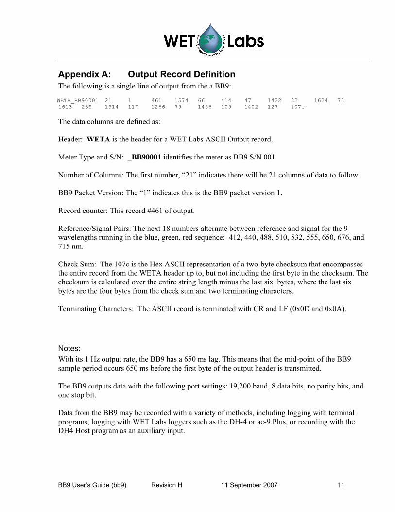
Appendix A: Output Record Definition The following is a single line of output from the a BB9:
73 1613 235 1514 117 1266 79 1456 109 1402 127 107c WETA_WETA_BB90001 21 1 461 1574 66 414 47 1422 32 1624 73 1613 235 1514 117 1266 79 1456 109 1402 127 107c
The data columns are defined as: Header: WETA is the header for a WET Labs ASCII Output record. Meter Type and S/N: _BB90001 identifies the meter as BB9 S/N 001 Number of Columns: The first number, “21” indicates there will be 21 columns of data to follow. BB9 Packet Version: The “1” indicates this is the BB9 packet version 1. Record counter: This record #461 of output. Reference/Signal Pairs: The next 18 numbers alternate between reference and signal for the 9 wavelengths running in the blue, green, red sequence: 412, 440, 488, 510, 532, 555, 650, 676, and 715 nm. Check Sum: The 107c is the Hex ASCII representation of a two-byte checksum that encompasses the entire record from the WETA header up to, but not including the first byte in the checksum. The checksum is calculated over the entire string length minus the last six bytes, where the last six bytes are the four bytes from the check sum and two terminating characters. Terminating Characters: The ASCII record is terminated with CR and LF (0x0D and 0x0A). Notes: With its 1 Hz output rate, the BB9 has a 650 ms lag. This means that the mid-point of the BB9 sample period occurs 650 ms before the first byte of the output header is transmitted. The BB9 outputs data with the following port settings: 19,200 baud, 8 data bits, no parity bits, and one stop bit. Data from the BB9 may be recorded with a variety of methods, including logging with terminal programs, logging with WET Labs loggers such as the DH-4 or ac-9 Plus, or recording with the DH4 Host program as an auxiliary input.
BB9 User’s Guide (bb9) Revision H 11 September 2007 11

Appendix B: BB9 Device File ECO BB9-132 Created on: 6/29/04 Columns=23 N/U=1 N/U=2 N/U=3 N/U=4 REF=5 Lambda=6 1.17E-05 50 412 412 REF=7 Lambda=8 4.71E-05 53 440 440 REF=9 Lambda=10 1.11E-05 55.5 488 488 REF=11 Lambda=12 8.60E-06 54 510 510 REF=13 Lambda=14 7.83E-06 78 532 532 REF=15 Lambda=16 1.88E-05 82 555 555 REF=17 Lambda=18 4.00E-06 43 650 650 REF=19 Lambda=20 3.65E-06 52 676 676 REF=21 Lambda=22 3.34E-06 49 715 715 N/U=23 N/U: Not Used
12 BB9 User’s Guide (bb9) Revision H 11 September 2007

Revision History Revision Date Revision Description Originator
1 06/30/04 Draft document D. Romanko A 4/28/05 Approved document (DCR 467) D. Romanko, W. Strubhar,
D. Whiteman B 12/8/05 Add fluorescent stick use (DCR 479) H. Van Zee C 1/13/06 Clarify warranty statement (DCR 481) A. Gellatly, S. Proctor D 4/13/06 Include record counter column in output definition
(DCR 494) D. Hankins
E 5/31/06 Add annual maintenance recommendation (DCR 498)
S. Proctor
F 9/28/06 Update specifications (DCR 507) M. Johnson G 4/30/07 Revise Operation Section to reflect ECOView as
output viewer only, no control functions (DCR 516) H. Van Zee
H 9/11/07 Update shipping requirements (DCR 531) H. Van Zee
BB9 User’s Guide (bb9) Revision H 11 September 2007