scenariobased design and simulation of mechatronic systems · scenario-based design and simulation...
TRANSCRIPT

Universität Paderborn � Fakultät EIM-ISoftware Engineering Group
Scenario-Based Design and Simulation
of Mechatronic Systems
Bachelor Thesis
Software Engineering GroupProf. Dr. W. Schäfer
Institut für InformatikFakultät für Elektrotechnik,Informatik und Mathematik
Universität Paderborn
vorgelegt vonJens Frieben
am27.03.2009
Betreuer: Joel Greenyer
Gutachter: Prof. Dr. Wilhelm SchäferProf. Dr. Heike Wehrheim
Jens FriebenMatrikelnummer: 6397644Kampstrasse 759505 Bad Sassendorf


Contents
1 Introduction 1
2 Foundations 5
2.1 Design process of mechatronic systems . . . . . . . . . . . . . . . 52.1.1 Development process . . . . . . . . . . . . . . . . . . . . . 72.1.2 Mechatronic Modelling Language . . . . . . . . . . . . . . 9
2.2 Sequence Diagrams . . . . . . . . . . . . . . . . . . . . . . . . . . 102.2.1 UML Sequence Diagram . . . . . . . . . . . . . . . . . . . 112.2.2 Live Sequence Charts LSC . . . . . . . . . . . . . . . . . . 122.2.3 Modal Sequence Diagram MSD . . . . . . . . . . . . . . . 15
2.3 S2A and AspectJ . . . . . . . . . . . . . . . . . . . . . . . . . . . 172.4 Other tools and technologies . . . . . . . . . . . . . . . . . . . . . 20
2.4.1 Activestructure-Editor . . . . . . . . . . . . . . . . . . . . 202.4.2 EMF & GMF . . . . . . . . . . . . . . . . . . . . . . . . . 202.4.3 UML2 project . . . . . . . . . . . . . . . . . . . . . . . . . 222.4.4 OCL . . . . . . . . . . . . . . . . . . . . . . . . . . . . . . 22
3 Concepts 23
3.1 Modelling . . . . . . . . . . . . . . . . . . . . . . . . . . . . . . . 233.1.1 Scenario: Railcab switches track . . . . . . . . . . . . . . . 263.1.2 Scenario: Detect Railcab - create convoy . . . . . . . . . . 323.1.3 Scenario: Enter switch . . . . . . . . . . . . . . . . . . . . 333.1.4 Scenario: Disband convoy . . . . . . . . . . . . . . . . . . 34
3.2 Tool vision . . . . . . . . . . . . . . . . . . . . . . . . . . . . . . . 353.3 Scenario-Playout . . . . . . . . . . . . . . . . . . . . . . . . . . . 36
3.3.1 Trace semantics of MSDs as a Petri net . . . . . . . . . . . 373.3.2 Initialization . . . . . . . . . . . . . . . . . . . . . . . . . . 383.3.3 Hot/Cold Violations . . . . . . . . . . . . . . . . . . . . . 393.3.4 Hot/Cold CombinedFragments . . . . . . . . . . . . . . . . 403.3.5 Asynchronous messages . . . . . . . . . . . . . . . . . . . . 403.3.6 Message selection and Playout-Strategies . . . . . . . . . . 413.3.7 Playout . . . . . . . . . . . . . . . . . . . . . . . . . . . . 42
3.4 Object Binding . . . . . . . . . . . . . . . . . . . . . . . . . . . . 433.4.1 Symbolic lifelines . . . . . . . . . . . . . . . . . . . . . . . 433.4.2 Conventional Binding . . . . . . . . . . . . . . . . . . . . . 44
III

Contents
3.4.3 Extended Binding . . . . . . . . . . . . . . . . . . . . . . . 443.4.4 Binding problems . . . . . . . . . . . . . . . . . . . . . . . 453.4.5 Assignment . . . . . . . . . . . . . . . . . . . . . . . . . . 47
3.5 Hierarchical re�nement . . . . . . . . . . . . . . . . . . . . . . . . 48
4 Implementation 51
4.1 Modal Petri nets . . . . . . . . . . . . . . . . . . . . . . . . . . . 514.1.1 Petri net elements . . . . . . . . . . . . . . . . . . . . . . . 524.1.2 Conversion . . . . . . . . . . . . . . . . . . . . . . . . . . . 53
4.2 Simulator components . . . . . . . . . . . . . . . . . . . . . . . . 56
5 Conclusions and Future Work 59
A Scenario diagrams 63
List of Figures 69
Bibliography 71
IV
1 Introduction
As part of the Collaborative Research Center 614 (CRC 614) 'Self-OptimizingConcepts and Structures in Mechanical Engineering' 1, new methods and lan-guages are developed for the design of mechatronic systems. A characteristic ofthese systems is that multiple engineering domains are involved in their devel-opment. These are generally mechanical-, controlling-, electrical-, and softwareengineering. Advanced mechatronic systems consists of software-intensive, inter-acting components, which makes the development of these systems even morechallenging.
Based on existing development guidelines like VDI 2206 [22], the CRC's new de-velopment concepts introduce methods and languages to cope with these complexsystems. At the beginning of the design process, all domains work together onthe conceptual design. The resulting design document of this combined e�orts iscalled the principle solution, and is created in four phases. One of these phasesis the 'Conceptual design on system level '. Here, the scenarios that are identi�edin a previous phase, are used to specify function hierarchy, create the systemsstructure, and to model its behavior. If the principle solution is approved, thedomains begin their own, domain speci�c development independently.
The techniques currently used in the CRC are not yet su�cient, since they can-not be formally analyzed. The formal analysis of system behavior is important inorder to detect errors early in the development stages. If errors remain undiscov-ered, the costs to correct them later in the development are signi�cantly higher.If they are not even identi�ed and solved in later development phases, this alsoa�ects the safety and reliability of the mechatronic system.
Therefore new ways to formally specify and analyze the behavior are required.One analysis method, which is also the focus of this thesis, is the simulation ofthe mechatronic systems behavior. Such an analysis allows the developer to �ndinconsistencies and errors right in the conceptual design phase.
This thesis introduces concepts and methods to specify and simulate behaviorof mechatronic systems. I present a way to model the behavior by using ModalSequence Diagrams (MSD) and a play-out engine I developed to simulate the sys-
1Collaborative Research Center 614 � www.sfb614.de
1
1 Introduction
tem afterwards. The decision to use sequence diagrams is based on two reasons.First, the design is driven by application scenarios and second are requirementsoften given in the form of sequences of interactions between environment andsystem components. A play-out is the monitoring and execution of previouslymodeled behavior diagrams. Modal Sequence Diagrams are used for this mod-elling, because they allow the distinction between possible behavior and necessarybehavior. MSDs are a form of Live Sequence Charts that was developed in orderto formalize the semantics of assert and negate in UML [12]. They allow thedeveloper to model certain interactions between system and environment compo-nents that may or must occur.My solution is similar to the play-out engine developed by Harel and Maoz[13, 11, 10]. They use the Modal Sequence Diagrams to specify the behaviorof Java-based applications. These MSDs are then compiled into an applicationspeci�c logic which is used to control the simulation. I denote this compiler andplay-out the S2A approach.
Like Harel and Maoz, I propose MSDs to model the behavior in the conceptualdesign of mechatronic systems. Based on an example I show how the scenario-based behavior speci�cation for a mechatronic system can be realized.Since the Railcab case study is often used in the CRC, this was the �rst choice foran example. The Railcab system is a novel transportation system that is currentlydeveloped at the University of Paderborn. In the future, they shall autonomouslytransport passengers and goods. Furthermore, they autonomously make certaindecisions during their operation, for example to form convoys with other Railcabsor to optimize the comfort level for passengers. The Railcab-system is a chal-lenging example with many networked systems and components/subcomponentson di�erent hierarchies, making it an ideal basis for an example.
During the course of elaborating the concepts for playing-out the MSDs, someproblems were identi�ed that could not be resolved in the scope of this thesis.Concepts for the desired use case for modeling and simulating in hierarchicalcomponent structures are investigated, but could not be implemented in time.Also the assignment of values and references is left open for implementation. Thisrestricts the current available simulation procedure drastically, since no changesto the model can be made. Discovered problems with play-out when dealing withsystems with dynamic structure could be solved and integrated into the currentimplementation.
The second chapter Foundations introduces the development process for mecha-tronic systems in more detail. A short overview to the Railcab and its modulesand components is given. Following this are the descriptions of interaction dia-
2

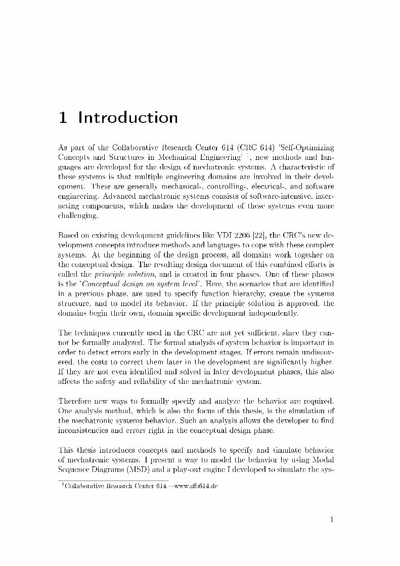
Figure 1.1: Two Railcabs autonomously formed a convoy to optimize their energymanagement.
grams that are used in this thesis. I introduce Live Sequence Charts (LSC) andgive a short description of a LSC Play-out - a procedure to simulate modeledbehavior. An extended version of the LSC, the Modal Sequence Diagrams, thatare used in the S2A play-out [10] and my approach. Therefore I explain themin more detail before I proceed to the S2A approach, on which my simulationengine is based.A main topic of this thesis is how the behavior of mechatronic systems can bemodeled in a scenario-based way. Therefore, I will start the third chapter Con-cepts with the example and its scenarios. The behavior of scenario each is modeledwith MSDs. With these behavior diagrams at hand, the vision of a tool for mod-elling and simulation is sketched. Driven by this vision I introduce the conceptsfor the play-out I developed. Problems that I identi�ed during the modellingphase are the focus of the last sections of the concepts chapter. To complete thisthesis, the Implementation chapter show some details about the representationof MSDs as Petri nets and a conclusion give a resume and an outlook on revealedor still open questions.
3

1 Introduction
4
2 Foundations
This chapter gives an overview of the terminology and some basic technologiesthat are used within this thesis. First I explain what mechatronic systems are,the problems in design of these systems, and the new development approach.Afterwards the basics of sequence diagrams and the two derivative speci�cations'Live Sequence Charts' and 'Modal Sequence Charts' are explained. Based onthese prerequisites, I introduce the S2A compiler which makes use of these dia-grams. AspectJ, an aspect oriented extension to Java, is a vital part of the S2Aplay-out. Therefore I give a short overview of this topic. To conclude the foun-dations chapter the Partialmodel-Editor and its dependencies Eclipse ModellingFramework (EMF), the UML2 project, Object Constraint Language (OCL) areexplained in detail.
2.1 Design process of mechatronic systems
A characteristic of mechatronic systems is that several engineering domains are in-volved in their development. These domains are usually mechanical engineering,electrical engineering, control engineering, and software engineering. So everysystem that combines mechanical parts with electrical elements and informationprocessing is a mechatronic system. Today these systems can be found every-where in the form modern washing machines, cars, and airplanes.
Mechatronic systems usually consist of multiple reusable modules called Mecha-tronic Function Module (MFM). These MFMs are designed, created and testedindependently from the other components. If a MFM acts autonomously - itreacts and acts self-determinedly - it is called an AMS, in short AutonomousMechatronic System. If two or more AMSs are connected via any kind of com-munication, this network is called DMS, an acronym for Distributed MechatronicSystem. For further information on these de�nitions, see [6, 23].
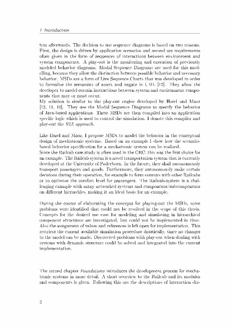
Figure 2.1 shows an overview of these systems in a real world example. The Rail-cab1 [15], that is also the basis for most examples in this thesis, incorporates allthree types MFM, AMS and DMS. The Railcab system is a novel transportationsystem that is currently developed at the University of Paderborn. Part of this
1Neue Bahntechnik Paderborn http://www-nbp.uni-paderborn.de/
5

2 Foundations
system are the so called Railcabs - autonomous vehicles that are able to makedecisions on their own. In this hierarchy the MFMs modules like Drive-and-Braking, Energy-supply, and Track-guidance build the foundation of an AMS.These parts give the Railcab the ability of self-optimization with inherent in-telligence. It can independently and �exible change operating conditions. Oneadvantage of the Railcab system is the ability to create a convoy. For exampleare the Railcabs able to detect each other and exchange information about direc-tion, current speed and other important data needed to form a convoy. Based inthese information, the Railcabs decide on their own whether to create a convoy ornot. This interaction and communication is exactly the de�nition of DMS. Somemore details about the Railcabs possible decisions, their behavior, and internalcomponents will be given in the concepts chapter 3.
Figure 2.1: Hierarchy of MFM, AMS, and DMS
Accompanying the immense possibilities are also the problems in the design ofthese systems. The complexity in the development of these system can be muchhigher than in a single domain. Interaction and self-optimizing mechatronic sys-tems result in many new problems that have to be solved. These can range fromshared ressources and possible con�icts when accessing them, to basic commu-nication issues. A very important source of errors and design issues lies in theseparated design processes of the involved domains. An explanation of these
6
2.1 Design process of mechatronic systems
problems and how to cope them is given in the following section.
2.1.1 Development process
The design of self-optimizing mechatronic systems introduces some new chal-lenges for the development process. Many aspects have to be speci�ed includingnot only structure, but also goals for self-optimization, behavior of this intelligentsystems, situations/scenarios the system must handle and many more. Thereforeguidelines like 'VDI 2206' [22] are not su�cient any more.
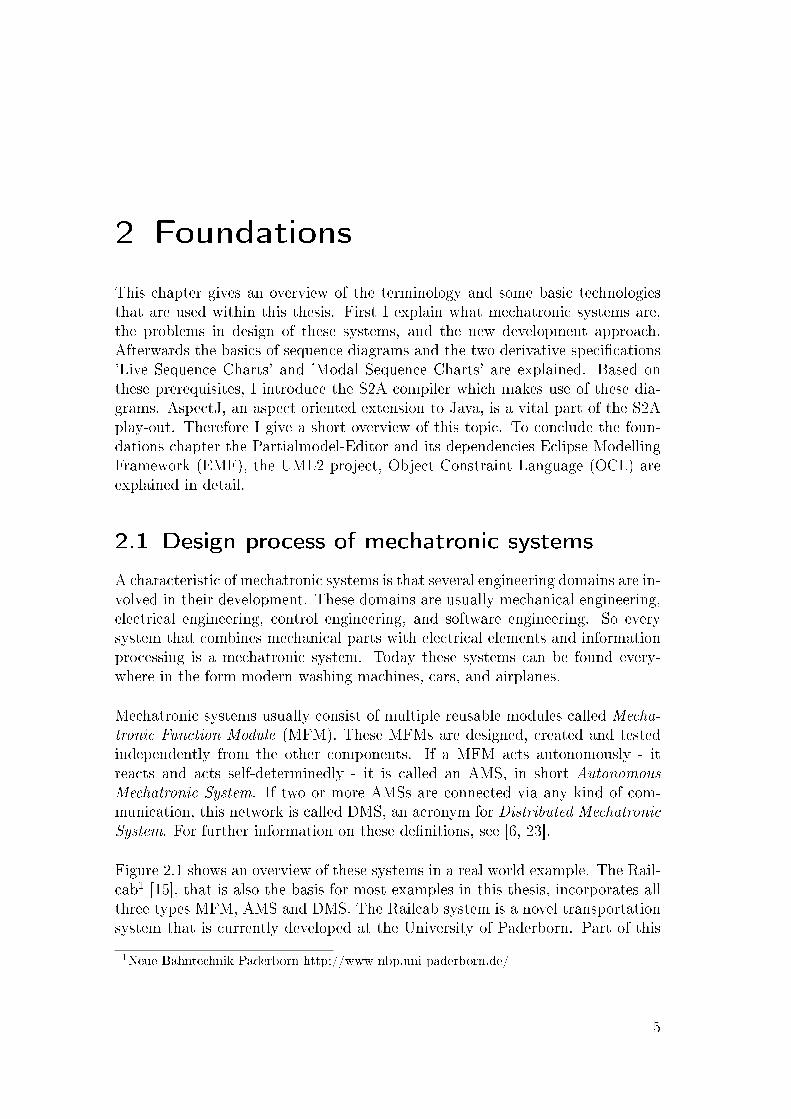
For the special purpose of designing mechatronic systems, a new developmentprocess is being developed [8, 9, 7]. It is an advancement to the normal mechan-ical development process and incorporating the other three domains software-,electrical-, and control engineering. Figure 2.2 shows the 'VDI Guideline 2206 ',a directive for the design methodology for mechatronic systems. On the left sideof this 'V' is the systemdesign. This is the phase where all domains work togetheron the single, cross-domain design document, the principle solution.The conception stage is partitioned into four phases (see illustration 2.3) - 'Task
Figure 2.2: VDI-Guideline 2206 'Design methodology for mechatronic systems'.
Analysis ', 'Conceptual design on system level ', 'Conceptual design on modulelevel ', and 'Concept Integration' - each with their own outcoming design docu-ments.
7

2 Foundations
In the Task Analysis phase, the desired functions, requirements, and tasks of thefuture system are investigated. In addition to this, scenarios are collected whichare used in the second phase. The Task Analysis phase is also used to specify theenvironment of the mechatronic system. The second phase called 'Conceptualdesign on system level' is of most interest for this thesis. As shown in �gure 2.3this phase consists of three steps. In the �rst step the initial function hierarchyis speci�ed. It is a hierarchical breakdown of the application functions, coveringconventional and self-optimizing functionality. Step two uses the scenarios iden-ti�ed in phase one and represents the application-scenario driven developmentpart of this design process.In each scenario, the necessary functions are determined. Previously de�ned
Figure 2.3: The four phases of the conception stage and their resulting documents.
functions can be reused and new ones are added to or update the function hier-archy. This information is combined with additional information like for examplestructure, internal behavior or shape into elements. The reused elements arecalled Solution elements and new created elements are denoted as System ele-ments. The resulting structure of system and solution elements can be modeledwith the Mechatronic Modelling Language and results in the active structure.Also speci�ed in each scenario is the systems behavior. This includes activities,states and transitions of the system as well as the communication and cooperationwith other systems or subsystems. The analysis of the behavior gives a �rst ideaof the internal optimization processes, so that �nally the 'System of Objectives 'can be de�ned. Last step of the 'Conceptual design on system level ' phase is theintegration of all scenarios, resulting in the system level principle solution.
If the phases three and four have been completed, the �nal principle solutiondocument is available. As soon as the �nal version of the principle solution is
8

2.1 Design process of mechatronic systems
approved and the conception phase has ended, the domains start their own, moredetailed design independently from the other domains. Is their development com-plete, the di�erent designs are merged again during the systemintegration phase,creating the complete speci�cation for the �nal product.
2.1.2 Mechatronic Modelling Language
The principle solution consists of a set of models, which allow di�erent views onthe system under development. In the context of the CRC 614, they are oftenreferred to as 'the partial models', however, in the following I will refer to thislanguage as the Mechatronic Modeling Language (MML). This modelling lan-guage is currently developed by the CRC and captures the relationships betweenthese models. Figure 2.4 shows an overview of the eight models: Requirements,Environment, System of Objectives, (application) Scenarios, Functions, activestructure, Shape, and Behavior.
Figure 2.4: Principle solution overview showing the seven connected partial mod-els
9
2 Foundations
• Requirements: This is the representation of the requirements, like valuesfor height, width, maximum speed and so on.
• Environment: This model describes the environment of the system and itsintegration into the environment. In�uences, possible interference factorsand interactions with the system are identi�ed here.
• System of Objectives: It is the representation of objectives and theirrelations. These could be for example objectives like driving comfort,traveltime, deterioration, reliability and their relation to each other.
• Scenarios: Application scenarios describe small parts of the functionalityof the system that is being developed. They specify how the system shouldbehave in a particular state and situation.
• Functions: It is a hierarchical breakdown of application functions and usedto de�ne the functionality of the system. They can be conventional or forself-optimization purposes.
• Activestructure: Here are the selected system elements, their propertiesand relationships illustrated. The aim is to describe the basic structure ofthe self-optimizing system, including all anticipated system con�gurations.
• Shape: This model includes data/values about shape, location, alignment,sizes of surfaces and many more. This model is often accompanied by CADmodels.
• Behavior: This group includes di�erent types of behavior. Basically, thesystemstates with the associated process �ow and the state transitions withthe underlying adaption processes is modeled here. The adaption or adjust-ment processes describe the actual implementation of the self-optimization.Behavior represents a group, due to the fact that there exist many types ofbehavior. These could be for example be the behavior for a logic circuit,dynamic behavior of multi-body systems, electromagnetic compatibility orinteraction behavior.
For this thesis are the three partialmodels Activestructure, Behavior and Sce-narios of importance. The Active Structure model de�nes all objects that areneeded for modelling the behavior. Behavior in combination with the Scenariosspecify how the system will react in certain situations.
2.2 Sequence Diagrams
This subsection gives a short overview of the message sequence diagrams thatare used in this thesis. Section 2.2.1 introduces the basic concepts, elements
10
2.2 Sequence Diagrams
and constructs of message sequence diagrams. Based on this, the Life SequenceCharts (LSC) are explained. The last kind of sequence diagram described inthis foundations chapter is the Modal Sequence Diagram (MSD), which is anextension to LSCs.Please note that in some diagrams the arrows representing the messages havealso a dot at the beginning. This dot denotes the send event of a message.
2.2.1 UML Sequence Diagram
A sequence diagram is an interaction diagram in UML, that shows how objectscommunicate with each other. This is speci�ed with an ordered sequence of mes-sages send between them. The current version of the OMG2 speci�cation is UML2.1 [19].Sequence diagrams are used to model the communication between objects. Thepossible �ow of control throughout the processes are described in two dimen-sions: horizontal are the involved active objects and vertical the ordering of time.Lifelines represent these involved active objects, and come in two kinds. Actuallifelines map a speci�c object to a lifeline and symbolic lifelines are placeholderfor objects of the given type.Messages are send from one lifeline to another and are represented by horizontalarrows. The only invariant is that sending of a message must occur before the re-ception of that message. The sending and receiving of a message are called event.In the sequence diagrams, we specify the occurrences of an event on a lifeline.An event is a point in time and has no duration. A trace is a sequence of eventsordered in time and describes the history of message-exchange corresponding toa system run. Messages that have no duration between sending and receivingevent are called synchronous. The opposite type, asynchronous messages, arenot instantaneously transmitted.A gate a special kind of an event that is used to model the passing of informa-tion between a sequence diagram and its context. They are �xed on the diagramborders and can have incoming or outgoing messages.Also included in the UML 2.0 speci�cation are constructs like alternatives, loops,parallels, asserts, and more. The description of these elements is postponed tothe Modal Sequence Diagram section.
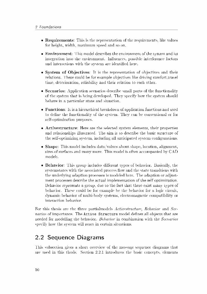
Figure 2.5 shows a simple UML sequence diagram with three lifelines representingtwo Railcabs and a TrackControl. Message getRCsOnTrack is the �rst mes-sage that is being send from rc1 to the tc TrackControl, followed by the sendingof notifyRailcab to rc2. After this message is received, the second Railcabsends the registerAtRailcab to rc1. Activation boxes, or method-call boxes,are the opaque rectangles drawn on top of lifelines to represent that processes
2Object Management Group � www.omg.org
11
2 Foundations
Figure 2.5: Basic UML sequence diagram
are being performed in response to the message. The asynchronous messagenotifyRailcab, indicated by the half-arrow and the bend, meaning is is not in-stantaneously transmitted. Finally, the X at the end of lifeline tc:TrackControldenotes the end of the instances lifetime.
2.2.2 Live Sequence Charts LSC
Damm and Harel proposed [5] in 1998 an extended version of the UML sequencediagram, called Live Sequence Diagrams (LSC). An important advantage overUML is that LSCs allow the distinction between possible behavior, necessary be-havior, and a new concept to specify forbidden scenarios.
One de�ciency of UML sequence diagrams is their inability to enforce progress,meaning if a sequence diagram has reached a speci�c message, this message mustbe sent/processed. Otherwise this would violate the modeled behavior.To overcome this drawback, temperatures are introduced. A message has a tem-perature that can either be hot or cold (indicated with a blue color and dashedlines for cold, red and solid lines for hot). A hot message means the progress isenforced, whereas a cold temperature means the message may be lost.In order to make statements about the state of the system, boolean conditionsreferring to attributes or data items of the involved entities are used. Conditionsalso come in two variants hot (mandatory) and cold (possible). A hot conditionmust be satis�ed, or else an error occurs. Cold conditions do not generate anerror when they are not evaluated true, but force an exit from the enclosing LSC.A condition is evaluated if all previous events been reached/visited. Hence acondition that covers multiple lifelines is kind of a synchronization point in the
12

2.2 Sequence Diagrams
diagram, because all previous events must be reached before the condition canbe checked. The following table gives a short summary of these de�nitions.
Events, like SendEvent or ReceiveEvent, are attached to locations which arepoints on an instance axis. A cut is a mapping of every instance to one of its pos-sible locations in the LSC. They represent the borderline between already visitedlocations and those which still have to be considered. The elements directly be-low the cut are those, which are currently enabled. The de�nition for a hot/coldcut is: An LSC cut is hot if one of its locations is hot and is cold otherwise.
LSC diagrams come in two views. Existential LSC specify scenarios that mayhappen if a condition comes true. The can be used to specify systems thats thatshould be monitored, but do not a�ect the execution.An universal LSC forces the system to satisfy the scenario if the given conditionis evaluated true. These universal LSCs can be activated if a speci�c pre�x orhistory of messages has occurred, which is speci�ed in the pre-chart. However,the message sequence of the pre-chart is not required to hold in the system, butmust be observed before activating the actual LSC, called main-chart.
Figure 2.6 illustrates a basic LSC. Messages getRCsOnTrack and notifyRailcab
are in the prechart, denoted by the dashed hexagon. If the sending of these twomessages is observed, the mainchart is activated. First, the registerAtRailcabis send from rc2 to rc1. Followed by this is a condition, checking the valuerc1.isConvoyAvailable. If this condition is full�lled, requestConvoy is sent.
LSCs do also allow the instantiation of multiple diagrams. If two or more LSCshave the same pre-chart, they all will be created if the pre-chart occurs. Eachdiagram can be instantiated several times too, based on the triggering pre-charts.This actually allows an in�nite recursive instantiation if the pre-chart of a diagramis also modeled in the mainchart. In addition to this, LSCs can be synchronizedby observing the same message. This circumstance is shown in �gure 2.7. Twoinstantiated LSCs observing di�erent messages, but have getNextTrackControlin common. A trace that satis�es both LSCs would be registerRailcab, register-Complete, sendTrackInfo, updateTrackData, and getNextTrackControl. At thispoint, both charts would be synchronized.If messages do not occur in the order they are speci�ed, a violation is thrown.There are two kinds of violations: hot and cold - depending on the temperature of
13

2 Foundations
Figure 2.6: Live Sequence Diagram
the current cut. A cold violation leads to a simple discarding of the current LSC.In contrast, a hot violation indicates an error and inconsistency. This appliesalso for conditions.
LSC Play-out
The introduced elements and semantics of LSC allow to simulate and/or checka behavior in form of a given message trace. First, several diagrams are created,each modelling behavior for a di�erent part of the whole system. This set of LSCsis then used to check if a speci�c order of messages is valid or not. An order thatis not valid causes a hot violation and the termination of the simulation. Theprocess is called play-out, because the previously collected behavior speci�cationsare played out immediately when their prechart matches the trace.
The following examples describe this process. I used only abstract names becauseof space restrictions. Assume there exist multiple diagrams and three messageswill be executed in the order msgA, msgB, msgC. In step 1 (2.8) msgA is a minimalevent for two LSCs, so both are instantiated. The objects a of type A and b oftype B are bound to the lifelines representing A and B.In step 2 (2.9) both diagrams advance their cuts after msgB is send. No violationsare thrown due to the still correct behavior de�nitions.Step 3 (2.10) raises a cold violation. Message msgC is sent from a to b. For
14

2.2 Sequence Diagrams
Figure 2.7: Synchronization across Live Sequence Charts using the message get-NextTrackControl.
scenario1_inst this works out �ne, but scenario2_inst expected the messagemsgA. The resulting cold violation discard the scenario2_inst and the simu-lation continuous. In this example message msgC is also a minimal event forscenario3, so here again a new LSCs is being instantiated.
Additional information and a good overview about LSCs and the play-out canbe found in the book by Harel and Marelly [14] and [4, 5, 11, 18].
2.2.3 Modal Sequence Diagram MSD
This type of sequence diagrams has been introduced by David Harel and ShaharMaoz in [13]. MSDs extend LSCs and allow the speci�cation of traces that arepossible, mandatory and forbidden. MSDs also remove the need for precharts/-maincharts and allow a formal interpretation for UML sequence diagrams. Al-though MSD is very close to UML 2.0 sequence diagrams as they are describedin the standard documents, they de�ne it more precisely [2, 12].
To distinguish lifelines representing the environment from the ones for systeminternals, a new boolean attribute isEnvironment has been introduced. Addition-ally, a distinction between messages that should be executed or just be observedwas needed. For this, a second attribute execution mode has been introduced.The two possible values are executed and monitored.
The assert is the condition element of the MSDs. Because MSD extends the
15

2 Foundations
Figure 2.8: Step 1: Message msgA forces two ActivePNCon�guration instantia-tions.
Figure 2.9: Step 2: Message B is executed in both scenarios.
UML 2.0 speci�cation, this naming for conditions has been carried over. Figure2.11 shows a simple assert, just checking if the attribute trackIsFree is true. Torepresent alternative traces in a diagram, the alternative element can be used. Itconsists of one or more alternative parts representing the di�erent cases. Eachpart can have a guard/condition that has to be satis�ed to enter the accordingpart. In �gure 2.12 is an alternative used with one condition and an else part,which is entered if no other condition could be satis�ed.
In Modal Sequence Diagrams the prechart construct from LSCs is dropped. In-stead, a more general approach is used by David Harel and Shahar Maoz, wherecold fragments inside universal interactions serve prechart-like purposes: a coldfragment does not have to be satis�ed in all runs. But if it is satis�ed, it enablesthe satisfaction of its subsequent hot fragment; and this is true in all runs.Also a new way to initialize the diagrams is the use of a minimal event. EachMSD contains exactly one event at the beginning that triggers the instantiationsimilar to the LSC pre-charts. After this instantiation messages are observed toidentify possible hot/cold violations.
16

2.3 S2A and AspectJ
Figure 2.10: Step 3: Cold violation caused by msgC discards scenario2 and createsscenario3.
Figure 2.11: After message requestEnter is received, the assert sc.trackIsFreeis evaluated.
Important to note is that LSCs and MSDs can be represented as automata. Theidea is to use possible cuts of the LSC as states of the automaton and a transitionfor each legal occurrence speci�cation. Two important end states are the hot andcold end states. If the automaton stops these states, a violations has occurred.More information on the conversion process can be found in [12, 18].
2.3 S2A and AspectJ
S2A3 is a compiler that translates Modal Sequence Diagrams into AspectJ code.This AspectJ code in combination with a play-out controller is used to simulatethe behavior speci�ed in these MSDs. S2A is designed and programmed by AsafKleinbort and Shahar Maoz. The compilation scheme is presented in the paper-s/articles [18, 10, 2].
3S2A compiler http://www.wisdom.weizmann.ac.il/ maozs/s2a
17

2 Foundations
Figure 2.12: Alternative used to model two di�erent traces, depending on theisTrackFree boolean.
The idea is to specify parts of the program behavior with the MSDs and then usethe existing Java code together with the Java aspects to get a fully functioningprogram. The generated aspects are used to observe and control the methodinvocation of the existing code. This requires besides the Java code, a tool tospecify the MSDs, the S2A compiler to generate the aspects, and �nally an As-pectJ compiler to translate the aspects to Java bytecode.
To run a program with the aspects controlling the behavior, �rst the necessaryJava objects (like GUIs) must be created. After that, Asaf Kleinbort and ShaharMaoz use these objects as lifelines to create the MSDs. In these diagrams theactual object methods are the messages send between the lifelines and conditionsrefer to object attributes. Finally, if all interactions been modeled, the S2A com-piler takes the MSDs and generates the aspects and other needed classes to runthe program.
In section 2.2.2 the transformation from LSCs to automatons is described. Theseautomatons are now represented by ScenarioAspects, listening for the relevantmessages with Pointcuts and reacting to those with execution of the Advices.These are used to advance the states of the automaton and thereby being ableto check if the current message was allowed to execute or violates any hot/coldconditions. This check is performed by the play-out logic that is also generatedby the S2A compiler.To trigger the instantiation of ScenarioAspects the minimal event is used. Everytime during the runtime of the application a minimal event is send, a new instan-tiation, called activeMSD, is created. ActiveMSD store the current state of theautomaton and to which objects the lifelines a bound.To distinguish messages that should be executed by the controller from the ones
18
2.3 S2A and AspectJ
that should only be monitored, the previously mentioned attribute execution isused. If a messages is set to monitored, the S2A controller just waits until thismessage is eventually executed by the given Java code. In case of an executedmessage, the play-out logic has the right to execute the message on its own.This process is repeated until no more executeable messages are left. The play-out then waits for new induced messages from environment. The evaluation ofconditions followed by choosing and sending a message is called step. All play-outinitiated steps that are in between two environment messages, are combined to aso called super-step [11].
A vital part of this simulation is the binding of objects to lifelines. The S2Aplayout-controller distinguishes between two types of lifelines, environment andsystem, and therefore the MSD attribute isEnvironment is needed. An environ-ment lifeline is assigned by the engineer, modelling the diagram. It signals theplayout-controller that an object bound to this lifeline will be given by an ob-served message. The binding of system lifelines is more complex.If a message is marked as monitored, the controller waits for the program tochoose the right callee object, which can then be bound. But in case the messagemarked as executed, the controller is in charge to �nd the appropriate objectto bind to the target lifeline. For this search, the special MSDenv class must beimplemented which returns the object for a given lifeline. This class is not gen-erated by the S2A compiler.
AspectJ
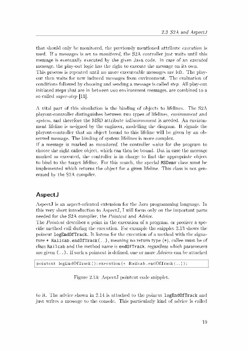
AspectJ is an aspect-oriented extension for the Java programming language. Inthis very short introduction to AspectJ, I will focus only on the important partsneeded for the S2A compiler, the Pointcut and Advice.The Pointcut describes a point in the execution of a program, or preciser a spe-ci�c method call during the execution. For example the snipplet 2.13 shows thepoincut logEndOfTrack. It listens for the execution of a method with the signa-ture * Railcab.endOfTrack(..), meaning no return type (*), callee must be ofclass Railcab and the method name is endOfTrack, regardless which parametersare given (..). If such a pointcut is de�ned, one or more Advices can be attached
po intcut logEndOfTrack ( ) : execut ion (∗ Rai lcab . endOfTrack ( . . ) ) ;
Figure 2.13: AspectJ pointcut code snipplet.
to it. The advice shown in 2.14 is attached to the poincut logEndOfTrack andjust writes a message to the console. This particularly kind of advice is called
19
2 Foundations
after()returning, which obviously starts directly after the method de�ned inthe pointcut is executed. Other possible kinds of Advices are before or around.It is to mention, that in the advice body any Java code can be executed. The
a f t e r ( ) r e tu rn ing : logEndOfTrack ( ){System . out . p r i n t l n (" logEndOfTrack has been executed " ) ;
}
Figure 2.14: AspectJ advice code snipplet
pointcuts and Advices are stored in the equivalent to .Java �les, the .aspectswhich must be compiled by an AspectJ compiler. The resulting bytecode can beexecuted by a standard Java interpreter.
2.4 Other tools and technologies
2.4.1 Activestructure-Editor
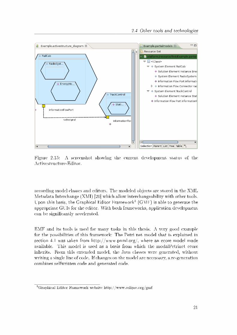
The Activestructure-Editor is currently being developed at the University ofPaderborn. With this editor the active structure can be modeled. The long-term goal is it to create multiple editors for the Mechatronic Modelling Languageas well. An advantage would be that each editor could use the same metamodeland thereby enable a cross-referencing between the editors. For example couldthe structure be modelled with the Activestructure-editor and later be used in thebehaviormodel-editor to specify the behavior with sequence diagrams. Screenshot2.15 shows the current development version of the Activestructure-Editor. Theeditor views left (freeform diagram) and right (tree-editor) show the same model.A Systemelement Railcab containing a RadioSystem and an EnergyModule con-nected with a TrackControl via an InformationFlow. This InformationFlow isrelayed by the InformationFlowPorts.The Activestructure-Editor is not a standalone application but consits of severalplugins for eclipse. Eclipse4 is an open source platform and has a plugin modelthat allows an easy extension to its basic features. Important plugins like EMF,GMF, and UML2 are described in more detail.
2.4.2 EMF & GMF
EMF is a set of eclipse plugins that allow the creation of metamodels and fromthis the generation of model, edit and editor code. EMF provides a user inter-face to �rst create a metamodel. and based on this the ability to generate the
4http://www.eclipse.org
20
2.4 Other tools and technologies
Figure 2.15: A screenshot showing the current development status of theActivestructure-Editor.
according model classes and editors. The modeled objects are stored in the XMLMetadata Interchange (XMI) [20] which allow interchangeability with other tools.Upon this basis, the Graphical Editor Framework5 (GMF) is able to generate theappropriate GUIs for the editor. With both frameworks, application developmentcan be signi�cantly accelerated.
EMF and its tools is used for many tasks in this thesis. A very good examplefor the possibilities of this framework: The Petri net model that is explained insection 4.1 was taken from http://www.pnml.org/, where an ecore model madeavailable. This model is used as a basis from which the modalPetrinet ecoreinherits. From this extended model, the Java classes were generated, withoutwriting a single line of code. If changes on the model are necessary, a re-generationcombines selfwritten code and generated code.
5Graphical Editor Framework website http://www.eclipse.org/gmf
21
2 Foundations
2.4.3 UML2 project
Them UML2 project6 aims are to provide a fully realization of the UML 2 stan-dard and the exemplary tools for developing models based on those metamodels.With the help of ecore models and EMF + GMF their editors for viewing andediting UML models already support class, component, state machine, and ac-tivity diagrams. Of course, the ecore metamodel can be extended and thereforereused in new plugin-projects or other editors. The models created by the UML2project editors are stored in XMI [20], which is already a common and well usedformat.
2.4.4 OCL
The Object Constraint Language is used to describe rules that apply to anymetamodels and models. The rules are formalized in a precise text language andcan be used to set constraints or create object query expressions. OCL can beused to specify invariants of objects and pre- and post conditions of operations,making UML (class) diagrams more precise (using vocabulary of UML class di-agrams). They add the ability to access attributes and navigate through UMLclass diagrams and, even more important for this thesis, through instantiatedEMF models. OCL supports collections, special operations, �lters, quanti�ers,iterations, and many more constructs. For this work, only simple conditions andthe navigation through the class model are used.
The code snipplet 2.16 checks two conditions: �rst if railcab1 and the passingRailcabhave the same trackcontrol object (isEqual). The second condition is a simplecheck if the attribute speed of the railcab1 is smaller than 100.
r a i l c a b 1 . currentTrackContro l=pass ingRa i l cab . currentTrackContro lAND ra i l c ab1 . speed <100
Figure 2.16: OCL code snipplet for simple condition checks.
6http://www.eclipse.org/uml2
22

3 Concepts
This chapter introduces concepts how the system behavior can be modeled ina scenario-based way. I also explain in which way this approach is connectedto the existing modelling techniques. Therefore a basic example which includesmultiple scenarios is given. These scenarios are then modeled using Modal se-quence diagrams. Based on this, a Tool-Vision explains the desired process andfunctionality of this modelling approach. It is also explained how a seamless in-tegration in the existing concepts can be achieved. One of the desired featuresis a simulation of the previously speci�ed behavior, which enables the analysis ofthe system during the conceptual design.
Section Modelling starts this chapter and shows the modelling of multiple scenar-ios for a mechatronic system with Modal Sequence Diagrams. Following this is theTool-Vision (3.2) explaining the desired modelling techniques and tool function-ality for this scenario-based development approach. Afterwards Scenario-Playout(3.3) details the prerequisites for a behavior simulation. Section 3.4 ObjectBind-ing investigates some problems that occurs when binding symbolic lifelines in adynamic object system. To conclude this chapter, I propose ideas and possiblesolutions how Object re�nement (3.5), the detailing of the objects innerworkings,can be achieved.
3.1 Modelling
It is desired to model (self-optimizing) mechatronic systems based on the designprocess currently development by the CRC 614.During the 'Conceptual design on system level ' phase, in each scenario new Func-tions, Structure and Behavior are created and existing ones reused. They areclosely related to each other, therefore a common metamodel and modelling lan-guage should allow to cross-reference between the di�erent partial models. Forexample would this allow the use of components de�ned in the active structureas lifelines in the behavior speci�cation.
In this section, I assume that the 'Task Analysis ' phase is completed and therelevant scenarios are identi�ed. The basis structure of the example is given andspeci�ed in an active structure diagram. It is modeled with the MechatronicModelling Language and is accompanied by the function hierarchy as described
23

3 Concepts
in section 2.1.2. Based on these scenarios, I will specify the behavior with theuse of Modal Sequence Diagrams. The MSDs use the components de�ned in theactive structure as lifelines. Hence, the communication between the componentscan be easily modeled by just drawing the messages.
The Railcab-system consists of many individual systems and subsystems, butin this example only a few will be used. These systems are primarily Railcabs,tracks, switches, and TrackControls. The Railcab is the core of this system. Theautonomous vehicles are able to solve problems on their own. This means thatthey are able to optimize themselves depending on the situation. These decisionscould for example be, how to optimize the driving mode for the next track sectionor should a convoy be created with the railcab in front.
Railcabs need TrackControls along the tracks. These TrackControls are impor-tant for the Railcabs linear drive to work, because it needs precise informationof its current position. Each TrackControl is responsible for one track and canperform additional tasks. Some of the tasks include managing the Railcabs thatare currently on their track, queueing cabs that want to enter, or just store infor-mation about the state of the track. With these information the railcabs are ableto autonomously decide which driving mode (fast,energy saving, comfort and soon) to use. To make this example simpler, I assume that each TrackControl canonly manage one track and knows only its previous and next TrackControl.SwitchControl is kind of a TrackControl. It is a system for managing switches,which has a slightly more complex Railcab management and more previous/nextassociations. The example in which all scenarios take part is relatively small.
Figure 3.1: Track plan for this example
Figure 3.1 shows a track plan in a more abstract form. There are two Railcabs
24

3.1 Modelling
on the route which consists of a ring of tracks and a shortcut that is branched bytwo SwitchTracks. The individual track sections are separated from each otherby the lines with blue dots.
For this thesis it was not possible to use the Mechatronic Modelling Language tomodel the structure, so an UML based model is used instead. Due to the fact thatthe current MML version is also based on UML, an UML representation of theactive structure elements is not a problem. The metamodel, that I use to createthe examples basis structure, is called Railcab. An overview of this metamodelis given in �gure 3.2 and shows the used classes, attributes and associations.The modeled basic structure consists of the 2x Railcabs, 2x Switches, 2x Switch-
Figure 3.2: Railcab metamodel created for this example
Track, 13x Track, 13x TrackControl and 2x SwitchControl. This corresponds tothe schematic trackplan given in �gure 3.1.
Scenario overview
For the Railcab project already numerous application-scenarios have been iden-ti�ed and de�ned on index cards. The basic content of these cards consists ofName, short description of the scenario, creation/modi�cation date, rough de-scription of the environment, objectives/goals and their priorisation, as well as asketch of the scenario. In this thesis, only a simple description of the scenarios isgiven. Additional information like objective priorities are not of concern for themodelling.For this example, four basic scenarios have been identi�ed:
25

3 Concepts
1. Railcab switches track: An important and regularly used scenario, spec-ifying a Railcab switching its current track. This scenario is also used for anobject re�nement, introducing the internal subcomponents of the Railcab.
2. Detect Railcab - create convoy: A Railcab that detects the proximityof another one - communication takes place to negotiate a possible convoymode.
3. Enter switch: This scenario is similar to 'Railcab switches track', butwith an improved Railcab management.
4. Disband convoy: The counterpart to the detect Railcab scenario. Aconvoy should be disbanded.
Despite that the scenarios are all independently modeled, they might overlap insome degree with each other. These intersections represent the cross-scenariospeci�cation, and possible inconsistencies can be revealed during the simulation.Figure 3.3 also shows the 'Detect track end' circle which is not a scenario, but�ts perfectly to show that it can be used by both scenarios. Each of them is now
Figure 3.3: Some of the identi�ed scenarios and how they might overlap.
described in detail and the according behavior modeled with Modal SequenceDiagrams.The following scenarios are modeled based on the MSD and LSC speci�cation.
3.1.1 Scenario: Railcab switches track
Since the �rst scenario shows many of the most important characteristics andsemantics, it is described in more detail than the other scenarios. The end of atrack has been reached and the Railcab must initiate steps to switch to the next
26
3.1 Modelling
track section. On a high abstraction level, the individual steps are shown thatmust be executed to achieve this track change. Later on, the internal componentsof the Railcab are speci�ed.
In order for a Railcab to leave its current track and switch to the next, it isnecessary to register at the TrackControl that is responsible for the upcomingtrack-section. Because the Railcab does not know the new TrackControl, it hasto query its current one for this additional information. Finally a registrationfollows, allowing the Railcab to request the entering of the next track. The sce-nario ends with the un-registration at the Railcabs current TrackControl.
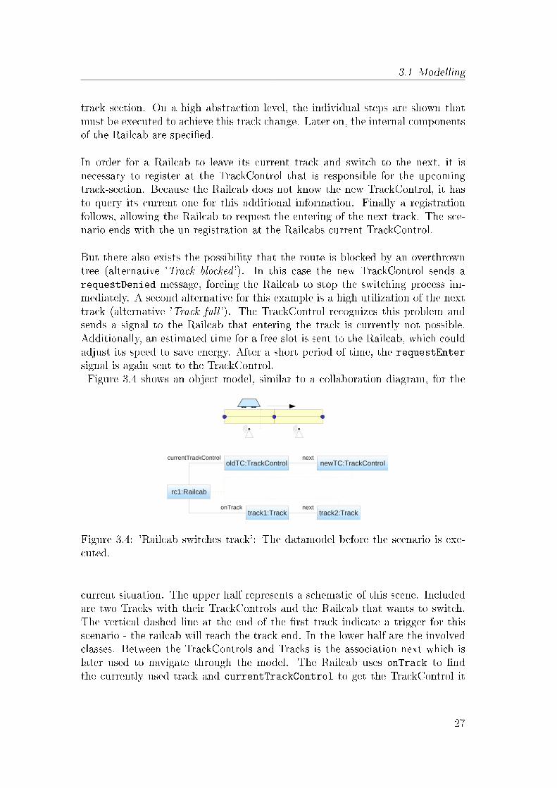
But there also exists the possibility that the route is blocked by an overthrowntree (alternative 'Track blocked '). In this case the new TrackControl sends arequestDenied message, forcing the Railcab to stop the switching process im-mediately. A second alternative for this example is a high utilization of the nexttrack (alternative 'Track full '). The TrackControl recognizes this problem andsends a signal to the Railcab that entering the track is currently not possible.Additionally, an estimated time for a free slot is sent to the Railcab, which couldadjust its speed to save energy. After a short period of time, the requestEntersignal is again sent to the TrackControl.Figure 3.4 shows an object model, similar to a collaboration diagram, for the
Figure 3.4: 'Railcab switches track': The datamodel before the scenario is exe-cuted.
current situation. The upper half represents a schematic of this scene. Includedare two Tracks with their TrackControls and the Railcab that wants to switch.The vertical dashed line at the end of the �rst track indicate a trigger for thisscenario - the railcab will reach the track end. In the lower half are the involvedclasses. Between the TrackControls and Tracks is the association next which islater used to navigate through the model. The Railcab uses onTrack to �ndthe currently used track and currentTrackControl to get the TrackControl it
27
3 Concepts
is registered at. The dashed lines represent the state after successfully switchingthe tracks.
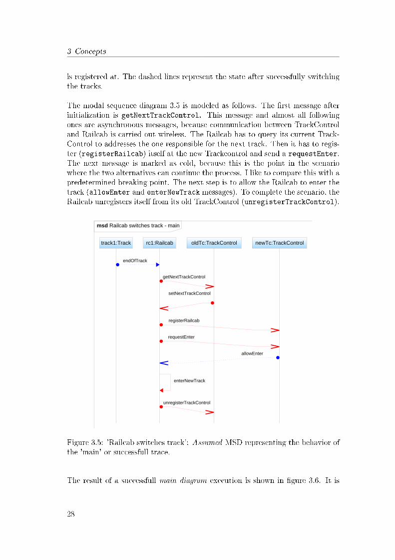
The modal sequence diagram 3.5 is modeled as follows. The �rst message afterinitialization is getNextTrackControl. This message and almost all followingones are asynchronous messages, because communication between TrackControland Railcab is carried out wireless. The Railcab has to query its current Track-Control to addresses the one responsible for the next track. Then it has to regis-ter (registerRailcab) itself at the new Trackcontrol and send a requestEnter.The next message is marked as cold, because this is the point in the scenariowhere the two alternatives can continue the process. I like to compare this with apredetermined breaking point. The next step is to allow the Railcab to enter thetrack (allowEnter and enterNewTrack messages). To complete the scenario, theRailcab unregisters itself from its old TrackControl (unregisterTrackControl).
Figure 3.5: 'Railcab switches track': Assumed MSD representing the behavior ofthe 'main' or successfull trace.
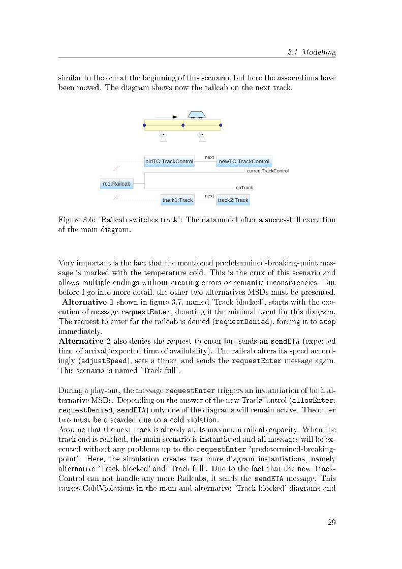
The result of a successfull main diagram execution is shown in �gure 3.6. It is
28
3.1 Modelling
similar to the one at the beginning of this scenario, but here the associations havebeen moved. The diagram shows now the railcab on the next track.
Figure 3.6: 'Railcab switches track': The datamodel after a successfull executionof the main diagram.
Very important is the fact that the mentioned predetermined-breaking-point mes-sage is marked with the temperature cold. This is the crux of this scenario andallows multiple endings without creating errors or semantic inconsistencies. Butbefore I go into more detail, the other two alternatives MSDs must be presented.Alternative 1 shown in �gure 3.7, named 'Track blocked', starts with the exe-cution of message requestEnter, denoting it the minimal event for this diagram.The request to enter for the railcab is denied (requestDenied), forcing it to stopimmediately.Alternative 2 also denies the request to enter but sends an sendETA (expectedtime of arrival/expected time of availability). The railcab alters its speed accord-ingly (adjustSpeed), sets a timer, and sends the requestEnter message again.This scenario is named 'Track full'.
During a play-out, the message requestEnter triggers an instantiation of both al-ternative MSDs. Depending on the answer of the new TrackControl (allowEnter,requestDenied, sendETA) only one of the diagrams will remain active. The othertwo must be discarded due to a cold violation.Assume that the next track is already at its maximum railcab capacity. When thetrack end is reached, the main scenario is instantiated and all messages will be ex-ecuted without any problems up to the requestEnter 'predetermined-breaking-point'. Here, the simulation creates two more diagram instantiations, namelyalternative 'Track blocked' and 'Track full'. Due to the fact that the new Track-Control can not handle any more Railcabs, it sends the sendETA message. Thiscauses ColdViolations in the main and alternative 'Track blocked' diagrams and
29

3 Concepts
Figure 3.7: 'Railcab switches track': The two, small alternative endings to themain diagram.
leads to their termination. Only 'Track full' remains and the simulation proceedsnormally. Figure 3.8 is a visualization of this process. By using this modelling
Figure 3.8: 'Railcab switches track': Visualization of the di�erent endings for thecase of an 'track full' end. Cold violations discard the remaining two diagrams.
technique, an engineer who creates such a behavior diagram is now able to spec-ify alternative endings. Of course it would also be possible to use an alternative,but this approach allows a separate modelling of these diagrams. Beside this,other scenarios may use the alternative endings as well. The set of endings canbe extended or reduced by simply adding or removing diagrams - and all withoutthe need of modifying existing ones.
30

3.1 Modelling
Re�nement: Detect track end
An engineer who has already modeled the �rst scenario at a high abstractionlevel might want to bring more detail into the behavior. It is desired to modelan object re�nement independently from the scenario, which allows the re-use ofthe re�ned behavior in other scenarios. This re�nement is done by de�ning theinnerworkings of the Railcab and their behavior.
This re�nement can be interpreted like a zoom into the diagram and the creationof a new MSD for the included subcomponents. Messages send and received bythe Railcab are indicated by incoming and outgoing gates. Gates allow messagesto that start or end at the border of the diagram, and can be an easy way tomodel the passing of information between a sequence diagram and its context.In section 3.5 'Hierarchical re�nement', two ways to model such a re�nement areexplained.
For this scenario the Railcabs internal subcomponents 'Distance MeasurementUnit ' (short DMU) in combination with a 'Track-End-Coordinator ' (TEC) anda RadioSystem are used. The DMU is a sensor that scans the rail bumpers for amarking that indicates the end of the track. If such a bumper is discovered, theTrack-End-Coordinator is informed. This component is responsible for gettinginformation about the next track, requesting the next TrackControl and manymore. The third new subcomponent is a RadioSystem to communicate with otherTrackControls or Railcabs. The according Active Structure is modeled in �gure3.9 and includes also a modi�ed TrackControl.The following two MSDs show only the needed lifelines & messages to save some
Figure 3.9: 'Detect track end': New, re�ned Active Structure of the Railcabshowing two subcomponents and the connected TrackControl.
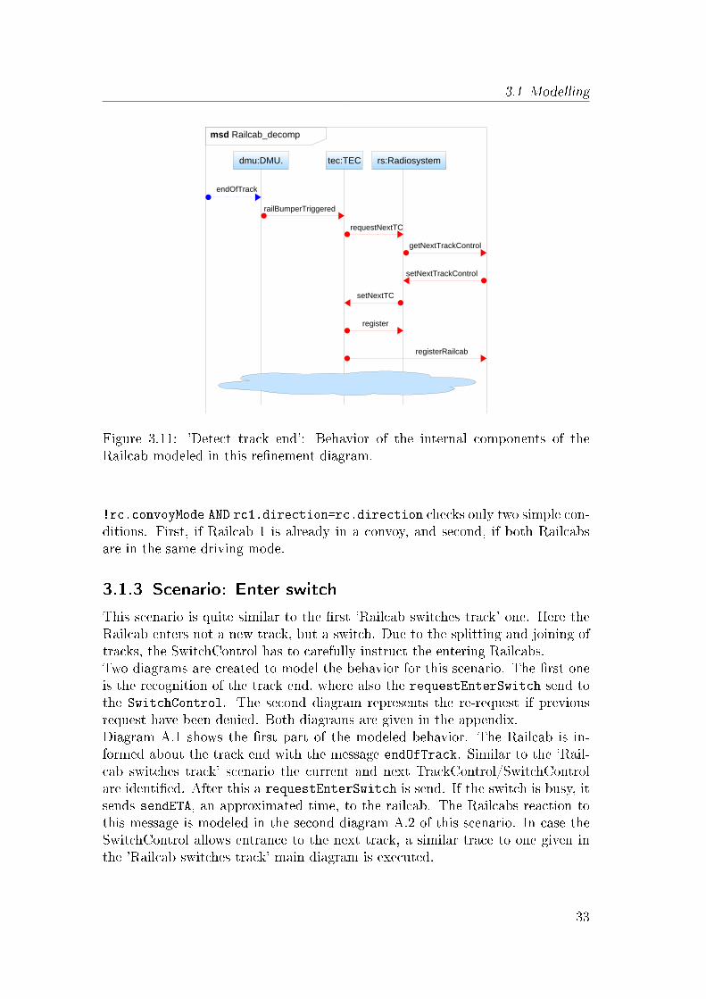
space and to focus on the important parts. The complete diagrams are given inthe appendix. The �rst diagram 3.10 is a modi�ed version of the 'Railcab switchestrack' scenario. I added a dashed, gray rectangle to indicate the lifeline/object Iwant to re�ne. The second diagram 3.11 represents the re�nement of the Railcab.
31

3 Concepts
Figure 3.10: 'Detect track end': MSD from scenario 'Railcab switches track' thatis used to re�ne the Railcab, indicated by the scenario name above it.
The original incoming and outgoing messages are relayed by the gates at thediagram borders.
3.1.2 Scenario: Detect Railcab - create convoy
This scenario is about the recognition of other nearby Railcabs and the questionwhether to form a convoy or not.The Railcabs can detect each other via a short-range radio. This radio system isalso used to exchange information between them.The behavior modeled in �gure 3.12 shows such an information exchange. The�rst Railcab approaches and recognizes the radio signals of a second Railcab inits proximity. It sends a signal to this Railcab and introduces itself. Triggeredby this, the detected Railcab sends its current information on speed, target des-tination, modes of operation, etc. to its �nder. In addition, the callee Railcabasks for the same information in return. Based on these information, the callerRailcab decides whether it should form a convoy or not.
The according Modal Sequence Diagram re�ects this communication in detail.The diagram is initialized with the message detectRailcabProximity. Whenthe message is received, the Railcabs exchange their information by sendingthe sendCruiseInformation message. In this example the assert condition
32
3.1 Modelling
Figure 3.11: 'Detect track end': Behavior of the internal components of theRailcab modeled in this re�nement diagram.
!rc.convoyMode AND rc1.direction=rc.direction checks only two simple con-ditions. First, if Railcab 1 is already in a convoy, and second, if both Railcabsare in the same driving mode.
3.1.3 Scenario: Enter switch
This scenario is quite similar to the �rst 'Railcab switches track' one. Here theRailcab enters not a new track, but a switch. Due to the splitting and joining oftracks, the SwitchControl has to carefully instruct the entering Railcabs.Two diagrams are created to model the behavior for this scenario. The �rst oneis the recognition of the track end, where also the requestEnterSwitch send tothe SwitchControl. The second diagram represents the re-request if previousrequest have been denied. Both diagrams are given in the appendix.Diagram A.1 shows the �rst part of the modeled behavior. The Railcab is in-formed about the track end with the message endOfTrack. Similar to the 'Rail-cab switches track' scenario the current and next TrackControl/SwitchControlare identi�ed. After this a requestEnterSwitch is send. If the switch is busy, itsends sendETA, an approximated time, to the railcab. The Railcabs reaction tothis message is modeled in the second diagram A.2 of this scenario. In case theSwitchControl allows entrance to the next track, a similar trace to one given inthe 'Railcab switches track' main diagram is executed.
33

3 Concepts
Figure 3.12: 'Detect Railcab - create convoy': Simple message trace completedthrough an alternative fragment.
To keep the scenarios and diagrams simple, the MSD specifying the Railcabswaiting to enter the switch, consist only of three elements. The �rst element isthe sendETA message send by the SwitchControl. Then a timer is started. Afterthe time has passed, a new requestEnter message is send. The timer can ofcourse be replaced by more complicated actions, as for example slowing down theRailcab to save energy.
3.1.4 Scenario: Disband convoy
The initial situation for this scenario is an already formed convoy with two ormore Railcabs. One of the Railcabs has to leave the convoy. A switch is theonly possibility for a Railcab to leave the current track. A station is not directlyattached to the main track, but separated from it by a switch.
If a Railcab wants to leave the convoy, an adequate distance to the predecessorand successor Railcab must be established. In case the Railcab is the leader ofthe convoy, only the predecessor has to be informed. If the Railcab is the last
34

3.2 Tool vision
shuttle in the convoy, its successor has to be informend. In the last case bothRailcabs. The resulting MSD for this scenario is modeled in diagram A.3.The diagram is triggered by listening to the allowEnter message, which is sentfrom a SwitchControl to the Railcab. If the Railcab wants the leave the track,the condition in the next assert must be evaluated true. Next, one of the fol-lowing alternative-parts is entered. It is checked whether the Railcab is leaderof the convoy, at the end or somewhere in between. Each alternative-part in-forms, depending on this, its predecessor and successor Railcabs. After thedisbandNotifications has been send, the Railcab prepares to leave the track.It reduces its speed to create the necessary distance.
3.2 Tool vision
The goal is to analyze the created models as early as possible. One way to analyzea design is to simulate it, which can be realized as follows. First the Functions, theActive Structure, and the Behavior are modeled for each scenario independently.The MML metamodel (2.1.2) allows us to capture the relationship between thestructure and behavior. This provides the ability to cross-reference elements. Insection Modelling I presented this behavior modelling process for some scenarios.
A scenario-playout (see section 2.2.2) is used simulate the behavior that is mod-eled independently for each scenario with these diagrams. The play-out shouldallow an engineer to simulate a modeled system by
• using previously de�ned structure elements to create an example environ-ment for simulating the static and dynamic parts.
• start, observe, and in�uence the behavior simulation by inducing environ-ment events
A possible use case can look like the following. An engineer working on one ormore scenarios uses the de�ned structures to generate the needed classes to modelan example system. After creating the test system the developer can execute asimulation by inducing external events into the system. This permits him to takethe role of the environment. Inducing external events can of course be automatedby de�ning test cases in form of event sequences. Based on the previously de�nedModal Sequence Diagrams, the play-out engine starts the simulation. The com-ponents are dynamicly bound to the lifelines, allowing a �exible change of theinstance structure. During this simulation the engineer can observe the commu-nication between the components. A message trace and changes directly at theinstantiated example objects can be used to analyze the behavior. Discoverederrors and violations can indicate contradictions in the design. It is also possibleto interact with the play-out, by forcing the play-outs strategy to prefer somemessage.
35
3 Concepts
The task of this thesis was to investigate how to model and simulate the ModalSequence Diagrams in the context of the tool vision sketched above. I �rst in-vestigated two other existing play-out approaches. The S2A compiler, which Iintroduced in section 2.3, was not suited for our purposes, because it needs fullyfunctioning (implemented) code to execute. In addition to this a second compileris necessary to compile the AspectJ code into bytecode. To support a dynamicobject system, a special controller has to be manually created to bound objects tolifelines according to the current context. This controller has to be modi�ed foreach change in the object model. S2A is speci�cally designed for Modal SequenceDiagrams. If a change is necessary, like adding additional elements or constructs,the play-out engine can not be modi�ed easily.The second available simulation tool is the Play-Engine from Harel and Marelly[14].An integration of this standalone tool into the existing eclipse plugins is very dif-�cult. The objects system of this approach would complicate the realization ofdynamic structures and component systems.Because of this I decided to develop a new eclipse based simulation plugin.
The concepts and tool features which I introduce in the following are the basisfor the vision given above. I developed concepts to play-out the created diagramsand thereby being able to simulate the systems behavior. For this, the alreadypresented Modal Sequence Diagrams need to be modi�ed.I also provide an elegant way to cope the dynamic object system and the re-sulting binding problems. To be able to integrate my simulation approach intothe existing tool suite, all simulation related concepts are based on the eclipseplatform. This enables the use of plugins like EMF to generate model and editorcode easily. My idea is to be able to simulate the modeled behavior right afterspeci�cation, by using a system/environment to test with.The toolsuite will allow an engineer to model the di�erent aspects of each sce-nario and afterwards analyze the system by simulating it.
3.3 Scenario-Playout
In the following I explain the concepts of the play-out I developed. It introducesthe interpretation of MSDs as modi�ed Petri nets and their new elements. Afterthis, each section covers a di�erent part of the simulation, which concepts aredescribed independently. This way important topics, like initialization and vio-lations, are introduced step by step. To complete the play-out, the previouslypresented concepts are combined in the the basic play-out simulation routine.
36
3.3 Scenario-Playout
3.3.1 Trace semantics of MSDs as a Petri net
The �rst and most noticeable di�erence to S2A is that I don't use automatonsto represent the Modal Sequence Diagrams. The conversion process maps a pos-sible trace described by an MSD to an extended Petri net. This transformedPetri net has some advantage over its LSC source, because model checking canbe performed more easily [3, 1]. Additional, but minor advantages are that par-allel events lead to complicated states in an automaton, but remain small andrecognizable in a Petri net. Events that have more than one dependency to beenabled, can be expressed better. For example is it possible that a receive eventhas a predecessor on its lifeline and a sending event on a di�erent one. Bothpreceding events must be enabled, before the receive event can be �red. Thiskind of behavior can be modeled very well with Petri nets.
Here I use Petri nets and extend them by additional attributes like temperaturewhich is also known from LSCs. I denote this kind of Petri net as modalPetrinet.It is based on existing approaches converting sequence diagrams to Petri nets like[17, 16, 1]. The basic idea is to translate each event in a MSD to a transition ina Petri net. All the MSD elements that are currently needed for the simulationcan be converted in this way.
Each lifeline of a sequence diagram is covered by MessageOccurenceSpeci�cations.These MessageOccurenceSpeci�cations represent events which can be SendEvent,ReceiveEvent or CombinedFragmentEvent that I explain in the following.SendEvent and ReceiveEvent are the ends of a message. CombinedFragmentEventsare di�erent, because they can actually cover multiple lifelines. The two types ofCombinedFragments used in this thesis are AlternativeCombinedFragments andAssertCombinedFragments, which are both described in the foundations chapter.More information about these elements can be found in OMGs UML speci�ca-tion [19]. An important fact of sequence diagrams is, that all the elements on alifeline are ordered. With this information it is possible to insert arcs and placesto recreate the lifeline ordering using the according transitions. The relationshipof send and receive events can also be modeled this way, regardless of the lifelinethey are covering.
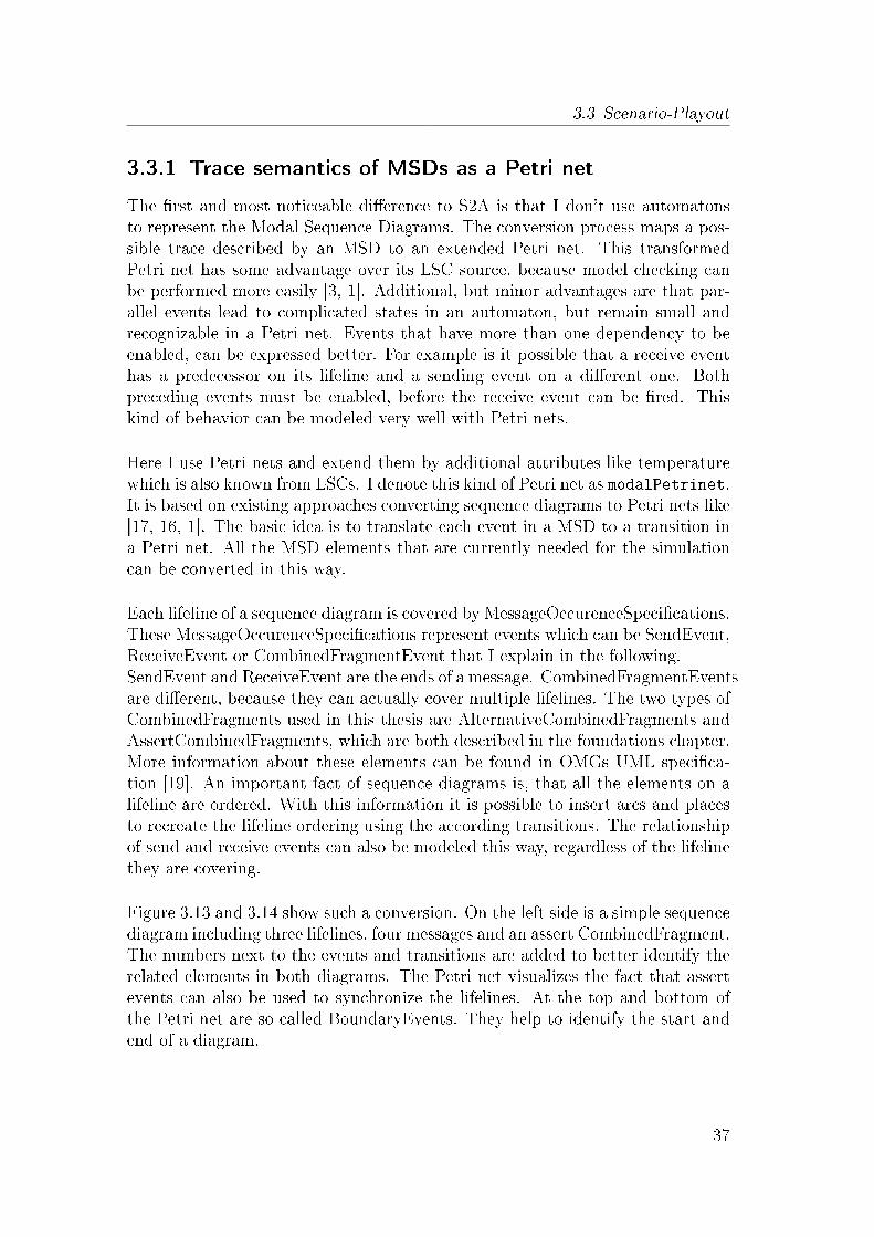
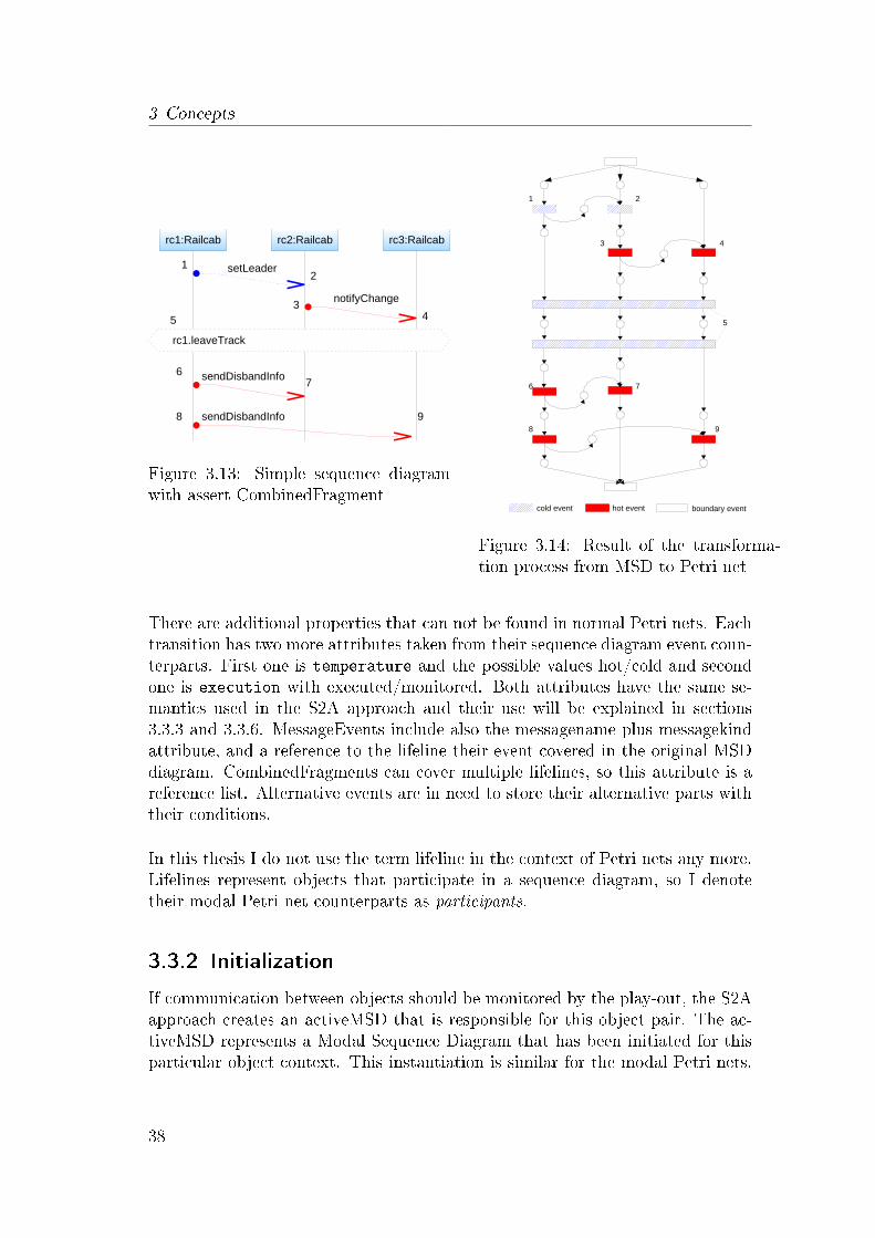
Figure 3.13 and 3.14 show such a conversion. On the left side is a simple sequencediagram including three lifelines, four messages and an assert CombinedFragment.The numbers next to the events and transitions are added to better identify therelated elements in both diagrams. The Petri net visualizes the fact that assertevents can also be used to synchronize the lifelines. At the top and bottom ofthe Petri net are so called BoundaryEvents. They help to identify the start andend of a diagram.
37
3 Concepts
Figure 3.13: Simple sequence diagramwith assert CombinedFragment
Figure 3.14: Result of the transforma-tion process from MSD to Petri net
There are additional properties that can not be found in normal Petri nets. Eachtransition has two more attributes taken from their sequence diagram event coun-terparts. First one is temperature and the possible values hot/cold and secondone is execution with executed/monitored. Both attributes have the same se-mantics used in the S2A approach and their use will be explained in sections3.3.3 and 3.3.6. MessageEvents include also the messagename plus messagekindattribute, and a reference to the lifeline their event covered in the original MSDdiagram. CombinedFragments can cover multiple lifelines, so this attribute is areference list. Alternative events are in need to store their alternative parts withtheir conditions.
In this thesis I do not use the term lifeline in the context of Petri nets any more.Lifelines represent objects that participate in a sequence diagram, so I denotetheir modal Petri net counterparts as participants.
3.3.2 Initialization
If communication between objects should be monitored by the play-out, the S2Aapproach creates an activeMSD that is responsible for this object pair. The ac-tiveMSD represents a Modal Sequence Diagram that has been initiated for thisparticular object context. This instantiation is similar for the modal Petri nets.
38

3.3 Scenario-Playout
Each Petri net has also a triggering minimal event. If the play-out recognizesthis event, the according modal Petri net is determined. Instead of creating anew instance of the diagram, a new con�guration is initialized. A con�gurationis used to store the current cut and to keep keep track of the binding. The cutis represented by set of places that currently hold at least one token. In a MSD,objects are bound to a lifelines. The modal Petri nets on the other hand, managesa list of participants and their bound objects. To check which object is bound toan event or vice versa, the play-out just needs to get the participant and lookupthe object.The con�gurations are called ActivePNCon�guration and represent the counter-parts to the S2A's activeMSD.
3.3.3 Hot/Cold Violations
Checking for violations in modal Petri nets is di�erent to the check S2A uses. Inthe S2A approach the controller uses a state automaton to represent the MSDas described in section 2.2.3 'Modal Sequence Diagrams'. In addition to the nor-mal end state are the Hot-Violation and Cold-Violation states. If the automatonstops in these special states a violation has occurred.
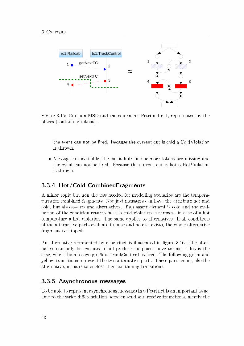
For Petri nets exists an adequate way to �nd violations with the use of cuts. Torecall, the de�nition of a hot/cold cut is: �A cut is hot if one of its locationsis hot and is cold otherwise [18]. The cut is advanced by �rering a transitionand thereby enabling the following, depending transitions. A cut in a MSD isrepresented by a set of places containing tokens in a modal Petri net. Figure3.15 illustrates this representation. The MSD has a cut through the messagesetNextTC, after event three but before event four.
With the additional transition attribute temperature, I can now check for a cold orhot violation by inspecting the places of a cut, respectively their next transitions.The following steps take only e�ect if the diagram is already instantiated and theparticipants are bound. Similar to the S2A approach, a message sent betweentwo objects is checked if it is used anywhere else in the diagram. This is theequivalent to the set M, containing all messages of the whole diagram. If themessage is not found in the set M, the check ends without a violation. Otherwiseone of the following cases is executed:
• Message available: all tokens to �re the transitions for the message areavailable. The message is executed regardless of the cuts temperature. Thisadvances the cut, consuming tokens and moving them to the transitionsoutgoing places. No violation is thrown.
• Message not available, the cut is cold: one or more tokens are missing and
39
3 Concepts
Figure 3.15: Cut in a MSD and the equivalent Petri net cut, represented by theplaces (containing tokens).
the event can not be �red. Because the current cut is cold a ColdViolationis thrown.
• Message not available, the cut is hot: one or more tokens are missing andthe event can not be �red. Because the current cut is hot a HotViolationis thrown.
3.3.4 Hot/Cold CombinedFragments
A minor topic but non the less needed for modelling scenarios are the tempera-tures for combined fragments. Not just messages can have the attribute hot andcold, but also asserts and alternatives. If an assert element is cold and the eval-uation of the condition returns false, a cold violation is thrown - in case of a hottemperature a hot violation. The same applies to alternatives. If all conditionsof the alternative parts evaluate to false and no else exists, the whole alternativefragment is skipped.
An alternative represented by a petrinet is illustrated in �gure 3.16. The alter-native can only be executed if all predecessor places have tokens. This is thecase, when the message getNextTrackControl is �red. The following green andyellow transitions represent the two alternative parts. These parts come, like thealternative, in pairs to enclose their containing transitions.
3.3.5 Asynchronous messages
To be able to represent asynchronous messages in a Petri net is an important issue.Due to the strict di�erentiation between send and receive transitions, merely the
40

3.3 Scenario-Playout
Figure 3.16: On the left side a MSD with an alternative, on the right side theequivalent representation as a modal Petri net.
execution of a message is slightly di�erent. The rules for executing both kinds ofmessages are:
• Synchronous messages can only be send if both (send and receive) tran-sitions can be �red.
• Asynchronous messages only need tokens in every place that will beconsumed by the sender, respectively receive transition.
It is also valid to model the send and receive event of an asynchronous messagewith di�erent temperatures. A good example for this is a wireless communication.A message must be sent (hot) but is not necessarily received at the other end(cold). This opens new ways to model behavior and can be used to create adiagram dedicated for wireless communication. Everytime such a communicationis initiated, this diagram is triggered and a it must be decided, if the messageshould be altered, dropped, or (perfectly) transmitted.
3.3.6 Message selection and Playout-Strategies
In the introduction to the modal Petri nets, the additional attribute executionhas been mentioned. A message with the attribute set to monitored will not bechosen by the simulation engine for execution. Therefore is a executed messageadded to a pool of possible next messages. The S2A controller sorts messages in
41
3 Concepts
the same way.
This leads to the PlayoutStrategies and the PlayoutStrategyManager. A Playout-Strategy is the component of the simulation that chooses the next message thatshould be executed. This selection can be based on rules, a prede�ned order orjust a random pick.The task of the PlayoutStrategyManager is to choose the strategy that �ts bestfor the current situation.
3.3.7 Playout
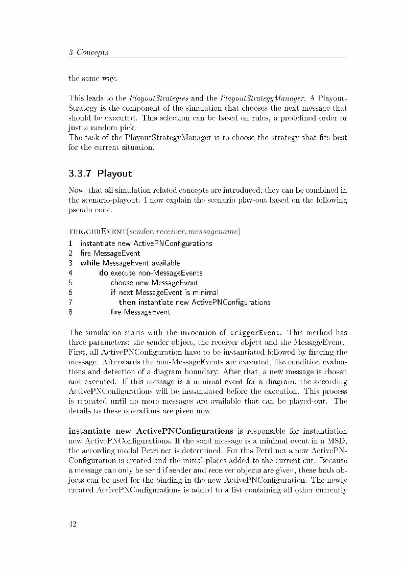
Now, that all simulation related concepts are introduced, they can be combined inthe scenario-playout. I now explain the scenario play-out based on the followingpseudo code.
triggerEvent(sender, receiver, messagename)
1 instantiate new ActivePNCon�gurations
2 �re MessageEvent
3 while MessageEvent available
4 do execute non-MessageEvents
5 choose new MessageEvent
6 if next MessageEvent is minimal
7 then instantiate new ActivePNCon�gurations
8 �re MessageEvent
The simulation starts with the invocation of triggerEvent. This method hasthree parameters: the sender object, the receiver object and the MessageEvent.First, all ActivePNCon�guration have to be instantiated followed by �rering themessage. Afterwards the non-MessageEvents are executed, like condition evalua-tions and detection of a diagram boundary. After that, a new message is chosenand executed. If this message is a minimal event for a diagram, the accordingActivePNCon�gurations will be instantiated before the execution. This processis repeated until no more messages are available that can be played-out. Thedetails to these operations are given now.
instantiate new ActivePNCon�gurations is responsible for instantiationnew ActivePNCon�gurations. If the send message is a minimal event in a MSD,the according modal Petri net is determined. For this Petri net a new ActivePN-Con�guration is created and the initial places added to the current cut. Becausea message can only be send if sender and receiver objects are given, these both ob-jects can be used for the binding in the new ActivePNCon�guration. The newlycreated ActivePNCon�gurations is added to a list containing all other currently
42

3.4 Object Binding
instantiated diagrams.
�re messageevent is used to �re the message and advance the cut of all a�ectedActivePNCon�gurations. An important function of this operation is to check forHot/Cold Violations. If a MessageEvent is �red, the sender and receiver objectsare determined. Then all ActivePNCon�gurations containing these both objectsare then checked for a violation. If no violation is thrown, the cut will be ad-vanced. In case a hot violation occurs, the simulation terminates.
execute non-MessageEvents processes alternative, assert, and assignmentevents. The conditions of assert and alternative are checked and assignmentsare executed if possible. Special events like the boundary are handled in this op-eration as well. It is important that all available non-messageevents are executed,and not just one.
choose new messageevent represents the selection of a new MessageEvent forthe next execution. The PlayoutStrategyManager picks a �tting Strategy, andthe Strategy chooses the next messageevent that will be executed.
3.4 Object Binding
This section is about how the objects are bound to the lifeline in a dynamicobject model. Binding is used to map a lifeline to a speci�c object, respectivelya participant to an Active Structure solution or system element. In a dynamicobject system, binding is more complicated, because it is not possible to refer to aspeci�c (static) object. The �xed sub-components of a Railcab represent a staticobject system. A simulation on a higher abstraction level with a several, movingRailcabs and TrackControls is an example for a dynamic object model. In andynamic environment, each lifeline is must be bound to an object depending onits current context. If a lifeline can not be bound it is not possible to use it tosend or receive messages.Next, I introduce two types of binding that I named 'Conventional Binding ' and'Extended Binding '.
3.4.1 Symbolic lifelines
An important characteristic of this approach is the use of only symbolic lifelines.Despite the fact that all lifelines are named, these names only represent identi�erslike variable names.As previously mentioned are both, static and dynamic objects systems used. Tobe able to cope with both types, all lifelines are set to symbolic. This allows the
43

3 Concepts
developer to design the diagram like a pattern, matching the current situation.Now lifelines can, even if di�erently named, reference the same object. It wouldnot be possible to use the extended binding or the other OCL condition checkswithout this representation.In case a non-symbolic lifeline is needed, this can be easily achieved by usingan appropriate OCL query to bind the desired lifeline always to the same targetobject.
3.4.2 Conventional Binding
Conventional Binding is used at the creation of an ActivePNCon�guration. Theminimal message that triggered the instantiation is send between already boundlifelines. This information can be used to bind the �rst lifelines in the newActivePNCon�guration. Conventional Binding occurs only if minimal messagesare send, all other lifelines are bound to objects with the Extended Binding.Messages that are induced by the environment always contain sender and receiverobjects.
3.4.3 Extended Binding
At least one lifeline is bound during the creation of an ActivePNCon�guration.The problem is how to map the remaining lifelines to their expected compo-nents/elements if there exist no additional information how the lifelines are re-lated to each other. An example for this is a diagram with three lifelines. Atinitialization, the �rst two lifelines are bound, because sender and receiver objectswere given by the minimal message. The third lifeline, which is somehow relatedto the other two lifelines, must also be bound.To �nd the appropriate object for a lifeline I developed a new concept namedextended binding. It is a combination of modi�ed assert events and the ObjectConstraint Language (OCL).
Each ActivePNCon�guration manages its binding in the form of Lifeline-Objectpairs. A lifeline has the attributes representsClass to reference the required type,and name which is the lifelines identi�er. With these information it is possibleto create the OCL Environment, representing a set of name-to-object mappings.For each already bound Lifeline-Object pair, a variable in the OCL environmentis created using the lifelines name and the bound object. Now OCL expressionscan be used to navigate through the instances and query attributes and refer-ences.These queries are used to return an object and to bound it to its according lifeline.To use this kind of binding in MSDs easily during modelling, an assert event witha modi�ed condition is used. The query expression to �nd the value or reference
44
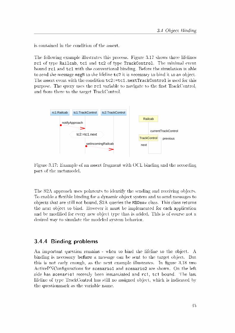
3.4 Object Binding
is contained in the condition of the assert.
The following example illustrates this process. Figure 3.17 shows three lifelinesrc1 of type Railcab, tc1 and tc2 of type TrackControl. The minimal eventbound rc1 and tc1 with the conventional binding. Before the simulation is ableto send the message msgB to the lifeline tc2 it is necessary to bind it to an object.The assert event with the condition tc2:=tc1.nextTrackControl is used for thispurpose. The query uses the rc1 variable to navigate to the �rst TrackControl,and from there to the target TrackControl.
Figure 3.17: Example of an assert fragment with OCL binding and the accordingpart of the metamodel.
The S2A approach uses pointcuts to identify the sending and receiving objects.To enable a �exible binding for a dynamic object system and to send messages toobjects that are still not bound, S2A queries the MSDenv class. This class returnsthe next object to bind. However it must be implemented for each applicationand be modi�ed for every new object type that is added. This is of course not adesired way to simulate the modeled system behavior.
3.4.4 Binding problems
An important question remains - when to bind the lifeline to the object. Abinding is necessary before a message can be sent to the target object. Butthis is not early enough, as the next example illustrates. In �gure 3.18 twoActivePNCon�gurations for scenario1 and scenario2 are shown. On the leftside has scenario1 recently been instantiated and rc1, tc1 bound. The lastlifeline of type TrackControl has still no assigned object, which is indicated bythe questionmark as the variable name.
45

3 Concepts
If the binding of ?:TrackControl follows after messages msgA and msgB, a poten-tial hot violation is missed. This can happen if in scenario2 the TrackControltc2 sends a message to rc1, and the objects are the same in both diagrams. Ifthe last remaining variable ? is then bound to tc2, a hot violation should haveoccurred at msgB, but has not. To avoid these late binding problems, all lifelines
Figure 3.18: A potential hot violation is missed due to the late binding of tc2.
must be bound during creation of the diagram instantiation. A binding as lateas possible is not allowed any more. With these restrictions it is now regardlesswhere in the diagram the bindings are de�ned as long as they are all processedduring initialization. Whether to use the binding assert fragments before the �rstuse, or right at the top of the diagram remains a question of visual appealing -as long as all lifelines get bound.
Another idea how this binding can be achieved is to use an external list, at-tached to the diagram called 'Object Navigation Constraints ' (see illustration3.19). This way no additional elements in the diagram are needed. The ONC-list is represented by a directed acyclic graph with the top elements bound bythe conventional binding. The order of this binding is indicated by the directedgraph. In the �gure, track1:Track and rc1:Railcab represent these elements.They are also connected with an arc with rectangles at both ends to indicate thisconventional binding. The other lifelines are bound by using existing associationsor OCL queries like the assert bindings. It is not necessary to add variable nameshere any more. This could improve the readability in more complex scenarios.For this thesis, I continue to use the modi�ed asserts in order to show the bindingin the diagrams.
One last issue that needs to be mentioned is the NULL-binding. Scenario 'Disbandconvoy' (3.1.4) indicates, or reveals such a problem. If the Railcab that wants to
46
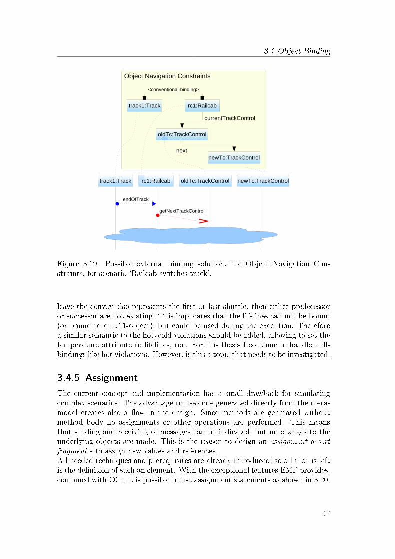
3.4 Object Binding
Figure 3.19: Possible external binding solution, the Object Navigation Con-straints, for scenario 'Railcab switches track'.
leave the convoy also represents the �rst or last shuttle, then either predecessoror successor are not existing. This implicates that the lifelines can not be bound(or bound to a null-object), but could be used during the execution. Thereforea similar semantic to the hot/cold violations should be added, allowing to set thetemperature attribute to lifelines, too. For this thesis I continue to handle null-bindings like hot violations. However, is this a topic that needs to be investigated.
3.4.5 Assignment
The current concept and implementation has a small drawback for simulatingcomplex scenarios. The advantage to use code generated directly from the meta-model creates also a �aw in the design. Since methods are generated withoutmethod body no assignments or other operations are performed. This meansthat sending and receiving of messages can be indicated, but no changes to theunderlying objects are made. This is the reason to design an assignment assertfragment - to assign new values and references.All needed techniques and prerequisites are already introduced, so all that is leftis the de�nition of such an element. With the exceptional features EMF provides,combined with OCL it is possible to use assignment statements as shown in 3.20.
47

3 Concepts
To prevent a misunderstanding - it is of course not allowed to change lifeline
r a i l c a b 1 . currentSpeed :=400
Figure 3.20: Assigning a new speed value of 400 to the railcab1.
variables, only object values and references.
3.5 Hierarchical re�nement
Object re�nement is used to specify the details of components and system ele-ments. During simulation it allows the engineer to get a more detailed view of aspeci�c objects behavior. To re�ect the design process in the 'Conceptual designon module level' phase, an incremental re�nement of components and diagramsshould be possible. For a Railcab, this design process starts on the level of thedistributed mechatronic system (DMS II). At this level it is for example speci�ed,how transport requests are generated or how the shuttle transports people andgoods from one location to the other. At the next level (DMS I), it is modeledhow the Railcab has to operate in certain situations, e.g. when forming a con-voy, switching a track, detecting an obstacle, and so on. Based on this level,sub-components like Sensors, Communication modules, Energy-supply and theirinteractions are derived. Scenario 'Railcab switches track' (3.1.1) gives an ideahow such a re�nement could look like. In the following I denote a diagram thatis used to re�ne an object or lifeline as re�nement diagram. The diagram thatcontains the object or lifeline that is re�ned is denoted in this thesis parent dia-gram.
There is a di�erentiation between two types of re�nement.The �rst way is to create a new diagram that represents a whole lifeline of theparent diagram. This is illustrated in �gure 3.21 which shows a simpli�ed ver-sion of the 'Railcab switches track' scenario. The Railcab lifeline in the upperDMS I level is re�ned by a scenario modeled in the lower, module/componentslevel. Gates at the diagram border are used to model the passing of informationbetween the sub-components and its context. This way, the original messageendOfTrack send from the Track to the Railcab is carried over to the internalcomponents.The re�nement diagram is connected to its parent diagram lifeline in a 1:1 re-lation, so there exists no other re�nement for it. This modelling technique tospecify behavior of sub-components is introduced by Atir, Harel,Kleinbort, andMaoz in [2]. The S2A compiler makes use of the 1:1 relationship to combine allre�nement diagrams into their parent diagrams and then to compile it to Sce-
48

3.5 Hierarchical re�nement
Figure 3.21: The MSD Railcab_decomp_1 is the re�nement diagram for theupper rc1:Railcab lifeline.
narioAspects. This kind of re�nement I call lifeline refinement, due to itsrelation to a speci�c lifeline.
The second way to model the behavior of subcomponents is not to re�ne a lifeline.Instead, multiple re�nement diagrams can be created for one object, resulting ina 1:n relationship between object and diagrams. This allows the developer tomodel di�erent parts of the behavior like he would usually do. Alternative end-ings and cross-diagram synchronization with messages can be achieved with thiskind of re�nement. Most important is the fact that the re�nement diagrams canbe used in other parent diagrams as well. This technique I call object re�nement.Figure 3.22 shows a high level diagram with Track, TrackControl, and Railcablifelines. For the TrackControl and Railcab also multiple re�nement diagramsare created (e.g. Railcab_decomp_1). If a message is send to either TrackCon-trol or Railcab, these MSD are initialized like normal diagrams with the minimalevent. On the contrary to lifeline re�nement may the resulting simulation of theRailcabs internal components lead to other outgoing messages than modeled in
49

3 Concepts
Figure 3.22: High level diagram and two sets of re�nement diagrams for Track-Control and Railcab.
the parent diagram. Therefore it is necessary to play-out all re�nement diagrams�rst, and then return to execute the main message trace. A strict di�erentiationbetween these the hierarchy level is needed. This can for example be realized bya dedicated play-out for each level.
Both re�nement techniques are still not fully investigated. Open questions remainhow to handle cold and hot violations in such hierarchies, or how to separate theplay-out. Some of these topics are addressed in [2].
50

4 Implementation
In this chapter I present two main topics. The conversion from UML sequencediagram to a Petri net structure and the simulation plugin. Section 4.1 'ModalPetri nets' explains why Petri nets are used for the simulation, how the result-ing data structure looks like, and the advantages and disadvantages of such arepresentation. After this, the basic steps how the UML elements like Messages,AlternativeCombinedFragments, and AssertCombinedFragments are transformedinto their equivalent Petri net analog is explained.In section 4.2 the simulation-plugin is introduced. To conclude the implemen-tation chapter, all major components be listed with a short description and thefunctionality of the observer, the core of the simulation, is introduced.
4.1 Modal Petri nets
In this work the representation by Petri nets preferred, not like the MSD au-tomatons used by the S2A approach 2.2.3. This has the advantage that parallelevents lead to complicated states in an automaton, remain easily recognizable ina Petri net. Additionally, events that have more than one dependency to �re,can be expressed better. For example is it possible that a receive event has apredecessor on its lifeline and a sending event on a di�erent one. Both preced-ing events must be enabled, before the receive event can be �red. This kind ofbehavior can be modeled very well with Petri nets. There already exist di�erentapproaches to convert a sequence sequence diagram to a Petri net, like [17, 16, 1].The implementation of the conversion process described in section 4.1.2 is basedon these approaches.
Choosing a Petri net as a basis for the simulation datastructure, induce the de-cision to create a new metamodel or to reuse an existing one. Due to the factthat only minor extensions to a basic Petri net were necessary for a simulation,an existing metamodel was chosen. A free implementation of Petri Net MarkupLanguage (PNML) form of an ecore �le was taken from the pnml.org referencesite1. This metamodel is the basis of my new model.The eclipse EMF plugins provide graphical editors to create new metamodels andeasy ways to extend existing ones. With these plugins the new SimulationPNmetamodel could be created easily and e�ciently. One advantage of using EMF
1www.pnml.org
51

4 Implementation
and ecore models is the ability to generate code (interfaces and implementations)from it. This helped to speed up the implementation process and to preventerrors. As a bonus, a graphical presentation of the diagrams can now be gener-ated as simple as the creation of the metamodel, with tools like the GMF2 plugin.
The following two subsection will now detail the model elements and the conver-sion from UML sequence diagrams to SimulationPN Petri nets.
4.1.1 Petri net elements
The simulatonPN metamodel extend the pnml.org metamodel. Therefore it ispossible to re-use most of the elements like e.g. the places and arcs. Here I onlyexplain the new elements that were added to achieve the new requirements.
• TransitionEvent: With only a few exceptions all new elements inheritfrom the original TransitionNode of the pnml ecore model. Since all of ourkey elements from the sequence diagram are events, it was best to use onecommon point for the inheritance hierarchy. The EventTransition inher-its from the TransitionNode, splitting the hierarchy-tree in messages andcombined fragments. At the lower end of the MessageEvent hierarchy wedistinguish between MessageSendEvent and MessageReceiveEvent. Com-binedFragments are always represented as a pair consiting of a Start-andEndEvent. An example for this structure would be an AssertEventPair
with the members AssertStartEvent and AssertEndEvent. Alternativesinclude a member pair for each alternative part, too.
• SimulationPN: This element corresponds to the sequence diagram andinherits directly from pnml.org Petri net. It provides additional methodsto provide faster access to speci�c objects like boundary events and containsadditional attributes.
• ActivePNCon�guration: The ActivePNCon�guration is used as an in-stantiation of a SimulationPN and is the equivalent to the activeMSD usedin the S2A approach (2.3). This class stores the current cut as a referencelist and most important, the binding from EObject to Participant. Also ad-ditional methods for violation checks, event availability, and other methodsare implemented here, too.
• Participant: This class just represents a lifeline from the original UMLsequence diagram. A Partipant object is part of a SimulationPN and refer-enced in multiple ActivePNCon�gurations and events that cover this Par-ticipant.
2http://www.eclipse.org/gmf/
52
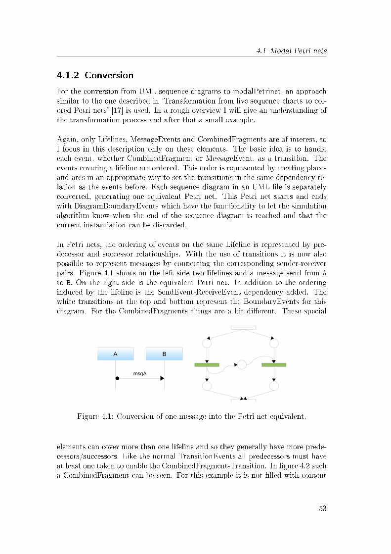
4.1 Modal Petri nets
4.1.2 Conversion
For the conversion from UML sequence diagrams to modalPetrinet, an approachsimilar to the one described in 'Transformation from live sequence charts to col-ored Petri nets' [17] is used. In a rough overview I will give an understanding ofthe transformation process and after that a small example.
Again, only Lifelines, MessageEvents and CombinedFragments are of interest, soI focus in this description only on these elements. The basic idea is to handleeach event, whether CombinedFragment or MessageEvent, as a transition. Theevents covering a lifeline are ordered. This order is represented by creating placesand arcs in an appropriate way to set the transitions in the same dependency re-lation as the events before. Each sequence diagram in an UML �le is separatelyconverted, generating one equivalent Petri net. This Petri net starts and endswith DiagramBoundaryEvents which have the functionality to let the simulationalgorithm know when the end of the sequence diagram is reached and that thecurrent instantiation can be discarded.
In Petri nets, the ordering of events on the same Lifeline is represented by pre-decessor and successor relationships. With the use of transitions it is now alsopossible to represent messages by connecting the corresponding sender-receiverpairs. Figure 4.1 shows on the left side two lifelines and a message send from A
to B. On the right side is the equivalent Petri net. In addition to the orderinginduced by the lifeline is the SendEvent-ReceiveEvent dependency added. Thewhite transitions at the top and bottom represent the BoundaryEvents for thisdiagram. For the CombinedFragments things are a bit di�erent. These special
Figure 4.1: Conversion of one message into the Petri net equivalent.
elements can cover more than one lifeline and so they generally have more prede-cessors/successors. Like the normal TransitionEvents all predecessors must haveat least one token to enable the CombinedFragment-Transition. In �gure 4.2 sucha CombinedFragment can be seen. For this example it is not �lled with content
53
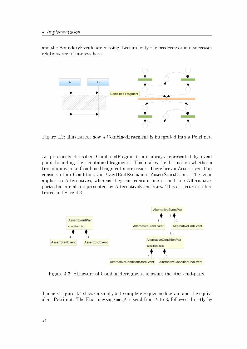
4 Implementation
and the BoundaryEvents are missing, because only the predecessor and successorrelations are of interest here.
Figure 4.2: Illustration how a CombinedFragment is integrated into a Petri net.
As previously described CombinedFragments are always represented by eventpairs, bounding their contained fragments. This makes the distinction whether atransition is in an CombinedFragment more easier. Therefore an AssertEventPairconsists of an Condition, an AssertEndEvent and AssertStartEvent. The sameapplies to Alternatives, whereas they can contain one or multiple Alternative-parts that are also represented by AlternativeEventPairs. This structure is illus-trated in �gure 4.3.
Figure 4.3: Structure of CombinedFragments showing the start-end-pairs.
The next �gure 4.4 shows a small, but complete sequence diagram and the equiv-alent Petri net. The First message msgA is send from A to B, followed directly by
54
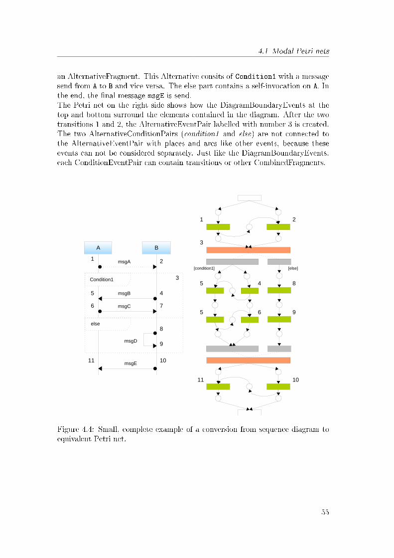
4.1 Modal Petri nets
an AlternativeFragment. This Alternative consits of Condition1 with a messagesend from A to B and vice versa. The else part contains a self-invocation on A. Inthe end, the �nal message msgE is send.The Petri net on the right side shows how the DiagramBoundaryEvents at thetop and bottom surround the elements contained in the diagram. After the twotransitions 1 and 2, the AlternativeEventPair labelled with number 3 is created.The two AlternativeConditionPairs (condition1 and else) are not connected tothe AlternativeEventPair with places and arcs like other events, because theseevents can not be considered separately. Just like the DiagramBoundaryEvents,each ConditionEventPair can contain transitions or other CombinedFragments.
Figure 4.4: Small, complete example of a conversion from sequence diagram toequivalent Petri net.
55

4 Implementation
4.2 Simulator components
The simulation is distributed on three eclipse plugins (dependencies are not listedhere).
• de.upb.swt.msdsimulation.petrinet.modal: Contains the model forthe SimulationPN and all generated interfaces and modi�ed implementa-tions
• de.upb.swt.scenarios.simulationextension: This is the heart of thesimulation and currently contains the observer for the play-out, Menu-Extensions, the sequence diagram to petrinet converter, violations and theplay-out strategies.
• org.pnml.core: The original petrinet model in form of an ecore �le takenfrom pnml.org. All other �les are generated with EMF and have not beenmodi�ed.
The core component is the PetrinetSimulationObserver which is instantiated afterthe conversion process of the UML �le to one or more simulationPNs. Now Iexplain the functions of the BindingManager, PoolManager, PlayoutStrategy(s),and how the observer operates.
BindingManager: This class is responsible for all ActivePNCon�gurations. Ev-erytime the Observer detects a minimal event and a new ActivePNCon�g-uration is created, this class stores them in an easy way to access them.With references similar to a hashmap, it is possible to get fast access to allActivePNCon�gurations that are currently bound to a speci�c EObject. Aschematic of this class is shown in �gure 4.5.
PoolManager: All converted SimulationPNs are stored in this class along withadditional information like participant count. The mapping of minimalevent to their occurring SimulationPNs is realized similar to the mappingin the BindingManager. A schematic diagram for the PoolManager can beseen in 4.6.
PlayoutStrategy: The interface PlayoutStrategy is used to chose the next avail-able message/event. Currently only one strategy is implemented, the Ran-domBestPlayoutStrategy. This strategy sorts the available messages into vi-olation categories (NoViolation, ColdViolation, HotViolation) and choosesone message randomly from the preferred NoViolation category. If thatcategory contains no messages, the category ColdViolation is used and afterthat from the HotViolation category. There also exists a PlayoutStrategyManager,which is a collection for all created strategies.
56

4.2 Simulator components
Figure 4.5: BindingManager schematic Figure 4.6: PoolManager schematic
Observer: The Observer combines all the previously mentioned classes from themodalPetrinet metamodel plus the Binding-, Pool- and PlayoutStrategy-Manager. It is the core of the simulation and responsible for the execu-tion of tasks like evaluating conditions. The activity diagram 4.7 gives anoverview of this process. The primary and only public method of the ob-server is triggerEvent which is invoked from the simulation menu. Theparameters are messagename, sender and receiver. With these informationthe observer queries the PoolManager for all SimulationPN that are linkedto this minimal event. Then for each of these SimulationPN an ActivePN-Con�guration is created and registered at the BindingManager. The senderand receiver EObjects are immediately bound to the appropriate Partici-pants. If the binding is complete, the next step is to �re the message.After this initialization phase, the simulation enters a loop until no moremessages are available. First, all available non-message events are executedlike AlternativeEventPairs and AssertEventPairs. Then a PlayoutStrategyis requested from the PlayoutStrategyManager which returns a messagethat has to be executed next. If no more messages are available, the loopends at this point. Is the new message for some SimulationPN a minimalevent, all the associated ActivePNCon�gurations are created before themessage is �red. Now the loop starts over again with the execution of allnon-message events.
57

4 Implementation
Figure 4.7: Activity diagram showing the di�erent operations of the simulation.
58
5 Conclusions and Future Work
The goal of this bachelors thesis was to investigate how the discrete behavior of amechatronic system can be modeled with a scenario-based approach in the earlydevelopment stages. In addition to this a simulation of the speci�ed behaviorshould support the analysis of this system.
The development of mechatronic systems, especially self-optimizing systems, is achallenging task. Currently new methods and languages for the development ofthese systems are being researched by the CRC 614. In self-optimizing mecha-tronic systems not only the mechanical and electrical engineering is involved, butalso the domains software- and control engineering [8].For these systems, many aspects have to be speci�ed including structure, shape,functions, goals for self-optimization, and behavior. The techniques currentlyused for behavior speci�cation in the principle solution are not yet su�cient,since they cannot be formally analyzed. The formal analysis of system behavioris important in order to detect errors early in the development stages.
To model the interaction of the environment and system components indepen-dently for application scenarios, I used Modal Sequence Diagrams. Based on anexample, I showed how the scenario-based behavior speci�cation can be realized.For this example the Railcab, a novel transportation system, was chosen.
Several problems could be identi�ed during the modelling of the scenarios, thatrequired additional concepts for their modeling and simulation. The dynamic ob-ject system makes the binding of objects to lifelines more di�cult. This is becauseit is not possible to refer to a speci�c (static) object. To cope with this problem,I used modi�ed assert elements and Object Navigation Constraints. This allowsthe binding of lifelines depending on the current context. As a side e�ect, it isnow possible to access object attributes and references by using OCL queries.Due to the hierarchy induced by components and subcomponents, the behaviorspeci�cation becomes a challenging task. Issues how to to model the internals ofa component without creating inconsistencies with the higher level speci�cationsstill have to be solved. Therefore I made use of existing concepts [2] and addedideas that allow the re�ning of lifelines. Now it is possible to model re�nementdiagrams which preserve the relation to their high level diagrams. This solu-tion allows the simulation of high level components and the observation of theirinternal behavior. The editors used to create other MML models are already
59
5 Conclusions and Future Work
developed as eclipse plugins. It also proved di�cult to adapt existing simula-tion engines. Therefore I implemented a plugin that integrates with the existingeclipse modelling tools.
Not all of the above mentioned topics could be fully implemented in time. Somemissing LSC/MSD elements like loops and parallels have to be integrated intomy implementation. Also the assigning of values and references is incomplete.This restricts the current simulation procedure drastically, since no changes tothe model can be made. I showed in section 3.5 Object Re�nement how to usere�nement diagrams in a simulation. To use this concept, the according changesto the simulation routine must be made.
During the course of elaborating the concepts for playing-out the MSDs, someproblems I identi�ed that could not be resolved in the scope of this thesis. Thefollowing points are open to be investigated in future work.To increase the modelling possibilities for engineers, additional constructs or ele-ments could be added. MSD and LSCs allow the use of parallels, loops, and manymore. So it has to be investigated if these constructs in�uence the re�nementof diagrams and components. In addition to this is it also necessary to �nd acorresponding modal Petri net representation.
Is a formal speci�cation language used to model the behavior, the play-out ofsystem messages can be extended.there is a lot of non-determinism in the play-out of MSDs. So, the simulationalgorithm has to make a lot of choices. It may happen that the simulation leadsto a hot violation that could have been avoided by making another choice in thepast. A smart play-out [11] improves the simulation by creating a decision tree.It looks a limited number of steps ahead to avoid choices that lead to invalid pathon this tree. To be sure never to run into hot violations, the complete synthesisof the speci�cation is needed [21].Section 3.5 Hierarchical re�nement introduced two methods, object re�nementand lifeline re�nement. The lifeline re�nement replaces a lifeline in a high leveldiagram by a new created re�nement diagram. In this re�nement diagram is thebehavior of the sub-components modeled. Object re�nement is a relation betweenan object and multiple re�nement diagrams, each describing the internal behav-ior. For both techniques some questions still remain. It should be investigatedhow to handle cold and hot violations in such hierarchies [2], or how to separatethe play-out and the di�erentiation between simulation levels. It is yet unclearif these re�nement techniques can be integrated into my solution and which �tsbest into the development process.
There are also some additions that may improve my implementation and sup-port an engineer modelling scenarios. Visual representation of the messages send
60

between components and highlighting of diagram cuts could be integrated, likerealized in the play-engine. The current possibilities to in�uence the simulationare restricted to environment messages like mentioned in [10]. Here, it could beusefull to force the play-out to prefer some messages.
61

5 Conclusions and Future Work
62

A Scenario diagrams
Scenario: Enter switch
Figure A.1: 'Enter switch': First diagram for this scenario modelling a Railcabentering a switch and requesting entrance.
63
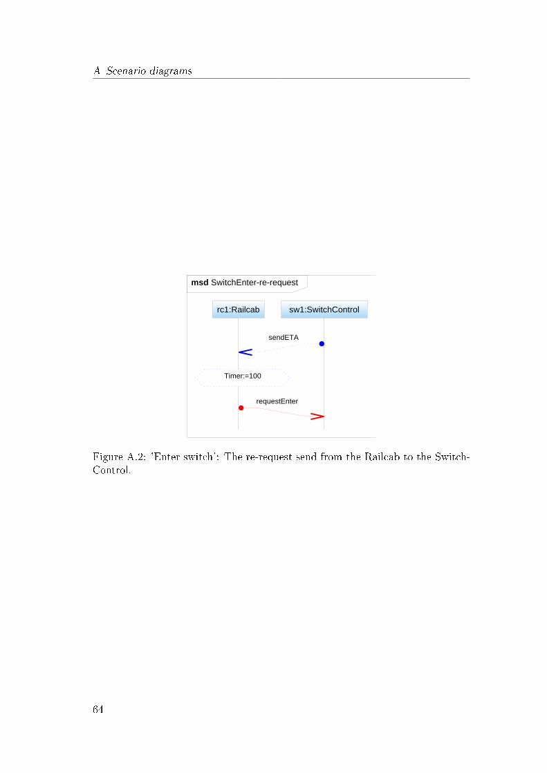
A Scenario diagrams
Figure A.2: 'Enter switch': The re-request send from the Railcab to the Switch-Control.
64

Scenario: Disband convoy
Figure A.3: 'Disband convoy': MSD showing the di�erent cases that have to bechecked for a separation from the convoy.
65

A Scenario diagrams
66

List of Figures
1.1 Two Railcabs autonomously formed a convoy to optimize theirenergy management. . . . . . . . . . . . . . . . . . . . . . . . . . 3
2.1 Hierarchy of MFM, AMS, and DMS . . . . . . . . . . . . . . . . . 62.2 VDI-Guideline 2206 'Design methodology for mechatronic systems'. 72.3 The four phases of the conception stage and their resulting docu-
ments. . . . . . . . . . . . . . . . . . . . . . . . . . . . . . . . . . 82.4 Principle solution overview showing the seven connected partial
models . . . . . . . . . . . . . . . . . . . . . . . . . . . . . . . . . 92.5 Basic UML sequence diagram . . . . . . . . . . . . . . . . . . . . 122.6 Live Sequence Diagram . . . . . . . . . . . . . . . . . . . . . . . . 142.7 Synchronization across Live Sequence Charts using the message
getNextTrackControl. . . . . . . . . . . . . . . . . . . . . . . . . . 152.8 Step 1: Message msgA forces two ActivePNCon�guration instan-
tiations. . . . . . . . . . . . . . . . . . . . . . . . . . . . . . . . . 162.9 Step 2: Message B is executed in both scenarios. . . . . . . . . . . 162.10 Step 3: Cold violation caused by msgC discards scenario2 and cre-
ates scenario3. . . . . . . . . . . . . . . . . . . . . . . . . . . . . . 172.11 After message requestEnter is received, the assert sc.trackIsFree
is evaluated. . . . . . . . . . . . . . . . . . . . . . . . . . . . . . . 172.12 Alternative used to model two di�erent traces, depending on the
isTrackFree boolean. . . . . . . . . . . . . . . . . . . . . . . . . . 182.13 AspectJ pointcut code snipplet. . . . . . . . . . . . . . . . . . . . 192.14 AspectJ advice code snipplet . . . . . . . . . . . . . . . . . . . . . 202.15 A screenshot showing the current development status of the Activestructure-
Editor. . . . . . . . . . . . . . . . . . . . . . . . . . . . . . . . . . 212.16 OCL code snipplet for simple condition checks. . . . . . . . . . . . 22
3.1 Track plan for this example . . . . . . . . . . . . . . . . . . . . . 243.2 Railcab metamodel created for this example . . . . . . . . . . . . 253.3 Some of the identi�ed scenarios and how they might overlap. . . . 263.4 'Railcab switches track': The datamodel before the scenario is
executed. . . . . . . . . . . . . . . . . . . . . . . . . . . . . . . . . 273.5 'Railcab switches track': Assumed MSD representing the behavior
of the 'main' or successfull trace. . . . . . . . . . . . . . . . . . . 28
67

List of Figures
3.6 'Railcab switches track': The datamodel after a successfull execu-tion of the main diagram. . . . . . . . . . . . . . . . . . . . . . . 29
3.7 'Railcab switches track': The two, small alternative endings to themain diagram. . . . . . . . . . . . . . . . . . . . . . . . . . . . . . 30
3.8 'Railcab switches track': Visualization of the di�erent endings forthe case of an 'track full' end. Cold violations discard the remain-ing two diagrams. . . . . . . . . . . . . . . . . . . . . . . . . . . . 30
3.9 'Detect track end': New, re�ned Active Structure of the Railcabshowing two subcomponents and the connected TrackControl. . . 31
3.10 'Detect track end': MSD from scenario 'Railcab switches track'that is used to re�ne the Railcab, indicated by the scenario nameabove it. . . . . . . . . . . . . . . . . . . . . . . . . . . . . . . . . 32
3.11 'Detect track end': Behavior of the internal components of theRailcab modeled in this re�nement diagram. . . . . . . . . . . . . 33
3.12 'Detect Railcab - create convoy': Simple message trace completedthrough an alternative fragment. . . . . . . . . . . . . . . . . . . . 34
3.13 Simple sequence diagram with assert CombinedFragment . . . . . 38
3.14 Result of the transformation process from MSD to Petri net . . . 38
3.15 Cut in a MSD and the equivalent Petri net cut, represented by theplaces (containing tokens). . . . . . . . . . . . . . . . . . . . . . . 40
3.16 On the left side a MSD with an alternative, on the right side theequivalent representation as a modal Petri net. . . . . . . . . . . . 41
3.17 Example of an assert fragment with OCL binding and the accord-ing part of the metamodel. . . . . . . . . . . . . . . . . . . . . . . 45
3.18 A potential hot violation is missed due to the late binding of tc2. 46
3.19 Possible external binding solution, the Object Navigation Con-straints, for scenario 'Railcab switches track'. . . . . . . . . . . . . 47
3.20 Assigning a new speed value of 400 to the railcab1. . . . . . . . 48
3.21 The MSD Railcab_decomp_1 is the re�nement diagram for theupper rc1:Railcab lifeline. . . . . . . . . . . . . . . . . . . . . . . 49
3.22 High level diagram and two sets of re�nement diagrams for Track-Control and Railcab. . . . . . . . . . . . . . . . . . . . . . . . . . 50
4.1 Conversion of one message into the Petri net equivalent. . . . . . 53
4.2 Illustration how a CombinedFragment is integrated into a Petri net. 54
4.3 Structure of CombinedFragments showing the start-end-pairs. . . 54
4.4 Small, complete example of a conversion from sequence diagramto equivalent Petri net. . . . . . . . . . . . . . . . . . . . . . . . . 55
4.5 BindingManager schematic . . . . . . . . . . . . . . . . . . . . . . 57
4.6 PoolManager schematic . . . . . . . . . . . . . . . . . . . . . . . . 57
4.7 Activity diagram showing the di�erent operations of the simulation. 58
68

List of Figures
A.1 'Enter switch': First diagram for this scenario modelling a Railcabentering a switch and requesting entrance. . . . . . . . . . . . . . 63
A.2 'Enter switch': The re-request send from the Railcab to the Switch-Control. . . . . . . . . . . . . . . . . . . . . . . . . . . . . . . . . 64
A.3 'Disband convoy': MSD showing the di�erent cases that have tobe checked for a separation from the convoy. . . . . . . . . . . . . 65
69

List of Figures
70

Bibliography
[1] Leonardo Amorim, Paulo Maciel, Meuse Nogueira, Raimundo Barreto, andEduardo Tavares. Mapping live sequence chart to coloured petri nets foranalysis and veri�cation of embedded systems. SIGSOFT Softw. Eng. Notes,31(3):1�25, 2006.
[2] Yoram Atir, David Harel, Asaf Kleinbort, and Shahar Maoz. Object com-position in scenario-based programming. In José Luiz Fiadeiro and PaolaInverardi, editors, FASE, volume 4961 of Lecture Notes in Computer Science,pages 301�316. Springer, 2008.
[3] Simona Bernardi, Susanna Donatelli, and José Merseguer. From uml se-quence diagrams and statecharts to analysable petri net models. In WOSP'02: Proceedings of the 3rd international workshop on Software and perfor-mance, pages 35�45, New York, NY, USA, 2002. ACM.
[4] Damm W. Klose J. Westphal B. Brill, M. and Wittke. Live sequence charts:An introduction to lines, arrows, and strange boxes in the context of formalveri�cation. Lecture Notes in Computer Science, 2004.
[5] Werner Damm and David Harel. Lscs: Breathing life into message sequencecharts. In Formal Methods in System Design, pages 293�312. Kluwer Aca-demic Publishers, 1999.
[6] Ursula Frank, Holger Giese, Florian Klein, Oliver Oberschelp, AndreasSchmidt, , Henner Vöcking, and Katrin Witting. Selbstoptimierende Sys-teme des Maschinenbaus � De�nitionen und Konzepte., volume 155 of HNI-Verlagsschriftenreihe, Paderborn. Heinz Nixdorf Institut, Universität Pader-born, Paderborn, 2004.
[7] Jürgen Gausemeier, Ursula Frank, Jörg Donoth, and Sascha Kahl. Spezi�ka-tionstechnik zur beschreibung der prinziplösung selbstoptimierender systemedes maschinenbaus. Konstruktion, Ausgabe 7/8-2008, 2008.
[8] Jürgen Gausemeier, Ursula Frank, and Bernd Schulz. Domänenübergreifendespezi�kation der prinziplösung selbstoptimierender systeme unter berück-sichtigung der auf das system wirkenden ein�üsse. In Mechatronik 2005 �Innovative Produktentwicklung, volume 1892.1 of VDI-Bericht, Düsseldorf,2005. Verein Deutscher Ingenieure.
71

Bibliography
[9] Jürgen Gausemeier, Ursula Frank, and Daniel Ste�en. Entwicklung selb-stoptimierender systeme. Konstruktion, VDI-Verlag, 10, 2005.
[10] David Harel, Asaf Kleinbort, and Shahar Maoz. S2a: A compiler for multi-modal uml sequence diagrams. In In FASE'07, pages 121�124, 2007.
[11] David Harel, Hillel Kugler, Rami Marelly, and Amir Pnueli. Smart play-outof behavioral requirements. Technical report, The Weizmann Institute ofScience, 2002.
[12] David Harel and Shahar Maoz. Assert and negate revisited: modal semanticsfor uml sequence diagrams. In SCESM '06: Proceedings of the 2006 interna-tional workshop on Scenarios and state machines: models, algorithms, andtools, pages 13�20, New York, NY, USA, 2006. ACM.
[13] David Harel, Shahar Maoz, David Harel, and Shahar Maoz. Modal semanticsfor uml sequence diagrams.
[14] David Harel and Rami Marelly. Come, Let's Play: Scenario-Based Program-ming Using LSCs and the Play-Engine. Springer, 1 edition, August 2003.
[15] C. Henke, C. Rustemeier, T. Schneider, J. Böcker, and A. Trächtler. Rail-cab - ein schienenverkehrssystem mit autonomen, linearmotor getriebe-nen einzelfahrzeugen. Internationaler ETG-Kongress 2007 - Kundennutzendurch neue Technologien in der Bahntechnik, Karlsruhe, Deutschland, 2007.
[16] Dipl. Inf, Olaf Kluge, Dr. Julia Padberg, Prof Dr, and Hartmut Ehrig. Mod-eling train control systems: From message sequence charts to petri nets,2000.
[17] Binsan Khadka and Boleslaw Mikolajczak. Transformation from live se-quence charts to colored petri nets. In SCSC: Proceedings of the 2007 sum-mer computer simulation conference, pages 673�680, San Diego, CA, USA,2007. Society for Computer Simulation International.
[18] Shahar Maoz and David Harel. From multi-modal scenarios to code: compil-ing lscs into aspectj. In SIGSOFT '06/FSE-14: Proceedings of the 14th ACMSIGSOFT international symposium on Foundations of software engineering,pages 219�230, New York, NY, USA, 2006. ACM.
[19] OMG Object Management Group (OMG). Uni�ed modeling language (uml)version 2.2.
[20] OMG Object Management Group (OMG). Xml metadata interchange, mof2.0/xmi mapping speci�cation. 2005.
72

Bibliography
[21] A. Pneuli and R. Rosner. Distributed reactive systems are hard to synthesize.In SFCS '90: Proceedings of the 31st Annual Symposium on Foundations ofComputer Science, pages 746�757 vol.2, Washington, DC, USA, 1990. IEEEComputer Society.
[22] VDI-Gesellschaft Entwicklung Konstruktion Vertrieb. Design methodologyfor mechatronic systems.
[23] Michael Wooldridge and Nicholas R. Jennings. Intelligent agents: Theoryand practice. Knowledge Engineering Review, 1994. Submitted to Revised.
73

Bibliography
74
Erklärung der Urheberschaft
Hiermit versichere ich, die vorliegende Bachelorarbeit ohne Hilfe Dritter und nurmit den angegebenen Quellen und Hilfsmitteln angefertigt zu haben. Alle Stellen,die aus den Quellen entnommen wurden, sind als solche kenntlich gemacht wor-den. Diese Arbeit hat in gleicher oder ähnlicher Form noch keiner Prüfungsbe-hörde vorgelegen.
Paderborn, den March 25, 2009 . . . . . . . . . . . . . . . . . . . . . . . . . . .Jens Frieben
75
