scope - home - my committeesmycommittees.api.org/standards/cre/scast/meeting... · web viewrwi...
TRANSCRIPT

DRAFT ----FOR COMMITTEE USE ONLY!Proposed Appendix E April 2004Printed 5/6/2023 7:18 AM Page 1
Proposed Revision APPENDIX E - SEISMIC DESIGN OF STORAGE TANKS
2005 Edition
Prepared by
Stephen W. Meier, PE SETank Industry Consultants
1234
123456789
1011121314151617181920212223242526272829303132333435363738394041424344
45

DRAFT ----FOR COMMITTEE USE ONLY!Proposed Appendix E April 2004Printed 5/6/2023 7:18 AM Page 2
PART I - PROVISIONS...............................................................................................................................................4
E.1 SCOPE....................................................................................................................................................................4
E.2 – DEFINITIONS AND NOTATIONS..................................................................................................................5
E.2.1 DEFINITIONS.......................................................................................................................................................5E.2.2 NOTATIONS........................................................................................................................................................5
E.3 PERFORMANCE BASIS......................................................................................................................................9
E.3.1 SEISMIC USE GROUP..........................................................................................................................................9E.3.1.1 Seismic Use Group III................................................................................................................................9E.3.1.2 Seismic Use Group II..................................................................................................................................9E.3.1.3 Seismic Use Group I...................................................................................................................................9E.3.1.4 Multiple use................................................................................................................................................9
E.4 SITE GROUND MOTION..................................................................................................................................9
E.4.1 MAPPED ASCE 7 METHOD................................................................................................................................9E.4.2 SITE-SPECIFIC SPECTRAL RESPONSE ACCELERATIONS....................................................................................10
E.4.2.1 Site-Specific Study....................................................................................................................................10E.4.2.2 Probabilistic Site-specific MCE Ground Motion.....................................................................................10E.4.2.3 Deterministic Site-specific MCE Ground Motion...................................................................................11E.4.2.4 Site-specific MCE Ground Motions..........................................................................................................11
E.4.3 SITES NOT DEFINED BY ASCE 7 METHODS....................................................................................................11E.4.4 MODIFICATIONS FOR SITE SOIL CONDITIONS..............................................................................................12 11 E.4.5 STRUCTURAL PERIOD OF VIBRATION..............................................................................................................15
E.4.5.1 Impulsive Natural Period.........................................................................................................................15E.4.5.2 Convective (Sloshing) Period...................................................................................................................16
E.4.6 DESIGN SPECTRAL RESPONSE ACCELERATIONS..............................................................................................17E.4.6.1 – Spectral Acceleration Coefficients........................................................................................................17
E.5 SEISMIC DESIGN FACTORS......................................................................................................................1819
E.5.1 – DESIGN FORCES........................................................................................................................................18 19 E.5.1.1 Response Modification Factor.................................................................................................................19E.5.1.2 Importance Factor....................................................................................................................................19
E.6 DESIGN.................................................................................................................................................................20
E.6.1 DESIGN LOADS.................................................................................................................................................20E.6.1.1 Effective Weight of Product..................................................................................................................2021E.6.1.2 Center of Action for Effective Lateral Forces..........................................................................................21E.6.1.3 Vertical Seismic Effects........................................................................................................................2223E.6.1.4 Dynamic Liquid Hoop Forces..................................................................................................................23E.6.1.5 Overturning Moment............................................................................................................................2425E.6.1.6 Soil-Structure Interaction.....................................................................................................................2526
E.6.2 RESISTANCE TO DESIGN LOADS..................................................................................................................25 26 E.6.2.1 Anchorage.............................................................................................................................................2526E.6.2.2 Maximum Longitudinal Shell Membrane Compression Stress............................................................2829E.6.2.3 Foundation...........................................................................................................................................3031E.6.2.4 Hoop Stresses.......................................................................................................................................3132
E.7 DETAILING REQUIREMENTS...................................................................................................................3132
E.7.1 ANCHORAGE................................................................................................................................................31 32 E.7.1.1 Self-anchored........................................................................................................................................3132E.7.1.2 Mechanically-anchored........................................................................................................................3132
1234
1
2
3
45
6
789
1011
12
13141516171819202122232425
26
272829
30
313233343536373839404142
43
444546

DRAFT ----FOR COMMITTEE USE ONLY!Proposed Appendix E April 2004Printed 5/6/2023 7:18 AM Page 3
E.7.2 FREEBOARD..................................................................................................................................................32 33 E.7.3 PIPING FLEXIBILITY.....................................................................................................................................33 34
E.7.3.1 – Method for Estimating Tank Uplift....................................................................................................3435E.7.4 CONNECTIONS..............................................................................................................................................34 35 E.7.5 INTERNAL COMPONENTS..............................................................................................................................34 36 E.7.6 SLIDING RESISTANCE...................................................................................................................................35 36 E.7.7 LOCAL SHEAR TRANSFER.............................................................................................................................35 37 E.7.8 CONNECTIONS WITH ADJACENT STRUCTURES.............................................................................................36 37 E.7.9 SHELL SUPPORT...........................................................................................................................................36 37 E.7.10 Repair, Modification or Reconstruction ........................................................................................................37
1234
123456789
1011

DRAFT ----FOR COMMITTEE USE ONLY!Proposed Appendix E April 2004Printed 5/6/2023 7:18 AM Page 4
Proposed RevisionAPPENDIX E - SEISMIC DESIGN OF STORAGE TANKS
Part I - Provisions
E.1 SCOPE
This appendix provides minimum requirements for the design of welded steel storage tanks that may be subject to seismic ground motion. These requirements represent accepted practice for application to welded steel flat-bottom tanks supported at grade.
The fundamental performance goal for seismic design in this Appendix is the protection of life and prevention of catastrophic collapse of the tank. Application of this standard does not imply that damage to the tank and related components will not occur during seismic events.
This Appendix is based on the allowable stress design (ASD) methods with the specific load combinations given herein. Application of load combinations from other design documents or codes is not recommended, and may require the design methods in this Appendix be modified to produce practical, realistic solutions. The methods use an equivalent lateral force analysis that applies equivalent static lateral forces to a linear mathematical model of the tank based on a rigid wall, fixed based model.
The ground motion requirements in this Appendix are derived from ASCE 7 which is based on a maximum considered earthquake ground motion defined as the motion due to an event with a 2% probability of exceedance within a 50 year period (a recurrence interval of approximately 2500 years). Application of these provisions as written is deemed to meet the intent and requirements of ASCE 7. Accepted techniques for applying these provisions in regions or jurisdictions where the regulatory requirements differ from ASCE 7 are also included.
The pseudo-dynamic design procedures contained in this Appendix are based on response spectra analysis methods and consider two response modes of the tank and its contents- impulsive and convective. Dynamic analysis is not required nor included within the scope of this Appendix. The equivalent lateral seismic force and overturning moment applied to the shell as a result of the response of the masses to lateral ground motion are determined. Provisions are included to assure stability of the tank shell with respect to overturning and to resist buckling of the tank shell as a result of longitudinal compression.
The design procedures contained in this appendix are based on a 5% damped response spectra for the impulsive mode and 0.5% damped spectra for the convective mode supported at grade with adjustments for site specific soil characteristics. Application to tanks supported on a framework elevated above grade is beyond the scope of this Appendix. Seismic design of floating roofs is beyond the scope of this Appendix.
Optional design procedures are included for the consideration of the increased damping and increase in natural period of vibration due to soil-structure interaction for mechanically anchored tanks.
1234
1234
5
6
789
101112
131415161718
192021222324
25262728293031
3233343536
373839

DRAFT ----FOR COMMITTEE USE ONLY!Proposed Appendix E April 2004Printed 5/6/2023 7:18 AM Page 5
Tanks located in regions where S1 is less than or equal to 0.04 and SS less than or equal to 0.15, or the peak ground acceleration for the ground motion defined by the regulatory requirements is less than or equal to 0.05g, need not be designed for seismic forces; however, in these regions, tanks in SUG III shall comply with the freeboard requirements of this Appendix.“Dynamic analysis methods incorporating fluid-structure and soil-structure interaction are permitted to be used in lieu of the procedures contained in this Appendix with Purchaser approval and provided the design and construction details are as safe as otherwise provided in this Appendix .
E.2 – DEFINITIONS and NOTATIONS
E.2.1 Definitions
ACTIVE FAULT: A fault for which there is an average historic slip rate of 1 mm per year or more and geologic evidence of seismic activity within Holocene times (past 11,000 years).
CHARACTERISTIC EARTHQUAKE: An earthquake assessed for an active fault having a magnitude equal to the best-estimate of the maximum magnitude capable of occurring on the fault, but not less than the largest magnitude that has occurred historically on the fault.
MAXIMUM CONSIDERED EARTHQUAKE (MCE): The most severe earthquake ground motion considered in this Appendix
MECHANICALLY-ANCHORED TANK: Tanks that have anchor bolts, straps or other mechanical devices to anchor the tank to the foundation.
SELF-ANCHORED TANK: Tanks that use the inherent stability of the self-weight of the tank and the stored product to resist overturning forces.
SITE CLASS: A classification assigned to a site based on the types of soils present and their engineering properties as defined in this Appendix.
E.2.2 Notations
A lLateral acceleration coefficient, %g
Ai Impulsive design response spectrum acceleration coefficient, %g
Ac Convective design response spectrum acceleration coefficient, %g
Av Vertical earthquake acceleration coefficient, % g
Ci Coefficient for determining impulsive period of tank system
dc Total thickness (100 - ds) of cohesive soil layers in the top 30 m (100 ft).
di Thickness of any soil layer i (between 0 and30 m [100 ft]).
ds Total thickness of cohesionless soil layers in the top 30 m (100 ft)
D Nominal tank diameter, m ( ft)
E Elastic Modulus of tank material, MPa (psi)
1234
123456789
1011
12
13
14151617181920212223242526
27
282930313233343536
37

DRAFT ----FOR COMMITTEE USE ONLY!Proposed Appendix E April 2004Printed 5/6/2023 7:18 AM Page 6
Fa Acceleration-based site coefficient (at 0.2 sec period).
Fc Allowable longitudinal shell membrane compression stress, MPa (psi)
Fv Velocity-based site coefficient (at 1.0 sec period).
Fy Minimum specified yield strength of bottom annulus, MPa,(psi)
g Acceleration due to gravity in consistent units. m/sec2 (ft/sec2)
G Specific gravity
Ge effective Effective specific gravity including vertical seismic effects = G(1-0.4Av)
H Maximum design product level, m (ft)
I Importance factor coefficient set by seismic use group
HS Thickness of soil, m (ft).
J Anchorage ratio
K Coefficient to adjust the spectral acceleration from 5% to 0.5% damping = 1.5 unless otherwise specified.
L Required minimum width of the bottom annulus measured from the inside of the shell m (ft)
Mrw pRingwall moment - Portion of the total overturning moment that acts at the base of the tank shell perimeter, N/m (ft-lb),
Ms sSlab moment (used for pile cap and pile cap design), Nm (ft-lb)
nA Number of equally spaced anchors around the tank circumference.
N Standard penetration resistance, ASTM D1536-84.
Average field standard penetration test for the top 30m (100 ft)).
Nch Average standard penetration of cohesionless soil layers for the top 30m (100 ft)
Ni Impulsive hoop membrane force in tank wall, N/mm (lbf/in)
Nc Convective hoop membrane force in tank wall, N/mm (lbf/in)
Nh Product hydrostatic membrane force, N/mm ( lbf/in)
PI Plasticity index, ASTM D4318-93.
PAB Anchor design load, N (lbf)
PA’ Anchorage attachment design load, N (lbf)
Q Scaling factor from the MCE to the design level spectral accelerations; equals 2/3 for ASCE 7
R Force reduction coefficient for strength level design methods
Rwi Force reduction factor for the impulsive mode using allowable stress design methods
Rwc Force reduction coefficient for the convective mode using allowable stress design methods
S0 Mapped, maximum considered earthquake, 5-percent-damped, spectral response acceleration parameter at a period of zero seconds (peak ground acceleration for a rigid structure), %g
S1 Mapped, maximum considered earthquake, 5-percent-damped, spectral response acceleration parameter at a period of one second, %g.
1234
123456
789
10111213141516171819
20
212223242526272829303132333435

DRAFT ----FOR COMMITTEE USE ONLY!Proposed Appendix E April 2004Printed 5/6/2023 7:18 AM Page 7
Sa The 5-percent-damped, design spectral response acceleration parameter at any period based on mapped, probabilistic procedures, %g.
Sa* The 5-percent-damped, design spectral response acceleration parameter at any period based on
site-specific procedures, %g.
Sa0* The 5-percent-damped, design spectral response acceleration parameter at zero period based on
site-specific procedures, %g
SDS The design, 5-percent-damped, spectral response acceleration parameter at short periods (T =0.2 seconds) based on ASCE 7 methods, %g.
SD1 The design, 5-percent-damped, spectral response acceleration parameter at one second based on the ASCE 7 methods, %g.
SP Design level peak ground acceleration parameter for sites not addressed by ASCE methods.
SS Mapped, maximum considered earthquake, 5-percent-damped, spectral response acceleration parameter at short periods (0.2 sec), %g.
su Undrained shear strength, ASTM D2166 or ASTM D2850.
su Average undrained shear strength in top 30m (100 ft).
t Thickness of the shell ring under consideration, mm (in)
ta Thickness of the bottom plate under the shell extending at least the distance ,L, from the inside of the shell, less corrosion allowance, mm (in)
tb Thickness of tank bottom less corrosion allowance, mm (in)
ts Thickness of bottom shell course less corrosion allowance, mm (in)
tu Equivalent uniform thickness of tank shell, mm (in)
T Natural period of vibration of the tank and contents, seconds
Ti Natural period of vibration for impulsive mode of behavior, seconds.
TC Natural period of the convective (sloshing) mode of behavior of the liquid, seconds
TL Regional-dependent transition period for longer period ground motion, seconds.
T0 0.2 FvS1 / FaSS
TS FvS1 / FaSS.
vs Average shear wave velocity at large strain levels for the soils beneath the foundation, m/s (ft/s).
Average shear wave velocity in top one 30m (100 ft), m/s (ft/s)
Vi Design base shear due to impulsive component from effective weight of tank and contents, N (lbf)
Vc Design base shear due to the convective component of the effective sloshing weight, N ( lbf).
V Total design base shear, N (lbf)
w Moisture content (in percent), ASTM D2216-92.
wa Force resisiting uplift in annular region, N/m, (lbf/ft)
wAB Calculated design uplift load on anchors per unit circumferential length, N (lbf)
1234
123456789
10111213141516171819202122232425262728
29
30313233343536

DRAFT ----FOR COMMITTEE USE ONLY!Proposed Appendix E April 2004Printed 5/6/2023 7:18 AM Page 8
wint Calculated design uplift due to product pressure per unit circumferential length, N/m (lbf/ft)
wL Resisting force of tank contents per foot of shell circumference that may be used to resist the shell overturning moment, N/m (lbf/ft)
wrs Roof load acting on the shell, including specified 10% of the specified snow load N/m (lbf/ft)
wt Tank and roof weight acting at base of shell, N/m ( lbf/ft)
Wc Effective convective (sloshing) portion of the liquid weight, N (lbf)
Weff Effective weight contributing to seismic response
Wf Weight of the tank floor, N (lbf)
Wfd Total weight of tank foundation, N (lbf)
Wg Weight of soil directly over tank foundation footing, N (lbf)
Wi Effective impulsive weight of the liquid, N (lbf)Wp Total weight of the tank contents based on the design specific gravity of the product, N
(lbf)
Wr Total weight of fixed tank roof including framing, knuckles, any permanent attachments and 10% of the roof specified snow load, N/m (lbf/ft)and participating snow weight, if specified, N (lbf)
Wrs Total Rroof load acting on the tank shell including the specified snow loads10% of the roof specified snow load, N/m (lbf)
Ws Total weight of tank shell and appurtenances, N (lbf)
T Total weight of tank shell, roof, framing, knuckles, product, bottom, attachments, appurtenances, participating snow load, if specified, and appurtenances, N (lbf)
Xc Height from the bottom of the tank shell to the center of action of lateral seismic force related to the convective liquid force for ringwall moment, m (ft)
Xi Height from the bottom of the tank shell to the center of action of the lateral seismic force related to the impulsive liquid force for ringwall moment, m (ft)
Xr Height from the tank of the tank shell to the roof and roof appurtenances center of gravity, m (ft)
Xs Height from the bottom of the tank shell to the shell’s center of gravity, m (ft)
Xis Height from the bottom of the tank shell to the center of action of the lateral seismic force related to the impulsive liquid force for the slab moment, m (ft)
Xcs Height from the bottom of the tank shell to the center of action of lateral seismic force related to the convective liquid force for the slab moment, m (ft)
Y Distance from liquid surface to analysis point, (positive down), m (ft)
yu Estimated uplift for self-anchored tank, mm (in)
c Maximum longitudinal shell compression stress, MPa (psi)
s Hoop stress in the shell due to impulsive and convective forces of the stored liquid, MPa (psi)
h Product hydrostatic hoop stress in the shell, Mpa (psi)
T Total combined hoop stress in the shell, MPa (psi)
Friction coefficient for tank sliding
1234
123456789
10111213
141516171819202122
23242526
2728
2930
313233
34353637

DRAFT ----FOR COMMITTEE USE ONLY!Proposed Appendix E April 2004Printed 5/6/2023 7:18 AM Page 9
Mass density of fluid, kg/m3 (lbm/in3)
E.3 PERFORMANCE BASIS
E.3.1 Seismic Use GroupThe Seismic Use Group (SUG) for the tank shall be specified by the purchaser. If it is not specified, the Seismic Use Group shall be assigned to be SUG I.
E.3.1.1 Seismic Use Group III Seismic Use Group III tanks are those providing necessary service to facilities that are essential for post-earthquake recovery and essential to the life and health of the public; or, tanks containing substantial quantities of hazardous substances that do not have adequate control to prevent public exposure.
E.3.1.2 Seismic Use Group II
Seismic Use Group II tanks are those storing material that may pose a substantial public hazard and lack secondary controls to prevent public exposure, or those tanks providing direct service to major facilities.
E.3.1.3 Seismic Use Group I
Seismic Use Group I tanks are those not assigned to Seismic Use Groups III or II.
E.3.1.4 Multiple use
Tanks serving multiple use facilities shall be assigned the classification of the use having the highest Seismic Use Group.
E.4 SITE GROUND MOTION Spectral lateral accelerations to be used for design may be based on either “mapped” seismic parameters (zones or contours), “site-specific” procedures, or probabilistic methods as defined by the design response spectra method contained in this Appendix. A method for regions outside the USA where ASCE 7 methods for defining the ground motion may not be applicable is also included.
A methodology for defining the design spectrum is given in the following sections.
E.4.1 Mapped ASCE 7 Method For sites located in the USA, or where the ASCE 7 method is the regulatory requirement, the maximum considered earthquake ground motion shall be defined as the motion due to an event with a 2% probability of exceedence within a 50 year period. The following definitions apply:
SS is the mapped, maximum considered earthquake, 5-percent-damped, spectral response acceleration parameter at short periods (0.2 seconds).
S1 is the mapped, maximum considered earthquake, 5-percent-damped, spectral response acceleration parameter at a period of 1 second.
1234
1
2
345
6789
10
11
121314
15
16
17
1819
2021222324252627
28293031
3233
3435

DRAFT ----FOR COMMITTEE USE ONLY!Proposed Appendix E April 2004Printed 5/6/2023 7:18 AM Page 10
S0 is the mapped, maximum considered earthquake, 5-percent-damped, spectral response acceleration parameter at zero seconds (usually referred to as the peak ground acceleration). Unless otherwise specified or determined, S0 shall be defined as 0.4SS
when using the mapped methods.
E.4.2 Site-specific Spectral Response Accelerations
The design method for a site-specific spectral response is based on the provisions of ASCE 7. Design using site-specific ground motions should be considered where any of the following apply:
The tank is located within 10 km (6 miles) of a known active fault. The structure is designed using base isolation or energy dissipation systems, which is
beyond the scope of this Appendix. The performance requirements desired by the owner or regulatory body exceed the goal
of this Appendix.
Site-specific determination of the ground motion is required when the tank is located on Site Class F type soils.
If design for an MCE site-specific ground motion is desired, or required, the site–specific study and response spectrum shall be provided by the Purchaser as defined this Section.
However, in no case shall the ordinates of the site-specific MCE response spectrum defined be less than 80% of the ordinates of the mapped MCE response spectra defined in this Appendix.
E.4.2.1 Site-Specific Study
A site-specific study shall account for the regional tectonic setting, geology, and seismicity. This includes the expected recurrence rates and maximum magnitudes of earthquakes on known faults and source zones, the characteristics of ground motion attenuation, near source effects, if any, on ground motions, and the effects of subsurface site conditions on ground motions. The study shall incorporate current scientific interpretations, including uncertainties, for models and parameter values for seismic sources and ground motions.
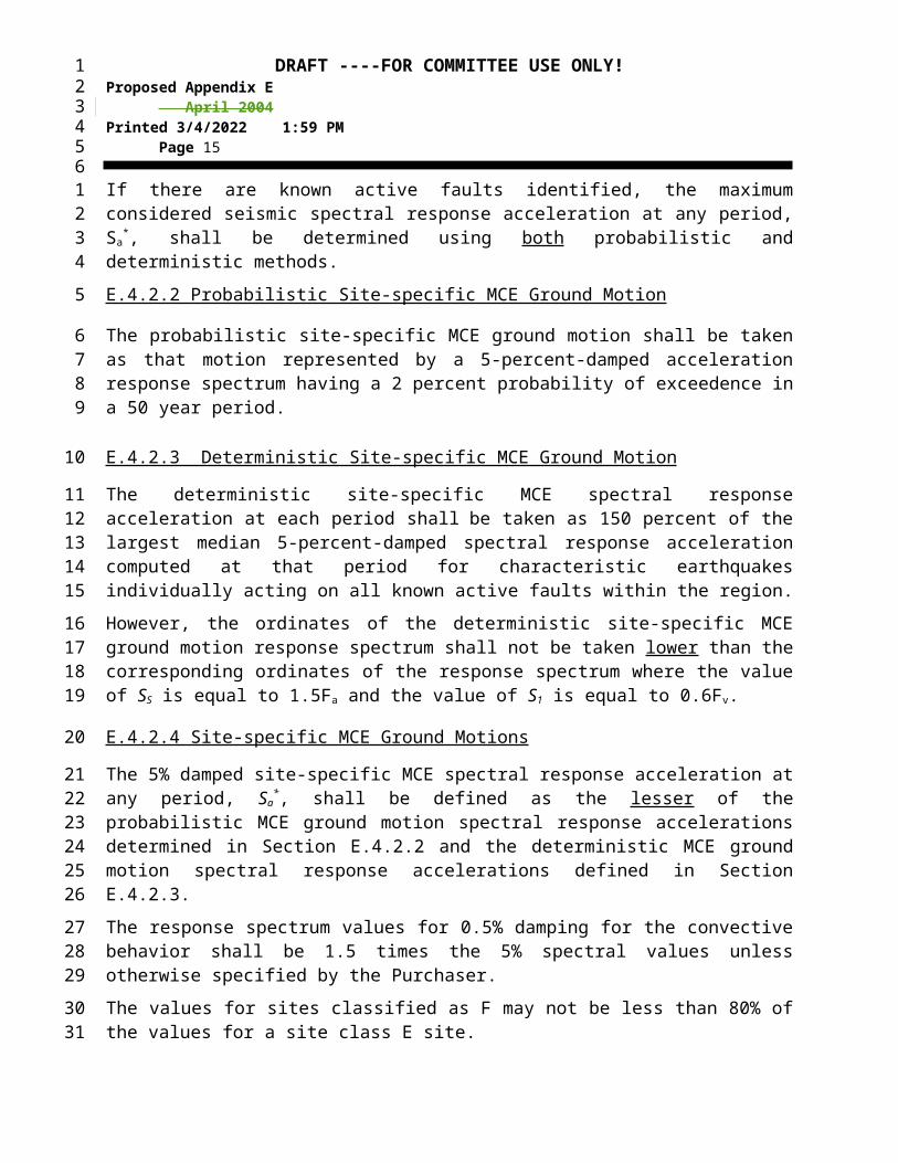
If there are known active faults identified, the maximum considered seismic spectral response acceleration at any period, Sa
*, shall be determined using both probabilistic and deterministic methods.
E.4.2.2 Probabilistic Site-specific MCE Ground Motion
The probabilistic site-specific MCE ground motion shall be taken as that motion represented by a 5-percent-damped acceleration response spectrum having a 2 percent probability of exceedence in a 50 year period.
E.4.2.3 Deterministic Site-specific MCE Ground Motion
The deterministic site-specific MCE spectral response acceleration at each period shall be taken as 150 percent of the largest median 5-percent-damped spectral response acceleration computed
1234
1234
5
6
789
1011121314
1516
1718
1920
21
222324252627
282930
31
323334
35
3637

DRAFT ----FOR COMMITTEE USE ONLY!Proposed Appendix E April 2004Printed 5/6/2023 7:18 AM Page 11
at that period for characteristic earthquakes individually acting on all known active faults within the region.
However, the ordinates of the deterministic site-specific MCE ground motion response spectrum shall not be taken lower than the corresponding ordinates of the response spectrum where the value of SS is equal to 1.5Fa and the value of S1 is equal to 0.6Fv.
E.4.2.4 Site-specific MCE Ground Motions
The 5% damped site-specific MCE spectral response acceleration at any period, Sa*, shall be
defined as the lesser of the probabilistic MCE ground motion spectral response accelerations determined in Section E.4.2.2 and the deterministic MCE ground motion spectral response accelerations defined in Section E.4.2.3.
The response spectrum values for 0.5% damping for the convective behavior shall be 1.5 times the 5% spectral values unless otherwise specified by the Purchaser.
The values for sites classified as F may not be less than 80% of the values for a site class E site.
E.4.3 Sites Not Defined by ASCE 7 Methods
In regions outside the USA, where the regulatory requirements for determining design ground motion differ from the ASCE 7 methods prescribed in this Appendix, the following methods may be utilized:
1. A response spectrum complying with the regulatory requirements may be used providing it is based on, or adjusted to, a basis of 5% and 0.5% damping as required in this Appendix. The values of the design spectral acceleration coefficients, Ai and Ac, which include the effects of site amplification, importance factor and response modification may be determined directly. Ai shall be based on the calculated impulsive period of the tank (see Section 4.6.1) using the 5% damped spectra, or the period may be assumed to be 0.2 seconds. Ac shall be based on the calculated convective period (see Section E.4.6.1) using the 0.5% spectra.
2. If no response spectra shape is prescribed and only the peak ground acceleration, SP, is defined, then the following substitutions shall apply:
Eqn (1)
Eqn (2)
E.4.4 Modifications for Site Soil Conditions The maximum considered earthquake spectral response accelerations for peak ground acceleration, shall be modified by the appropriate site coefficients, Fa and Fv from Tables E.4-A and E.4-B.
Where the soil properties are not known in sufficient detail to determine the site class, Site Class D shall be assumed unless the authority having jurisdiction determines that Site Class E or F
1234
12
345
6
789
10
1112
13
14
151617
1819202122232425
2627
2829
30
31323334
3536

DRAFT ----FOR COMMITTEE USE ONLY!Proposed Appendix E April 2004Printed 5/6/2023 7:18 AM Page 12
should apply at the site could apply at the site or in the event that Site Class E or F is established by geotechnical data.
Table E.4-A – Value of Fa as a Function of Site Class
Mapped Maximum Considered Earthquake Spectral Response Accelerations at Short Periods
Site Class Ss < 0.25 Ss =0.50 Ss = 0.75 Ss=1.0 Ss>1.25A 0.8 0.8 0.8 0.8 0.8B 1.0 1.0 1.0 1.0 1.0C 1.2 1.2 1.1 1.0 1.0D 1.6 1.4 1.2 1.1 1.0E 2.5 1.7 1.2 0.9 0.9F * * * * *
* Site Specific geotechnical investigation and dynamic site response analysis is required.
Table E.4-B - Value of Fv as a function of Site Class
Mapped Maximum Considered Earthquake Spectral Response Accelerations at 1 Sec Periods
Site Class S1 < 0.1 S1 = 0.2 S1 = 0.3 S1= 0.4 S1 > 0.5A 0.8 0.8 0.8 0.8 0.8B 1.0 1.0 1.0 1.0 1.0C 1.7 1.6 1.5 1.4 1.3D 2.4 2.0 1.8 1.6 1.5E 3.5 3.2 2.8 2.4 2.4F * * * * *
* Site Specific geotechnical investigation and dynamic site response analysis is required.
SITE CLASS DEFINTIONSThe Site Classes are defined as follows:
A Hard rock with measured shear wave velocity, vs > 1500 m/s (5,000 ft/sec) (1500 m/s)
B Rock with 760 m/s < vs 1500 m/s (2,500 ft/sec < vs 5,000 ft/sec) (760 m/s < vs 1500 m/s)
C Very dense soil and soft rock with 360 m/s < vs 760 m/s (1,200 ft/sec < vs 2,500 ft/sec) (360 m/s < vs
760 m/s) or with either > 50 or su > 100 kPa (2,000 psf) (100 kPa)
D Stiff soil with 180 m/s vs 360 m/s (600 ft/sec vs 1,200 ft/sec) (180 m/s vs 360 m/s) or with either 15 50 or 50 kPa su 100 kPa (1,000 psf su 2,000 psf) (50 kPa su 100 kPa)
E A soil profile with vs < 180 m/s (600 ft/sec) (180 m/s) or with either
< 15, su < 50 kPa (1,000 psf), or any profile with more than 3 m (10 ft) (3 m) of soft clay defined as soil with PI > 20, w 40 percent, and su < 25 kPa (500 psf) (25 kPa)
F Soils requiring site-specific evaluations:
1. Soils vulnerable to potential failure or collapse under seismic loading such as liquefiable soils, quick and highly sensitive clays, collapsible weakly cemented soils. However, since tanks typically have an impulsive period of 0.5 secs or less, site-specific evaluations are not required but recommended to determine spectral accelerations for liquefiable soils. The Site Class may be determined in accordance with Sec. E.4.7.2.2, assuming liquefaction does not occur, and the corresponding values of Fa and Fv determined from Tables
1234
12
3
4
5
6
78

DRAFT ----FOR COMMITTEE USE ONLY!Proposed Appendix E April 2004Printed 5/6/2023 7:18 AM Page 13
E.4-3 and E.4-4.
2. Peats and/or highly organic clays (HS > 3 m [10 ft] [3 m] of peat and/or highly organic clay, where H = thickness of soil)
3. Very high plasticity clays (HS> 8 m [25 ft] [8 m] with PI > 75)
4. Very thick, soft/medium stiff clays (HS > 36 m [120 ft] [36 m])
The parameters used to define the Site Class are based on the upper 30 m (100 ft) (30 m) of the site profile. Profiles containing distinctly different soil layers shall be subdivided into those layers designated by a number that ranges from 1 to n at the bottom where there are a total of n distinct layers in the upper 30 m (100 ft) (30 m). The symbol i then refers to any one of the layers between 1 and n.
where:
vsi = the shear wave velocity in ft/sec (m/s).
di = the thickness of any layer (between 0 and 30 m (100 ft) [30 m]).
(3.5-1)
where is equal to 30 m (100 ft) (30 m).
Ni = the Standard Penetration Resistance determined in accordance with ASTM D 1586, as directly measured in the field without corrections, and shall not be taken greater than 100 blows/ft.
(3.5-2)
(3.5-3)
where .
Use only di and Ni for cohesionless soils.
ds = the total thickness of cohesionless soil layers in the top 30 m (100 ft) (30 m).
sui = the undrained shear strength in psf (kPa), determined in accordance with ASTM D 2166 or D 2850, and shall not be taken greater than 240 kPa (5,000 psf) (240 kPa)..
(3.5-4)
where .
1234

DRAFT ----FOR COMMITTEE USE ONLY!Proposed Appendix E April 2004Printed 5/6/2023 7:18 AM Page 14
dc = the total thickness (100 - ds) of cohesive soil layers in the top 30 m (100 ft) (30 m).
PI = the plasticity index, determined in accordance with ASTM D 4318.
w = the moisture content in percent, determined in accordance with ASTM D 2216.
STEPS FOR CLASSIFYING A SITE:Step 1: Check for the four categories of Site Class F requiring site-specific evaluation. If the site corresponds to
any of these categories, classify the site as Site Class F and conduct a site-specific evaluation.
Step 2: Check for the existence of a total thickness of soft clay > 3 m (10 ft) (3 m) where a soft clay layer is defined by: su < 25 kPa (500 psf ) (25 kPa), w 40 percent, and PI > 20. If these criteria are satisfied, classify the site as Site Class E.
Step 3: Categorize the site using one of the following three methods with vs, and su computed in all cases see Table E.4-C:
a) vs for the top 30 m (100 ft) (30 m) (vs method)
b) for the top 30 m (100 ft ) (30 m) ( method)
c) for cohesionless soil layers (PI < 20) in the top 30 m (100 ft ) (30 m) and average su for cohesive soil layers (PI > 20) in the top 30 m (100 ft) (30 m) (su method)
Table E.4-C Site Classification
Site Class vs or sua
E( < 180 m/s)(< 600 fps)( < 180 m/s)
< 15< 50 kPa
(< 1,000 psf)( < 50 kPa)
D180 to 360 m/s
(600 to 1,200 fps)(180 to 360 m/s)
15 to 5050 to 100 kPa
(1,000 to 2,000 psf)(50 to 100 kPa)
C360 to 760 m/s
(1,200 to 2,500 fps)(360 to 760 m/s)
> 50 100 kPa
( > 2,000 psf)( > 100 kPa)
B760 m/s to 1500 m/s (2,500 to 5,000 fps)(760 m/s to 1500 m/s)
A > 1500 m/s (5,000 fps)(1500 m/s)
Note:a If the su method is used and the and su criteria differ, select the category with the
1234
12
DRAFT ----FOR COMMITTEE USE ONLY!Proposed Appendix E April 2004Printed 5/6/2023 7:18 AM Page 15
softer soils (for example, use Site Class E instead of D).
Assignment of Site Class B shall be based on the shear wave velocity for rock. For competent rock with moderate fracturing and weathering, estimation of this shear wave velocity shall be permitted. For more highly fractured and weathered rock, the shear wave velocity shall be directly measured or the site shall be assigned to Site Class C.
Assignment of Site Class A shall be supported by either shear wave velocity measurements on site or shear wave velocity measurements on profiles of the same rock type in the same formation with an equal or greater degree of weathering and fracturing. Where hard rock conditions are known to be continuous to a depth of 100 ft (30 m) (100 ft), surficial shear wave velocity measurements may be extrapolated to assess vs.
Site Classes A and B shall not be used where there is more than 3 m 10 ft (10 ft3 m) of soil between the rock surface and the bottom of the tank foundation.
E.4.5 Structural Period of VibrationThe pseudo-dynamic modal analysis method utilized in this Appendix is based on the natural period of the structure and contents as defined in this section.
E.4.5.1 Impulsive Natural Period The design methods in this Appendix are independent of impulsive period of the tank. However, the impulsive period of the tank system may be estimated by Eqn (3)
Eqn (3)
1234
1
2345
6789
10
1112
131415
16171819
20
2122

DRAFT ----FOR COMMITTEE USE ONLY!Proposed Appendix E April 2004Printed 5/6/2023 7:18 AM Page 16
FIgure E.4-1 Coefficient Ci
6
6.5
7
7.5
8
8.5
9
9.5
0 0.5 1 1.5
H/D
Ci
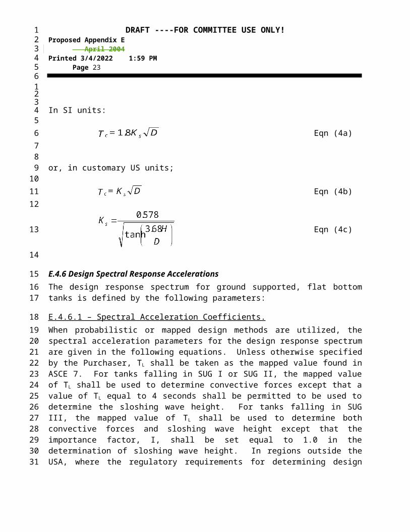
E.4.5.2 Convective (Sloshing) Period The first mode sloshing wave period, in seconds, shall be calculated by Equation (4) where Ks is the sloshing period coefficient defined in Eqn (4c):
In SI units:
Eqn (4a)
or, in customary US units;
Eqn (4b)
Eqn (4c)
1234
123456
789
101112131415161718192021
22
23

DRAFT ----FOR COMMITTEE USE ONLY!Proposed Appendix E April 2004Printed 5/6/2023 7:18 AM Page 17
E.4.6 Design Spectral Response AccelerationsThe design response spectrum for ground supported, flat bottom tanks is defined by the following parameters:
E.4.6.1 – Spectral Acceleration Coefficients. When probabilistic or mapped design methods are utilized, the spectral acceleration parameters for the design response spectrum are given in the following equations. Unless otherwise specified by the Purchaser, TL shall be taken as the mapped value found in ASCE 7. For tanks falling in SUG I or SUG II, the mapped value of TL shall be used to determine convective forces except that a value of TL equal to 4 seconds shall be permitted to be used to determine the sloshing wave height. For tanks falling in SUG III, the mapped value of TL shall be used to determine both convective forces and sloshing wave height except that the importance factor, I, shall be set equal to 1.0 in the determination of sloshing wave height. In regions outside the USA, where the regulatory requirements for determining design ground motion differ from the ASCE 7 methods prescribed in this Appendix, TL shall be taken as 4 seconds.
For sites where only the peak ground acceleration is defined, substitute SP for S0 in Eqns (5) thru (9). The scaling factor, Q, is defined as 2/3 for the ASCE 7 methods. Q may be taken equal to 1.0 unless otherwise defined in the regulatory requirements where ASCE 7 does not apply. Soil amplification coefficients, Fa and Fv; the value of the importance factor, I; and the ASD response modification factors, Rwi and Rwc, shall be as defined by the local regulatory requirements. If these values are not defined by the regulations, the values in this Appendix shall be used.
Impulsive spectral acceleration parameter, A i:
Eqn (5)
However, Eqn (6)and, for seismic design categories E and F only,
Eqn (7)
Convective spectral acceleration parameter, Ac:
When, TC < TL Eqn (8)
When, TC > TL , Eqn (9)
1234
123
456789
101112131415
161718192021222324
25
262728
29
303132
33
34

DRAFT ----FOR COMMITTEE USE ONLY!Proposed Appendix E April 2004Printed 5/6/2023 7:18 AM Page 18
E.4.6.2.1 Site Specific Response SpectraWhen site-specific design methods are specified, the seismic parameters shall be defined by Eqns (10) through (12).
Impulsive spectral acceleration parameter:
Eqn (10)
Alternatively, Ai, may be determined using either (1) the impulsive period of the tank system, or (2) assuming the impulsive period = 0.2 sec;
Eqn (11)
where, Sa* is the ordinate of the 5% damped, site-specific MCE response spectra at the
calculated impulsive period including site soil effects. See Section E.4.4.1.
Exception:Unless otherwise specified by the Purchaser, the value of the impulsive spectral acceleration, Sa*, for flat bottom tanks with H/D < 0.8 need not exceed 150%g when the tanks are:
self anchored, or mechanically anchored tanks that are equipped with traditional anchor bolt and chairs at
least 450 mm (18 inches in) high and are not otherwise prevented from sliding laterally at least 25 mm (1 inchin).
Convective spectral acceleration:
Eqn (12)
where, Sa* is the ordinate of the 5% damped, site-specific MCE response spectra at the calculated
convective period including site soil effects. See Section E.4.4.2.
Alternatively, the ordinate of a site-specific spectrum based on the procedures of E.4.2 for 0.5% damping may be used to determine the value Sa
* with K set equal to 1.0.
E.5 SEISMIC DESIGN FACTORS
E.5.1 – Design ForcesThe equivalent lateral seismic design force shall be determined by the general relationship
Eqn (13)where,
A = lateral acceleration coefficient, %gWeff = Effective weight
1234
123456
7
89
1011
12
13141516171819202122232425
26
2728293031
32
333435363738

DRAFT ----FOR COMMITTEE USE ONLY!Proposed Appendix E April 2004Printed 5/6/2023 7:18 AM Page 19
E.5.1.1 Response Modification Factor The response modification factor for ground supported, liquid storage tanks designed and detailed to these provisions shall be less than or equal to the values shown in Table E.5-A.
Table E.5-A, Response Modification Factors for ASD MethodsAnchorage system Rwi, (impulsive), Rwc, (convective)
Self – anchored 3.5 2Mechanically-anchored 4 2
E.5.1.2 Importance Factor The importance factor (I) is defined by the Seismic Use Group and shall be specified by the purchaser. See Section E.3 and Table E.5-B.
1234
123456
7
89
1011

DRAFT ----FOR COMMITTEE USE ONLY!Proposed Appendix E April 2004Printed 5/6/2023 7:18 AM Page 20
Table E.5-B - Importance Factor (I) and Seismic Use Group Classification
Seismic Use Group I
I 1.0
II 1.25
III 1.5
E.6 DESIGN
E.6.1 Design LoadsGround-supported, flat bottom tanks, storing liquids shall be designed to resist the seismic forces calculated by considering the effective mass and dynamic liquid pressures in determining the equivalent lateral forces and lateral force distribution. This is the default method for this Appendix. The equivalent lateral force base shear shall be determined as defined in the following sections.
The seismic base shear shall be defined as the square root of the sum of the squares (SRSS) combination of the impulsive and convective components unless the applicable regulations require direct sum. For the purposes of this Appendix, an alternate method using the direct sum of the effects in one direction combined with 40% of the effect in the orthogonal direction is deemed to be equivalent to the the SRSS summation.
Eqn (14)
Where, Eqn (15)
Eqn (16)
E.6.1.1 Effective Weight of Product The effective weights Wi and Wc shall be determined by multiplying the total product weight, Wp, by the ratios Wi/Wp and Wc/Wp, respectively, Equations (17) through (19).
When D/H is greater than or equal to 1.333, the effective impulsive weight is defined in Equation (17),
Eqn (17)
When D/H is less than 1.333, the effective impulsive weight is defined in Equation (18),
Eqn (18)
1234
12
3
456789
1011121314151617
18
19
202122
232425
26
2728
29

DRAFT ----FOR COMMITTEE USE ONLY!Proposed Appendix E April 2004Printed 5/6/2023 7:18 AM Page 21
The effective convective weight is defined in Equation (19),
Eqn (19)
E.6.1.2 Center of Action for Effective Lateral Forces The moment arm from the base of the tank to the center of action for the equivalent lateral forces from the liquid is defined by Equations (20) through (27).
The center of action for the impulsive lateral forces for the tank shell, roof and appurtenances is assumed to act through the center of gravity of the component.
E.6.1.2.1 Center of Action for Ringwall Overturning MomentThe ringwall moment, Mrw, is the portion of the total overturning moment that acts at the base of the tank shell perimeter. This moment is used to determine loads on a ringwall foundation, the tank anchorage forces, and to check the longitudinal shell compression.
The heights from the bottom of the tank shell to the center of action of the lateral seismic forces applied to Wi and Wc, Xi and Xc, may be determined by multiplying H by the ratios Xi /H and Xc
/H, respectively, obtained for the ratio D/H by using Equations (20) through ().
When D/H is greater than or equal to 1.3333, the height Xi is determined by Equation (20),
Eqn (20)
When D/H is less than 1.3333, the height Xi is determined by Equation (21),
Eqn (21)
The height Xc is determined by Equation (22),
Eqn (22)
1234
123
4
5
6789
1011
12131415161718192021222324252627
28
293031
32
34

DRAFT ----FOR COMMITTEE USE ONLY!Proposed Appendix E April 2004Printed 5/6/2023 7:18 AM Page 22
E.6.1.2.2 Center of Action for Slab Overturning MomentThe “slab” moment, Ms, is the total overturning moment acting across the entire tank base cross section. This overturning moment is used to design slab and pile cap foundations.
When D/H is greater than or equal to 1.3333, the height Xis is determined by Equation (23),
Eqn (23)
When D/H is less than 1.3333, the height Xis is determined by Equation (24),
Eqn (24)
The height, Xcs, is determined by Eqn (25):
Eqn (25)
E.6.1.3 Vertical Seismic Effects
When specified, vertical acceleration effects shall be considered as acting in both upward and downward directions and combined with lateral acceleration effects by the SRSS method unless a direct sum combination is required by the applicable regulations. Vertical acceleration effects for hydrodynamic hoop stresses shall be combined as shown in Section E.6.1.3.1. Vertical acceleration effects need not be combined concurrently for determining loads, forces and resistance to overturning in the tank shell.
The maximum vertical seismic acceleration parameter shall be taken as 0.14SDS or greater for the ASCE 7 method unless otherwise specified by the Purchaser. Alternatively, the Purchaser may specify the ertical ground motion acceleration parameter, Av. The total vertical seismic force shall be:
Eqn (26)
Vertical seismic effects shall be considered in the following when specified: Shell hoop tensile stresses (see Section E.6.1.4)
1234
123
45
6
789
10
111213
14
15
16
17
181920212223
24252627
2829
3031
DRAFT ----FOR COMMITTEE USE ONLY!Proposed Appendix E April 2004Printed 5/6/2023 7:18 AM Page 23
Shell membrane compression (see Section E.6.2.2) Anchorage design (see Section E.6.2.1) Fixed roof components Sliding Foundation design (see Section E.6.2.3)
In regions outside the USA where the regulatory requirements differ from the methods prescribed in this Appendix, the vertical acceleration parameter and combination with lateral effects may be applied as defined by the governing regulatory requirements.
E.6.1.4 Dynamic Liquid Hoop Forces Dynamic hoop tensile stresses due to the seismic motion of the liquid shall be determined by the following formulas:
For D/H 1.333:
In SI units:
Eqn (27a)
or, in customary US units;
Eqn (27b)
For D/H < 1.33 and Y < 0.75D:In SI units:
Eqn (28a)
or, in customary US units;
Eqn (28b)
For D/H < 1.333 and Y 0.75D:
In SI units:
Eqn (29a)
1234
123456
789
1011121314151617
18
1920
21
22232425
26
2728
29
303132333435363738

DRAFT ----FOR COMMITTEE USE ONLY!Proposed Appendix E April 2004Printed 5/6/2023 7:18 AM Page 24
or, in customary US units;Eqn (29b)
For all proportions of D/H:
In SI units:
Eqn (30a)
Eqn (30b)
1. When the Purchaser specifies that vertical acceleration need not be considered (i.e; Av=0), the combined hoop stress shall be defined by Eqn 31. The dynamic hoop tensile stress shall be directly combined with the product hydrostatic design stress in determining the total stress.
Eqn (31)
2. When vertical acceleration is specified.
Eqn (32)
E.6.1.5 Overturning Moment The seismic overturning moment at the base of the tank shell shall be the SRSS summation of the impulsive and convective components multiplied by the respective moment arms to the center of action of the forces unless otherwise specified.
Ringwall Moment, M rw:
Eqn (33)
1234
1234567
8
910
11
121314151617
18
192021
22
2324
2526272829303132

DRAFT ----FOR COMMITTEE USE ONLY!Proposed Appendix E April 2004Printed 5/6/2023 7:18 AM Page 25
Slab Moment, M s:
Eqn (34)
Unless a more rigorous determination is used, the overturning moment at the bottom of each shell ring shall be defined by linear approximation using the following:
1. If the tank is equipped with a fixed roof, the impulsive shear and overturning moment is applied at top of shell
2. The impulsive shear and overturning moment for each shell course is included based on the weight and centroid of each course.
3. The overturning moment due to the liquid is approximated by a linear variation that is equal to the ringwall moment, Mrw at the base of the shell to zero at the maximum liquid level.
E.6.1.6 Soil-Structure Interaction If specified by the Purchaser, the effects of soil-structure interaction on the effective damping and period of vibration may be considered for tanks in accordance with ASCE 7 with the following limitations:
Tanks shall be equipped with a reinforced concrete ringwall, mat or similar type foundation supported on grade. Soil structure interaction effects for tanks supported on granular berm, or pile type foundation are outside the scope of this Appendix.
The tanks shall be mechanically anchored to the foundation. The value of the base shear and overturning moments for the impulsive mode including
the effects of soil-structure interaction shall not be less than 80% of the values determined without consideration of soil-structure interaction.
The effective damping factor for the structure-foundation system shall not exceed 20%.
E.6.2 Resistance to Design LoadsThe allowable stress design (ASD) method is utilized in this Appendix. Allowable stresses in structural elements applicable to normal operating conditions may be increased by 33% when the effects of the design earthquake are included unless otherwise specified in this Appendix.
E.6.2.1 Anchorage Resistance to the design overturning (ringwall) moment at the base of the shell may be provided by:
the weight of the tank shell, weight of roof reaction on shell Wrs, and by the weight of a portion of the tank contents adjacent to the shell for unanchored tanks
mechanical anchorage devices.
E.6.2.1.1 Self-anchoredFor self-anchored tanks, a portion of the contents may be used to resist overturning. The anchorage provided is dependent on the assumed width of a bottom annulus uplifted by the
1234
123456789
101112131415
161718192021222324252627
28293031
323334353637
383940

DRAFT ----FOR COMMITTEE USE ONLY!Proposed Appendix E April 2004Printed 5/6/2023 7:18 AM Page 26
overturning moment. The resisting annulus may be a portion of the tank bottom (i.e. ta = tb) or a separate butt-welded annular ring (i.e. ta > tb). The resisting force of the annulus that lifts off the foundation shall be determined by Eqn (35)
In SI units:
196 HDGe Eqn (35a)
In customary US units 1.28 HDGe Eqn (35b)
Equation (35) for wa applies whether or not a thickened bottom annulus is used.
The tank is self-anchored providing the following conditions are met:1. The resisting force is adequate for tank stability (i.e. the anchorage ratio, J <
1.54).2. The maximum width of annulus for determining the resisting force is 3.5% of the
tank diameter.3. The shell compression satisfies section E.6.2.2.4. The required annular plate thickness does not exceed the thickness of the bottom
shell course.5. Piping flexibility requirements are satisfied.
E.6.2.1.1.1 Anchorage Ratio, J
Eqn (36)
Where:
Eqn (37)
Table E.6-A - Anchorage Ratio Criteria J
anchorage ratioCriteria
J < 0.785 No calculated uplift under the design seismic overturning moment. The tank is self anchored.
1234
123456789
101112131415161718192021222324
2526
27
28
29
3031323334353637

DRAFT ----FOR COMMITTEE USE ONLY!Proposed Appendix E April 2004Printed 5/6/2023 7:18 AM Page 27
0.785 < J <1.54 Tank is uplifting, but the tank is stable for the design load providing the shell compression requirements are satisfied. Tank is self-anchored.
J > 1.54 Tank is not stable and cannot be self-anchored for the design load. Modify the annular plate if L < 0.035D is not controlling or add mechanical anchorage.
E.6.2.1.1.2 Annular Plate Requirements The thickness of the tank floor plate provided under the shell may be greater than or equal to the thickness of the general tank floor plate (i.e. ta > tb) with the following restrictions. (Note- In thickening the bottom annulus, the intent is not to force a thickening of the lowest shell course, thereby inducing an abrupt thickness change in the shell, but rather to impose a limit on the bottom annulus thickness based on the shell design).
1. The thickness, ta, used to calculate wa in Equation (35) shall not exceed the first shell course thickness, ts, less the shell corrosion allowance,
2. Nor shall the thickness, ta, used in Equation (35) exceed the actual thickness of the plate under the shell less the corrosion allowance for tank bottom.
3. When the bottom plate under the shell is thicker than the remainder of the tank bottom (i.e. ta> tb) the minimum projection of the supplied thicker annular plate inside the tank wall, Ls, shall be equal to or greater than L:
In SI units:
Eqn (38a)
In customary US units
, 0.035D (ft) Eqn (38b)
E.6.2.1.2 Mechanically-anchored If the tank configuration is such that the self-anchored requirements can not be met, the tank must be anchored with mechanical devices such as anchor bolts or straps.When tanks are anchored, the resisting weight of the product shall not be used to reduce the calculated uplift load on the anchors. The anchors shall be sized to provide for at least the following minimum anchorage resistance, :
Eqn (39)
Plus 0.4 times the uplift, in N/m (lbf/ft2) of shell circumference, due to design internal pressure. See API 650 Section 3.12 for load combinations. If the ratio of operating pressure to design
1234
1
23456789
101112131415161718192021222324
2526272829303132
33
343536

DRAFT ----FOR COMMITTEE USE ONLY!Proposed Appendix E April 2004Printed 5/6/2023 7:18 AM Page 28
pressure exceeds 0.4, the purchaser should consider specifying a higher factor on design. Wind loading need not be considered in combination with seismic loading.
The anchor seismic design load, PAB, is defined in Eqn (40)
Eqn (40)
where, nA is the number of equally spaced anchors around the tank circumference. PAB shall be increased to account for unequal spacing.
When mechanical anchorage is required, the anchor embedment or attachment to the foundation, the anchor attachment assembly and the attachment to the shell shall be designed for PA., Tthe anchor attachment design load, PA, shall be the lesser of the load equal to the minimum specified yield strength multiplied by the as-built cross-sectional area of the anchor or three times PAB.
The maximum allowable stress for the anchorage parts shall not exceed the following values for anchors designed for the seismic loading alone or in combination with other load cases:
An allowable tensile stress for anchor bolts and straps equal to 80% of the published minimum yield stress.
For other parts, 133% of the allowable stress in accordance with Section 3.10.3. The maximum allowable design stress in the shell at the anchor attachment shall be
limited to 170 MPa (25,000 psi) with no increase for seismic loading. These stresses can be used in conjunction with other loads for seismic loading when the combined loading governs.
E.6.2.2 Maximum Longitudinal Shell Membrane Compression Stress
E.6.2.2.1 Shell Compression in Self-anchored Tanks The maximum longitudinal shell compression stress at the bottom of the shell when there is no calculated uplift, J < 0.785, shall be determined by the formula
In SI units:
Eqn(41a)
or, in customary US units;
Eqn (41b)
The maximum longitudinal shell compression stress at the bottom of the shell when there is calculated uplift, J > 0.785, shall be determined by the formula
1234
12345
6
78
9101112
1314151617181920212223
24
252627282930
31
3233
34
35363738

DRAFT ----FOR COMMITTEE USE ONLY!Proposed Appendix E April 2004Printed 5/6/2023 7:18 AM Page 29
In SI units:
Eqn (42a)
or, in customary US units;
Eqn (42b)
E.6.2.2.2 Shell Compression in Mechanically-anchored Tanks The maximum longitudinal shell compression stress at the bottom of the shell for mechanically-anchored tanks shall be determined by the formula
In SI units:
Eqn (43a)
or, in customary US units;
Eqn (43b)
E.6.2.2.3 Allowable Longitudinal Membrane Compression Stress in Tank ShellThe maximum longitudinal shell compression stress c must be less than the seismic allowable stress FC, which is determined by the following formulas and includes the 33% increase for ASD. These formulas for FC, consider the effect of internal pressure due to the liquid contents.
When GHD2/ t2 is greater than or equal to 44 (SI units) [106 U.S. Customary Units],
In SI units:FC = 83 ts / D Eqn (44a)
Or, in US Customary units:
FC = 106 ts / D Eqn (44b)
s
aavt
c tw
JwAw
121
18667.0607.04.01
3.2
s
aavt
c tw
JwAw
10001
18667.0607.0)4.01
3.2
s
rwvtc tD
MAw
10001273.1
4.01 2
1234
123
4
56
789
101112131415
161718
19
20212223242526272829303132333435

DRAFT ----FOR COMMITTEE USE ONLY!Proposed Appendix E April 2004Printed 5/6/2023 7:18 AM Page 30
In SI units:When GHD2/ t2 is less than 44,
FC = 83 ts / (2.5D) + 7.5 √( GH) <0.5Fty Eqn (45a)
Or, in customary US units;When GHD2I/t2 is less than 1x10⁶,
FC = 106 ts/ (2.5 D) + 600√( GH) < O.5 Fty Eqn (45b)
If the thickness of the bottom shell course calculated to resist the seismic overturning moment is greater than the thickness required for hydrostatic pressure, both excluding any corrosion allowance, then the calculated thickness of each upper shell course for hydrostatic pressure shall be increased in the same proportion, unless a special analysis is made to determine the seismic overturning moment and corresponding stresses at the bottom of each upper shell course (See Section E.6.1.5).
E.6.2.3 Foundation
Foundations and footings for mechanically-anchored flat-bottom tanks shall be proportioned to resist peak anchor uplift and overturning bearing pressure. Product and soil load directly over the ringwall and footing may be used to resist the maximum anchor uplift on the foundation, provided the ringwall and footing are designed to carry this eccentric loading.
Product load shall not be used to reduce the anchor load.
When vertical seismic accelerations are applicable, the product load directly over the ringwall and footing
1. When used to resist the maximum anchor uplift on the foundation, the product pressure shall be multiplied by a factor of (1-0.4Av) and the foundation ringwall and footing shall be designed to resist the eccentric loads with or without the vertical seismic accelerations.
2. When used to evaluate the bearing (downward) load, the product pressure over the ringwall shall be multiplied by a factor of (1+0.4Av) and the foundation ringwall and footing shall be designed to resist the eccentric loads with or without the vertical seismic accelerations.
The overturning stability ratio for mechanically-anchored tank system excluding vertical seismic effects shall be 2.0 or greater as defined in Eqn (46).
Eqn (46)
Ringwalls for self-anchored flat-bottom tanks shall be proportioned to resist overturning bearing pressure based on the maximum longitudinal shell compression force at the base of the shell in
1234
123456789
1011121314151617
18
19202122
23
2425
2627282930313233343536
37
383940

DRAFT ----FOR COMMITTEE USE ONLY!Proposed Appendix E April 2004Printed 5/6/2023 7:18 AM Page 31
Eqn (47). Slabs and pile caps for self-anchored tanks shall be designed for the peak loads determined in Section E.6.2.2.1.
Eqn (47)
E.6.2.4 Hoop Stresses The maximum allowable hoop tension membrane stress for the combination of hydrostatic product and dynamic membrane hoop effects shall be the lesser of:
The basic allowable membrane in this standard for the shell plate material increased by 33%; or,
0.9Fy times the joint efficiency where Fy is the lesser of the published minimum yield strength of the shell material or weld material.
E.7 DETAILING REQUIREMENTS
E.7.1 AnchorageTanks at grade are permitted to be designed without anchorage when they meet the requirements for self-anchored tanks in this appendix.
The following special detailing requirements shall apply to steel tank mechanical anchors in seismic regions where SDS > 0.05g.
E.7.1.1 Self-anchored For tanks in SUG III3 and located where SDS = 0.5g or greater, butt welded annular plates shall be required. Annular plates exceeding 10 mm (3/8 inch in.) thickness shall be butt-welded. The corner weld of the tank shell to bottom annular plate shall be checked for the design uplift load.
E.7.1.2 Mechanically-anchored
When mechanical-anchorage is required, at least six anchors shall be provided. The spacing between anchors shall not exceed 3 m (10 ft).
When anchor bolts are used, they shall have a minimum diameter of 25 mm (1 in.), excluding any corrosion allowance. Carbon steel anchor straps shall be 6 mm (¼ inch in.) minimum thickness and have a minimum corrosion allowance of 1.5 mm (1/16 in.)ch on each surface for a distance at least 75 mm (3 inchesin.) but not more than 300 mm (12 inchesin.) above the surface of the concrete.
Hooked anchor bolts (L or J shaped embedded bolts) or other anchorage systems based solely on bond or mechanical friction shall not be used when seismic design is required by this Appendix.
1234
1234
5
6
789
1011121314
15
161718
1920
21222324
25
2627
282930313233
3435

DRAFT ----FOR COMMITTEE USE ONLY!Proposed Appendix E April 2004Printed 5/6/2023 7:18 AM Page 32
Post-installed anchors may be used provided that testing validates their ability to develop yield load in the anchor under cyclic loads in cracked concrete and meet the requirements of ACI 355.
E.7.2 FreeboardSloshing of the liquid within the tank or vessel shall be considered in determining the freeboard required above the top capacity liquid level. A minimum freeboard shall be provided per Table E.7-A. See Section E.4.6.1. Purchaser shall specify whether freeboard is desired for SUG I tanks. Freeboard isrequired for SUG II and SUG III tanks. The height of the sloshing wave above the product design height can be estimated by:
Eqn (48)
For SUG I and II,
When, TC < 4 Eqn (49)
When, TC > 4 , Eqn (50)
For SUG III,
When, TC < TL Eqn (51)
When, TC > TL, Eqn (52)
TABLE E.7-A Minimum Required Freeboard Value of SDS SUG I SUG II SUG III SDS<0.33g 0.7s (a) 0.7s (a) s (c)SDS < 0.50g 0.7s (a) 0.7s (b) s (c)
a A freeboard of 0.7s is recommended for economic considerations but not required.b A freeboard equal to 0.7s is required unless one of the following alternatives are provided:
1. Secondary containment is provided to control the product spill.2. The roof and tank shell are designed to contain the sloshing liquid.
c Freeboard equal to the calculated wave height, s, is required unless one of the following alternatives are provided:
1. Secondary containment is provided to control the product spill.2. The roof and tank shell are designed to contain the sloshing liquid.
1234
12
345678
9
10
11
12
13
14
15
16
17
18
19
2021
22

DRAFT ----FOR COMMITTEE USE ONLY!Proposed Appendix E April 2004Printed 5/6/2023 7:18 AM Page 33
E.7.3 Piping FlexibilityPiping systems connected to tanks shall consider the potential movement of the connection points during earthquakes and provide sufficient flexibility to avoid release of the product by failure of the piping system. The piping system and supports shall be designed so as to not impart significant mechanical loading on the attachment to the tank shell. Local loads at piping connections shall be considered in the design of the tank shell. Mechanical devices which add flexibility such as bellows, expansion joints, and other flexible apparatus may be used when they are designed for seismic loads and displacements.
Unless otherwise calculated, piping systems shall provide for the minimum displacements in Table E.7-B at working stress levels (with the 33% increase for seismic loads) in the piping, supports and tank connection. The piping system and tank connection shall also be designed to tolerate 1.4Cd times the working stress displacements given in table E.7.B without rupture, although permanent deformations and inelastic behavior in the piping supports and tank shell is permitted. For attachment points located above the support or foundation elevation, the displacements in Table E.7-B shall be increased to account for drift of the tank or vessel.
Table E.7-B Design Displacements for Piping Attachments
ConditionASD Design
Displacementmm (in.)
Mechanically-anchored tanks
Upward vertical displacement relative to support or foundation:
Downward vertical displacement relative to support or foundation:
Range of horizontal displacement (radial and tangential) relative to support or foundation :
25 (1)
13 (0.5)
13 (0.5)
Self-anchored tanks
Upward vertical displacement relative to support or foundation:
Anchorage ratio less than or equal to 0.785:Anchorage ratio greater than 0.785:
Downward vertical displacement relative to support or foundation:
For tanks with a ringwall/mat foundation: For tanks with a berm foundation:
Range of horizontal displacement (radial and tangential) relative to support or foundation
25 (1)100 (4)
13 (0.5)25 (1)
50 (2)
The values given in Table E.7-B do not include the influence of relative movements of the foundation and piping anchorage points due to foundation movements (such as settlement or seismic displacements). The effects of foundation movements shall be included in the design of the piping system design, including the determination of the mechanical loading on the tank or vessel consideration of the total displacement capacity of the mechanical devices intended to add flexibility.
1234
1
23456789
10111213141516
17181920212223

DRAFT ----FOR COMMITTEE USE ONLY!Proposed Appendix E April 2004Printed 5/6/2023 7:18 AM Page 34
When SDS 0.1, the values in Table E.7-1 may be reduced to 70% of the values shown.
E.7.3.1 – Method for Estimating Tank Uplift The maximum uplift at the base of the tank shell for a self anchored tank constructed to the criteria for annular plates (see Section E.6.2.1) may be approximated by Eqn (53):
In SI units:
“later ”
Eqn(53a)
Or, in customary US units;
Eqn (53b)
E.7.4 ConnectionsConnections and attachments for anchorage and other lateral force resisting components shall be designed to develop the strength of the anchor (e.g., minimum published yield strength, Fy in direct tension, plastic bending moment), or times the calculated element design load.
Penetrations, manholes, and openings in shell components shall be designed to maintain the strength and stability of the shell to carry tensile and compressive membrane shell forces.
The bottom connection on an unanchored flat-bottom tank shall be located inside the shell a sufficient distance to minimize damage by uplift. As a minimum, the distance measured to the edge of the connection reinforcement shall be the width of the calculated unanchored bottom hold-down plus 300 mm (12 in.)
E.7.5 Internal Components
The attachments of internal equipment and accessories which are attached to the primary liquid or pressure retaining shell or bottom, or provide structural support for major components shall be designed for the lateral loads due to the sloshing liquid in addition to the inertial forces.
Seismic design of roof framing and columns shall be made if specified by the purchaser. The purchaser shall specify live loads and amount of vertical acceleration to be used in seismic design of the roof members. Columns shall be designed for lateral liquid inertia loads and acceleration as specified by the purchaser. Seismic beam-column design shall be based upon the primary member allowable stresses set forth in AISC (ASD), increased by one-third for seismic loading.
1234
1
23456789
10
11
1213141516
17
18192021
2223
24252627
28
293031
323334353637

DRAFT ----FOR COMMITTEE USE ONLY!Proposed Appendix E April 2004Printed 5/6/2023 7:18 AM Page 35
Internal columns shall be guided or supported to resist lateral loads (remain stable) even if the roof components are not specified to be designed for the seismic loads, including tanks that need not be designed for seismic ground motion in this Appendix (see Section E.1)
E.7.6 Sliding ResistanceThe transfer of the total lateral shear force between the tank and the subgrade shall be considered:
For self-anchored flat bottom steel tanks, the overall horizontal seismic shear force shall be resisted by friction between the tank bottom and the foundation or subgrade. Self-anchored storage tanks shall be proportioned such that the calculated seismic base shear, V, does not exceed Vs:
The friction coefficient, , shall not exceed 0.4. Lower values of the friction coefficient should be used if the interface of the bottom to supporting foundation does not justify the friction value above (e.g., leak detection membrane beneath the bottom with a lower friction factor, smooth bottoms, etc).
Eqn (54)
No additional lateral anchorage is required for mechanically-anchored steel tanks designed in accordance with this Appendix even though small movements of approximately 25 mm (1 inch in.) are possible.
The lateral shear transfer behavior for special tank configurations (e.g., shovel bottoms, highly crowned tank bottoms, tanks on grillage) can be unique and are beyond the scope of this Appendix.
E.7.7 Local shear transfer Local transfer of the shear from the roof to the shell and the shell of the tank into the base shall be considered. For cylindrical tanks, the peak local tangential shear per unit length shall be calculated by:
Eqn (55)
Tangential shear in flat bottom steel tanks shall be transferred through the welded connection to the steel bottom. The shear stress in the weld shall not exceed 80% of the weld or base metal yield stress. This transfer mechanism is deemed acceptable for steel tanks designed in accor-dance with the provisions and SDS < 1.0g.
E.7.8 Connections with Adjacent StructuresEquipment, piping, and walkways or other appurtenances attached to the tank or adjacent structures shall be designed to accommodate the elastic displacements of the tank imposed by design seismic forces amplified by a factor of 3.0 plus the amplified displacement of the other structure.
1234
123
456
789
10
11121314
151617181920
212223
24252627
28
29303132
3334353637

DRAFT ----FOR COMMITTEE USE ONLY!Proposed Appendix E April 2004Printed 5/6/2023 7:18 AM Page 36
E.7.9 Shell Support Self-anchored tanks resting on concrete ringwalls or slabs shall have a uniformly supported annulus under the shell. The foundation must be supplied to the tolerances required in Sec 5.5.5 in to provide the required uniform support for items b, c, and d below. Uniform support shall be provided by one of the following methods:a. Shimming and grouting the annulus,b. Using fiberboard or other suitable paddingc. Using double butt-welded bottom or annular plates resting directly on the foundation,
Annular plates or bottom plates under the shell may utilize back-up bars welds if the foundation is notched to prevent the back-up bar from bearing on the foundation.
d. Using closely spaced shims (without structural grout) provided that the localized bearing loads are considered in the tank wall and foundation to prevent local crippling and spalling.
Mechanically-anchored tanks shall be shimmed and grouted.
E.7.10 Repair, Modification or ReconstructionRepairs, modifications or reconstruction (i.e. cut down and re-erect) of a tank shall conform to industry standard practice, API653 and this Appendix. Tanks that are relocated shall be re-evaluated for the seismic loads for the new site and the requirements of new construction.
-end-
1234
123456789
1011121314
15161718
19