scv code - dgshipping.gov.lk · i scv code code of safety for small commercial vessels engaged in...
TRANSCRIPT
i
SCV CODE CODE OF SAFETY FOR SMALL COMMERCIAL VESSELS ENGAGED IN SRI LANKAN COASTAL WATERS
ii
Contents
CHAPTER I - GENERAL PROVISIONS 1
Part A - Application and Interpretation 1
1. Application 1 2. Categories of vessels 1 3. Definitions 2 4. Equivalence and exemptions 6 5. Approved equipment and material 6
Part B – Inspections 7
6. Extension of Inspection 7 7. Notice of inspection deficiencies and requirements 7 8. Unsafe practices 7 9. Hull and Tail shaft Examinations 7 10. Repairs, Alterations and Modifications 8 11. Additional tests and inspections 8
Part C – Certification 8
12. Application for a Certificate of survey 8 13. Certificate of survey 9 14. Description of Certificate 9 15. Posting of Certificates, Permits and Stability Letters 9 16. Special Permits 9
Part D – Passenger and Crew Capacity 10
17. Total Number of persons permitted 10
CHAPTER II – CONSTRUCTION 10
Part A - General Provisions 10
1. General Provisions 10 2. Plans and Information to be Submitted 10 3. Hull Structure 11 4. Means of Escape 11
Part B - Watertight and Weathertight Openings 12 5. Hatchways 12 6. Hatches which are open at sea 12 7. Doorways located above the weather deck 12 8. Companion hatch openings 13 9. Skylights 13 10. Portlights and Windows 13 11. Ventilators 14
Part C - Accommodation 14
12. General 14 13. Crew Spaces 15 14. Passenger Accommodation 15

iii
15. Passenger capacity 16 16. Water services 17 17. Galley 17 18. Toilet facilities 17 19. Stowage facilities for personal effects 17
Part D - Working Decks 17
20. Surface of Working Decks 17 21. Rails and Guards 17
CHAPTER III – FREEBOARD, STABILITY AND WATERTIGHT INTEGRITY 18
Part A – Freeboard 18
1. Minimum Freeboard 18 2. Loading Marks 18 3. Loading of a vessel 18
Part B – Stability 19
4. Stability Information for Operating Personnel 19 5. Stability Information 19 6. Intact stability requirements in general 19 7. Intact stability requirements for a sailing vessel 20 8. Simplified stability proof test procedure and assumptions 20 9. Installation of Ballast 23 10. Open Boats 23 11. Foam flotation material 23
Part C - Watertight Integrity 24
12. Drainage of Weather Decks 24 13. Air Pipes 24 14. Sea Inlets and Discharges 24 15. Materials for Valves and Associated Piping 25
Part D – Subdivision 25
16. Collision Bulkheads 25 17. Construction and Location of Collision Bulkheads 25 18. Watertight Subdivision Bulkheads 26 19. Subdivision of Cargo Vessels 26 20. Subdivision of Passenger Vessels 26 21. Location of Watertight Bulkheads for Subdivision 27
CHAPTER IV – MACHINERY 29
Part A - General Provisions 29
1. General requirements 29 2. Gasoline engines for propulsion 31 3. Ventilation of Spaces relating to Gasoline 32 4. Ventilation of spaces relating to diesel 33 5. Exhausts 34 6. Engine Starting 34 7. Portable Plant 34 8. Propulsion Engine Control Systems 34
iv
Part B - Steering and Propeller Systems 35 9. Main Steering Gear 35 10. Auxiliary Means of Steering 35 11. Propeller Systems 36
Part C - Bilge Systems 36
12. General Provisions for Bilge Systems 36 13. Bilge piping system 36 14. Bilge pumps 37 15. Bilge high level alarms 38
Part D - Electrical Arrangements 39
16. General Provisions 39 17. Power Sources 39 18. Electrical Systems 40 19. Cables and Wiring 41 20. Batteries 41 21. Battery Installation 41 22. General grounding requirements 42 23. Lighting 42 24. Hazardous Spaces 42
CHAPTER V - FIRE PROTECTION 43
Part A - General Provisions 43
1. Fire Protection Provisions 43 2. Machinery Space – Construction 43 3. Insulation 44 4. Cooking Appliances 44 5. Fire Safety 44
Part B - Fire Extinguishing and Detecting Equipment 45
6. Equipment installed but not required 45 7. Fire pumps 45 8. Fire main and hydrants 45 9. Fire hoses and nozzles 45 10. Requirement for Fixed Fire Extinguishing and Detecting Systems 46 11. Number, Type and location of Portable Fire Extinguishers 47 12. Fire axe 47 13. Fire bucket 48 14. Servicing of fixed and portable fire extinguishers 48 15. Fire Blanket 48
CHAPTER VI - LIFESAVING EQUIPMENT 48
1. General Provisions 48
2. Number and Type of Survival Craft 48 3. EPIRB, SART and Radar Reflector 49 4. Distress signals 49 5. Lifebuoys 49 6. Lifejackets 50 7. Stowage of survival craft 50 8. Special provisions for buoyant apparatus 51 8A Servicing of life saving appliances 52
8B Repair of inflatable survival craft 52
v
8C Record of repair and servicing 52 9. Survival craft equipment 53 10. Retro-reflective Material 53 11. Rescue and retrieval of persons from the water 53
CHAPTER VII - MISCELLANEOUS SYSTEMS AND EQUIPMENT 53
1. General Provisions 53
2. Navigation Lights, Shapes and Sound Signals 53 3. Charts and Nautical Publications 54 4. Navigation Equipment 54 5. Radio and Signaling Equipment 55 6. Public address systems 55 7. Mooring and Ground Tackle 56 8. First Aid Kit 56 9. Cooking and Heating 56 10. Pollution Prevention Equipment and Procedures 57
CHAPTER VIII - OPERATIONAL REQUIREMENTS 58
Part A - Operational Requirements 58
1. General Provisions 58 2. Marine Casualties 58 3. Logbook 58 4. Miscellaneous Operating Requirements 59 Part B - Preparations for Emergencies 59 5. Record of Passengers 59 6. Passenger Safety 60 7. Emergency Instructions 61 8. Recommended Emergency Instructions Format 61 9. Emergency Station Bill 62 10. Abandon Ship and Man Overboard Drills and Training 62 11. Fire Fighting Drills and Training 63 12. Markings Required 63 13. Operational Readiness, Maintenance and Inspection of Lifesaving Equipment 64 14. Instruction manuals, documentation, signs/notices and language used 64
CHAPTER IX - LICENCING OF BOATMASTERS AND ENGINEERS, MANNING AND
HOURS OF WORK 64
Part A – Licences 64
1. Boatmaster 64 2. Boat Engineer 64 2A Crew 65 3. License issue, standards and conditions 65 4. Grades and area restrictions of Boatmaster Licenses 66 5. Requirements for obtaining a Boatmaster License 66 6. Examination for Boatmaster Licenses 67 7. Grade and Area Restrictions of Boat Engineer Licenses 67 8. Requirements for obtaining a Boat Engineer License 68 9. Approved Course 68 10. Examination for Boat Engineer Licences 68

vi
11. Existing licences 68 12. Period of Validity and Renewal of License 69 13. Medical Fitness Certificate 69 14. Record and surrender of licenses 69
Part B - Hours of Work 69
15. Working Hours 69
Part C – Manning 70 16. Minimum Manning 70
CHAPTER X – AMENDMENTS TO THE SCV CODE 70
ANNEX 1
SPECIMEN OF CERTIFICATE OF SURVEY
ANNEX 2
SIMPLIFIED STABILITY TEST PROCEDURE
ANNEX 3
SMALL COMMERCIAL VESSEL SIMPLIFIED SUBDIVISION CALCULATION
ANNEX 4
FIRE TEST FOR FRP ANNEX 5
IGNITABILITY TEST FOR COMBUSTIBLE INSULATIONS
ANNEX 6
RECOMMENDED EMERGENCY BROADCAST INSTRUCTIONS
ANNEX 7
ANCHORS AND CABLES
ANNEX 8
FIRST AID KITS
ANNEX 9
ESTIMATING GUIDELINES FOR HOLDING TANK CAPACITY
ANNEX 10
SPECIMEN OF BOATMASTER AND BOAT ENGINEER LICENCE ANNEX 11 SYLLABUS FOR BOATMASTER AND BOAT ENGINEER LICENCES ANNEX 12 NAVIGATION AND COMMUNICATION EQUIPMENT REQUIREMENT
ANNEX 13
CASUALTY REPORTING FORMS

Page 1 of 74
CHAPTER I - GENERAL PROVISIONS
PART A - APPLICATION AND INTERPRETATION
1. Application The Code applies to
(a) commercial vessels, which are cargo, or passenger vessels of not less than 5m and not more
than 24m in length and which carry not more than 100 passengers or provide overnight
accommodation for not more than twenty four passengers engaged in coastal waters of Sri
Lanka; and
(b) pleasure vessels used for profit or reward.
2. Categories
2.1 Design categories
SCV Code
Design category
Wind force (Beaufort
scale)
Significant wave height
(H ⅓, metres)
ISO 12217 Design
Category
A
B
C
up to, and including, 8
up to, and including, 6
up to, and including, 4
up to, and including, 4
up to, and including, 2
up to, and including, 0,3
B
C
D
Design category-A
A vessel given design category A is considered to be designed for a wind force up to, and including,
8 and significant wave height up to, and including, 4 m.
Design category-B
A vessel design category B is considered to be designed for a wind force up to, and including, 6 and
significant wave height up to, and including, 2 m.
Design category-C
A vessel category C is considered to be designed for a wind force up to, and including, 4 and
significant wave height up to, and including, 0,3 m, with occasional waves of 0,5 m maximum
height.
Page 2 of 74
2.2 Vessel categories
Passenger vessel 1
Non passenger vessel 2
Pleasure vessels used for profit or reward 3
Work Boat 4
2.3 Areas of Operation
A vessel may be considered for the issue of a certificate of survey allowing it to operate in one or
more of the following operational areas:-
Protected water operation: operation an area of sheltered waters such as harbours, lagoons and rivers
which present no special hazards and within 3 nautical miles from a named port or place in
favourable weather. Sheltered waters between islands in Jaffna peninsula is considered as protected
waters.
This operational area is applied only for vessels of design categories of C and above.
Inshore water operation-1: operation within12 nautical miles from a named port or place in favorable
weather(for existing crafts) and the distance limitation shall indicate in the certificate of survey.
Note; existing vessels without proper structural assessment and/or designed details will be offered
operational areas Inshore water operation -1 only and the operational distance from a port or place
will be as same as the existing operational permit or similar document.
Inshore water operation-2: operation within 20 nautical miles from a safe haven. This operational
area is applied only for vessels of design categories of B and above.
Exposed water operation -1:operation within 20 nautical miles from a safe haven or not more than 12
nautical miles from the line of the coast in favourable weather. This operational area is applied only
for vessels of design categories of B and above.
Exposed water operation -2: operation within 20 nautical miles from a safe haven or not more than
20 nautical miles from the line of the coast. This operational area is applied only for vessels of design
categories of A and above.

Page 3 of 74
Unrestricted water operation in Sri Lankan waters: operation within 60 nautical miles from a safe
haven or operation not more than 20 nautical miles from the line of the coast engaged in voyages
between Sri Lankan ports or places. This operational area is applied only for vessels of design
categories of A and above.
Depending on the nature of the vessel and its use, a vessel may be restricted to less than the above
specified limits. Such a restriction should be recorded on the Certificate of the survey issued for the
vessel.
2.4 Vessel to be assigned an area of operation
(1) The Merchant Shipping Secretariat will assign the vessel an area of operation mentioned in the
above table according to its intended operations, equipments and design category.
Note 1 The owner of a vessel will inform the Merchant Shipping Secretariat in an application for a
certificate about the kind of vessel that it is, or is intended to be, and its intended operation area.
Note 2 The area of operation assigned to the vessel will be stated in the certificate of survey issued
by the Merchant Shipping Secretariat for the vessel.
3. Definitions
For the purpose of the Code, unless expressly provided otherwise -
.1 Accommodation space means any space other than machinery spaces, control spaces and
storerooms, used or accessible by passengers or crew including, but not limited to:
Hall; a. Dining room and messroom; b. Lounge or cafe; c. Public sales room; d. Overnight accommodation space; e. Barber shop or beauty parlor; f. Office or conference room; g. Washroom or toilet space; h. Medical treatment room or dispensary; or i. Game or hobby room.
.2 Merchant Shipping Secretariat means the Maritime Administration of Sri Lanka.
.3 Boatboatmaster means the individual having command of a small commercial vessel.
.4 Beam or B means the maximum width of a vessel measured from:
a. On wooden vessels from the outside of planking on one side to the outside of planking
on the other; and
b. On all other vessels from the outside of a frame on one side to the outside of a frame
on the other
Page 4 of 74
.5 Bulbous bow means a design of bow in which the forward underwater frames ahead of the forward perpendicular are swelled out at the forefoot into a bulbous formation.
.6 Bulkhead deck means the uppermost deck to which watertight bulkheads and the watertight shell extends
.7 Cargo space means a:
a. Cargo hold;
i. Refrigerated cargo space; or ii. A trunk leading to or from a space listed above.
.8 Cargo vessel means any vessel used in any commercial purposes other than carrying passengers.
.9 Cockpit vessel means a vessel with an exposed recess in the weather deck extending not more
than one-half of the length of the vessel measured over the weather deck. .10 Commercial vessel means a vessel in commercial use and includes passenger vessels .11 Crew includes every person, except boatmasters and pilots, employed or engaged in any
capacity on board a vessel; .12 Crew accommodation space means an accommodation space designated for the use of crew
members and which passengers are normally not allowed to occupy. .13 Draft means the vertical distance from the molded baseline of a vessel at mid length to the
waterline. .14 Employer, in relation to a boatmaster who has command of a vessel in the course of his
employment, means the person who employs that boatmaster in that employment;
.15 Existing vessel means a vessel that is not a new vessel and operating in Sri Lanka before
04.05.2017 or a vessel for which initial construction has begun before [04.05.2017] in Sri
Lanka.
.16 Ferry means a vessel that:
.17 operates only in protected waters has provisions only for deck passengers or vehicles, or both;
ndoperates on a short run on a scheduled service between two or more places.
.18 Favourable weather means wind, sea and visibility conditions which are deemed by the
boatmaster to be safe for a small vessel to operate within the limits applied to it; or, in any
other case means conditions existing throughout a voyage or excursion in which the effects
either individually or in combination of swell, height of waves, strength of wind and
visibilitycause no hazard to the safety of the vessel, including handling ability.
In making a judgement on favourable weather, the boatmaster should have due regard to
official weather forecasts for the service area of the vessel or to weather information for the
area which may be available from the Meteorological department or similar organisation;
.19 Fishing vessel means a vessel used or intended to be used for fishing for profit and does not
include vessels used for the carriage of passengers used for sport fishing.
.20 Flash point means the temperature at which a liquid gives off a flammable vapor when heated
using the Pensky-Martens Closed Cup Tester method.

Page 5 of 74
.21 Float-free launching or arrangement means that method of launching a survival craft whereby
the survival craft is automatically released and break free from a sinking vessel in such a
manner as to be ready for use by survivors.
.22 Flush deck vessel means a vessel with a continuous weather deck located at the uppermost
sheer line of the hull.
.23 Galley means a space containing appliances with cooking surfaces that may exceed 120ºC
(250ºF).
.24 Gross or net tonnage is the measurement of a vessel as determined to the satisfaction of the
Merchant Shipping Secretariat.
.25 Harbors or safe refuge means a port, inlet or other body of water normally sheltered from
heavy seas by land and in which a vessel can navigate and safely moor. The suitability of a
location as a harbor or safe refuge is as determined by the Merchant Shipping Secretariat.
.26 Inflatable survival craft or Inflatable lifejacket means one which depends upon non-rigid,
gas-filled chambers for buoyancy and which are normally kept deflated until ready for use.
.27 IMDG Code means the International Maritime Dangerous Goods Code published by the
International Maritime Organization.
.28 International voyage means a voyage between one country and a port outside
that country.
.29 Launching appliance means a device for transferring a survival craft, rescue boat or boat for
the recovery of a man overboard from its stowed position safely to the water. For a launching
appliance using a davit, the term includes davit, winch and falls.
.30 Length means length overall, the distance between the foreside of the foremost fixed
permanent structure and the after side of the aftermost permanent structure.
.31 LSA Code means the International Life-Saving Appliance (LSA) Code adopted by the
Maritime Safety Committee of the International Maritime Organization at its sixty-sixth
session by Resolution MSC.48 (66) as amended .32 Machinery space means a space including a trunk, alleyway, stairway or duct to such a space
that contains: i. propulsion machinery of any type;
ii. steam or internal combustion machinery;
iii. oil transfer equipment;
iv. electrical motors of more than 7.5 kW (10 hp);
v. cargo refrigeration equipment;
vi. one or more oil-fired boilers or heaters; or vii. electrical generating machinery.
.33 Major conversion means repairs, alterations or modifications that: -
(a) substantially alter the dimensions of a vessel;
Page 6 of 74
(b) substantially increase a vessel’s service life; or
(c) alter the functional aspects of a vessel
-
.34 Means of escape means a continuous and unobstructed route from any point in a vessel to an
embarkation station. A means of escape can be both vertical and horizontal, and may include
doorways, passageways, stair towers and public spaces. Cargo spaces, machinery spaces, rest
rooms, hazardous areas, escalators and elevators shall not form any part of a means of escape.
.35 New vessel means a vessel for which the initial construction began on or after [04.05.2017] or
a vessel, which has undergone repairs, alterations or modifications of a major character , as
identified in I/10.4 on or after this date.
.36 Non-self-propelled vessel means a vessel, which does not have a means of propulsion
installed, such as propulsive machinery, masts, spars or sails.
.37 Open boat means a vessel which is open to the elements and is not fitted with a complete
watertight or weather tight deck or complete structure above the waterline.
.38 Operating station means the principal steering station on the vessel from which the individual
on duty normally navigates the vessel.
.39 Overnight accommodation or overnight accommodation space means an accommodation
space for use by passengers or by crew members which has one or more berths, including
beds or bunks, for passengers or crew members to rest for extended periods. Overnight
accommodations do not include spaces, which contain only seats, including reclining seats.
.40 Passenger means any person carried in a vessel except a person employed or engaged in any
capacity on board the vessel or a child under one year of age.
.41 Passenger vessel means a vessel carrying more than 12 passengers and engaged in operation
more than 12 hours
.42 Piping system includes piping, associated fittings and valves.
.43 Pleasure vessel means-
a. .1 (a) any vessel which at the time it is being used is-
in the case of a vessel wholly owned by an individual or individuals, used only for the sport or pleasure of the owneror the immediate family or friends of the owner; or in the case of a vessel owned by a body corporate, one on which the persons are employees,
b. officers or shareholders of the body corporate, or their immediate family or friends;
and
on a voyage or excursion which is one for which the owner does not receive money for or in connection with operating the vessel or carrying any person, other than as a contribution to the direct expenses of the operation of the vessel incurred during the voyage or excursion; or
c. .2 any vessel wholly owned by or on behalf of a club formed for the purpose of sport
or pleasure which, at the time it is being used, is used only for the sport or pleasure of

Page 7 of 74
members of the club or their immediate family, and for the use of which any charges
levied are paid into club funds and applied for the general use of the club; and
d. .3 in the case of any vessel referred to in paragraphs (1) or (2), no other payments are made by or on behalf of the users of the vessel, other than by the owner;
e. and in this definition, “immediate family” means, in relation to an individual, the
husband or wife of the individual, and a relative of the individual or the relative’s husband or wife, “relative” means brother, sister, ancestor or lineal descendant, and “owner” includes charterer.
.44 Recognised Organisation means an organization which is a member of the International
Association of Classification Societies(IACS) and has been assessed by Sri Lanka and found to comply with the requirement of RO code and listed in the schedule II of the gazette notification no 1469/22 dated 31.10.2006.
.45 Recognised Standard means an internationally accepted specific standard recognised by the
Merchant Shipping Secretariat.
.46 Safe haven means a harbor or shelter of any kind which affords safe entry and protection
from the force of weather.
.47 Satisfaction of the Merchant Shipping Secretariat means in the case of where there are no
guidelines are provided the Director General of Merchant Shipping will apply the rules or
interpretations made by national or international standards, or standards developed by
experienced organizations for those cases, such as unified interpretations of the International
Association of Classification Societies (IACS) or ISO standards.
.48 Survival craft means a lifeboat, liferaft, buoyant apparatus or small boat carried aboard a
vessel.
.49 Stability Surveyor means an approved naval architect or any other design engineer who has
working experience of 5 years or more in the naval design field or other related field.
.50 Vessel includes any ship or boat or any other description of vessel capable of being navigated.
.51 Voyage includes an excursion.
.52 Watertight means designed and constructed to prevent the passage of water in any direction.
.53 Weather tightmeans that in any sea conditions water will not penetrate into the vessel.
.54 Well deck vessel means a vessel with a weather deck fitted with solid bulwarks that impede
the drainage of water over the sides or a vessel with an exposed recess in the weather deck
extending more than one-half of the length of the vessel measured over the weather deck. .55 Working day, in relation to any person to whom Chapter IX of this Code applies means any
period during which the person is on duty which is not followed by an interval for rest of not less than 10 hours.
.56 Workspace means a space, not normally occupied by a passenger, in which a crew member

Page 8 of 74
performs work and includes, but is not limited to, a galley, operating station or machinery space.
4 Equivalence and exemptions
4.1 Where the Code requires that a particular fitting, material, appliance or apparatus, or type thereof,
piece of equipment or machinery shall be fitted or carried in a vessel, or that any particular provision
shall be made, the Merchant Shipping Secretariat may permit any other fitting, material, appliance or
apparatus or type thereof, piece of equipment or machinery to be fitted or carried or other provision
to be made in that vessel where it is satisfied by trials or otherwise that the alternative is at least as
effective as that required by the Code.
4.2 The Merchant Shipping Secretariat may exempt any vessel or description of vessels which this
code applies from all or any of the provisions of the Code, as shall be specified in the exemption,
provided that the Merchant Shipping Secretariat is satisfied that compliance with such provision is
either impracticable or unreasonable in the case of that vessel or description of vessels. The
exemption may be issued on such terms, if any, as the Merchant Shipping Secretariat may specify
and subject to giving reasonable notice, alter or cancel any such exemption.
5 Approved equipment and material
Equipment and material that is required by the Code shall be of an approved type. The Merchant Shipping Secretariat(MSS) will accept equipment approvals granted by a Recognized Organization (RO) acting on behalf of the Merchant Shipping Secretariat of Sri Lanka or by the United States Coast Guard(USCG) ,Maritime Coast Guard Agency in UK(UKMCA) or Maritime administration of Japan provided, the approvals are fully in accordance with the recognized standards. The Administration will also accept equipment that has been approved under the European Union Marine Equipment Directive (MED) procedures or any other recognized standards such as Sri Lanka Standard organsiation and International Standard Organisation.
PART B - INSPECTIONS
6 Extension of Inspection
6.1 Inspections for certification are based on the information, specifications, drawings and
calculations available to the Merchant Shipping Secretariat.
6.2 The initial or renewal inspection will cover the following items: hull, machinery, electrical
equipment, lifesaving equipment, fire protection equipment, pressure vessels and boilers, steering
systems, miscellaneous equipment and systems, sanitation and operational practices including the
competence and composition of the crew.
6.3 In general, the scope of an annual inspection is the same as for the inspection for issue of a
certificate of survey but in less detail.
6.4 Initial and renewal inspections shall be carried out by surveyors of an approved recognized
organization on behalf of the Merchant Shipping Secretariat. Annual survey may be carried out by
government ship surveyors of the Merchant Shipping Secretariat (MSS).
6.5 Existing vessels shall undergo initial inspection prior to issue of the certificate of survey subject
to section II/3.2 and the inspection shall be carried out by surveyors of Merchant Shipping
Secretariat an approved recognized organization on behalf of the Merchant Shipping Secretariat.
Page 9 of 74
7 Notice of inspection deficiencies and requirements
During the inspection of a vessel, the attending surveyor will record any deficiencies. The surveyor
will provide a copy of these to the owner and discuss arrangements for rectification.
8 Unsafe practices
During the course of any inspection due regard shall be given to confirming that all unsafe practices
identified on board have been corrected. Examples of this include fire hazards by virtue of oily
residues, unguarded machinery and provision of any protective clothing or devices necessary for the
safety of the crew
9 Docking and In water Examinations
9.1 A minimum of two Docking Surveys are to be held in each five-year Special Survey period and
the maximum interval between successive Docking Surveys is not to exceed three years. One of the
two Docking Surveys required in each five-year period is to coincide with the Special Survey.
Consideration may be given in exceptional circumstances to an extension of the Docking Survey, not
exceeding three months, provided the interval between successive surveys does not exceed 36
months.
Merchant Shipping Secretariat may accept an In-water Survey in lieu of the intermediate docking
between Special Surveys required in a five year period on ships where suitable protection is applied
to the underwater portion of the hull. Interval between two examinations in drydock or on slipway
not to be exceed five years.
For passenger vessels ,bottom inspections are required on an annual basis. The interval between any
two successive bottom surveys of passenger vessels is in no case to exceed 15 months.
Merchant Shipping Secretariat may accept an in-water survey in lieu of the intermediate docking
surveys required in one-year period, provided the interval between two examinations in drydock or
on slipway does not exceed three years.
If the In-water Survey reveals damage or deterioration that requires early attention, the Surveyor may
require that the ship be dry-docked in order that a fuller survey can be undertaken and the necessary
work carried out
10 Repairs, Alterations and Modifications
10.1 Repairs or alterations to the hull, machinery or equipment, which affect the safety of the vessel
shall not be made without the approval of the Merchant Shipping Secretariat, except in an
emergency. Drawings or written specifications of proposed alterations should be submitted to the
Merchant Shipping Secretariat which may require that an inspection and test be carried out.
10.2 Safe working practices shall be observed in the planning and execution of any alterations,
repairs or other operations involving riveting, welding, burning or other fire producing actions aboard
a vessel particularly where these take place adjacent to fuel tanks or apparatus connected to the fuel
tanks.
10.3 Repairs, alterations and modifications of a major character and outfitting related thereto on existing vessels shall meet the requirements prescribed for a new vessel to such extent as the Merchant Shipping Secretariat deems reasonable and practicable. The owner shall inform the
Page 10 of 74
Merchant Shipping Secretariat of the proposed alterations and modifications before such alterations and modifications are carried out.
10.4 For the purpose of the Code, the following repairs, alterations and modifications shall be
recognized as being of "major character":
(a) any changes that substantially alter the dimensions of the vessel;
(b) any changes that substantially increase a vessel's service life; or
(c) any conversions that alter the functional aspects of the vessel.
11 Additional tests and inspections
The Merchant Shipping Secretariat may make inspections or tests of the vessel in addition to those
described above, as deemed necessary to determine that the vessel and its equipment are suitable for
the service in which they are to be employed.
11-A Maintenance of conditions after inspection
11.A.1 The condition of the vessel and is equipment shall be maintained to conform with the
provisions of the Code to ensure that the vessel in all respects will remain fit to proceed to sea
without damage to the vessels or persons on board.
11.A.1Where any vessel found to be operated contravening the condition as stated in section
I/11.A.1, will be detained until such conditions are rectified.
11.A.2 After any inspection of a vessel under I/13has been completed, no change shall be made in
the structural arrangements, machinery or other items covered by the survey without the approval of
the Merchant Shipping Secretariat.
11.A.3 Whenever an accident occurs to a vessel or a deficiency is discovered which affects the safety
of the vessel or the efficiency or completeness of its life saving appliances or other equipment, the
boatmaster or owner of the vessel shall report it at the earliest opportunity to the Merchant Shipping
Secretariat, who shall determine if an inspection under I/13 is necessary.
PART C – CERTIFICATION
12 Application for a Certificate of survey
A Certificate of survey may be obtained or renewed by making an application in writing to the
Merchant Shipping Secretariat after completion of relevant inspection. Inspection report shall be
submitted along with the application to the Merchant Shipping Secretariat.
13Certificate of survey
13.1 A vessel to which the Code applies shall not be operated without having on board a valid
Certificate of survey issued by the Merchant Shipping Secretariat following a satisfactory inspection.
The form of the certificate is given in Annex 1. This certificate shall remain valid for a period not
exceeding 1 year for vessels carrying more than 12 passengers and 5 years for all other vessels from
the date of inspection provided that the vessel successfully completes an annual inspection or unless
revoked by the Merchant ShippingSecretariat.
Page 11 of 74
13.2The inspection for the renewal of the certificate shall be conducted up to 3 months prior to the
expiry of the Certificate of survey. Where a vessel is inspected not more than 3 months before the
date of expiry of a Certificate of survey, the new certificate shall be dated from the expiry date.
13.3The annual inspection shall be conducted within 3 months before and after the anniversary date
of the issuance of the Certificate of survey. Attending surveyor of the Merchant shipping secretariat
or a recognized organisation will endorse the certificate of survey.
13.4 Every vessel to which a Certificate of survey has been issued shall conform to this code and any additional measures deemed appropriate by the Merchant Shipping Secretariat throughout the period of validity of the certificate. 13.5Where necessary to prevent delay of the vessel, a temporary Certificate of survey may be issued
pending the issuance and delivery of the regular Certificate of survey and shall be carried in the same
manner as the regular certificate.
14 Description of Certificate The Certificate of survey issued to a vessel shall describe:
the vessel,
the date of inspection and expiry of the certificate,
the issuing authority,
the operating area specified under headings "Protected waters", "Inshore waters" “Exposed waters
or unrestricted waters"
the minimum manning requirements,
the fire detection and extinguishing equipment required
the life saving appliances to be carried
the maximum number of passengers and total persons that shall be carried,
the number of passengers the vessel may carry in overnight accommodation spaces,
the name of the owner and managing operator,
any equivalencies or exemptions accepted or authorized by the Merchant Shipping Secretariat,
any other such conditions of operation as may be determined by the Merchant Shipping Secretariat.
15 Posting of Certificates
The Certificate of survey shall be posted under glass or other suitable transparent material, such that
all pages are visible, in a conspicuous place on the vessel where observation by passengers is likely.
Where posting is impracticable, the certificates shall be kept on board in a weather tight container
readily available for use by the crew to display to passengers and others on request.
16 Special Permits
16.1 Where a vessel does not hold a valid Certificate of survey, the Merchant Shipping Secretariat
may permit the vessel to proceed without passengers to another port for repairs, under such
conditions as may be considered necessary. Application for such permission should be made in
writing to the Merchant Shipping Secretariat.
16.2 The Merchant Shipping Secretariat, in exceptional circumstances, may permit a vessel to engage
in a voyage with a greater number of persons or on a more extended route, or both, than permitted by
its Certificate of survey where it is satisfied that the operation can be undertaken safely.
Page 12 of 74
PART D – PASSENGER AND CREW CAPACITY
17 Total Number of persons permitted
17.1 The total numbers of persons permitted to be carried on a vessel shall be determined by the
Merchant Shipping Secretariat.
17.2 In determining the total number of persons permitted to be carried the Merchant Shipping
Secretariat shall take into account the applicable stability restrictions and subdivision requirements in
Chapter III, the vessel's operating area, general arrangement, means of escape, lifesaving
equipment, and minimum manning requirements and the maximum number of passengers permitted
in accordance with II/15.1 and II/15.2.
17.3 The total number of persons permitted to be carried should not exceed the total number of
persons calculated to be on board when the vessel successfully completed the stability requirements
of sectionIII/8.
CHAPTER II - CONSTRUCTION
PART A - GENERAL PROVISIONS
1 General Provisions
1.1 The construction and arrangement of a vessel shall allow the safe operation of the vessel in
accordance with the terms of its Certificate of survey giving consideration to:
provisions for hull constructed in accordance with the provisions of II/3,
protection against fire,
means of escape from all spaces likely to be occupied by passengers or crew,
guards and rails in hazardous places,
ventilation of enclosed spaces,
necessary facilities for the accommodation and use of passengers and crew.
1.2 Unless authorized by the Merchant Shipping Secretariat, a vessel certified for operation in
exposed waters and unrestricted waters shall be fitted with a watertight weather deck over the length
of the vessel and be of adequate structural strength to withstand the sea and weather conditions likely
to be encountered in the area of operation. The vessel shall be so constructed as to meet the
appropriate requirements of Chapter III.
1.3 Construction yards which undertake to construct small commercial vessels under the code shall
be approved yards by the Merchant Shipping Secretariat.
2 Plans and Information to be submitted
2.1 The owner of a new vessel shall submit following approved plans concerning the following area;
arrangement in detail of lifesaving equipment; arrangement in detail of fire equipment, and sanitation
arrangements.

Page 13 of 74
3 Hull Structure
3.1Except as provided in II/3.2 a vessel shall comply with the applicable classification rules of a
recognized organisation.A statement of Compliance shall be issued by the recognized organization in
that respect further to satisfactory plan approval and surveys..3.1.1 Inflatable or rigid vessels shall
meet the design and construction requirements of Chapter III of SOLAS and the parts of the LSA
Code which are appropriate to the type of vessel.
3.1.2 Vessels built to recognised standards with valid certificates of conformitywill be acceptable as
equivalent construction standard.
3.1.3 A vessel of a foreign country which applies for Sri Lankan registration shall conform the
requirement in the section 4 of the extraordinary Gazette 2017/31 dated 04.05.2017.
3.2 An existing vessel shall be considered to be of acceptable construction where it is
.1 built to one of the standards described in II/3.1; or
.2 of a design with a record of at least 2 years’ history of safe operation in an area where the sea and
weather conditions and manner of use are no less severe than those likely to be encountered in the
area of operation.
3.3 The design, materials, and construction of masts, posts, yards, booms, bowsprits, and standing
rigging on a sailing vessel should be suitable for the intended service. The hull structure should be
adequately reinforced to ensure sufficient strength and resistance to plate buckling.
4 Means of Escape
4.1 Each space of more than 3.7 m (12 feet) in length accessible to passengers or used by the crew on
a regular basis shall have at least two means of escape, one of which shall not be a watertight door.
4.2 The two required means of escape shall be widely separated and, where possible, at opposite ends
or sides of the space to minimise the possibility of one incident blocking both escapes. Means of
escape may include normal exits and emergency exits, passageways, stairways, ladders, deck
scuttles, and windows. The number and dimensions of the means of escape from each space shall be
sufficient for rapid evacuation in an emergency of the maximum number of persons likely to occupy
the space under any operational conditions. The size of the escapes shall be to the satisfaction of the
Merchant Shipping Secretariat.
4.3 In a passenger vessel, the sum of the width of all doors and passageways used as means of escape
from a space shall not be less than 8.4 mm (0.333 inches) multiplied by the number of passengers for
which the space is designed with a minimum clear opening of not less than 810mm (32 inches).In all
vessels, doors or passageways used solely by crew members shall have a clear opening not less than
710 mm (28 inches). .
4.4 When a deck scuttle serves as a means of escape, it must not be less than 455 mm (18 inches) in
diameter and must be fitted with a quick acting release and a holdback device to hold the scuttle in an
open position.
Page 14 of 74
PART B -WATERTIGHT AND WEATHERTIGHT OPENINGS
This section applies to all new ships and existing ships shall be complied with as far as
practicable.
5 Hatchways
5.1 A hatchway, which gives access to spaces below the weather deck shall be of effective
construction and be provided with efficient means of weather tight closure.
5.2 A cover to a hatchway shall be hinged, sliding, or permanently secured by other equivalent means
to the structure of the vessel and be provided with sufficient locking devices to enable it to be
positively secured in both the open and closed positions.
5.3 A hatchway with a hinged cover which is located in the forward portion of the vessel shall
normally have the hinges fitted to the forward side of the hatch, as protection of the opening from
boarding sea.
5.4 Hatches, which are identified as forming part of a means of escape shall be capable of being
opened from both sides.
5.5 Hatches, which are required to be kept closed for safety reasons when the vessel is at sea shall
have prominent “keep closed” warning notices attached to the vessel structure on both sides.
6 Hatches which are open at sea
6.1 Where operational needs exist for specified hatches to be open at sea for lengthy periods, these
hatches shall be:-
.1 kept as small as practicable, but never more than 1m² in plane area at the top of the coaming;
.2 located at the centre line of the vessel or as close thereto as practicable and compatible with the
proper working of the vessel; and
.3 fitted such that the access opening is at least 300mm (12 inches) above the top of the adjacent
weather deck at the side of the vessel.
6.2 Spaces fitted with hatches which are open at sea for lengthy periods shall be provided with means
for pumping out the affected space.
7 Doorways located above the weather deck
7.1 A doorway opening onto the weather deck which, gives access to spaces below shall be provided
with a weathertight door. The door shall be of efficient construction, permanently attached to the
bulkhead, not open inwards, and sized such that the door overlaps the clear opening on all sides, and
has efficient means of closure which can be operated from both sides. It shall be of equivalent
strength to the structure in which it is fitted.
7.2 A doorway shall be located as close as practicable to the centre line of the vessel. However,
where hinged and located in the side of a deckhouse, the door shall be hinged on the forward edge.

Page 15 of 74
7.3 A doorway, which is either forward or side facing, shall be provided with a coaming, the top of
which is at least 150mm (6 inches) above the weather deck. A coaming may be portable provided it
is permanently secured to the structure of the vessel and can be locked in position.
8 Companion hatch openings
8.1 A companion hatch opening from a cockpit or recess, which gives access to spaces below the
weather deck shall be fitted with a coaming, the top of which is at least 300mm (12 inches) above the
sole of the cockpit or recess.
8.2 When washboards are used to close a vertical opening they shall be so arranged and fitted that
they will not become accidentally dislodged.
8.3 The breadth of the opening of a companion hatch shall not exceed 1 m (39 inches).
9 Skylights
9.1 A skylight on the weather deck, which gives access to spaces below, shall be fitted with a
coaming, the top of which is at least 150mm (6 inches) above the deck.
9.2 A skylight shall be of efficient weathertight construction and shall be located on the centre line of
the vessel, or as near thereto as practicable. It may be further offset where necessary to provide a
means of escape from a compartment below deck.
9.3 When a skylight is an opening type, it shall be provided with efficient means whereby it can be
secured in the closed position from both sides.
9.4 In a new vessel, a skylight, which is provided as a means of escape shall be capable of being
opened from both sides.
9.5 Unless the glazing material and its method of fixing in the frame is equivalent in strength to that
required for the structure in which it is fitted, a portable “blank” shall be provided which can be
efficiently secured in place in event of breakage of the glazing. The blank shall be permanently
located close to the skylight that it serves and shall be of suitable material and strength to the
satisfaction of the Merchant Shipping Secretariat.
10 Portlights and Windows
10.1 A portlight or window shall be fitted in a position so that its sill is not less than 610mm (24
inches) above the load waterline.
10.2 A portlight or window to a space below the weather deck or in a step, recess, raised deck
structure, deckhouse or superstructure protecting openings leading below the weather deck shall be
constructed to provide weathertight integrity, and be of strength compatible with size of the portlight
or window, and the intended area of operation of the vessel. Glass and other glazing material used in
windows shall be of a material that will not break into dangerous fragments if fractured.
10.3 Each window, port hole and its means of attachment to the hull or deck house shall be capable
of withstanding the maximum load from wave and wind conditions expected due to its location on
the vessel and the authorised operating area of the vessel.

Page 16 of 74
10.4 In a new vessel, a portlight or window shall not be fitted in the main hull below the weather
deck, unless the glazing material and its method of fixing in the frame are equivalent in strength to
that required for the structure in which it is fitted.
10.5 In a new vessel, an opening portlight shall not be provided to a space situated below the weather
deck.
10.6 In a new vessel or in an existing vessel where a portlight or window is replaced, portlights,
windows and their frames shall meet the requirements of ISO 12216 - Windows, portlights, hatches,
deadlights and doors - strength and tightness requirements, or equivalent standard. This standard is
recommended for existing vessels.
10.7 In an existing vessel certified for operation in exposed waters and unrestricted waters, a
portlight, fitted below the weather deck and not provided with an attached deadlight shall be
provided with a “blank”, the number of blanks, shall be sufficient for at least half of the number of
such portlights of each different size in the vessel, which can be efficiently secured in place in the
event of breakage of the portlight. The blank shall be of suitable material and strength to the
satisfaction of the Merchant Shipping Secretariat. Such a “blank” is not required for a non-opening
portlight, which satisfies the requirements of II/10.3.
10.8 An opening portlight shall not exceed 250mm (10 inches) in diameter or equivalent area.
10.9 In an existing vessel classed for operation in exposed waters and unrestricted waters, a window
fitted in the main hull below the weather deck, shall meet the requirements of II/10.3, or be provided
with a blank meeting the requirements of II/10.7.
10.10 For the wheelhouse:-
.1 Windows and other openings at the operating station shall be of sufficient size and properly
located to provide an adequate view for safe navigation in all operating conditions;
.2 windows and their frames shall meet the requirements of ISO 12216 (see II/10.6) or equivalent
standard, having due regard to the increased thickness of windows comprising one or more
laminations in order to achieve equivalent strength;
.3 polarised or tinted glass shall not be used in windows provided for navigational visibility, although
portable tinted screens may be provided for these windows; and
.
11 Ventilators
11.1 A ventilator shall be of efficient construction and be provided with a permanently attached
means of weathertight closure.
11.2 A ventilator shall be kept as far inboard as practicable and the height above the deck of the
ventilator opening shall be sufficient to prevent the admission of water when the vessel is heeled.
11.3 The Merchant Shipping Secretariat may permit the fitting of a ventilator which must be kept
open, e.g. for the supply of air to machinery or for the discharge of noxious or flammable gases,
provided that it is demonstrated with reference II/11.2 that downflooding will not occur via the
ventilator in any foreseeable situation.
Page 17 of 74
PART C - ACCOMMODATION
This section applies to all new vessels unless otherwise stated and existing ships shall be
complied with as far as practicable.
12 General
12.1 There shall be sufficient hand holds and grab-rails within the accommodation to allow safe
movement around the accommodation when the vessel is in a seaway.
12.2 Heavy items of equipment such as batteries, cooking appliances, etc., shall be securely fastened
in place to prevent movement due to severe motions of the vessel. Stowage lockers containing heavy
items shall have lids or doors with secure fastening.
12.3 Means of escape from accommodation spaces shall satisfy the requirements of sectionII/4,
II/9.2 and II/9.3.
12.4 Effective means of ventilation shall be provided to enclosed spaces which may be entered by
persons on board.
12.5 An adequate standard of accommodation for all on board shall be provided particularly in
vessels intended to be at sea for more than 24 hours, In providing such accommodation, primary
concern shall be directed towards ensuring the health and safety aspects of persons e.g. the
ventilation, lighting, water services, galley services, access and escape arrangements.
12.6 On vessels which carry berthed persons below deck, mechanical ventilation shall be provided to
accommodation spaces, which are situated completely below the level of the weather deck, excluding
any coach roof. As far as practicable, such ventilation arrangements shall be designed to provide at
least 6 changes of air per hour when the access openings to the spaces are closed and have an
emergency shutdown switch located outside of the space for use in case of fire.
13 Crew Spaces
13.1 Crew accommodation spaces and work spaces of vessels providing overnight accommodation
shall be of sufficient size, adequate construction, and with suitable equipment to provide for the safe
operation of the vessel and the protection and accommodation of the crew in a manner practicable for
the size, facilities, service, route, speed and modes of operation of the vessel. The deck above a crew
accommodation space shall be located above the deepest load waterline.
13.2 Sleeping accommodation shall be provided for all crewmembers of the vessel where it is
operated for more than 12 hours in a 24-hour period, unless the crew is put ashore and the vessel is
provided with a new crew including the Boatmaster.
13.3 Sleeping accommodation shall consist of a bunk or cot for each crewmember and at least 50%
of these shall be provided with lee boards or lee cloths.

Page 18 of 74
14 Passenger Accommodation
14.1 All passenger accommodation shall be arranged and equipped to provide for the safety of the
passengers in consideration of the route, modes of operation and speed of the vessel.
14.2 The height of deckheads in a passenger accommodation space shall be at least 1.9 m (74 inches)
but may be reduced at the sides of a space to allow for camber, wiring, ventilation ducts and piping.
The space shall be maintained to minimise fire and safety hazards and to preserve sanitary
conditions. Aisles shall be kept clear of obstructions.
14.3 A berth to the satisfaction of the Merchant Shipping Secretariat shall be provided for each
passenger to be carried in overnight accommodation spaces, save that for voyages not exceeding 24
hours a reclining chair may be provided in lieu of a berth.
14.4 A seat shall be provided for each passenger permitted in a space for which the fixed seating
criterion in II/15.2.3 has been used to determine the number of passengers permitted. A seat shall be
constructed to minimise the possibility of injury and avoid trapping occupants. Installation of seats
shall provide for ready escape. Seats, including fixed, temporary or portable seats, shall be arranged
as follows:
.1 An aisle of not more than 3.8 m (15 feet) in overall length shall be not less than 610mm (24
inches) in width;
.2 An aisle of more than 3.8m (15 feet) in overall length shall not be less than 760mm (30 inches) in
width;
.3 Where seats are in rows, the distance from seat front to seat front shall not be less than 760mm (30
inches) and the seats shall be secured to a deck or bulkhead;
14.5 Seats identified in the determination of the maximum number of passengers permitted shall be
secured to the deck, bulkhead or bulwark by effective permanent or temporary means.
15 Passenger capacity
15.1 The maximum number of passengers permitted in any passenger vessel shall be the greatest
number permitted by any of the following criteria or combination of these criteria.
.1 Length of Rail - one passenger may be permitted for each 760mm (30 inches) of rail space
available to the passengers at the periphery of the deck, not including rail space in congested areas,
on stairways and where persons standing in the space would block the vision of the vessel's
operators.
.2 Deck Area - one passenger may be permitted for each square meter (10 square feet) of free deck
area available for the passengers' use. Free deck area does not include:
Concession stands, fixed tables, and fixed gambling equipment and similar furnishings;
Toilets and washrooms;
Companionways and stairways;
Spaces occupied and necessary for handling lifesaving equipment or line handling gear or in way of
sail booms or running riggings;
Spaces below deck which are unsuitable for passengers or which would not normally be used by
passengers;
Interior passageways less than 760 mm (30 inches) wide and passageways on open deck less than
460 mm (18 inches) wide;
Page 19 of 74
Bow pulpits, swimming platforms and areas which do not have a solid deck, such as netting on
multi-hull vessels;
Deck areas in way of paddle wheels; and
Aisle area.
.3 Fixed Seating - one passenger may be permitted for each 460mm (18 inches) of width of fixed
seating provided. (See II/14.4)
15.2 Different passenger capacity criteria may be used on each deck of a vessel and added together to
determine the maximum number of passengers to be carried on that vessel. Where seats are provided
on part of a deck and not on another, the number of passengers permitted on a vessel may be the sum
of the number permitted by the seating criterion for the space having seats and the number permitted
by the deck area criterion for the space having no seats. The length of rail criterion may not be
combined with either the deck area criterion or the fixed seating criterion when determining the
maximum number of passengers permitted on an individual deck.
15.3 The Merchant Shipping Secretariat may give special consideration to increasing the passenger
allowances for a vessel operating on short runs on protected waters, such as a ferry.
16 Water services
16.1 An adequate supply of fresh drinking water shall be provided and piped to convenient positions
throughout the accommodation spaces.
16.2 In addition, an emergency (dedicated reserve) supply of drinking water shall be carried at the
rate of 2 liters per person on board.
17 Galley
17.1 A galley shall be fitted on passenger vessels with a means for cooking and means for washing
food and utensils, and have adequate working surfaces for the preparation of food. The floor shall
have a non-ship surface.
17.2 When a cooking appliance is gimballed it shall be protected by a crash bar or other means to
prevent it being tilted inadvertently when it is free to swing and a strap, portable bar or other means
shall be provided to allow the cook to be secured in position, with both hands free for working, when
the vessel is rolling. Means shall be provided to isolate the gimballing mechanism.
17.3 There shall be secure stowage for food in the vicinity of the galley.
18 Toilet facilities
18.1 Adequate toilet facilities on passenger vessels, with proper mechanical ventilation as far as
applicable separated from the rest of the accommodation, shall be provided for persons on board, the
floor of which shall have a non-slip surface.
18.2 In general, there shall be at least one marine type flushing water closet and one wash hand basin
for every 12 persons.
19 Stowage facilities for personal effects

Page 20 of 74
Adequate stowage facilities for clothing and personal effects shall be provided for each person on
board.
PART D -WORKING DECKS
20 Surface of Working Decks
20.1 The surface of a working deck shall be non-slip. Acceptable surfaces are: chequered plate;
unpainted wood; a non-skid pattern moulded into fiber reinforced plastic (FRP); non-slip deck paint;
or an efficient non-slip covering.
20.2 A hatch cover fitted on a working deck shall have a non-slip finish.
20.3 In an inflatable boat or rigid inflatable boat the upper surface of the inflated buoyancy tube shall
be provided with a non-slip finish.
21 Rails and Guards
21.1 Rails or equivalent protection shall be installed near the periphery of all decks of a vessel
accessible to passengers or crew. Equivalent protection may include lifelines, wire rope, chains and
bulwarks that provide strength and support equivalent to fixed rails. Deck rails shall include a top rail
with the minimum height of 1000mm (39.5 inches) and lower courses or equivalent protection. The
distance between the lowest course and the deck shall not exceed 230mm (9 inches)and the distance
between the other courses shall not exceed 380mm (15 inches).
21.2 In a vessel fitted with a cockpit, which opens aft to the sea, additional guard rails shall be fitted
so that there is no unprotected vertical opening, i.e. between vertical “members,” greater than 500mm
in width.
21.3 In an inflatable boat or a rigid inflatable boat, handgrips, toeholds and handrails shall be
provided as necessary to ensure the safety of all persons on board during transit and the worst
weather conditions likely to be encountered in the intended area of operation.
21.4 Suitable storm rails or hand grabs shall be installed where necessary in passageways, at
deckhouse sides and at ladders and hatches.
21.5 On a vessel authorized to carry one or more vehicles, suitable chains, cables or other barriers
shall be installed at the end of each vehicle runway and temporary rails or equivalent protection shall
be installed in way of each vehicle ramp when the vessel is underway.
CHAPTER III – FREEBOARD, STABILITY AND WATERTIGHT INTEGRITY
PART A - FREEBOARD
1 Minimum Freeboard

Page 21 of 74
1.1 The minimum freeboard shall be that freeboard at which the vessel meets the stability
requirements as determined by a simplified stability proof test, carried out in accordance with
sectionIII/8 or other requirements that the Merchant Shipping Secretariat considers appropriate in
relation to the type of vessel, its service and its area of operation. The minimum freeboard shall not
be less than 250mm (10 inches). Where the least freeboard of the loaded vessel occurs abaft a point
0.75x the length of the vessel from the foreside of the foremost fixed permanent structure, the
minimum freeboard shall be taken to be the freeboard measured at that point. The deepest load
waterline shall be the loadline equivalent to the minimum freeboard.
1.2 When demonstrating compliance with III/8.12 or .13, the freeboard shall be measured as
follows:
.1 For a flush deck or well deck vessel, the freeboard shall be measured to the top of the weather
deck at the side of the vessel; and
.2 For a cockpit vessel or for an open boat, the freeboard shall be measured to the top of the gunwale.
2 Loading Marks
A vessel shall have permanent loading marks placed on each side of the vessel forward, amidships
and aft to indicate the maximum allowable draft and trim corresponding to the minimum freeboard
determined according to sectionIII/1. Such a loading mark shall be a horizontal line of at least
200mm (8 inches) in length forward and aft and 300mm (12 inches) amidships and 25mm (1 inch) in
height, with its upper edge passing through the point of maximum draft. The loading mark shall be
painted in a contrasting colour to the sideshell paint.
3 Loading of a vessel
3.1 Except as provided in sectionIII/3.2 the loading marks of a vessel shall not be submerged at any
time when a vessel puts to sea, during a voyage or on arrival.
3.2 When a vessel departs from a port situated on a river or inland waters, deeper loading shall be
permitted corresponding to the weight of fuel and all other materials required for consumption
between the point of departure and the sea.
PART B - STABILITY
4 General
4.1 The standard of stability to be achieved by a new vessel should be dependent on the maximum
number of persons and cargo permitted to be carried and the intended area of operation.
4.2 All existing vessels which have no approved stability booklet shall subject to a simplified
stability proof test in accordance with section III/8 for the issuance of a certificate of survey.
4.3 All new vessels less than 20m in length with the exception of vessels stated in 4.6.2, 4.6.3, 4.6.4
and 4.6.5 shall undergo a simplified stability proof test.
4.4 Stability proof test or simplified stability test shall be performed in the presence of a surveyor
from a recognized organization or an approved stability surveyor.

Page 22 of 74
4.5 The following new vessels are required to be provided with a stability information booklet in
accordance with Annex 2A which is approved by the recognized organization or by an approved
stability surveyor:-
.1 vessels 20m and above in length .2 vessels carrying 16 or more persons
.4 vessels fitted with a lifting device
.5 vessels towing where the towed object's displacement is greater than twice the
displacement of the towing vessel.
5 Intact stability requirements for a sailing vessel
7.1 Subject to III/7.3, each sailing vessel shall undergo a simplified stability proof test in accordance
with sectionIII/8.
7.2 A sailing vessel that operates in inshore waters or exposed waters and unrestricted waters shall be
equipped with a self-bailing cockpit.
7.3 Operational tests may carried out by a recognized organsiation or by a stability surveyor to
determine whether the vessel has adequate stability and satisfactory handling characteristics under
sail for protected waters or inshore waters, in lieu of conducting a simplified stability proof test.
7.4 The Merchant Shipping Secretariat may prescribe additional or different stability requirements
for a broad, shallow draft vessel with little or no ballast outside the hull.
8 Simplified stability proof test procedure and assumptions
8.1 A vessel shall be in the condition specified in III/8.2 to III/8.8 inclusive when a simplified
stability proof test is performed.
8.2 The vessel shall be moored in a quiet, sheltered area free from extraneous forces such as propeller
wash from passing vessels, or sudden discharges from shore-side pumps, and in a manner to allow
unrestricted heeling.
8.3 The construction of the vessel shall be complete in all respects
8.4 Ballast, where necessary, shall be in compliance with section III/9 and shall be on board and in
place.
8.5 Each fuel and water tank shall be approximately three-quarters full.
8.6 A weight equal to the total weight of all passengers, crew, and other loads permitted on the vessel
shall be on board and distributed so as to provide normal operating trim and to simulate the vertical
centre of gravity causing the least stable condition that is likely to occur in service. For the purposes
of sectionIII/8 the crew shall be counted as passengers.
8.7 Unless otherwise specified, weight and vertical centre of gravity is assumed to be as follows:

Page 23 of 74
.1 the weight of primary lifesaving equipment shall be simulated at its normal location, if not
on board at the time of the test;
.2 the weight of one person is considered to be 75 kg (166 pounds) except where the vessel
operates exclusively on protected waters, when passenger loads consist of men, women and
children, the weight of one person is considered to be 65 kg (143 pounds);
.3 the vertical centre for the simulated weight of passengers, crew, and other loads shall be at
least 760 mm (2.5 feet) above the relevant deck; and
.4 where the vessel carries passengers on diving excursions, the total weight of diving gear
shall be included in the loaded condition, in the positions they would normally be carried, as
follows:
.1 the total weight of individual diving gear for each passenger carried is assumed to
be 36 kg (80 pounds), which includes the weight of scuba tanks, harness, regulator,
weight belt, wet suit, mask, and other personal diving equipment; and
.2 the weight of any air compressors carried.
8.8 On vessels having one upper deck above the main deck available to passengers, the vertical
weight distribution shall not be less than the following:
Weight on Upper Deck = (# of passengers on upper deck) x (Wt per passenger) x 1.33 W
8.9 All non-return closures on cockpit scuppers or on weather deck drains shall be kept open during
the test.
8.10 A vessel shall not exceed the limitations in III/8.12, when subjected to the greater of the
following heeling moments:
Mp
=(W)(Bp
)/6; or
Mw
=(P)(A)(H)
where:
Mp
= passenger heeling moment in kilogram-metres (foot-pounds);
W = the total passenger weight using 75 kg (165 pounds) per passenger, or, where the vessel operates
exclusively on protected waters, 65 kg (143 pounds) per passenger may be used;
B p = the maximum transverse distance in metres (feet) of a deck that is accessible to passengers;
Mw
= wind heeling moment in kilogram-metres (foot-pounds);
P = wind pressure of:
(a) 36.6 kilograms/square metre (7.5 pounds/square foot) for operation on protected waters;
(b) 48.8 kilogram/square metre (10.0 pounds/square foot) for operation on inshore waters;
or
(c) 73.3 kilograms/square metre (15.0 pounds/square foot) for operation on exposed waters and
unrestricted waters;
Page 24 of 74
A = area, in square metres (square feet), of the projected lateral surface of the vessel above the
waterline, including each projected area of the hull, superstructure and area bounded by railings and
structural canopies. For sailing vessels this is the bare poles area, or, where the vessel has no
auxiliary power, with storm sails set; and
H = height, in metres (feet), of the centre of area (A) above the waterline, measured up from the
waterline.
8.11 For sailing vessels the heeling moment used for this test shall be the greater of the following:
.1 Passenger heeling moment from III/8.10.
.2 Wind heeling moment from III/8.10.
.3 Wind heeling moment calculated from the wind heeling moment equation in III/8.10 as
Mw
=(P)(A)(H),
where:
Mw
= wind heeling moment in kilogram-metres (foot-pounds); eight on Main Deck = Total Test
Weight - Weight on Upper Deck
P = 4.9 kilograms/square metre (1.0 pounds/square foot);
A = the windage area of the vessel in square metres (square feet) with all sails set and trimmed flat;
H = height, in metres (feet), of the centre of effort of area (A) above the waterline, measured up from
the waterline.
8.12.1 When a vessel is subjected to the greater of the heeling moments determined in
sectionIII/8.10, the immersion of the loading mark shall not exceed the percentage of the freeboard
specified in the following:
.1 on a flush deck vessel, 50 per cent;
.2 on a well deck vessel that operates on protected waters and has non-return scuppers or
freeing ports, 100 per cent where the full freeboard is not more than one-quarter of the
vertical distance from the waterline to the gunwale;
.3 on all other well deck vessels, 50 per cent
.4 on a cockpit vessel, the percentage is calculated from the following:
on exposed waters and unrestricted waters: (2L - 1.5LN)/4L
on protected or inshore waters: (2L - LN)/4L
where:
L = length of the weather deck; and
LN = length of cockpit in the same units as L.
.5 on an open boat, 25 per cent;
.6 on a flush deck sailing vessel, 100 per cent
8.12.2 Notwithstanding the percentages specified in section8.12.1, when the vessel is subject to the
greater of the heeling moments determined in sectionIII/8.10, the immersion shall not exceed a value
equivalent to one eighth of the beam of the vessel measured at the point of minimum freeboard as
defined in sectionIII/1.1

Page 25 of 74
8.13 Where during a simplified stability proof test a vessel fails to meet the requirements of
sectionIII/8.12, the entire test shall be repeated with a reduced load equivalent to a reduced number
of passengers or a reduced weight of cargo or by utilising any other corrective measures available to
enable the vessel to meet the requirements of sectionIII/8.12.
8.14 A ferry shall also be tested by using equivalent weights, by calculation, or other method
acceptable to the Merchant Shipping Secretariat to determine whether the trim or heel during loading
or unloading will submerge the deck edge. A ferry passes this test where, with the total number of
passengers and the maximum vehicle weight permitted on board, the deck edge is not submerged
during loading or unloading of the vessel.
8.15 The Small Commercial Vessel Stability Test Procedure is given in Annex 2.
9 Installation of Ballast
Any solid fixed ballast shall be stowed in a manner that prevents shifting of the ballast and be
installed to the satisfaction of the Merchant Shipping Secretariat.
10 Open Boats
An open boat when fully loaded shall have sufficient buoyancy to be able to remain afloat and should
have a positive metacentric height, that is, the vessel returns to the upright when a heeling moment is
applied and removed, when totally flooded. The open boat shall be deemed by the Merchant
Shipping Secretariat to have sufficient buoyancy by practical test or where detailed calculations are
confirmed to show that the buoyancy of the vessel is greater than the total weight of the vessel and its
load.
11 Foam flotation material
11.1 Foam may only be installed as flotation material on a vessel to the satisfaction of the Merchant
Shipping Secretariat.
11.2 Where foam is installed as flotation material on a vessel, the owner shall ensure that the
following tests are conducted and requirements are met to the satisfaction of the Merchant Shipping
Secretariat:
.1 foam shall not be installed in void spaces that contain ignition sources;
.2 foam shall not be installed adjacent to fuel tanks, unless the boundary between the tank and
the space has double continuous fillet welds;
.3 the structure enclosing foam shall be strong enough to accommodate the buoyancy of the
foam;
.4 piping and cables shall not pass through foamed spaces unless they are within piping and
cableways accessible from both ends;
.5 blocked foam shall:
.1 be used in each area that may be exposed to water; and
.2 have a protective cover, to the satisfaction of the Merchant Shipping Secretariat, to
protect it from damage;
.6 foam used as floatation material shall be:
.1 impervious to water absorption;
.2 structurally stable under service conditions;

Page 26 of 74
.3 chemically inert in relation to other medium with which it may be in contact;
.4 properly secured in place; and
.5 easily removable for inspection of the void space.
.7 a water submergence test shall be conducted on the foam for a period of at least 7 days to
demonstrate to the satisfaction of the Merchant Shipping Secretariat that the foam has
adequate strength to withstand a hydrostatic head equivalent to that which would be imposed
if the vessel were submerged to its bulkhead deck;
.8 the owner or operator shall obtain sample foam specimens during installation of the foam
and determine the
PART C -WATERTIGHT INTEGRITY
12 Drainage of Weather Decks
12.1 The weather deck on all vessels shall be watertight or fitted with closures to ensure watertight
integrity. The drainage from the weather deck shall be such that the watertight integrity is not
compromised.
12.2 When a deck is fitted with bulwarks such that shipped water may be trapped, the bulwarks shall
be provided with efficient freeing ports.
12.3 The area of freeing ports shall be at least 5% of the bulwark area and be situated in the lower
third of the bulwark height, the bottom of which shall be flush with the deck.
12.4 A vessel of less than 12 m in length, certified to operate in inshore waters, having a well deck
aft and is fitted with bulwarks all round and which always operates with stern trim, may be provided
with a minimum of two ports fitted (one port and one starboard) in the transom, each having a clear
area of at least 225 sq.cm.
12.5 Where a non-return shutter or flap is fitted to a freeing port it shall have sufficient clearance to
prevent jamming and any hinges shall have pins or bearings of non-corrodible material. Normally,
hinges shall be along the upper edge of the non-return shutter or flap.
12.6 Where a vessel has side deck areas of less than one-tenth the length of the vessel, in which water
can be trapped a smaller freeing port area may be accepted. The reduced area shall be based on the
volume of water, which is likely to become trapped.
12.7 In a vessel in which freeing ports cannot be fitted, other efficient means of clearing trapped
water from the vessel shall be provided. 12.8 Structures and spaces considered non-weathertight shall
be provided with efficient drainage arrangements.
12.9 Where cargo is to be stowed on deck the stowage arrangement shall be such as to not impede
the free flow of water from the deck.
13 Air Pipes
13.1 When located on the weather deck, air pipes shall be kept as far inboard as possible and have a
height above deck sufficient to prevent downflooding when heeled in rough water.

Page 27 of 74
13.2 An air pipe of greater than 10mm inside diameter, serving a fuel or other tank shall be provided
with a permanently attached means of weathertight closure.
14 Sea Inlets and Discharges
14.1 An opening below the weather deck shall be provided with an efficient means of closure.
14.2 When the opening is for the purpose of an inlet or discharge below a line drawn 150mm (6
inches) above the loading mark it shall be fitted with a seacock, valve or other positive means of
closure, which is readily accessible in an emergency.
14.3 When the opening is for a log or other sensor, which is capable of being withdrawn, it shall be
fitted in an efficient watertight manner and provided with an effective means of closure when such a
fitting is removed.
14.4 Inlet and discharge pipes from water closets shall be provided with shell fittings as required by
III/14. When the rim of a toilet is less than 300mm above the deepest waterline of the vessel, anti-
syphon measures shall be provided.
15 Materials for Valves and Associated Piping
15.1 A valve or similar fitting attached to the side of the vessel below the waterline, shall be
normally of steel, bronze or other non-brittle fire resistant material or equivalent. Valves of ordinary
cast iron or similar material are not acceptable.
15.2 When plastic piping is used it shall be of approved type for the purpose. Any such pipe shall be
located so as to minimize the risk of accidental damage. Where fitted within an engine space or fire
risk area, a means shall be provided to stop the ingress of water in the event of the pipe being
damaged, operable from outside the space.
PART D - SUBDIVISION
16 Collision Bulkheads
16.1 A new vessel of 20 m or more in length is required to have a collision bulkhead fitted in
accordance with sections III/17.1 and III/17.2.
16.2 A new vessel of less than 20 m in length shall have a collision bulkhead where it:
.1 carries 50 or more passengers; or
.2 is of more than 12m in length and is certified to operate on inshore waters; or
.3 is certified to operate on exposed waters and unrestricted waters;
16.3 A ro ro ferry of 20m or more in length that may operate on its route ahead or astern shall, in
addition to the collision bulkhead required by III/16.1 is required to have a collision bulkhead fitted
in accordance with sections III/17.1 and III/17.3.
17 Construction and Location of Collision Bulkheads
Page 28 of 74
17.1 Each collision bulkhead required by sectionIII/16 shall be constructed in accordance with
sectionIII/18 except that it shall: -
.1 extend to the weather deck or to one deck above the bulkhead deck, whichever is lower, in
vessels certified to operate on inshore waters and exposed waters and unrestricted waters; and
.2 not be fitted with any type of penetration or opening except penetrations may be made
where they are located as high and as far inboard as practicable and they have a means to
make them watertight.
17.2 The forward collision bulkhead required to be on a vessel by sectionIII/ 16 shall be:-
.1 located at least 5 percent but not more than 15 percent of the length between perpendiculars
(LBP) aft of the forward perpendicular or for vessels with bulbous
bows extending forward of the forward perpendicular and contributing more than 2 percent of
the underwater volume of the vessel the bulkhead shall be located at least 5 percent but not
more than 15 percent of the LBP aft of the mid-length of such extension; and
.2 installed in a single plane, with no recess or step, up to the bulkhead deck.
17.3 The after collision bulkhead on a double-ended ferry of 20 m (65 feet) or more in length
required by sectionIII/16.3 shall be:
.1 located at least 5 percent but not more than 15 percent of the LBP forward of the after
perpendicular and; shall be
.2 installed in a single plane, with no recess or step, at least up to the bulkhead deck.
18 Watertight Subdivision Bulkheads
18.1 Where a vessel is required to be fitted with watertight collision or subdivision bulkheads, each
watertight bulkhead shall be of sufficient strength to be capable of remaining watertight with a head
of water to the top of the bulkhead.
18.2 Each watertight bulkhead shall extend to the bulkhead deck and shall be installed in one plane
without steps or recesses insofar as in reasonable and practicable. Any steps or recesses permitted
shall comply with the applicable subdivision requirements in this chapter.
18.3 The number of penetrations in a watertight bulkhead shall be minimised. A penetration in a
watertight bulkhead shall be as high and as far inboard in the bulkhead as practicable, and made
watertight.
18.4 Sluice valves shall not be permitted in watertight bulkheads.
18.5 A door fitted in a watertight bulkhead shall be of watertight construction and be kept closed at
sea, unless opened at the discretion of the Boatmaster.
19 Subdivision of Cargo Vessels
A new cargo vessel of 12 m or more in length shall be fitted with watertight bulkheads at each end of
the main propulsion machinery space.
20 Subdivision of Passenger Vessels

Page 29 of 74
20.1 A new passenger vessel of 20 m or more in length shall be fitted with watertight bulkheads
fitted in accordance with sectionIII/21.
20.2 A new vessel of less than 20 m in length shall have watertight bulkheads in accordance with
sectionIII/21, where it:
.1 carries 50 or more passengers; or
.2 is of more than 12m in length and is certified to operate on inshore waters; or
.3 is certified to operate in exposed waters and unrestricted waters.
21 Location of Watertight Bulkheads for Subdivision
21.1 The maximum distance between adjacent main transverse watertight bulkheads on a vessel,
required by sectionIII/20 to comply with theIII/21, shall not be more than the smaller of the
following:
.1 one third of the length of the bulkhead deck; or
.2 the distance given by the following equation:
d = (F)(f)(L)
D
where:
F = the floodable length factor from Table III/21.1;
f = the effective freeboard in metres calculated for each pair of adjacent bulkheads in accordance
with III/21.2;
L = Length Over Deck in metres measured over the bulkhead deck; and
D = the depth in metres (feet), measured amidships at a point one-quarter of the maximum beam out
from the centreline, from the inside of the bottom planking or plating to the level of the top of the
bulkhead deck. (See Figure III/21-1).
TABLE III/21
TABLE OF FLOODABLE LENGTH FACTORS
(d/L)x100 F
0-15
20
25
30
35
40
45
50
55
60
65
70
75
80
85
90-100
0.33
0.34
0.36
0.38
0.43
0.48
0.54
0.61
0.63
0.58
0.53
0.48
0.44
0.40
0.37
0.34
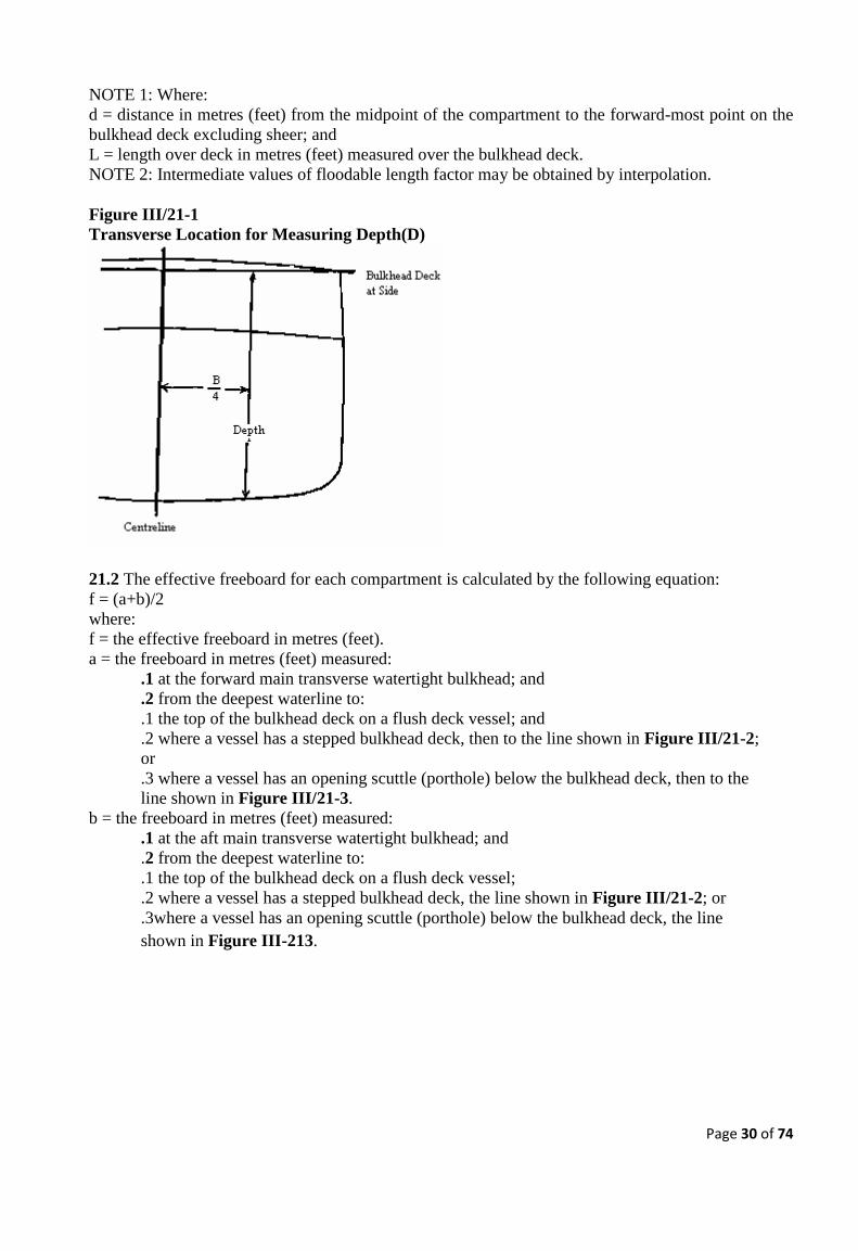
Page 30 of 74
NOTE 1: Where:
d = distance in metres (feet) from the midpoint of the compartment to the forward-most point on the
bulkhead deck excluding sheer; and
L = length over deck in metres (feet) measured over the bulkhead deck.
NOTE 2: Intermediate values of floodable length factor may be obtained by interpolation.
Figure III/21-1
Transverse Location for Measuring Depth(D)
21.2 The effective freeboard for each compartment is calculated by the following equation:
f = (a+b)/2
where:
f = the effective freeboard in metres (feet).
a = the freeboard in metres (feet) measured:
.1 at the forward main transverse watertight bulkhead; and
.2 from the deepest waterline to:
.1 the top of the bulkhead deck on a flush deck vessel; and
.2 where a vessel has a stepped bulkhead deck, then to the line shown in Figure III/21-2;
or
.3 where a vessel has an opening scuttle (porthole) below the bulkhead deck, then to the
line shown in Figure III/21-3.
b = the freeboard in metres (feet) measured:
.1 at the aft main transverse watertight bulkhead; and
.2 from the deepest waterline to:
.1 the top of the bulkhead deck on a flush deck vessel;
.2 where a vessel has a stepped bulkhead deck, the line shown in Figure III/21-2; or
.3where a vessel has an opening scuttle (porthole) below the bulkhead deck, the line
shown in Figure III-213.

Page 31 of 74
Figure III/21-2
Freeboard Measurement - Vessel with Stepped Bulkhead Deck
(a and b shown for two sample compartments)
Figure III/21-3
Freeboard Measurement - Vessel with Stepped Bulkhead Deck and
a Porthole Below the Bulkhead Deck
21.3 A vessel, required by sectionIII/20 to be fitted with watertight bulkheads shall be measured and
subdivided in accordance with the simplified subdivision calculation given in Annex 3
CHAPTER IV - MACHINERY
This section applies to all new ships unless otherwise stated and existing ships shall be complied
with as far as practicable.
PART A - GENERAL PROVISIONS
1 General requirements
1.1 The design, construction, installation and operation of propulsion and auxiliary machinery, piping
and pressure systems, steering apparatus and associated safety systems shall be to the satisfaction of
the Merchant Shipping Secretariat.
1.2 In all vessels, the main propulsion machinery and all auxiliary machinery essential to the
propulsion and the safety of the vessel shall be designed to operate when the vessel is upright and
when inclined at any angle of heel and trim up to and including 150
and 7.50
respectively either way
under static conditions.
1.3 Starting motors, generators, and any spark producing device shall be mounted as high above the
bilges as practicable. Electrical equipment in spaces, compartments, or enclosures that contain

Page 32 of 74
machinery powered by, or fuel tanks for, gasoline or other fuels having a flashpoint of 430
C (1100
F)
or lower shall be explosion-proof, intrinsically safe, or ignition protected for use in a gasoline
atmosphere.
1.4 Gauges to indicate engine revolutions per minute (RPM), jacket water discharge temperature, and
lubricating oil pressure shall be provided for all propulsion engines installed in the vessel. The
gauges shall be readily visible at the operating station.
1.5 A cover, guard or rail shall properly protect an exposed hazard, such as gears or rotating
machinery.
1.6.1 Shutoff valves, installed so as to close against the fuel flow, shall be fitted in the fuel supply
lines, one at the tank connection and one at the engine end of the fuel line to stop fuel flow when
servicing accessories. The shutoff valve at the tank shall be manually operable from outside the
compartment in which the valve is located, preferably from an accessible position on the weather
deck.
1.6.2 Where the handle to the shutoff valve at the tank is located inside the machinery space, it shall
be located so that the operator does not have to reach more than 300 mm (12 inches) into the
machinery space and the valve handle shall be shielded from flames by noncombustible material.
Electric solenoid valves shall not be used, unless used in addition to the manual valve.
1.7 Fuel filling and venting pipes shall be constructed of fuel compatible non-kinking material,
adequately supported and of sufficient dimensions to prevent spillage during filling. A venting pipe
shall be led to the open atmosphere, terminating in a position level with or higher than the fuel filling
mouth and its open end protected against:-
.1 water ingress - by a goose neck or other efficient means; and
.2 flame ingress - by a suitable gauze diaphragm, which can be detached for cleaning.
1.8 An air pipe, of greater than 10mm inside diameter, serving a fuel tank or other tank shall be
provided with a closing appliance of a type, which will prevent excessive pressure on the tank
boundaries. Provision shall be made for relieving a vacuum when tanks are being drawn from or
emptied.
1.9 Flexible non-metallic hose may be used in all systems subject to the following:
.1 when required by the machinery manufacturer, factory-assembled fittings shall be used;
.2 hose clamps may be used for other installations of short lengths not to exceed 760 mm (30
inches) and subject to pressures of not more than 35 kPa (5 psi);
.3 in a fuel supply system to engine unit the hose shall be fire resistant/metal reinforced or
otherwise protected from fire; and
.4 they shall be installed and located so as to minimize the risk of accidental damage.
1.10 In systems and applications where flexible hoses are permitted by sectionIV/1.9.2, to be
clamped:
.1 double hose clamping is required where practicable;
.2 the clamps shall be of a corrosion resistant metallic material;
.3 the clamps shall not depend on spring tension for their holding power; and
.4 two clamps shall be used on each end of the hose, or one hose clamp can be used where the
pipe ends are expanded or beaded to provide a positive stop against hose slippage.

Page 33 of 74
1.11 An enclosed space containing machinery powered by gasoline or other fuels, having a flash
point of 430
C (1100
F) or lower, shall be equipped with a flammable vapour detection device.
1.12 Piping used in the following systems shall be of ferrous material or other material where to the
satisfaction of the Merchant Shipping Secretariat.
.1 Fuel system;
.2 Fire main;
.3 CO 2
system fixed fire fighting;
.4 Bilge system;
.5 Steering system;
.6 Propulsion system and its necessary auxiliaries and controls;
.7 Vessel’s service and emergency electrical generation system and its necessary auxiliaries;
and
.8 A system identified by the Merchant Shipping Secretariat as being crucial to the survival of
the vessel or to the protection of the personnel on board.
1.13.1 Diesel tanks may only be integral with the hull where the ship is made of steel, aluminium or
GRP, sandwich construction is not acceptable. All other fuel tanks shall be independent of the hull.
1.13.2 Independent fuel tanks shall comply with the following:
.1 the tank shall be constructed of steel or aluminium;
.2 tubular glass shall be fitted only to a diesel tank and shall be of heat resistant material,
protected from mechanical damage, and provided with tank connection devices that
automatically close if the glass is ruptured;
.3 where any dimension of the tank exceeds 760mm (30) inches, the tank shall be fitted with
baffle plates to maintain strength and control the excessive surge of fuel;
.4 the interior of the tank shall be covered with a protective coating suitable for the type of
fuel carried.
1.13.3 Fuels tanks shall be pressure tested as appropriate
1.13.4 Fuel tanks shall be electrically bonded to a common ground.
1.13.5 Fuel tanks shall be adequately supported and braced to prevent movement.
2. Gasoline engines for propulsion
2.1 A vessel may be fitted with an inboard gasoline engine where:-
.1 the engine is located in an efficiently enclosed space to which a fixed fire extinguishing
system is fitted;
.2 provision is made to ventilate the engine space thoroughly before the engine is started;
.3 electrical devices within the engine and tank compartments have protection against ignition
of surrounding flammable gasses;
.4 any flexible hose used between the engine and any solidly mounted metallic line to
eliminate vibration failure is made of fire resistant fuel hose;
.5 not more than 12 passengers are carried; and
.6 the vessel is certified to operate only in protected waters and inshore waters.
2.2 A vessel fitted with one or more outboard gasoline engines:-
.1 shall be certified to operate in protected waters, inshore waters and exposed waters only;
.2 shall have the engines securely fastened to the hull;
Page 34 of 74
.3 where the engines are not permanently secured, the engines shall be provided with an
effective safety chain or cable;
.4 shall have effectively drained engine wells that are long enough for the engine to be tilted
up; and
.5 where the vessel is fitted with a single outboard engine, it shall, where it proceeds beyond
protected waters, have an auxiliary outboard engine of sufficient power to enable the vessel to
return safely to port or a safe haven.
2.3 Gasoline for outboard motors shall be stored:-
.1 in portable containers that can be readily jettisoned; or
.2 in a fixed-in-place inboard tank independent of the hull, where:-
.1 the vessel is a rigid hulled vessel or rigid/inflatable boat;
.2 in a safe place;
.3 the tank is tested to a design pressure of 0.3 bar,;
.4 the opening of the vent pipe from the petrol tank is protected by a flash proof fitting;
and
.5 where the possibility of accumulation of hydrocarbon vapours exists and where a
source of ignition may be present, a safe detector of hydrocarbon gas is fitted under or
adjacent to the tank.
.3 electrical devices within the engine and fuel tank compartments shall be protected against
ignition of any surrounding flammable gasses (explosion proof).
3 Ventilation of Spaces relating to Gasoline
3.1 A space containing machinery powered by, or fuel tanks for, gasoline shall have a ventilation
system that complies with this section and consist of the following:
.1 For an enclosed space:
.1 at least two natural ventilation supply ducts located at one end of the space and that
extend to the lowest part of the space or to the bilge on each side of the space; and
.2 a mechanical exhaust system consisting of at least two ventilation exhaust ducts located
at the end of the space opposite from where the supply ducts are fitted, which extend to
the lowest part or the bilge of the space on each side of the space, and which are led to
one or more powered exhaust blowers; and
.2 For a partially enclosed space, at least one ventilation duct installed in the forward part of
the space and one ventilation duct installed in the after part of the space, or as otherwise
required by the Merchant Shipping Secretariat. Ducts for partially enclosed spaces shall have
cowls or scoops as required by IV/3.9.
3.2 A mechanical exhaust system required by sectionIV/3.1.1(b) shall be such as to assure the air
changes as noted in Table IV.3.2 depending upon the size of the space.

Page 35 of 74
TABLE IV.3.2
Size of space in cubic metres (cubic feet)
Minutes per air change Over Not over
0
14 (500)
28.50 (1000)
43 (1500)
14(500)
28.5(1000)
43(1500)
………
2
3
4
5
3.3 An exhaust blower motor where mounted in any space required to be ventilated by this section,
shall be located as high above the bilge as practicable. Blower blades shall be non-sparking with
reference to their housings.
3.4 Where a fixed gas fire extinguishing system is installed in a space, all powered exhaust blowers
for the space shall shut down by emergency means upon release of the extinguishing agent.
3.5 Exhaust blower switches shall be located outside of any space required to be ventilated by this
section, and shall be of the type interlocked with the starting switch and the ignition switch so that
the blowers are started before the engine starter motor circuit or the engine ignition is energised. This
requirement is only applied to vessels with inboard engines with fuel tank in the same space.A red
warning sign at the switch shall state that the blowers shall be operated prior to starting the engines
for the time sufficient to insure at least one complete change of air in the space served.
3.6 The area of the ventilation ducts shall be sufficient to limit the air velocity to a maximum of 10
m/s(2,000 ft/min). A duct may be of any shape, provided that in no case will one cross sectional
dimension exceed twice the other.
3.7 A duct shall be so installed that ordinary collection of water in the bilge will not block air flow.
3.8 A duct shall be of rigid permanent construction, which does not allow any appreciable vapour
flow except through normal openings, and made of the same material as the hull or of non-
combustible material. The duct shall lead as directly as possible from its intake opening to its
terminus and be securely fastened and supported.
3.9 A supply duct shall be provided at its intake opening with a cowl or scoop having a free area not
less than twice the required duct area. When the cowl or scoop is screened, the mouth area shall be
increased to compensate for the area of the screen wire. A cowl or scoop shall be kept open at all
times, except when the weather is such as to endanger the vessel if the openings are not temporarily
closed.
3.10 A duct opening may not be located where the natural flow of air is unduly obstructed, adjacent
to possible sources of vapour ignition, or where exhaust air may be taken into a supply duct.
3.11 Provision shall be made for closing all supply duct cowls or scoops and exhaust duct discharge
openings for a space protected by a fixed gas extinguishing system. All closure devices shall be
readily available and mounted in the vicinity of the vent.

Page 36 of 74
4. Ventilation of spaces relating to diesel.
4.1 A space containing diesel machinery shall be fitted with at least two ducts to furnish natural or
powered supply and exhaust ventilation. The total inlet area and the total outlet area of each
ventilation duct shall not be less than 650 mm2
(one square inch) for each 300 cm of beam of part of
the air supply to the engines.
4.2 A duct shall be of rigid permanent construction, which does not allow any appreciable vapor flow
except through normal openings, and made of noncombustible material. The duct shall lead as
directly as possible from its intake opening to its terminus and be securely fastened and supported.
4.3 A supply duct shall be provided with a cowl or scoop having a free area not less than twice the
required duct area, which shall be kept open at all times except when the weather is such as to
endanger the vessel if the openings are not temporarily closed.
4.4 Dampers shall not be fitted in a supply duct.
4.5 A duct opening shall not be located where the natural flow of air is unduly obstructed, adjacent to
possible sources of vapor ignition, or where exhaust air may be taken into a supply duct.
4.6 Provision shall be made for closing all supply duct cowls or scoops and exhaust duct discharge
openings for a space protected by a fixed gas extinguishing system. All closure devices shall be
readily available and mounted in the vicinity of the vent.
4.7 A space containing a diesel fuel tank and no machinery shall meet the following requirements: -
.1 A space of 14 m3
(500 ft3
) or more in volume shall have a gooseneck vent of not less than
65 mm (2.5 inches) in diameter.
.2 A space of less than 14 m3
(500 ft3
) in volume shall have a gooseneck vent of not less than
40 mm (1.5 inches) in diameter.
.3 Vent openings shall not be located adjacent to possible sources of vapor ignition.
5 Exhausts
An engine exhaust outlet, which penetrates the hull below the weather deck, shall be provided with
means to prevent backflooding into the hull through the exhaust system. The means may be provided
by system design or arrangement, built-in valve or a portable fitting, which can be applied readily in
an emergency.
6 Engine Starting
6.1 An engine shall be provided with either:
.1 hand starting;
.2 mechanical;
.3 electric starting with independent batteries installed in accordance with sectionIV/21; or
.4 other means of starting acceptable to the Merchant Shipping Secretariat.

Page 37 of 74
6.2 When the sole means of starting is by battery, the battery shall be installed in accordance with
sectionIV/21 and be in duplicate and connected to the starter motor by means of a “change over
switch” so that either battery or both can be used for starting the engine. In normal circumstances, the
use of both batteries in parallel should be avoided to prevent simultaneous discharge of both
batteries. Charging facilities shall be available for the batteries when the engine is running.
7 Portable Plant
7.1 Any portable plant provided on board powered by a petrol engine shall be fitted on the weather
deck and properly secured to prevent movement.
7.2 A deck locker or protective enclosure for the portable plant shall have no openings to an enclosed
space within the hull of the vessel and the locker or protective enclosure shall be adequately
ventilated and drained.
7.3 Petrol tanks provided for the engine shall comply with the following:
.1 fuel is supplied to the engine from a portable tank of 27 litres or less in capacity complying
with the requirements of ISO 13591 - Portable fuel systems for outboard motors – or its
equivalent National Standard; and
.2 a small marinised petrol engine, of less than 3.75 kW (5 horse power), manufactured with
an integral fuel tank is acceptable for either outboard propulsion or portable plant provided a
safety warning sign is displayed with details of appropriate precautions to be taken when
filling the fuel tank.
8 Propulsion Engine Control Systems
8.1 A vessel shall have a reliable means for shutting down a propulsion engine, at the main operating
station, which is independent of the engine’s speed control.
8.2 A propulsion engine control system, including control at the operating station, shall be designed
so that a loss of power to the control system does not result in an increase in shaft speed or propeller
pitch.
PART B - STEERING AND PROPELLER SYSTEMS
9 Main Steering Gear
9.1 A vessel shall be provided with main steering gear that is:
.1 of adequate strength and capable of steering the vessel at all service speeds;
.2 designed to operate at maximum astern speed without being damaged or jammed; and
.3 capable of moving the rudder from 350
on one side to 300
on the other side in not more than
28 seconds with the vessel moving ahead at maximum service speed.
9.2 For vessels of more than 20m(65ft) in length the control of the main steering gear, including
control of any necessary associated devices, motor, pump, valve, etc., shall be provided from the
operating station.

Page 38 of 74
9.3 The main steering gear shall be designed so that transfer of control from the main steering gear to
the auxiliary means of steering required by sectionIV/10 can be achieved rapidly. Any tools or
equipment necessary to make the transfer shall be readily available.
9.4 The vessel’s operating station shall be arranged to permit the person steering to have the best
possible all around vision.
9.5 Strong and effective rudder stops shall be provided to prevent jamming and damage to the rudder
and its fittings. These stops may be structural or internal to the main steering gear.
9.6 In addition to meeting the requirements of IV/9.1 to 9.5, a vessel of more than 20m (65 ft) in
length with a power driven main steering gear shall be provided with the following:
.1 a disconnect switch located in the steering compartment, and instantaneous short circuit
protection for electrical power and control circuits ;
.2 an independent rudder angle indicator at the operating station;
.4 a manual means to centre and steady the rudder(s) in an emergency; and
.5 a limit switch to stop the steering gear before it reaches the rudder stops required by
IV/9.5. 9.7 A vessel of more than 20 m (65 feet) in length with a power driven main steering gear shall in
addition be provided with the following:
.1 a visual means, located at the operating station, to indicate operation of the power units;
and
.2 instructions for transfer procedures from the main steering gear or control to the auxiliary
means of steering required by section IV/ 10, posted at the location where the transfer is
carried out.
10 Auxiliary Means of Steering
10.1 Except as provided in IV/10.3, a vessel shall be provided with an auxiliary means of steering
that is:
.1 of adequate strength;
.2 capable of moving the rudder from 150
on one side to 150
on the other side in not more than
60 seconds with the vessel at one-half its maximum service speed ahead, or 7 knots,
whichever is greater; and
.3 controlled from a location that permits safe manoeuvring of the vessel and does not expose
the person operating the auxiliary means of steering to personnel hazards during normal or
heavy weather operation.
10.2 A suitable hand tiller may be used as the auxiliary means of steering.
10.3 An auxiliary means of steering need not be provided where:
.1 the main steering gear and its controls are provided in duplicate;
.2 multiple propeller propulsion, with independent control from the operating position for
each screw, is provided, and the vessel is capable of being steered from the control station;
.3 no regular rudder is fitted and steering action is obtained by a change of setting of the
propelling unit; or
.4 where a rudder and hand tiller are the main steering gear.
Page 39 of 74
11 Propeller Systems
Construction and fitting standards for propellers and associated fittings shall be to the satisfaction of
the Merchant Shipping Secretariat. Recognised design standards shall be used.
PART C - BILGE SYSTEMS
12 General Provisions for Bilge Systems
A vessel shall be provided with a satisfactory arrangement for draining any watertight compartment,
other than small buoyancy compartments, under all practicable conditions. Sluice valves shall not be
fitted in watertight bulkheads.
13 Bilge piping system
13.1 A vessel of 8 m (26 feet) or more in length shall be provided with individual bilge lines and
bilge suctions for each watertight compartment, except that the space forward of the collision
bulkhead need not be fitted with a bilge suction line when the arrangement of the vessel is such that
ordinary leakage may be removed from this compartment by the use of a hand portable bilge pump or
other equipment, and such equipment is provided.
13.2 A bilge pipe in a vessel of less than 20 m (65 feet) in length shall be not less than 25 mm (1
inch) nominal pipe size. A bilge pipe in a vessel of 20 m or more (65 feet) in length shall be not less
than 40 mm (1.5 inches) nominal pipe size. Bilge suction shall be fitted with a suitable strainer
having an open area not less than three times the area of the bilge pipe.
13.3 Except when individual pumps are provided for separate spaces, individual bilge suction lines
shall be led to a central control point or manifold and provided with a stop valve at the control point
or manifold and a non-return valve at some accessible point in the bilge line. A stop non-return valve
located at a control point or manifold will meet the requirements for both a stop valve and a non-
return valve.
13.4 A bilge pipe piercing the collision bulkhead shall be fitted with a screw-down valve located on
the forward side of the collision bulkhead and operates from the weather deck, or, where it is readily
accessible under service conditions, a screw-down valve without remote operation may be fitted to
the bilge line on the after side of the collision bulkhead.
14 Bilge pumps
14.1 A vessel shall be provided with bilge pumps in accordance with Table IV.14.1. A second power
pump is an acceptable alternative to a hand pump where it is supplied by a source of power
independent of the fixed power bilge pump. Individual power pumps used for separate spaces are to
be controlled from a central control point and shall have a light or other visual means at the control
point to indicate operation.

Page 40 of 74
TABLE IV/14.1
14.2 A portable hand bilge pump shall be:
.1 capable of pumping water, but not necessarily simultaneously, from all watertight
compartments; and
.2 provided with suitable suction and discharge hoses capable of reaching the bilges for each
watertight compartment.
14.3 Each fixed power bilge pump shall be self-priming. It may be driven off the main engine or
other source of power. It shall be permanently connected to the bilge manifold and may also be
connected to the fire main. A power bilge pump may also serve as a fire pump provided it meets the
requirements of sectionV/7.
14.4 Where two fixed power bilge pumps are installed, they shall be driven by different sources of
power. Where one pump is driven off the main engine in a single propulsion engine installation, the
other shall be independently driven. In a twin propulsion engine installation, each pump may be
driven off a different propulsion engine.
14.5 A submersible electric bilge pump may be used as a power bilge pump required by Table
IV.14.1 only on a vessel of less than 20 m (65 feet) in length carrying less than 50 passengers, other
than a ferry, provided that:
.
.1 the pump is used to pump out not more than one watertight compartment;
.2 the pump is permanently mounted;
.3 the pump is equipped with a strainer that can be readily inspected and cleaned without
removal of the pump;
.4 the pump discharge line is suitably supported;
.5 the opening in the hull for the pump discharge shall be placed so that it is above the
waterline when the vessel is heeled and trimmed to 15 degrees and 7½ degrees respectively;
.6 a positive non return valve is installed at the hull penetration; and
.7 the capacity of the electrical system, including wiring, and size and number of batteries, is
designed to allow all bilge pumps to be operated simultaneously.
Page 41 of 74
14.6 A flexible tube or hose may be used instead of fixed pipe for the discharge line of a submersible
electric bilge pump provided the hose or tube does not penetrate any required watertight bulkheads. It
shall be of good quality and of substantial construction, suitable for the intended use; and highly
resistant to salt water, petroleum oil, heat, and vibration, and shall be located so as to minimize the
risk of accidental damage.
14.7 Where a fixed hand pump is used to comply with Table IV.14.1, it shall be permanently
connected to the bilge system.
14.8 On a vessel of less than 20 m (65 feet) in length, a power driven fire pump required by
sectionV/7 may serve as a fixed power bilge pump required by sectionIV/14.1, provided it has the
minimum flow rate required by Table IV.14.1.
14.9 On a vessel of 20 m or more (65 feet) in length, a power driven fire pump required by
sectionV/7 may serve as one of the two fixed power bilge pumps required by sectionIV/14.1,
provided it has the minimum flow rate required by Table IV.14.1.
14.10 Where the bilge and fire pump systems are interconnected, the dedicated bilge pump is to be
capable of pumping the bilges overboard at the same time as the fire/bilge pump charges the
firemain. Stop valves and check valves shall be installed in the piping to isolate the systems during
simultaneous operation and prevent possible flooding through the bilge system.
14.11 A catamaran vessel shall be equipped with bilge pumps for each hull, as if each hull is a
separate vessel, in accordance with Table IV.14.1, except where:
.1 one dedicated pump is located in each hull;
.2 each dedicated pump is driven by an independent source of power; and
.3 the bilge pumping system is permanently cross-connected between hulls to facilitate
pumping of either hull by either bilge pump.
.4 isolating valves shall be fitted within the cross connection to prevent flooding from one
hull to another.
15 Bilge high level alarms
15.1 On a vessel 8 m (26 feet) or more in length, a visual and audible alarm shall be provided at the
operating station to indicate a high water level in each of the following spaces:
.1 a space with a through-hull fitting below the deepest load waterline, such as a lazarette;
.2 a machinery space bilge, bilge well, shaft alley bilge, or other spaces subject to flooding
from sea water piping within the space; and
.3 a space with a non-weathertight closure, such as a space with a non-weathertight hatch on
the main deck.
15.2 Vessels constructed of wood shall, in addition to IV/15.1, provide bilge level alarms in all
watertight compartments except buoyancy chambers of less than 0.25 m3
.
15.3 A visual indicator shall be provided at the operating station to indicate when any automatic bilge
pump is operating

Page 42 of 74
PART D - ELECTRICAL ARRANGEMENTS
16 General Provisions
16.1 The requirements for the design, construction, installation and operation of electrical equipment
and systems including power sources, lighting, motors, miscellaneous equipment and safety systems
shall be in accordance with accepted standards or to the satisfaction of the Merchant Shipping
Secretariat.
16.2 Electrical equipment on a vessel shall be installed and maintained to:
.1 provide services necessary for safety under normal and emergency conditions;
.2 protect passengers, crew, other persons, and the vessel from electrical hazards, including
fire, caused by or originating in electrical equipment, and electrical shock;
.3 minimize accidental personnel contact with energized parts; and
.4 prevent electrical ignition of flammable vapors.
16.3 Electrical equipment used in the following locations shall be drip-proof:
.1 a machinery space;
.2 a location normally exposed to splashing, water washdown, or other wet conditions within
a galley, a laundry, or a public washroom or toilet room that has a bath or shower; or
.3 another space with a similar moisture level.
16.4 Electrical equipment exposed to the weather shall be weathertight.
16.5 Electrical equipment exposed to corrosive environments shall be demonstrated to be of suitable
construction and corrosion- resistant.
16.6 Electrical equipment and installation shall be designed and installed so that it is not affected by
vessel motions or vibration of the vessel underway.
16.7 All equipment, including switches, fuses, lampholders, etc., shall be rated for the voltage and
current utilized.
16.8 Receptacle outlets of the type providing a grounded pole or a specific direct current polarity
shall be of a configuration that will not permit improper connection.
16.9 All electrical equipment and circuits may be clearly marked and identified.
16.10 Any cabinet, panel, box or other enclosure containing more than one source of power shall be
fitted with a sign warning persons of this condition and identifying the individual circuits.
17 Power Sources
17.1 Vessels of more than 20m that relies on electricity to power the following loads shall be
arranged so that the loads can be energized from two sources of electricity:
.
.9 emergency lighting except for decorative lights;
10 communication systems including a public address system required under sectionVII/6;
.11 navigation equipment and lights; and
.12 illumination of the survival craft launching and embarkation areas and man overboard
rescue equipment and rescue areas.
Page 43 of 74
17.2 A vessel with batteries of adequate capacity to supply the loads specified in IV/17.1 for three
hours, or a generator or alternator driven by a propulsion engine, complies with the requirement of
IV/17.1.
17.3 Where a vessel service generator driven by a propulsion engine is used as a source of electrical
power, a vessel speed change, throttle movement or change in direction of the propeller shaft rotation
shall not interrupt power to any of the loads specified in IV/17.1.
17.4 Each generator and motor shall be:
.1 in a location that is accessible, adequately ventilated, and as dry as practicable; and
.2 mounted above the bilges to avoid damage by splash and to avoid contact with low lying
vapors.
17.5 A voltmeter and an ammeter shall be provided for a generator rated at 50 volts or more. For
each alternating current generator, a means for measuring frequency shall also be provided.
17.6 Each generator shall be protected by an overcurrent device with set value not exceeding 115 per
cent of the generator full load rating.
17.7 A dual voltage generator installed on a vessel shall be of the grounded type, where:
.1 the neutral of a dual voltage system shall be solidly connected at the switchboard’s neutral
bus; and
.2 the neutral bus shall be connected to ground.
18 Electrical Systems
18.1 Electrical systems shall be two wire.
18.2 A system in which there is no intentional connection of the circuit to earth (an insulated system)
shall be provided with double pole switches, except that single pole switches may be used in the final
sub-circuit.
18.3 Single pole switches are accepted in a system with one pole earthed. Fuses shall not be installed
in an earthed conductor.
18.4 The insulation resistance, using a low voltage instrument so as not to cause damage, shall not be
less than 0.3 mega ohm for all new vessels, but a minimum of 0.1 mega ohm can be accepted on
existing vessels.
18.5 All circuits, except the main supply from the battery to the starter motor and electrically driven
steering motors, shall be provided with electrical protection against overload and short circuit, i.e.
fuses or circuit breakers shall be installed. Short circuit protection shall be for more than twice the
total rated current of the loads in the circuit protected.
18.6 Steering motors shall have an overload alarm in lieu of overload protection.
19 Cables and Wiring
19.1 Electrical cables shall be constructed and fitted to a recognised standard for marine use.

Page 44 of 74
19.2 Cables which are not provided with electrical protection shall be kept as short as possible and
shall be “short circuit proofed” e.g. single core with additional insulated sleeve over the insulation of
each core. Single core marine cable, which has conductor insulation and a sheath, will meet this
requirement without an additional sleeve.
19.3 All wiring shall be carried out with flame retardant cable. When selecting cables for relevant
applications, particular attention shall be given to environmental factors such as temperature and
contact with damaging substances e.g. oils and chemicals.
19.4 Adequate provision shall be made for securing electrical connections, e.g. by use of locking
washers.
19.5 Electrical cables shall be installed with due regard to minimizing physical damage and the effect
of moisture.
20 Batteries
20.1 Where provisions are made for charging batteries, there shall be natural or induced ventilation
sufficient to dissipate the gases generated.
20.2 Each battery shall be located as high above the bilge as practicable, secured to protect against
shifting with the roll and pitch of the vessel, and free from exposure to water splash or spray.
20.3 Connections shall be made to battery terminals with permanent type connectors. Spring clips or
other temporary clamps are prohibited.
20.4 A battery cut-out switch which acts as an isolator shall be provided for all systems. Where a
battery change-over switch is fitted and is provided with an “off” position, this may serve as the cut-
out switch also.
20.5 Batteries shall be mounted in trays lined with, or constructed of, a material that is resistant to
damage by the electrolyte.
20.6 Battery chargers shall have an ammeter connected in the charging circuit.
20.7 Batteries used for engine starting shall be located as close as possible to the engine or engines
served.
21 Battery Installation
21.1 Each battery installation connected to a battery charger having an output of more than 2 kW,
shall be located in a locker, room or enclosed box solely dedicated to the storage of batteries with
adequate ventilation.
21.2 Each battery installation connected to a battery charger having an output of 2 kW or less, shall
be located in a well-ventilated space and protected from falling objects and shall not be in a closet,
storeroom or similar space.
22 General grounding requirements
22.1 A vessel’s hull shall not carry current as a conductor except for the following systems:
.1 impressed current cathodic protection systems; or
.2 battery systems for engine starting.

Page 45 of 74
22.2 Receptacle outlets and attachment plugs for portable lamps, tools, and similar apparatus
operating at 100 volts or more, shall have a grounding pole and a grounding conductor in the portable
cord.
22.3 Each nonmetallic mast and top mast shall have a lighting ground conductor.
23 Lighting
23.1 A single hazardous event shall not be capable of disabling all lighting systems.
23.2 Lighting circuits shall be distributed through the spaces so that a total blackout cannot occur due
to the failure of a single protective device.
23.3 Where general lighting is provided by a single centralised source, an alternative source of
lighting shall also be provided sufficient to enable persons to make their way to the open deck or to
permit work on essential machinery.
24 Hazardous Spaces
24.1 Where practicable, electrical equipment shall not be installed in a space where petroleum vapour
or other hydrocarbon gas may accumulate. When equipment is installed in such a space it shall
comply with a recognised standard for prevention of ignition of flammable atmosphere.
24.2 Any compartment which contains a gas consuming appliance or any compartment into which
flammable gas may leak or accumulate, shall be provided with a hydrocarbon gas detector and alarm.
The detector and alarm shall be designed to comply with a recognised standard for prevention of
ignition of flammable atmosphere.
CHAPTER V - FIRE PROTECTION
This section applies to all new ships unless otherwise stated and existing ships shall be complied
with as far as practicable.
PART A - GENERAL PROVISIONS
1 Fire Protection Provisions
1.1 Machinery and fuel tank spaces shall be separated from accommodation spaces by boundaries,
which prevent the passage of vapours.
1.2 Paint and flammable liquid lockers shall be constructed of steel or equivalent material.
1.3 Vapour barriers shall be provided in spaces where flammable and combustible liquids or vapours
are present.

Page 46 of 74
1.4 Survival craft shall be protected from fire hazards. Where a survival craft is stowed directly
above an area of fire hazard, the structure separating the survival craft and the area of fire hazard
shall be constructed to comply with A-15 structural fire protection standard.
2 Machinery Space - Construction
2.1 Steel Construction: Vessels which have the machinery space boundaries constructed of steel,
require no additional fire protection. However, the surfaces of machinery space bulkheads that are
outside of the machinery space shall be coated only with finishes which meet the requirements for
low flame spread when tested in accordance with Resolution A.653 (16) of the International
Maritime Organization.
2.2 Fibre Reinforced Plastic (FRP) Construction: Machinery space boundaries should prevent the
passage of smoke and flame for 15 minutes, when tested in accordance with the procedure shown in
Annex 4. Fire resistance of FRP may be achieved by the use of woven roving glass layers or
additives to the resin, or by insulation. Intumescent polyester resin surface coatings may also be used;
however, solvent-borne intumescent paints shall not be used. The Merchant Shipping Secretariat may
waive the requirement for the test described in Annex 4 where the construction complies with an ISO
or equivalent standard to give at least the same level of protection.
2.3 Aluminium and Wood Construction: Machinery space boundaries shall have an equivalent level
of fire protection when compared with GRP construction as required in sectionV/2.2.
2.4 Machinery space boundaries shall be as gastight as practicable so that in the event of a fire the
fire extinguishing medium released or injected can be retained for sufficient time to extinguish the
fire.
2.5 Where it is not practical to have a machinery space, the engine shall be enclosed in a box. The
box shall perform the same function as the machinery space boundaries in sectionV/2.4.
2.6 Portlights or windows shall not be fitted in the boundary of the machinery space, except that an
observation port having a maximum diameter of 150mm may be fitted, provided the frame is
constructed of steel or brass and the port is fitted with a permanently attached steel or brass cover
with securing arrangements
3 Insulation
3.1 Insulating materials fitted in the machinery space of new vessels shall be non-combustible when
tested in accordance with Resolution A.799(19) of the International Maritime Organization.
Insulating materials fitted in the engine space of existing vessels shall not be readily ignitable.
Insulation shall be covered with a material impervious to oil or oil vapour.
3.2 Any insulation composite may be considered not readily ignitable where the test defined in
Annex 5 is carried out on a representative specimen and the result is satisfactory. In such testing, the
specimen edge need not be tested where the insulation is fitted without exposed edges and specimen
conditioning may be curtailed as appropriate to the material under test.
3.3 On existing vessels where insulation is readily ignitable, it shall be replaced as soon as possible,
if practicable but not later than three years of the coming into force of the Code.
Page 47 of 74
4 Cooking Appliances
4.1 Fire protection arrangements in cooking spaces shall be in accordance with the following:
.1 in the case of a small cooking area that is common with the accommodation, the structural
fire protection fitted shall be dependent on the fire hazard presented by the cooking
appliances in the area;
.2 cooking appliances such as deep-fat fryers or other appliances presenting a high fire hazard
are not permitted unless the compartment in which they are situated is fitted with a fixed fire
extinguishing system;
.3 suitable fire retardant barriers shall be built around the cooking and heating appliances
where they are adjacent to combustible materials and structures;
.4 cooking range exhaust hoods and ducts shall be fitted with a grease trap;
.5 combustible materials not needed in the cooking area shall be stored away from the area;
Materials which are in the vicinity of an open flame cooking appliance shall be non-
combustible, except that these materials may be faced with any surface finish which meet the
requirements for low flame spread when tested in accordance with Resolution† A.653(16) of
the International Maritime Organization.
4.2 Combustible materials and other surfaces which do not meet the requirements for low flame
spread shall not be left unprotected within the following distances of the cooker:-
.1 600mm vertically above the cooker, for horizontal surfaces,
.2 600mm horizontally from the cooker, for vertical surfaces.
4.3 Curtains shall not be fitted within 900mm of an open flame cooking appliance.
5 Fire Safety
5.1 When spare petrol is carried on board in portable containers for any purpose, the containers shall
be clearly marked and shall be stowed on the weather deck where they can be readily jettisoned and
where spillage will drain directly overboard. Except as to the satisfaction of the Merchant Shipping
Secretariat a portable container shall not exceed 27 litres (6 gallons) and the quantity of petrol and
number of containers shall be kept to a minimum.
5.2 Combustible materials not required for the operation and maintenance of machinery shall not be
stowed in the machinery space. Any materials stowed in the machinery space shall be properly
secured and cause no obstruction to access in or from the space.
5.3 Gas welding and cutting equipment, where carried, shall be stowed in secure manner on the open
deck at a safe distance away from any potential source of fire and shall have the capability of being
readily jettisoned overboard where necessary.
5.4 Machinery containing oil shall be provided with a readily accessible galvanised steel drip tray or
other suitable means to collect and retain leakages containing oil. The machinery space shall be kept
clean and tidy. Oily water shall be collected and properly disposed of ashore.
5.5 Fire hazards shall be minimised in so far as it is reasonable and practicable and combustible
materials shall be insulated from heated surfaces such as exhaust pipes and manifolds.
5.6 Savealls or equivalent means of containment of spillage shall be provided below fuel pumps and
filters.
Page 48 of 74
PART B - FIRE EXTINGUISHING AND DETECTING EQUIPMENT
6 Equipment installed but not required
Fire extinguishing and detecting equipment installed on a vessel in excess of the requirements shall
be designed, constructed, installed and maintained in accordance with a recognised industry standard
acceptable to the Merchant Shipping Secretariat.
7 Fire pumps
7.1 A self-priming, power driven fire pump or a hand pump shall be installed on each vessel of 15 m
(50feet) or more in length. The power driven pump shall be capable of projecting a jet of water at
least 7.5 m (25 feet) from the nozzle of a hose attached to any hydrant in the system with one hydrant
open. The hand pump shall be capable of delivering one jet of water to any part of the ship through a
hose and nozzle.
7.2 A fire pump may be driven by a propulsion engine where the propeller shaft can be readily
disengaged or a controllable pitch propeller is fitted. A fire pump shall be permanently connected to
the fire main where fitted and may be connected to the bilge system.
7.3 Where the fire pump is located in the machinery space, it shall be capable of both remote
operation from the operating station and local, manual operation at the pump.
8 Fire main and hydrants
A vessel that has a power driven fire pump shall have a sufficient number of fire hydrants to reach
any part of the vessel using a single length of fire hose.
9 Fire hoses and nozzles
9.1 A fire Hose shall be stored near each fire hydrant.
9.2 On a vessel of less than 20 m (65 feet) in length, carrying 50 or more passengers, and on a vessel
of 20 m (65 feet) in length or over, each hose shall be to recognized standards and be not less than
7.5 m (25 feet) or more than 15 m (50 feet) in length and 40 mm (1.5 inches) in diameter. It shall
have fittings of brass or other suitable material.
9.3 Each fire hose on a vessel of less than 20 m in length carrying less than 50 passengers shall be to
be of one piece not less than 7.5 m (25 feet) and not more than 15 m (50 feet) in length. It shall have
fittings of brass or other suitable material
9.4 Each nozzle shall be of corrosion-resistant material and be capable of being changed between a
solid stream and a spray pattern. A nozzle on a vessel of less than 20 m (65 feet) in length carrying
50 or more passengers, and on a vessel of 20 m or more in length, shall be of a type to the
satisfaction of the Merchant Shipping Secretariat.
10 Requirement for Fixed Fire Extinguishing and Detecting Systems
10.1 Subject to V/10.2, the following spaces shall be equipped with a fixed gas or other fixed fire
extinguishing system to the satisfaction of the Merchant Shipping Secretariat.
.1 a space containing an internal combustion engine of more than 375 kW ;
Page 49 of 74
.2 a space containing an oil fired boiler;
.3 a space containing machinery powered by gasoline or other fuels having a flash point of 43 0
C (110 0
F) or lower;
.4 a space containing a fuel tank for gasoline or any other fuel having a flash point of 43 0
C
(110 0
F) or lower;
.5 a space containing a combustible cargo or vessel’s stores inaccessible during the voyage;
.6 a paint locker; and
.7 a storeroom containing flammable liquids, including liquors of 80 proof or higher where
liquor is packaged in individual containers of 9.5 liters (2.5 gallons) capacity or greater.
10.2 A fixed fire extinguishing system in accordance with sectionV/10.1 is not required in a space
where:-
.1 the space is open to the atmosphere and the Merchant Shipping Secretariat determines that
a fixed gas fire extinguishing system would be ineffective; or
.2 the amount of carbon dioxide gas required in a fixed fire extinguishing system can be
supplied by one portable extinguisher or a semi-portable extinguisher meeting the following
requirements:
.1 cylinders shall be installed in a fixed position outside the space protected;
.2 the applicator shall be installed in a fixed position so as to discharge into the space
protected;
.3controls shall be installed in an accessible location outside the space protected.
10.3 Except where the space is manned, the following spaces shall be equipped with a fire detecting
system of an approved type that is installed to the satisfaction of the Merchant Shipping Secretariat:
.
.1 a space containing an internal combustion engine of more than 375 kW;
.2 a space containing oil fired boiler;
.3 a space containing machinery powered by gasoline or any other fuels having a flash point
of 43 0
C (110 0
F) or lower;
.4 a space containing a fuel tank for gasoline or any other fuel having a flash point of 43 0
C
(110 0
F) or lower; and
.5 each overnight accommodation space on a vessel with overnight accommodation for
passengers.
10.4 When a fixed fire extinguishing system, which is not a portable extinguisher, is installed in a
machinery space, it shall be of a type to the satisfaction of the Merchant Shipping Secretariat
Such fixed installation systems in machinery spaces include:-
.1 low expansion foam;
.2 medium expansion foam;
.3 high expansion foam;
.4 carbon dioxide;
.5 pressure water spraying; and
.6 vaporising fluids.
10.5 All grills, broilers, and deep fat fryers shall be fitted with a grease extraction hood to the
satisfaction of the Merchant Shipping Secretariat.
10.6 A fixed gas fire extinguishing system may protect more than one space. The quantity of
extinguishing agent shall be at least sufficient for the space requiring the greatest quantity.
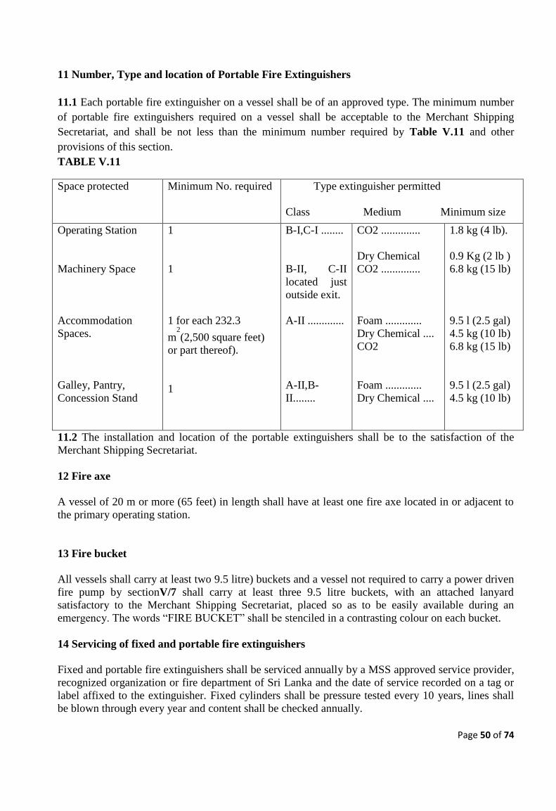
Page 50 of 74
11 Number, Type and location of Portable Fire Extinguishers
11.1 Each portable fire extinguisher on a vessel shall be of an approved type. The minimum number
of portable fire extinguishers required on a vessel shall be acceptable to the Merchant Shipping
Secretariat, and shall be not less than the minimum number required by Table V.11 and other
provisions of this section.
TABLE V.11
Space protected Minimum No. required Type extinguisher permitted
Class Medium Minimum size
Operating Station
Machinery Space
Accommodation
Spaces.
Galley, Pantry,
Concession Stand
1
1
1 for each 232.3
m2
(2,500 square feet)
or part thereof).
1
B-I,C-I ........
B-II, C-II
located just
outside exit.
A-II .............
A-II,B-
II........
CO2 ..............
Dry Chemical
CO2 ..............
Foam .............
Dry Chemical ....
CO2
Foam .............
Dry Chemical ....
1.8 kg (4 lb).
0.9 Kg (2 lb )
6.8 kg (15 lb)
9.5 l (2.5 gal)
4.5 kg (10 lb)
6.8 kg (15 lb)
9.5 l (2.5 gal)
4.5 kg (10 lb)
11.2 The installation and location of the portable extinguishers shall be to the satisfaction of the
Merchant Shipping Secretariat.
12 Fire axe
A vessel of 20 m or more (65 feet) in length shall have at least one fire axe located in or adjacent to
the primary operating station.
13 Fire bucket
All vessels shall carry at least two 9.5 litre) buckets and a vessel not required to carry a power driven
fire pump by sectionV/7 shall carry at least three 9.5 litre buckets, with an attached lanyard
satisfactory to the Merchant Shipping Secretariat, placed so as to be easily available during an
emergency. The words “FIRE BUCKET” shall be stenciled in a contrasting colour on each bucket.
14 Servicing of fixed and portable fire extinguishers
Fixed and portable fire extinguishers shall be serviced annually by a MSS approved service provider,
recognized organization or fire department of Sri Lanka and the date of service recorded on a tag or
label affixed to the extinguisher. Fixed cylinders shall be pressure tested every 10 years, lines shall
be blown through every year and content shall be checked annually.
Page 51 of 74
15 Fire Blanket
All ships which have a galley or cooking area shall be provided with a fire blanket which is
positioned such that is available for immediate use in the event of a fire in the galley or cooking area.
CHAPTER VI - LIFESAVING EQUIPMENT
1 General Provisions
1.1 All survival craft shall be of approved type in accordance with the section I/5 of this code.
1.2 Lifesaving appliances on existing vessels shall be in compliance with recognized standards.
2 Number and Type of Survival Craft
2.1 Vessels certified to operate in exposed waters and unrestricted waters shall carry lifeboats or life
rafts sufficient to accommodate the total number of persons on board.
2.2 Vessels making voyages in inshore waters shall carry lifeboats or life rafts, or buoyant apparatus,
and passenger vessels operating solely in protected waters shall carry life rafts or buoyant apparatus,
approved in accordance with section I/4, sufficient to accommodate the total number of persons on
board.
2.3 Where the life-saving appliances and their launching appliances, where applicable, are not
accessible from both sides of the vessel, additional life-saving appliances shall be fitted.
2.4 The means and arrangements for embarkation into the survival craft shall be adequate, clearly
marked and illuminated and to the satisfaction of the Merchant Shipping Secretariat.
2.5 The manufacturer’s model identification and number of survivors for which the apparatus was
approved shall be recorded on a tag or label and affixed to the apparatus.
2.6 All survival craft shall be of approved type in accordance with the section I/5 of this code.
3 EPIRB, SART and Radar Reflector
3.1 Each vessel certified to operate in unrestricted waters and passenger vessels certified to operate in
exposed water operation -2 shall carry:
.1 a 406 MHz Emergency Position Indicating Radio Beacon (EPIRB), installed to
automatically float free and activate, and
.2 a 121.5 MHz Search and Rescue Radar Transponder (SART) so stowed that can be easily
utilized. The SART need not be carried if the 406 MHz EPIRB required under VI/3.1.1 has a
121.5 MHz transmitting capability.
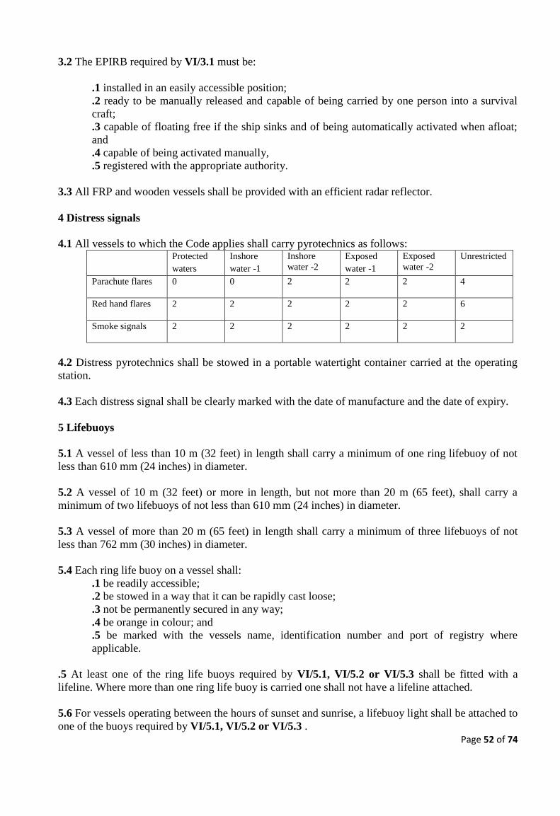
Page 52 of 74
3.2 The EPIRB required by VI/3.1 must be:
.1 installed in an easily accessible position;
.2 ready to be manually released and capable of being carried by one person into a survival
craft;
.3 capable of floating free if the ship sinks and of being automatically activated when afloat;
and
.4 capable of being activated manually,
.5 registered with the appropriate authority.
3.3 All FRP and wooden vessels shall be provided with an efficient radar reflector.
4 Distress signals
4.1 All vessels to which the Code applies shall carry pyrotechnics as follows:
Protected
waters
Inshore
water -1
Inshore
water -2
Exposed
water -1
Exposed
water -2
Unrestricted
Parachute flares 0 0 2 2 2 4
Red hand flares 2 2 2 2 2 6
Smoke signals 2 2 2 2 2 2
4.2 Distress pyrotechnics shall be stowed in a portable watertight container carried at the operating
station.
4.3 Each distress signal shall be clearly marked with the date of manufacture and the date of expiry.
5 Lifebuoys
5.1 A vessel of less than 10 m (32 feet) in length shall carry a minimum of one ring lifebuoy of not
less than 610 mm (24 inches) in diameter.
5.2 A vessel of 10 m (32 feet) or more in length, but not more than 20 m (65 feet), shall carry a
minimum of two lifebuoys of not less than 610 mm (24 inches) in diameter.
5.3 A vessel of more than 20 m (65 feet) in length shall carry a minimum of three lifebuoys of not
less than 762 mm (30 inches) in diameter.
5.4 Each ring life buoy on a vessel shall:
.1 be readily accessible;
.2 be stowed in a way that it can be rapidly cast loose;
.3 not be permanently secured in any way;
.4 be orange in colour; and
.5 be marked with the vessels name, identification number and port of registry where
applicable.
.5 At least one of the ring life buoys required by VI/5.1, VI/5.2 or VI/5.3 shall be fitted with a
lifeline. Where more than one ring life buoy is carried one shall not have a lifeline attached.
5.6 For vessels operating between the hours of sunset and sunrise, a lifebuoy light shall be attached to
one of the buoys required by VI/5.1, VI/5.2 or VI/5.3 .

Page 53 of 74
5.7 Each lifeline on a ring life buoy shall:
.1 be buoyant;
.2 be of at least 18.5 m (60 feet) in length;
.3 be non-kinking;
.4 have a diameter of at least 8 mm (5/16 inch);
.5 have a breaking strength of at least 510 kg (1,124 pounds); and
.6 be of a dark colour where synthetic, or of a type certified to be resistant to deterioration
from ultraviolet light.
6 Lifejackets
6.1 A number of adult sized life jackets shall be provided equivalent to the maximum number of
persons permitted to be carried in a vessel. In addition, a number of child size life jackets shall be
carried equal to at least 10% of the total number of persons carried or such greater number as may be
required to provide a lifejacket for each child. Children's lifejackets need not be carried where the
vessel’s Certificate of survey is endorsed "for the carriage of adults only". If the lifejackets are the
inflatable type, an additional 10% or 2, whichever is the greater,mshould be provided.6.2 Each life
jacket carried on a vessel certified for operation in exposed waters and unrestricted waters shall have
a life jacket light and a whistle firmly secured by a cord. Each life jacket light shall be securely
attached to the front shoulder area of the life jacket.
6.3 Unless otherwise stated in this Chapter, lifejackets shall be stored in convenient places, marked to
the satisfaction of the Merchant Shipping Secretariat, distributed throughout accommodation spaces.
7 Stowage of survival craft
7.1 Each survival craft shall be:
.1 stowed in a position that is readily accessible to crew members for launching, or else
provided with a remotely operated device that releases the survival craft into launching
position or into the water;
.2 stowed in a way that permits manual release from its securing arrangements;
.3 ready for immediate use so that crew members can carry out preparations for embarkation
and launching in less than 5 minutes;
.4 provided with means to prevent inadvertent movement of the survival craft in relation to its
stowage arrangements;
5 stowed in a way that neither the survival craft nor its stowage arrangements will interfere with the
embarkation and operation of any other survival craft at any other launching station;
.6 stowed in a way that any protective covers will not interfere with launching and
embarkation;
.7 fully equipped as required under this Chapter; and
.8 stowed, as far as practicable, in a position sheltered from breaking seas and protected from
damage by fire.
7.2 In addition to the requirements of VI/7.1, liferafts shall be secured to the vessel by a painter
system with a float-free arrangement which complies with the requirements of paragraph 4.1.6 of the
LSA Code.
7.3 In addition to the requirements of sectionVI/7.1, buoyant apparatus shall comply with the
following:
Page 54 of 74
.1 each buoyant apparatus shall be attached permanently to the vessel by a painter and float
free unit. The weak link used in the float free unit shall have a breaking strain, which is less
than that of the painter;
.2 the means used to attach the float-free link to the vessel shall:
.1 have a breaking strength of at least the breaking strength of the painter; and
.2 where synthetic, be of a dark colour or of a type certified to be resistant to deterioration
from ultraviolet light; and
.3where metal, be corrosion resistant.
7.4 A mechanical, manually operated device to assist in launching a survival craft shall be provided
where the survival craft weighs more than 90 kg. It shall also be provided where survival craft
requires lifting more than 300 mm (one foot) in a vertical direction to be launched.
8 Special provisions for buoyant apparatus
8.1 Buoyant apparatus shall be of adequate capacity for the number of survivors indicated on its
identification tag.
8.2 Where the buoyant apparatus does not have a painter attachment fitting, a means for attaching the
painter shall be provided by a wire or line that:
.1 encircles the body of the device;
.2 will not slip off;
.3 has a breaking strength that is at least the strength of the painter; and
.4 where synthetic, is of a dark colour or is of a type certified to be resistant to deterioration
from ultraviolet light.
8.3 Where the vessel carries more than one buoyant apparatus in a group, then each group shall be
secured by a single painter.
8.4 The combined weight of each group of buoyant apparatus shall not exceed 180 kg (400 pounds);
8.5 Each buoyant apparatus shall be individually attached to the painter by a line long enough that
each buoyant apparatus can float without contacting any other buoyant apparatus in the group. The
strength of the float-free link and the strength of the painter shall be determined by the combined
capacity of the group of buoyant apparatus.
8.6 Buoyant apparatus shall not be stowed in tiers more than 1.22 m (4 feet) high. When stowed in
tiers, the separate units shall be kept apart by spacers.
8.7.1 Each buoyant apparatus shall be fitted with a lifeline, pendants, a painter, paddles, and a light.
8.7.2 The equipment required for buoyant apparatus shall meet the following specifications:
.1 Lifeline and pendants. The lifeline and pendants shall be as furnished by the manufacturer
with the approved buoyant apparatus.
.2 Painter. The painter shall comply with the requirements of paragraph 4.1.3.2 of the LSA
Code.
.3 Paddles. Each paddle shall be of at least 1.22m (4 feet) in length, buoyant and lashed to the
apparatus to which it belongs.
.4 Light. A light, capable of floating to the satisfaction of the Merchant Shipping Secretariat,
shall be attached around the body of the buoyant apparatus by a 12-thread manila, or
equivalent, lanyard of at least 5.5 m (18 feet) in length.
Page 55 of 74
8A Servicing of life saving appliances
8A.1 Mechanical float free arrangement
8A.1 All mechanical float free arrangements shall be serviced at intervals of not more than 12
months. Where the mechanical float free arrangement is a hydrostatic release unit, it shall be
serviced:
.1 at intervals not exceeding twelve months; however, in cases where it appears proper and
reasonable, the Merchant Shipping Secretariat may extend this period up to a maximum of
eighteen months;
.2 at an approved service station which is competent to service them, maintains proper
servicing facilities and uses only properly trained personnel.
8A.2 Inflatable survival craft, inflatable life rafts and inflatable lifejackets
Every inflatable survival craft, inflatable liferaft and inflatable lifejacket shall be serviced:
.1 at intervals not exceeding twelve months; however, in cases where it appears proper and
reasonable, the Merchant Shipping Secretariat may extend this period up to a maximum of
seventeen months;
.2 at an approved service station which is competent to service them, maintains proper
servicing facilities and uses only properly trained personnel.
8B Repair of inflatable survival craft
All repair and maintenance of inflatable survival craft shall be carried out in accordance with the
manufacturer's instructions. Emergency repairs may be carried out on board the ship; however,
permanent repairs should be effected at an approved servicing station.
8C Record of repair and servicing
The owner shall maintain a record of all servicing and repair of the lifesaving appliances for at least
eighteen months, or as determined by the Merchant Shipping Secretariat. In the case of inflatable life
rafts, the date of service shall be recorded on a tag or label which shall be affixed to the life raft.
9 Survival craft equipment
9.1 Each item of survival craft equipment shall be of good quality, and efficient for the purpose it is
intended to serve. Unless otherwise specified in this Chapter, each item of equipment carried,
whether required under this Chapter or not, shall be secured by lashings, stored in lockers,
compartments, or brackets, or have equivalent mounting or storage arrangements that shall not:
.1 reduce survival craft capacity;
.2 reduce space available to the occupants;
.3 interfere with launching, recovery, or rescue operations; or
.4 adversely affect seaworthiness of the survival craft.

Page 56 of 74
9.2 Each survival craft shall be fitted with a lifeline, pendants, two paddles, a painter and a light, and
such other equipment as the Merchant Shipping Secretariat may require taking into account the
operation area for which the vessel is certified.
10 Retro-reflective Material
All survival craft, buoyant apparatus, lifebuoys and life rafts shall be marked with retro reflective
material as indicated in Annex 1 of IMO Resolution A.658(16)*. The standard of the material used
shall be to that prescribed by the Merchant Shipping Secretariat.
11 Rescue and retrieval of persons from the water.
11.1 A rescue retrieval system to the satisfaction of the Merchant Shipping Secretariatshall be
provided for the retrieval of persons from the water.
11.2 A vessel which is accepted as being able to act as its own rescue boat shall demonstrate the
practical effectiveness of the retrieval arrangements provided on board by functional tests carried out
under controlled safe conditions.
11.3 When a vessel is manned by the helmsman and one crew the demonstration required by the
VI/11.2 shall include retrieval of the crew member from the water (the crewmember can be assumed
to be conscious).
CHAPTER VII - MISCELLANEOUS SYSTEMS AND EQUIPMENT
1 General Provisions
The Merchant Shipping Secretariat may require navigation, control or communication equipment, in
excess of the equipment specifically required by the Code, on a vessel which is of a novel design,
operates at high speeds in restricted or high traffic areas, or which operates on extended routes or in
remote locations.
2 Navigation Lights, Shapes and Sound Signals
2.1 All vessels shall comply with the requirements of the International Regulations for Preventing
Collisions at Sea, 1972 (Collision Regulations).
2.2 Where it can be demonstrated to the Merchant Shipping Secretariat that, for a particular vessel,
full compliance with the Collision Regulations is impracticable, proposals for an equivalent
arrangement may be considered.
3 Charts and Nautical Publications
3.1 All vessels shall carry up-to-date charts, appropriate for the intended voyage, of a large enough
scale to enable safe navigation.

Page 57 of 74
3.2 Other Nautical publications such as , lists of lights, notices to mariners and tide tables to be
carried, appropriate to the area of operation, include: as required and shall be carried on board and
shall be up to date.
3.3 Extracts from the publications listed in VII/3.2 for the areas to be transited may be provided
instead of the complete publication.
4 Navigation Equipment
4.1 Compass
4.1.1 Except as otherwise provided in VII/4.1.2 every vessel shall be fitted with a suitable magnetic
compass designed for marine use, to be mounted at the primary operating station. The compass shall
be illuminated.
4.1.2 The following vessels need not be fitted with a compass:-
.1 a non-self propelled vessel; and
4.1.3 On vessels certified for operation in unrestricted waters the compass shall be swung when
deviation is abnormally higher than the initial deviation card or the vessel is laid up at a berth more
than 6 month or any changes to a vessel’s construction. Deviation card shall be provided near to the
compass.
4.2 Radar
4.2.1 A vessel certified to operate in inshore waters which carry 50 or more passengers,passenger
vessels certified to operate in exposed water operation-1 and all other vessels certified to operate in
unrestricted waters shall be fitted with marine radar system for surface navigation to the satisfaction
of the Merchant Shipping Secretariat, with a radar screen mounted at the operating station. The radar
and its installation shall be suitable for the intended speed and operating area of the vessel.
4.2.2 A vessel certified to operate in protected waters need not be fitted with a radar where the
Merchant Shipping Secretariat determines it is not necessary due to the vessel’s operating area and
local weather conditions.
4.3 Position Fixing Device(GPS) A vessel certified for operation in,inshore waters, exposed waters and unrestricted waters shall be
equipped with an electronic position fixing device to the satisfaction of the Merchant Shipping
Secretariat, capable of providing accurate fixes for the area in which the vessel operates.
4.4 Other Navigation Equipment A passenger vessel which can carry more than 50 passengers operating in exposed water -1 and a
passenger vessel operating in exposed water -2 and all other vessels operating in unrestricted waters
shall be provided with
An echo sounder
A passenger vessel which can carry more than 50 passengers operating in exposed water -1 ,a
passenger vessel operating in exposed water -2 and unrestricted waters shall be fitted with aDevice
for measuring speed and distance through the water.
Page 58 of 74
5 Radio, AIS and Signaling Equipment
5.1 All vessels shall be fitted with a marine VHF-DSC installation and Automatic Identification
System (AIS). In addition, vessels certified for operation in unrestricted watersshall be fitted with an
INMARSAT-C system or any other similar satellite communication system
5.2 A durable placard shall be posted next to all radio telephone installations with the emergency
broadcast instructions and information, specific to the individual vessel. The emergency broadcast
instructions given in Annex 6, placed on a placard, shall satisfy the requirement for emergency
broadcast instructions in vessels fitted with VHF-DSC.
5.3.1 When the electrical supply to radio equipment is from a battery, charging facilities, which are
capable of recharging them to the minimum capacity requirements given in VII/5.3.3 within 10
hours, or a duplicate battery of capacity sufficient for the voyage, shall be provided.
5.3.2 The battery electrical supply to radio equipment shall be protected against flooding or
swamping as far as practicable and arranged so that radio communications are not interrupted. When
the efficiency of the required protection against flooding/swamping cannot be guaranteed, in the case
of batteries located below the freeboard deck, an efficiently protected battery supply to the radio
equipment shall be provided above the freeboard deck.
5.3.3 When fully charged, the batteries shall provide at least six hours of operation to ensure effective
use of the Radio installation.
5.3.4 Each battery shall be installed in accordance with sectionIV/21.
5.4 Passenger vessels shall be fitted with a daylight signaling lamp, or other means to communicate
by light using a source of power not solely dependent on the ship’s power supply. Other vessels
operating during the hours of darkness shall be provided with an efficient waterproof electric torch
suitable for signaling.
6 Public address systems
6.1 This section applies to passenger vessels.
6.2 Except as noted in VII/6.5 and VII/6.6, each passenger vessel shall be equipped with a public
address system.
6.3 On a vessel of 20 m (65 feet) or more in length, the public address system shall be a fixed
installation and be audible during normal operating conditions throughout the accommodation spaces
and all other spaces normally manned by crew members.
6.4 A vessel with more than one passenger deck and a vessel with overnight accommodation shall
have the public address system operable from the operating station.
6.5 On a vessel of less than 20 m (65 feet) in length, a battery powered bullhorn may serve as the
public address system where it can be demonstrated to be audible throughout the accommodation
spaces of the vessel during normal operating conditions. The bullhorn’s batteries shall be continually
maintained at a fully charged level by use of a battery charger or other means acceptable to the
Merchant Shipping Secretariat.

Page 59 of 74
6.6 On a vessel of less than 20 m (65 feet) in length carrying less than 50 passengers, a public
address system is not required where the Merchant Shipping Secretariat is satisfied that a public
announcement made from the operating station without amplification can be heard throughout the
accommodation spaces of the vessel during normal operating conditions.
7 Mooring and Ground Tackle
7.1 A vessel shall be fitted with ground tackle in accordance with Annex 7, stowed and ready for
deployment, and mooring lines necessary for the vessel to be safely anchored or moored. The ground
tackle and mooring lines provided shall be suitable for the size of vessel and waters in which it
operates and be acceptable to the Merchant Shipping Secretariat. In vessels of less than 12m in length
certified to operate only in protected waters, the Merchant Shipping Secretariat may permit the
carriage of one anchor.
7.2 The length of anchor cable attached to an anchor shall be appropriate to the area of operation but
generally shall be not less than 4 times the vessel length overall for each of the main and kedge
anchors.
7.3 When the anchor cable is of rope or wire, there shall be not less than one meter of chain for each
metre of vessel length, up to 10 m, between the rope and the anchor.
7.4 When an anchor is more than 30 kg, an efficient mechanical means shall be provided for handling
the anchor.
7.5 There shall be a strong securing point on the foredeck and a fairlead or roller at the stem head,
which can be closed over the cable.
8 First Aid Kit
8.1 A vessel shall carry a first aid kit to the satisfaction of the Merchant Shipping Secretariat. The kit
shall consist of a watertight container capable of holding all the items specified in Annex 8, with
directions for use, stowed in a suitable container that is marked, “First Aid Kit”. A first aid kit shall
be easily visible and readily available to the crew.
8.2 A first aid kit, which complies with the provisions of Annex 8, shall be accepted as satisfying the
requirements of VII/8.1.
9 Cooking and Heating
9.1 Cooking and heating equipment shall be suitable for marine use and shall be designed and
installed to the satisfaction of the Merchant Shipping Secretariat.
9.2 Gasoline shall not be used for cooking, heating or lighting on board a vessel.
9.3 Subject to VII/9.4, fire places or other heating and cooking equipment with open flames shall not
be used on board a vessel.
9.4 Liquefied and non-liquefied gases may be used as cooking fuels where the installation of such
system is to the satisfaction of the Merchant Shipping Secretariat. Open gas flame appliances, other
Page 60 of 74
than cooking stoves, domestic refrigerators or water heaters are not permitted. Spaces containing any
such stoves or water heaters shall have adequate ventilation to remove fumes
and possible gas leakage to a safe space. All pipes conveying gas from a container to an appliance
shall be of steel or other appropriate material. Automatic safety gas shut-off devices shall be fitted to
operate on loss of pressure in the gas main pipe or flame failure on any appliance.
10 Pollution Prevention Equipment and Procedures
10.1 All oily waste shall be retained on board for proper disposal ashore. Vessels fitted with
approved oily water separators may discharge into the sea when the content of the effluent without
dilution does not exceed 15 parts per million.
10.2 Garbage shall be disposed of in accordance with the following:
.1 disposal into the sea of the following is prohibited:
• all plastics, including but not limited to synthetic ropes, synthetic fishing nets and
plastic garbage bags; and
• all other garbage, including paper products, rags, glass, metal, bottles, crockery,
dunnage, lining and packing materials;
.2 except as provided in .3, disposal into the sea of food wastes shall be made as far as
practicable from land, but in any case not less than 12 nautical miles from the nearest land;
.3 disposal of food wastes which have been passed through a comminuter or grinder shall be
made as far as practicable from land, but in any case not less than 3 nautical miles from the
nearest land. Such comminuted or ground food wastes shall be capable of passing through a
screen with openings no greater than 25mm; and
.4 garbage mixed with other discharges having more stringent disposal or discharge
requirements.
10.3 Sections VII/10.1 and VII/10.2 shall not apply to:
.1 discharges or disposals into the sea necessary for the purpose of securing the safety of the
vessel and those on board or saving life at sea; or
.2 the discharge or escape of oil, waste or garbage into the sea resulting from damage to the
vessel or its equipment provided all reasonable precautions have been taken before or after
the occurrence of the damage for the purpose of preventing or minimizing the discharge or
escape.
10.4 A new vessel with toilet facilities capable of discharging waste to the sea shall be fitted with a
holding tank of suitable size to accommodate the total number of persons on board for the duration of
the voyage. Guidance on the size of the holding tank required is given in Annex 9.
10.5 A sewage treatment plant which meets the operational requirements given in the
Recommendation on International Effluent Standards and Guidelines for Performance Tests for
Sewage Treatment Plants adopted by the Marine Environment Protection Committee of the
International Maritime Organization by Resolution MEPC.2(VI) may be fitted in lieu of the holding
tank required by VII/10.4
10.6 Crew and passengers shall be made aware of the garbage disposal requirements by posters and
placards and regular trainings shall be carried out in this regard.
10.7 All shore discharge records (Garbage, oil and sewage) shall be supported by discharge
certificates obtained from the Marine Environment Protection Authority and shall be retained on
board.

Page 61 of 74
CHAPTER VIII - OPERATIONAL REQUIREMENTS
PART A - OPERATIONAL REQUIREMENTS
1 General Provisions
1.1 A vessel shall be operated in accordance with applicable legislation and in such a manner as to
afford adequate precaution against hazards, which might endanger the vessel, its passengers and
cargo.
2 Marine Casualties
2.1 The owner, agent, boatmaster or person in charge of a vessel involved in a marine casualty shall
give notice as soon as possible to the Merchant Shipping Secretariat whenever the casualty involves
any of the following:
.1 any grounding or collision which creates a hazard to navigation, the environment or the
safety of the vessel;
.2 loss of main propulsion, primary steering or any associated component or control system,
the loss of which causes a reduction of the manoeuvring capabilities of the vessel;
.3 an occurrence materially and adversely affecting the vessel's seaworthiness or fitness for
service or route, including but not limited to fire, flooding, failure of or damage to fixed fire
extinguishing systems, lifesaving equipment, auxiliary power generating equipment or bilge
pumping systems;
.4 loss of life;
.5 injury which requires professional medical treatment beyond first aid and, in the case of a
person engaged or employed on board a vessel in commercial service, which renders the
individual unfit to perform routine vessel duties; or
.6 an occurrence resulting in damage to property estimated to be in excess of US $10,000,
including the cost of labour and material to restore the property to service condition.
2.2 The notice required by VIII/2.1 shall include the name and identity number of the vessel
involved, the name of the vessel's owner or agent, the nature and circumstances of the casualty, the
locality in which it occurred, the nature and extent of injury to persons and the damage to property.
2.3 In addition to the notice required by VIII/2.1, the owner, boatmaster, agent or person in charge of
the vessel shall, within 3 days, provide details to the Merchant Shipping Secretariat using SP-FO-10
and SP-FO-11 reporting forms as given in annex 13.
3 Logbook
3.1 Every vessel certified under this code shall have a Logbook on board. The boatmaster shall make
or have made in the Logbook the following entries:
.1 when a marine casualty occurs, a statement about the casualty and the circumstances under
which it occurred, made immediately after the casualty when practicable to do so;
.2 details of the voyage, including course and weather conditions at least every 4 hours, and
drills tests required by this Chapter;
.3 each death on board and the cause of death;
.4 the name of each seaman who ceases to be a crew member, except by death, with the time,
place, manner and the cause why the seaman ceased to be a crew member; and
.5 details of drills and training required by sections VIII/10 and VIII/11.
Page 62 of 74
3.2 The log entry required by VIII/3.1.2 in respect of abandon ship man overboard and fire drills and
training shall include the following information.
.1 date of the drill and training; and
.2 general description of the drill scenario and training topics.
4 Miscellaneous Operating Requirements
4.1 The boatmaster shall ensure the vessel is navigated at all times in a safe and controlled manner.
The boatmaster shall also ensure that all of the provisions of the Certificate of survey are adhered to;
however, the boatmaster may divert from the route prescribed in the Certificate of survey or take
such other steps as are deemed necessary and prudent to assist vessels in distress or for other similar
emergencies.
4.2 The boatmaster shall ensure that applicable stability requirements are adhered to at all times.
4.3 The boatmaster shall ensure that steering gear, controls and communication systems are tested
before every voyage commences and prior to entering harbour.
4.4 All hatches and openings in the hull of a vessel shall be kept tightly closed except when being
used. All watertight doors in subdivision bulkheads shall be kept tightly closed during the navigation
of the vessel except when being used for transit between compartments.
4.5 A vessel shall not take on fuel having a flashpoint of 43.30
C (1100
F) or lower, when passengers
are on board.
4.6.1 A passenger vessel shall not carry dangerous goods except when allowed to do so under the
International Maritime Dangerous Goods Code (IMDG Code).
4.6.2 The requirements of Chapter VII of SOLAS 74 shall apply to the carriage of dangerous goods
classified in section 2 of that Chapter, which are carried in vessels in packaged form or in solid form
in bulk as appropriate.
4.6.3 The Merchant Shipping Secretariat may apply the requirements of VIII/4.6.2 according to the
service characteristics of the vessel and the risks associated with its operations, taking into account
the safety of persons on board, the safety of property at sea and the protection of the marine
environment from pollution.
4.7 Whenever an automatic pilot is used the boatmaster shall ensure that:
.1 it is possible at all times to immediately establish manual control of the vessel’s steering;
.2 a competent person is ready at all times to take over steering control; and
.3 the changeover from automatic to manual steering and vice versa is made by, or under the
supervision of, the boatmaster or the senior officer on watch.
PART B - PREPARATIONS FOR EMERGENCIES
5 Record of Passengers
5.1 The owner, charterer, managing operator or boatmaster of a vessel making a voyage in
unrestricted ,exposed or inshore waters shall keep an accurate record of all persons, which embark on
Page 63 of 74
and disembark from the vessel, including the names and gender, distinguishing between adults,
children and infants.
5.2 The owner, charterer, managing director or boatmaster of a vessel on any other type of voyage
shall keep a correct, written count of all passengers, which embark on and disembark from the vessel.
Prior to departing on a voyage, the passenger count shall be deposited ashore in a well-marked
location or with a representative of the owner or managing operator of the vessel.
6 Passenger Safety
6.1 Before getting underway on a voyage where passengers are carried, the boatmaster of a vessel
shall ensure that suitable public announcements are made informing all passengers of the following,
as applicable to the vessel's operations and arrangement:
.1 a general explanation of emergency procedures;
.2 the location of emergency exits and survival craft embarkation areas;
.3 the stowage location of lifejackets;
.4 the proper method of putting on and adjusting lifejackets of the type carried on the vessel
including a demonstration of the proper donning of a lifejacket;
.5 the location of the instruction placards for lifejackets and other lifesaving devices; and
.6 that all passengers will be required to wear lifejackets when possible hazardous conditions
exist, as directed by the boatmaster.
6.2 As an alternative to an announcement that complies with VIII/6.1, the boatmaster or other
designated person may:
.1 prior to getting underway, deliver to each passenger or, on a vessel that does not carry
vehicles and that has seats for each passenger, place near each seat, a card or pamphlet that
has the information listed in VIII/6.1.1 to VIII/6.1.6; and
.2 make an abbreviated announcement consisting of:
.1 a statement that passengers should follow the instructions of the crew in an
emergency;
.2 the location of lifejackets; and
.3 that further information concerning emergency procedures including the
donning of lifejackets, location of other emergency equipment, and emergency evacuation
procedures are located on the card or pamphlet that was given to each passenger or is located near
each seat.
6.3 Ferries operating on short runs of less than 15 minutes may substitute bulkhead placards or signs
for the announcement required in VIII/6.1 and VIII/6.2 where the Merchant Shipping Secretariat
determines that the announcements are not practical due to the vessel’s unique operation.
6.4 On a vessel on a voyage of more than 12 hours duration, passengers shall be requested to put on
lifejackets and go to the appropriate embarkation station during the safety orientation. Where only a
small number of passengers embark at a port after the original muster has been held, these passengers
shall be given the passenger safety orientation required by VIII/6.1 or VIII/6.2 if another muster is
not held.
6.5 The boatmaster of a vessel shall require passengers to wear lifejackets when possible hazardous
conditions exist, including, but not limited to:
.1 when transiting hazardous bars and inlets;
.2 during severe weather;
.3 in event of flooding, fire or other events which may possibly call for evacuation; and

Page 64 of 74
.4 when the vessel is being towed.
6.6 Sufficient emergency instructions shall be posted to enable passengers to know what action to
take in the event of an emergency.
6.7 Sufficient instructions on how to don lifejackets shall be posted to enable passengers to undertake
this action in the event of an emergency.
7 Emergency Instructions
7.1 The boatmaster and crew of a vessel shall be familiar with the content of emergency instructions
containing the actions to be taken in the event of fire, heavy weather, or man overboard conditions.
Such instructions shall be available at the operating station.
7.2 Except when in the opinion of the Merchant Shipping Secretariat the operation of a vessel does
not present any of the hazards listed, the emergency instruction placard shall contain at least the
applicable portions of the “Emergency Instructions” listed in sectionVIII/8. The emergency
instructions shall be designed to take account of the particular equipment, arrangement, and operation
of each individual vessel.
7.3 Where the Merchant Shipping Secretariat determines that there is no suitable mounting surface
aboard the vessel, the emergency instructions need not be posted but shall be carried aboard the
vessel and be available to the crew for familiarization.
8 Recommended Emergency Instructions Format
An emergency instruction placard containing the following information will satisfy the requirements
of sectionVIII/7.
EMERGENCY INSTRUCTIONS
Rough weather at sea, crossing hazardous bars or flooding
1. Close all watertight and weather tight doors, hatches, and airports to prevent taking water aboard.
2. Keep bilges dry to prevent loss of stability due to water in bilges. Use power driven bilge pump,
hand pump, and buckets to dewater.
3. Arrange fire pumps to be used as bilge pumps where permitted.
4. Check all intake and discharge lines, which penetrate the hull, for leakage.
5 Passengers shall remain seated and evenly distributed as directed by the boatmaster.
6. Passengers shall wear life jackets when instructed by the boatmaster.
7. Where assistance is needed follow the procedures on the emergency broadcast placard posted by
the radiotelephone.
8. Prepare survival craft (life floats, (inflatable) rafts, (inflatable) buoyant apparatus, boats) for
launching.
9. Instructions to abandon the vessel shall not be given unless in the opinion of the boatmaster the
risk of persons remaining on board exceeds the risk of evacuating the vessel.

Page 65 of 74
Man overboard
1. Throw a life buoy overboard as close to the person as possible.
2. Post a lookout to keep the person overboard in sight.
3. Launch the rescue boat and manoeuvre to pick up person in the water, or manoeuvre the vessel to
pick up the person in the water.
4. Have a crew member put on lifejacket, attach a safety line to him or her, and have him or her stand
by ready to jump into the water to assist the person overboard if necessary.
5. Where person is not immediately located, notify Sri Lanka Navy and other vessels in vicinity by
radiotelephone.
6. Continue search until released by Sri Lanka Navy or where the boatmaster considers it
impracticable to continue the search.
Fire
1. Cut off air supply to fire – close items such as hatches, ports, doors, ventilators, and louvers, and
shut off ventilation system.
2. Cut off electrical system supplying affected compartment if possible.
3. Where safe, immediately use portable fire extinguishers at base of flames for flammable liquid or
grease fires or water for fires in ordinary combustible materials. Do not use water on electrical fire.
4. Where fire is in machinery spaces, shut off fuel supply and ventilation and activate fixed
extinguishing system if installed.
5. Manoeuvre vessel to minimize effect of wind on fire.
6. Where unable to control fire, immediately notify the Sri Lanka Navy and other craft in the vicinity
by radiotelephone.
7. Move passengers away from fire, have them put on lifejackets, and where necessary, prepare to
abandon the vessel.
9 Emergency Station Bill
9.1 On a vessel of more than 20 m (65 feet) in length required to have more than four crew members
at any one time, including the boatmaster, a station bill shall be posted by the boatmaster.
9.2 The station bill required by VIII/9.1 shall set forth the special duties and duty station of each
crew member for various emergencies. The duties shall, as far as possible, be consistent with the
regular work of the individual. The duties shall include at least the following and any other duties
necessary for the proper handling of a particular emergency:
.1 the closing of hatches, airports, watertight doors, vents, scuppers, and valves for intake and
discharge lines that penetrate the hull, the stopping of fans and ventilating systems, and the
operating of all safety equipment;
.2 the preparing and launching of survival craft and rescue boats;
.3 the extinguishing of fire; and
.4 the mustering of passengers including the following:
.1 warning the passengers;
.2 assembling the passengers and directing them to their appointed stations; and
.3 keeping order in the passageways and stairways and generally controlling the
movement of the passengers.

Page 66 of 74
9.3 The station bill shall be posted at the operating station and in a conspicuous location in each crew
accommodation space.
10 Abandon Ship and Man Overboard Drills and Training
10.1 The boatmaster shall conduct sufficient drills and give sufficient instructions to make sure that
all crew members are familiar with their duties during emergencies that necessitate abandoning ship
or the recovery of persons who have fallen overboard.
10.2 Each abandon ship drill shall include:
.1 summoning the crew to report to assigned stations and prepare for assigned duties;
.2 summoning passengers on a vessel on an overnight voyage to muster stations or
embarkation stations and ensuring that they are made aware of how the order to abandon ship
will be given;
.3 checking that lifejackets are correctly worn; and
.4 instructions on the automatic and manual deployment of survival craft.
10.3 Each abandon ship drill shall, as far as practicable, be conducted as if there were an actual
emergency.
10.4 Each rescue boat where provided, shall be launched with its assigned crew aboard and
maneuvered in the water as if during an actual man overboard situation:
.1 once each month, where reasonable and practicable; but
.2 at least once within a 3 month period before the vessel gets underway with passengers.
11 Fire Fighting Drills and Training
11.1 The boatmaster shall conduct sufficient fire drills to make sure that each crew member is
familiar with his or her duties in case of a fire.
11.2 Each fire drill shall include:
.1 summoning the crew to report to assigned stations and to prepare for and demonstrate
assigned duties;
.2 summoning passengers on a vessel on an overnight voyage to muster or embarkation
stations; and
.3 instructions in the use and location of fire alarms, extinguishers, and any other firefighting
equipment on board.
11.3 Each fire drill shall, as far as practicable, be conducted as if there were an actual emergency.
12 Nothing in the emergency instructions or a station bill required by this Chapter exempts any
licensed individual from the exercise of good judgment in an emergency situation.
13 Markings Required
13.1 The following marking is required:
.1 all lifesaving and firefighting equipment shall be marked with the vessel's name
.2 all escape hatches and other emergency exits used as means of escape shall be marked on
both sides in clearly legible letters at least 50mm (2 inches high): "EMERGENCY EXIT,
Page 67 of 74
KEEP CLEAR", unless such markings are deemed unnecessary by the Merchant Shipping
Secretariat;
.3 remote fuel shutoff stations shall be marked in clearly legible letters at least 25mm (1 inch)
high indicating purpose of the valve and direction of operation; and
.4 watertight doors and watertight hatches shall be marked on both sides in clearly legible
letters at least 25mm (1 inch) high: "WATERTIGHT DOOR - KEEP CLOSED" or
"WATERTIGHT HATCH - KEEP CLOSED", unless such markings are deemed unnecessary
by the Merchant Shipping Secretariat.
13.2 Complete but simple instructions for the operation of a fixed gas fire extinguishing system shall
be located in a conspicuous place at or near each pull box and stop valve control and in the space
where the extinguishing agent cylinders are stored. Emergency signs and warnings shall be to the
satisfaction of the Merchant Shipping Secretariat.
14 Operational Readiness, Maintenance and Inspection of Lifesaving Equipment
Each launching appliance and each survival craft and rescue boat on a vessel shall be in good
working order and ready for immediate use before the vessel leaves port and at all times when the
vessel is underway. Each deck where survival craft or rescue boats are stowed or boarded shall be
kept clear of obstructions that could interfere with the boarding and launching of the survival craft or
rescue boat. All lifesaving equipment shall be maintained in accordance with the manufacturer's
instructions and to the satisfaction of the Merchant Shipping Secretariat.
15 Instruction manuals, documentation, signs/notices and language used
15.1 The owner shall ensure that instruction manuals are available for all equipment and machinery
onboard the ship as required by the Merchant Shipping Secretariat.
15.2 All instruction manuals, signs, notices, plans and documents relating to the safety and operation
of the ship and its machinery and equipment shall be in the official languages of the flag State and,
where applicable, the working languages of the crew.
Page 68 of 74
CHAPTER IX - LICENCING OF BOATMASTERS AND ENGINEERS, MANNING AND
HOURS OF WORK
PART A - LICENCES
1 Boatmaster
1.1 A commercial vessel shall carry in command a person who is qualified as follows:
.1 he or she is the holder of a licence issued by the Merchant Shipping Secretariat under
sectionIX/3 stating that he or she is qualified to have command of such a vessel;
.2 the licence is in force and is of a grade appropriate in respect to the waters in which the
vessel is being navigated, the size of the vessel and the number of passengers carried; and
.3 the vessel is in an area specified in the licence as one in which a vessel may be navigated
under the command of the holder; or
1.2 The holder of a certificate of competency as a Boatmaster issued in accordance with the
provisions of the STCW Convention may command any vessel under the Code, subject to any
limitations of that certificate of competency.
2 Boat Engineers
2.1 A commercial vessel fitted with main propulsion machinery of up to 750 kW(1000 hp), shall
where an engineer is required by the Merchant Shipping Secretariat, carry as boatengineer a person
who is qualified as follows:
.1 he or she is the holder of a licence issued by the Merchant Shipping Secretariat under
sectionIX/3 stating that he or she is qualified to be in charge of the main and auxiliary
machinery of such a vessel;
.2 the licence is in force and is of a grade appropriate in respect both of the waters in which
the vessel is being navigated; and
.3 the vessel is in an area specified in the licence as one in which a vessel may be operated
under the charge of the holder; or
2.2 The holder of a certificate of competency as an engineer officer issued in accordance with the
provisions of the STCW Convention may be carried as boatengineer in any vessel under the Code,
subject to any limitations of that certificate of competency.
2.3 Except as authorised by the Merchant Shipping Secretariat, vessels having main propulsion
machinery of a power of 750kW (1000hp) and over shall carry engineers qualified in accordance
with the STCW Convention.
2 ACrew
2 A 1 A commercial vessel required by the Merchant Shipping Secretariat to carry crew, in addition
to a boatmaster and boatengineer, shall carry as such crew, persons who hold the additional
qualifications identified in section 1.2 of Annex 11 of the Code.
2 A 2 A passenger vessel shall carry boatmasters, Boatengineers, as required by the Merchant
Shipping Secretariat, who have completed
• Crowd management training

Page 69 of 74
• Crisis management training and human behavior training
specified in section A-V/2, of the Seafarers, Training, Certification and Watchkeeping Code, (STCW
Code).
Other crew members shall have completed crowd management trainingspecified in section A-V/2, of
the Seafarers, Training, Certification and Watchkeeping Code, (STCW Code)
3 Licence issue, standards and conditions
3.1 The Merchant Shipping Secretariat may issue licences as boatmaster orboatengineer, as
appropriate to persons who meet the requirements of this Section. The form of the boatmaster and -
boatengineer licences are given in Annex 10.
3.2 An application for a licence under this section shall be made in such form as the Merchant
Shipping Secretariat may from time to time specify.
3.3 Subject to IX/3.4:
.1 the standards of competence to be attained and the conditions, including conditions as to
medical fitness, to be satisfied by a person in order for a licence to be issued to him under the
Code;
.2 any exceptions applicable with respect to any such standards or conditions;
.3 the manner in which the attainment of any such standards or the satisfaction of any such
conditions is to be evidenced; and
.4 the conduct of any examinations and the conditions of admission to them;
shall be those specified in sections IX/5 to IX/6and IX89 to IX/10or those which may from
time to time be specified by the Merchant Shipping Secretariat in a Shipping Notice.
3.4 Notwithstanding that an applicant for a licence under this section complies with the standards and
satisfies the conditions specified by the Merchant Shipping Secretariat, the Merchant Shipping
Secretariat shall not issue such a licence to the applicant unless it is satisfied, having regard to all the
relevant circumstances, that the applicant is a fit person to be the holder of such a licence.
\
4 Grades and area restrictions of Boatmaster Licences
4.1 A licence as a Boatmaster issued under section IX/3 shall bear the title “Boatmaster Licence” and
shall be of one of the following grades, which shall be stated in the licence-
Boatmaster Licence, Grade 1
Boatmaster Licence, Grade 2
4.2 The grade of licence appropriate in respect of a vessel when being navigated in waters specified
in column (1) of Table IX/4.2, being of the size or type specified in relation to those waters in
column (2) of the Table shall be either that specified in relation to those waters and that size or type
of vessel in column (3) of the Table or, where the grade so specified is 2 or 3, a higher grade than
that so specified:
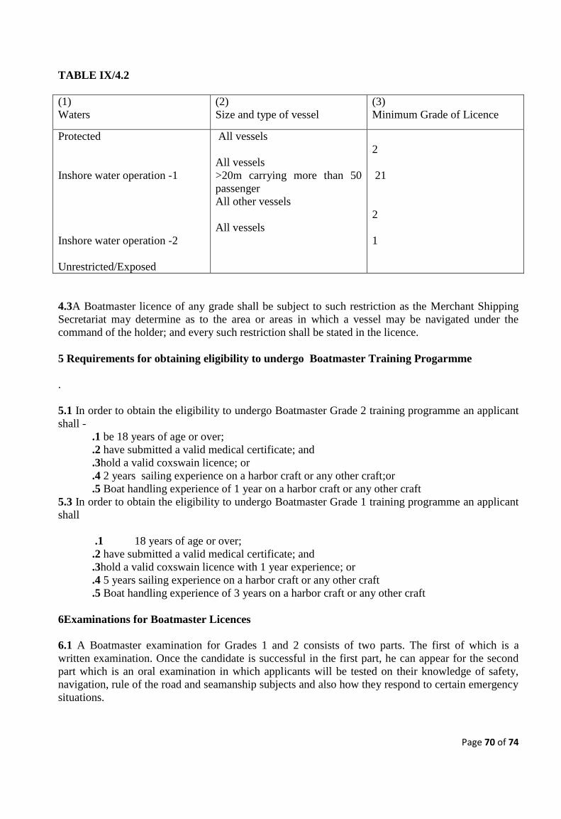
Page 70 of 74
TABLE IX/4.2
(1)
Waters
(2)
Size and type of vessel
(3)
Minimum Grade of Licence
Protected
Inshore water operation -1
Inshore water operation -2
Unrestricted/Exposed
All vessels
All vessels
>20m carrying more than 50
passenger
All other vessels
All vessels
2
21
2
1
4.3A Boatmaster licence of any grade shall be subject to such restriction as the Merchant Shipping
Secretariat may determine as to the area or areas in which a vessel may be navigated under the
command of the holder; and every such restriction shall be stated in the licence.
5 Requirements for obtaining eligibility to undergo Boatmaster Training Progarmme
.
5.1 In order to obtain the eligibility to undergo Boatmaster Grade 2 training programme an applicant
shall -
.1 be 18 years of age or over;
.2 have submitted a valid medical certificate; and
.3hold a valid coxswain licence; or
.4 2 years sailing experience on a harbor craft or any other craft;or
.5 Boat handling experience of 1 year on a harbor craft or any other craft
5.3 In order to obtain the eligibility to undergo Boatmaster Grade 1 training programme an applicant
shall
.1 18 years of age or over;
.2 have submitted a valid medical certificate; and
.3hold a valid coxswain licence with 1 year experience; or
.4 5 years sailing experience on a harbor craft or any other craft
.5 Boat handling experience of 3 years on a harbor craft or any other craft
6Examinations for Boatmaster Licences
6.1 A Boatmaster examination for Grades 1 and 2 consists of two parts. The first of which is a
written examination. Once the candidate is successful in the first part, he can appear for the second
part which is an oral examination in which applicants will be tested on their knowledge of safety,
navigation, rule of the road and seamanship subjects and also how they respond to certain emergency
situations.

Page 71 of 74
6.2An applicant passing only one part of the examination will be allowed to retain the pass in that
part for the period of validity of the letter of eligibility which is issued prior engage in training
subject to the applicant being the holder of a valid medical fitness certificate when re-sitting the other
part. Details of the syllabus for each grade are contained in Annex 11-1.1.
6.3 All examinations under this code shall be carried out in accordance with the procedure as laid
down in the QMS of the Merchant Shipping Secretariat.
6.4 Applicants who have successfully completed relevant boatmaster training programme are eligible
to sit for the applicable boatmaster licence examination.
7 Grade and Area Restrictions of Boat Engineer Licences
7.1 A licence as engineer issued under sectionIX/3 shall bear the title “Boat Engineer Licence” and
shall be of one of the following grades, which shall be stated in the licence.
Boat Engineer Licence, Grade 1 – between 750kW and 200kW
Boat Engineer Licence, Grade 2 – below 200kW
7.2 The grade of licence appropriate in respect of a vessel when being operated in waters specified in
column (1) of Table IX/7.2, being of the engine power specified in relation to those waters in
column (2) of the Table shall be either that specified in relation to those waters and that size of vessel
in column (3) of the Table or, where the grade so specified is 2, a higher grade than that so specified:
TABLE IX/7.2
(1)
Waters
(2)
Engine power
(3)
Minimum Grade of Licence
Protected
Inshore waters
Unrestricted/Exposed
<250kW
250 – 750kW
<250kW
250 – 750kW
<250kW
250 – 750kW
2
1
2
1
2
1

Page 72 of 74
7.3A person required to hold a Boat Engineer Licence on a passenger vessel must also have
completed six months service whilst holding the appropriate certificate.
8 Requirements for obtaining a Boat Engineer Licence
In order to obtain a Boat Engineer Licence an applicant shall -
.1 be eighteen years of age or over;
.2 have completed an approved course on the repair and maintenance of engines and
associated systems on seagoing vessels;
.3 have submitted a valid medical certificate;
.4 produce documentary evidence of having obtained the additional qualifications stated in
Annex 11-1.2.1; and
.5 have passed anassessment for Boat Engineer.
9 Approved Course
9.1 An approved course is a course to the satisfaction of the Merchant Shipping Secretariat, which
covers the syllabus given in Annex 11-2. A Certificate of Attendance will be given by anapproved
training institute to persons satisfactorily completing the course.
9.2 Persons who are able to demonstrate to the satisfaction of the Merchant Shipping Secretariat that
they have appropriate engineering experience may be granted an exemption from the requirement to
attend an approved course.
10 Examination for Boat Engineer Licences
10.1 A Boat Engineer examination for Grades 1 and 2 consists of two parts. The first of which is a
written examination. Once the candidate is successful in the first part, he can appear for the second
part which isan oral examination in which applicants shall be tested on their knowledge of marine
engines, propulsion systems, auxiliary machinery systems outboard engines, safe working practices
and how the candidate responds to certain emergency situations.
10.2 An applicant passing only one part of the examination will be allowed to retain the pass in that
part for the period of validity of the letter of eligibility which is issued prior engage in training
subject to the applicant being the holder of a valid medical fitness certificate when re-sitting the other
part.The examination for a Boat Engineer Licence shall be based on the syllabus given in Annex 11-
2 at a level appropriate to the Grade of Licence applied for and its range of application.
10.3 All examinations under this code shall be carried out in accordance with the procedures laid
down in the QMS of the Merchant Shipping Secretariat.
11 Existing licences
11.1 Subject to IX/11.2, the standards of competence to be attained and the conditions to be satisfied
by the holder of an existing licence to operate commercial vessels in order for a licence to be issued
to that person under this Chapter, shall be such standards and conditions as were to be satisfied by
that person in order for the existing licence to be issued. Accordingly, the Merchant Shipping
Secretariat shall on the application of the holder of an existing licence issue to that person a licence
under this Chapter; and the licence shall -
.1 be of the grade which is appropriate in respect of -
.1 a vessel when being navigated/operated in waters in the area or areas stated in the
existing licence as the area or areas of operation; and
.2 the size of vessel which in the period of 12 months before the coming into force of
the Code was navigated/operated in that area under the command or charge of the
holder of the existing licence; and

Page 73 of 74
.2 state the area or areas in which a vessel may be navigated/operated under the command or
charge of the holder, as the area or areas stated in the existing licence as the area or areas of
operation.
11.2 A person to be issued a licence under IX/11.1 must hold the additional qualifications identified
in Annex 11 paragraph 1.2 and have appropriate knowledge of the Code, to the satisfaction of the
Merchant Shipping Secretariat.
12 Period of Validity and Renewal of Licence
12.1 Licences shall be subject to re-validation every 5 years. Revalidation is also subject to the
submission of a medical certificate in accordance with sectionIX/13.
12.2 Applicants unable to provide proof of service required by IX/12.1 shall satisfy the Merchant
Shipping Secretariat of continued professional competence through an assessment.
13 Medical Fitness Certificate
A medical fitness certificate issued in accordance with the section A-1/9 of the STCW code shall be
submitted with the initial application for a Boatmaster or Boat Engineer licence and for the re-
validation of a licence.
14 Record and surrender of licences
14.1 The Merchant Shipping Secretariat shall make and, during the period of the licence, retain a
copy of every licence issued under this Chapter.
14.2 A record of-
.1 every licence issued under this Part;
.2 every suspension, cancellation or alteration of and any other matter affecting such a
licence;
shall be kept, in such manner as the Merchant Shipping Secretariat may require.
PART B - HOURS OF WORK
15 Working Hours
15.1 References to a person being on duty are references-
.1 in the case of a boatmaster who has command of a vessel in the course of his employment,
to being on duty, whether for the purpose of having the command of a vessel to which this
Chapter applies or for other purposes, in the employment of the person who employs him in
that employment or in any other employment under that person; and
.2 in the case of a boatmaster who has command of a vessel for the purposes of a trade or
business carried on by him, having command of a vessel to which this Chapter applies for the
purposes of that trade or business or being otherwise engaged in work for the purposes of that
trade or business, being work in connection with such a vessel or the passengers carried by it.
15.2 A boatmaster shall so far as is reasonably practicable ensure that he or she is properly rested
when first going on duty on any working day.
15.3 Subject to IX/15.7, the working day of a boatmaster shall not exceed 16 hours.
15.4 Subject to IX/15.7, a boatmaster shall not on any working day con a vessel or vessels to which
the Code applies for periods amounting in the aggregate to more than 10 hours.
15.5 Subject to IX/15.7, where on any working day a boatmaster has been on duty-

Page 74 of 74
.1 for a period of 6 hours and the end of that period does not mark the end of the working day;
or
.2 for periods amounting in the aggregate to 6 hours and there has not been between any of
those periods an interval of not less than 30 minutes in which the boatmaster was able to
obtain rest and refreshment and the end of the last of those periods does not mark the end of
the working day;
there shall be an interval for rest -
.1 as respects the period mentioned in .1 above, at the end of that period; or
.2 in the case of the periods mentioned in .2 above, at the end of the last of those periods.
15.6 Subject to IX/15.7 there shall be, between any two successive working days of a boatmaster, an
interval for rest which shall not be of less than 8 hours; and, in the case of a boatmaster who has
command of a vessel in the course of his employment, a period of time shall not be treated as not
being an interval for rest by reason only that he may be called upon to report for duty if required.
15.7 Where the Merchant Shipping Secretariat considers that it would be appropriate to grant an
exemption from all or any of the requirements of IX/15.3 to IX/15.6, it may on such terms, if any, as
maybe specified grant such an exemption; and, subject to giving reasonable notice, the Merchant
Shipping Secretariat may alter or cancel an exemption so granted.
15.8 The provisions of IX/15.3 to 15.6 apply to vessels operating in protected and inshore waters.
The working hours of seafarers on vessels operating in exposed waters and unrestricted waters shall
be determined by the relevant provisions of the International Convention on Standards of Training,
Certification and Watchkeeping for Seafarers, 1978 as amended.
PART C -MANNING
16 Minimum Manning
16.1 Minimum manning level for each vessel under this code will be specified in the certificate of
survey. It shall be the duty of an owner of a vessel to which this section applies to propose the
manning level in writing to the Merchant Shipping Secretariat and seek approval.
16.2A vessel to which this section applies shall not proceed on a voyage or excursion unless-
.1the manning of the vessel is in accordance with the certificate of survey.
CHAPTER X – AMENDMENTS TO THE SCV CODE
1. The Director General of Merchant Shipping may amend from time to time the provisions of this
code on the recommendation of the panel of experts appointed under the section 2 of this chapter.
2. There shall be a panel of experts appointed by the Director General of Merchant Shipping to
advise him on the matters constitute under this code and the panel shall consist of professionals who
have knowledge and experience in the field of navigation, Marine engineering and Naval
architecture.
3.It shall be the function of the panel to review the code on the advice of the Director General in
accordance with International standards and provisions of international conventions and to make
recommendation to the Director General of Merchant Shipping on which provisions should be
amended in the code or any interpretation which needed on provisions of this code.
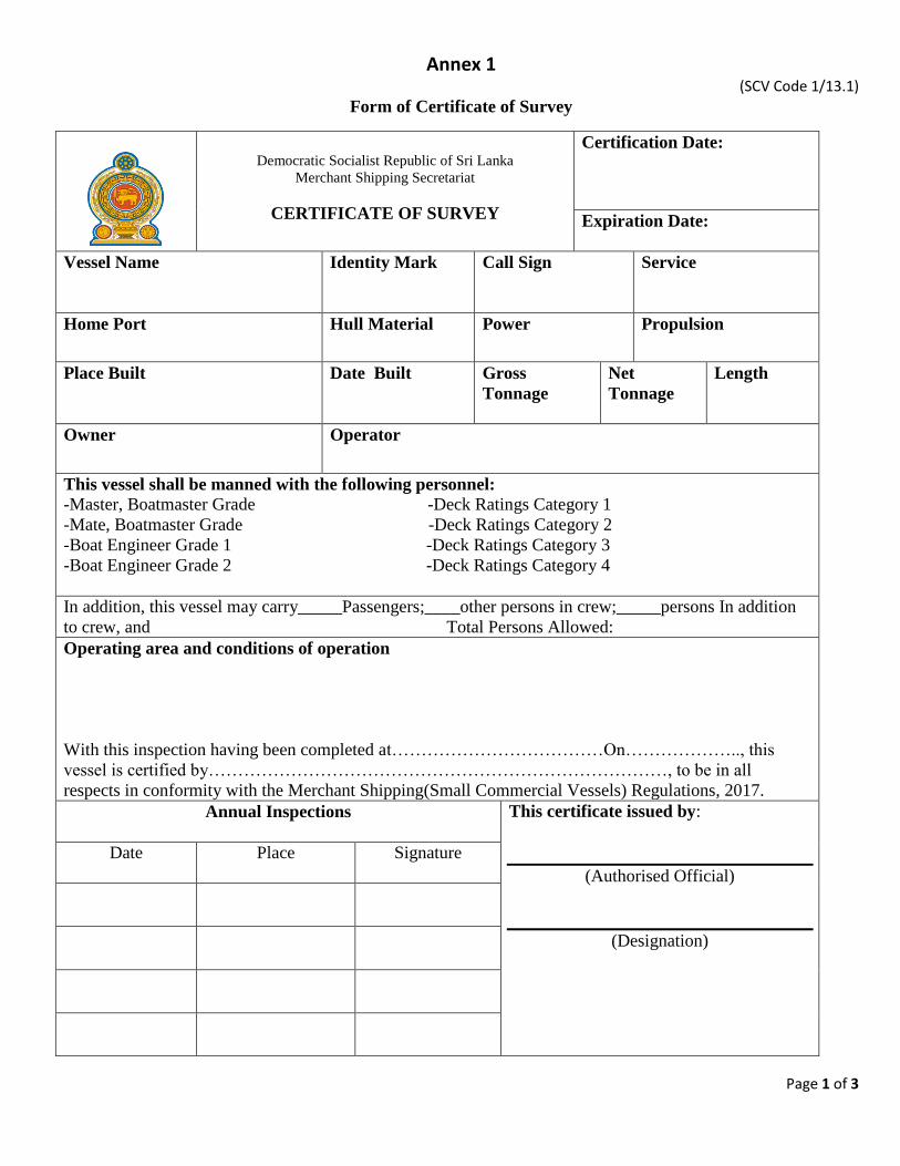
Page 1 of 3
Annex 1 (SCV Code 1/13.1)
Form of Certificate of Survey
Democratic Socialist Republic of Sri Lanka
Merchant Shipping Secretariat
CERTIFICATE OF SURVEY
Certification Date:
Expiration Date:
Vessel Name
Identity Mark Call Sign Service
Home Port Hull Material Power Propulsion
Place Built Date Built Gross
Tonnage
Net
Tonnage
Length
Owner
Operator
This vessel shall be manned with the following personnel:
-Master, Boatmaster Grade -Deck Ratings Category 1
-Mate, Boatmaster Grade -Deck Ratings Category 2
-Boat Engineer Grade 1 -Deck Ratings Category 3
-Boat Engineer Grade 2 -Deck Ratings Category 4
In addition, this vessel may carry_____Passengers;____other persons in crew;_____persons In addition
to crew, and Total Persons Allowed:
Operating area and conditions of operation
With this inspection having been completed at………………………………On……………….., this
vessel is certified by……………………………………………………………………, to be in all
respects in conformity with the Merchant Shipping(Small Commercial Vessels) Regulations, 2017.
Annual Inspections
This certificate issued by:
(Authorised Official)
(Designation)
Date
Place Signature
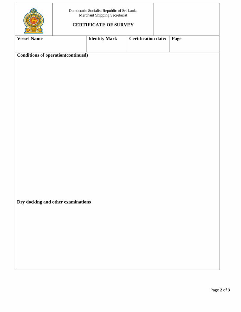
Page 2 of 3
Democratic Socialist Republic of Sri Lanka
Merchant Shipping Secretariat
CERTIFICATE OF SURVEY
Vessel Name
Identity Mark Certification date: Page
Conditions of operation(continued)
Dry docking and other examinations
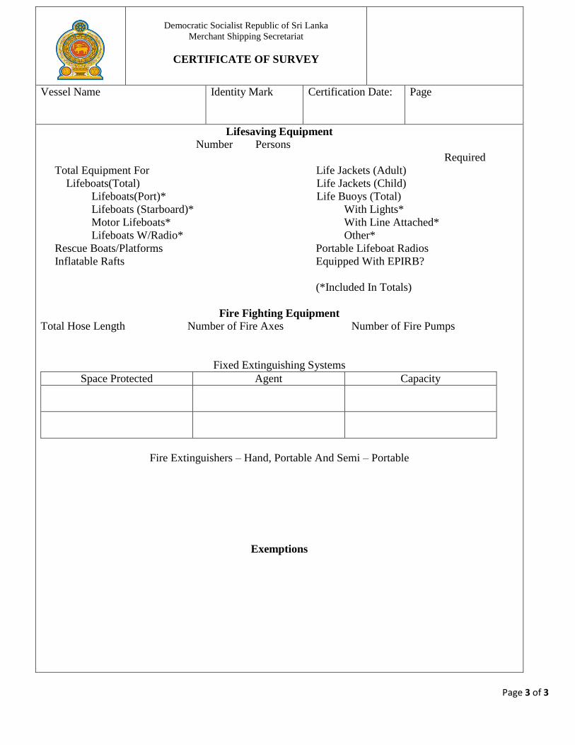
Page 3 of 3
Democratic Socialist Republic of Sri Lanka
Merchant Shipping Secretariat
CERTIFICATE OF SURVEY
Vessel Name
Identity Mark Certification Date: Page
Lifesaving Equipment
Number Persons
Required
Total Equipment For Life Jackets (Adult)
Lifeboats(Total) Life Jackets (Child)
Lifeboats(Port)* Life Buoys (Total)
Lifeboats (Starboard)* With Lights*
Motor Lifeboats* With Line Attached*
Lifeboats W/Radio* Other*
Rescue Boats/Platforms Portable Lifeboat Radios
Inflatable Rafts Equipped With EPIRB?
(*Included In Totals)
Fire Fighting Equipment
Total Hose Length Number of Fire Axes Number of Fire Pumps
Fixed Extinguishing Systems
Space Protected Agent Capacity
Fire Extinguishers – Hand, Portable And Semi – Portable
Exemptions
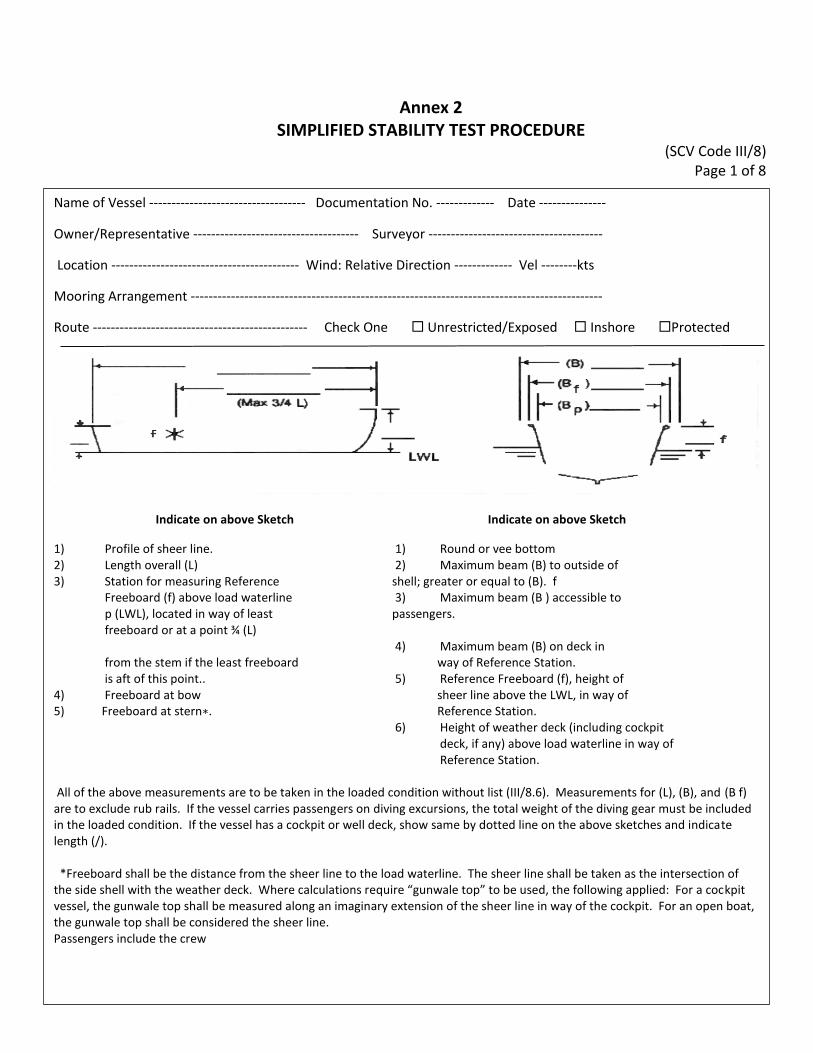
Annex 2 SIMPLIFIED STABILITY TEST PROCEDURE
(SCV Code III/8) Page 1 of 8
Name of Vessel ----------------------------------- Documentation No. ------------- Date ---------------
Owner/Representative ------------------------------------- Surveyor ---------------------------------------
Location ------------------------------------------ Wind: Relative Direction ------------- Vel --------kts
Mooring Arrangement --------------------------------------------------------------------------------------------
Route ------------------------------------------------ Check One Unrestricted/Exposed Inshore Protected
Indicate on above Sketch Indicate on above Sketch
1) Profile of sheer line. 1) Round or vee bottom 2) Length overall (L) 2) Maximum beam (B) to outside of 3) Station for measuring Reference shell; greater or equal to (B). f
Freeboard (f) above load waterline 3) Maximum beam (B ) accessible to p (LWL), located in way of least passengers. freeboard or at a point ¾ (L)
4) Maximum beam (B) on deck in from the stem if the least freeboard way of Reference Station. is aft of this point.. 5) Reference Freeboard (f), height of
4) Freeboard at bow sheer line above the LWL, in way of 5) Freeboard at stern∗. Reference Station.
6) Height of weather deck (including cockpit deck, if any) above load waterline in way of Reference Station.
All of the above measurements are to be taken in the loaded condition without list (III/8.6). Measurements for (L), (B), and (B f) are to exclude rub rails. If the vessel carries passengers on diving excursions, the total weight of the diving gear must be included in the loaded condition. If the vessel has a cockpit or well deck, show same by dotted line on the above sketches and indicate length (/). *Freeboard shall be the distance from the sheer line to the load waterline. The sheer line shall be taken as the intersection of the side shell with the weather deck. Where calculations require “gunwale top” to be used, the following applied: For a cockpit vessel, the gunwale top shall be measured along an imaginary extension of the sheer line in way of the cockpit. For an open boat, the gunwale top shall be considered the sheer line. Passengers include the crew
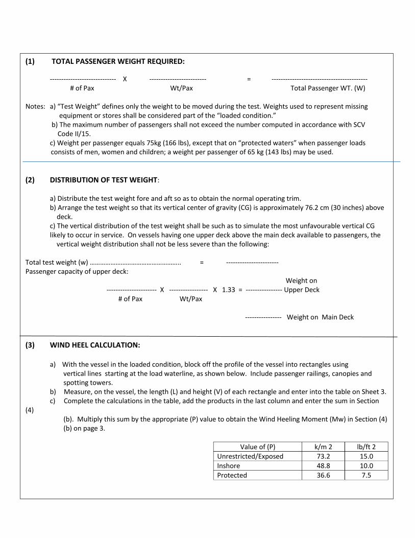
(1) TOTAL PASSENGER WEIGHT REQUIRED:
----------------------------- X ------------------------- = ------------------------------------------ # of Pax Wt/Pax Total Passenger WT. (W)
Notes: a) “Test Weight” defines only the weight to be moved during the test. Weights used to represent missing equipment or stores shall be considered part of the “loaded condition.” b) The maximum number of passengers shall not exceed the number computed in accordance with SCV Code II/15. c) Weight per passenger equals 75kg (166 lbs), except that on “protected waters” when passenger loads consists of men, women and children; a weight per passenger of 65 kg (143 lbs) may be used.
(2) DISTRIBUTION OF TEST WEIGHT:
a) Distribute the test weight fore and aft so as to obtain the normal operating trim. b) Arrange the test weight so that its vertical center of gravity (CG) is approximately 76.2 cm (30 inches) above deck. c) The vertical distribution of the test weight shall be such as to simulate the most unfavourable vertical CG likely to occur in service. On vessels having one upper deck above the main deck available to passengers, the vertical weight distribution shall not be less severe than the following:
Total test weight (w) …………………………………………….. = ----------------------- Passenger capacity of upper deck: Weight on ---------------------- X ----------------- X 1.33 = ---------------- Upper Deck # of Pax Wt/Pax ---------------- Weight on Main Deck
(3) WIND HEEL CALCULATION:
a) With the vessel in the loaded condition, block off the profile of the vessel into rectangles using vertical lines starting at the load waterline, as shown below. Include passenger railings, canopies and spotting towers. b) Measure, on the vessel, the length (L) and height (V) of each rectangle and enter into the table on Sheet 3. c) Complete the calculations in the table, add the products in the last column and enter the sum in Section
(4) (b). Multiply this sum by the appropriate (P) value to obtain the Wind Heeling Moment (Mw) in Section (4) (b) on page 3.
Value of (P) k/m 2 lb/ft 2
Unrestricted/Exposed 73.2 15.0
Inshore 48.8 10.0
Protected 36.6 7.5

(3) continued -profile-
Load Waterline Scale:1 SQUARE = ____________________
-Calculations-
Section L Y A (L*V)
H (0.5v)
A*H
A
B
C
D
E
F
G
Sum (A*H)
(4) REQUIRED HEELING MOMENT: Apply ( a ) or ( b), whichever is greater: (a) Passenger Heeling Moment (Mp) = (W X Bp)/6 = ( ------------------------------------ X ---------------------------------)/6 = --------------------------------- Total Passenger Wt. (W) Max Beam Open Passengers (Bp) (b) Wind Heeling Moment (Mw ) = -------------------------------------- X ------------------------------------ = --------------------------------- Wind Pressure (P) Sum (A x H )
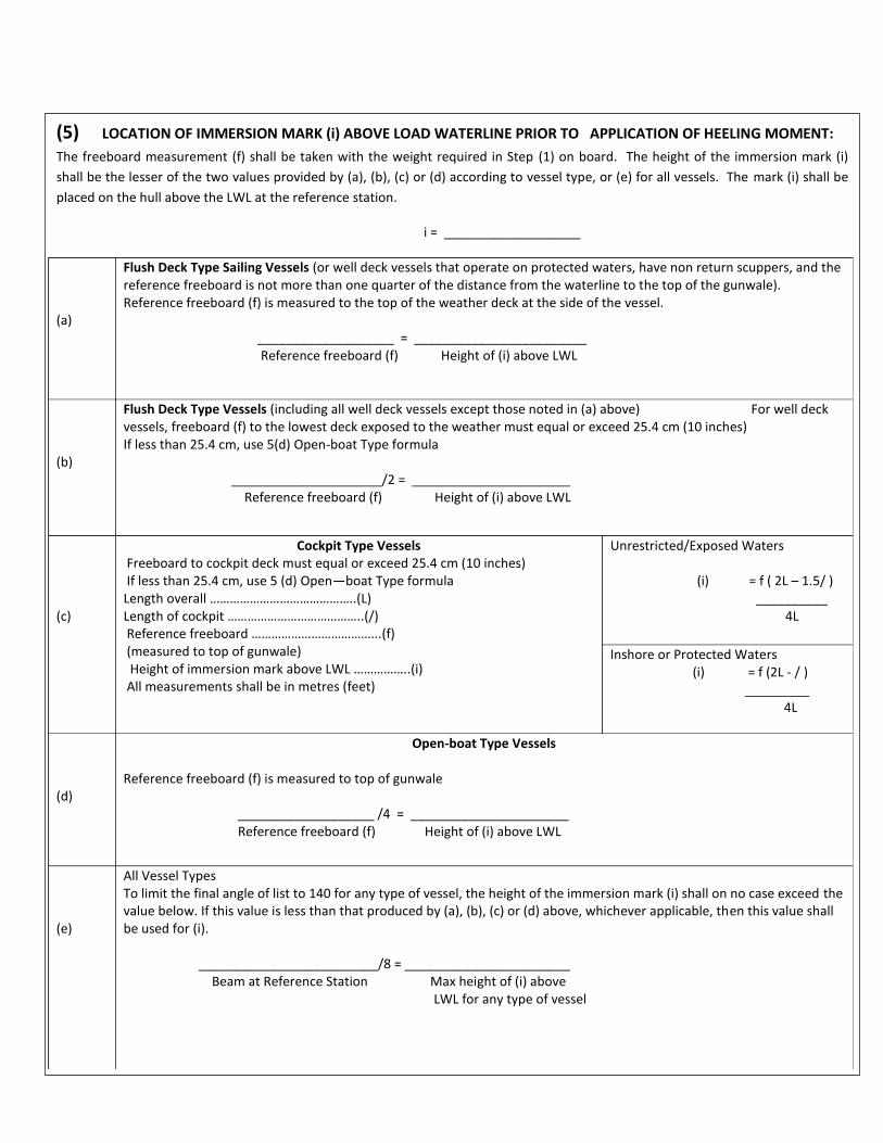
(5) LOCATION OF IMMERSION MARK (i) ABOVE LOAD WATERLINE PRIOR TO APPLICATION OF HEELING MOMENT:
The freeboard measurement (f) shall be taken with the weight required in Step (1) on board. The height of the immersion mark (i)
shall be the lesser of the two values provided by (a), (b), (c) or (d) according to vessel type, or (e) for all vessels. The mark (i) shall be
placed on the hull above the LWL at the reference station.
i = ___________________
(a)
Flush Deck Type Sailing Vessels (or well deck vessels that operate on protected waters, have non return scuppers, and the reference freeboard is not more than one quarter of the distance from the waterline to the top of the gunwale). Reference freeboard (f) is measured to the top of the weather deck at the side of the vessel. ___________________ = ________________________ Reference freeboard (f) Height of (i) above LWL
(b)
Flush Deck Type Vessels (including all well deck vessels except those noted in (a) above) For well deck vessels, freeboard (f) to the lowest deck exposed to the weather must equal or exceed 25.4 cm (10 inches) If less than 25.4 cm, use 5(d) Open-boat Type formula _____________________/2 = ______________________ Reference freeboard (f) Height of (i) above LWL
(c)
Cockpit Type Vessels Freeboard to cockpit deck must equal or exceed 25.4 cm (10 inches) If less than 25.4 cm, use 5 (d) Open—boat Type formula Length overall ……………………………………..(L) Length of cockpit …………………………………..(/) Reference freeboard ………………………………...(f) (measured to top of gunwale) Height of immersion mark above LWL ……………..(i) All measurements shall be in metres (feet)
Unrestricted/Exposed Waters
(i) = f ( 2L – 1.5/ ) __________ 4L
Inshore or Protected Waters (i) = f (2L - / )
_________ 4L
(d)
Open-boat Type Vessels Reference freeboard (f) is measured to top of gunwale ___________________ /4 = ______________________ Reference freeboard (f) Height of (i) above LWL
(e)
All Vessel Types To limit the final angle of list to 140 for any type of vessel, the height of the immersion mark (i) shall on no case exceed the value below. If this value is less than that produced by (a), (b), (c) or (d) above, whichever applicable, then this value shall be used for (i). _________________________/8 = _______________________ Beam at Reference Station Max height of (i) above LWL for any type of vessel
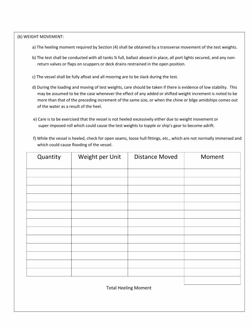
(6) WEIGHT MOVEMENT:
a) The heeling moment required by Section (4) shall be obtained by a transverse movement of the test weights.
b) The test shall be conducted with all tanks ¾ full, ballast aboard in place, all port lights secured, and any non-
return valves or flaps on scuppers or deck drains restrained in the open position.
c) The vessel shall be fully afloat and all mooring are to be slack during the test.
d) During the loading and moving of test weights, care should be taken if there is evidence of low stability. This
may be assumed to be the case whenever the effect of any added or shifted weight increment is noted to be
more than that of the preceding increment of the same size, or when the chine or bilge amidships comes out
of the water as a result of the heel.
e) Care is to be exercised that the vessel is not heeled excessively either due to weight movement or
super imposed roll which could cause the test weights to topple or ship’s gear to become adrift.
f) While the vessel is heeled, check for open seams, loose hull fittings, etc., which are not normally immersed and
which could cause flooding of the vessel.
Quantity
Weight per Unit Distance Moved Moment
Total Heeling Moment
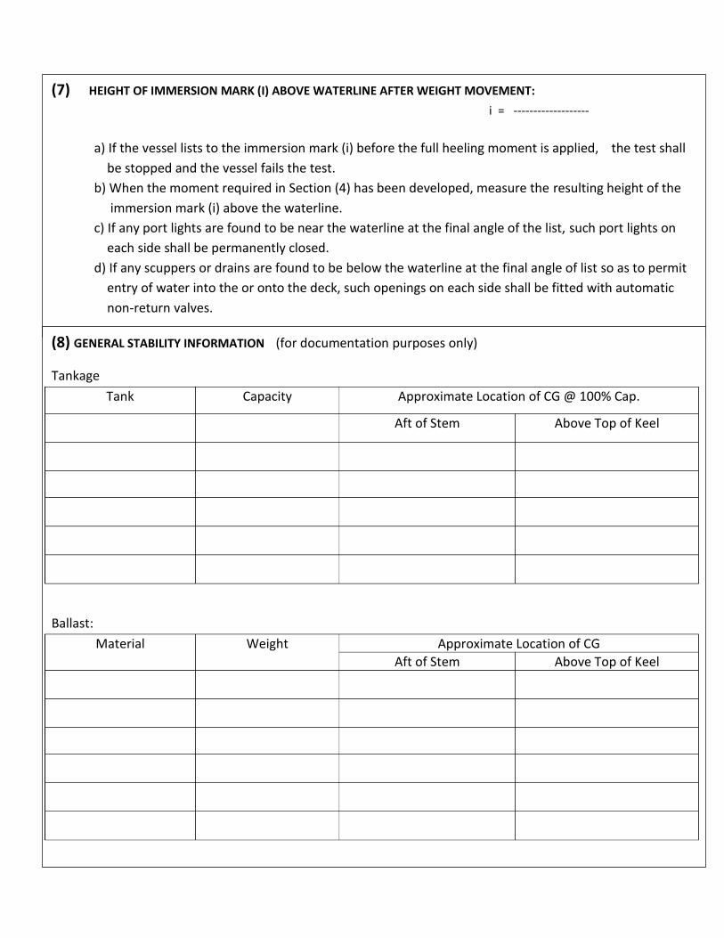
(7) HEIGHT OF IMMERSION MARK (I) ABOVE WATERLINE AFTER WEIGHT MOVEMENT:
i = -------------------
a) If the vessel lists to the immersion mark (i) before the full heeling moment is applied, the test shall
be stopped and the vessel fails the test.
b) When the moment required in Section (4) has been developed, measure the resulting height of the
immersion mark (i) above the waterline.
c) If any port lights are found to be near the waterline at the final angle of the list, such port lights on
each side shall be permanently closed.
d) If any scuppers or drains are found to be below the waterline at the final angle of list so as to permit
entry of water into the or onto the deck, such openings on each side shall be fitted with automatic
non-return valves.
(8) GENERAL STABILITY INFORMATION (for documentation purposes only)
Tankage
Tank Capacity Approximate Location of CG @ 100% Cap.
Aft of Stem Above Top of Keel
Ballast:
Material Weight Approximate Location of CG
Aft of Stem Above Top of Keel

TWENTY-FIVE PERCENT TEST Page 7 of 8
(This test is not a necessary part of the Simplified Stability Test Procedure but may be used as a preliminary Check when the stability is believed to be marginal)
1. After the Total Test Weight (W) has been placed on board and the Reference Freeboard (f) has
been measured, rig a pendulum free to swing athwartships at any convenient location on the vessel. Arrange it so that the bob is approximately 3 mm (1/8 inch) above the deck. Place a chalk mark on the deck directly beneath the bob. Measure the pendulum length (pend. 1) as the distance from pivot to deck.
2. Move the test weight to obtain a heeling moment equal to one-quarter of the Required Heeling Moment in Section (4) on page 3. It is suggested that the weights having the longest levers be moved as to minimize the amount of weight handled.
3. After the weight has been moved, place a chalk mark on the deck directly beneath the
pendulum bob. Measure the pendulum deflection (pend. D.) as the distance between chalk marks.
4. Before proceeding with the Simplified Stability Test Procedure, the following calculations may
be carried out to anticipate the results:
Approximate Maximum allowable Heeling Moment: 2 X ------------------ X ------------------- X ------------------ ¼ H.M pend. 1. Height of (i) = ---------- ----------------------- X ------------------------------- pend.d. Beam at Ref. Station (Bf) If the Maximum Allowable Heeling Moment is LESS than the Required Heeling Moment in Section (4) on page 3, the vessel will probably fail the test by the difference indicated below. Required Heeling Moment = -------------------- Allowance Heeling Moment = -------------------- Difference = ---------------------
If Passenger Heel (4a) applies Approximate Number of Passengers in Excess 6 x ___________ Difference = ___________ #of Pax ______________X __________ Wt/Pax (Bp)
If Wind Heel (4b) applies: Approximate Excess Wind Moment ( Sum A x H ) ------------------ / ------------ = --------- Difference ( P ) Moment
One – quarter
Heeling Moment: --------------------------- /4 = ---------------------------
Req’d H.M. (4)

STABILITY TEST PROCEDURE
FOR VESSELS CARRYING PASSENGERS AND CARGO
(1) For vessels carrying cargo as well as passengers, follow the same test procedure as for vessels carrying
passengers alone except that, in addition to the passenger test weight, the maximum deadweight of
cargo permitted shall be on board, in place and so arranged as to simulate the most unfavourable
vertical center of gravity likely to occur in service.
(2) Specify the maximum cargo deadweight permitted to be carried:
Weight of Cargo Approximate Location of CG
Aft of Stem Above Top of Keel
(3) Complete the Twenty-Five Percent Test based on the Passenger Heeling Moment or the Wind Heeling
Moment, whichever is applicable, and note the anticipated test results.
(4) If the anticipated results of the test indicate that the vessel will fail, the entire test must be repeated
with a reduced number of passengers and/or a reduced amount of cargo, or by utilizing any other
corrective measures available.
(5) If the anticipated results of the test indicates that the vessel will pass, then with he vessel in the
heeled condition and being cautious not to disturb any of the test weights which were shifted in order
to heel the vessel; remove approximately one-quarter of the cargo from the vessel exercising great
care to remove it symmetrically about the centerline.
(a) If the pendulum deflection DECREASES or remains unchanged -- replace the cargo which was
removed and complete the stability test procedure.
(b) If the pendulum deflection INCREASES -- the cargo may be improving the stability of the
vessel. Therefore, remove all of the cargo from the vessel, replace the test weights in their
original positions so as to remove all list, re measure the Reference Freeboard (f), and repeat
the Twenty-Five Percent Test in its entirety for the new condition of loading. If the second
Twenty-Five Percent Test indicates that the vessel will pass, complete the stability test
procedure.
(6) If the vessel passes the stability test procedure under these conditions, it is deemed to have adequate
stability for the safe carriage of passengers allowed regardless of whether or not cargo, not in excess
of the amount specified in item (2) above, is carried.
ANNEX 2(A)
STABILITY INFORMATION
(SCV Code III/Part B/5.1) 1 Sheet
The Format of the stability booklet and the information included will vary dependent on the vessel type and operation. Units of measure used in the stability booklet must agree with the units of measure of the draft markings.
In developing the stability booklet, consideration must be given to the following information:
.1 A general description of the vessel, including lightweight data.
.2 Instructions on the use of the booklet.
.3 General arrangement plans showing watertight compartments, closures, vents, downflooding angles, and allowable deck loadings. .4 Hydrostatic curves or tables. .5 Capacity plan showing capacities and vertical, longitudinal centers of gravity of stowage spaces and tanks. .6 Tank sounding tables showing capacities, vertical centers of gravity in graduated intervals and showing free surface data for each tank. .7 Information on loading restrictions, such as a maximum KG of minimum GM curve that can be used to determine compliance with applicable intact and damage stability criteria. .8 Examples of loading conditions.
.9 A rapid and simple means for evaluating other loading conditions.
.10 A brief description of the stability calculations done including assumptions.
.11 General precautions for preventing unintentional flooding.
.12 A table of contents and index for the booklet.
.13 Each ship condition which, if damage occurs, may require cross-flooding for survival and information concerning the use of any special cross-flooding fittings. .14 The mount and location of fixed ballast.
.15 Any other necessary guidance for the safe operation of the vessel under normal and emergency conditions. .16 For each self propelled hopper dredge with a working freeboard, the maximum specific gravity allowed for dredge spoil.
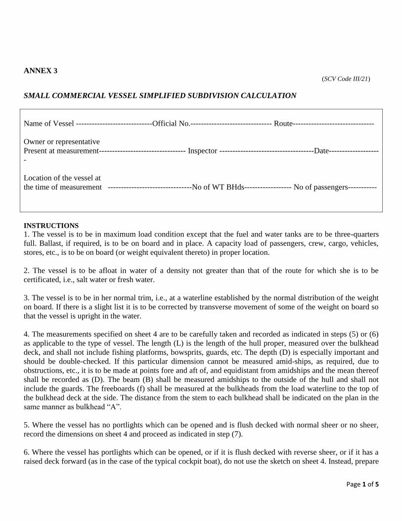
Page 1 of 5
ANNEX 3 (SCV Code III/21)
SMALL COMMERCIAL VESSEL SIMPLIFIED SUBDIVISION CALCULATION
Name of Vessel -----------------------------Official No.------------------------------- Route-------------------------------
Owner or representative
Present at measurement--------------------------------- Inspector ------------------------------------Date-------------------
-
Location of the vessel at
the time of measurement --------------------------------No of WT BHds------------------ No of passengers-----------
INSTRUCTIONS
1. The vessel is to be in maximum load condition except that the fuel and water tanks are to be three-quarters
full. Ballast, if required, is to be on board and in place. A capacity load of passengers, crew, cargo, vehicles,
stores, etc., is to be on board (or weight equivalent thereto) in proper location.
2. The vessel is to be afloat in water of a density not greater than that of the route for which she is to be
certificated, i.e., salt water or fresh water.
3. The vessel is to be in her normal trim, i.e., at a waterline established by the normal distribution of the weight
on board. If there is a slight list it is to be corrected by transverse movement of some of the weight on board so
that the vessel is upright in the water.
4. The measurements specified on sheet 4 are to be carefully taken and recorded as indicated in steps (5) or (6)
as applicable to the type of vessel. The length (L) is the length of the hull proper, measured over the bulkhead
deck, and shall not include fishing platforms, bowsprits, guards, etc. The depth (D) is especially important and
should be double-checked. If this particular dimension cannot be measured amid-ships, as required, due to
obstructions, etc., it is to be made at points fore and aft of, and equidistant from amidships and the mean thereof
shall be recorded as (D). The beam (B) shall be measured amidships to the outside of the hull and shall not
include the guards. The freeboards (f) shall be measured at the bulkheads from the load waterline to the top of
the bulkhead deck at the side. The distance from the stem to each bulkhead shall be indicated on the plan in the
same manner as bulkhead “A”.
5. Where the vessel has no portlights which can be opened and is flush decked with normal sheer or no sheer,
record the dimensions on sheet 4 and proceed as indicated in step (7).
6. Where the vessel has portlights which can be opened, or if it is flush decked with reverse sheer, or if it has a
raised deck forward (as in the case of the typical cockpit boat), do not use the sketch on sheet 4. Instead, prepare
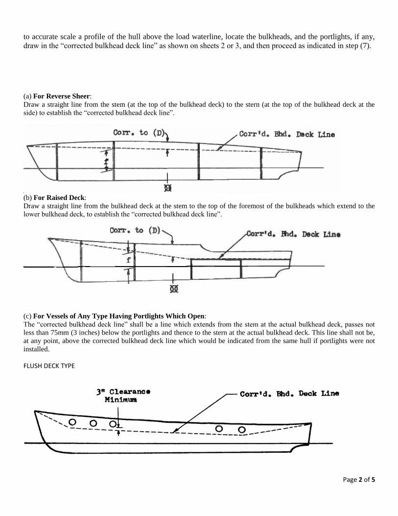
Page 2 of 5
to accurate scale a profile of the hull above the load waterline, locate the bulkheads, and the portlights, if any,
draw in the “corrected bulkhead deck line” as shown on sheets 2 or 3, and then proceed as indicated in step (7).
(a) For Reverse Sheer:
Draw a straight line from the stem (at the top of the bulkhead deck) to the stern (at the top of the bulkhead deck at the
side) to establish the “corrected bulkhead deck line”.
(b) For Raised Deck:
Draw a straight line from the bulkhead deck at the stem to the top of the foremost of the bulkheads which extend to the
lower bulkhead deck, to establish the “corrected bulkhead deck line”.
(c) For Vessels of Any Type Having Portlights Which Open:
The “corrected bulkhead deck line” shall be a line which extends from the stem at the actual bulkhead deck, passes not
less than 75mm (3 inches) below the portlights and thence to the stern at the actual bulkhead deck. This line shall not be,
at any point, above the corrected bulkhead deck line which would be indicated from the same hull if portlights were not
installed.
FLUSH DECK TYPE
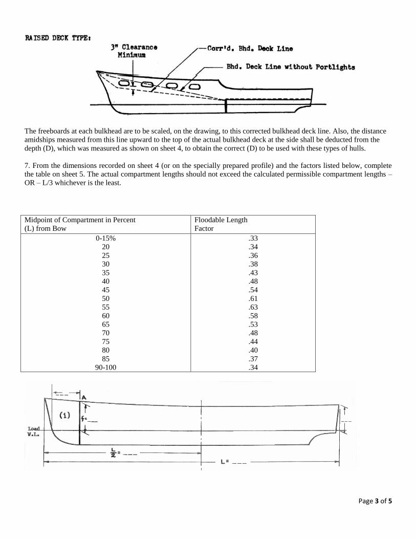
Page 3 of 5
The freeboards at each bulkhead are to be scaled, on the drawing, to this corrected bulkhead deck line. Also, the distance
amidships measured from this line upward to the top of the actual bulkhead deck at the side shall be deducted from the
depth (D), which was measured as shown on sheet 4, to obtain the correct (D) to be used with these types of hulls.
7. From the dimensions recorded on sheet 4 (or on the specially prepared profile) and the factors listed below, complete
the table on sheet 5. The actual compartment lengths should not exceed the calculated permissible compartment lengths –
OR – L/3 whichever is the least.
Midpoint of Compartment in Percent
(L) from Bow Floodable Length
Factor
0-15%
20
25
30
35
40
45
50
55
60
65
70
75
80
85
90-100
.33
.34
.36
.38
.43
.48
.54
.61
.63
.58
.53
.48
.44
.40
.37
.34

Page 4 of 5
1. Draw in other W.T. bulkheads. Indicate distance from stem and freeboard for each as shown for
Bulkhead “A”.
2. Freeboards “x” and “y” Amidships must be equal.
3. Record all dimensions in Feet and tenths.
4. Indicate water density at time of measurement.
[] Salt [] Brackish [] Fresh
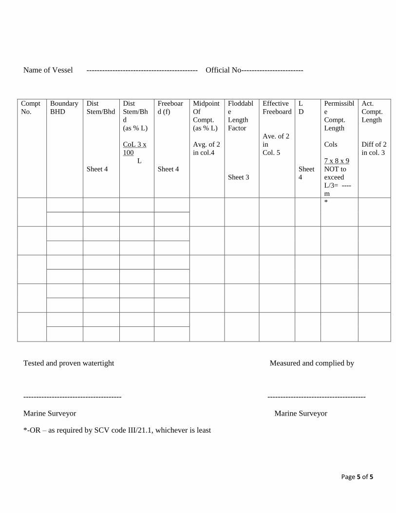
Page 5 of 5
Name of Vessel ------------------------------------------- Official No------------------------
Compt
No.
Boundary
BHD
Dist
Stem/Bhd
Sheet 4
Dist
Stem/Bh
d
(as % L)
CoL 3 x
100
L
Freeboar
d (f)
Sheet 4
Midpoint
Of
Compt.
(as % L)
Avg. of 2
in col.4
Floddabl
e
Length
Factor
Sheet 3
Effective
Freeboard
Ave. of 2
in
Col. 5
L
D
Sheet
4
Permissibl
e
Compt.
Length
Cols
7 x 8 x 9
NOT to
exceed
L/3= ----
m
Act.
Compt.
Length
Diff of 2
in col. 3
*
Tested and proven watertight Measured and complied by
-------------------------------------- --------------------------------------
Marine Surveyor Marine Surveyor
*-OR – as required by SCV code III/21.1, whichever is least
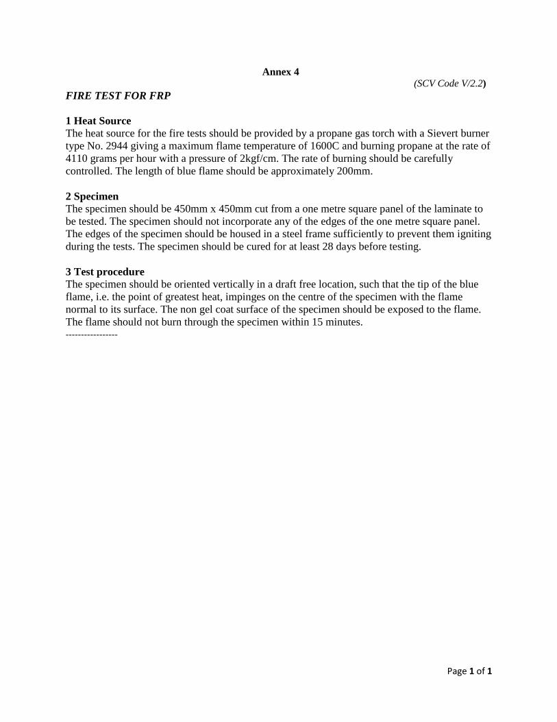
Page 1 of 1
Annex 4 (SCV Code V/2.2)
FIRE TEST FOR FRP
1 Heat Source The heat source for the fire tests should be provided by a propane gas torch with a Sievert burner
type No. 2944 giving a maximum flame temperature of 1600C and burning propane at the rate of
4110 grams per hour with a pressure of 2kgf/cm. The rate of burning should be carefully
controlled. The length of blue flame should be approximately 200mm.
2 Specimen The specimen should be 450mm x 450mm cut from a one metre square panel of the laminate to
be tested. The specimen should not incorporate any of the edges of the one metre square panel.
The edges of the specimen should be housed in a steel frame sufficiently to prevent them igniting
during the tests. The specimen should be cured for at least 28 days before testing.
3 Test procedure The specimen should be oriented vertically in a draft free location, such that the tip of the blue
flame, i.e. the point of greatest heat, impinges on the centre of the specimen with the flame
normal to its surface. The non gel coat surface of the specimen should be exposed to the flame.
The flame should not burn through the specimen within 15 minutes. -----------------
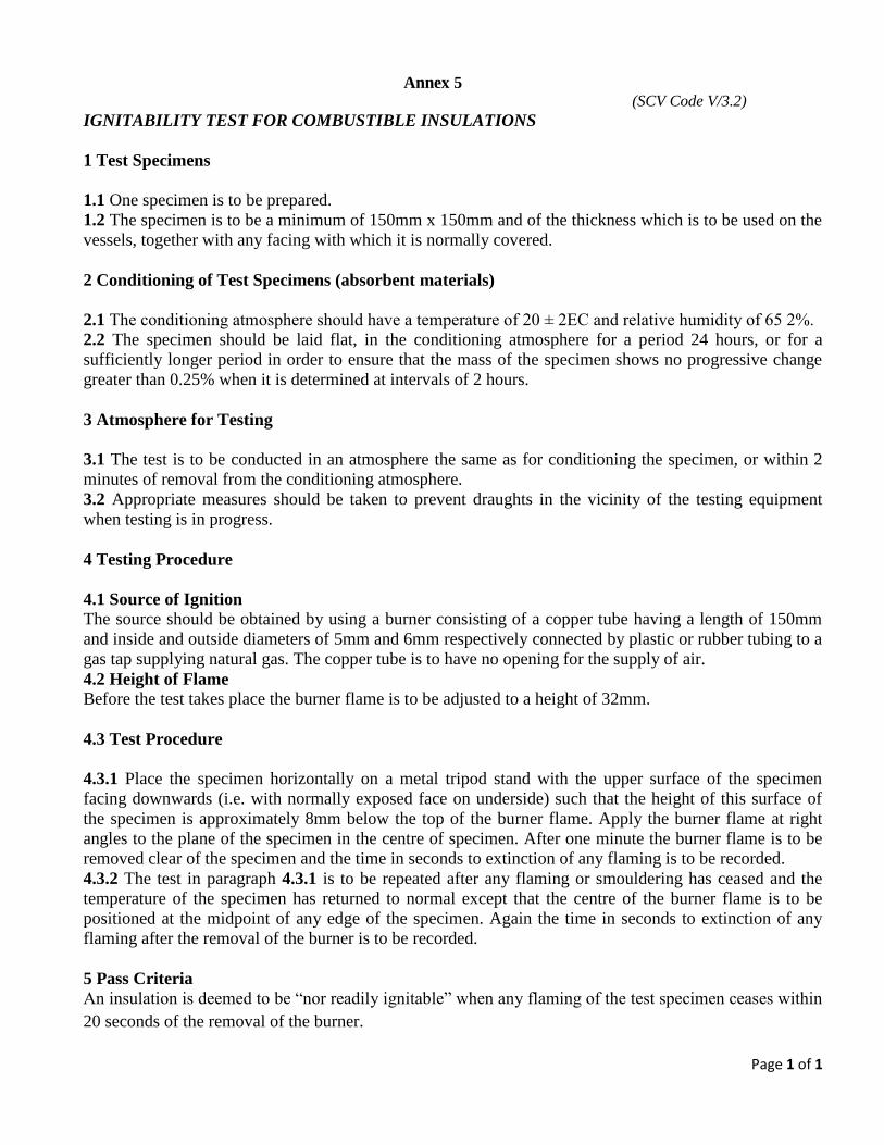
Page 1 of 1
Annex 5 (SCV Code V/3.2)
IGNITABILITY TEST FOR COMBUSTIBLE INSULATIONS
1 Test Specimens
1.1 One specimen is to be prepared.
1.2 The specimen is to be a minimum of 150mm x 150mm and of the thickness which is to be used on the
vessels, together with any facing with which it is normally covered.
2 Conditioning of Test Specimens (absorbent materials)
2.1 The conditioning atmosphere should have a temperature of 20 ± 2ΕC and relative humidity of 65 2%.
2.2 The specimen should be laid flat, in the conditioning atmosphere for a period 24 hours, or for a
sufficiently longer period in order to ensure that the mass of the specimen shows no progressive change
greater than 0.25% when it is determined at intervals of 2 hours.
3 Atmosphere for Testing
3.1 The test is to be conducted in an atmosphere the same as for conditioning the specimen, or within 2
minutes of removal from the conditioning atmosphere.
3.2 Appropriate measures should be taken to prevent draughts in the vicinity of the testing equipment
when testing is in progress.
4 Testing Procedure
4.1 Source of Ignition The source should be obtained by using a burner consisting of a copper tube having a length of 150mm
and inside and outside diameters of 5mm and 6mm respectively connected by plastic or rubber tubing to a
gas tap supplying natural gas. The copper tube is to have no opening for the supply of air.
4.2 Height of Flame Before the test takes place the burner flame is to be adjusted to a height of 32mm.
4.3 Test Procedure
4.3.1 Place the specimen horizontally on a metal tripod stand with the upper surface of the specimen
facing downwards (i.e. with normally exposed face on underside) such that the height of this surface of
the specimen is approximately 8mm below the top of the burner flame. Apply the burner flame at right
angles to the plane of the specimen in the centre of specimen. After one minute the burner flame is to be
removed clear of the specimen and the time in seconds to extinction of any flaming is to be recorded.
4.3.2 The test in paragraph 4.3.1 is to be repeated after any flaming or smouldering has ceased and the
temperature of the specimen has returned to normal except that the centre of the burner flame is to be
positioned at the midpoint of any edge of the specimen. Again the time in seconds to extinction of any
flaming after the removal of the burner is to be recorded.
5 Pass Criteria
An insulation is deemed to be “nor readily ignitable” when any flaming of the test specimen ceases within
20 seconds of the removal of the burner.

Page 1 of 1
Annex 6 (SCV Code VII/5.2)
RECOMMENDED EMERGENCY BROADCAST INSTRUCTIONS
The following emergency broadcast instructions, when placed on a placard, will satisfy the
requirement contained in regulation VII/5.2 for an emergency broadcast placard:
1. Make sure your radiotelephone is on.
2. Select 156.8 MHz (channel 16 VHF) or 2182 kHz. (Channel 16 VHF and 2182 kHz on SSB
are for emergency and calling purposes only).
3. Press microphone button and, speaking slowly – clearly – calmly, say:
.1 “MAYDAY-MAYDAY-MAYDAY” for situations involving Immediate Danger to Life and
Property; or
.2 “PAN-PAN-PAN” for urgent situations where there is No Immediate Danger to Life or
Property.
4. Say: “THIS IS (INSERT VESSEL’S NAME), (INSERT VESSEL’S NAME, (INSERT
VESSEL’S NAME), (INSERT VESSEL’S CALL SIGN), OVER.”
5. Release the microphone button briefly and listen for acknowledgement. If no one answers,
repeat steps 3 & 4.
6. If there is no acknowledgement, or if the Coast Guard or another vessel responds, say:
“MAYDAY” OR “PAN”, (INSERT VESSEL’S NAME).”
7. DESCRIBE YOUR POSITION using latitude and longitude coordinates, LORAN
coordinates, or range and bearing from a known point.
8. STATE THE NATURE OF THE DISTRESS.
9. GIVE NUMBER OR PERSONS ABOARD AND THE NATURE OF ANY INJURIES.
10. ESTIMATE THE PRESENT SEAWORTHINESS OF YOUR VESSEL.
11. BRIEFLY DESCRIBE YOUR VESSEL: (INSERT LENGTH, COLOR, HULL TYPE,
TRIM, MASTS, POWER, AND ADDITIONAL DISTINGUISHING FEATURES).
12. Say: “I WILL BE LISTENING ON CHANNEL 16/2182.”
13. End message by saying: “THIS IS (INSERT VESSEL’S NAME & CALL SIGN).”
14. Where your situation permits stand by the radio to await further communications with the
Coast Guard or another vessel. If no answer, repeat, then try another channel.

Page 1 of 1
Annex 7 (SCV Code VII/7.1)
ANCHORS AND CABLES
Length + Lwl 2
Anchor Mass Anchor Cable Diameter
Main Kedge Main Chain rope
Kedge Chain rope
(metres) (kg) (kg) (mm ) ( mm) (mm) (mm)
6
7
8
9
10
11
12
13
14
15
16
17
18
19
20
21
22
23
24
8
9
10
11
13
15
18
21
24
27
30
34
38
42
47
52
57
62
68
4
4
5
5
6
7
9
10
12
13
15
17
19
21
23
26
28
31
34
6 12
8 12
8 12
8 12
8 12
8 12
8 14
10 14
10 14
10 -
10 -
10 -
10 -
12 -
12 -
12 -
12 -
12 -
12 -
6 10
6 10
6 10
6 10
6 10
6 10
8 12
8 12
8 12
8 12
8 12
8 14
8 14
10 14
10 14
10 14
10 16
10 16
10 16
Notes: 1. The anchor sizes given are for high holding power (HHP) types.
2. When a vessel has unusually high windage due to any combination of high free-board, large
superstructure or deck equipment outfit, the mass of anchor given above shall be increased to take
account of the increase in wind loading.
For vessels of unusual or non-conventional ship form (including pontoon barges) the anchor size shall be
to the satisfaction of the Administration.
The diameter of the anchor cable shall be appropriate to the increased mass of anchor.
3. Chain cable diameter given is for short link chain. Chain cable should be sized in accordance with ISO
4565:1986 - Anchor chains for small craft, or equivalent.
4. The rope diameter given is for nylon construction. When rope of another construction is proposed, the
breaking load should be not less than that of the nylon rope specified in the table.
5. When anchors and cables are manufactured to imperial sizes, the metric equivalent of the anchor mass
and the cable diameter shall not be less than the table value.
6. Lwl is the waterline length of the vessel when the vessel is floating at the assigned free-board draught.

Page 1 of 3
Annex 8
(SCV Code VII/8.2)
FIRST AID KITS
1 Type and Size First-aid kits shall be of the water-tight cabinet carrying type capable of holding the items
specified in paragraph 3.2.
2 Construction and Workmanship The container shall be of substantial and rugged construction, with the body, handle and all
fittings of a corrosion-resistant material or suitably protected against corrosion to the satisfaction
of the Administration.
3 Contents
3.1 Items shall be properly labelled to designate the name of contents and method of use. Each
package shall be enclosed in a jacket of tough, transparent material, properly sealed, which shall
be watertight. Vials for tablets shall not be made of glass.
3.2 The items contained in the first-aid kit shall be as listed in the following Table.
TABLE A8
Items No.
Bandage compress - 4"
Bandage compress - 2"
Waterproof adhesive compress - 1"
Triangular bandage - 40"
Eye dressing packet, 1/8 oz Ophthalmic ointment, adhesive strips, cotton pads
Bandage, gauze, compressed, 2 inches by 6 yards
1 - Tourniquet, 1 - forceps, 1 - scissors, 12 safety pins
Wire splint
Ammonia inhalants
Iodine applicators (½ ml swab type)
Aspirin, phenacetin and caffeine compound, 6½ gr. tablets, vials of 20
Sterile petrolatum gauze, 3" x 18
5
8
32
3
3
2
-
1
10
10
5
12
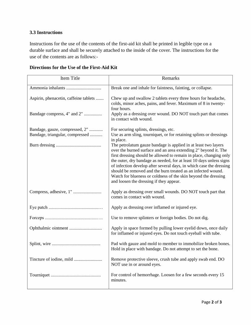
Page 2 of 3
3.3 Instructions
Instructions for the use of the contents of the first-aid kit shall be printed in legible type on a
durable surface and shall be securely attached to the inside of the cover. The instructions for the
use of the contents are as follows:-
Directions for the Use of the First-Aid Kit
Item Title Remarks
Ammonia inhalants ...............................
Aspirin, phenacetin, caffeine tablets .......
Bandage compress, 4" and 2" ................
Bandage, gauze, compressed, 2" ............
Bandage, triangular, compressed ...........
Burn dressing ........................................
Compress, adhesive, 1" .........................
Eye patch ............................................…
Forceps ..............................................….
Ophthalmic ointment .............................
Splint, wire ...........................................
Tincture of iodine, mild .........................
Tourniquet ............................................
Break one and inhale for faintness, fainting, or collapse.
Chew up and swallow 2 tablets every three hours for headache,
colds, minor aches, pains, and fever. Maximum of 8 in twenty-
four hours.
Apply as a dressing over wound. DO NOT touch part that comes
in contact with wound.
For securing splints, dressings, etc.
Use as arm sling, tourniquet, or for retaining splints or dressings
in place.
The petrolatum gauze bandage is applied in at least two layers
over the burned surface and an area extending 2" beyond it. The
first dressing should be allowed to remain in place, changing only
the outer, dry bandage as needed, for at least 10 days unless signs
of infection develop after several days, in which case the dressing
should be removed and the burn treated as an infected wound.
Watch for blueness or coldness of the skin beyond the dressing
and loosen the dressing if they appear.
Apply as dressing over small wounds. DO NOT touch part that
comes in contact with wound.
Apply as dressing over inflamed or injured eye.
Use to remove splinters or foreign bodies. Do not dig.
Apply in space formed by pulling lower eyelid down, once daily
for inflamed or injured eyes. Do not touch eyeball with tube.
Pad with gauze and mold to member to immobilize broken bones.
Hold in place with bandage. Do not attempt to set the bone.
Remove protective sleeve, crush tube and apply swab end. DO
NOT use in or around eyes.
For control of hemorrhage. Loosen for a few seconds every 15
minutes.

Page 3 of 3
4 Marking
Each approved first-aid kit shall be permanently marked with the following information: name of
manufacturer, trade name symbol, model number, or other identification used by the
manufacturer and the words “FIRST-AID KIT”.

Page 1 of 2
Annex 9 (SCV Code VII/10.3)
ESTIMATING GUIDELINES FOR HOLDING TANK CAPACITY
1 These calculations shall be used as guidelines, as capacities are not mandated. The capacity of
each Marine Sanitation Device (MSD) should be evaluated in terms of the vessel’s size, route,
service, and particular circumstances. These capacities consider only “black-water” toilet drains.
On the average, each person will produce 0.4 gallons of waste per day.
2 Flush Rate. Table A9-1 estimates the water used per flush by different toilet systems.
TABLE A9-1
APPROXIMATE FLUSH CAPACITIES FOR VESSEL TOILETS
DRAINING TO MARINE SANITATION DEVICES
System Type Gallons per flush
Conventional (flushometer)
Recirculating
Vacuum
Hand Pump
Electric Pump
5.0
0.1
0.3
0.5
1.0
3 Wastewater produced. Table A9-2 estimates the gallons of wastewater produced per person per
day, based on the plumbing type, and the way the boat operates.
TABLE A9-2
GALLONS OF WASTEWATER PER PERSON
PER DAY BASED ON PLUMBING TYPE
Trip Length User Conv. Recirc. Vacuum Band
Pump Electric
LONG
(Note 1)
MEDIUM
(Note 2)
SHORT
(Note 3)
Crew
Pax
Crew
Pax
Crew
Pax
25.4
25.4
25.4
8.3
12.7
6.35
0.5
0.5
0.5
0.17
0.25
0.25
1.9
1.9
1.9
1.9
0.95
0.5
2.9
2.9
2.9
1.0
1.95
0.7
5.4
5.4
5.4
1.8
2.7
1.35

Page 2 of 2
Note
1 Crew and passengers aboard 24 hour/day.
2 Crew aboard 24-hour/day; 2 groups of passengers aboard for 4 hours each (2 trips/day), each
passenger using facilities once.
3 All crew aboard 12 hour/day; 6 groups of passengers aboard for 2 hours (6 trips per day), one
fourth of passengers using facilities once.

Page 1 of 2
Annex 10 (SCV Code IX/3.1)
SPECIMEN OF BOATMASTER AND BOAT ENGINEER LICENCE
Certificate no:
BOATMASTER LICENCE GRADE 1/2/3 issued by the
Merchant Shipping Secretariat
under the provisions of the
Code of Safety for Small Commercial Vessels
This is to certify that ………………………………………………………………………………
is entitled to serve in a capacity requiring a Boatmaster Grade 1/2/3 in commercial vessels of
............................ metres in length operating in Protected/Coastal/Exposed waters.
The holder is further entitled to serve in such other vessels and in such areas as may be endorsed
on this certificate.
ENDORSEMENT:
Date of Issue: Date of Expiry:
------------------------- -----------------------------
Signature of Holder OFFICIAL STAMP Authorized Official
This Licence is valid only if the holder is in possession of a valid medical fitness certificate
Photograph

Page 2 of 2
SPECIMEN OF BOATMASTER AND BOAT ENGINEER LICENCE
Certificate no:
BOAT ENGINEER LICENCE GRADE 1/2/3 issued by the
Merchant Shipping Secretariat
under the provisions of the
Code of Safety for Small Commercial Vessels
This is to certify that ………………………………………………………………………………
is entitled to serve in a capacity requiring a Boat Engineer Grade 1/2 in commercial vessels with
an installed power of less than 750 kW operating in Coastal/ Exposed waters.
The holder is further entitled to serve in such other vessels and in such areas as may be endorsed
on this certificate.
ENDORSEMENT:
Date of Issue: Date of Expiry:
------------------------- -----------------------------
Signature of Holder OFFICIAL STAMP Authorized Official
This Licence is valid only if the holder is in possession of a valid medical fitness certificate
Photograph
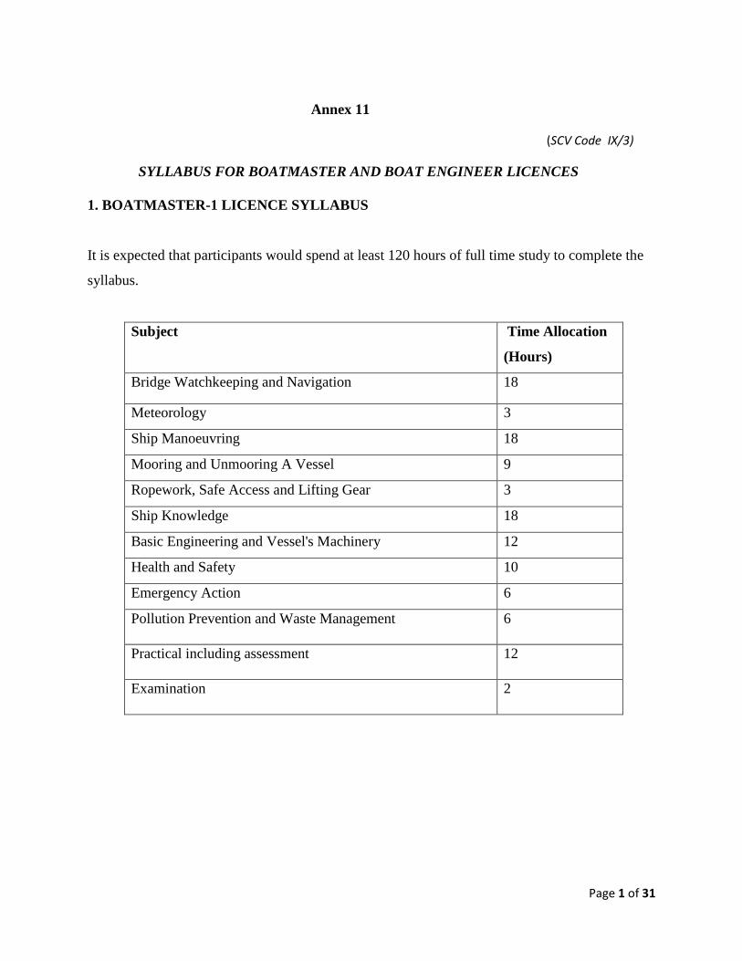
Page 1 of 31
Annex 11
(SCV Code IX/3)
SYLLABUS FOR BOATMASTER AND BOAT ENGINEER LICENCES
1. BOATMASTER-1 LICENCE SYLLABUS
It is expected that participants would spend at least 120 hours of full time study to complete the
syllabus.
Subject Time Allocation
(Hours)
Bridge Watchkeeping and Navigation 18
Meteorology 3
Ship Manoeuvring 18
Mooring and Unmooring A Vessel 9
Ropework, Safe Access and Lifting Gear 3
Ship Knowledge 18
Basic Engineering and Vessel's Machinery 12
Health and Safety 10
Emergency Action 6
Pollution Prevention and Waste Management 6
Practical including assessment 12
Examination 2
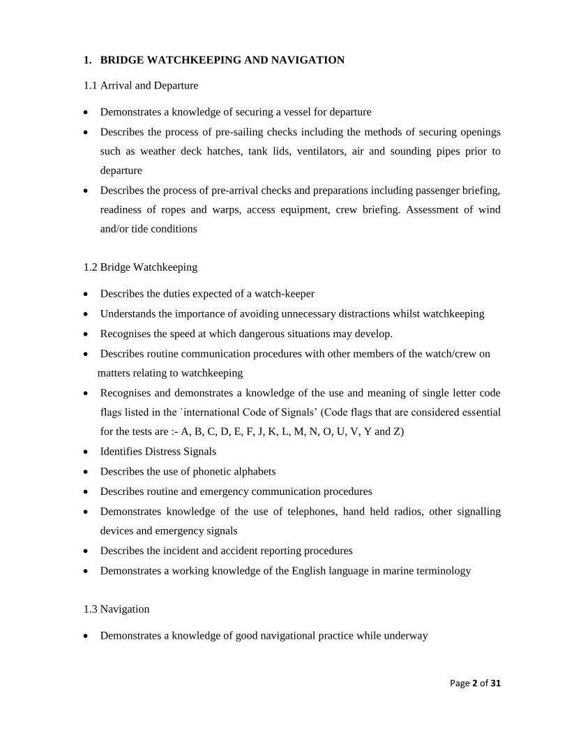
Page 2 of 31
1. BRIDGE WATCHKEEPING AND NAVIGATION
1.1 Arrival and Departure
Demonstrates a knowledge of securing a vessel for departure
Describes the process of pre-sailing checks including the methods of securing openings
such as weather deck hatches, tank lids, ventilators, air and sounding pipes prior to
departure
Describes the process of pre-arrival checks and preparations including passenger briefing,
readiness of ropes and warps, access equipment, crew briefing. Assessment of wind
and/or tide conditions
1.2 Bridge Watchkeeping
Describes the duties expected of a watch-keeper
Understands the importance of avoiding unnecessary distractions whilst watchkeeping
Recognises the speed at which dangerous situations may develop.
Describes routine communication procedures with other members of the watch/crew on
matters relating to watchkeeping
Recognises and demonstrates a knowledge of the use and meaning of single letter code
flags listed in the `international Code of Signals’ (Code flags that are considered essential
for the tests are :- A, B, C, D, E, F, J, K, L, M, N, O, U, V, Y and Z)
Identifies Distress Signals
Describes the use of phonetic alphabets
Describes routine and emergency communication procedures
Demonstrates knowledge of the use of telephones, hand held radios, other signalling
devices and emergency signals
Describes the incident and accident reporting procedures
Demonstrates a working knowledge of the English language in marine terminology
1.3 Navigation
Demonstrates a knowledge of good navigational practice while underway

Page 3 of 31
Demonstrates a knowledge of the content and application of the International Regulations
for Preventing Collisions at Sea
Describes IALA Buoyage System A and demonstrate a knowledge of the direction of
buoyage, recognition of marks from shape, colour, top- mark and light
Describes the procedure for taking the correct action for passing a cardinal mark
Demonstrates a knowledge of depth finding methods and equipment
Explains and describes the responsibilities of a lookout
Recognises the relative movement of other vessels
Use of VHF and VHF-DSC
1.4 Anchor Watch
Demonstrates knowledge of maintaining an anchor watch including checks made for
dragging an anchor
1.5 Tides and Currents
Demonstrates a knowledge of tide tables and tidal stream atlases
Knows the causes of spring and neap tides
Defines height of tide, Mean High Water Springs, Mean Low Water Springs, range of
tide, chart datum, height of charted objects, drying heights, spring and neap ranges
1.6 Compass Work
Demonstrates a knowledge of Magnetic Compass:
Demonstrates a knowledge of Gyro compass and repeaters, compass alarm and off
course alarm
Demonstrates the use of azimuth mirror, pelorus etc. for taking bearings
1.7 Chartwork
Demonstrates a knowledge of navigation charts
Describes the procedures for and makes necessary corrections to update charts and
publications including ECDIS.
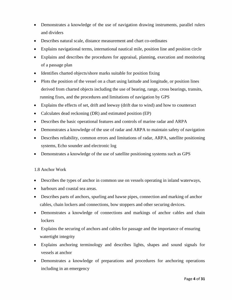
Page 4 of 31
Demonstrates a knowledge of the use of navigation drawing instruments, parallel rulers
and dividers
Describes natural scale, distance measurement and chart co-ordinates
Explains navigational terms, international nautical mile, position line and position circle
Explains and describes the procedures for appraisal, planning, execution and monitoring
of a passage plan
Identifies charted objects/shore marks suitable for position fixing
Plots the position of the vessel on a chart using latitude and longitude, or position lines
derived from charted objects including the use of bearing, range, cross bearings, transits,
running fixes, and the procedures and limitations of navigation by GPS
Explains the effects of set, drift and leeway (drift due to wind) and how to counteract
Calculates dead reckoning (DR) and estimated position (EP)
Describes the basic operational features and controls of marine radar and ARPA
Demonstrates a knowledge of the use of radar and ARPA to maintain safety of navigation
Describes reliability, common errors and limitations of radar, ARPA, satellite positioning
systems, Echo sounder and electronic log
Demonstrates a knowledge of the use of satellite positioning systems such as GPS
1.8 Anchor Work
Describes the types of anchor in common use on vessels operating in inland waterways,
harbours and coastal sea areas.
Describes parts of anchors, spurling and hawse pipes, connection and marking of anchor
cables, chain lockers and connections, bow stoppers and other securing devices.
Demonstrates a knowledge of connections and markings of anchor cables and chain
lockers
Explains the securing of anchors and cables for passage and the importance of ensuring
watertight integrity
Explains anchoring terminology and describes lights, shapes and sound signals for
vessels at anchor
Demonstrates a knowledge of preparations and procedures for anchoring operations
including in an emergency

Page 5 of 31
Describes the safety precautions when anchoring, securing anchors including the safe use
of machinery
2. METEOROLOGY
Describe Monsoon weather conditions
Explains meteorological terms in sufficient depth to interprets weather conditions
Describes types of cloud, cloud cover and precipitation
Defines visibility including horizontal visibility
Recognise and respond to extreme weather forecast and emerging conditions
Describes wind force, Beaufort scale, direction, true and apparent wind
Describes waves, sea and swell state
3. SHIP MANOEUVRING
3.1 Steering Systems & Their Function
• Describes the steering wheel or lever, helm indicators, steering motor, rudder, rudder
indicators and rate of turn indicators including functioning of the rudder and propeller
3.2 Steering by Compass
• Demonstrates a knowledge of course keeping, altering course by compass and the
procedure for making large alterations including maintaining of course by shore and lead
marks
• Explains the effect of weather, ship’s speed and condition of loading on steering
3.3 Ship Handling
• Explains the effects of single, twin, controllable pitch and fixed propellers on vessel
manoeuvring
• Describes the effects of wind, current and tidal stream on vessel manoeuvring/handling
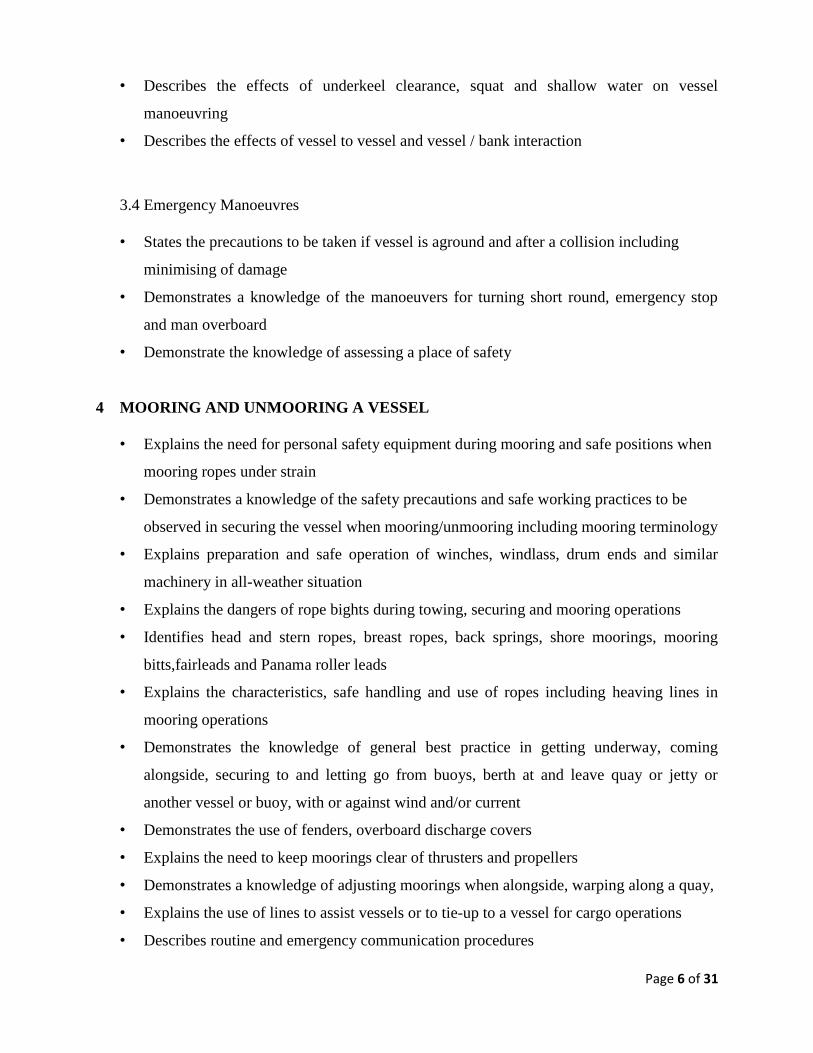
Page 6 of 31
• Describes the effects of underkeel clearance, squat and shallow water on vessel
manoeuvring
• Describes the effects of vessel to vessel and vessel / bank interaction
3.4 Emergency Manoeuvres
• States the precautions to be taken if vessel is aground and after a collision including
minimising of damage
• Demonstrates a knowledge of the manoeuvers for turning short round, emergency stop
and man overboard
• Demonstrate the knowledge of assessing a place of safety
4 MOORING AND UNMOORING A VESSEL
• Explains the need for personal safety equipment during mooring and safe positions when
mooring ropes under strain
• Demonstrates a knowledge of the safety precautions and safe working practices to be
observed in securing the vessel when mooring/unmooring including mooring terminology
• Explains preparation and safe operation of winches, windlass, drum ends and similar
machinery in all-weather situation
• Explains the dangers of rope bights during towing, securing and mooring operations
• Identifies head and stern ropes, breast ropes, back springs, shore moorings, mooring
bitts,fairleads and Panama roller leads
• Explains the characteristics, safe handling and use of ropes including heaving lines in
mooring operations
• Demonstrates the knowledge of general best practice in getting underway, coming
alongside, securing to and letting go from buoys, berth at and leave quay or jetty or
another vessel or buoy, with or against wind and/or current
• Demonstrates the use of fenders, overboard discharge covers
• Explains the need to keep moorings clear of thrusters and propellers
• Demonstrates a knowledge of adjusting moorings when alongside, warping along a quay,
• Explains the use of lines to assist vessels or to tie-up to a vessel for cargo operations
• Describes routine and emergency communication procedures

Page 7 of 31
5 ROPEWORK, SAFE ACCESS AND LIFTING GEAR
5.1 Ropework
• Demonstrates a knowledge of safe use of man-made fibre, wire and combination ropes
• Demonstrates the knowledge of inspection and certification of all wires and ropes
• Demonstrates a knowledge of correct use of knots, splices, bends, hitches and stoppers
• Demonstrate a knowledge of purchases, tackles and riggings including mechanical
advantage
5.2 Access
• Demonstrates a knowledge of the requirements to rig, recover and maintain gangways
and other safe means of access to a vessel
• Describes the methods available to ensure safe movement onboard ship
• Describes the effects of tide, wind, waves, swell, changes of draught, trim and passing
vessels while alongside
6 SHIP KNOWLEDGE
6.1 General
• Demonstrates a knowledge of terms and definitions used in connection with vessel
operations and vessel construction ( Operational area, Design category, Carrying
capacity-Cargo and Passengers)
• Demonstrates a knowledge of legislation, SCV Code and M Notices
• Demonstrates a knowledge of the law, codes, principles and procedures and other forms
of guidance relating to:
maintaining a safe working environment on board ship
safe movement to, from and around the vessel
reporting of accidents and dangerous occurrences

Page 8 of 31
risk assessment
using chemicals or other hazardous materials
personal protective clothing and equipment
Appreciates the requirements of records for commercial and legislative process
Describes the recording methods available – written records
Explains the requirement for accuracy, brevity and clarity in record keeping
6.2 Ship Construction
• Demonstrate a knowledge of ship construction features for various ship types sufficient to
assist with ensuring watertightness and sea worthiness including the function and
structure of tanks
• Describes securing of air and sounding pipes, bilge and ballast piping systems
from tanks/holds to engine rooms including non-return valves, sea chests and mud boxes
• Explains the causes of stress in a ship’s structure
• Describes the effect of pressure caused by the sea and by liquids in tanks (static and
moving), and stresses due to uneven loading on decks, holds and engine spaces
• Identifies structures to resist pounding, panting including the parts of structure liable to
sustain damage due to heavy weather, vibration, shifting cargo, grounding or collision
6.3 Ship Stability
• Describes the basic principles of ship stability including the principles of floatation
• Define mass, volume, density and relative density
• Define volume, displacement, deadweight, buoyancy, waterline length, breadth, draught,
• Length overall, Length between perpendicular, freeboard (freeboard deck/deck line to
waterline) and identifies hydrostatic data
• Define Centre of Buoyancy, Centre of Gravity, free surface, transverse metacentre,
righting lever, righting moment at small angle of heel
• Explain stable, neutral and unstable equilibrium, stiff and tender vessels
• Explain the effect on Centre of Gravity (G) on loading, discharging, moving weights,
ballasts or bunkers and changes (if any) in stability during voyage
• Explain the dangers and effect of free surface at small angle of heel
Page 9 of 31
6.4 Maintenance
• Identifies plans, specifications, materials and equipment and the need to ensure
availability
• Demonstrate a knowledge of use of various types of paints and correct lubrication of
moving parts including scheduling of lubrication for deck machinery and equipment
• Prepares surfaces for coating i.e. steel, aluminium and wood
• Explains the maintenance of fire-fighting and life-saving equipment
• Demonstrates a knowledge of the need for preparation of work area and resources for
maintenance
• Identifies work area, tools and materials including safe stowage and use of materials
6.5 Lifting Gear
• States the precaution to take when using lifting gear
• States that all cargo gear should be inspected before the start of operations each day
• Identifies lubrication schedules for deck machinery and equipment including correct
lubrication of moving parts
• Outlines the care and maintenance of lifting gear including derricks, cranes and other
gear
7 BASIC ENGINEERING AND VESSEL'S MACHINERY
7.1 General Engineering Practice and Procedures
• Demonstrates a knowledge of relevant safety regulations, machinery operating
instructions,conditions, manufacturer’s instructions
• Plans engineering practices and procedures for small vessel propulsion machinery,
auxiliaries and services in compliance with safety regulations including the use of
machinery schedules and instructions (to include manufacturer’s instructions).
• Explains system operation and principles involved including the appropriate sequence
and timing of activities for machinery and auxiliary operations
• Explains preparation of machinery and auxiliaries and knows how to carry out operations
according to plan

Page 10 of 31
• Describes how to locate common faults including the causes of machinery malfunctions
and actions required to be take
• Describes how to operate the control systems, possible problems and how to identify and
correct minor deviations
• Describes emergency shut-down sequence, timing and hazards
• Describes how to make adjustments to achieve and maintain safe operation including the
use of instruments to monitor conditions
• Describes measures to avoid pollution of the marine environment
7.2 Pumping and associated Control Systems
• Demonstrates a knowledge of relevant safety regulations, conditions, manufacturer’s
instructions and maintenance schedules with respect to pumping and associated control
systems
• Describes planning for pumping operations
• Describes routine pumping operations, bilge, ballast and operational pumping systems,
equipment and machinery operations and possible problems that could occur
• Describes how to use instruments to monitor conditions
• Demonstrates a knowledge of precautions to prevent pollution of the marine
environment,anti-pollution procedures and associated equipment
7.3 Electrical Equipment
Describes the basic principles and operation of electrical machines (to include alternators
or generators and control systems)
Describes electrical systems, protection arrangements, circuits and circuit breakers,
instruments to monitor conditions
Describes the maintenance of electrical supply within given conditions, possible
problems and irregularities that could occur
Explains fault detection system operation and isolating procedures including simple fault
diagnosis, location of common faults on plant and control systems and actions to prevent
damage

Page 11 of 31
8 HEALTH AND SAFETY
Demonstrates a knowledge of the principles of health and safety practice
Demonstrates a knowledge and understanding of regulations and guidance on risk
assessment and other general duties under Health and Safety
Demonstrates a knowledge of the safety precautions, regulations, codes of practice and
guidelines relating to:
working at a height or outboard
demonstrates knowledge of planned maintenance systems for LSA and FFA
entry into and working in enclosed spaces
use of powered cleaning devices, hand and powered tools
operating lifting plant and the slinging of heavy equipment
use and storage of chemical or other hazardous materials
protective equipment and clothing
cargo access equipment
maintenance of batteries
noise
vibration
9 EMERGENCY ACTION
• States the contingency plans and actions to take in the event of emergencies including
imminent collision, collision, grounding, beaching, flooding, man-overboard and
abandon ship and fire
• Identifies the nature of emergency and takes initial action to conform to the vessel’s
emergency procedure
• Communicates information to the relevant personnel promptly and accurately
• Takes appropriate action on recognising an alarm signal in accordance with emergency
procedure including the raising of alarm promptly by the most appropriate method
available
• Explains the methods of making distress and emergency alerts including use of
equipment
Page 12 of 31
• Describes how to avoid sending false alerts and the remedial action to take if a false alert
is sent
• Demonstrates a knowledge of Search and Rescue in Sri Lanka
10 POLLUTION PREVENTION AND WASTE MANAGEMENT
• Describes how MARPOL and other current guidance and legislation(MEPA regulations)
provides knowledge of
the precautions and procedures to be taken to prevent pollution of the marine
environment.
• Demonstrates a knowledge of policies regarding vessel operations, bunkering.
11. PRACTICAL
Berthing and unberthing
Coming to and weighing anchor
Making fast to and leaving a buoy
Boat manoeuvring in confined waters
Knowledge and effect of transverse thrust
Practical demonstration on the use of VHF-DSC,EPIRB,SART and SAT-C on board the
applicant’s vessel. The holder must have knowledge of procedures used in GMDSS
communications particularly with respect to distress, urgency, safety and navigational
messages and of the adverse effect of misuse of such equipment
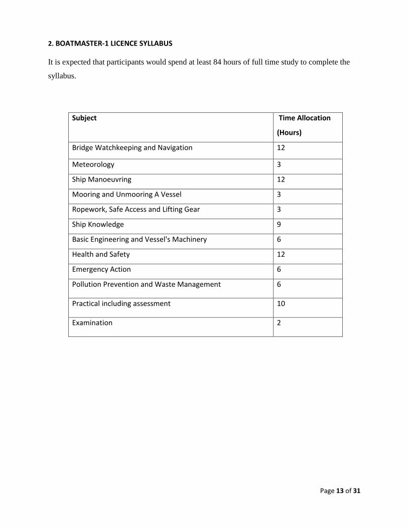
Page 13 of 31
2. BOATMASTER-1 LICENCE SYLLABUS
It is expected that participants would spend at least 84 hours of full time study to complete the
syllabus.
Subject Time Allocation
(Hours)
Bridge Watchkeeping and Navigation 12
Meteorology 3
Ship Manoeuvring 12
Mooring and Unmooring A Vessel 3
Ropework, Safe Access and Lifting Gear 3
Ship Knowledge 9
Basic Engineering and Vessel's Machinery 6
Health and Safety 12
Emergency Action 6
Pollution Prevention and Waste Management 6
Practical including assessment 10
Examination 2
Page 14 of 31
1. BRIDGE WATCHKEEPING AND NAVIGATION
1.1 Arrival and Departure
Demonstrates a knowledge of securing a vessel for departure
Describes the process of pre-sailing checks including the methods of securing openings
such as weather deck hatches, tank lids, ventilators, air and sounding pipes prior to
departure
Describes the process of pre-arrival checks and preparations including passenger briefing,
readiness of ropes and warps, access equipment, crew briefing. Assessment of wind
and/or tide conditions
1.2 Bridge Watchkeeping
Describes the duties expected of a watch-keeper
Recognises the speed at which dangerous situations may develop.
Recognises and demonstrates a knowledge of the use and meaning of single letter code
flags listed in the `international Code of Signals’ (Code flags that are considered essential
for the tests are :- A, B, C, D, E, F, J, K, L, M, N, O, U, V, Y and Z)
Identifies Distress Signals
Describes routine and emergency communication procedures
Demonstrates knowledge of the use of telephones, hand held radios, other signalling
devices and emergency signals
Describes the incident and accident reporting procedures
1.3 Navigation
Demonstrates a knowledge of the content and application of the International Regulations
for Preventing Collisions at Sea
Describes IALA Buoyage System A and demonstrate a knowledge of the direction of
buoyage, recognition of marks from shape, colour, top- mark and light
Describes the procedure for taking the correct action for passing a cardinal mark
Demonstrates a knowledge of depth finding methods and equipment
Recognises the relative movement of other vessels

Page 15 of 31
Use of VHF and VHF-DSC
1.4 Anchor Watch
Demonstrates knowledge of maintaining an anchor watch including checks made for
dragging an anchor
1.5 Tides and Currents
Demonstrates a knowledge of tide tables and tidal stream atlases
1.6 Compass Work
Demonstrates a knowledge of Magnetic Compass:
Demonstrates the use of azimuth mirror, pelorus etc. for taking bearings
1.7 Chartwork
Demonstrates a knowledge of navigation charts
Describes the procedures for and makes necessary corrections to update charts and
publications including ECDIS.
Explains the effects of set, drift and leeway (drift due to wind) and how to counteract
Describes the basic operational features and controls of marine radar and ARPA
Demonstrates a knowledge of the use of radar and ARPA to maintain safety of navigation
Describes reliability, common errors and limitations of radar, ARPA, satellite positioning
systems, Echo sounder and electronic log
Demonstrates a knowledge of the use of satellite positioning systems such as GPS
1.8 Anchor Work
Describes parts of anchors, spurling and hawse pipes, connection and marking of anchor
cables, chain lockers and connections, bow stoppers and other securing devices.
Demonstrates a knowledge of connections and markings of anchor cables and chain
lockers
Explains the securing of anchors and cables for passage and the importance of ensuring
Page 16 of 31
watertight integrity
Explains anchoring terminology and describes lights, shapes and sound signals for
vessels at anchor
Demonstrates a knowledge of preparations and procedures for anchoring operations
including in an emergency
Describes the safety precautions when anchoring, securing anchors including the safe use
of machinery
2 METEOROLOGY
Explains meteorological terms in sufficient depth to interprets weather conditions
Describes wind force, Beaufort scale, direction, true and apparent wind
Describes waves, sea and swell state
3 SHIP MANOEUVRING
3.1 Steering Systems & Their Function
• Demonstrates a knowledge of the components of steering systems and their function
including selection of information from instruction manual
• Describes the steering wheel or lever, helm indicators, steering motor, rudder, rudder
indicators and rate of turn indicators including functioning of the rudder and propeller
• Describes emergency steering systems including the change-over procedures
3.2. Steering by Compass
• Demonstrates a knowledge of steering a vessel including helm orders and altering course
by helm orders
• Demonstrates a knowledge of course keeping, altering course by compass and the
procedure for making large alterations including maintaining of course by shore and lead
marks
• Explains the effect of weather, ship’s speed and condition of loading on steering
Page 17 of 31
3.3Ship Handling
• Explains the effects of deadweight, draught, trim, speed, rudder angle and
propeller/transverse thrust on manoeuvring, turning circles and stopping distances
• Explains the effects of single, twin, controllable pitch and fixed propellers on vessel
manoeuvring
• Describes the effects of wind, current and tidal stream on vessel manoeuvring/handling
• Describes the effects of underkeel clearance, squat and shallow water on vessel
manoeuvring
• Describes the effects of vessel to vessel and vessel / bank interaction
3.4 Emergency Manoeuvres
• States the precautions to be taken if vessel is aground and after a collision including
minimising of damage
• Demonstrates a knowledge of the manoeuvers for turning short round, emergency stop
and man overboard
• Describes the precautions and procedures required to be carried out when heavy weather
is expected including the rigging of safety lines, restriction of access to the weather deck
• Demonstrate the knowledge of assessing a place of safety
• Demonstrates a knowledge of turning a vessel in rough sea
• Demonstrates a knowledge of hazards resulting from pitching, pounding, rolling, racing
and broaching to (turning sideways or having stern sea in surf)
• Describes how and when to make report on the conditions of seaworthiness
4 MOORING AND UNMOORING A VESSEL
• Demonstrates the knowledge of general best practice in getting underway, coming
alongside, securing to and letting go from buoys, berth at and leave quay or jetty or
another vessel or buoy, with or against wind and/or current
• Demonstrates the use of fenders, overboard discharge covers
• Describes routine and emergency communication procedures
Page 18 of 31
5 ROPEWORK, SAFE ACCESS AND LIFTING GEAR
5.4 Ropework
• Demonstrates a knowledge of safe use of man-made fibre, wire and combination ropes
• Demonstrates the knowledge of inspection and certification of all wires and ropes
5.5 Access
• Demonstrates a knowledge of the requirements to rig, recover and maintain gangways
and other safe means of access to a vessel
• Describes the effects of tide, wind, waves, swell, changes of draught, trim and passing
vessels while alongside
6 SHIP KNOWLEDGE
6.1 General
• Demonstrates a knowledge of terms and definitions used in connection with vessel
operations and vessel construction ( Operational area, Design category, Carrying
capacity-Cargo and Passengers)
• Demonstrates a knowledge of legislation, SCV Code and M Notices
• Demonstrates a knowledge of the law, codes, principles and procedures and other forms
of guidance relating to:
maintaining a safe working environment on board ship
safe movement to, from and around the vessel
reporting of accidents and dangerous occurrences
risk assessment
using chemicals or other hazardous materials
personal protective clothing and equipment
Describes the recording methods available – written records
Explains the requirement for accuracy, brevity and clarity in record keeping
6.2 Ship Construction
• Explains the causes of stress in a ship’s structure
• Describes the effect of pressure caused by the sea and by liquids in tanks (static and

Page 19 of 31
moving), and stresses due to uneven loading on decks, holds and engine spaces
6.3 Ship Stability
• Describes the basic principles of ship stability including the principles of floatation
• Explain the effect on Centre of Gravity (G) on loading, discharging, moving weights,
ballasts or bunkers and changes (if any) in stability during voyage
• Explain the dangers and effect of free surface at small angle of heel
6.4 Maintenance
• Identifies plans, specifications, materials and equipment and the need to ensure
availability
• Explains the maintenance of fire-fighting and life-saving equipment
6.5 Lifting Gear
• States the precaution to take when using lifting gear
7 BASIC ENGINEERING AND VESSEL'S MACHINERY
7.1 General Engineering Practice and Procedures
• Demonstrates a knowledge of relevant safety regulations, machinery operating
instructions,conditions, manufacturer’s instructions
• Describes emergency shut-down sequence, timing and hazards
• Describes how to make adjustments to achieve and maintain safe operation including the
use of instruments to monitor conditions
• Describes measures to avoid pollution of the marine environment
7.2 Pumping and associated Control Systems
• Describes planning for pumping operations
• Describes routine pumping operations, bilge, ballast and operational pumping systems,
equipment and machinery operations and possible problems that could occur

Page 20 of 31
7.3 Electrical Equipment
Describes the basic principles and operation of electrical machines (to include alternators
or generators and control systems)
8 HEALTH AND SAFETY
Demonstrates a knowledge of the principles of health and safety practice
Demonstrates a knowledge and understanding of regulations and guidance on risk
assessment and other general duties under Health and Safety
Demonstrates a knowledge of the safety precautions, regulations, codes of practice and
guidelines relating to:
working at a height or outboard
demonstrates knowledge of planned maintenance systems for LSA and FFA
entry into and working in enclosed spaces
use of powered cleaning devices, hand and powered tools
operating lifting plant and the slinging of heavy equipment
use and storage of chemical or other hazardous materials
protective equipment and clothing
cargo access equipment
maintenance of batteries
noise
vibration
9 EMERGENCY ACTION
• States the contingency plans and actions to take in the event of emergencies including
imminent collision, collision, grounding, beaching, flooding, man-overboard and
abandon ship and fire
• Identifies the nature of emergency and takes initial action to conform to the vessel’s
emergency procedure
• Communicates information to the relevant personnel promptly and accurately
• Takes appropriate action on recognising an alarm signal in accordance with emergency
Page 21 of 31
procedure including the raising of alarm promptly by the most appropriate method
available
• Explains the methods of making distress and emergency alerts including use of
equipment
• Describes how to avoid sending false alerts and the remedial action to take if a false alert
is sent
• Demonstrates a knowledge of Search and Rescue in Sri Lanka
10 POLLUTION PREVENTION AND WASTE MANAGEMENT
• Describes how MARPOL and other current guidance and legislation(MEPA regulations)
provides knowledge of
the precautions and procedures to be taken to prevent pollution of the marine
environment.
• Demonstrates a knowledge of policies regarding vessel operations, bunkering.
11. PRACTICAL
Berthing and unberthing
Coming to and weighing anchor
Making fast to and leaving a buoy
Boat manoeuvring in confined waters
Knowledge and effect of transverse thrust
Practical demonstration on the use of VHF-DSC,EPIRB, SART and SAT-C on board the
applicant’s vessel. The holder must have knowledge of procedures used in GMDSS
communications particularly with respect to distress, urgency, safety and navigational
messages and of the adverse effect of misuse of such equipment

Page 22 of 31
1.2 Additional Qualifications
.1 Basic Safety Training Courses
.1 Basic Sea Survival Technics - STCW code, table A-VI/1-1
.2 Elementary First Aid - STCW code, table A-VI/1-3
.3 Fire Prevention and Firefighting - STCW code, table A-VI/1-2
.4 Personal Safety and Social Responsibility - STCW code, table A-VI/1-4
2. BOAT ENGINEER SYLLABUS
a. Grade 1
2.1a Emergencies
The following are some of which the candidate must be knowledgeable.
.1 Assessment of damage and damage control
.2 Temporary plugging of leaks
.3 Man overboard procedure
.4 Fire in the engine compartment
.5 Action to be taken in the event of ingress of seawater into the engine compartment
.6 Procedure to be followed in the event of partial or total electrical failure
.7 Isolation of main engine units in the event of malfunction and the action necessary to continue
safe operation.
.8 Action to be taken when abandoning the vessel
2.2a Operating Procedure
The candidate should have knowledge in the following -
.1 Method of preparation of various systems and checks prior to starting which should include -
.1 Machinery
.2 Clutches
.3 Stern tube
.4 Propeller

Page 23 of 31
.5 Steering gear
.6 Sump level
.7 Filters
.8 Fuel system
.9 Safety equipment
.2 Checks during running to include
.1 Machinery
.2 Stern tube
.3 Steering gear
.4 Sump levels
.5 Filters
.3 Methods of fault detection, correction and emergency repairs
.4 Precautions to ensure that machinery is not damaged due to misuse through overspeeding
overloading, lack of lubrication or by corrosion.
2.3a Prevention of Marine Pollution:
The candidate should have knowledge of the following:
.1 Regulations applicable to the prevention of pollution (a general appreciation.
.2 Factors contributing to and precautions to be observed to prevent marine pollution when
pumping out bilges and particularly, when changing lubricating oil
.3 that disposal into the sea of all plastics, including but not limited to synthetic ropes, plastic
sheeting and garbage bags etc., is prohibited
2.4a Marine Engines
The candidate should have a thorough knowledge in the following areas
.1 Working principles of marine engines
.1 Two stroke and four stroke cycles
.2 Piston position, valve positions, timing etc.
.2 Comparison between diesel and petrol engines
.1 Engine capacity
.2 Bore
.3 Difference between compression and electric spark ignition

Page 24 of 31
.4 Fuel injection systems
.5 The weight of the engine block
.3 Air and exhaust systems
.1 Air fitters, manifolds, exhaust pipes and silences
.2 Use of pumps and blowers
.3 Supercharging and its effects on the engine
.4 Fuel systems
.1 Types of fuel
.2 Storage and transfer systems
.3 Effects of dirt and water contamination
.4 Fitters, separators, pumps, carburetors and fuel injection systems.
.5 The combustion and ignition process
.5 Cooling systems
.1 Mediums of cooling
.2 Heat exchanges
.3 Radiators
.4 Control of overheating
.5 Advantages and disadvantages of various cooling systems
.6 Corrosion and use of sacrificial anodes
.6 Lubrication Systems
.1 Principles and purposes of lubrication
.2 Types of bearings and their fitting, care, maintenance and adjustment
.3 Types and grading of lubricating oils
.4 Use of grease
.5 Sea water contamination and procedures after contamination
.7 Starting Systems
.1 Hand recoil
.2 Electric
.3 Compressed air
2.5a Electrical Systems
Page 25 of 31
The candidate should have knowledge of the following areas
.1 General construction, care and maintenance of alternating and direct current generators
.2 Switch boards and shipboard circuitry
.3 Starters and their care and maintenance
.4 Batteries and their care and maintenance
.5 Operating precautions and dangers of explosion short circuits etc.
2.6a Pumps and Pumping Systems
The candidate should have knowledge of the following areas
.1 Construction, care and maintenance of all types of pumps used on vessels
.2 Causes of loss of output, methods of priming and maintenance of priming devices
.3 Arrangement of bilge water pumping systems
.4 Types of valve chests
.5 Causes of deterioration and leakage and its temporary and permanent repairs
.6 Procedure for getting rid of oily bilgewater.
2.7a Propulsion Systems
The candidate should have knowledge of the following
.1 Stern tube
.1 Stern tube bearings
.2 Stern glands and packing
.2 Clutches and gear boxes
.3 Shafting
.1 Intermediate shafts
.2 Types of bearings
.3 Types of shafts
.4 Shaft alignment checking and correction of misalignment.
.4 Damage to and repair of propellers
.5 Typical steering gear arrangement including mechanical, hydraulic and electro hydraulic,
emergency procedures, care and maintenance.
Page 26 of 31
2.8a Safe - Working Procedures
The candidate should have knowledge of the following -
.1 The use of instruction manuals which should be understood and clearly followed for both the
operation and maintenance of the machinery.
.2 The effective use of safety guards in way of all hot parts and moving parts for the safety of
personnel.
.3 Safety and shut off devices associated with fuel oil and lubricating oil systems.
.4 The use of adequate protective equipment and clothing.
.5 Safe use and care of all tools
.6 Safe use of all lifting devices
.7 Display of warning signs.
2.9a Auxiliary Machinery and Systems
The candidate should have knowledge in the following -
.1 Air Compressors
The general arrangement of single and multi-stage compressors, their care maintenance and
emergency repairs.
.2 Hydraulic Systems
Basic principles of power hydraulics, hydraulic fluid systems for winches, steering gear etc, fault
finding care and maintenance.
.3 Electro technology
.1 General principles of electricity - voltage, current, resistance
.2 Basic principles of alternating and direct current
.3 Effects of electric current; conductors and insulators; lamps; cable and fuses.
.4 The construction, capacity, care and maintenance of batteries.
.4 Deck Machinery
Winches and windlass, types, method of operation and maintenance.
2.10a Outboard Engines
The candidate should have knowledge of the following -

Page 27 of 31
.1 Principles of two and four stroke engines and related valve and crank position.
.2 The purpose and working of -
.1 Flywheel
.2 Valves and scavenging
.3 Fuel system
.4 Ignition system
.5 Transmission
.6 Gear box
.7 Lubrication
.8 Cooling
.9 Starting
.3 Trouble identification
.1 Starting difficulties
.2 Running difficulties
.3 Importance of replacement shear pins
.4 Servicing and Maintenance
.1 Inspection procedures
.2 Carburetor maintenance
.3 Engine mounting
.4 Procedures for lay up or storage.
b. Grade 2
2.1b Emergencies
The following are some of which the candidate must be knowledgeable.
.1 Assessment of damage and damage control
.2 Temporary plugging of leaks
.3 Man overboard procedure
.4 Fire in the engine compartment
.5 Action to be taken in the event of ingress of seawater into the engine compartment
.6 Procedure to be followed in the event of partial or total electrical failure
.7 Isolation of main engine units in the event of malfunction and the action necessary to continue
safe operation.
Page 28 of 31
.8 Action to be taken when abandoning the vessel
2.2b Operating Procedure
The candidate should have knowledge in the following -
.1 Method of preparation of various systems and checks prior to starting which should include -
.1 Machinery
.2 Clutches
.3 Propeller
.4 Sump level
.5 Filters
.6 Fuel system
.7 Safety equipment
.2 Checks during running to include
.1 Machinery
.2 Sump levels
.3 Filters
.3 Methods of fault detection, correction and emergency repairs
.4 Precautions to ensure that machinery is not damaged due to misuse through overspeeding
overloading, lack of lubrication or by corrosion.
2.3b Prevention of Marine Pollution:
The candidate should have knowledge of the following:
.1 Regulations applicable to the prevention of pollution (a general appreciation.
.2 Factors contributing to and precautions to be observed to prevent marine pollution when
pumping out bilges and particularly, when changing lubricating oil
.3 that disposal into the sea of all plastics, including but not limited to synthetic ropes, plastic
sheeting and garbage bags etc., is prohibited
2.4b Marine Engines
The candidate should have a thorough knowledge in the following areas

Page 29 of 31
.1 Working principles of marine engines
.1 Four stroke cycles
.2 Piston position, valve positions, timing etc.
.2 Comparison between diesel and petrol engines
.1 Engine capacity
.2 Bore
.3 Difference between compression and electric spark ignition
.4 Fuel injection systems
.3 Air and exhaust systems
.1 Air fitters, manifolds, exhaust pipes and silences
.4 Fuel systems
.1 Types of fuel
.2 Effects of dirt and water contamination
.3 The combustion and ignition process
.5 Cooling systems
.1 Mediums of cooling
.2 Radiators
.3 Control of overheating
.4 Corrosion and use of sacrificial anodes
.6 Lubrication Systems
.1 Principles and purposes of lubrication
.2 Types of bearings and their fitting, care, maintenance and adjustment
.3 Types and grading of lubricating oils
.4 Use of grease
.5 Sea water contamination and procedures after contamination
.7 Starting Systems
.1 Hand recoil
.2 Electric
2.5b Electrical Systems

Page 30 of 31
The candidate should have knowledge of the following areas
.1 Batteries and their care and maintenance
.2 Operating precautions and dangers of explosion short circuits etc.
2.6b Pumps and Pumping Systems
The candidate should have knowledge of the following areas
.1 Arrangement of bilge water pumping systems
.2 Causes of deterioration and leakage and its temporary and permanent repairs
.3 Procedure for getting rid of oily bilgewater.
2.7b Propulsion Systems
The candidate should have knowledge of the following
.1 Stern tube
.1 Stern glands and packing
.2 Clutches and gear boxes
.3 Shafting
.5 Typical steering gear arrangement including mechanical and hydraulic, emergency
procedures, care and maintenance.
2.8b Safe - Working Procedures
The candidate should have knowledge of the following -
.1 The use of instruction manuals which should be understood and clearly followed for both the
operation and maintenance of the machinery.
.2 The effective use of safety guards in way of all hot parts and moving parts for the safety of
personnel.
.3 Safety and shut off devices associated with fuel oil and lubricating oil systems.
.4 The use of adequate protective equipment and clothing.
.5 Safe use and care of all tools
.6 Display of warning signs.
2.9b Outboard Engines

Page 31 of 31
The candidate should have knowledge of the following -
.1 Principles of two and four stroke engines and related valve and crank position.
.2 The purpose and working of -
.1 Flywheel
.2 Valves and scavenging
.3 Fuel system
.4 Ignition system
.5 Transmission
.6 Gear box
.7 Lubrication
.8 Cooling
.9 Starting
.3 Trouble identification
.1 Starting difficulties
.2 Running difficulties
.3 Importance of replacement shear pins
.4 Servicing and Maintenance
.1 Inspection procedures
.2 Carburetor maintenance
.3 Engine mounting
.4 Procedures for lay up or storage.
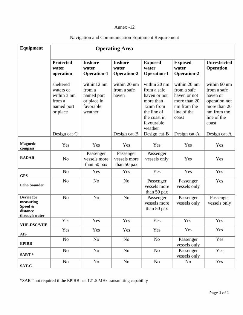
Page 1 of 1
Annex -12
Navigation and Communication Equipment Requirement
Equipment
Operating Area
Protected
water
operation
sheltered
waters or
within 3 nm
from a
named port
or place
Design cat-C
Inshore
water
Operation-1
within12 nm
from a
named port
or place in
favorable
weather
Inshore
water
Operation-2
within 20 nm
from a safe
haven
Design cat-B
Exposed
water
Operation-1
within 20 nm
from a safe
haven or not
more than
12nm from
the line of
the coast in
favourable
weather
Design cat-B
Exposed
water
Operation-2
within 20 nm
from a safe
haven or not
more than 20
nm from the
line of the
coast
Design cat-A
Unrestricted
Operation
within 60 nm
from a safe
haven or
operation not
more than 20
nm from the
line of the
coast
Design cat-A
Magnetic
compass
Yes
Yes
Yes
Yes
Yes
Yes
RADAR
No
Passenger
vessels more
than 50 pax
Passenger
vessels more
than 50 pax
Passenger
vessels only
Yes
Yes
GPS No Yes Yes Yes Yes Yes
Echo Sounder No No No Passenger
vessels more
than 50 pax
Passenger
vessels only
Yes
Device for
measuring
Speed &
distance
through water
No No No Passenger
vessels more
than 50 pax
Passenger
vessels only
Passenger
vessels only
VHF-DSC/VHF Yes Yes Yes Yes Yes Yes
AIS Yes Yes Yes Yes Yes Yes
EPIRB No No No No Passenger
vessels only
Yes
SART * No No No No Passenger
vessels only Yes
SAT-C No No No No No Yes
*SART not required if the EPIRB has 121.5 MHz transmitting capability
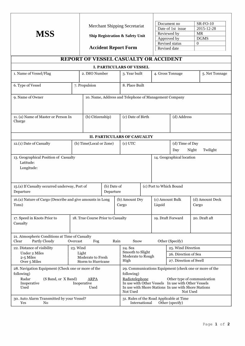
Page 1 of 2
MSS
Merchant Shipping Secretariat
Ship Registration & Safety Unit
Accident Report Form
Document no SR-FO-10
Date of 1st issue 2015-12-28
Reviewed by MR
Approved by DGMS
Revised status 0
Revised date
REPORT OF VESSEL CASUALTY OR ACCIDENT
I. PARTICULARS OF VESSEL 1. Name of Vessel/Flag
2. IMO Number
3. Year built
4. Gross Tonnage
5. Net Tonnage
6. Type of Vessel
7. Propulsion
8. Place Built
9. Name of Owner
10. Name, Address and Telephone of Management Company
11. (a) Name of Master or Person In Charge
(b) Citizenship)
(c) Date of Birth
(d) Address
II. PARTICULARS OF CASUALTY
12.(1) Date of Casualty
(b) Time(Local or Zone)
(c) UTC
(d) Time of Day
Day Night Twilight 13. Geographical Position of Casualty
Latitude:
Longitude:
14. Geographical location
15.(a) If Casualty occurred underway, Port of
Departure
(b) Date of
Departure
(c) Port to Which Bound
16.(a) Nature of Cargo (Describe and give amounts in Long
Tons)
(b) Amount Dry
Cargo
(c) Amount Bulk
Liquid
(d) Amount Deck
Cargo
17. Speed in Knots Prior to
Casualty
18. True Course Prior to Casualty
19. Draft Forward
20. Draft aft
21. Atmospheric Conditions at Time of Casualty
Clear Partly Cloudy Overcast Fog Rain Snow Other (Specify) 22. Distance of visibility
Under 2 Miles 2-5 Miles Over 5 Miles
23. Wind
Light Moderate to Fresh Storm to Hurricane
24. Sea Smooth to Slight Moderate to Rough High
25. Wind Direction 26. Direction of Sea 27. Direction of Swell
28. Navigation Equipment (Check one or more of the
following)
Radar (S Band, or X Band) ARPA Inoperative Inoperative Used Used
29. Communications Equipment (check one or more of the
following)
Radiotelephone Other type of communication In use with Other Vessels In use with Other Vessels In use with Shore Stations In use with Shore Stations Not Used Not Used
30. Auto Alarm Transmitted by your Vessel?
Yes No
31. Rules of the Road Applicable at Time
International Other (specify)

Page 2 of 2
MSS
Merchant Shipping Secretariat
Ship Registration & Safety Unit
Accident Report Form
Document no SR-FO-10
Date of 1st issue 2015-12-28
Reviewed by MR
Approved by DGMS
Revised status 0
Revised date
33.DESCRIPTION OF CASUALTY (Events and circumstances leading to casualty and present when it occurred. Attach diagram and additional sheets, if necessary.)
34.Number of Personnel Crew
Passengers
Other
Totals
35. Estimated Property Losses
(a) On Board
(a) To vessel
(b) Dead
(b) To cargo
(c) Missing
(c) To other property
(d) Injured
35. Is Vessel a Total Loss? Yes No
37. Remarks (Indicate assistance rendered by shore stations and vessels; recommendations for corrective safety measures. Attach additional sheets, if necessary.
38. Deck Officer on Duty at Time of Casualty
39. Engineer on Duty at Time of Casualty
Name
Name
Capacity
License No.
Capacity
License No.
40.Date of Report
41. Submitted by (Print name)
42. Signature
43. Title
INCIDENT TYPE (INITIAL CASUALTY EVENT)
A Collision Striking another ship (regardless of whether under way, anchored, moored)
B Stranding / Grounding Being aground or touching shore or sea bottom or underwater objects (wrecks) C Contact Striking any fixed or floating object other than those included in Collision D Fire or Explosion E Hull Failure / Failure of
WTD Not caused by any of the above
F Machinery Damage Which necessitated towage or shore assistance G Damages to Ship or
Equipment Not caused by any of the above
H Capsizing / Listing Not caused by any of the above I Missing: Assumed Lost J Labour
K Other Any other NOT covered by any of the above

Page 1 of 2
MSS Merchant Shipping Secretariat
Ship Registration & Safety Unit
Accident Report Form
Document no SR-FO-11
Date of 1st issue 2015-12-28
Reviewed by MR
Approved by DGMS
Revised status 0
Revised date
REPORT OF PERSONAL INJURY OR LOSS OF LIFE
I. PARTICULARS OF VESSEL 1. Name of Vessel
2. IMO Number 3. Name, Address and Telephone, Telefax of Management
Company
4 Type of Vessel
5 Propulsion
6. Name and address of Owner
II. PARTICULARS OF PERSON INJURED, DECEASED OR MISSING (Believed dead)
7. (a) Name of Person (b) Home Address (c) Date of Birth
(d) Citizenship
8. Seaman´s Book or Passport No
9. Status or Capacity on Vessel
10. Activity Engaged in at Time of Casualty 11. If Crew Member or Shore Worker
On Watch Working Other
12. (a) Name of Immediate Supervisor at Time of Casualty (b) Supervisor´s capacity or Status on Vessel
III. PARTICULARS OF CASUALTY OR ACCIDENT
13. (a) Date of Casualty
(b) Time (Local or Zone)
(c) UTC
(d) Time of Day Day Night Twilight
14. Geographical Location of Vessel at time of Casualty
15. (a) If Casualty occurred underway, Port of Departure
(b) Date of Departure (c) Port to Which Bound
16. (a) RESULT OF CASUALTY:
Injury Death Missing (Complete INJURY or DEATH entries below, as appropriate)
(b) Nature of Injury
(c) Total Days Incapacitated
(d) Reason for Death (e) Location of Individual at Death
(f) Date of Death

Page 2 of 2
MSS Merchant Shipping Secretariat
Ship Registration & Safety Unit
Accident Report Form
Document no SR-FO-11
Date of 1st issue 2015-12-28
Reviewed by MR
Approved by DGMS
Revised status 0
Revised date
DESCRIPTION OF CASUALTY (Give events leading up to casualty and how it occurred. Attach diagram and additional sheets, if necessary).
19. WITNESSES TO ACCIDENT (At least two, if possible)
Name Name
Address Address
Name Name
Address Address
IV. ASSISTANCE AND RECOMMENDATIONS
20. (a) MEDICO (Medical) MESSAGE SENT
(b) IF YES, GIVE DATE OF FIRST MESSAGE
(c) IF YES, GIVE TIME OF FIRST MESSAGE (Local or zone and description)
21. (a) TREATMENT ADMINISTERED
Yes No
(b) IF YES, BY WHOM
Ship´s Doctor Other Ships´ Personnel Other (Specify)
22. BRIEFLY DESCRIBE TREATMENT (If administered by other than M.D)
23. (a) Name of Hospital, If Person was Hospitalized (b) Address of Hospital
24. Recommendations for Corrective Safety Measures Pertinent to this Casualty
25. Date of Report
26. Submitted by (Print Name)
27. Signature 28. Title
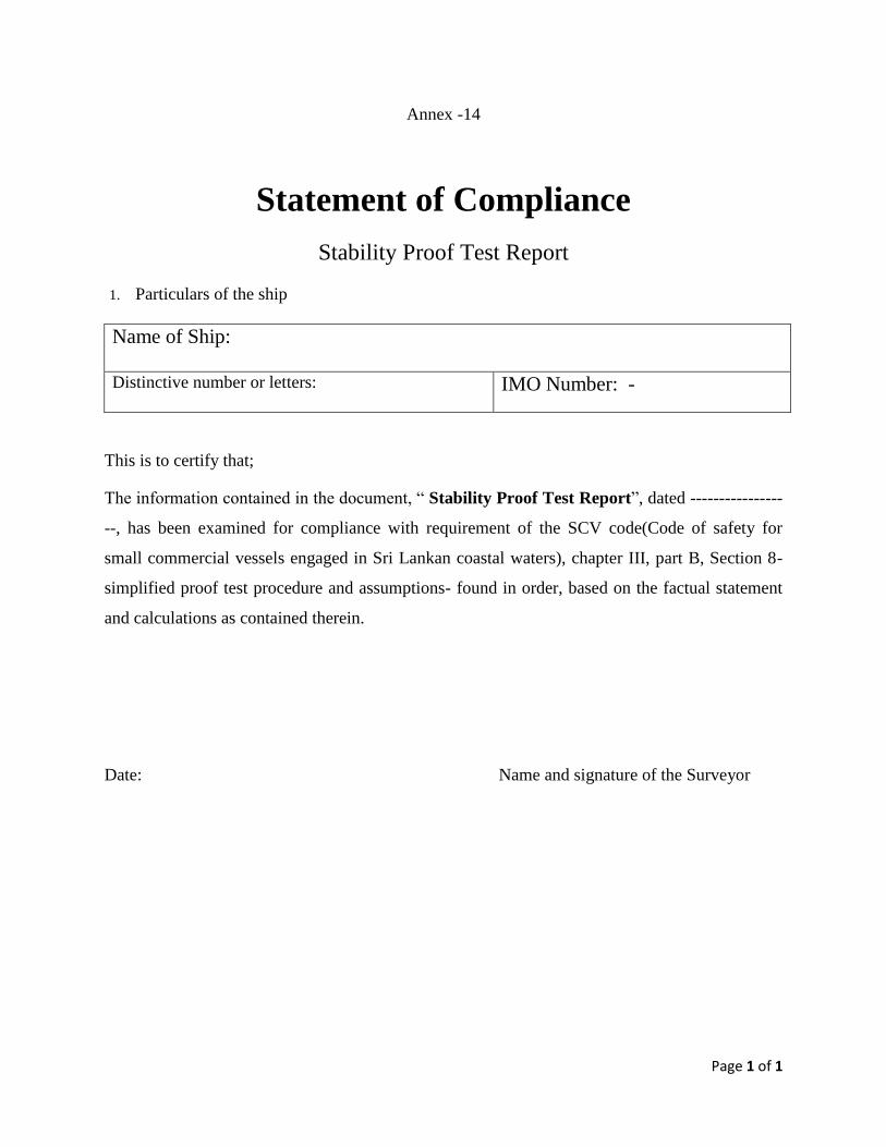
Page 1 of 1
Annex -14
Statement of Compliance
Stability Proof Test Report
1. Particulars of the ship
Name of Ship:
Distinctive number or letters:
IMO Number: -
This is to certify that;
The information contained in the document, “ Stability Proof Test Report”, dated ----------------
--, has been examined for compliance with requirement of the SCV code(Code of safety for
small commercial vessels engaged in Sri Lankan coastal waters), chapter III, part B, Section 8-
simplified proof test procedure and assumptions- found in order, based on the factual statement
and calculations as contained therein.
Date: Name and signature of the Surveyor
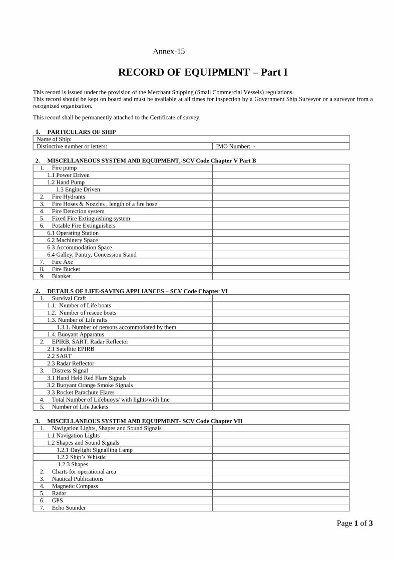
Page 1 of 3
nnex-15
RECORD OF EQUIPMENT – Part I This record is issued under the provision of the Merchant Shipping (Small Commercial Vessels) regulations.
This record should be kept on board and must be available at all times for inspection by a Government Ship Surveyor or a surveyor from a
recognized organization.
This record shall be permanently attached to the Certificate of survey.
1. PARTICULARS OF SHIP
Name of Ship:
Distinctive number or letters: IMO Number: -
2. MISCELLANEOUS SYSTEM AND EQUIPMENT,-SCV Code Chapter V Part B
1. Fire pump
1.1 Power Driven
1.2 Hand Pump
1.3 Engine Driven
2. Fire Hydrants
3. Fire Hoses & Nozzles , length of a fire hose
4. Fire Detection system
5. Fixed Fire Extinguishing system
6. Potable Fire Extinguishers
6.1 Operating Station
6.2 Machinery Space
6.3 Accommodation Space
6.4 Galley, Pantry, Concession Stand
7. Fire Axe
8. Fire Bucket
9. Blanket
2. DETAILS OF LIFE-SAVING APPLIANCES – SCV Code Chapter VI
1. Survival Craft
1.1. Number of Life boats
1.2. Number of rescue boats
1.3. Number of Life rafts
1.3.1. Number of persons accommodated by them
1.4. Buoyant Apparatus
2. EPIRB, SART, Radar Reflector
2.1 Satellite EPIRB
2.2 SART
2.3 Radar Reflector
3. Distress Signal
3.1 Hand Held Red Flare Signals
3.2 Buoyant Orange Smoke Signals
3.3 Rocket Parachute Flares
4. Total Number of Lifebuoys/ with lights/with line
5. Number of Life Jackets
3. MISCELLANEOUS SYSTEM AND EQUIPMENT- SCV Code Chapter VII
1. Navigation Lights, Shapes and Sound Signals
1.1 Navigation Lights
1.2 Shapes and Sound Signals
1.2.1 Daylight Signalling Lamp
1.2.2 Ship’s Whistle
1.2.3 Shapes
2. Charts for operational area
3. Nautical Publications
4. Magnetic Compass
5. Radar
6. GPS
7. Echo Sounder
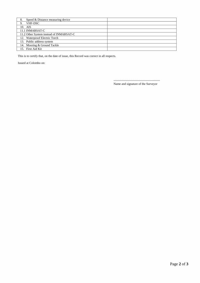
Page 2 of 3
8. Speed & Distance measuring device
9. VHF-DSC
10. AIS
11.1 INMARSAT-C
11.2 Other System instead of INMARSAT-C
12. Waterproof Electric Torch
13. Public address system
14. Mooring & Ground Tackle
15. First Aid Kit
This is to certify that, on the date of issue, this Record was correct in all respects.
Issued at Colombo on:
----------------------------------------------
Name and signature of the Surveyor
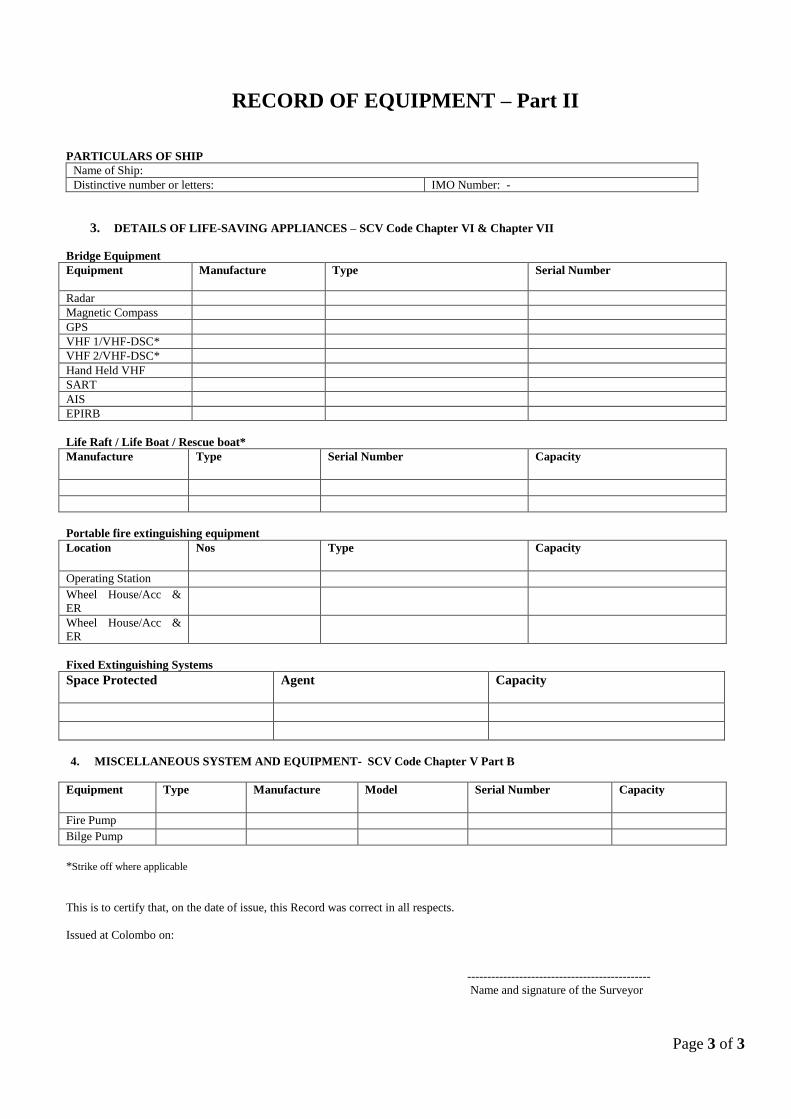
Page 3 of 3
RECORD OF EQUIPMENT – Part II
PARTICULARS OF SHIP
Name of Ship:
Distinctive number or letters: IMO Number: -
3. DETAILS OF LIFE-SAVING APPLIANCES – SCV Code Chapter VI & Chapter VII
Bridge Equipment
Equipment
Manufacture Type Serial Number
Radar
Magnetic Compass
GPS
VHF 1/VHF-DSC*
VHF 2/VHF-DSC*
Hand Held VHF
SART
AIS
EPIRB
Life Raft / Life Boat / Rescue boat*
Manufacture
Type Serial Number Capacity
Portable fire extinguishing equipment
Location
Nos Type Capacity
Operating Station
Wheel House/Acc &
ER
Wheel House/Acc &
ER
Fixed Extinguishing Systems
Space Protected
Agent Capacity
4. MISCELLANEOUS SYSTEM AND EQUIPMENT- SCV Code Chapter V Part B
Equipment Type Manufacture
Model Serial Number Capacity
Fire Pump
Bilge Pump
*Strike off where applicable
This is to certify that, on the date of issue, this Record was correct in all respects.
Issued at Colombo on:
----------------------------------------------
Name and signature of the Surveyor