section 9 pumping systems
TRANSCRIPT

SECTION 9: Pumping Systems .................................................................................................................................9-1
.............................................................................................................9-1Pumping in Gravity Systems .............................................................................................................................. 9-1Pumping in Pressure Systems ............................................................................................................................. 9-3
........................................................................................9-4Sump Basket .......................................................................................................................................................... 9-4Specifications ........................................................................................................................................................ 9-5Pump Tank ............................................................................................................................................................ 9-6Dosing Regimens: Demand vs. Timed .............................................................................................................. 9-8
...................................................................................................................................9-11Rule Requirements ............................................................................................................................................. 9-11Dual Pumps ....................................................................................................................................................... 9-15
..................................................................................................9-17Selecting Pumps ................................................................................................................................................ 9-17Fittings as Equivalent Straight Pipe ................................................................................................................ 9-19Sizing the Pump Tank ........................................................................................................................................ 9-20Float and Timer Setting ..................................................................................................................................... 9-22
..........................................................................................9-23Pump Tank .......................................................................................................................................................... 9-23Pump Discharge Assembly .............................................................................................................................. 9-24Sensors ................................................................................................................................................................. 9-25Controls ............................................................................................................................................................... 9-25Pump and Alarm ................................................................................................................................................ 9-26
.......................................................................9-31

SECTION 9: ■ 9-1
PUMPING SYSTEMS Pumps are used to move either raw sewage or septic tank effluent to different parts of the onsite sewage treatment system. Whether the pump handles raw sewage or septic tank effluent, a pumping system consists of four parts: 1) a pump tank or sump; 2) the discharge assembly; 3) the controls; and 4) the pump. How the sewage is expected to move through the system will determine where the pump is located, and the location of the pump often impacts the sizing and appearance of the four components. In one scenario, the pump is expected to deliver raw sewage to the pretreatment device, usu-ally a septic tank. In another scenario, septic tank effluent is moved to an additional pretreatment device, such as a sand filter or to the final soil dispersal and treatment site. In certain situations, more than one pump may be required.
Figure 9.1 shows two different gravity pumping situations. The upper figure shows the raw sewage flowing by gravity to a deep (≥4’ cover depth) septic tank and from there by gravity to a pump tank. The pump is then used to lift the septic tank effluent to the final
soil treatment area where it is distributed by gravity or pressure. In the event of pump fail-ure, water use would need to be restricted until the pump could be repaired or replaced. The amount of storage (reserve capacity) available is determined by the volume in the pump tank above the high alarm level. The lower part of Figure 9.1 shows a pump located in the basement that delivers waste-water generated in the basement to the house sewer, from which point the wastes flow by gravity into the septic tank. Many times this is referred to as a sump basket that holds the pump. However, the pump cannot be a sump pump because it will be handling sewage. If there is a basement toilet, a sewage ejector or solids handling pump would be used to lift the sewage to the house sewer. If there is a pump in the basement, a compartmented tank or
two tanks in series should be installed to provide septic tank capacity for adequate sol-ids separation. Even though only a portion of the sewage wastes are pumped, there will still be considerable turbulence in the first septic tank when the pump operates. In the event of pump failure, only the basement plumbing could not be used.
FIGURE 9.1
© 2020 Regents of the University of Minnesota. All rights reserved.
9-2 ■ SECTION 9:
FIGURE 9.2
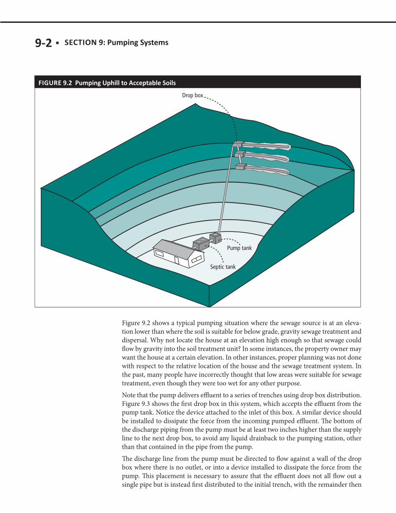
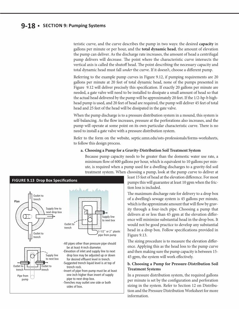
Figure 9.2 shows a typical pumping situation where the sewage source is at an eleva-tion lower than where the soil is suitable for below grade, gravity sewage treatment and dispersal. Why not locate the house at an elevation high enough so that sewage could flow by gravity into the soil treatment unit? In some instances, the property owner may want the house at a certain elevation. In other instances, proper planning was not done with respect to the relative location of the house and the sewage treatment system. In the past, many people have incorrectly thought that low areas were suitable for sewage treatment, even though they were too wet for any other purpose.Note that the pump delivers effluent to a series of trenches using drop box distribution. Figure 9.3 shows the first drop box in this system, which accepts the effluent from the pump tank. Notice the device attached to the inlet of this box. A similar device should be installed to dissipate the force from the incoming pumped effluent. The bottom of the discharge piping from the pump must be at least two inches higher than the supply line to the next drop box, to avoid any liquid drainback to the pumping station, other than that contained in the pipe from the pump. The discharge line from the pump must be directed to flow against a wall of the drop box where there is no outlet, or into a device installed to dissipate the force from the pump. This placement is necessary to assure that the effluent does not all flow out a single pipe but is instead first distributed to the initial trench, with the remainder then

SECTION 9: ■ 9-3
flowing through the supply line to the next drop box. Subsequent drop boxes in the system in Figure 9.2 will be similar to the one shown in Figure 9.4. The pump capacity for these applications should be between 15-45 gpm. Using the pump curve and rise in elevation can allow for proper selection.
FIGURE 9.3
FIGURE 9.4
There exists a third situation in which the pump is used to pump septic tank effluent to the next component (which could be another pretreatment device) or through a pressure distribution network in the soil treatment area. Both of these conditions have similar pump requirements, but they have different sizing specifications depending on the pressure distribution network. Under Chapter 7080.2050, Subp 4 (A), pressure distribution is required in several situations:
9-4 ■ SECTION 9:
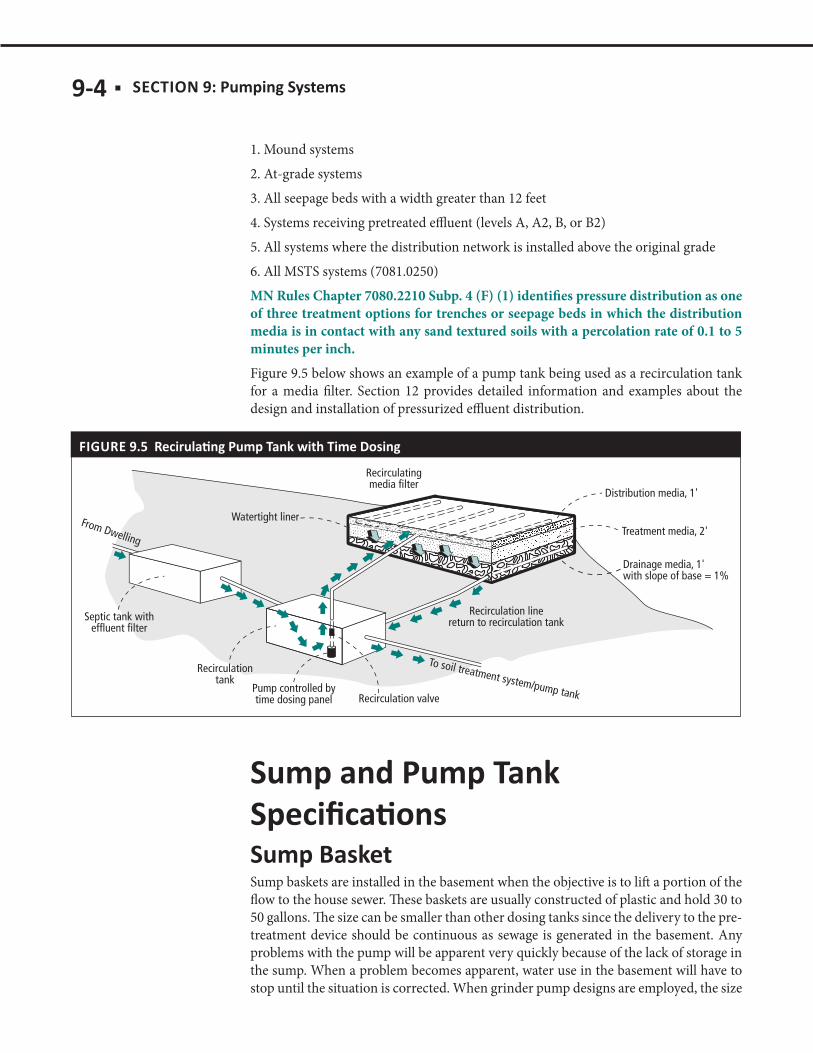
1. Mound systems2. At-grade systems3. All seepage beds with a width greater than 12 feet4. Systems receiving pretreated effluent (levels A, A2, B, or B2)5. All systems where the distribution network is installed above the original grade6. All MSTS systems (7081.0250)MN Rules Chapter 7080.2210 Subp. 4 (F) (1) identifies pressure distribution as one of three treatment options for trenches or seepage beds in which the distribution media is in contact with any sand textured soils with a percolation rate of 0.1 to 5 minutes per inch. Figure 9.5 below shows an example of a pump tank being used as a recirculation tank for a media filter. Section 12 provides detailed information and examples about the design and installation of pressurized effluent distribution.
FIGURE 9.5
Sump baskets are installed in the basement when the objective is to lift a portion of the flow to the house sewer. These baskets are usually constructed of plastic and hold 30 to 50 gallons. The size can be smaller than other dosing tanks since the delivery to the pre-treatment device should be continuous as sewage is generated in the basement. Any problems with the pump will be apparent very quickly because of the lack of storage in the sump. When a problem becomes apparent, water use in the basement will have to stop until the situation is corrected. When grinder pump designs are employed, the size
SECTION 9: ■ 9-5
of the sump basket does not change; however, size becomes more important if there are problems and the pump must be easily and quickly exchanged.
The sump’s specifications are important to its function as part of a pumping system. Sump design must follow MN Rules Chapter 4715.2440, “Design of Sumps,” which is outlined below. People working on these types of applications must be certified plumb-ing contractors under Minnesota Statutes Chapter 326B.46.
As specified in Subpart 1, sumps and receiving tank shall be constructed of poured concrete, metal, or other approved materials. If constructed of poured concrete, the walls and bottom shall be adequately reinforced and designed to acceptable standards. Metal sumps or tanks shall be thick enough to serve their intended purpose and shall be treated both internally and externally to resist corrosion.
Subpart 2 states that the discharge line from the pumping equipment shall be provided with an accessible backwater valve and gate valve, and if the gravity drainage line to which the discharge line connects is horizontal, the two shall be connected from the top through a wye branch fitting. The minimum size of any pump or discharge pipe from a sump connected to a water closet shall be at least two inches.
Building drains or building sewers receiving discharge from any pumping equipment shall be adequately sized to prevent overloading. In all buildings (except single and two-family dwellings), if three or more water closets discharge into the sump, duplicate pumping equipment shall be installed (Subp. 3).
Subpart 4 states that sumps and receiving tanks must be provided with gastight covers, except that float control or switch rods must operate without binding. The cover must be of a bolt and gasket type or equivalent manhole opening to permit access for inspec-tion, repairs, and cleaning. Covers must be metal or other structurally sound material that is water-resistant and impervious to moisture, and must be adequate to support anticipated loads in the area of use.
In single-family dwellings the minimum capacity of a sump shall be 18 gallons (Subp. 5).
According to Subpart 6, the top of the sump tank shall be provided with a vent pipe that shall extend separately through the roof, or may be combined with other vent pipes. Such vent shall be large enough to maintain atmospheric pressure within the sump under all normal operating conditions and in no case less than in accordance with the number of fixture units discharging into the sump. When the foregoing requirements are met and the vent, after leaving the sump, is combined with vents from fixtures dis-

9-6 ■ SECTION 9:
charging into the sump, the size of the combined vent need not exceed that required for the total number of fixtures discharging into the sump. No vent from an air-operated sewage ejector shall combine with other vents.
These types of sumps must not be hooked to an SSTS, as shown in Figure 9.6. When they are in-stalled and discharged to alternate locations, Sub-part 7 states that sumps and receiving tanks which receive only clear water drainage, and from which sewage is excluded, need not be airtight or vented. Sumps and receiving tanks must be provided with covers fastened or secured so as to prevent entry by children. The covers must be adequate to support anticipated loads in area of use. In nonresidential buildings, guard rails constructed in accordance with Chapter 1305, Minnesota Building Code, may be used in lieu of covers.
A pump should never be installed directly in a sep-tic tank to pump to the final soil treatment unit. There is a large risk that sewage solids will plug ei-ther the pump or be carried to the soil treatment unit, which will cause premature failure. Install a two-compartment septic tank or use a separate wa-tertight tank beyond the septic tank. Under these conditions, solids will be separated in the septic tank, and the pump will handle only sewage efflu-ent, which is a relatively clear liquid. Some propri-etary products utilize a pump vault to protect the pump as shown in Figure 9.7. This application still typically follows a separate septic tank.
A pump tank is a sewage tank or separate com-partment within a sewage tank, which receives sewage tank effluent, that serves as a reservoir for a pump. A separate tank used as a pump tank is considered a septic system tank under Minnesota Statutes, section 115.55, subdivision 1, paragraph
(p). (MN Rules Chapter 7080.1100, Subp. 64). Pump tanks may also be referred to as “dosing chambers” and these terms are inter-changeable. A pump tank or dosing chamber is the tank where the effluent from a septic tank or other pretreatment device is stored to be pumped to the next component in the system. The chamber can be a separate tank (as shown in Figure 9.8), a second compartment in a septic tank, or in some media filter designs, it is incorporated into
FIGURE 9.7
FIGURE 9.6

SECTION 9: ■ 9-7
the sump at the bottom of the filter. It is very important that a compartmented tank with a transfer hole in the clarified zone as described in 7080.1950(B) not be used as a pump tank. The size of the tank is determined by the total daily flow, should be large enough to supply the dose volume, and should provide some reserve capacity to provide time for maintenance if the pump fails to operate. The pump tank should have a capacity of at least 500 gallons, or be large enough to hold the average daily sewage flow from the establishment, whichever is greatest. The pump tank must either include an alternating two pump system or have a minimum total capacity of 500 gallons for average daily flow values of 600 gallons per day or less, or 100 percent of the average daily flow for av-erage daily flow values of greater than 600 gallons per day. A 500 gallon tank is allowed for a home with a maximum of four bedrooms. If the home is too large, alternating pumps can substitute the additional required volume in the pump tank. Pump tanks can be round or rectangular. A riser to the ground surface is needed for access to the pump. The pump in a pump tank should be set 4 inches off the tank bot-tom to provide storage space for any solids that may have carried over from the septic tank. At least two four-inch to eight-inch concrete blocks make a good pedestal for the pump. In some systems the solids may accumulate in the pump tank. In these systems the pump intake level is critical to minimize solids entering the system. To increase the pump intake a pump basket may be added to the system. This is a basket surrounding the pump and drawing effluent from a higher elevation. Be careful that the floats do not accumulate around the lip of the pump basket.
The pump tank construction requirements are the same as for sewage tanks since they are defined as such in 7080.1100, Subp. 74. The tank must be durable and watertight
FIGURE 9.8
9-8 ■ SECTION 9:
and must withstand the soil loads, which tend to push in on the walls. The environment in the tanks is very corrosive, so no metal parts or fittings should be used. The major difference between a septic tank and a pump tank is that the pump tank is emptied on a daily basis. Since the tank will be filled and drawn down every day, anchoring it against flotation is critical in areas with a high seasonal or permanent water table, where mound systems, which require pressure distribution, are often used. MN Rules Chapter 7080.2100, Subp. 2 identify that:
A. Pump tanks shall meet or exceed the requirements of parts 7080.1910, 7080.1970, and 7080.1980 to 7080.2020. All pump tanks must be vented.
B. The pump, pump controls, and pump discharge line must be installed to allow access for servicing or replacement without entering the pump tank.
C. The pump tank must either include an alternating two-pump system or have a minimum total capacity of 500 gallons for design flow values of 600 gal-lons per day or less or 100 percent of the design flow for design flow values of greater than 600 gallons per day.
D. An ISTS with a pump must employ an alarm device to warn of failure.E. The inlet of pumps must be elevated at least four inches from the bottom of
the pump tank or protected in some other manner to prevent the pump from drawing excessive settled solids.
F. Electrical installations must comply with applicable laws and ordinances including the most current codes, rules, and regulations of public authori-ties having jurisdiction and with part 1315.0200, which incorporates the Na-tional Electrical Code.
The pump tank is placed between the sewage tank and the lateral system to accumu-late effluent. A pump is turned on when enough effluent collects in the pump tank, and turns off when the dose has been delivered. In demand-dose systems, the pump is controlled by a set of float switches suspended in the tank. Setting the floats is usually accomplished with a float tree. There is an on switch and an off switch. A third switch is used to trigger an alarm to warn the user when the effluent collected in the pump tank reaches a water level above normal operation. This indicates there has been a pump malfunction. Proper pump tank construction, placement and sizing must be consid-ered to ensure reliable system operation.
A pump system can be dosed either on demand or according to a timer as discussed in the next section. The configurations used for each of these regimes are specific and should not be altered without consulting the designer. All ISTS with pumps must be alarmed and provide flow measurement (MN Rules Chapter 7080.2100 Subp. 2 (D)).
Demand dosing is a common method used for delivering effluent to the final treatment and dispersal component. The pump activates when a volume of effluent fills the pump tank to a prescribed level and is solely dependent on the amount of water used in the dwelling or facility. Each time the pump is activated, a designated volume of wastewater
SECTION 9: ■ 9-9
is delivered based upon the float elevations and the tank size. This is the simplest form of dosing but results in variable delivery of effluent to the following component of the system.The most basic form of demand dosing is a float-operated, motor-rated switch into which the pump is plugged. The float is a single wide-angle or differential float control and the configuration is usually called a “piggyback control”. Although still specified and used in some areas, this configuration provides no information on system perfor-mance if meters or counters are not included. These can be temporarily wired into the panel (by qualified personnel) for troubleshooting purposes. If the system has only piggyback controls, an upgrade to a control panel should be strongly recommended to facilitate data collection during operation and maintenance over the course of system use. Certainly, a high water alarm float switch should be wired into the panel to signal excessive hydraulic loading. In a demand dosing system, the on/off function can be performed by a single wide-angle (differential) float control. Because a single float has a limited lower and upper operating range two separate floats should be used for pump on and pump off function if a very small or very large dose is required. In this configuration, the pump activates when the effluent rises to the on float elevation, pumps effluent down to the off float elevation, and then deactivates. An additional float should be included to trigger an audible and visible alarm if flow exceeds capacity. A counter that records alarm events is desirable.In duplex systems, two pumps are alternately activated. When effluent rises to the pump on elevation, pump 1 is activated and delivers the dose volume. The next time a dose is called for, pump 2 is activated, etc. If one pump fails or if flows into the pump tank are excessive, the effluent level rises to the level of the lag switch which activates the resting pump. To provide early indication of excessive flows, the alarm switch may be positioned below the lag switch or the two may be combined. A cycle counter should be included in the control panel to track alarm events.
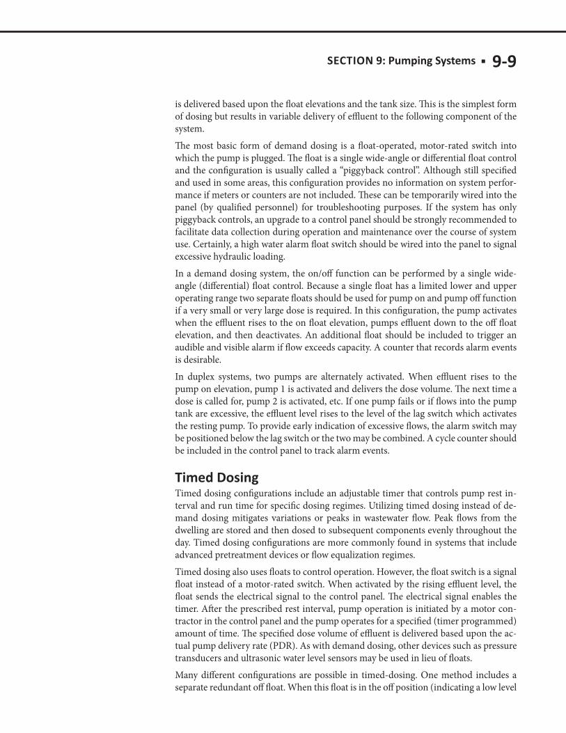
Timed dosing configurations include an adjustable timer that controls pump rest in-terval and run time for specific dosing regimes. Utilizing timed dosing instead of de-mand dosing mitigates variations or peaks in wastewater flow. Peak flows from the dwelling are stored and then dosed to subsequent components evenly throughout the day. Timed dosing configurations are more commonly found in systems that include advanced pretreatment devices or flow equalization regimes.Timed dosing also uses floats to control operation. However, the float switch is a signal float instead of a motor-rated switch. When activated by the rising effluent level, the float sends the electrical signal to the control panel. The electrical signal enables the timer. After the prescribed rest interval, pump operation is initiated by a motor con-tractor in the control panel and the pump operates for a specified (timer programmed) amount of time. The specified dose volume of effluent is delivered based upon the ac-tual pump delivery rate (PDR). As with demand dosing, other devices such as pressure transducers and ultrasonic water level sensors may be used in lieu of floats.Many different configurations are possible in timed-dosing. One method includes a separate redundant off float. When this float is in the off position (indicating a low level
9-10 ■ SECTION 9:
of effluent in the tank), it protects the pump by not allowing it to operate, regardless of the pumping schedule set on the timer. Timer enable and redundant off function may be controlled by the same float. Another option is a configuration that includes a peak enable float installed between the timer enable float and the alarm float. When activated during high flow events, a peak enable float shortens the rest period between normal doses. As a result, more dosing events occur each day and reduce the effluent level in the tank more quickly. Peak enable and alarm function may be controlled by a single float. Note that systems which include peak enable floats are set so that forward flow does not exceed the capacity of the next component or the design flow of the sys-tem. Again, a cycle counter should be included to track the number of times the peak enable float is activated. A timer override float is a differential switch that delivers a different volume to the next component. It essentially (and temporarily) changes the function of the timed dosed system to a demand-dosed regime until the effluent in the tank is reduced to a normal operating level. These are not recommended because they can defeat the purpose of the timer system. It is critical that a counter is included to track how often a timer override float is activated because this indicates how often the system has been hydraulically overloaded. Whether or not the float or sensor that operates the alarm is combined with other floats, the alarm should consist of an audible device and an easily visible light. It should be wired on an electrical circuit separate from the pump. Without a separate circuit, the pump can overload the circuit and the alarm will not operate.
When effluent is pumped from one system component to another, there is an increased need for management. Flow equalization is a management concept that can help reduce stress on system performance due to high peak flows. In flow equalization, the peak flows are stored for a period of time to be delivered to the soil treatment unit over a longer period of time. Usually the flow for one day is equalized over a 24 hour period, but it can be done for longer periods of time, especially if peak flows last for longer than one full day. For this to be accomplished, the tank must be large enough to handle these flows, and the pump operation should be controlled by a timer as opposed to a float. The pump tank capacity for a single family residence using flow equalization is a minimum of 1,000 gallons or two times the daily design flow, whichever is largest. For non-domestic systems, there are two values that need to be calculated to determine storage requirements, design flow and required storage (plus a 20% safety factor).The sum of these values is used to determine the required capacity. To use these values, real flow data (daily flow values) is necessary for the design of the system. The average flow is the calculated average for the daily flow reading for a cer-tain time period. Typically, 45-90 days of data will give a clear idea of the use at the site. Regular events should be factored into the flow equalization design. Annual events can be dealt with using other methods of flow control such as portable toilets or pumping. The storage is calculated as the sum of the flows above the average that needs to be held in the system.
SECTION 9: ■ 9-11
There are several factors to consider when selecting the proper pump for use in onsite wastewater treatment systems. The main factors are the solids handling capability of the pump and flow/pressure relationships within the system. Solids handling and ef-fluent are the two main types of pumps used for sewage purposes. Clean water sump pumps should not be used in sewage applications because they are not designed to withstand the corrosive environment of onsite wastewater treatment systems.
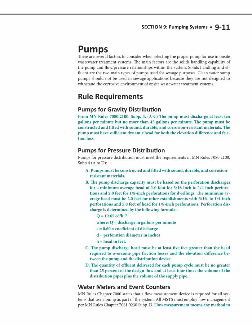
From MN Rules 7080.2100, Subp. 3, (A-C) The pump must discharge at least ten gallons per minute but no more than 45 gallons per minute. The pump must be constructed and fitted with sound, durable, and corrosion-resistant materials. The pump must have sufficient dynamic head for both the elevation difference and fric-tion loss.
Pumps for pressure distribution must meet the requirements in MN Rules 7080.2100, Subp 4 (A to D):
A. Pumps must be constructed and fitted with sound, durable, and corrosion-resistant materials.
B. The pump discharge capacity must be based on the perforation discharges for a minimum average head of 1.0 foot for 3/16-inch to 1/4-inch perfora-tions and 2.0 feet for 1/8-inch perforations for dwellings. The minimum av-erage head must be 2.0 feet for other establishments with 3/16- to 1/4-inch perforations and 5.0 feet of head for 1/8-inch perforations. Perforation dis-charge is determined by the following formula:
Q = 19.65 cd2h1/2
where: Q = discharge in gallons per minute c = 0.60 = coefficient of discharge d = perforation diameter in inches h = head in feet.C. The pump discharge head must be at least five feet greater than the head
required to overcome pipe friction losses and the elevation difference be-tween the pump and the distribution device.
D. The quantity of effluent delivered for each pump cycle must be no greater than 25 percent of the design flow and at least four times the volume of the distribution pipes plus the volume of the supply pipe.
MN Rules Chapter 7080 states that a flow measurement device is required for all sys-tems that use a pump as part of the system. All MSTS must employ flow management per MN Rules Chapter 7081.0230 Subp. D. Flow measurement means any method to

9-12 ■ SECTION 9:
accurately measure water or sewage flow, including, but not limited to, water me-ters, event counters, running time clocks, or electronically controlled dosing (MN Rules Chapter 7080.1100 Subp. 35.). For systems that have effluent pumped to a soil treatment system, an electrical event counter or running time clock is an easy way to meet this rule requirement. Section 1 discusses the importance of using the flow measurement device in your conversation with the system owner about the acceptable use of their septic system. For MSTS systems in MN Rules 7081.0260 (C).The pump discharge capacity must be based on the perforation’s discharge, with a minimum average head of two feet for 1/4 inch and 3/16 inch perforations and five feet for 1/8 inch perforations.
It is important to select the right kind of pump for the desired application. Following is a brief description of pump choices and applications.
Solids handling pumps are positioned before septic tanks and move raw, unsettled waste-water. Grinder pumps are a type of solids handling pump that incorporate a grinder or shredder in the impeller design. Grinder pumps that discharge directly into septic tanks disrupt critical settling processes because they disperse small particles at considerable force. Treatment trains that include grinder pumps must be designed to mitigate this effect or solids bypass will occur to the detriment of the rest of the system. If a grinder pump is specified, the design should include appropriate measures to avoid excessive sol-ids suspension. Options include:
■ Pumping to the inlet pipe instead of directly to the septic tank ■ Pumping to a tank installed prior to the septic tank
Whenever sewage solids are pumped, a sewage ejector or solids-handling pump must be used. The diameter of the discharge piping must be of the same diameter as the dis-charge size of the pump. The sewage must flow through the pipe at a velocity of at least two feet per second to transport the solids. 1. Grinder pumps can also handle raw sewage. A rotating blade shears or grinds sew-
age into smaller particles before pumping it. Grinder pumps have a high starting torque and must use a particular type of starting mechanism on the electric motor. In addition, grinder pumps require relatively high maintenance, such as sharpen-ing blades and replacing bearings. Since all sewage must pass through the grinding mechanism, a grinder pump may experience blockage as the grinding mechanism becomes dull or is clogged by foreign debris.
2. Effluent pumps require that the wastewater be relatively free of solids. They are positioned after septic tanks or within a screened pump vault located at the outlet end of the septic tank. Most effluent pumps use centrifugal force to push the liquid through the pump. Single- and multi-stage pumps provide a broad range of pres-sure and flow options for use with various systems. Low head pumps (single-stage) provide a relatively large rate of flow at a lower pressure. High head (multi-stage) pumps provide a relatively lower rate of flow at a greater pressure. Multi-stage pumps are more sensitive to the amount and size of solids in effluent.
SECTION 9: ■ 9-13
Both types of pumps are cooled by the effluent around them. The intake for single-stage pumps is typically located at the bottom of the housing and below the motor. Single-stage pumps are filled with oil that dissipates heat to the pump housing which is then cooled by the surrounding wastewater. The intake for a multi-stage pump may be located above the motor at the mid-point of the pump housing. Such pumps often use a “flow inducer.” This may be a manufacturer- or designer-specified PVC pipe that surrounds the pump. The pipe is slotted at the bottom which forces effluent to flow around the motor before entering the intake. Alternately, if the pump is designed so that the motor is in the path of the flow a flow inducer is not needed. Setting the pump off elevation above the top of all pump housings is imperative to allow them to cool by remaining submerged in effluent. This also prevents corrosion of the housing by mini-mizing exposure to corrosive gases. High head and low head pumps have different uses in onsite wastewater treatment sys-tems. Typically, high head pumps are required when moving effluent to high elevations and/or through long supply lines where loss of pressure due to friction in pipe and fit-tings is an issue. Low head pumps (single-stage) move more flow at less pressure than high head pumps and are used when those needs arise.
1. Sump pumps are typically used in basements to pump groundwater from around foundations. These pumps should not be used to pump sewage effluent.
2. Ejector pumps are commonly installed in basements to pump sewage solids up to a gravity sewer line. The volume of the pump tank must be large enough to accom-modate any drainback from the piping and to effectively dose the system. When-ever such a pump is used to deliver toilet waste to a septic tank, dose volume must be limited to minimize the impact on the tank.
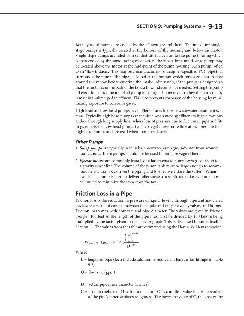
Friction loss is the reduction in pressure of liquid flowing through pipe and associated devices as a result of contact between the liquid and the pipe walls, valves, and fittings. Friction loss varies with flow rate and pipe diameter. The values are given in friction loss per 100 feet so the length of the pipe must first be divided by 100 before being multiplied by the factor given in the table or graph. This is discussed in more detail in Section 11. The values from the table are estimated using the Hazen-Williams equation:
Friction Loss = 10.46L
Q__CD4.871
( )1.852
WhereL = length of pipe (feet; include addition of equivalent lengths for fittings in Table
9.2)Q = flow rate (gpm)
D = actual pipe inner diameter (inches) C = friction coefficient (The friction factor - C) is a unitless value that is dependent
of the pipe’s inner surface’s roughness. The lower the value of C, the greater the
9-14 ■ SECTION 9:
friction loss. Values for the friction factor for PVC pipe range from 130 to 150. For new pipe, 150 is often used as the factor. This manual assumes that with time the pipes will become less smooth resulting in a lower friction factor so a value of 130 was used in estimating the friction loss in tables).
Note: The smaller the pipe diameter and the greater the flow rate, the more friction loss in a given length of pipe.
Friction Loss Example:What is the friction loss generated by liquid flowing at 32 gpm through 100 feet of 1 1/2-inch Schedule 40 PVC, assuming C=130?
Friction loss (ft) = 10.46 x 100 x [(32/130)1.852] / (1.54.871) = 1046 x (.2461.855) / 7.21 = 1046 x .075/7.21 = 10.9 ft of friction loss
Sensor is the general term used for all the different devices used to sense water levels in the tank and activate the pump, including ultrasonic sensors, or using sound to measure depth. Another option is pressure sensors, which use the pressure created by the depth of water to determine the depth. These pressure sensors are valuable since they can read out the actual depths. However, the most commonly used and simple device is a float. Control switches (floats) sense the water level in the pump tank and signal the pump or alarm system. A failure of the control switches can cause sewage to back up into the home or come out the top of the pump tank. Some switches provide power to the pump directly, while others require a relay. Mechanical switches or floats encased in plastic or neoprene are recommended. They are simple and reliable. In some designs, the system uses a single float to operate the pump. In other designs, two floats are used to operate the pump. In two float situations, one switch turns the pump on and a second switch is placed below it to turn the pump off. A third switch is used to activate an alarm if the effluent level exceeds the storage capacity. The distance needed between the on and off switches for a given dose volume depends on the size and shape of the pump tank.
The cables that connect to the pump control switch, alarm switch, and pump all origi-nate from the pump and alarm control. The control should either be placed inside a nearby building or inside a weatherproof box on a post near the entrance port to the pump tank. Never place the control system inside the pump tank or riser. The moisture in the pump tank will cause the system to corrode and fail. The preferred location for the control and alarm center is indoors, such as in a base-ment or garage. Conventional indoor wiring material may be used. Order pump and controls with extra-long cables. When a nearby building is not available, locate the con-trol center in a weatherproof enclosure mounted to a treated wood or steel post near the pump tank. In either case, it is important to use wire, connectors, and weatherproof enclosures appropriate for outdoor use.
SECTION 9: ■ 9-15
A pump motor relay with built-in motor overcurrent protection can be used. The pump motor start and stop switches control the relay coil current. Conduit is used for physi-cal protection of the conductors and cables entering and leaving the box. A pump motor controlled by the mercury switches and relay built into a plug-in type unit is another option. Overcurrent protection for the motor is supplied by the ground-fault circuit interrupter (GFCI)/circuit breaker combination in a weatherproof enclo-sure. National Electric Code requirements state that all outdoor outlets of a residence must be GFCI-protected. The GFCI-protected receptacle for the pump power and control circuit should be enclosed in a watertight box. Another alternative is to use a receptacle with built-in GFCI protection and a standard circuit breaker. In either configuration, the alarm system is powered from a separate circuit breaker to prevent tripping the alarm circuit when the pump circuit is tripped. Schematics and additional discussion about pump controls can be found above Figure 9.16 on pg. 26.
AlarmAn ISTS with a pump must employ an alarm device to warn of failure. Alarm device is defined as a device that alerts a system operator or system owner of a component’s status using a visual or audible device; an alarm device can be either on site or re-motely located (MN Rules Chapter 7080.1100, Subp. 4).An alarm float should be located on an electrical circuit separate from the pump to alert the homeowner in case of electrical failure in the pump circuit. The alarm float should be set to activate approximately three inches higher than the pump start level. It is recommended that the alarm mechanism should be both visible and audible, and located where it can be easily seen and heard. The reserve capacity of the tank is the remaining volume after the alarm sounds. This volume can then be recorded and allows the owner a time period within which the maintainer must come to correct the issue causing the alarm to sound.
The alarm system must be powered in such a way that if the pump circuit fails, the alarm will still operate. Provide a means to turn off the alarm without losing power to the pump.
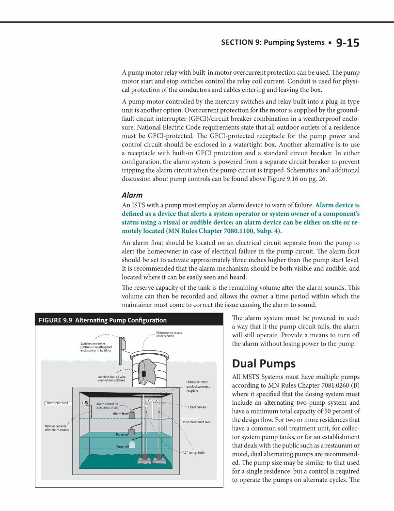
All MSTS Systems must have multiple pumps according to MN Rules Chapter 7081.0260 (B) where it specified that the dosing system must include an alternating two-pump system and have a minimum total capacity of 50 percent of the design flow. For two or more residences that have a common soil treatment unit, for collec-tor system pump tanks, or for an establishment that deals with the public such as a restaurant or motel, dual alternating pumps are recommend-ed. The pump size may be similar to that used for a single residence, but a control is required to operate the pumps on alternate cycles. The
FIGURE 9.9
9-16 ■ SECTION 9:
pump control mechanism also has an alarm device in case one pump fails to operate when called upon. A dual pump configuration is shown in Figure 9.9 (previous page).If liquid flows into the pumping tank faster than one pump can handle, both pumps should operate. If one pump fails, an alarm will sound, and the other pump will contin-ue in service until repairs can be made. Note that an alarm device must also be installed on a separate electrical circuit, so that if a power failure occurs in the pump circuit, and the alarm on the pump control mechanism does not operate, an alarm still will sound.
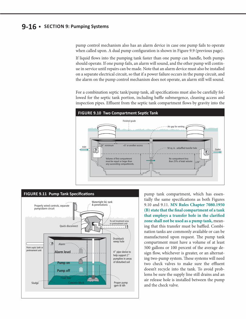
For a combination septic tank/pump tank, all specifications must also be carefully fol-lowed for the septic tank portion, including baffle submergence, cleaning access and inspection pipes. Effluent from the septic tank compartment flows by gravity into the
pump tank compartment, which has essen-tially the same specifications as both Figures 9.10 and 9.11. MN Rules Chapter 7080.1950 (B) state that the final compartment of a tank that employs a transfer hole in the clarified zone shall not be used as a pump tank, mean-ing that this transfer must be baffled. Combi-nation tanks are commonly available or can be manufactured upon request. The pump tank compartment must have a volume of at least 500 gallons or 100 percent of the average de-sign flow, whichever is greater, or an alternat-ing two-pump system. These systems will need two check valves to make sure the effluent doesn’t recycle into the tank. To avoid prob-lems be sure the supply line still drains and an air release hole is installed between the pump and the check valve.
FIGURE 9.11
FIGURE 9.10

SECTION 9: ■ 9-17
Selection of the pump is based upon the configuration of pipes the pump will be con-nected to, the elevation that must be overcome, and the flow requirements for the sys-tem.
A pump curve describes the amount of total dynamic head (TDH) a given pump can overcome at various flows while a system curve describes the TDH in a given system over a range of flows. Pump manufacturers develop pump curves by documenting ac-tual pump operation of each model of pump that they sell.
Figure 9.12 shows performance characteristics of four different submersible pumps. The head-discharge relationship of a pump is called the characteristic curve. The low-est curve represents the pump with the least power and the top curve the pump with most power for a particular pump series. Each pump will operate on its own charac-
FIGURE 9.12
9-18 ■ SECTION 9:
teristic curve, and the curve describes the pump in two ways: the desired capacity in gallons per minute or per hour, and the total dynamic head, the amount of elevation the pump can deliver. As the discharge rate increases, the amount of head a centrifugal pump delivers will decrease. The point where the characteristic curve intersects the vertical axis is called the shutoff head. The point describing the necessary capacity and total dynamic head must fall under the curve. If it doesn’t, choose a different pump.Referring to the example pump curves in Figure 9.12, if pumping requirements are 20 gallons per minute at 20 feet of total dynamic head, none of the pumps presented in Figure 9.12 will deliver precisely this specification. If exactly 20 gallons per minute are needed, a gate valve will need to be installed to dissipate a small amount of head so that the actual head delivered by the pump will be approximately 20 feet. If the 1/2-hp-b high-head pump is used, and 20 feet of head are required, the pump will deliver 45 feet of total head and 25 feet of the head will be dissipated in the gate valve. When the pump discharge is to a pressure distribution system in a mound, this system is self-balancing. As the flow increases, pressure at the perforations also increases, and the pump will operate at some point on its own particular characteristic curve. There is no need to install a gate valve with a pressure distribution system.Refer to the form on the website, septic.umn.edu/ssts-professionals/forms-worksheets, to follow this design process.
a. Choosing a Pump for a Gravity-Distribution Soil Treatment SystemBecause pump capacity needs to be greater than the domestic water use rate, a minimum flow of 600 gallons per hour, which is equivalent to 10 gallons per min-ute, is required when a pump used for a dwelling discharges to a gravity-fed soil treatment system. When choosing a pump, look at the pump curve to deliver at
least 15 feet of head at the elevation difference. For most pumps this will guarantee at least 10 gpm when the fric-tion loss is included.The maximum discharge rate for delivery to a drop box of a dwelling’s sewage system is 45 gallons per minute, which is the approximate amount that will flow by grav-ity through a four-inch pipe. Choosing a pump that delivers at or less than 45 gpm at the elevation differ-ence will minimize substantial head in the drop box. It would not be good practice to develop any substantial head in a drop box. Follow specifications provided in Figure 9.13.The sizing procedure is to measure the elevation differ-ence. Applying this as the head loss to the pump curve and then making sure the pump capacity is between 15-45 gpm, the system will work effectively.b. Choosing a Pump for Pressure-Distribution Soil Treatment SystemsIn a pressure distribution system, the required gallons per minute is set by the configuration and perforation sizing in the system. Refer to Section 12 on Distribu-tion and the Pressure Distribution Worksheet for more information.
FIGURE 9.13
SECTION 9: ■ 9-19
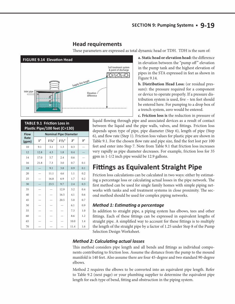
These parameters are expressed as total dynamic head or TDH. TDH is the sum of:a. Static head or elevation head: the difference in elevation between the “pump off ” elevation in the pump tank and the highest elevation of pipes in the STA expressed in feet as shown in Figure 9.14.b. Distribution Head Loss: (or residual pres-sure): the pressure required for a component or device to operate properly. If a pressure dis-tribution system is used, five – ten feet should be entered here. For pumping to a drop box of a trench system, zero would be entered.c. Friction loss is the reduction in pressure of
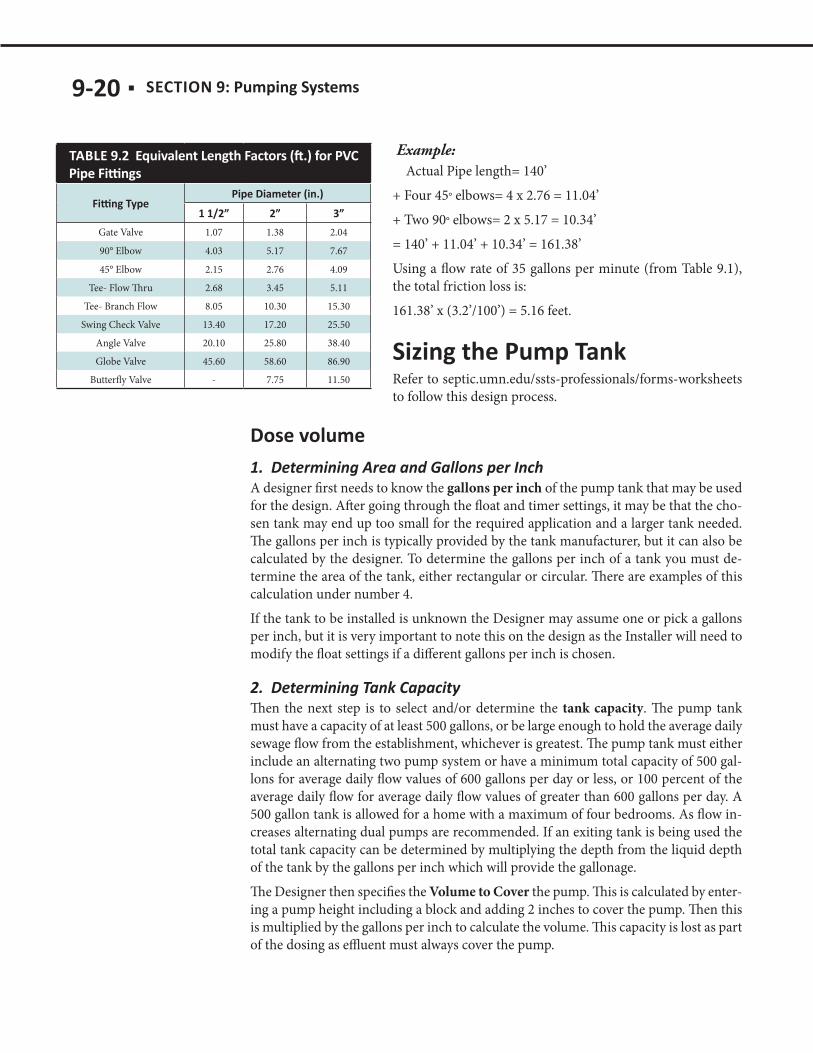
liquid flowing through pipe and associated devices as a result of contact between the liquid and the pipe walls, valves, and fittings. Friction loss depends upon type of pipe, pipe diameter (Step 6), length of pipe (Step 6), and flow rate (Step 1). Friction loss values for plastic pipe are shown in Table 9.1. For the chosen flow rate and pipe size, find the feet lost per 100 feet and enter into Step 7. Note from Table 9.1 that friction loss increases very rapidly as pipe diameter decreases. For example, friction loss for 35 gpm in 1-1/2 inch pipe would be 12.9 gallons.
Friction loss calculations can be calculated in two ways: either by estimat-ing a percentage loss or calculating actual losses in the pipe network. The first method can be used for single family homes with simple piping net-works with tanks and soil treatment systems in close proximity. The sec-ond method should be used for complex piping networks.
In addition to straight pipe, a piping system has elbows, tees and other fittings. Each of these fittings can be expressed in equivalent lengths of straight pipe. A simplified way to account for these fittings is to multiply the length of the straight pipe by a factor of 1.25 under Step 8 of the Pump Selection Design Worksheet.
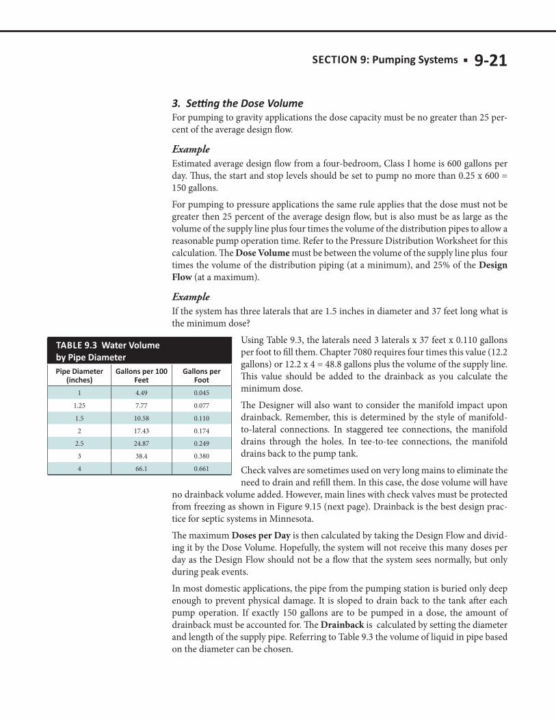
This method considers pipe length and all bends and fittings as individual compo-nents contributing to friction loss. Assume the distance from the pump to the mound manifold is 140 feet. Also assume there are four 45-degree and two standard 90-degree elbows.Method 2 requires the elbows to be converted into an equivalent pipe length. Refer to Table 9.2 (next page) or your plumbing supplier to determine the equivalent pipe length for each type of bend, fitting and obstruction in the piping system.
Flow
1 1 4 1 1 2
10 9.1 3.1 1.3 0.3 —
12 12.8 4.3 1.8 0.4 —
14 17.0 5.7 2.4 0.6 —
16 21.8 7.3 3.0 0.7 0.1
18 — 9.1 3.8 0.9 0.1
20 — 11.1 4.6 1.1 0.2
25 — 16.8 6.9 1.7 0.2
30 — 23.5 9.7 2.4 0.3
35 — — 12.9 3.2 0.4
40 — — 16.5 4.1 0.6
45 — — 20.5 5.0 0.7
50 — — — 6.1 0.9
55 — — — 7.3 1.0
60 — — — 8.6 1.2
65 — — — 10.0 1.4
70 — — — 11.4 1.6
FIGURE 9.14
9-20 ■ SECTION 9:
Example: Actual Pipe length= 140’+ Four 45° elbows= 4 x 2.76 = 11.04’+ Two 90° elbows= 2 x 5.17 = 10.34’= 140’ + 11.04’ + 10.34’ = 161.38’Using a flow rate of 35 gallons per minute (from Table 9.1), the total friction loss is: 161.38’ x (3.2’/100’) = 5.16 feet.
Refer to septic.umn.edu/ssts-professionals/forms-worksheets to follow this design process.
A designer first needs to know the gallons per inch of the pump tank that may be used for the design. After going through the float and timer settings, it may be that the cho-sen tank may end up too small for the required application and a larger tank needed. The gallons per inch is typically provided by the tank manufacturer, but it can also be calculated by the designer. To determine the gallons per inch of a tank you must de-termine the area of the tank, either rectangular or circular. There are examples of this calculation under number 4. If the tank to be installed is unknown the Designer may assume one or pick a gallons per inch, but it is very important to note this on the design as the Installer will need to modify the float settings if a different gallons per inch is chosen.
Then the next step is to select and/or determine the tank capacity. The pump tank must have a capacity of at least 500 gallons, or be large enough to hold the average daily sewage flow from the establishment, whichever is greatest. The pump tank must either include an alternating two pump system or have a minimum total capacity of 500 gal-lons for average daily flow values of 600 gallons per day or less, or 100 percent of the average daily flow for average daily flow values of greater than 600 gallons per day. A 500 gallon tank is allowed for a home with a maximum of four bedrooms. As flow in-creases alternating dual pumps are recommended. If an exiting tank is being used the total tank capacity can be determined by multiplying the depth from the liquid depth of the tank by the gallons per inch which will provide the gallonage.The Designer then specifies the Volume to Cover the pump. This is calculated by enter-ing a pump height including a block and adding 2 inches to cover the pump. Then this is multiplied by the gallons per inch to calculate the volume. This capacity is lost as part of the dosing as effluent must always cover the pump.
Gate Valve 1.07 1.38 2.04
90° Elbow 4.03 5.17 7.67
45° Elbow 2.15 2.76 4.09
Tee- Flow Thru 2.68 3.45 5.11
Tee- Branch Flow 8.05 10.30 15.30
Swing Check Valve 13.40 17.20 25.50
Angle Valve 20.10 25.80 38.40
Globe Valve 45.60 58.60 86.90
Butterfly Valve - 7.75 11.50
SECTION 9: ■ 9-21
For pumping to gravity applications the dose capacity must be no greater than 25 per-cent of the average design flow.
ExampleEstimated average design flow from a four-bedroom, Class I home is 600 gallons per day. Thus, the start and stop levels should be set to pump no more than 0.25 x 600 = 150 gallons. For pumping to pressure applications the same rule applies that the dose must not be greater then 25 percent of the average design flow, but is also must be as large as the volume of the supply line plus four times the volume of the distribution pipes to allow a reasonable pump operation time. Refer to the Pressure Distribution Worksheet for this calculation. The Dose Volume must be between the volume of the supply line plus four times the volume of the distribution piping (at a minimum), and 25% of the Design Flow (at a maximum).
ExampleIf the system has three laterals that are 1.5 inches in diameter and 37 feet long what is the minimum dose?
Using Table 9.3, the laterals need 3 laterals x 37 feet x 0.110 gallons per foot to fill them. Chapter 7080 requires four times this value (12.2 gallons) or 12.2 x 4 = 48.8 gallons plus the volume of the supply line. This value should be added to the drainback as you calculate the minimum dose.The Designer will also want to consider the manifold impact upon drainback. Remember, this is determined by the style of manifold-to-lateral connections. In staggered tee connections, the manifold drains through the holes. In tee-to-tee connections, the manifold drains back to the pump tank. Check valves are sometimes used on very long mains to eliminate the need to drain and refill them. In this case, the dose volume will have
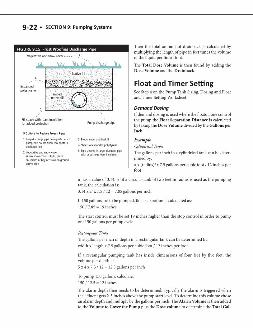
no drainback volume added. However, main lines with check valves must be protected from freezing as shown in Figure 9.15 (next page). Drainback is the best design prac-tice for septic systems in Minnesota.The maximum Doses per Day is then calculated by taking the Design Flow and divid-ing it by the Dose Volume. Hopefully, the system will not receive this many doses per day as the Design Flow should not be a flow that the system sees normally, but only during peak events. In most domestic applications, the pipe from the pumping station is buried only deep enough to prevent physical damage. It is sloped to drain back to the tank after each pump operation. If exactly 150 gallons are to be pumped in a dose, the amount of drainback must be accounted for. The Drainback is calculated by setting the diameter and length of the supply pipe. Referring to Table 9.3 the volume of liquid in pipe based on the diameter can be chosen.
1 4.49 0.045
1.25 7.77 0.077
1.5 10.58 0.110
2 17.43 0.174
2.5 24.87 0.249
3 38.4 0.380
4 66.1 0.661
9-22 ■ SECTION 9:
Then the total amount of drainback is calculated by multiplying the length of pipe in feet times the volume of the liquid per linear foot. The Total Dose Volume is then found by adding the Dose Volume and the Drainback.
See Step 4 on the Pump Tank Sizing, Dosing and Float and Timer Setting Worksheet.
If demand dosing is used where the floats alone control the pump the Float Separation Distance is calculated by taking the Dose Volume divided by the Gallons per Inch.
ExampleCylindrical TanksThe gallons per inch in a cylindrical tank can be deter-mined by:π x (radius)2 x 7.5 gallons per cubic foot / 12 inches per foot
π has a value of 3.14, so if a circular tank of two feet in radius is used as the pumping tank, the calculation is:3.14 x 22 x 7.5 / 12 = 7.85 gallons per inch
If 150 gallons are to be pumped, float separation is calculated as:150 / 7.85 = 19 inches
The start control must be set 19 inches higher than the stop control in order to pump out 150 gallons per pump cycle.
Rectangular TanksThe gallons per inch of depth in a rectangular tank can be determined by:width x length x 7.5 gallons per cubic foot / 12 inches per foot
If a rectangular pumping tank has inside dimensions of four feet by five feet, the volume per depth is:5 x 4 x 7.5 / 12 = 12.5 gallons per inch
To pump 150 gallons, calculate: 150 / 12.5 = 12 inchesThe alarm depth then needs to be determined. Typically the alarm is triggered when the effluent gets 2-3 inches above the pump start level. To determine this volume chose an alarm depth and multiply by the gallons per inch. The Alarm Volume is then added to the Volume to Cover the Pump plus the Dose volume to determine the Total Gal-
FIGURE 9.15
SECTION 9: ■ 9-23
lons. If the Total Gallons is divided by the gallon per inch the Minimum Tank Depth is calculated.Then set the Pump Off-Float by taking the Pump Height +Block Height + 2 inches. The Pump On-Float level should be set at twelve inches above the Pump Off-Float level. This is calculated by taking the Distance for the Off-Float calculated above and adding in the Float Separation Distance. The alarm float height is then the Distance to set the Pump–On Float + Alarm Depth.
When a timer is being used to control the pump the Gallons per Minute of the pump being used must be defined. In most instances this will come from the pressure distri-bution design, but also may be chosen in gravity applications. During installation or on existing systems the gallons per minute must be calculated by performing a draw down test where the change in depth in a tank in inches is recorded over a period of time and multiplied by the gallons per inch of the tank. This is the only way to have an accurate dose.
Timer OnTo calculate the Timer On the Dose Volume is divided by the Gallons per Minute of the pump. This will provide the number of minutes the pump will run each time it turns on. The pump will not activate if sufficient sewage is not present to be dosed.
Timer OffTo determine the Timer Off take the number of minutes in a day (1440) divided by the likely or typical Doses per Day and subtract the Timer On. This will establish the amount of time between doses in minutes. This time may need to be adjusted over time if current usage per day is unknown.The Pump-Off float is still set to cover by taking the Gallons to Cover the Pump and dividing by the Gallons per Inch of the tank.
Ensuring that the pump tank is watertight is critical. In areas with a high seasonal or permanent water table, groundwater may leak into the pump tank and overload the system. The seals around the pipes that enter and exit the pump tank are especially vulnerable to leaks. If the pump is running more than the few minutes a day it takes to pump out the accumulated septic tank effluent, groundwater may be leaking into the septic tank or pump tank. The installation of the riser is the same as discussed in Section 7. The piping may leave through the riser, adding to the importance of proper backfilling. Be sure the pipe is well supported and drains back to the tank. This includes the installation of a weep hole in the supply line in the tank. This ¼-inch hole should be placed on the bottom of the pipe to assure that the supply pipe will drain. It should be placed so minimal standing water is in the pipe. MN Rules Chapter 7080 requires either 100 percent of design flow or dual alternating pumps.
9-24 ■ SECTION 9:
The pipe should be well supported outside the tank. All the components for the dis-charge assembly should be installed and the wiring safely brought into the pump tank. Using the proper size conduit for this is critical. A two to three-inch conduit is neces-sary to allow for the pump to be changed without cutting the cord. Be sure that conduit with sweep 90’s are used to allow for removing and returning the cords. This conduit also needs to be properly sealed to avoid venting of odors and cold air entering the sys-tem. The conduit should be sealed with a removable material such as duct seal. Do not use expandable foam insulation since it cannot be removed.A complete pumping system includes a pump tank, pump and controls. The pump tank must be watertight and constructed of materials that will not corrode or decay. The cleaning access must be installed to the ground surface and securely fastened or locked so that unauthorized persons cannot get into the tank. Pumps are sized accord-ing to the specifications of each system and a specific model should be indicated in the design. A “similar” pump should not be used unless confirmed in writing by the designer.
If the pumping tank is installed where the water table is high, consider the potential prob-lem of tank buoyancy. Be sure the weight of the tank will be adequate to prevent flotation when the tank is nearly empty (which it will be much of the time). Otherwise, anchors may be needed to prevent tank flotation. This issue is discussed in full in Section 7, Septic Tanks.Flotation or buoyancy usually is not a problem with concrete tanks but should be veri-fied for any design and installation. These tanks will be empty at times, so the buoyancy should be checked. The weight of the tank and the cover weight of the soil are the forces keeping the tank the ground. For the lighter weight materials, the manufacturer may have certain requirements. Such tanks are very likely to need anchoring according to manufacturer’s specifications. The use of buried curbing and strapping is a method to assure the tank will not float.A compartmented tank where the first compartment is the septic tank and the second compartment is the pump tank may be employed in some sites. A compartmented tank can help to reduce the buoyancy problem since the septic tank portion is typically full. When a compartmented tank is used, the strength of the inside wall between the septic tank and the pump tank is critical. Since there will be constant water pressure on one side of the wall, the tank needs to be designed to withstand that pressure. Be sure that the septic capacity is adequate for the use. Remember that any solids will impact the pump and the dosing system.
The discharge assembly is made up of all the piping and components from the pump discharge point to the point at which the supply line leaves the tank. The assembly should be accessible and reachable from the ground surface. A length of nylon rope, stainless steel cable, or other non-corrodible material should be attached to the pump to facilitate removal during maintenance activities. It must have sufficient strength to lift the weight of the pump. In larger systems, a corrosion-resistant rail system may be specified. The pump discharge assembly should have a union or other quick-disconnect
SECTION 9: ■ 9-25
coupler to facilitate removal of the pump without having to cut the discharge pipe. This may be a three-part threaded union, a cam lock fitting, or other simple inline discon-nect able to withstand the pressure created by the pump system. Rubber connectors are not designed to withstand the pressure created in these systems.If the elevation of the supply line changes significantly from the tank to the next com-ponent, air may become trapped in the line during rest periods. In this situation, an air release valve should be placed at the highest elevation of the pipe. The valve should be housed in a vault that comes to grade to allow for inspection and maintenance.
There should be no electromechanical devices or connections located in the pump tank or in the pump tank cleaning access. The electrical plug-ins should be located in a weather-proof enclosure near the pumping tank or located in a nearby building. It’s a good idea to attach the control wires to a separate pipe (float tree) and the pump to a plastic rope or chain with an anchor so that the control wires can be removed without removing the pump. Also, if the pump has failed, it can be removed without disturbing the control wires. The access for the pump and other components should come to the finished grade. The pump and components should be located directly under this lid, and easy access to these components for management is a must. The cover of the pumping tank, the cover of the septic tank, and all cleaning access extensions must be made absolutely water-tight to prevent any groundwater from infiltrating the system. Pipe connections to the tanks also must be sealed to be absolutely watertight. Be extremely careful to make sure the supply line from the pump tank does not settle. Additional support is necessary to ensure the system will operate without freezing. Placing the supply line in conduit throughout the area of excavation is a recommended practice.
Pump systems should include a control panel. The control panel can be quite simple or more complex based on the functions it must perform. Electrical components in the panel respond to water level sensors or floats in the tank. The components then perform a variety of basic functions:
■ Automatically turning the pump on and off with a manual override ■ Sounding an alarm to indicate problems ■ Providing a means of monitoring the system (meters/counters) ■ Initiating a telemetry device for system alerts ■ Activation of equipment for remote system operation
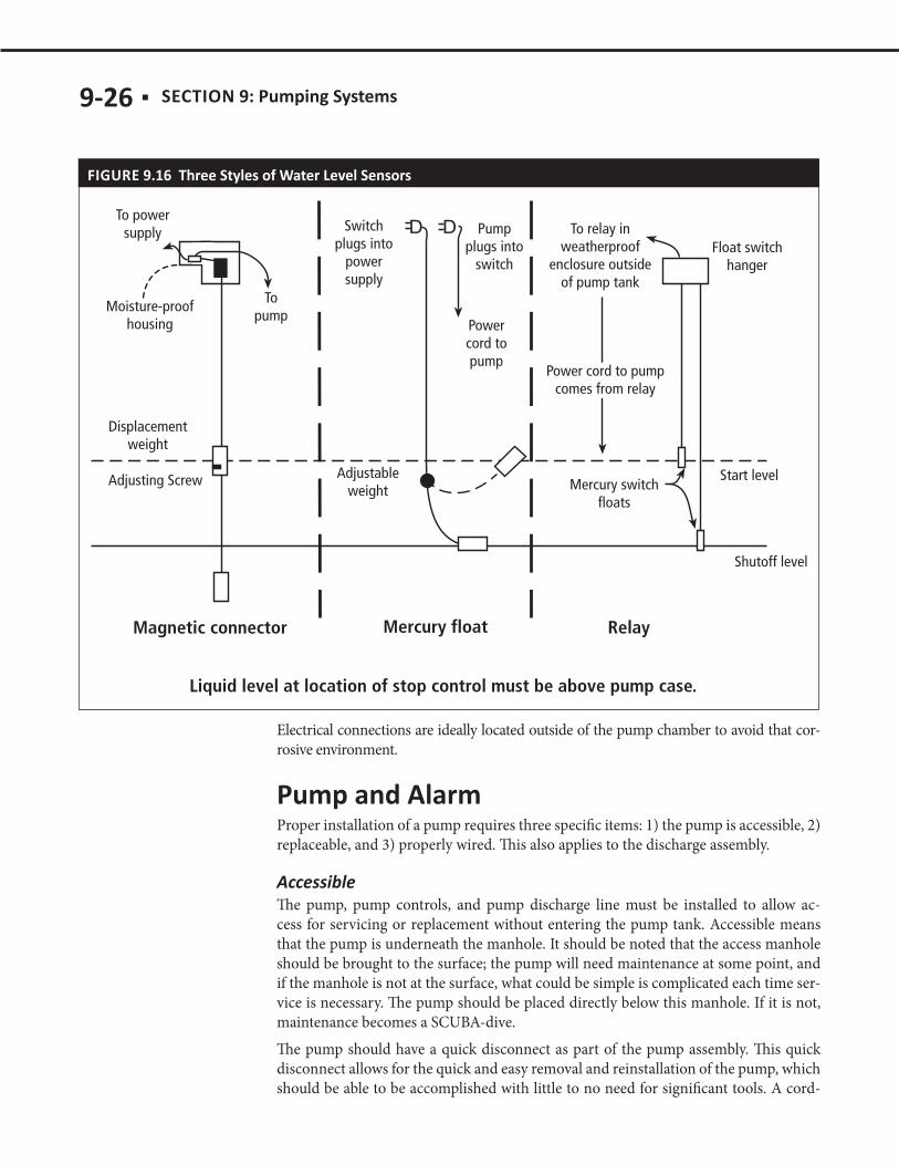
There are several types of devices to achieve these functions as shown in Figure 9.16 (next page).In all cases, electrical components and connections must be properly protected from the elements and from the corrosive environment of the pump tank. Ideally, this is achieved through use of a National Electrical Manufacturers Association (NEMA) 4X enclosure (4X refers to watertight and corrosion protection enclosure) with properly sealed connections.
9-26 ■ SECTION 9:
Electrical connections are ideally located outside of the pump chamber to avoid that cor-rosive environment.
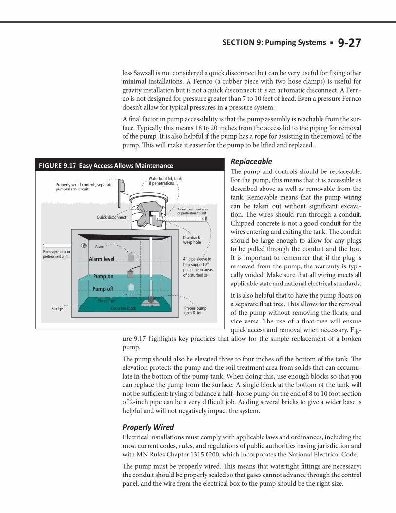
Proper installation of a pump requires three specific items: 1) the pump is accessible, 2) replaceable, and 3) properly wired. This also applies to the discharge assembly.
The pump, pump controls, and pump discharge line must be installed to allow ac-cess for servicing or replacement without entering the pump tank. Accessible means that the pump is underneath the manhole. It should be noted that the access manhole should be brought to the surface; the pump will need maintenance at some point, and if the manhole is not at the surface, what could be simple is complicated each time ser-vice is necessary. The pump should be placed directly below this manhole. If it is not, maintenance becomes a SCUBA-dive. The pump should have a quick disconnect as part of the pump assembly. This quick disconnect allows for the quick and easy removal and reinstallation of the pump, which should be able to be accomplished with little to no need for significant tools. A cord-
FIGURE 9.16
SECTION 9: ■ 9-27
less Sawzall is not considered a quick disconnect but can be very useful for fixing other minimal installations. A Fernco (a rubber piece with two hose clamps) is useful for gravity installation but is not a quick disconnect; it is an automatic disconnect. A Fern-co is not designed for pressure greater than 7 to 10 feet of head. Even a pressure Fernco doesn’t allow for typical pressures in a pressure system. A final factor in pump accessibility is that the pump assembly is reachable from the sur-face. Typically this means 18 to 20 inches from the access lid to the piping for removal of the pump. It is also helpful if the pump has a rope for assisting in the removal of the pump. This will make it easier for the pump to be lifted and replaced.
The pump and controls should be replaceable. For the pump, this means that it is accessible as described above as well as removable from the tank. Removable means that the pump wiring can be taken out without significant excava-tion. The wires should run through a conduit. Chipped concrete is not a good conduit for the wires entering and exiting the tank. The conduit should be large enough to allow for any plugs to be pulled through the conduit and the box. It is important to remember that if the plug is removed from the pump, the warranty is typi-cally voided. Make sure that all wiring meets all applicable state and national electrical standards. It is also helpful that to have the pump floats on a separate float tree. This allows for the removal of the pump without removing the floats, and vice versa. The use of a float tree will ensure quick access and removal when necessary. Fig-
ure 9.17 highlights key practices that allow for the simple replacement of a broken pump.The pump should also be elevated three to four inches off the bottom of the tank. The elevation protects the pump and the soil treatment area from solids that can accumu-late in the bottom of the pump tank. When doing this, use enough blocks so that you can replace the pump from the surface. A single block at the bottom of the tank will not be sufficient: trying to balance a half- horse pump on the end of 8 to 10 foot section of 2-inch pipe can be a very difficult job. Adding several bricks to give a wider base is helpful and will not negatively impact the system.
Electrical installations must comply with applicable laws and ordinances, including the most current codes, rules, and regulations of public authorities having jurisdiction and with MN Rules Chapter 1315.0200, which incorporates the National Electrical Code. The pump must be properly wired. This means that watertight fittings are necessary; the conduit should be properly sealed so that gases cannot advance through the control panel, and the wire from the electrical box to the pump should be the right size.
FIGURE 9.17
9-28 ■ SECTION 9:
The inside of the tank is a very corrosive environment, so the splices or wiring must be protected if the connections are made inside the tank. The sealing of the conduit is also critical. In many states it is required that there is a vent or separation of the conduit from the control panel. Be sure the size of the wire is big enough to meet the power demand of the pump. If the wire is too small the pump will not operate properly and wear out quickly. The proper gauge of the wire is related to the length of wire and the size (horsepower) of the pump. The horsepower of the pump dictates the size of a mo-tor and the electrical draw. If the total distance from the pump to the control panel is too great for the wire size, the pump will not receive the proper amps for the motor. This will cause an early failure. All wastewater distribution systems that utilize a pump require electrical power and control systems. Proper wiring materials and installation procedures are critical to the safety of the installer, the sewage system users, and all individuals involved in future repairs and maintenance. Adequate wiring ensures reliable pump and system perfor-mance. Follow a few basic guidelines to ensure safe and reliable operation at a rea-sonable cost. In all cases, installation procedures must follow the specifications of the U.S. National Electric Code (NEC). Contact local electrical inspection authorities for permits and inspection requirements. Work should be done by a qualified electrical installer. Make no electrical connections inside the pump tank. This includes plug-ins, screw-type, twisted wire, boxes, relays, or any other type of connection that requires move-ment to connect or operate. If connections or splices must be made, they should be located in a watertight, corrosion-resistant junction box with watertight, corrosion-resistant fittings and a cover sealed by a gasket.
The materials and installation procedures for outside wiring are considerably differ-ent from indoor wiring. Outdoor wiring must be able to withstand exposure to water, weather, and corrosive environments. This is certainly the case for wiring septic system pump tanks.
Outdoor equipment used in residential wiring must be weatherproof. The two most common types of weatherproof equipment are driptight and watertight. Driptight equipment seals against water falling vertically. Driptight boxes are usually made of painted sheet metal and have shrouds or shields that deflect rain falling from above. These boxes are not waterproof and should not be used where water can spray or splash on the unit. Driptight boxes are usually used for control or circuit breaker panels. Watertight boxes seal against water coming from any direction. Individual junction boxes, switch boxes and receptacle boxes will usually be of the watertight type. Wa-tertight boxes are designed to withstand temporary immersion or spray streams from any direction. They are commonly made of cast aluminum, zinc-dipped iron, bronze or heavy plastic and have threaded entries for watertight fittings and covers sealed by gaskets.
SECTION 9: ■ 9-29
Power to the pump and alarm system control center, when located outside a building, will most frequently be supplied by an underground branch circuit from a nearby ser-vice entrance or sub-panel. Follow electrical code specifications for materials and buri-al depths as described earlier. Avoid routing buried wiring through existing or antici-pated gardens or landscaping areas to minimize the chances of damage due to spading. Power to the control center should be from a single branch circuit with no other loads. The circuit breaker or fuse supplying this circuit should be clearly marked at the service entrance location. Two methods, or a combination of the two, are common in outdoor wiring. One meth-od is to place electrical wires inside a conduit. The other is to use cable. In either case, protection from physical damage, water, and corrosion must be provided.Running wires through sealed conduit provides physical, water, and corrosion protec-tion. Several kinds of conduit are acceptable for outdoor use. Rigid metal conduit made from aluminum or steel provides equivalent wire protection. However, aluminum con-duit is not recommended for installation where it is directly in contact with soil. Rigid PVC conduit can be used above ground. High-density polyethylene conduit is suitable for underground installation. Do not use thinwall conduit (EMT) for underground or outdoor installations. An underground feeder cable can be buried without conduit protection, but physical protection for underground cable is highly recommended to reduce the risk of spad-ing through the cable at a later time. This is particularly true around the septic tank. A redwood or treated wood board buried just above the cable is highly recommended to provide physical protection. Do not use nonmetallic cable for underground instal-lations. While it is an excellent material for interior wiring, it will not withstand the moisture conditions in the soil. Because electrical components will be used, running power to the area will be critical. Make sure the wire has the proper capacity for the electrical demands of the pump. This is done by comparing the length of wire necessary from the pump to the power box and the horsepower required for the pump. Having these two values allows for proper selection of the wire sizes. A second wire should be run for the alarm and should be on a second circuit. Combining the conduit and cable wiring methods is also an option. Conduit can be used around cable for physical protection. Conduit is particularly useful to protect cables where they enter and exit the soil. If conduit and cable are used in combination, appropriate connectors and bushings are needed for transitions from one system to the other. Minimum burial requirements apply to wire in conduit and cables. The size of the wire is determined from the electrical need (the motor size) and the length of wire. Table 9.4 on the following page gives wire specifications for various lengths and motor ratings.

9-30 ■ SECTION 9:
14 12 10 8 6 4115 1/3 130 210 340 540 840 1300
115 1/2 100 160 250 390 620 960
230 1/3 550 880 1390 2190 3400 5250
230 1/2 400 650 1020 1610 2510 3880
230 3/4 300 480 760 1200 1870 2890
230 1 250 400 630 990 1540 2380
230 1 1/2 190 310 480 770 1200 1870
230 2 150 250 390 620 970 1530
230 3 120* 190 300 470 750 1190
230 5 0 0 180 280 450 710
230 7 1/2 0 0 0 200* 310 490
230 10 0 0 0 160* 250* 390
230 15 0 0 0 0 170* 270*2- or 3-wire cable, maximum length in feet, service entrance to motor* Lengths meet U.S. National Electric Code (NEC) ampacity only for individual conductor 60C cable in free air or water, not in
conduit. If cable rated other that 60C is used, lengths remain unchanged, but minimum size acceptable for each rating must be based on the NEC table column for that temperature cable.
Lengths without asterisks meet NEC ampacity for individual conductors and jacketed 60C cable.Flat molded cable is considered jacketed cable.Maximum lengths shown maintain motor voltage at 95% service entrance voltage, running at maximum nameplate amperes.
If service entrance voltage will be at least motor nameplate voltage under normal load conditions, 50% additional length is permissible for all sizes.
Table based on copper wire. If aluminum wire is used, it must be two sizes larger. If table calls for #12 copper, for example, #10 aluminum would be required.
The power cable to the pump and float switch cables running from the control center into the tank should be run in conduit (metal or PVC) where physical protection is needed. The area around the conduit entering the tank should be sealed to prevent sur-face water from entering the tank through the conduit. If the conduit provides a con-tinuous connection between the control center box and the tank, the conduit entrance to the box should be plugged with electrical putty to prevent the movement of moisture and corrosive gases into the control box. Provide an outlet for the wires through the side of the cleaning access. Consider installing a section of six-inch plastic pipe with a cap alongside the cleaning access to contain the pumping station wires.Power cables used in these installations, such as Types SE, SJ or SOW, must be suit-able for moist and corrosive environments. The power cable to the pump must have a grounding conductor (usually a green insulated wire) to ground the pump motor frame. Metallic conduit should not be used for equipment grounding to or within the tank. Since the pump is considered a motor load, it must have appropriate disconnect-ing means. The disconnect for units of one horsepower or greater (circuit breaker or switch) must be clearly marked and either in sight of the pump location or lockable. This prevents inadvertent reactivation of the circuit during servicing of the unit. Below one hp, receptacles and plugs listed for motor loads (hp listed) may be used.

SECTION 9: ■ 9-31
NEMA stands for National Electrical Manufacturer Association. Their website is at www.nema.org. NEMA ratings are standards that are useful in defining the types of environments in which an electrical enclosure can be used. The NEMA rating system is defined by the National Electrical Manufacturer Association, and frequently signifies a fixed enclosure’s ability to withstand certain environmen-tal conditions. In non-hazardous locations, there are several different NEMA ratings for specific enclosure “types”, their applications, and the environmental conditions they are designed to protect against, when completely and properly installed. The following provides an overview of the NEMA Types. For complete definitions, descriptions, and test criteria, see the National Electrical Manufactur-ers Association (NEMA) Standards Publication No. 250.
NEMA type 1Type 1 enclosures are intended for indoor use primarily to provide a degree of protection against contact with the enclosed equipment in locations where un-usual service conditions do not exist.
NEMA type 3RType 3 enclosures are intended for outdoor use primarily to provide a degree of protection against windblown dust, rain, sleet, and external ice formation.
NEMA type 4Type 4 enclosures are intended for indoor or outdoor use primarily to provide a degree of protection against windblown dust and rain, splashing water, and hose-directed water and external ice formation.
NEMA type 4X non-metallic, corrosion-resistantType 4X enclosures are intended for indoor or outdoor use primarily to provide a degree of protection against corrosion, windblown dust and rain, splashing water, and hose-directed water. Enclosure is manufactured with a synthetic rub-ber gasket between cover and base. This is ideal for such industries as chemical plants and paper mills.
Meeting these requirements—accessible, removable and properly wired will alleviate the majority of problems that could be experienced with pump systems, and will make the pumping system easier to maintain.
According to MN Rules Chapter 7080.2450, Subp. 3 (E), pump tanks must be main-tained according to this part. Sludge must be removed if within one inch of the pump intake.
9-32 ■ SECTION 9:
The amount of energy required for pumping sewage is relatively small. If a pump de-livers 40 gallons per minute and 174 gallons are to be pumped per dose, then pump operating time is 4.35 minutes per cycle with four cycles per day, for a total time of 17.4 minutes per day. The 1/2-hp pump in the example above is about a 1500-watt pump. (The actual nameplate amperage of a pump may be multiplied by the voltage to deter-mine the wattage.) The pump in the example will use approximately 0.44 kilowatt hours per day of operation. Energy costs may be calculated using current prices.
Calculating the amount of flow that reaches various treatment components is critical to assessing performance. Components are designed for a particular flow and if actual flow varies considerably from design flow, results must be interpreted accordingly. In order to calculate the flow through a system, some simple information must be col-lected. The cycle counters, pump dose volumes, elapsed time meters, and pump capaci-ty for both the pretreatment and final dispersal step should be documented. If available, water meter readings for the structure are helpful to estimate incoming flows.The pump dose volume is related to either the float settings (dose volume) or the timer settings for that system. In a timed dosed system, the pump flow (gpm) multiplied by the pump run time (minutes) equals the total volume that the pump delivers through the supply line. Care should be exercised in this calculation because the volume deliv-ered to the supply line may not be the same volume delivered to the pretreatment unit (or final treatment and dispersal). The return volume (drainback) to the pump tank or vault must be subtracted from the total volume pumped. This is the actual volume of effluent delivered to the pretreatment unit (or the final treatment and dispersal com-ponent).When using a demand dosed system, the dose volume is used for flow measurement. The volume is the number of events counted by the cycle counter multiplied by the volume of the dose. The current cycle counter reading is subtracted from the previous pump cycle counter reading. This is the number of times the pump has been on. Again, any pipe drainback needs to be subtracted. An important consideration is that the dose volume may be more in those cases when the pump is activated and there is influent onto the pump vault.
In a demand dosed configuration, the pump is activated whenever a prescribed volume of effluent flows into the pump tank and activates the floats or sensors. The dose to the next component is subject to variations in water usage from the source. This is the simplest form of dosing but results in the most variable delivery of effluent in pressure distribution systems because the dose depends on the activity of the users.The timed dosed system is controlled by a system that automatically doses the treat-ment component on a timed basis. The timer allows a motor controller to activate the pump for a specified amount of time and deliver a specified dose volume based upon the actual pump delivery rate. This same dose volume is delivered every time the pump is turned on at a specific time interval. A float or other sensor detects if there is enough liquid level in the tank for the timer to operate. If the liquid level drops below a speci-

SECTION 9: ■ 9-33
fied elevation, the timer stops operating and the pump ceases to operate until enough liquid in the tank allows for the timer to resume pump operation.In a demand dosed system, the dose volume (DV) can be calculated by multiplying gallons/inch (GPI) by the number of inches of separation between the pump on and pump off float elevations
Inches pumped = Pump off (in.) – Pump on (in.)DV (gal) = gpi x in. per dose
The pump delivery rate (PDR) in gpm can be calculated by running the pump for a specified period of time and measuring the elevation of the effluent at the elevations that the pump activates and deactivates. The pump operation time should allow for full pressurization of the system. A pressure gauge can be used to verify that this has been accomplished or measurements can be taken in the pump tank at designated times. Generally, a runtime of 4 or 5 minutes is sufficient. Using the measurements, PDR in gpm is calculated thus: Gal/min (gpm) = dose volume (DV) [gal] ÷ Verified pump run time (min)For example, if a pump delivers 40 gallons to a soil treatment area in 5 minutes then the PDR is: 40 gallons/5min = 8 gal/min
The dose volume should be verified in the field. Design volume (DV) from the design and divided by the volume per vertical inch of the tank. This division results in the draw-down required in the tank to deliver the required volume. The relative elevations of the sensors that determine dose volume should be verified either by adding water to the tank or lifting the float switch to activate the pump. Indicate which method is used.The drawdown should be measured. The drawdown can be measured from the moment the pump activates to the moment the pump ceases. This distance is recorded as the drawdown. Drainback (if installed) may raise the level in the tank. The difference between the lowest elevation (immediately after the pump ceases to operate) and the level after drainback has concluded is the drawdown needed to fill the system of pipes. The rest of the drawdown is the actual dose that reached the component.Multiplying the drawdown just calculated by the gpi of the tank results in the calculation of the dose volume (DV). This measured DV must be comparable to the design DV.
Pump delivery rateIn order to determine if the pump is operating properly, the pump delivery rate should be measured. First the pump run time should be verified. Multiply the gallons pumped (measured dose volume) by the pump run time to obtain the gallons per minute of the pump. This is an important parameter for the startup of components that require recirculation or specific dosing.
The Pump Will Not Start1. Check power.
a. Verify the power is on in the structure. The circuit breaker could be opened in
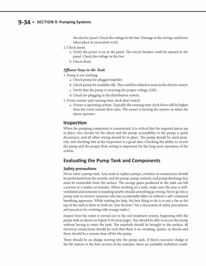
9-34 ■ SECTION 9:
the electric panel. Check the voltage in the line. Damage to the wiring could have taken place in excavation work.
2. Check panel.a. Verify the power is on in the panel. The circuit breaker could be opened in the
panel. Check the voltage in the line. b. Check floats.
Effluent Stays in the Tank1. Pump is not working.
a. Check pump for plugged impeller. b. Check pump for available tdh. This could be related to wear in the electric motor. c. Verify that the pump is receiving the proper voltage (220). d. Check for plugging in the distribution system.
2. Event counter and running time clock don’t match.a. Owner is operating system. Typically the running time clock flows will be higher
than the event counter flow rates. The owner is turning the system on when the alarm operates.
When the pumping component is constructed, it is critical that the required pieces are in place: two circuits for the alarm and the pump, accessibility to the pump, a quick disconnect, and all other wiring should be in place. The pump should be sized prop-erly, and checking this at the inspection is a good idea. Checking the ability to rewire the pump and the proper float setting is important for the long-term operation of the system.
Never enter a pump tank. Any work to replace pumps, switches or connections should be performed from the outside, and the pump, pump controls, and pump discharge line must be removable from the surface. The sewage gases produced in the tank can kill a person in a matter of minutes. When working on a tank, make sure the area is well-ventilated and someone is standing nearby should something go wrong. Never go into a pump tank to retrieve someone who has accidentally fallen in without a self-contained breathing apparatus. While waiting for help, the best thing to do is to put a fan at the top of the tank to blow in fresh air. (See Section 7 for a discussion of safety precautions and practices for working with sewage tanks.) Inspect how the water is moved out to the soil treatment system, beginning with the pump tank as shown in Figure 9.18 (next page). You should be able to access the pump without having to enter the tank. The manhole should be brought to the surface, all electrical connections should be such that there is no smoking, sparks, or shocks and there should be a remote shut-off for the pump. There should be no sludge moving into the pump tank. If there’s excessive sludge in the lift station or the first section of the trenches, there are probably turbulent condi-
SECTION 9: ■ 9-35
tions in the tank, resulting in poor settling. As discussed above, users of the system can often make changes to alleviate the turbulence. Adding a pump basin is another method to minimize solids transfer. A pump basin is a container sur-rounding the pump. The container lip becomes the pump intake adding solids storage to the pumptank. The floats or controls must be set to as-sure that they do not get stuck on the container edges. Check the pump tank to see that it’s watertight, and inspect its structural integrity just as you inspected the septic tank. Verify that the pump has adequate capacity, taking into consideration friction loss. This means that effluent leaves the tank at the rate indicated on the design. There should be a quick dis-connect setup. Make sure that there is no standing water in the piping.
All electrical devices and devices containing mercury must be removed and dis-posed of according to applicable regulations (MN Rules Chapter 7080.2500, Subp. 1(B). The pump tanks are abandoned similarly to other tanks as described in Section 7: Septic Tanks. All the components must be removed before backfilling. If the old floats were mercury floats, these must be handled as a hazardous material. Be careful that the mercury vial is not broken during the process. All the wiring should be removed; the conduit can be left buried but should be capped.
FIGURE 9.18