seismic performance of dual concentrically braced steel...
TRANSCRIPT
a
71rpee | Série III | n.º 11 | novembro de 2019
Seismic performance of dual concentrically braced steel frames accounting for joint behavior
Desempenho sísmico dos pórticos metálicos duais com contraventamentos centrados incluindo comportamento das juntas
Melaku Seyoum Lemma Carlos Rebelo
Luís Simões da Silva
AbstractBeam-to-column joints play an important role in the overall seismic behavior of steel frame structures, since the deformations in the panel zone of the beam-to-column joint region significantly affects the seismic behavior of steel joints. This paper aims to assess the seismic performance of dual concentrically braced steel frames (D-CBF) through static and incremental dynamic nonlinear analyses using different strategies to detailed modelling of the joints. A case study building with 6-storeys and 4 bays is used to illustrate the design of a D-CBF with different joint performance levels and to assess the influence of the joints. The frame studied is a perimeter seismic resistant system while the inner frames are designed for gravity loads only. The design and seismic performance of the joints is based on the pre-normative design recommendations achieved in the scope of the EQUALJOINTS project where different design procedures for beam-to-column joints are proposed in order to render different performance objectives. The study explores the effects of the joint models and provides recommendations for the design of such frames specifically accounting for the different joint typologies.
ResumoAs juntas viga-pilar desempenham um papel importante no comportamento sísmico global das estruturas em aço, uma vez que as deformações na zona do painel da alma da coluna afetam o comportamento estrutural. Este trabalho tem como objetivo avaliar o desempenho sísmico de pórticos metálicos duais com contraventamentos centrados através de análises não-lineares dinâmicas incrementais usando diferentes estratégias para modelação das juntas. Um caso de estudo constituído por um edifício de 6 pisos e 4 vãos com pórticos resistentes duais compostos por pórtico simples e vão com contraventamentos centrados é usado como exemplo para a análise e avaliação dos diferentes níveis de desempenho das ligações. O dimensionamento e o desempenho cíclico das ligações baseiam-se nas recomendações de projeto pré-normativas desenvolvidas no âmbito do projeto europeu EQUALJOINTS. As regras de dimensionamento desenvolvidas incluem procedimentos para diferentes objetivos de desempenho. O sistema estrutural sismorresistente é composto por um sistema de resistência sísmica no perímetro do edifício e vãos internos dimensionados somente para cargas gravíticas. São abordadas as recomendações para o projeto deste tipo de estruturas no que se refere às diferentes tipologias de ligações.
Keywords: Steel joints / Seismic performance / Stiffness / Dual frames Palavras-chave: Juntas viga-pilar metálicas / Desempenho sísmico / Rigidez // Pórticos duais
72
Seismic performance of dual concentrically braced steel frames accounting for joint behaviorMelaku Seyoum Lemma, Carlos Rebelo, Luís Simões da Silva
rpee | Série III | n.º 11 | novembro de 2019
Aviso legal
As opiniões manifestadas na Revista Portuguesa de Engenharia de Estruturas são da exclusiva responsabilidade dos seus autores.
Legal notice
The views expressed in the Portuguese Journal of Structural Engineering are the sole responsibility of the authors.
LEMMA, M.S. [et al.] – Seismic performance of dual concentrically braced steel frames accounting for joint behavior. Revista Portuguesa de Engenharia de Estruturas. Ed. LNEC. Série III. n.º 11. ISSN 2183-8488. (novembro 2019) 71-82.
Melaku Seyoum Lemma
PhD StudentISISE, University of CoimbraCoimbra, [email protected]
Carlos Rebelo
Associate ProfessorISISE, University of CoimbraCoimbra, [email protected]
Luís Simões da Silva
ProfessorISISE, University of CoimbraCoimbra, [email protected]
1 IntroductionIn the point of assembly where a beam is connected to a column, the term “connection” refers to the physical component which mechanically fastens the beam and column and it is concentrated at the location where the fastening action occurs. While the term “joint”, on the other hand, refers to the connection plus the corresponding zone of interaction between the connected members (i.e. the panel zone in the column web) [1].
Eurocode 3 part 1-8 [2] states that the effects of the behavior of the joints on the distribution of internal forces and moments within a structure, and on the overall deformations of the structure, may generally be neglected, but where such effects are significant (such as in the case of semi-continuous joints) they should be taken into account. It identifies three simplified joint models as simple, continuous, and semi-continuous. Furthermore, it gives correlations for the joint modelling type depending on the joint classification and method of global analysis as shown in Table 1 where joints are classified in terms of their rigidity and strength.
Table 1 Type of joint models according to EN 1993 1-8
Methodof global analysis
Classification of joints
ElasticNominally
PinnedRigid Semi-rigid
Rigid-plasticNominally
pinnedFull-strength Partial-strength
Elastic-plasticNominally
pinnedRigid and
full-strength
Semi-rigidand partial-strength
Semi-rigidand full-strength
Rigid andpartial-strength
Type of joint model
Simple Continuous Semi-continuous
Dissipative structures demand a good level of ductility in the joints as the global performance of steel structures in seismic scenario is highly influenced by the post-elastic behavior of the connections. Ductile joints are crucial in seismic resistant steel structures due to their role in absorbing and dissipating energy in addition to dampening vibrations.
An effort was made to assess the level of influence that semi-rigid joints have on different frame typologies in the scope of the EQUALJOINTS+ project [3]. Current modelling practices by practicing design engineers vastly implement a simple center line to center line model possibly incorporating end offsets and rigid ends. Researchers, on the other hand, implement explicit panel zone modelling methods of varying complexity such as the Scissors-type model, and the Krawinkler model [4], [5] via the use of springs and rigid elements.
73
Seismic performance of dual concentrically braced steel frames accounting for joint behaviorMelaku Seyoum Lemma, Carlos Rebelo, Luís Simões da Silva
rpee | Série III | n.º 11 | novembro de 2019
The pre-normative research project EQUALJOINTS [6] implemented an additional classification of joints termed “equal strength” – that ranges between full and partial strength connections. Accordingly, joints have been classified based on strength as either weak, equal or full strength, while the web panel is classified as either weak, balanced or strong. Publications from the project recommended a set of coefficients and ratios for the estimation of joint and connection stiffness and strength for prequalified joints. Furthermore, it considers the use of semi-rigid connections in seismic conditions. This paper experiments with different joint modelling procedures/ /techniques available and these stiffness values in order to assess the effect of different connection typologies on the global performance of a dual concentrically braced steel frame in case study. Firstly, the frame is analyzed and designed disregarding the joint dimensions. The frame’s performance is then assessed for both the simplified models and the refined ones using three extended stiffened end-plate connection typologies of varying connection strength and joint stiffness values. At last, design is repeated – this time – based on analysis results obtained from the refined models, and is compared against the initial design.
2 Case study
2.1 Building configuration
The case study building is a 6-storey office building with 4 bays in each principal direction. It has a typical storey height of 3.50 m and the total height of the building is 21 m. The width of the building is 24 m with each bay measuring 6 m. The seismic resistance of the building is provided by the perimeter frames. As a result, the inner bays in both directions are to be designed for gravity loads only. The
perimeter frame is composed of a moment resisting frames and a concentrically braced bay. An arrangement of these lateral force resisting systems was made such that the joints in three of the four perimeter bays are moment resisting while the last bay is hinged. The braced bay is situated at the centre of the three moment resisting bays. It is assumed that the vertical transport access facilities, such as stairs and elevators, are provided by an external independent structure.
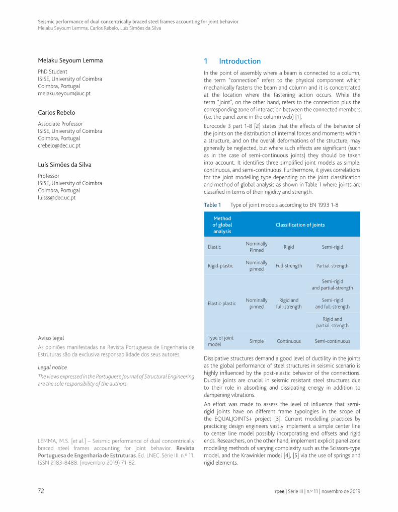
The seismic resistance scheme of the building and the tributary area for the perimeter frames in the Y-direction are depicted in Figure 1 (a). Figure 1 (b) shows an elevation view of the perimeter frame where the beams in the last bay are hinged at the ends, and the braces are assumed to be pinned.
A steel grade of S355 have been used for the beams and columns, while an S235 grade steel was used to model the braces. Owing to the planar and vertical regularity of the building, a 2D frame analysis was carried out to calculate the design actions. In doing so, tributary gravity loads are transferred to the perimeter 2D frames that are responsible of carrying the lateral forces in this building. The columns are assumed fixed at the base level and are continuous throughout the building height. The beams in the first three bays are assumed to be moment resisting while the one in the last bay is pinned at both ends (gravity beam). The diagonal bracings have been modelled as pin-pin connected at both ends, thus are modelled as bar elements taking axial forces only. The tributary seismic mass was lumped at nodes and rigid diaphragms were assumed to model the floor diaphragms. In addition, leaning columns were modelled and loaded with the seismic gravity loads that are not directly applied to the 2D frame model in order to capture the overall overturning effect. The analysis model was developed in SAP2000 [7].
Figure 1 (a) Plan view and tributary area, (b) Elevation view of the perimeter frame
(a) (b)
74
Seismic performance of dual concentrically braced steel frames accounting for joint behaviorMelaku Seyoum Lemma, Carlos Rebelo, Luís Simões da Silva
rpee | Série III | n.º 11 | novembro de 2019
2.2 Frame design
The frame was designed according to Eurocodes [8], [9] recommen-dations, however, disregarding the joint dimensions initially. Design checks were made for the design resistance of members in the two subsystems that constitute the D-CBF, i.e. the MRF and the CBF. In addition, a separate analysis was conducted to check the dual systems’ performance. AISC 341 [10] was used to check the contri-bution of each subsystem to the dual-frame. According to this code, it is necessary to guarantee that the MRF system has a minimum lateral strength equal to 25%. The braced parts of dual systems were designed to resist at least the 75% of the design lateral forces, as indicated by AISC 341. An approach adopted from [11] [12] was implemented where the MRF zones were not designed to resist the complementary 25% of the design forces, but to resist at least the 25% of the plastic lateral strength at each storey thus leading to the following design inequality:
( )+ −≥ × = × = × + × × αMRF DUAL DUAL CBFRd,i Rd,i Rd,i Rd,i pl pl iV . V V V N . N
. .1 1
0 25 0 3 cos0 75 0 75
The designed sections obtained are presented in Table 2.
Table 2 Design sections of the frame
Storey
Beam sections Column sections
Brace sectionsBraced bay Others AxesC1, C4 & C5
AxesC2 & C3
1 HEB500 IPE300 HEB220 HEM400 CHS 273 × 10
2 HEB500 IPE300 HEB220 HEM360 CHS 273 × 10
3 HEB500 IPE300 HEB200 HEM320 CHS 273 × 10
4 HEA450 IPE300 HEB200 HEM320 CHS 244.5 × 8
5 HEA450 IPE300 HEB180 HEB300 CHS 219.1 × 8
6 HEA400 IPE300 HEB180 HEB300 CHS 139.7 × 8
3 Non-linear analysisIn non-linear analysis, the mathematical model used for the usual elastic analysis is extended to include the strength of structural elements and their post-elastic behavior. The two methods, i.e., nonlinear static pushover analysis and nonlinear time-history dynamic analysis, are commonly used to evaluate the structural performance of buildings in the non-linear range.
3.1 Non-linear static (pushover) analysis
Pushover analysis is a non-linear static analysis carried out under conditions of constant gravity loads and monotonically increasing horizontal loads. The output of pushover analysis is a response curve of the structure expressed as a plot of base shear versus roof displacement. EN 1998-1 clause 4.3.3.4.2.2(1) requires the use of two lateral force distributions:
• a “uniform” pattern, based on mass proportional lateral forces, regardless of elevation (uniform response acceleration);
• a “modal” pattern, where the lateral forces are proportional to the fundamental mode of vibration weighted with the masses at each storey. This distribution corresponds to lateral forces determined as in the lateral force method.
In general, the “uniform” pattern leads to larger demand estimates at the lower storeys, while the “modal” pattern overestimates the demand for the upper storeys.
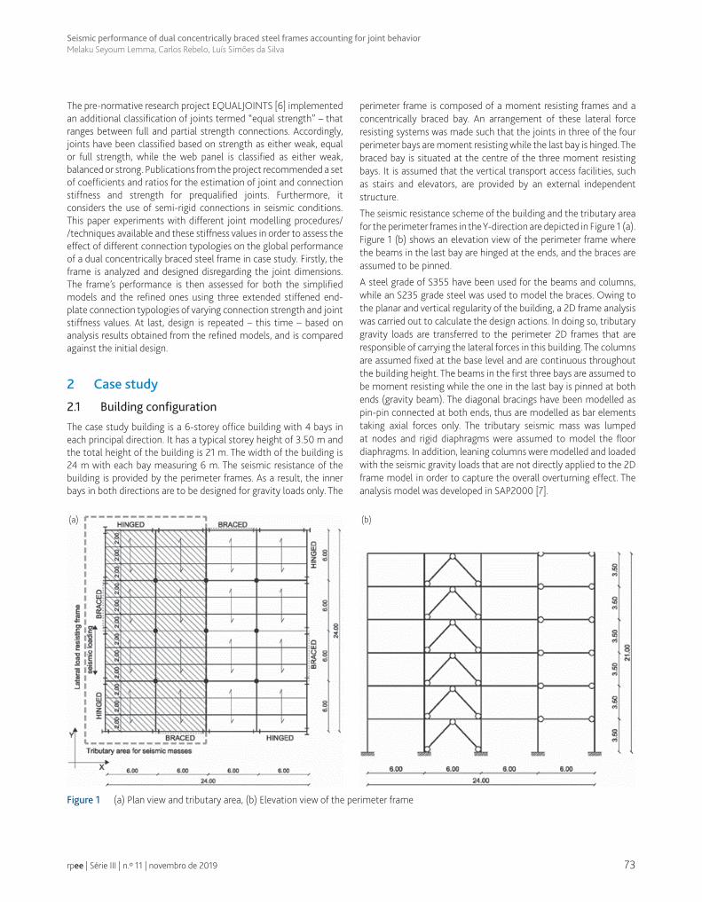
The formation of the plastic hinges is evaluated by the structural analysis program based on the plastic behaviour of the structural elements described in the form of a force – displacement or moment-rotation curves for each element. Annex B of EN 1998-3 [13] defines criteria for the acceptable damage state condition of the plastic hinges associated to three limit states: Damage Limitation (DL), Significant Damage (SD), and Near Collapse (NC) (see Figure 2). The parameters shown in Table 3, which are obtained from Tables B1, B2 and B3 of EN 1998-3 [13], were used to define Limit states for class 1 sections.
Figure 2 Generalized acceptance criteria – damage state conditions [14]
Table 3 Member deformation capacities at different limit states EN 1998-3 [13]
Limitstate
DriftBrace
ductilityin tension
Braceductility in
compression
Beamrotation
DL 0.75% 0.25 ∆t 0.25 ∆c 1θy
SD 2.50% 7.00 ∆t 4.00 ∆c 6 θy
NC 3% 9.00 ∆t 6.00 ∆c 8 θy
3.2 Non-linear incremental dynamic analysis (IDA)
Incremental Dynamic Analysis (IDA) is a nonlinear time-history dynamic analysis where one or various seismic inputs (ground motion records) are applied to a building model, each at different intensities – termed Intensity Measure “IM” – signifying different limit states/performance levels in order to evaluate the seismic performance of structures. These intensities are selected in such a way that it is possible to examine the structural behaviour from the

75
Seismic performance of dual concentrically braced steel frames accounting for joint behaviorMelaku Seyoum Lemma, Carlos Rebelo, Luís Simões da Silva
rpee | Série III | n.º 11 | novembro de 2019
initial elastic response to the inelastic response and finally to overall dynamic instability, which corresponds to collapse. IDA curves are the output of such analysis where the seismic intensity is reported against the structural response parameter (e.g. interstorey drift ratio) for each ground motion record.
In the current study, IDA analyses have been carried out for three increasing values of peak ground acceleration (PGA) corresponding to the three limit states: Damage limitation (DL), Severe Damage (SD) and Near Collapse (NC). The values of the multiplier of accelerograms are assumed equal to 0.59, 1 and 1.73 for DL, SD and NC, respectively. Record-to-record variability has been accounted for by considering 10 recorded accelerograms (see Table 4). These recorded accelerograms have been selected and scaled in such a way that the average value of the spectra of the accelerograms is approximately compatible with the linear elastic response spectrum of EN 1998-1 (see Figure 3), for soil type B and PGA of 0.35 g.
Table 4 Accelerograms and scaling factors used
No.Recorded
accelerogramScalingfactor
R1 Accumuli bevagna N-S 55.43
R2 ACHAIA Transversal 12.75
R3 AMATRICE E-W 9.81
R4 Brienza N-S 39.24
R5 Castelluccio Norcia N-S 15.21
R6 Castelsantangelosulnera E-W 5.89
R7 GEMONA L-T 11.97
R8 STURNO L-T 12.26
R9 TOLMEZZO Transversal 15.70
R10 Mirandola N-S 15.70
Figure 3 EC8 response spectrum compared to the avg. spectrum of the ground motion records
3.3 Modelling strategies
The frame was modelled in Seismostruct [15] and the following general modelling strategies were implemented.
3.3.1 Elementandmaterialmodel
As recommended in [16], columns, beams and diagonal bracings are modelled with Inelastic force based frame elements with fibre sections (InfrmFB). The Menegotto-Pinto (stl_mp) material available in Seismostruct is adopted representing the well-known uniaxial constitutive nonlinear hysteretic material model for steel. For each element, the cross section is meshed with at least 150 fibres and at least two of them across the thickness of the plate components (namely flange, web or walls). And at least 5 integration sections have been adopted for each member.
3.3.2 Leaningcolumnsandmasses
The gravity loads directly applied by the tributary area of loads acting on the planar frame do not reflect the actual amount of vertical forces producing overall overturning effects. Hence, in order to account for the influence given by the complement of vertical loads, a leaning column was modelled and loaded. Lumped mass elements are included in the nodes of the main frame representing the seismic mass of that particular frame on each storey.
3.3.3 Links
Link elements are used to model moment releases in the braces and beams in the last bay. They are also used in modelling in the leaning columns, as previously stated. Bi-linear (bi-kin) links are used to model the connection between the brace intercepted beams and supporting columns without the dissipative property. The bi-linear property includes the initial stiffness, the yielding moment and the post yield strain hardening rate taken as 1%. The strength and stiffness properties of the joints are calculated based on the values recommended in the EQUALJOINTS project (see Table 5). Zero-length M-θ springs accounting for the dissipative and degrading behaviour of the beams are placed at both ends of the beams outside of the braced bay. The hysteretic behaviour is modelled by links with the “smooth model” available in Seismostruct. The modelling parameter of the smooth model were calibrated using the software “Multi-Cal” [17] starting from the data of the experimental tests carried out in the framework of the EQUALJOINTS project.
3.3.4 Initialimperfectionofbraces
As recommended by [16] the brace members are subdivided into two. An initial imperfection of e0 = L/250 is applied to the CHS braces out of plane for class 1 sections of buckling curve ‘a’ in plastic analyses.
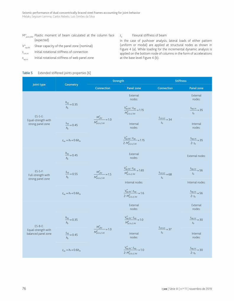
The definition of the terms and symbols used in Table 5 is presented as follows:
hrib Rib height
srib Rib width
hb Beam depth
zwp Web panel zone height
M nj,Rd Bending moment capacity of joint (nominal)
76
Seismic performance of dual concentrically braced steel frames accounting for joint behaviorMelaku Seyoum Lemma, Carlos Rebelo, Luís Simões da Silva
rpee | Série III | n.º 11 | novembro de 2019
Table 5 Extended stiffened joints properties [6]
Joint type GeometryStrength Stiffness
Connection Panel zone Connection Panel zone
ES-S-E:Equal-strength with strong panel zone
=rib
b
h.
h0 35
=nj,Rd
epl ,b ,cf ,Rd
M.
M1 0
Externalnodes:
=con ,ini
b
s
s34
Externalnodes:
⋅=
nwp ,Rd wp
epl ,b ,cf ,Rd
V z.
M1 15 =wp, ini
b
s
s35
=rib
b
s.
h0 45 Internal
nodes:Internalnodes:
= +bwp ribz h . h0 6⋅
=⋅
nwp ,Rd wp
epl ,b ,cf ,Rd
V z.
M1 15
2=
⋅wp, ini
b
s
s35
2
ES-S-F:Full-strength withstrong panel zone
=rib
b
h.
h0 45
=nj,Rd
epl ,b ,cf ,Rd
M.
M1 5
Externalnodes:
=con ,ini
b
s
s68
External nodes:
=rib
b
.h
s0 55
⋅=
nwp ,Rd wp
epl ,b ,cf ,Rd
V z.
M1 65 =wp, ini
b
s
s56
Internal nodes: Internal nodes:
= +bwp ribz h . h0 6⋅
=⋅
nwp ,Rd wp
epl ,b ,cf ,Rd
V z.
M1 6
2=
⋅wp, ini
b
s
s56
2
ES-B-E:Equal-strength with balanced panel zone
=nj,Rd
epl ,b ,cf ,Rd
M.
M1 0
Externalnodes:
=con ,ini
b
s
s37
Externalnodes:
=rib
b
h.
h0 35
⋅=
nwp ,Rd wp
epl ,b ,cf ,Rd
V z.
M1 0 =wp, ini
b
s
s30
=rib
b
s.
h0 45 Internal
nodes:Internalnodes:
= +bwp ribz h . h0 6⋅
=⋅
nwp ,Rd wp
epl ,b ,cf ,Rd
V z.
M1 0
2=
⋅wp, ini
b
s
s30
2
M epl,b,cf,Rd Plastic moment of beam calculated at the column face (expected)
V nwp,Rd Shear capacity of the panel zone (nominal)
scon,ini Initial rotational stiffness of connection
swp,ini Initial rotational stiffness of web panel zone
sb Flexural stiffness of beam
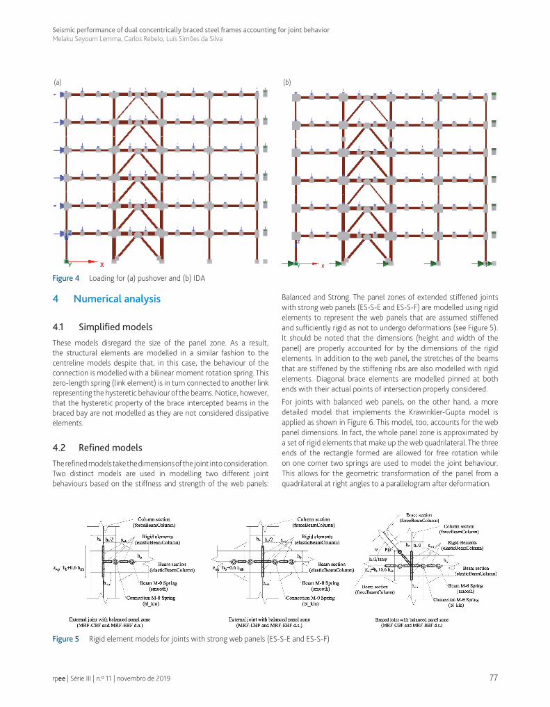
In the case of pushover analysis, lateral loads of either pattern (uniform or modal) are applied at structural nodes as shown in Figure 4 (a). While loading for the incremental dynamic analysis is applied on the bottom node of columns in the form of accelerations at the base level Figure 4 (b).
77
Seismic performance of dual concentrically braced steel frames accounting for joint behaviorMelaku Seyoum Lemma, Carlos Rebelo, Luís Simões da Silva
rpee | Série III | n.º 11 | novembro de 2019
4 Numerical analysis
4.1 Simplified models
These models disregard the size of the panel zone. As a result, the structural elements are modelled in a similar fashion to the centreline models despite that, in this case, the behaviour of the connection is modelled with a bilinear moment rotation spring. This zero-length spring (link element) is in turn connected to another link representing the hysteretic behaviour of the beams. Notice, however, that the hysteretic property of the brace intercepted beams in the braced bay are not modelled as they are not considered dissipative elements.
4.2 Refined models
The refined models take the dimensions of the joint into consideration. Two distinct models are used in modelling two different joint behaviours based on the stiffness and strength of the web panels:
Balanced and Strong. The panel zones of extended stiffened joints with strong web panels (ES-S-E and ES-S-F) are modelled using rigid elements to represent the web panels that are assumed stiffened and sufficiently rigid as not to undergo deformations (see Figure 5). It should be noted that the dimensions (height and width of the panel) are properly accounted for by the dimensions of the rigid elements. In addition to the web panel, the stretches of the beams that are stiffened by the stiffening ribs are also modelled with rigid elements. Diagonal brace elements are modelled pinned at both ends with their actual points of intersection properly considered.
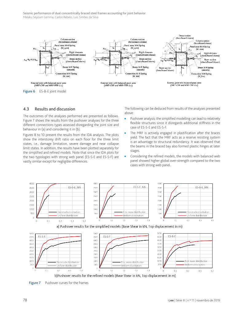
For joints with balanced web panels, on the other hand, a more detailed model that implements the Krawinkler-Gupta model is applied as shown in Figure 6. This model, too, accounts for the web panel dimensions. In fact, the whole panel zone is approximated by a set of rigid elements that make up the web quadrilateral. The three ends of the rectangle formed are allowed for free rotation while on one corner two springs are used to model the joint behaviour. This allows for the geometric transformation of the panel from a quadrilateral at right angles to a parallelogram after deformation.
Figure 4 Loading for (a) pushover and (b) IDA
Figure 5 Rigid element models for joints with strong web panels (ES-S-E and ES-S-F)
(a) (b)
78
Seismic performance of dual concentrically braced steel frames accounting for joint behaviorMelaku Seyoum Lemma, Carlos Rebelo, Luís Simões da Silva
rpee | Série III | n.º 11 | novembro de 2019
4.3 Results and discussion
The outcomes of the analyses performed are presented as follows. Figure 7 shows the results from the pushover analyses for the three different connections types assessed disregarding the joint size and behaviour in (a) and considering it in (b).
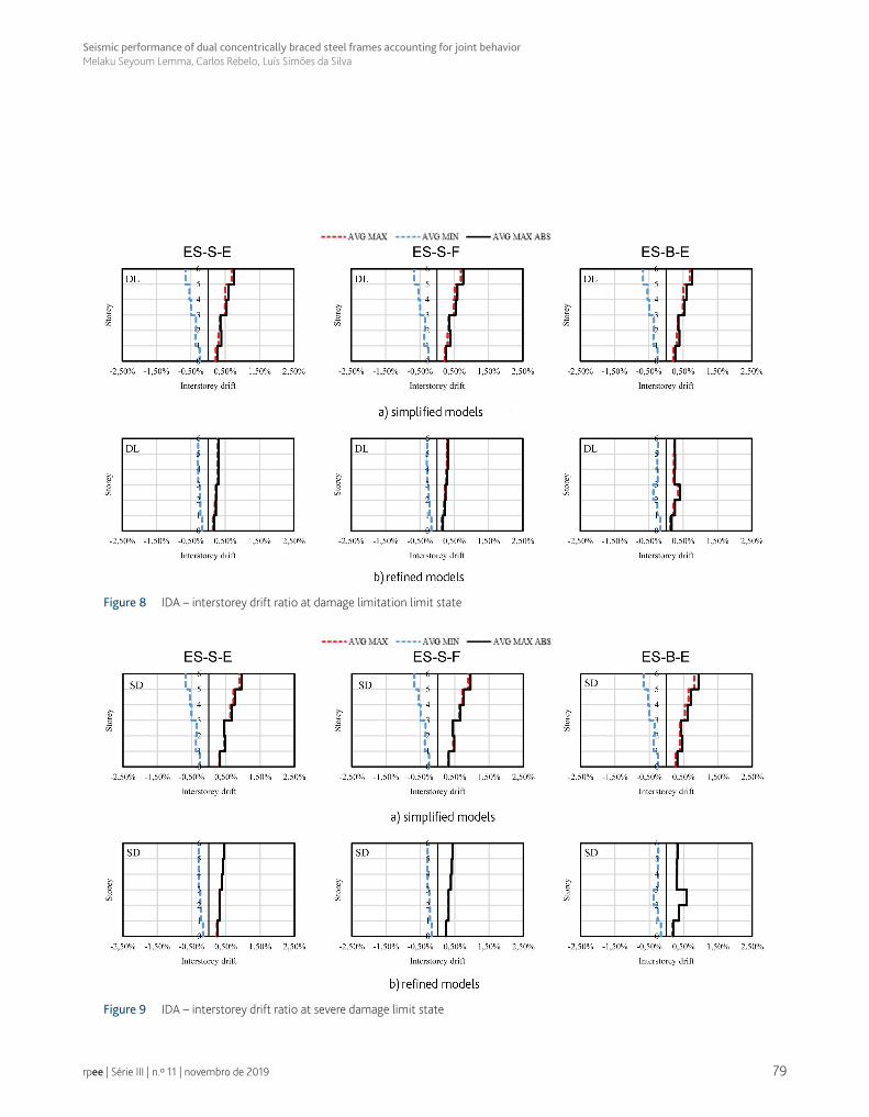
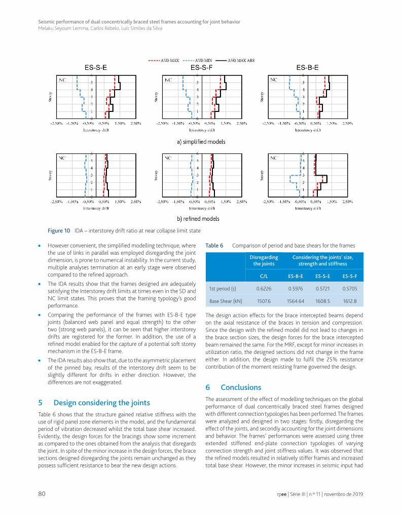
Figures 8 to 10 present the results from the IDA analysis. The plots show the interstorey drift ratio on each floor for the three limit states, i.e., damage limitation, severe damage and near collapse limit states. In addition, the results have been plotted separately for the simplified and refined models. Note that since the IDA plots for the two typologies with strong web panel (ES-S-E and ES-S-F) are vastly similar except for negligible differences.
The following can be deduced from results of the analyses presented above:
• Pushover analysis: the simplified modelling can lead to relatively flexible structures since it disregards additional stiffness in the case of ES-S-E and ES-S-F.
• The MRF is actively engaged in plastification after the braces yield. The fact that the MRF acts as a reserve resisting system is an advantage to structural redundancy. It was observed that the beams in the braced bay also formed plastic hinges at later stages.
• Considering the refined models, the models with balanced web panel showed higher global over-strength compared to the two cases with strong web panel.
Figure 6 ES-B-E joint model
Figure 7 Pushover curves for the frames
79
Seismic performance of dual concentrically braced steel frames accounting for joint behaviorMelaku Seyoum Lemma, Carlos Rebelo, Luís Simões da Silva
rpee | Série III | n.º 11 | novembro de 2019
Figure 8 IDA – interstorey drift ratio at damage limitation limit state
Figure 9 IDA – interstorey drift ratio at severe damage limit state
80
Seismic performance of dual concentrically braced steel frames accounting for joint behaviorMelaku Seyoum Lemma, Carlos Rebelo, Luís Simões da Silva
rpee | Série III | n.º 11 | novembro de 2019
• However convenient, the simplified modelling technique, where the use of links in parallel was employed disregarding the joint dimension, is prone to numerical instability. In the current study, multiple analyses termination at an early stage were observed compared to the refined approach.
• The IDA results show that the frames designed are adequately satisfying the Interstorey drift limits at times even in the SD and NC limit states. This proves that the framing typology’s good performance.
• Comparing the performance of the frames with ES-B-E type joints (balanced web panel and equal strength) to the other two (strong web panels), it can be seen that higher interstorey drifts are registered for the former. In addition, the use of a refined model enabled for the capture of a potential soft storey mechanism in the ES-B-E frame.
• The IDA results also show that, due to the asymmetric placement of the pinned bay, results of the interstorey drift seem to be slightly different for drifts in either direction. However, the differences are not exaggerated.
5 Design considering the jointsTable 6 shows that the structure gained relative stiffness with the use of rigid panel zone elements in the model, and the fundamental period of vibration decreased whilst the total base shear increased. Evidently, the design forces for the bracings show some increment as compared to the ones obtained from the analysis that disregards the joint. In spite of the minor increase in the design forces, the brace sections designed disregarding the joints remain unchanged as they possess sufficient resistance to bear the new design actions.
Figure 10 IDA – interstorey drift ratio at near collapse limit state
Table 6 Comparison of period and base shears for the frames
Disregarding the joints
Considering the joints’ size,strength and stiffness
C/L ES-B-E ES-S-E ES-S-F
1st period (s) 0.6226 0.5976 0.5721 0.5705
Base Shear (kN) 1507.6 1564.64 1608.5 1612.8
The design action effects for the brace intercepted beams depend on the axial resistance of the braces in tension and compression. Since the design with the refined model did not lead to changes in the brace section sizes, the design forces for the brace intercepted beam remained the same. For the MRF, except for minor increases in utilization ratio, the designed sections did not change in the frame either. In addition, the design made to fulfil the 25% resistance contribution of the moment resisting frame governed the design.
6 ConclusionsThe assessment of the effect of modelling techniques on the global performance of dual concentrically braced steel frames designed with different connection typologies has been performed. The frames were analyzed and designed in two stages: firstly, disregarding the effect of the joints, and secondly accounting for the joint dimensions and behavior. The frames’ performances were assessed using three extended stiffened end-plate connection typologies of varying connection strength and joint stiffness values. It was observed that the refined models resulted in relatively stiffer frames and increased total base shear. However, the minor increases in seismic input had

81
Seismic performance of dual concentrically braced steel frames accounting for joint behaviorMelaku Seyoum Lemma, Carlos Rebelo, Luís Simões da Silva
rpee | Série III | n.º 11 | novembro de 2019
negligible overall effect on the case study D-CBF. As the braced structure was the dominant lateral force resisting system, effects of changes in the stiffness of joints the structural behaviour were not significant. Pushover analyses proved the framing’s good seismic performance with the MRF acting as a reserve system compounding structural redundancy. The incremental dynamic analyses showed that the frames adequately satisfy the interstorey drift limits given in Eurocode 8. Furthermore, the refined modelling technique is recommended as it posed advantages such as identifying potential soft storey formation which were not observed with the simplified model.
AcknowledgementsThe authors acknowledge financial support from Research Fund for Coal and Steel (RFCS-754048/2017). This research was also financed by FEDER through COMPETE and by national funds through FCT within the scope of POCI-01-0145-FEDER-007633 and through the Regional Operational Programme CENTRO2020 within the scope of CENTRO-01-0145-FEDER-000006.
References
[1] ECCS – TC 13 Seismic Design, ECCS Manual 76 - Design of Steel Structures in Seismic Zones. Brussels, Belgium, 1994.
[2] European Committee for Standardization (CEN), – “Eurocode 3: Design of steel structures — Part 1-8: Design of joints, Incorporating Corrigenda Nos. 1 and 2”, 2005.
[3] Landolfo, R. et al. – “EQUALJOINTS+: Volume with pre-normative design recommendations for seismically qualified steel joints”, 2018.
[4] Krawinkler, H.; SAC, “FEMA 355c: The state-of-the-art report on system performance of moment resisting steel frames subjected to earthquake ground shaking”, Washington, D.C., 2000.
[5] Charney, F.A.; Downs, W.M. – “Modeling Procedures for Panel Zone Deformations in Moment Resisting Frames”, Connect. steel Struct. V. ESSC/AISC Work. Amsterdam, June 3-4., no. 3, pp. 121-130, 2004.
[6] Landolfo, R.; D’Aniello, M.; Augusto, H. – “EQUALJOINTS: European Pre-Qualified Steel Joints – Final Report”, European Commission, Brussels, Belgium, 2017.
[7] Computers and Structures Inc. – “SAP2000”, SAP2000. 2018.
[8] European Committee for Standardization (CEN) – “Eurocode 8: Design of structures for earthquake resistance – Part 1: General rules, seismic actions and rules for buildings”, Brussels, 2006.
[9] European Committee for Standardization (CEN) – “Eurocode 3: Part 1-1: General rules and rules for buildings”, 2002.
[10] American Institute of Steel Construction – ANSI/AISC 341-16, Seismic Provisions for Structural Steel Buildings, no. 1. 2016.
[11] Andre Tenchini, R.L.; Rebelo, C.; Luis Simöes, S.; D’Aniello, M. – “Seismic Performance of Dual Steel Concentric Braced Frames In Simple And Dual Configuration”, in Application of High Strength Steels in Seismic Resistant Structures, 2013, pp. 31-40.
[12] Dubina, D.; Stratan, A.; Vulcu, C.; Ciutina, A. – High strength steel in seismic resistant building frames - HSS SERF, vol. 7, no. 3. 2014.
[13] European Committee for Standardization (CEN) – “Eurocode 8: Design of structures for earthquake resistance – Part 3: Assessment and retrofitting of buildings”. European Committee for Standardization, Bruxelles, Brussels, 2004.
[14] Landolfo, R.; Mazzolani, F.; Dubina, D.; Simões da Silva, L.; D’Aniello, M. – Design of Steel Structures for Buildings in Seismic Areas: Eurocode 8: Design of Structures for Earthquake Resistance. Part 1: General Rules, Seismic Action and Rules for Buildings, 1st ed. Brussels, Belgium: ECCS – European Convention for Constructional Steelwork, 2017.
[15] Seismosoft – “SeismoStruct 2018 – A computer program for static and dynamic nonlinear analyses of framed structures”. 2018.
[16] D’Aniello, M.; La Manna Ambrosino, G.; Portioli, F.; Landolfo, R. – “Modelling aspects of the seismic response of steel concentric braced frames”, Steel Compos. Struct., vol. 15, no. 5, pp. 539-566, 2013.
[17] Chisari, C.; Francavilla, A.B.; Latour, M.; Piluso, V.; Rizzano, G.; Amadio, C. – “Critical issues in parameter calibration of cyclic models for steel members”, Eng. Struct., vol. 132, 2017.

82
Seismic performance of dual concentrically braced steel frames accounting for joint behaviorMelaku Seyoum Lemma, Carlos Rebelo, Luís Simões da Silva
rpee | Série III | n.º 11 | novembro de 2019