selected dht algorithms: chord and pastry - tut · selected dht algorithms: chord and pastry ... q...
TRANSCRIPT

Selected DHT algorithms: Chord and Pastry
Dmitri Moltchanov
Department of Communications EngineeringTampere University of Technology
October 24, 2014
Based on slides provided by R. Dunaytsev http://utopia.duth.gr/rdunayts/

Outline
1 Introduction
2 Chord
3 Pastry
4 Summary
5 Learning outcomes
Dmitri Moltchanov (TUT) ELT-53206, Lecture 4 October 24, 2014 2 / 34

Outline
1 Introduction
2 Chord
3 Pastry
4 Summary
5 Learning outcomes
Dmitri Moltchanov (TUT) ELT-53206, Lecture 4 October 24, 2014 3 / 34

Introduction
In P2P systems, cooperative peers self-organize themselves intooverlay networks and relay/store data for each other
The major challenge is how to achieve efficient resource search inthese large-scale distributed-storage networks
Overlay network
Physical network
Dmitri Moltchanov (TUT) ELT-53206, Lecture 4 October 24, 2014 4 / 34

Introduction (cont’d)
2 types of overlays :
UnstructuredStructured
Unstructured systems – do not impose any structure on theoverlay networks or loosely structured
E.g., Napster, Gnutella, Freenet, FastTrack, eDonkey2000, BitTorrentUsually resilient to peer dynamicsSupport complex search based on file metadataLow search efficiency, especially for unpopular files
Structured systems – impose particular structures on the overlaynetworks
E.g., Distributed Hash Tables (DHTs)The topology of the peer network is tightly controlledAny file can be located in a small number of overlay hops
Dmitri Moltchanov (TUT) ELT-53206, Lecture 4 October 24, 2014 5 / 34

Introduction (cont’d)
Search process in unstructured P2P systems
A
B
A B
CD
A
B
A
CB D
1. Query
2. Response
1. Query
2. Response
1a. Query
5. Get data
1. Query
2. Response
SuperpeersPeer Peer Tracker
ServerPeer Peer Peer
Napster Gnutella v0.4
FastTrack / Gnutella v0.6 BitTorrent
Swarm
3. Get data
3. Get data
3. G
et
da
ta
3. G
et
da
ta
1b
.
Qu
ery
2.
Qu
ery
3.
Re
sp
on
se
3. G
et
da
ta
4. Response
Dmitri Moltchanov (TUT) ELT-53206, Lecture 4 October 24, 2014 6 / 34

Introduction (cont’d)
Basic features of structured P2P overlays:
Structure – to accommodate participating nodes and data in theoverlayRouting algorithm – to locate nodes in the overlay and insert/retrievedata to/from themJoin/leave mechanisms – to enable self-organization and fault tolerance
Structures (aka geometries)
Structured overlays use a number of different geometries (rings, trees,hypercubes, tori, XOR, . . . )The primary goal is to enable the deterministic lookup (i.e., accessguarantees with certain time bounds)The performance is directly related to how nodes are arranged and howthe overlay structure is maintained when nodes arrive and leave
Dmitri Moltchanov (TUT) ELT-53206, Lecture 4 October 24, 2014 7 / 34

Introduction (cont’d)
Routing algorithms
They define how a target node is located in the overlay network
DHT-based routing algorithms work as follows:1 The node ID space is formed by applying a hashing function to node
IDs (e.g., MAC/IP addresses)2 A commonly used hashing function is SHA-1 (Secure Hash Algorithm
version 1)3 IDs for data items are created by applying the same hashing function
to them (e.g., filenames or keywords)4 Thus, the node IDs and data IDs fall into the same address space5 Data items are typically stored on the closest node with the node ID
greater than or equal to the data ID6 If the node with the closest ID does not store the data item, then it is
not available in the network7 Using this approach any existing data item can be found by any node
in the overlay
Dmitri Moltchanov (TUT) ELT-53206, Lecture 4 October 24, 2014 8 / 34

Introduction (cont’d)
Join/leave mechanisms
Usually, P2P systems are highly dynamic in nature (aka node churn)Hence, some mechanisms are needed to allow nodes to join or leave thesystem at any time with minimal impact to the functioning of theoverlay
Nodes join as follows:1 Get a unique ID for the node2 Position itself into the overlay structure based on the node ID and the
geometry3 Update the routing tables (both the joining node and all the affected
nodes)
Bootstrapping:As a rule, a new node contacts a bootstrapping server first and gets apartial list of existing nodesAnother common approach is to let nascent nodes know in advance anentry point into the network (e.g., a list of known nodes of the overlayor a list of non-public bootstrapping servers)
Dmitri Moltchanov (TUT) ELT-53206, Lecture 4 October 24, 2014 9 / 34

Introduction (cont’d)
Nodes leave as follows:1 When a node leaves or becomes unreachable, nodes that point to that
node are affected2 Their routing table entries will be stale and have to be updated3 A gracefully departing node notifies its neighbors about its departure4 Its neighbors then propagate these changes if needed5 However, a node may leave the system unexpectedly (e.g., due to
network failure or power outage)6 Under these circumstances, the node will not notify its neighbors7 Hence, the system must have some failure detection mechanism8 Failure detection is usually handled by keep-alive messages or periodic
checking
Dmitri Moltchanov (TUT) ELT-53206, Lecture 4 October 24, 2014 10 / 34

Introduction (cont’d)
In P2P file sharing systems, DHT just helps peers to find each other
Dmitri Moltchanov (TUT) ELT-53206, Lecture 4 October 24, 2014 11 / 34

Outline
1 Introduction
2 Chord
3 Pastry
4 Summary
5 Learning outcomes
Dmitri Moltchanov (TUT) ELT-53206, Lecture 4 October 24, 2014 12 / 34

Chord
Chord was proposed in 2001 by Ion Stoica, Robert Morris, DavidKarger, Frans Kaashoek, and Hari Balakrishnan, and was developedat MIT
See ”Chord: a scalable peer-to-peer lookup service for Internetapplications”
Chord uses consistent hashing and SHA-1 as a hash function to assigneach node (by hashing the node’s IP address) and each data item anm-bit ID, where m is a predefined system parameter
These IDs are arranged as a circle modulo 2m, from 0 to 2m − 1
Modulo arithmetic is a system of arithmetic for integers, wherenumbers ”wrap around” after they reach a certain value –the modulus
E.g., 7 + 7 + 7 ≡ 9 (mod 12)⇒ 9:00 PM or 21:00 (mod 24)
Dmitri Moltchanov (TUT) ELT-53206, Lecture 4 October 24, 2014 13 / 34

Chord (cont’d)
Data items are mapped to nodes whose ID is greater than or equal tothe ID of the data item (aka a key)
Due to consistent hashing, all nodes receive roughly the same numberof keys and can join/leave the system with minimal disruption
Thus, a node in a Chord circle with clockwise increasing IDs isresponsible for all keys that precede it counter-clockwise
Overlay network
Physical network
Dmitri Moltchanov (TUT) ELT-53206, Lecture 4 October 24, 2014 14 / 34

Chord (cont’d)
Each node has a successor and a predecessor
Since nodes may disappear from the network, each node recordsseveral nodes preceding it and following it
Each node also maintains information about (at most) m otherneighbors, called fingers, in a finger table
The i-th entry, i = 1, 2, . . . ,m, in the finger table of node N points tothe node whose ID is the smallest value bigger than or equal toN + 2i−1 (mod 2m) in the clock wise direction
N2 N4 N7
N12
N20
N43
N58 N60
N30N36N38N25
K61, K62, K63, K0, K1, K2i Target Successor
1 2 + 20 = 3 N4
2 2 + 21 = 4 N4
3 2 + 22 = 6 N7
4 2 + 23 = 10 N12
5 2 + 24 = 18 N20
6 2 + 25 = 34 N36
m = 6 (6-bit IDs)Keys (K) = [0, 1, …, 63]Nodes (N) = [0, 1, …, 63]
Finger table of node 2 (N2)
Dmitri Moltchanov (TUT) ELT-53206, Lecture 4 October 24, 2014 15 / 34

Chord (cont’d)
Chord routing algorithm:
The primary goal of the routing algorithm is to quickly locate thenode responsible for a particular key
Chord routing works as follows:1 A key lookup query is routed along the ID circle2 Upon receiving a lookup query, the node first checks if the lookup key
ID falls between this node ID + 1 and its successor ID3 If it does, then the node returns the successor ID as the destination
node and terminates the lookup service4 Otherwise, the node relays the lookup query to the node in its finger
table with ID closest to, but preceding, the lookup key ID5 The relaying process proceeds iteratively until the destination node is
found
Dmitri Moltchanov (TUT) ELT-53206, Lecture 4 October 24, 2014 16 / 34

Chord (cont’d)
m = 6 (i.e., modulo 2m = 64); 12 nodes; node 2 looks up key 45(1) N36 is the closest to key 45; (2) N43 immediately precedes key 45;(3) N58 is the first successor of key 45 on the circle
N2 N4 N7
N12
N20
N43
N58 N60
N30N36N38N25
Target Suc.
2 + 1 = 3 N4
2 + 2 = 4 N4
2 + 4 = 6 N7
2 + 8 = 10 N12
2 + 16 = 18 N20
2 + 32 = 34 N36
(1) Finger table of N2
(1)
Target Suc.
36 + 1 = 37 N38
36 + 2 = 38 N38
36 + 4 = 40 N43
36 + 8 = 44 N58
36 + 16 = 52 N58
36 + 32 ≡ 4 N4
(2) Finger table of N36
Target Suc.
43 + 1 = 44 N58
43 + 2 = 45 N58
43 + 4 = 47 N58
43 + 8 = 51 N58
43 + 16 = 59 N60
43 + 32 ≡ 11 N12
(3) Finger table of N43
(2)
(3)
45
K44 – K58
Dmitri Moltchanov (TUT) ELT-53206, Lecture 4 October 24, 2014 17 / 34
Chord (cont’d)
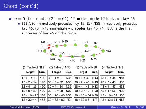
m = 6 (i.e., modulo 2m = 64); 12 nodes; node 12 looks up key 45(1) N30 immediately precedes key 45; (2) N38 immediately precedeskey 45; (3) N43 immediately precedes key 45; (4) N58 is the firstsuccessor of key 45 on the circle
N2 N4 N7
N12
N20
N43
N58 N60
N30N36N38N25
Target Suc.
12 + 1 = 13 N20
12 + 2 = 14 N20
12 + 4 = 16 N20
12 + 8 = 20 N20
12 + 16 = 28 N30
12 + 32 = 44 N58
(1) Table of N12
(1)
Target Suc.
30 + 1 = 31 N36
30 + 2 = 32 N36
30 + 4 = 34 N36
30 + 8 = 38 N38
30 + 16 = 46 N58
30 + 32 = 62 N2
(2) Table of N30
Target Suc.
38 + 1 = 39 N43
38 + 2 = 40 N43
38 + 4 = 42 N43
38 + 8 = 46 N58
38 + 16 = 54 N58
38 + 32 ≡ 6 N7
(3) Table of N38
(2)
45
Target Suc.
43 + 1 = 44 N58
43 + 2 = 45 N58
43 + 4 = 47 N58
43 + 8 = 51 N58
43 + 16 = 59 N60
43 + 32 ≡ 11 N12
(4) Table of N43
(3)
(4)
Dmitri Moltchanov (TUT) ELT-53206, Lecture 4 October 24, 2014 18 / 34

Chord (cont’d)
As a finger table stores at most m entries, its size is independent ofthe number of keys or nodes in the network
The Chord routing algorithm exploits the information stored in thefinger table of each node
A node forwards queries for a key K to the closest predecessor of K onthe ID circle according to its finger tableFor distant keys K , queries are routed over large distances on the IDcircle in a single hopThe closer the query gets to K , the more accurate the routinginformation of the intermediate nodes on the location of K becomes
Dmitri Moltchanov (TUT) ELT-53206, Lecture 4 October 24, 2014 19 / 34

Chord (cont’d)
It has been shown that the number of routing steps in Chord is at the
order of O(logN) , where N is the total number of nodes
According to the Change of Base Theorem, when we talk aboutlogarithmic growth, the base of the logarithm is not important:
loga N = C ∗ logb N, C = loga b, a, b > 0, a, b 6= 1
Queries on an unstructured P2P network tend to have lookupcomplexity of the order of O(N)
Dmitri Moltchanov (TUT) ELT-53206, Lecture 4 October 24, 2014 20 / 34

Chord (cont’d)
Chord join/leave mechanisms:
Nodes join as follows:1 The newly arrived node first uses consistent hashing to generate its ID2 It then contacts the bootstrapping server to lookup the successor ID3 This successor node becomes new node’s successor node4 The joining node is inserted into the overlay and takes on part of the
successor node’s load5 The new node uses a stabilization protocol to verify its finger table
To validate and update successor pointers as nodes join and leave thesystem, the stabilization protocol is executed periodically at thebackground of individual nodes
When a node detects a failure of a finger during a lookup, it choosesthe next best preceding node from its finger table
Dmitri Moltchanov (TUT) ELT-53206, Lecture 4 October 24, 2014 21 / 34

Outline
1 Introduction
2 Chord
3 Pastry
4 Summary
5 Learning outcomes
Dmitri Moltchanov (TUT) ELT-53206, Lecture 4 October 24, 2014 22 / 34

Pastry
Pastry was proposed in 2001 by Antony Rowstron and PeterDruschel, and was developed at Microsoft Research, Ltd., RiceUniversity, Purdue University, and University of Washington
See ”Pastry: scalable, decentralized object location and routing forlarge-scale peer-to-peer systems”The Pastry project: www.freepastry.org
Similar to Chord, its main goal is to create a completelydecentralized, structured P2P overlay in which objects can beefficiently located and lookup queries efficiently routed
Dmitri Moltchanov (TUT) ELT-53206, Lecture 4 October 24, 2014 23 / 34

Pastry (cont’d)
In Pastry, data items and nodes have unique 128-bit IDs, rangingfrom 0 to 2128 − 1
For the purposes of routing, these IDs are treated of as sequences ofdigits in base 2b
Typically, b = 4, so these digits are hexadecimal (HEX)
These IDs are arranged as a circle modulo 2128
The node IDs are randomly generated at node join, and uniformlydistributed in the ID space
Instead of organizing the ID space as a Chord-like circle, the Pastryrouting is based on numeric closeness of IDs
When forwarding a message to a destination key K , a node will choosethe node in its routing table with the longest prefix match
Dmitri Moltchanov (TUT) ELT-53206, Lecture 4 October 24, 2014 24 / 34

Pastry (cont’d)
Each node in Pastry maintains 3 tables:Routing tableLeaf setNeighborhood set
Routing table contains dlog2b Ne rows with 2b columns, where N isthe total number of Pastry nodes
The entries in row j refer to a node whose ID shares the present nodeID only in the first j digitsSimilar to Chord’s finger table, it stores links into the ID space
Leaf set is a set of l nodes with numerically closest IDs (1/2 largerand 1/2 smaller than the ID of the current node)
Like Chord’s successor list
Neighborhood set maintains information about nodes that areclose together in terms of network locality
E.g., number of IP hops, Round-Trip Time (RTT) values
Dmitri Moltchanov (TUT) ELT-53206, Lecture 4 October 24, 2014 25 / 34

Pastry (cont’d)
Pastry routing algorithm:
The primary goal of the routing algorithm is to quickly locate thenode responsible for a particular key
Pastry routing works as follows:1 Given a message with its key, the node first checks its leaf set2 If there is a node whose ID is closest to the key, the message is
forwarded directly to the node3 If the key is not covered by the leaf set, then the node checks the
routing table and the message is forwarded to a node that shares acommon prefix with the key by at least one more digit
4 This way, with log2b N steps, the message can reach its destinationnode
Thus, the number of routing steps in Pastry is at the order ofO(logN)
Dmitri Moltchanov (TUT) ELT-53206, Lecture 4 October 24, 2014 26 / 34

Pastry (cont’d)
b = 4; base 2b = 16; N = 10, 000 nodes; dlog16 10, 000e = 4 rows;node 63AB looks up key EB3E
From its routing table, node 63AB gets node E123, which shares1-digit common prefix with the keyNode E123 checks its routing table and gets node EB17, which shares2-digit common prefix with the keyNode EB17 then checks its routing table and gets node EB39, whichshares 3-digit common prefix with the keyFinally, node EB39 checks its leaf set and forwards the message directlyto node EB3E
63AB
(1) (2)
(3)
E123
EB17
EB39EB3E
2128
– 10
Dmitri Moltchanov (TUT) ELT-53206, Lecture 4 October 24, 2014 27 / 34
Pastry (cont’d)
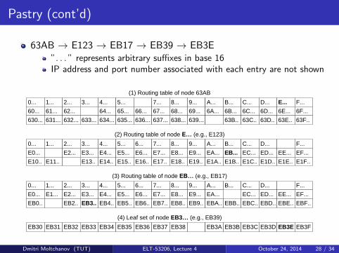
63AB → E123 → EB17 → EB39 → EB3E”. . . ” represents arbitrary suffixes in base 16IP address and port number associated with each entry are not shown
0...
(1) Routing table of node 63AB
60...
630...
1...
61...
631...
2...
62...
632...
3...
633...
4...
64...
634...
5...
65...
635...
66...
636...
7...
67...
637...
8...
68...
638...
9...
69...
639...
A...
6A...
B...
6B...
63B..
C...
6C...
63C..
D...
6D...
63D..
E...
6E...
63E..
F...
6F...
63F..
(2) Routing table of node E… (e.g., E123)
0...
E0...
E10..
1...
E11..
2...
E2...
3...
E3...
E13..
4...
E4...
E14..
5...
E5...
E15..
6...
E6...
E16..
7...
E7...
E17..
8...
E8...
E18..
9...
E9...
E19..
A...
EA...
E1A..
B...
EB...
E1B..
C...
EC...
E1C..
D...
ED...
E1D..
EE...
E1E..
F...
EF...
E1F..
(3) Routing table of node EB… (e.g., EB17)
0...
E0...
EB0..
1...
E1...
2...
E2...
EB2..
3...
E3...
EB3..
4...
E4...
EB4..
5...
E5...
EB5..
6...
E6...
EB6..
7...
E7...
EB7..
8...
E8...
EB8..
9...
E9...
EB9..
A...
EA...
EBA..
B...
EBB..
C...
EC...
EBC..
D...
ED...
EBD..
EE...
EBE..
F...
EF...
EBF..
(4) Leaf set of node EB3… (e.g., EB39)
EB30 EB31 EB32 EB33 EB34 EB35 EB36 EB37 EB38 EB3A EB3B EB3C EB3D EB3E EB3F
Dmitri Moltchanov (TUT) ELT-53206, Lecture 4 October 24, 2014 28 / 34
Pastry (cont’d)
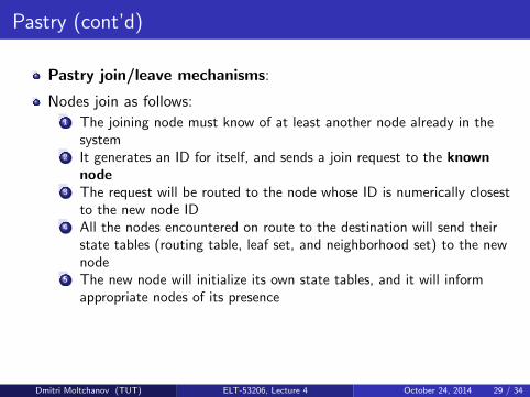
Pastry join/leave mechanisms:
Nodes join as follows:1 The joining node must know of at least another node already in the
system2 It generates an ID for itself, and sends a join request to the known
node3 The request will be routed to the node whose ID is numerically closest
to the new node ID4 All the nodes encountered on route to the destination will send their
state tables (routing table, leaf set, and neighborhood set) to the newnode
5 The new node will initialize its own state tables, and it will informappropriate nodes of its presence
Dmitri Moltchanov (TUT) ELT-53206, Lecture 4 October 24, 2014 29 / 34

Pastry (cont’d)
Nodes leave/failure as follows:1 Nodes in Pastry may fail or depart without any notice2 Routing table maintenance is handled by periodically exchanging
keep-alive messages among neighboring nodes3 If a node is unresponsive for a certain period, it is presumed failed4 All members of the failed node’s leaf set are then notified and they
update their leaf sets
With concurrent node failures, eventual message delivery isguaranteed unless l/2 or more nodes with adjacent IDs failsimultaneously
Parameter l is an even integer with typical value of 16
Dmitri Moltchanov (TUT) ELT-53206, Lecture 4 October 24, 2014 30 / 34

Outline
1 Introduction
2 Chord
3 Pastry
4 Summary
5 Learning outcomes
Dmitri Moltchanov (TUT) ELT-53206, Lecture 4 October 24, 2014 31 / 34
Summary
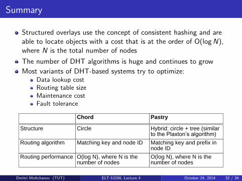
Structured overlays use the concept of consistent hashing and areable to locate objects with a cost that is at the order of O(logN),where N is the total number of nodes
The number of DHT algorithms is huge and continues to grow
Most variants of DHT-based systems try to optimize:Data lookup costRouting table sizeMaintenance costFault tolerance
Chord Pastry
Hybrid: circle + tree (similar to the Plaxton’s algorithm)
CircleStructure
Matching key and prefix in node ID
Matching key and node IDRouting algorithm
O(log N), where N is the number of nodes
O(log N), where N is the number of nodes
Routing performance
Dmitri Moltchanov (TUT) ELT-53206, Lecture 4 October 24, 2014 32 / 34

Outline
1 Introduction
2 Chord
3 Pastry
4 Summary
5 Learning outcomes
Dmitri Moltchanov (TUT) ELT-53206, Lecture 4 October 24, 2014 33 / 34
Learning Outcomes
Things to know:
Fundamentals of DHT algorithmsHow Chord worksHow Pastry works
Dmitri Moltchanov (TUT) ELT-53206, Lecture 4 October 24, 2014 34 / 34