ser-kits stirling class a passenger locomotive
TRANSCRIPT

SER-Kits A class instructions © Text and pictures Dan Garrett 2008 Page 1 of 47
SER-Kits
Stirling Class A passenger locomotive Instructions for assembly
Copyright text and model photos, Dan Garrett 1.5.2011
Table of contents
Page
Etched parts numbering 2
Section 1 Introduction, kit specification, Scale 7, tools needed 3 Section 2 Decisions to make: loco version, motor & gearbox, wheels- 4 Section 3 Starting Construction: the Bogie 7 Section 4 Constructing the Locomotive Chassis 8 Section 5 Fitting the Dummy Motion 15 Section 6 Making the coupling rods 17 Section 7 Getting the chassis running 18 Section 8 Further Detailing on the Chassis (brakes, sandboxes, reverser etc) 18 Section 9 Constructing the locomotive body 21 Section 10 Preparing the Resin Boiler 24 Section 11 Completing the loco body 26 Section 12 Detailing the Loco (castings) 27 Section 13 Cab fittings 29 Section 14 Constructing the tender – etched parts 31 Appendix A Wooden Sandwich Buffer Beams 37 Appendix B Loco running: troubleshooting 37 Appendix C Techniques 39 Appendix D Etched brake blocks – 4mm only 39 Appendix E Painting and Lining 40
Historical Notes 42
Photographic sources 46

SER-Kits A class instructions © Text and pictures Dan Garrett 2008 Page 2 of 47
A etch numbering Numbers may be suffixed HB for “High Boiler’ or Wainwright. Also S7 for Scale 7.
1. Main chassis, fold up 2. Rear chassis spacer 3. Cylinder rear head; 3F cylinder front head 4. Cylinder head laminate 1 5. Cylinder head laminates 2 6. Spare spacer washers 7. Front frame spacer 8. Axle-box bearing guides 9. Unused 10. Rear vacuum brake spindle brackets 11. Bogie sides; 11a spacing washers 12. Bogie top spacer 13. Bogie bottom spacer 14. Bogie ends 15. Spring hangers 16. Bogie angle irons 17. Bogie compensation beams 18. Coupling rods 19. Brake rods, 3-hole links and vacuum crank (2 separate boxes) 20. Reversing links 21. Balance weight: front drivers 22. Loco footplate 23. Valances 24. Loco drawplate 25. Smokebox wing plate 26. Front footplate over bogie; 26x footplate filler strips 27. Front buffer beam: rear plate 28. Front buffer beam: front plate; 28x: Buffer beam ‘box’ edge; 28y: front buffer beam drawhook
washer-plate 29. Ogee cylinder head cover plate; sides:29x 30. Cab side beading 31. Cab front (spectacle plate); 31x: four spectacle glass rims 32. Cab sides 33. Top of cab jointing plate 34. Front wheel splashers, sides and tops 35. Cab (tiny) splashers, sides 36. Cab (tiny) splashers, 37. Sandbox sides and tops (separate type) 38. Sandbox filler caps (laminate together) 39. Spare boiler band 40. Cab wheel-box sides 41. Cab wheel-box tops 42. Cab floor 43. brackets 44. Loco lamp irons 45. Top rear steps 46. Bottom rear steps 47. Front steps 48. Drain cock links, long or short 49. Vacuum cylinder trunnion 50. Tender sub-frame 51. Tender vacuum cylinder support

SER-Kits A class instructions © Text and pictures Dan Garrett 2008 Page 3 of 47
52. Tender axlebox guides 53. Vacuum brake crank 54. Tender guard irons 55. Tender frames 56. Brake spindle bearings 57. Tender footplate 58. Tender front drawbar 59. Tender rear drawbar 60. Frame beading x2 61. Rear drawbar washerplate 62. Tender steps 63. Loco-tender coupling 64. Water tank 65. Tank cross-piece 66. Water tank front 67. Bunker front 68. Shovelling plate 69. Coal door 70. Tender sandboxes, sides and tops 71. Side tender flares 72. Rear flare 73. Tank top toolbox 74. Tank top toolbox top 75. Tender lamp-irons 76. Water cock handles 77. Tender handrail tops 78. ‘Tiny’ cranks x4 79. Handbrake crank 80. Tender brake linkage (6 pieces) 81. 3-hole links – tender brake linkage 82. Fall plate 83. Headcode boards 84. Cab hand-wheels
Section 1: Introduction Kit specifications: • Etched 20 thou kit nickel-silver designed for easy slot and tab construction. • Etched coupling rods to be laminated together for scale thickness and strength. • Cast resin boiler (no rolling and soldering smokebox overlays!). • Various types of low-melt alloys are used in the kit. Vulnerable parts are cast in a tin-rich alloy which
will survive bending and re-bending. • The folded underframe enables all loco and tender axles to be sprung without buying additional parts. • Plunger pick-ups for the driving wheels. Parts supplied for self-assembly. Kit can take Slaters' pick-
ups if preferred. As 4-wheel pick-up is usually insufficient for good running the bogie is also designed for split-axle pick-up.
• Full motion and valve-gear (non-working for easier installation) • Full cab and external brake-gear detail. • Working sprung buffers. • Slaters’ cast n/s draw-hooks and couplings. • Etched headcode and special boards, lamp castings. Scale 7 : • Frame spacers are included to give an overall chassis width of 29mm.

SER-Kits A class instructions © Text and pictures Dan Garrett 2008 Page 4 of 47
Items needed to complete: • Wheels and axles – recommended: Slaters Driving Wheels Ref. 7872. Note that Stirling's crank boss
is between spokes, not in line. Bogie & tender wheels should be 3’8” but Slaters don’t make this diameter. For bogie wheels I chose Slaters Ref. 7845, which are 3’9” 10 spoke. This larger diameter plus the overscale flanges of O Finescale can cause fouling of the rear of the buffer beam on sharp curves. (See Para 9 of the Appendix ‘Getting it running’) Choice of tender wheels depends on whether you prefer to use internal or external bearings (see discussion in Section 2). For internal I use Slaters Ref. 7845 (3’9”) and for external Slaters 7843MF (3’7”). If you use the latter, you will need 6 Slaters' 0.1" top-hat brass-bearings for wagon wheels.
• Motor gearbox (read discussion in Section 2) and thin electrical wire • Flux and solder (Best if you have a couple with different melting points). • ‘Resin glue’ – i.e. 2-part epoxy resin glue (eg. 5-minute Araldite or Devcon) - and superglue. • Number plates, paint and lining. Warning
If you are new to locomotive kits, I strongly recommend that you read a book on locomotive modelling before starting this kit. Some notes on techniques are given in Appendix C but in general the instructions assume you understand basics such as sawing, filing, drilling, soldering, etc.
I do not recommend soldering the white-metal parts – some are made of a very low-melting point metal. In general, I recommend superglue and/or 2-part epoxy resin glue.
The model is capable of a very high degree of accurate detail. However, as a result, some of the work can be fiddly and time-consuming. It's up to you to decide how much you are able to do.
SER-Kits offers these instructions in good faith, b ut cannot be responsible for any problems arising. Modellers must use their own knowledge an d common-sense. Failure to follow the order of assembly may result in problems that are difficu lt to rectify at a later stage. Health and Safety • There are sharp edges on the etches, so handle carefully • When trimming the resin boiler, avoid breathing the resin dust (as with any fine dust) – wear a face-
mask. So far as I know the resin dust is not toxic, but why take the risk? • Don't heat the resin boiler – so do not solder near it after fixing. If you follow the instructions, the
resin boiler is fixed into place very late in assembly, after all soldering. Again, I'm not aware that hot resin poses a health risk, but better safe than sorry.
• Follow manufacturer's safety instructions for using solders, fluxes, epoxy resin adhesive and superglues – i.e generally avoid inhaling vapours and skin contact.
• The low-melt castings contain some lead. Dispose of filings and swarf safely and wash hands after. Do not eat while handling the castings (or solder, for that matter).
Tools To complete the kit, you need a reasonable modeller's toolkit with, eg. a small metal coping saw, tinsnips, fine-nosed pliers, small screwdrivers, a centre punch, a set of needle files, a flat (warding) file, tweezers, etc. A ruler and set-square are important for checking that everything is true. A glass-fibre 'pen' brush, a small steel bristle brush and an old toothbrush are valuable for cleaning up. A small 50 or 75mm jaw vice is fairly essential, along with a few small bulldog clips and clamps for holding things in place while soldering. A 12V modelling drill is well-worth the money, preferably with a pillar stand. You will break far fewer drills than using a hand-held drill. Although many of the necessary holes are etched, you will also need a variety of small drill bits, eg. 0.55, 0.6, 0.8, 0.9, 1.0, 1.2, 1.3, 1.4, 1.6, 1.8, 2.0, 2.2mm. Read up on soldering techniques if you're not very familiar with them. I used to use 25 and 40 watt soldering irons, and still do, but I've been converted to resistance soldering for some jobs. Certainly it can make jobs possible that used to require 3 hands.

SER-Kits A class instructions © Text and pictures Dan Garrett 2008 Page 5 of 47
Section 2: Decisions you need to make before starting Which version? – you choose
First read the historical notes at the end. The kit makes up into three main variants of the A: 1. Original batch: separate sandboxes, built up chimney, etc 2. Later batch: sandboxes integral with splashers, later cast chimney, etc 3. Wainwright high-boiler version
The kit can be supplied with either Smith’s non-automatic vacuum (phased out ca.1890) and the automatic vacuum brake: please state which when ordering. Design choices • Motor Position
The motion and valve gear are very clearly visible under the boiler and between front driving wheels and rear bogie wheels. They are even more visible in the Wainwright high-boiler version. Accordingly, dummy motion is supplied as standard and the kit is designed for the motor to drive the rear axle. The motor is intended to 'float' on its gearbox so that the driving axle can be sprung, and have sideways play.
However, if you choose to drive the front axle, then you will only be able to use some of the dummy motion, and the front of the firebox may need to be cut away. At the cab end you can gain a few millimetres space by removing part of the spectacle plate along the ½ etch line. The backhead casting is hollowed out.
• Motor type Various small motors with flywheel and gearbox will fit the loco in the intended 'upside-down', rear axle position. S & D Models GBL40 gearbox has the smallest gears, and if the top corners are sawn off is the least obtrusive – but it’s not always available. Supplied with a Mashima 1833 and flywheel, it performs very well. The Tower models and Branchlines 40:1 fold-up gear boxes work well with the Mashima 1833. The Branchlines gear-set with nylon worm is noticeably quieter. The Roxey fold-up gear-box is too wide for adequate side-play if you have tightish curves. There is a small ABC gearbox which will fit, and these are well regarded by those who can afford them.
The tender wheels
The kit allows them to be fitted in two ways: 1) following prototype practice, the cast axle-boxes are sprung and slide in guides - see Appendix A; 2) the conventional modeller's approach using a subframe with internal bearings, complete with springing. This method is probably slightly easier, but the non-prototype 'hornblocks' will be visible when the tender is viewed at an angle.
If you use internal bearings, then you should choose bogie type wheels (Slaters 7845, 3'9"). If you use external bearings, then you need to buy wheels with protruding axles. In the Slaters' catalogue, this means the Martin Finney type 7843MF (not the LSWR version), which is slightly too small in diameter at 3' 7". You will also need six Slaters wagon-type 'top-hat' bearings.
• Compromises: The motion & valve-gear for each cylinder are set closer together than in the prototype, in order to suit Fine-scale, and to clear the overscale bearings. Etched S7 parts will allow this to be rectified, replacing the cast motion plate as well as cylinder front and backs. The wheel splashers and cab wheel housings are wider because of the back-to-back measurements of Finescale. Modifying them for Scale Seven should be easy and there are often ½-etches as a guide. Just about everything else is as near to scale as is feasible.
• Various design choices are described at the appropriate point in the instructions.
• There seems to be no Ashford GA drawing available, though apparently there is one hidden from the world in a private collection. My drawing pulls together controversial sources, as discussed in the historical notes. The drawing was compared with broadside photos and some small corrections made, most noticeable the radius midway up the cab sides, which scales at 16”, more than the publicity drawing. From 2017, a revised etch will be supplied. If a second-hand A kit comes on the market, check with SER-Kits as to which etch you have. If it contains printed instructions then it’s

SER-Kits A class instructions © Text and pictures Dan Garrett 2008 Page 6 of 47
likely the kit has the original etch. These instructions offer suggestions as to how the (few) etch errors on the original can be corrected.
IMPORTANT NOTES:
• Etched parts are numbered – see list above. Where alternatives are needed to cover the Wainwright/SE&CR high boiler version the numbers are followed by the letters HB.
• The instructions refer to pins – dressmakers' pins requiring a 0.65mm clearance hole.
• In these instructions the word 'drawings' refers to the scale plans and elevations of the locomotives. These are supplied as part of the kit or can be purchased separately. The word 'diagrams' refers to non-scale sketches embedded in the text.

SER-Kits A class instructions © Text and pictures Dan Garrett 2008 Page 7 of 47
Section 3: Starting Construction: the Bogie
1. The bogie is intended to allow electrical pick up from the
wheels, using the split axle/split frame method. The principle is shown in this diagram. One horizontal spacer and one end is soldered to each side. The two assemblies are separated by a styrene spacer and joined with 4 8BA bolts. The etched holes are arranged so that one spacer does not touch the bolts, while the bolt heads are kept from the spacer by another thin styrene sheet.
2. Etched compensating beams (Parts No.16) are supplied for locos prior to mid 1890s (See historical notes.)
3. Punch rivets in sides 11, fold ends 14, and solder each end to one side, locating with a bearing (NB: the bearings protrude on the outside)
4. Solder the remaining two bearings. BUT FIRST NOTE: They will protrude too much and should be filed down ½ mm. or alternatively, use washers 11a.
5. Cut out three pieces of styrene sheet, one of 60 thou, one of 20 thou and one of 10 thou to these dimensions:
6. Laminate the 60 & 20 thou pieces, and drill these and the 10 thou piece as shown.
7. Make a trial assembly of the bogie, with the 80 thou styrene laminate between the two spacers, and the 10 thou styrene underneath. Trial the axles (or better, lengths of 3/16 rod) and make any necessary bearing adjustments.
8. Then try the electrical (dis-)continuity with a multimeter or battery & bulb, if necessary slightly adjusting the positioning of the two halves and re-assembling one bolt at a time (be sure the non-joining corners aren’t touching and giving false readings).
9. When you are satisfied with the electrical and mechanical fit, glue the corners as in the diagram, but it’s probably sensible to solder the spring-hangers before this. See Instructions 13 & 14 below.
10. Next the wheels and axles: Split the axle by your preferred method. Here is one well-known method: First drill two small holes, say 1mm, right through each axles. Second, with a coping saw, cut a slot between the two holes and cut across the axle down to one of the holes. Fill the right-angled slot with resin glue and allow to set. Finally, cut across the other side of the axle down to the second hole to create the z-shaped break, and fill the second slot with resin glue. Be careful when tightening the wheel screws not to stress the glue.
11. If you are using plastic-centred wheels, e.g Slaters’, you need to short across between tyre and boss. On the rear of each wheel, carefully cut a thin slot with a fine saw or (very carefully) with a slitting disc, from tyre to boss down one spoke. With a hot iron, and without dwelling (or you’ll melt the plastic) solder a piece of thin wire between boss and tyre. Then run a file over the back of the wheel to remove any excess solder and wire, so that the back-to-back dimension will not be affected. It may be possible to achieve the same result with electrical conducting paint. I haven’t tried it myself.

SER-Kits A class instructions © Text and pictures Dan Garrett 2008 Page 8 of 47
12. Punch out the rivets in the spring hangers 15 and angle-iron detail 16. The spring-hangers are to be folded and curved as in the diagram, but for fine-scale (with its lesser back-to-back clearance) they will foul the rear of the bogie wheels. The best remedy is to re-drill the holes 1.5mm below the existing holes, and cut down the tops. The easier remedy is to cut off the bottom rivet.
13. Solder the spring hangers 15 in place using thin rod to locate them. Don’t dwell or you may melt the styrene sheet and loosen the resin glue.
14. The angle iron details 16 should be glued to the front of the chassis as in the elevation drawing, but make sure that they don’t electrically short between front & side.
15. The long 6BA bolt is threaded up through the bogie with a nylon bush on the top to ensure electrical separation. The long spring is held on the bolt by a nut, and the whole assembly can be screwed into a 6BA nut soldered into the chassis (see later).
16. For locos running up to the mid-1890s, there were probably compensating beams between the springs. (Certainly they were on Nos.159 & 179.) These are represented by Parts 17. Pop the large centre rivet, and also pop rivets at the ends of the comp. beam. Solder across bottoms of spring hangers, to cover the middle hole.
17. For locos running after the mid-1890s, glue the stabiliser bracket (rubbing plate) casting into the middle hole, after drilling into the styrene.
18. There are small tags on the bogie spacers for electrical leads. These tags are not shown in the photo which is from the original etch.
Section 4: Constructing the Locomotive Chassis 19. Start with the fold-up frames and spacers etch
(Parts 1 & 2 ). Remove the parts etched within the holes (e.g brake hangers and brake rods, lamp irons, etc. and keep the bits safely for later on.) Before folding, some punching and drilling is needed, depending on the preferred construction choices. So before doing anything, please read the following and refer to Diagram 1 over.
20. For S7 , there is an alternative Part 2 and an alternative for the bogie bearing + smokebox crossbearer. Also a motion plate to replace the F/S casting. There wasn’t room for an S7 firebox front, and I suggest cutting this off, and snipping the motor hole crosspieces. When the spacers are in place, solder spare etch joining strips to reinforce the hole.
21. Note: • The brass Slaters axle-boxes slide up and down in slots, and are prevented from falling out by
keeper plates. The keeper plates can be folded up later and if you choose this method, then punch rivets at each keeper plate – 4 lots of 4. It’s probably better to make removable keeper plates. In this case, drill the rivet holes 0.6mm, then cut off and keep the keeper plates safe. Later you can fix them in place with pins. (Or your own 16BA nuts & bolts).

SER-Kits A class instructions © Text and pictures Dan Garrett 2008 Page 9 of 47
• Before folding the chassis you will need to open out the half-etch pick-up holes P. The etched diameter is accurate for the nylon bushes supplied, but will probably not suit other manufacturers’ pick-ups. The holes, E in the diagram, are for electrical leads.
• Note that the loco spring castings will eventually be fixed by pins through the holes marked S.
• BRAKES: these will be fixed to 12BA brass bolts soldered into the holes B.
DIAGRAM 1
22. Pick-ups: drill the ½ etch holes P and open out to the etch diameter. The nylon top-hat bushes are to
be a push-fit in these holes – see Instruction 33.
23. Sandpipes: holes are etched in the footplate and the sandpipes can be soldered there. However, when constructing the loco, I decided to solder them into the frames – it makes dismantling the finished loco easier. It also means you can solder the little stay between motion plate and each sandpipe. If you want to use this the method, then drill a 1.3 mm hole (marked SP in Diagram 1).
24. The springing units. Each axle-box is intended to slide up and down, guided by the underframe slots in the frames and by the axle-box guides 8. The axle-boxes are fitted with the lip facing inwards to give some sideways axle play when the loco rounds curves. The vertical movement of the axle-boxes is controlled by phosphor-bronze coil springs and restricted by an adjustable 12BA bolt. The top photo shows what you're aiming for:
25. When you're sure you understand the intended
construction method, proceed as follows: Remove the axle-box guides 8. Prepare the holes in the tags above each axle-box slot as follows: If possible, cut a thread with a 12BA tap. If you don't possess a tap, improvise one as follows. Take one of the steel 12 BA bolts and file the last couple of millimetres almost to a point. Then drill a 1.3mm hole in a small block of wood to support the tag while you use a screwdriver to drive the tapered bolt into the hole in the tag, turning it as you go to cut a thread. (See photo:)
26. Alternatively, cut off the tag, file down one of the flats on a 12BA nut (not supplied) and solder just above where the tag was – but do this later, after soldering the axle-box guides into place.
27. Punch firebox rivets in the axle-box guides and ash-pan sides (Parts 9). Fold up the tags above the axle-box slots and strengthen with a fillet of solder.
28. Then refer to the diagram below to see what you're aiming for as you carry out the next steps. Fold the frames down from the spacers. Fold the firebox front down, backwards, and down again to match the profile of the firebox bottom & ashpan. Fold down and back the rear part of the smokebox cross-

SER-Kits A class instructions © Text and pictures Dan Garrett 2008 Page 10 of 47
strengthener which will hold the bogie pivot.
29. Fold and solder the rear spacer (2) into position.
30. Now refer to Diagram 2 for the next stages. Clamp one axle-box guide 8 and one ashpan etch – 9 or 9HB - inside the side-frame. Make sure the rivets project outwards! The guides can be located with temporary pins in the loco-spring holes S and a cocktail stick in the brake hanger hole. Check the alignment so that the axle-boxes slide up and down without binding. Fix the guides in place with a couple of dabs of solder, and when satisfied that the axle-boxes slide easily and correctly, finish soldering the guides.
31. Repeat for the other side, and then complete the underframe 'box', by soldering the firebox front to the sides as follows. Fold the rear spacer 2 and solder in place.
32. Solder each cylinder head 5 to the figure of 8 shaped piece 4 and to the cylinder spacer 3. Locate the parts with matchsticks. (Yes, I know they look very odd shapes! That’s because Fine-scale has frames too narrow to hold scale cylinders. Look at the Scale7 parts for the true shape. However, once the motion and boiler are in place, you can’t tell that they’re not circular as they should be.) Solder the cylinder head spacer in place. In 2017, the etch was revised to include a front cylinder head 3F to go in slots not shown in above diagrams.

SER-Kits A class instructions © Text and pictures Dan Garrett 2008 Page 11 of 47
33. Just for reference, the photo shows the slide-bar holders and valve guides placed in position. But don’t fit them yet! You will find some little washers (Part No. 6) on the etch. These were intended as packing between the cylinder head and and the slide-bar holders, but they didn’t seem to be necessary when I made up my model. But remember them in case you need them later when you add your motion.
34. Solder the front frame spacer 7 as in this photo. NOTE that on the prototype, the frames did not taper. You’re welcome to follow James Stirling, but don’t blame me if your loco won’t go round your curves! However, if you’re worried about looks, when you assemble the body you’ll find the frames are straight where they can be seen from above. The photo also shows how I’ve added slightly curved pieces from scrap etch to represent the cylinder block casting. Only necessary if you’re fussy!
35. Solder the vacuum brake spindle brackets 10 outside the rear of the frames. (Diagram with Note 20) It's stronger to drill 0.65mm through the three half-etch rivet holes rather than punch them, and solder pins through them and the trunnions.
36. Either tap 12BA the holes B, or drill them out to allow a 12BA brass bolt to be threaded through from the inside. Solder the bolt head to the frame. At a later stage, the brakes will be hung from these bolts.
37. The loco vacuum cylinder is under the cab, but barely visible and can well be omitted. If you want to fit one, a support trunnion is supplied – 49. It should butt up against the rear spacer 2 as in the cab side elevation. A half cylinder can be rolled from a piece of spare etch.
38. Make a pivot for the vertical reversing link as follows: Cut a 3mm piece of 1/16" rod and solder into the hole in the RH frame which is approximately 22 mm ahead of the rear axle and just below the top of the frame. (Refer to the loco drawing, and see photo on P.17)
39. Solder pins into the holes S either side of the axle-box slots – 8 in all. Cut them to 3mm. In the final stages of assembly, the cast driving wheel springs will be hung from these pins.
40. At this stage, it's worth making a trial assembly of the bearings, wheels and axles, as described in the next few instructions.
41. Check that the axle-boxes slide easily in their guides - neither binding, nor having too much play. If filing is needed, file both sides of the guides evenly. Check that the outer (squared) sides of the axle-boxes fit smoothly between the frame slots. Again, any filing should be done equally on both edges. You may need to mark the top of each axle-box, as they can sometimes be slightly rectangular rather than truly square.
42. Remove the top of each of the 4 bearings as shown, to form a seating for the coil spring. I find a spherical burr useful. The lips on the rear bearings may need reducing to make room for the gearbox. Finally, insert each axle-box and gently bend the keeper plates into position. Screw in the 12 BA adjusting bolts, but don't bother with the coil springs at this stage. See the photo with Instruction 12. (Ideally, turn the bolts into grub screws by removing the head and sawing a cross-slot)
43. Make up the four plunger pick-ups as follows: Push the top-hat nylon bushes into the holes in the underframe (holes labelled P in Diagram 1) with the hat-brim inside.

SER-Kits A class instructions © Text and pictures Dan Garrett 2008 Page 12 of 47
44. Cut 4 strips of scrap brass etch about 7mm x 3mm; 4 x 6mm lengths of 3/32" brass tube; and 4 x 6mm lengths of 1/8" brass tube. Then for each pick-up: Insert the 3/32" tube into the 1/8" tube. Using higher melting point solder, solder one of the strips over the end of the double tube to form a closer and electrical tag and also to hold the two tubes together.
45. Slightly taper the 1/8" tube until it just enters the nylon bush without force. Then push it in a couple of millimetres or so into the nylon bush. Trim the bush so it and the tube protrude about 1mm on the outside of the frame, and hold with superglue. The photo (of a Stirling O) shows what’s intended. Later on, use lower melting point solder with a hot iron to attach the leads.
For each plunger, round the end of a piece of 1/16" rod almost to a point, and cut off a 3.5mm length. (TIP: To taper, turn the rod in a drill, and hold a file against it at about 45o.) Repeat until you have 4 plungers. If you can use the edge of a file to create the shape in the diagram, so much the better, as it will centre the plunger on the spring. Clean off the sawn ends, so that the plungers slide easily in the tubes with the tapered end outwards. In the final assembly stages you should complete the pick-ups by snipping off lengths of the fine 1.5mm diam. spring, but for the moment put the plungers and spring carefully aside where they will not be lost.
46. READY FOR A TRIAL RUN by hand: Cut 4 driving wheel springs 6 mm long from the 2.4 mm diameter phosphor-bronze spring. With tweezers, thread over the adjuster bolts to bear on the axle-boxes. NOTE: the final springing adjustments must be made later since they require the weight of the completed loco body.
47. Fix the wheel sets and attach the bogie as described earlier. Check that each axle turns freely in it its axle-box. If necessary run a 3/16" drill through the axle-box hole.
48. Push the underframe round your sharpest curve, and check the side-play of each axle. . The idea is that the bogie slews the chassis across the curve. If it were to be slotted (as in early tinplate locos) the bogie wheels would foul the frames and cause a short circuit. By leaving side-play on the middle axle, the bogie wheels should just clear the frame. I have one or two 4-foot (1.2m) curves and have to allow side play on the rear axle as well. The advantage of this method is that the front and buffers do not overhang the curve in an ungainly way. If you have less sharp curves, there are full and ½ etch packing washers on the etch to reduce side-play.
49. Trial the motor and gearbox on the rear axle. Note that it's intended that the motor and gearbox should be 'upside down' – i.e the worm is below the axle, and the motor is fed upwards through the firebox until it's diagonal. This arrangement enables a flywheel to be used, but it will need to be removed during fitting. There is room under the loco for a DCC decoder. The frame-spacers may need reducing or removing. Some gearboxes (e.g the MSC, Roxey and Home of O Gauge) may require the lips on the axle bearings to be reduced to make room for them. When you're satisfied, make a note of the washers, and remove wheels, motor and gearbox.
50. Now thread the electrical leads through the various holes in the chassis and solder. Note that the bogie leads should be soldered to the side-frames, then taken up into the chassis, leaving some slack and fed out through holes under the smokebox saddle, along the top of the frames under the footplate where they can’t be seen, and back in, just head of the front driving axle.
51. Cut 4 pick-up plunger springs 4mm long from the length of 1.5mm fine spring.
52. Take off each wheel in turn, insert the plungers & springs. It can be helpful to hold the plunger in with a knife-blade or sticky tape until the wheel prevents it pinging out and inevitably getting lost…
TIP: If the wheels seem to turn too stiffly, you may need to reduce the length of the plunger springs. For the loco to run well, there's a fine balance between too much pressure and the need for the pick-ups to remain in contact with those wheelsets which have sideways play.
53. Loosen the worm wheel on the rear axle, and try the loco on the test track. All being well, the motor will turn happily. You can then tighten the worm wheel grub screw and see how she goes.

SER-Kits A class instructions © Text and pictures Dan Garrett 2008 Page 13 of 47
54. At this stage, or later before painting, fit balance weights 21 for the front driving wheels to cover three gaps between spokes. Glue in place as in the side elevation drawing. If you make both wheels identical, they will be correct when fitted, since the balance weight trails the crank on the RH side and leads on the LH. Fill behind the segments with Milliput or similar. When fitting the wheels, I assume the weights should be opposite the internal cranks, but I’m open to correction on this. There appear to be no balance weights on the rear drivers.

SER-Kits A class instructions © Text and pictures Dan Garrett 2008 Page 14 of 47

SER-Kits A class instructions © Text and pictures Dan Garrett 2008 Page 15 of 47
Section 5: Fitting the Dummy Motion
1. From now on, white-metal additions may make some soldering problematic, so be sure you've carried out all the steps described in Section 3.
2. Refer to the motion and valve-gear drawing as necessary to identify parts. Each part should be cleaned up before assembly by removing 'flash' and the remains of casting sprues.
3. Glue the Valve Spindles 5 & 6 into the holes marked Y on the above diagram. NOTE that the short spindle goes in the right-hand hole when viewed from the rear of the loco.
4. Assemble the Slide Bars (Castings No. 7): The Slide Bar Holder (Casting 4) has a spigot one side which will fit into the hole in the cylinder rear. (X to X in the diagrams) The other side has a representation of a packing gland with hole for the piston rod. Glue 2 plain slide bars and 2 with oil-pots into the holes in the square slide bar holder, making sure the bars with oil-pots are on top. (NOTE: I find it easiest to clamp the slide bar holder in a horizontal position and glue the bars in the vertical.) Repeat for the other set of slide bars.
5. While the glue is setting, prepare the Motion Plate (Casting 9). First, remove the four lower ‘tags’ representing angle iron. (They are for the O and R locos which have deeper frames). Next drill holes in the top and bottom brackets as shown in the diagram and photo. The same holes are labelled 'a' and 'b' in the scale drawing of the motion. Holes in the top brackets are for the top spigots in the expansion links/cranks (see later) and should be 1 mm diameter. Holes in the bottom brackets should be 1.6mm for the weigh shaft (see later). Also, clear out the 8 holes for the slide bars with a 1.5mm drill.
6. Note for S7 modellers: there is an etched replacement motion plate, but you will have to devise your own brackets.
7. Take the Cross-heads (Casting 8) and drill through with a 1.6mm drill where shown in the photo. Cut down one of the piston rods (the rod sticking out of the cross-head) to 5mm and the other to 14 mm.
8. Slide the cross-head with the short piston rod between the bars on the right-hand side of the engine (looking forward) until the piston rod fits into the hole in the packing gland. This complete assembly can be seen right way up in the above photo. Slide the cross-head with the long piston rod into the other bars.
9. At this stage, make a trial fit of the whole cylinder and slide bar assembly. Without gluing, fit the motion plate to the 8 slide bars with its brackets pointing towards the slide bar holders. and fit the slide-bar holders into the corresponding holes in the rear of the cylinders (X to X). It should look like this photo:

SER-Kits A class instructions © Text and pictures Dan Garrett 2008 Page 16 of 47
10. Ease the slide bar assembly between the loco frames until the slide bar holders fit into the holes in the cylinder heads. Wriggle the motion plate until it’s centred behind the four etched holes in each frame and that it’s angled correctly according to the scale drawing. Pip the casting through the etch holes, remove the assembly, and drill four holes 0.6mm into the casting brackets on each side.
11. Solder 8 pins through the etch holes and cut them down to about 1mm projection.
12. Ease the loco frames apart and spring the slide bar assembly into position, catching the motion plate on the 8 pins.
13. Check the angle of the motion plate and slide bars. When satisfied, glue the motion plate to the slide-bars. You may wish to fit cosmetic nuts over the projecting slide bars.
14. At this stage, I recommending priming and painting the inside of the frames: red between cylinders and firebox, black elsewhere.
15. Completing the valve gear. The following instructions require the cylinder block to be to your left and the driving axle to the right. The numbers and diagrams refer to the scale drawing of the motion.
16. Take the spigot cranks (Casting 14) and file flat the face of the cranks opposite the spigot. (Failure to to do this may leave you with insufficient room for the eccentrics.) Thread the big end of one of the connecting rods (Casting 15) onto the spigot, and sandwich with a plain crank 16. NOTE: spigots should point outwards, and oil glands on the con-rods upwards. Glue the the spigot to the plain crank so that the con rod can rotate freely. Repeat for the other con rod and crank.
17. Thread one of the con rods through the furthest slot in the motion plate and into the cross-head. Hold the crank in place with an axle or piece of 3/16" rod. Thread a 6mm long piece of 1mm diam rod through the hole that you drilled earlier through the cross-head. (It's deliberately sloppy to give you room to manoeuvre.) Hold the rod in place with a spot of glue, but allow the con rod to remain movable. It should now all look like the photo:
18. Repeat with the other con rod and crank. It's designed for the crank to point downwards, but you may feel that the motion is more visible if the second crank points upwards.
19. Now for the (more?) fiddly bit. Take your time on this, and refer to both the scale drawing of the motion and the photographs. A bit of joggling is necessary, and the parts are cast in a pliable alloy to allow this.
20. Take the 'obtuse' expansion link assembly (Casting 10) and trim the lever to 16mm. (See Motion Drawing, Part 10.) Glue the lever into the slot in the right-hand (short) valve guide and the spigot into the hole drilled earlier in the furthest bracket furthest at the top of the motion plate. (See Motion Drawing diagram 4)
21. The Four Eccentrics (Castings 17): These are barely visible, especially on locomotives with sandboxes integrated into the splashers, and some modellers may prefer to omit them. Each has a number on the casting to identify it. The axle holes are deliberately large to allow the sprung axle to move up and down without disturbing the valve gear. However, as you assemble them, you may find the holes need opening out even more. In particular Eccentrics 2 & 3 seem to need the hole opening out towards the eccentric rod.

SER-Kits A class instructions © Text and pictures Dan Garrett 2008 Page 17 of 47
22. Assemble the first two eccentrics as follows: Keep the numbered face towards you. Wedge the axle and axle-boxes to the top of their travel.
23. Thread the long rod of eccentric 17-1 through the centre hole in the motion plate and then catch the eccentric itself onto the axle. (Motion drawing, Diag 7) Glue the hole in the end of the eccentric rod onto the inner spigot at the top of the expansion link.
24. Repeat with eccentric 17-2 (Motion drawing, Diag 8), gluing to the lower spigot on the expansion link.
25. Trim the lever on the 'acute' expansion link assembly (Casting 12) to 15mm. Glue in place next to the 'obtuse' assembly. The photo shows the stage you should have reached.
26. Thread eccentric 17-3's rod through the motion plate, and catch the eccentric with the axle. Glue the hole in the eccentric rod to the bottom spigot on the expansion link. (Similar to Diag. 8). Thread eccentric 17-4 into position and glue to the inner spigot at the top of the expansion link. (Diag. 7.)
27. Remove the axle-box wedges and check that the axle can move up and down freely. Re-wedge, hold the eccentrics together with a croc. clip and glue them together with a drop of super glue.
28. Work a 25mm length of 1.6mm rod partially through the furthest lower bracket of the motion plate. ('y', left-hand in the diagram of Casting 9). This rod forms the 'weigh-shaft'. (Except that Stirling's steam reverser means that counterweights are unnecessary.)
29. Take the 'obtuse' crank (Casting 11) and run a 1.6 mm drill through the crank hole to make sure it can fit on the weigh-shaft. Referring to Diag. 5, work the long lever up from underneath between the 'obtuse' expansion link assembly and the slidebars. Thread the 1.6mm weigh-shaft through the hole in the crank. Glue the hole on the lever to the outer top spigot on the expansion link. (See Diag. 5)
30. Repeat with the 'acute' crank. Do not glue the cranks to the rod at this stage but wait till you've connected the reversing linkage later on.
31. Note that once the valve gear is assembled (and the glue set) the driving axle should still be able to move up and down by a millimetre or so for springing purposes. To ensure this, you may need to run a round (rat-tail) file through the holes in the cranks and eccentrics.
32. The final assembly is shown from above and below (but note, don't yet fit the loco-springs as I have done). Now is probably the time to complete painting the underframe.
Section 6: Making the coupling rods
1. The coupling rods 18 are designed for Slaters' brass top-hat bearings.
2. On the middle layer for each rod, the part sticking up for the oil gland is forked. This creates a small hole for the later assembly of the gland on a piece of wire to be fixed into the hole.
3. Assembly is best done with solder paste; otherwise tin the parts before assembly.

SER-Kits A class instructions © Text and pictures Dan Garrett 2008 Page 18 of 47
4. Lay 2 top hat bearings on a heat-proof surface. Referring to the diagram, thread on each part in turn, applying solder paste. After soldering, clean up the rods, and gently bevel the edges.
5. Detailing: Solder 12mm or so of 24SWG N/S wire into each of the holes created by the forks referred to in Step 2 above. For full detailing, very small ½ etch washers and very small full-etch cosmetic nuts are provided on long tags. Thread a washer and nut onto each wire, with tags to the rear where errors won't show. (I find it best to thread the washer onto the wire before snipping the tag from the main etch. Fix washer and nut in place with superglue. (Solder will blur out all the detail) Cut off the tags (preferably with a fine coping saw) and clean up.
Section 7: Getting the chassis running
1. Add the coupling rods and retain them with the N/S washers from the SER-Kits etch and with the steel nuts supplied with the wheel sets. (The etched washers are more accurate than standard (smaller) 12 BA washers.)
2. With the worm-wheel loose on the rear axle, run the chassis backwards and forwards by hand to note if there is any binding. If you have assembled the axle-box guides and coupling rods with care, the wheels should rotate freely. NOTE: failure to ensure easy running of the wheels at this stage will not only result in jerky running and loss of power, but may also burn out the motor. In the trial model built from the kit, there was no binding. However, if you have a problem, refer to trouble-shooting notes in Appendix B. Provided everything is OK, tighten the worm-wheel grub screw and try the loco out.
Section 8: Further Detailing on the Chassis
1. Add driving wheel springs by drilling & gluing onto the pins either side of the bearings. Note that earlier locos had leaf springs. Later locos had the front driver springs replaced with Timmins coil springs. Add top part of bogie stabilisers (rubbing plates) by gluing into the circular holes etched in the frames.
2. Brake linkage.
NOTE 1: There is controversial photographic evidence that the brake linkage was doubled up behind the driving wheels. This extra linkage is not included in the etch as most modellers will probably avoid the extra complications! I have chosen to fit the doubled-up linkage, but made the parts from thin plastic, cut from the box holding the Slaters screw couplings and copying the etched linkage. I have to say that doubling-up is troublesome to do and more trouble if disassembling.
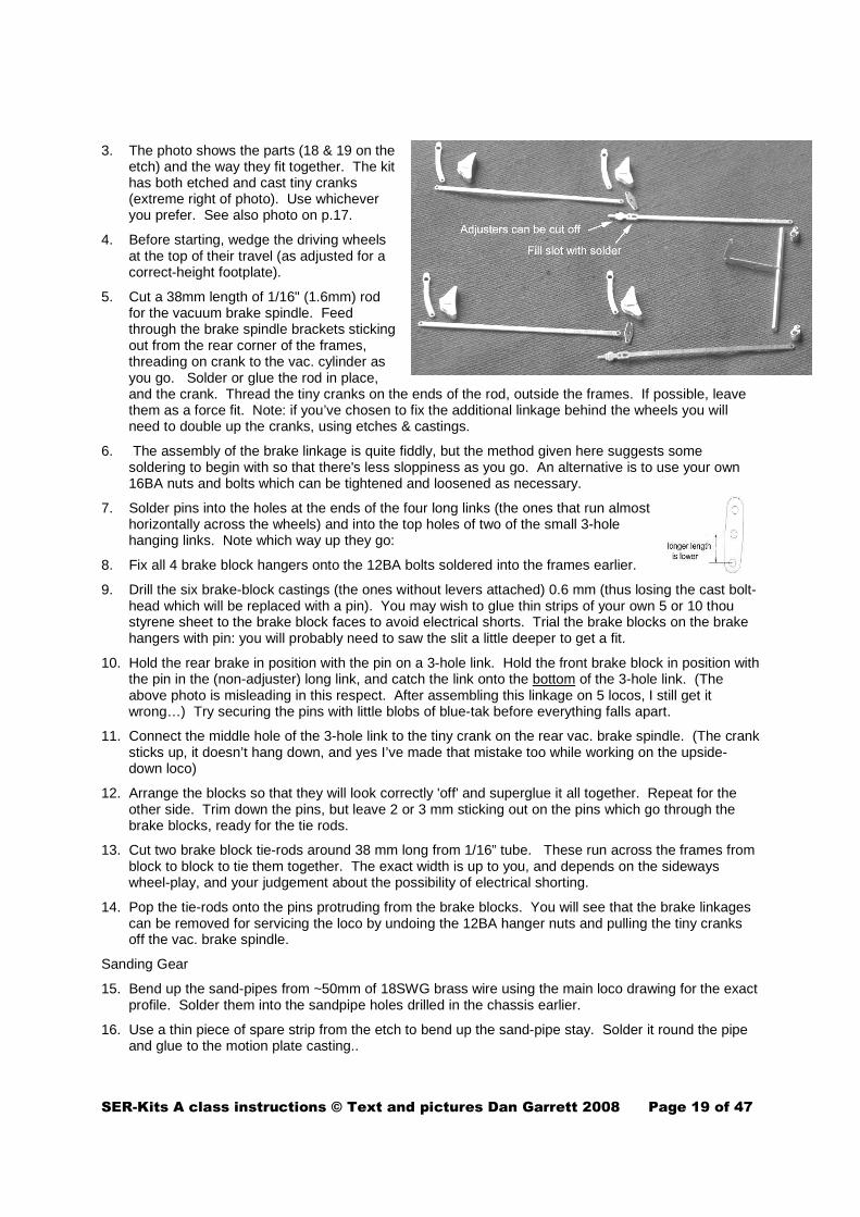
NOTE 2: when preparing the etch, I assumed that the As had adjustable long links at the rear (like all other Stirling locos), and the etch represents the profile of the adjusting screw. (Parts 19) The Ashford draughtsman who prepared the publicity drawing took the same standpoint and drew the adjuster. However, the more I looked at photos during construction, the more I came to the conclusion that the As did not have adjusters. This is a mechanical surprise, and even if not fitted to begin with, I would have expected them to be fitted later on. If you agree with my conclusion, see the photo below, and cut off the ‘adjuster’, fill the slot with solder and then file down the ‘bulge’ so that the rod is a simple parallel all along its length.
SER-Kits A class instructions © Text and pictures Dan Garrett 2008 Page 19 of 47
3. The photo shows the parts (18 & 19 on the etch) and the way they fit together. The kit has both etched and cast tiny cranks (extreme right of photo). Use whichever you prefer. See also photo on p.17.
4. Before starting, wedge the driving wheels at the top of their travel (as adjusted for a correct-height footplate).
5. Cut a 38mm length of 1/16" (1.6mm) rod for the vacuum brake spindle. Feed through the brake spindle brackets sticking out from the rear corner of the frames, threading on crank to the vac. cylinder as you go. Solder or glue the rod in place, and the crank. Thread the tiny cranks on the ends of the rod, outside the frames. If possible, leave them as a force fit. Note: if you’ve chosen to fix the additional linkage behind the wheels you will need to double up the cranks, using etches & castings.
6. The assembly of the brake linkage is quite fiddly, but the method given here suggests some soldering to begin with so that there's less sloppiness as you go. An alternative is to use your own 16BA nuts and bolts which can be tightened and loosened as necessary.
7. Solder pins into the holes at the ends of the four long links (the ones that run almost horizontally across the wheels) and into the top holes of two of the small 3-hole hanging links. Note which way up they go:
8. Fix all 4 brake block hangers onto the 12BA bolts soldered into the frames earlier.
9. Drill the six brake-block castings (the ones without levers attached) 0.6 mm (thus losing the cast bolt-head which will be replaced with a pin). You may wish to glue thin strips of your own 5 or 10 thou styrene sheet to the brake block faces to avoid electrical shorts. Trial the brake blocks on the brake hangers with pin: you will probably need to saw the slit a little deeper to get a fit.
10. Hold the rear brake in position with the pin on a 3-hole link. Hold the front brake block in position with the pin in the (non-adjuster) long link, and catch the link onto the bottom of the 3-hole link. (The above photo is misleading in this respect. After assembling this linkage on 5 locos, I still get it wrong…) Try securing the pins with little blobs of blue-tak before everything falls apart.
11. Connect the middle hole of the 3-hole link to the tiny crank on the rear vac. brake spindle. (The crank sticks up, it doesn’t hang down, and yes I’ve made that mistake too while working on the upside- down loco)
12. Arrange the blocks so that they will look correctly 'off' and superglue it all together. Repeat for the other side. Trim down the pins, but leave 2 or 3 mm sticking out on the pins which go through the brake blocks, ready for the tie rods.
13. Cut two brake block tie-rods around 38 mm long from 1/16” tube. These run across the frames from block to block to tie them together. The exact width is up to you, and depends on the sideways wheel-play, and your judgement about the possibility of electrical shorting.
14. Pop the tie-rods onto the pins protruding from the brake blocks. You will see that the brake linkages can be removed for servicing the loco by undoing the 12BA hanger nuts and pulling the tiny cranks off the vac. brake spindle.
Sanding Gear
15. Bend up the sand-pipes from ~50mm of 18SWG brass wire using the main loco drawing for the exact profile. Solder them into the sandpipe holes drilled in the chassis earlier.
16. Use a thin piece of spare strip from the etch to bend up the sand-pipe stay. Solder it round the pipe and glue to the motion plate casting..

SER-Kits A class instructions © Text and pictures Dan Garrett 2008 Page 20 of 47
17. Reversing lever linkage
The photo shows how it’s all meant to go together:
18. The various parts are numbered 20 on the etch. Before cutting the tiny 3-hole piece from the etch, solder 25mm or so of 1mm wire into the central hole. Then cut it out and fold twice to form the forked piston rod which goes into the steam reverser. Put it aside for later on.
19. The longer vertical forked lever is formed from two half-etch pieces soldered together. I cut mine where arrowed, so that half is fixed to the chassis and half to the superstructure. Next form the smaller forked lever from the two etched parts and solder onto the 1/16" weigh-shaft where it protrudes from the motion plate. (Best to do this when the weigh-shaft is removed to avoid melting the casting.)
20. Choose the appropriate long horizontal link: joggled for locos with leaf springs; straight for locos fitted (later on) with Timmins coil springs. Connect it to the forked levers with pins.
21. In the prototype, the frames bear on the bogie rubbing plate by means of a spring bearing in a housing. This is represented by a casting which glues into a hole in the frames.

SER-Kits A class instructions © Text and pictures Dan Garrett 2008 Page 21 of 47
Section 9: Constructing the locomotive body 1. Choose the appropriate smokebox plate (25 or 25HB).
Fold up Part 25 to form the smokebox front and recessed ‘tray’. For the high-boiler version, you have to cut the ‘tray’ from 25 and solder separately. (Keep the various tiny parts inside the doorholes for later use.) Fit the front footplate (26) and solder in. place. Pip rivets on rear half of buffer beam (27) and solder to footplate and tray.
2. Snip out the footplate (22). If you are modelling a locomotive as it appears in the 1880s, drill out 3 holes to take the fixing and pipes of Smith’s non-automatic vacuum – using the underneath ½-etched holes as a guide.
3. NOTE: the footplate edge is half-etched to appear truer to scale, but this makes it more fragile until the valances have been soldered in place.
4. Locate one valance in the footplate slots and solder in place. (I tack it with higher m.p solder at the tabs, and afterwards run lower m.p solder along the whole joint)
5. Solder the smokebox front and ‘tray’ in place, then solder the remaining valance.
6. The front buffer beam is a wooden ‘sandwich’ on the original, represented by parts 27 (rear), 28 (front) and 28x (a long strip for bottom & edges). I leave out 28x and in the late stages of assembly use a piece of shaped hardwood (as did Ashford)’ so the photos here don’t show the complete ‘box’. If you wish to follow my example, see Appendix A.
Otherwise, punch the rivets, then solder the rear 27 to the valances and front footplate. Next bend up the edges of 28x and solder to 27. Tin the front edges of 28x then the edges of 28 so that when it’s added a touch of the iron will join it without solder getting everywhere. Sweat the drawhook washer plate 28y in place, locating with a thin stick in the drawhook slot.
7. Add the rear draw-plate 24.
8. Between the smoke-box plate and the buffer beam the valances sweep down in an ogee (S) curve. It is probable that these sharp edges had a narrow capping strip to prevent accidents. To form this, tack strip 26X at the top of each ogee, bend down, solder and trim.
9. The rear step plates are a bit fragile, particularly until the steps themselves are in place, so I recommend soldering a strip of spare etch material behind to strengthen them.
10. For fixing body to chassis at rear, solder a 6 BA nut into the half-etched hexagon under the cab. Eventually, the coupling (Etch part 63, along with the tender etches) will be pivoted on the bolt going into this nut.

SER-Kits A class instructions © Text and pictures Dan Garrett 2008 Page 22 of 47
11. Next, consider how you will hold body to chassis at the front as well as the bogie. One way is to solder a 6BA nut in the hexagonal half-etch behind the smokebox plate. A further nut is soldered into the ‘trough’ above the rear of the cylinders to take the bogie pivot bolt. So to assemble, you will first join chassis to body and then screw in the bogie bolt. Alternatively, you can use the bogie bolt as the fixing, which is slightly less fiddly. In this case, forget both the hexagonal half etches. Locate chassis correctly on the upturned body, and mark through the bogie fixing hole onto the footplate. Drill for 6BA and solder a nut underneath the footplate. The ‘trough’ gives clearance for this nut, and the bogie bolt will screw into it and therefore secure the body to chassis.
12. NOTE: the footplate is about ½ mm too long at rear and front to allow for the construction slots. This extra can now be removed(if you wish) so that the footplate ends flush with the rear draw-plate and there is only a slight front overhang over the front buffer beam. Be careful not to remove rivet detail.
13. Fold up two little tabs near the rear. These will support the ‘wood plank’ cab floor. Fold down four little tabs nearby and under smokebox: these locate the body accurately on the mainframe. I find this particularly necessary as the sideplay on the wheels to get round my sharp curves brings them perilously close to shorting on the splashers. The same is probably true for S7.
14. Trial the footplate over the chassis and adjust the fit. I found I had to file the recess at the rear of the main frames a little deeper, and the step in the frames where the cab front will sit.
15. Cut out and fit the cab front, 31 or 31HB. You probably don’t actually need to remove any more of the motor hole, as it’s covered by the backhead casting anyway. However, it can be useful if you’re fitting a flywheel, as you can see any fouling problems, even at a late stage. You may need to remove more of the lower area to make room for the gearbox. . At the wheel arches, there are extra bits of ½ etch as ‘scaffolding’ to hold everything together and slots to make it easier to fit the awkward little ¼ splashers to the front of the cab. This ‘scaffolding’ is removed later.
16. Solder a spectacle rim (Parts 31x etched inside one of the smokebox plates) to the front of each glazing hole, but work from the rear so that you can check the centring. (I’d forgotten to fit them, as you can see in the photo and it was a pain later on) The two spare rims are for retaining the glazing in the last stages of assembly – keep them safely.
17. Locate the cab on the tabs on the footplate and solder in place. (Yes I know it’s all very flimsy at this stage.)
18. Solder the rear ¼ splasher sides into the slots, but it’s best not to fit the tops yet.
19. Remove the cab sides (32) from the etch.
20. Standard locos: At the top of each side is a half-etched line. Cut here.
Wainwright high-boiler loco only: re-drill the handrail holes 4.3 mm higher and fill the etched holes with solder.) Fill the ½ etched line at the top of each side with solder.
21. Curve the cab sides to the correct profile using the spectacle plate as template. It’s best to form the top shallow curve first. Check the fit at the top. I found I had to remove about ¼ mm from the top of each side.
22. Catch the bottom of the sides to the footplate with solder. Then solder the sides to the spectacle plate (which fits inside the sides so that the final cab width is 42mm.) I found it helpful to hang the body over the side of the bench, supporting the cab front on a piece of wood. The sides rest on the block for alignment. As with valances, I find it best to tack with solder in one or two places, get the

SER-Kits A class instructions © Text and pictures Dan Garrett 2008 Page 23 of 47
curve absolutely right, and then tack the top before running solder all along the joint. Don’t rush this, and don’t be too economical with the solder in the corner – you don’t want the cab to come apart at a later stage.
23. Join the cab sides at the top with the joint plate (33) flush at the front to leave room for the beading at the rear.
24. The cab beading (30) has an etched locating groove. It may help first to anneal the part by heating up near to red heat, allowing to cool slowly and then cleaning up. I also find it best to cut the beading into two unequal parts. (Unequal so that the join is not at the top.) Starting from the handrail, bend the first curve, and catch the beading in place with a little solder so that the hole for the grabrail is centred 1.75mm (3 scale inches) away from the cab edge. Now work your way little by little. When you get to the top curve, clamp the beading and gently bend around with fine-nose pliers to fit. Don’t rush ahead - get each part of the curve right before you go on! Then work back on the other side. I found I had to trim about 1mm. off the beading. Finally, the edges of the beading should be rounded off.
25. For the high-boiler version, the beading will be too short. So find a scrap of N/S about 10mm wide and file a groove across the width. Then cut the scrap down to about 1mm on either side of the groove. Solder this piece into the gap, and file to the correct size.
26. Choose the appropriate front splasher sides (34) depending on whether or not you are making a version with integral sand-boxes, and solder into the footplate slots. Don’t solder the tops yet. NOTE: the non-integral (semi-circular) sides are NOT interchangeable. There’s a little cutout at the front to clear the sandbox castings, so make sure you get them the right way round.
27. Bend the inside cab wheelbox sides 40 to fit the profile of the tops 41. The holes in the sides are for lever castings later on, and should be nearer the front. The tops are soldered inside the sides. Check that the soldered boxes are square in all directions, and don’t taper at the bend (which easily happens). Locate the boxes in the slots in the footplate and tack in place at that point. Check that they sit squarely and the tops are level. I found it best to tack the top to the spectacle plate next, check again, and then join along the top sides. They’re always a pain to fit neatly.
28. File away (with file or burr in drill) all the unnecessary bits of ‘scaffolding’ until the footplate sits down over the rear wheels without fouling them. Clean up.
29. Bolt the footplate to the underframe, run the loco and check that the front wheels don't touch the wheel-box sides on your sharpest curves. I recommend leaving the main splasher until you’ve trial-fitted the boiler.
30. Add the ogee (S-curved) cylinder cover plate (29) in front of the smokebox wing-plate as follows. Bend the S-curve over a piece of ¼" or 6mm rod caught in the vice, using the ogee sides 29x as templates. (The etched holes for the knobs go nearest the smokebox, and the rest is intended to stretch as an overlay up to the buffer-beam.) Then put a slight upward curve across the top of the cover-plate where it will join the smokebox plate. This curve can be seen in the elevations, and the A is the only Stirling loco to have this complicated little feature.
31. Sweat the ogee sides into the sides of the ‘tray’ where they will act as hidden formers. Offer up the cover plate and adjust the curves until it sits snugly in place on top of the formers, checking from underneath.

SER-Kits A class instructions © Text and pictures Dan Garrett 2008 Page 24 of 47
32. Before soldering the cover-plate, I found a piece of wood with an end profile approx. 10 x 27mm, and held it upright in the vice. The loco body was then turned upside and the ‘tray’ fitted over the wood catching the cover plate in position – as in this photo:
33. After cleaning up, solder cut-down pins into the etched holes for the knobs – they can be caught underneath in etched ovals in the smokebox wing-plate.
AT THIS STAGE, PREPARE THE RESIN BOILER SO THAT YOU CAN MAKE TRIAL FITTINGS. Section 10: Preparing the Resin Boiler 1. The boiler is a multi-purpose casting to suit all of Stirling's locomotives, except the B, and will need a
degree of shaping. The smokebox saddle and firebox are approximately the correct height for the high-boiler version, but need cutting down as explained below for earlier versions. The length of the firebox may need to be reduced.
2. NOTE: Resin is a brittle substance but the boiler is thick enough to withstand cutting and drilling. However, take care and don't force the tools or you may snap thin parts of the casting. If this happens, the casting can be glued with Superglue.
3. First, clean up the casting: remove flash (casting projections) with fine glass-paper and a fine flat file. Use very fine glass-paper to take the shine off the resin so that paint will adhere well later. There are some unavoidable bubble-holes at the join between smoke-box boiler, and these should be filled with resin glue or Milliput for filing flush later.
4. Hold the boiler upright, and rub it backwards and forwards a couple of times across a sheet of medium glasspaper glued or pinned to an offcut of MDF. Inspect where you've sanded, to see whether any corners of the bases of the smokebox saddle or firebox are high or low. Also check that the boiler top is horizontal when the boiler is on a horizontal surface. You may need to sand with more pressure on the saddle or firebox until the boiler is truly horizontal, but remove very little at this stage. Also check the smokebox front for true 90 degree uprightness. It may need a very little sanding off at top or bottom, but usually not.
5. Firebox length: Check the fit of the boiler. File the rear firebox edge until it slides in snugly. If you’ve had to reduced the rear boiler strap too much to look right, file/sand it flush with the boiler. There’s a replacement etched as Part 39
6. Measure how much you need to lower the boiler. The idea is that the top of the smokebox should be 1/4 of a millimetre (or thereabouts) below the smokebox front – Stirling's actual smokebox plate stands proud of the smokebox by about 3/8" all the way round. For the original lower boiler, you will need to cut the casting down around 5mm, so scribe a cutting line around the saddle and firebox.
7. Clamp the bottom (waste part) of the smokebox in a vice, without overtightening, and carefully and gently saw part-way through. (See photo below) Don't go too close to the marked line, so that you can finish with file/glasspaper. Re-set the smokebox in the vice to work in turn from the other side, the front, and the rear. TIP: The resin dust tends to clog the saw, so clean frequently. A drop of oil can help to avoid the saw binding. NOTE: the boiler bands are lower than the smokebox saddle (projecting into the motion hole), so don’t saw or file them off.

SER-Kits A class instructions © Text and pictures Dan Garrett 2008 Page 25 of 47
DESIGN CHOICE: There are a couple of ways of fitting the boiler to the brass etch. The easiest is to glue it into place with a 2-part resin glue – but leave this to a late stage. However, a removable boiler is helpful for painting and especially lining. In this case, one method is to drill and tap holes into the firebox sides and smokebox saddle. Appropriate holes are etched into the footplate to take 10 BA countersunk bolts, but those for the firebox may need to be slightly bevelled so that the bolt-head sits flush without fouling the chassis. Alternatively, if you don't have a 10 BA tap, glue sawn off bolts into holes drilled into the boiler casting and fix with nuts. Holes in the front chassis spacer give clearance for the smokebox nuts, but clearance slots must be filed in the frames for the firebox nuts.
8. Repeat the process with the firebox, and finish off by filing & sanding. Place the boiler on a level surface with (say) 60 thou styrene strips under firebox and smokebox to allow for the boiler band clearance, and check it’s true and the top is horizontal.
At this stage, the boiler should be a neat fit on the footplate, and should sit flush all round without twisting the footplate. (Sight along the bottom of buffer beam and rear draw-plate.)
9. Transfer the outline of the rear ¼ splashers onto the firebox with a scriber. Carefully saw off the rear lower corners of the firebox to near the scribed line. Cut wheel recesses at the front of the firebox, but this is tricky so take off tiny slices at a time, or use a burr in a drill – but be careful it doesn’t slip. You don’t need to go very deep – 2 or 3 millimetres. If you do overdo, fill gaps with Milliput later on when you fit the tops of the splashers.
10. Mark out the motor hole, allowing clearance around the 10 BA fixing holes (if you're using this method). If you plan to glue the boiler in place, a simple rectangular hole is sufficient.
11. Cut out by drilling a series of holes with a bit size around 2 or 2.5mm. Any raggedness will of course not be visible in the finished model. It's safest to drill corner holes first, and then drill the holes between them. In the photo, I've cut out the rectangular shallow part of the casting first, but it's probably best to leave this in place, cut out the main (square-ish) hole to clear the flywheel and then saw and file out the motor slot. Unlike the photo, it's best to support the boiler gently in the drill vice or in a trough made of three strips of wood.
12. Place the boiler in position on the etch assembly, and trial fit onto the chassis. The trick is to lower the boiler over the flywheel, and then slide the body backwards until the rear buffer beam drops into place. When satisfied, continue to assemble the body, but do not yet glue the boiler into place.

SER-Kits A class instructions © Text and pictures Dan Garrett 2008 Page 26 of 47
Section 11: Completing the Loco Body
34. If you’re making the version with integral sandboxes, solder the fronts 35 into the slots in floor & sides.
35. The ½ etch splasher tops are intended to fit into a narrow ½ etch rebate along the top of the sides. The exact shape to fit snugly against the boiler is beyond my design skill, so I’ve etched them too wide. The final shape is approximately as in the diagram, so I suggest trimming roughly before soldering in place. You can then offer the boiler, and slowly file away, a little at a time, until the boiler fits snugly.
36. Separate sand-boxes, Parts 37: Each box has a top and bottom and ½-etch sides. Bend the side pieces to fit into the rebates in top and bottom with the join out of sight. Solder the sides, so that slight lips are visible top and bottom. File off part of the bottom lip if it fouls the wheel aperture.
37. Solder the boxes onto the footplate. (Because of lining them later on, I made them removable by sweating a piece of 1/16 brass inside the bottom, and drilling & tapping so that they could be held by a 10BA screw.) The oval filler caps 38 are best soldered before cutting from the number tag. Solder the smaller oval, file off the joining tag, then solder the larger oval, and finally remove the number tag.
38. Trial the 'wooden' floor 42 inside the cab and trim if necessary. I prefer to fix it later, but at this stage add the handwheels and brackets for the water supply cocks. Make up handwheels (See Appendix C), fold and thread brackets 43 onto the wire spindles, and solder to the correct distance below the handwheels. Solder each handwheel spindle into the holes etched at the rear of the floor. It’s easier to leave the brackets ‘in mid-air’, and glue them to the wheelbox sides after painting.
39. There are three lamp-irons 44 for the buffer-beam and one of similar length which should have the bottom curled up and be fixed centrally between chimney and smokebox door. The curl is to hang the 24" x 18" oval board (etched with Headcodes) when the loco is hauling a 'Special'. The curl is 1/2-etched – be careful not to mistake it for part of the tag. The three identical lamp-irons should be folded into the shape shown. Do this while they’re still in the etch, so that you can fold them identically. Fill the fold with solder. Then insert each lamp iron into the hole in the footplate until the rear projection sits in the recess. Solder in place.
40. The cab steps 45 (top) and 46 (bottom) can be folded and soldered at this point, or later on when detailing, since there are no castings near them. Note that the lower steps are L- and R-handed to match the curve.
41. The front single steps 47 are fairly fragile and I suggest soldering them at a later stage, adding a piece of N/S wire behind them for strength, bending the wire at right angles so that it can be soldered to the footplate. The fastidious will remove the etched leg and replace it entirely with wire.
(It's probably best to solder up the tender etches at this stage – Section 13, and then work on white-metal fittings for loco and tender at the same time.)

SER-Kits A class instructions © Text and pictures Dan Garrett 2008 Page 27 of 47
Section 12: Detailing the Loco (castings) 1. Add the boiler fittings, but do all the
drilling first so as not to damage individual components.
2. Firstly, identify the fittings from the photo. The clack valves and the take-off valves need drilling 1mm diameter, 1mm deep to accept pipes. Note that the injector take off valves each have two unions (nuts) and the smaller ones need drilling 0.6mm diameter, 1mm deep to accept 26 SWG wire spindles for handwheels inside the cab. (The photo wrongly states 0.5mm) (NB. Omit the ejector take-off valve for an A with Smith’s non-auto vacuum)
3. Next drill the boiler holes.
4. Place the boiler in position on the foot-plate and pencil a top centre-line. With reference to the plan, pencil the positions for the chimney, safety-valve, ejector steam take-off valve (the round valve with lever-handle – omit for Smith’s non-auto vacuum) and the whistle. Remove the boiler and drill 1mm pilot-holes for all of these. Carefully open out to 6 mm for the chimney, 5 mm for the safety valve, 1.2 mm for the whistle and 1.8 mm for the ejector valve.
5. Mark the positions for the injector take-off valves on either side directly below the whistle, so that the small glands line up with the holes in the cab front for the handwheel spindles. Drill boiler 1.8mm.
6. Referring to the loco drawing, mark the position for the clack valves, and drill 1.8mm, parallel to the footplate, NOT radially to the boiler centre.
7. Handrail knobs: Mark a line along each side of the boiler 1.5mm lower than the centre line of the handrail on the side of the cab. Then mark a similar line on the smokebox 1mm higher than the boiler knobs, viewed from the side. Referring to the loco drawing, measure and mark the positions of the handrail knobs along these lines. (Note the odd position for the right-hand smokebox knob if Smith’s non-automatic ejector is used.) Drill out 1.3mm for a tight fit.
8. Smith’s non-automatic ejector: The casting fits in the 3 holes drilled earlier in the footplate by the smokebox. The vertical pipes are intended to curve into the smokebox, so mark where they will enter, and drill the two holes, angled upwards, and then open them out into vertical ovals. Cut down and curve the cast pipes until the casting fits. On the original locos, a rectangular ‘patch’ can be seen around the holes. This can be made from a small piece of shim or styrene, and will hide any gaps. Next, drill a 1.6mm hole just below and behind the chimney as in the drawing to take the release valve. The pipe from this casting curves at the bottom into the ejector casting, which can be drilled 1.2mm. A little cast ‘nut’ should be pushed on before gluing. A thin rod runs back to the cab – use thin wire after painting and lining.
9. After cleaning up the appropriate chimney, trial it on the smokebox with the boiler in place on the loco. Check with a set square that it's vertical. If not, open out the fixing hole one side or the other. When satisfied glue in place. (You can juggle on your own 0 BA nut, if you wish).

SER-Kits A class instructions © Text and pictures Dan Garrett 2008 Page 28 of 47
10. Clean up the safety-valve. Cut about 2mm from the centre of the flat rod between the valve pillars and work the short brass spring into place. Superglue. Trial and fix on the boiler as for the chimney. (TIP: sight along all the fittings from cab-centre to chimney)
11. Clean up the clack-valve castings, then mark and drill underneath 1mm to accept the copper wire for the pipework. For the first couple of decades, the locos seem to have had handwheels to isolate the valves, but in SE&CR days they were discontinued. If fitting handwheels, it’s probably best to replace the cast spigot and drill out 0.55mm where the spigot was. Make up handwheels (Appendix C) using small handwheels. Glue the clack valves into place. Bend ~25mm pieces of 0,9mm copper wire into an ogee (or open S) and glue them into the holes under the valves, so that they curve out of sight behind frames. I add the handwheels after painting.
12. Automatic vacuum locos: Glue the ejector take-off valve in place and trial a piece of 1mm copper wire curving down and into the cab.
13. Trial the injector take-off valves in place, and temporarily thread 26 SWG wire through the cab-holes and into the glands to check that everything lines up. When satisfied, glue in place
14. Glue the whistle in place.
15. Bearing in mind the difficulties of adding the black & white lining, fix the boiler finally in place. Glue the boiler strap – etch part BS – to the boiler, against the cab front.
16. Smokebox door: clean up the casting, and gently file away the edges until it's a snug fit into the smokebox front. Glue in place. Drill out the central hole 0.9mm and add the handles. (Don't confuse the smokebox handles with the smaller but similar water-cock handles for the tender)
17. Handrails: cut short pieces of 22SWG N/S rod for the cab rails, feed onto short knobs and glue or solder into the cab sides. Curve the front hand-rail from 22 SWG N/S wire, thread on short knobs and glue or solder to the smokebox front. Thread 4 long knobs and 1 short onto N/S rod cut to length for the boiler hand-rails. Trial fit, and if necessary open out one or more boiler holes until the handrail is straight and parallel with the foot-plate. Superglue in place.
18. Buffers. Check that the buffers slide freely and superglue the nuts to the spindles. Glue the buffers in place on the buffer beam, with just enough glue. (Too much and the buffers may lock solid!) The holes in the buffer beams (7mm either side of the drawhook) are for safety chain eyes. Use either the castings supplied, or cut 4 x 3mm squares of scrap brass (for the square washer plates), drill out 0.6mm and solder over the etched holes. Form 4 'eyes' from 24 SWG wire and solder two of them into the holes. Set aside the remaining washer-plates and eyes for the tender.
19. Vacuum Pipes. Automatic version from ca.1890. This can be soldered with low-melt solder underneath the buffer-beam. Because I made a wooden sandwich buffer-beam, I devised a 'pipe-clip' as follows. Cut a piece of scrap brass, bend into an Ω shape to fit the horizontal pipe, drill the sides and pin to the buffer-beam, as in the photo. TIP: this method can also be used with a metal buffer-beam if you prefer not to solder the casting: solder the pipe clip in place, and glue the vac. pipe into place after painting and lining.
20. Smith’s non-automatic vacuum (1880s). For the front standing pipes: Drill two 1.3mm holes in the footplate behind the front buffer beam, 21mm apart and 5mm from the front of the (filed-back) footplate. (5 ½ if you can’t be bothered to file back). Glue the standpipe castings in place. Curve the hose casting and glue in place.
21. Fit the appropriate long link for the cylinder drain cocks (Part 45 or 46) alongside the boiler, soldering to footplate just behind the smokebox.

SER-Kits A class instructions © Text and pictures Dan Garrett 2008 Page 29 of 47
Section 13: cab fittings.
1. It's probably easier to paint the cab interior (green with Cudworth green livery and possibly a creamy-brown with Stirling black livery) before adding the fittings. Paint one side of the spare spectacle rims while you're at it.
2. Cut glazing 7.5mm diameter. (Use the spare spectacle plate as a template) Secure with the spare spectacle rims.
3. The cab layout differs between the first and subsequent batches. I advise studying the scale drawings carefully before beginning. One photo below shows the Early O backhead which is probably the same as the first four As and possibly all of the locos for their first decade or so. When reboilered it is likely that the backhead was the same as for the later O. You will see that the kit contains several redundant parts depending on which version you model.
4. Identify the parts against the photos and separate those you need. Note that the rivet heads are a useful grid for correctly locating the fittings. You will need to drill extra holes in the backhead to take the spigots on the fittings, and also small holes in the fittings to take wire representing handles and pipework. Details follow below. Handwheels fit on spindles on the relevant castings, and these spindles should be gently tapered so that the handwheel is a 'force-fit'.
5. The back-head (rear of firebox) is full width. In order to fit between Fine-scale splashers, about 1.5mm must be removed either side. After getting a trial fit, I found it easier to add all the fittings and paint the back-head before final fitting.
6. There is no direct evidence for the backhead fittings. Probably the first four locos had the same backhead as the early O. As for the remainder in the first decade of their life, who knows? When the locos were reboilered, they may have had fittings as the later O. If you are modelling the loco when fitted with the automatic vacuum (i.e. after ca.1890) then you must fit the ejector casting. This affects the linkage of the reverser, and instead of the double lever (top right of early O backhead photo, the front reverser valve link is replaced by a handle casting.
7. Start by drilling the extra holes needed in the backhead. Most of the diameters are shown in the photos. Drill sizes missing from the Later O photo: 0.9 mm for the 'tap-
handle' cocks and 1.6 mm for the ejector.
8. Next drill holes in the fittings themselves:
• Water gauge -drill 4 holes 0.55mm in the water-gauge, 3 for the handles and one for the bottom drain pipe. Handles should be bent from 26SWG brass wire and fitted at this stage

SER-Kits A class instructions © Text and pictures Dan Garrett 2008 Page 30 of 47
• Oiler (if oiler it is…) cut off bottom short cast pipe and drill 0.55mm to take wire pipe.
• Early O: adapt oiler casting and drill 0.55mm hole in end for wire 'pipe'. Also drill 0.55mm hole in funnel.
• Vacuum brake ejector (NOT Smiths): as shown in the Later O photo drill 2x1mm holes and 1x 1.3mm through the unions (nuts) to take pipes
9. After drilling, the various fittings can be glued into position on the backhead and handwheels added. (See Techniques Appendix)
10. Glue Pressure Gauge (and Brake Vacuum Gauge where appropriate) to the spectacle plate and add 28 SWG/0.4mm copper wire as in Loco drawings. Then add pipework:
11. Glue the backhead into place.
12. Bend 2 x ~60mm pieces of 0.9mm copper wire to form the pipes from the injector take-off valves each side below the whistle, through the cab front, and down to the floor.
13. Vacuum fitted locos: Bend ~75mm of 0.9mm copper wire to form the pipe from the ejector. It runs over the top of the firebox, through the cab front and then curves to meet the ejector take-off valve fitted on the boiler beween whistle and safety-valve. Two pipes emerge from the bottom of the ejector. The right-hand is ~17mm of 0.9mm copper wire. The left is ~30 mm of 1.2 mm copper wire bent forward as in the loco cab side elevation. The photo shows a 'union' made from a 10BA nut.
14. Fix the two injector handwheels above the backhead, threading their wire spindles into the glands on the take-off valves. Bend a short piece of wire into an L and fix into the whistle to form the handle.
15. Reverser: File off sprue remains so that it sits happily on the wheel-box top. Drill 1.2mm for rod to reversing lever, and drill 1.6mm as shown for spigot. Drill top of front cock lever 0.5mm. Add to reverser and link with wire to the double handle on the backhead.
16. Glue the lever castings into the wheel-box holes on either side of the cab after trimming the spigot down so as not to foul the wheels.
17. Cab railings: the castings are pliable enough to be bent while springing into place and then straightening up. The intrepid will – after gluing them in place – drill 0.65mm diam. down into the top of the casting and fit a cut-down pin to represent the knob.
18. Fix the assembled floor and injector cocks. Glue brackets 36 to the splashers.
19. (After painting) add the Slaters drawhook and screw couplings – follow their instructions carefully as reverse threads are involved. Cut safety chains from the length of chain supplied, fix to the 'eyes' and add the hook castings.

SER-Kits A class instructions © Text and pictures Dan Garrett 2008 Page 31 of 47
Design choice: You can either follow prototype practice and arrange for the cast external axle-boxes to be sprung.in the outside frames or support the wheels with a non-prototype subframe (Part 67) and sliding brass axle-boxes. Note that your choice affects the type of wheels, as discussed in Section 2. In either case, you may prefer to make life easier by springing only the centre wheels.
Section 14: Constructing the tender – etched parts
1. Remove the subframe, 50. If you’re following prototype axlebox springing, cut off the non-prototype internal horn-blocks (axle box guides). The remaining sides of the sub-frame represent the extra water tank. Arranging sprung axleboxes is is given later (Instruction 1)
2. Fold the subframe so that it has squared-U cross-section.
3. Internal sub-frame springing only: Treat the axle-box guides 52 as for the loco by cutting a thread in the tags and bending them up. Solder them in place, inside the subframe, using the etch lines as guides. Partially screw in 12 BA bolts – they can be adjusted through the semi-circular cut-outs. The photo shows what all this will eventually look like.
4. Remove the vacuum cylinder support 51. Solder a 6BA nut into the ½ etched recess. The other hole with a circular recess is for the loco-tender coupling. This is a 6BA bolt with most of the thread removed and the end filed to a point. If this is problematic, use an 8BA bolt which is also the correct diameter for the coupling. Whichever, solder the bolt in place.
5. Spring the vac. cylinder support into the subframe slots as in the photo. Solder in place.
6. Cut a piece of 1/16” brass rod a little wider than the sub-frame to form the vac. crank spindle. Thread the vac. crank 53 onto it, and solder the spindle into the vac. brake hangers allowing the crank to remain free.
7. Form the sand-pipes from 2x 36mm lengths of 18SWG copper wire, bent at right-angles 10mm from one end. Thread the short ends through the holes in the sides of the sub-frame and solder to the vac. cylinder support as in the photo.

SER-Kits A class instructions © Text and pictures Dan Garrett 2008 Page 32 of 47
8. Solder the guard-irons 54 to the rear of the sub-frame. For strength you can drill through the half-etch rivet holes rather than punch them, and pass wire or pins through the holes for strength.
9. Remove the side frames, 55, and remove the various small parts connected to them and keep safely. Attached to the front of each etch is a small circle with a hole in the middle, and another small circle (56). Remove these, punch rivet holes and solder or superglue to the frame to make the main brake rod bearing.
10. Punch all the other rivet holes. However, if you look at the drawings and photos, you will see that the prototype spring hangers are fixed to rods with quite large flattened heads. These are catered for in the half-etched rivet positions, but you will need a larger, flatter punch. It is better to drill the centre of these holes 0.65mm diam and use pins with the heads flattened.
11. Bend the axle-box guides outwards.
12. Remove the footplate 57, taking care with the ½ etch edges. Solder the frames in place. (Make sure they face the right way!) NOTE: the photo below shows an O tender, but it’s almost the same.
13. Punch rivet heads in the rear buffer beams 58. NOTE: One of the ½ etched rivet heads is missing (It’s the lower of a column of three) but can easily be marked and punched.
14. Solder the front and rear buffer beams 58 and 59 to the footplate and frames
15. Sweat the beading 60 to the frames underneath the footplate on each side. NOTE 1: the returns are uneven, so match before soldering. NOTE 2: the beading is slightly short to allow for solder fillets at either end, so make sure there’s an even gap at each end before soldering.
16. Prototype sprung external axleboxes only: NB: photo shows the similar O tender. There are six tags (Etch Part 64) to guide the axle-box. Cut them out, run a 1.2 mm drill through each hole, and bend them along the etch line. Solder each tag into the ½ etch rectangles behind the frames above each axlebox.
17. Solder the drawhook washer plate 61 onto the rear buffer beam, locating it by the drawhook slots.
18. Remove ½ mm extra overhang from rear of footplate if desired.
19. Take the steps 62 and fold up the fixing tab. Note that the lower steps are L- and R-handed to match the frame curve. Solder the steps in place but note that the first four locomotives appear to have had the step a little lower than the ½ etch recess. In this case, fill the recess with solder and check the drawing for the alternative position.
20. Remove the water tank 64. Note that there are various ½ etch lines – some for folding & some for locating parts. There are only THREE folds to be done – folding down the 2 sides and the rear. The fine dotted lines on the sides & end are for locating the flares.
21. After folding down sides and ends, solder the rear vertical joins. FOR A REMOVABLE BODY: Spring the cross-piece 65 into the locating lines and solder in place and solder a 6BA nut into the ½ etch recess.
22. Locate the tank front 66 in the ½ etched internal lines of the sides and into the top slots. Solder in place.

SER-Kits A class instructions © Text and pictures Dan Garrett 2008 Page 33 of 47
23. Take the bunker front 67 and fold the top at right-angles, EXCEPT if you are modelling the first batch of locos as originally built. For these locos, you should probably cut off the fold at the ½ etch line (There seems to be no photographic evidence, so this suggestion is based on the way the O tender evolved. I additionally laminated a thin strip of N/S waste across the top as there was probably a strengthener.)
24. Take the shovelling-plate 68 and check that the front 'tongue' fits through the coal-hole in 67. Ease it into place – it should be sloped slightly downwards to the rear (see dotted line on drawing. Before soldering:
25. Trial the tank on the footplate. If you are NOT going to make the tender body removable file a 6BA nut to about half its thickness and solder it in the hexagonal recess in the footplate under the shovelling-plate. Then solder the shovelling plate from underneath, and finally solder the body to the footplate.
26. If you are going to make THE BODY REMOVABLE, file a 6BA nut to about ½ its thickness, and place it temporarily in the hexagonal recess in the footplate under the shovelling-plate. Arrange the slope of the shovelling plate to clear the nut, and solder the plate in place. Remove the nut, replace the body in its slots, turn the tender over, and drill a 2.9mm hole (No.33) through the nut clearance hole into the shovelling-plate. Locate the nut under the shovelling-plate with a matchstick and solder in place. The two 6BA tender securing bolts will now hold the underframe, footplate and body all together.
27. Sweat the coal-door 69 over the coal-hole (see tender drawing).
28. The tender sandboxes consist of top lids and ½ etched sides, 70. Curve the sides around 3/32” rod to fit into the lip under the lids - they are intended to be about ¼ mm larger than the lids so that they can fit into ½ etch grooves in the bunker front and sides. Solder sides to lids and trial the made-up sandboxes into the grooves. Solder the sandboxes either side of the coal-hole.
29. Choose the appropriate side flares 71 and the end flare 72. Curve them over a piece of 6mm (¼") rod (as in the photo) working backwards and forwards a little bit at a time. Do not attempt to bend right over in one go or there'll be a lot of distortion. Sweat them in place to just cover the half-etch guidelines. Be very sure to make the lower edge straight and level.
30. Adjust the curves to the drawing and run a fillet of solder into the rear corners. Round the top edges with a file.
31. Top Toolbox. Fold the sides 73 and solder the end inside the side. Bevel the lower edges of the corner straps to fit into the etched locating line on the tank. Fold and tack the ‘roof’ 74 in place. Once you’ve got the over-hang correct all the way round (a bit ticklish) you can run solder along the joints. (I prefer to make items like this removable, and soldered a brass strip across the bottom which was then tapped to receive and 8BA bolt.)
32. Joggle and solder the three lower lamp-irons 75 as with the loco lamp-irons, and solder into the etched holes at the rear of the tender footplate. The fourth is bent to fit the rear flare and soldered centrally. However, you may wish to leave soldering it until after fitting the brakes and castings as it's vulnerable. It's far enough from the tank filler casting for heat not to be a problem (unless you dwell for ages with the iron!)

SER-Kits A class instructions © Text and pictures Dan Garrett 2008 Page 34 of 47
33. If you are modelling the first four locos in the first decade or so of their lives, you may decide to fix sanding lever brackets 76. (See historical notes) Solder the brackets to the front of the bunker.
34. The soldering work on the tender body is now virtually complete.
Section 15: Springing loco & tender, adjusting the running, and fitting tender brakes
For the non-prototype internal bearing method, follow instructions 1 - 3. Follow instructions 4 to 9 for sprung axleboxes. Note that you may well not need to spring all 6 wheels. One of my tenders has fixed front & rear axles, and only the middle one is sprung. It seems to run as well as the fully-sprung tenders. (However my layout is Finescale not S7)
1. Cut 4 x 6.5mm springs and 2 x 6mm from the 2.4 diam phosphor-bronze spring. Work the springs between the adjusting bolts and the axleboxes. (shorter springs in middle) Add wheels and axles to the sub-frame, packing with washers as necessary. It's best to have no side-play on the rear wheels, a little on the front, and most on the middle axle. Run the sub-frame around your tightest curve, and re-pack the washers as necessary.
2. Rest the tender body on the subframe, and load the tender with the bigger castings – toolbox(es) and filler cap – in the correct position. By adjusting the 12BA screws and – if necessary – removing and trimming the length of the springs, arrange things so that the top of the footplate is 30.5mm above the rails (and horizontal!) Add the loco-tender coupling (Etch part 12) – see earlier diagram. Couple up, and have a trial run round. Check the distance between loco and tender against the drawing, and – depending on the sharpness of your curves, you may be able to close the gap a little by putting a joggle in the coupling.
3. Bend back the etched keeper plates and fit the cast (external) axleboxes. Glue in place. Now go to Instruction 10
Sprung Axleboxes
4. Clean up the axle-box castings, so that they slide freely in the guides in the brass frames. The spigot may be bent if necessary with fine-nosed pliers into a slight dog-leg so that it slides easily up and down in the tag 47. However on uneven track it’s possible for the spigot to pop out. One solution is to bend the tags slightly down. Better still, cut the rod off, drill a hole and replace with wire rod a bit longer than the original.
5. Before going any further, cut springs from the stiffer of the fine springs (1.6mm diam, and stiffer than the plunger pick-up spring). The springs should be – from front to rear – 5.5mm, 5mm, 5.5mm. The springs ping easily and dematerialise, so I find it easiest to clamp an axle-box gently in the vice, drop the spring onto the spigot and cut it to length with a pair of fine scissors. Put the springs into a tin-lid where they won't get lost.
6. Axle by axle, check the wheel-sets fit and rotate freely. The axle-boxes are cast with holes to take Slaters 0.1" top-hat wagon wheel bearings, and I use these for Slaters MF wheelsets. (Yes I know they don't have needle bearings, but it seems to make no noticeable difference.) Provided the bearings are pushed home, the holes will probably need no further drilling for a snug fit. However, to get the tender round sharp curves the middle axle-box holes may need to be drilled out a further ½ - ¾ mm with a 2.5mm drill. Make sure there is virtually no side play on the rear axle, to minimise the risk of buffer-lock. If you have very sharp curves, it may help to allow some play on the front wheels.
7. Fitting the springs can be ticklish, but this method works for me: with the wheel-sets still in place, lay the tender on its side, ease one of the axle-boxes out, until there is enough room to fit a spring held in tweezers, as in the

SER-Kits A class instructions © Text and pictures Dan Garrett 2008 Page 35 of 47
photo. Ease the axle-box carefully back in, making sure the spigot goes correctly into the tag-hole. Bend the keeper plate partially back into positon to prevent the axle-box falling out. Repeat for the other axle-boxes.
8. Sprung this way, the tender should - once the castings have been fitted - sit on the track at the correct scale height, with the footplate top 30.5mm above the rails - and horizontal!
9. If height adjustment should prove to be needed, then the axleboxes will have to removed and the springs cut shorter or stretched slightly. Once you’re satisfied, then bend and glue the keeper plates into position. If you have to do lots of adjustment, the danger is that the keeper plates will break away. If this happens, all is not lost. Drill through the rivets and frames 0.6mm and secure the keeper plates in position with pins soldered or glued.
Then, whichever method you’re using:
Add the loco-tender coupling (Etch part 63) – see earlier diagram. Couple up, and have a trial run round. Check the distance between loco and tender against the drawing, and – depending on the radius of your curves, you may be able to close up the gap with a small joggle.
Making up the brakes:
WARNING: If you're using sprung axleboxes as in the prototype, make sure the tender height is finalised at this stage. Once the brake gear is fitted, adjusting the springs will require major surgery!
55. The above photo shows what you’re aiming for. Drill 1/16" (1.6mm) into the bottom of the vacuum cylinder casting to take the vac. piston rod, and screw the casting into hole & 6BA nut in the sub-frame support, part 51.
56. Cut a 46.5mm length of 1/16" (1.6mm) brass rod as the main brake crank spindle. Thread on: the brake handle link and crank 79, one ‘tiny’ crank (either the casting or the etch 78), and) the crank for the vac cylinder 53, followed by the final ‘tiny’ crank. (As in photo, but the brake crank will be vertical when fitted, not horizontal)
57. Pop the rod into the bearings in the frames. You should bend over the brake handle link and solder to the floor, but do not solder the other end to the brake spindle - then you can disassemble the tender if necessary.
58. Cut a 25mm length of 3/64" (1.2mm) diam. brass rod, thread through the remaining hole in the vacuum crank 53 and into the holes in the the vac. brake hangers. The bell crank extension should

SER-Kits A class instructions © Text and pictures Dan Garrett 2008 Page 36 of 47
be located into the drilled hole in the vacuum cylinder. These last items can be soldered or glued into place (but bear in mind any later disassembly you may wish to carry out.)
59. Drill through 0.6mm the cast 'bolts' holding brake blocks to hangers. Pins through these holes will be used to link the brakes.
60. Glue the tops of the hangers into the rectangular holes in the footplate. When set, link the brakes with parts 80 (6 ‘rods’) and 81 (4 3-hole links), andfollowing the same approach as for the loco:
61. Use the long curved link to connect the rear brake block to the bottom hole of a 3-hole link pinned to the centre brake block. The long straight link connects the middle hole of the middle 3-hole link to the bottom hole of the front 3-hole link. The adjuster link (with the large end and holes) runs from the middle hole of the front 3-hole link to the cranks 78.
62. Join the blocks with lengths of 3/64in. or 1/16in. tube.
Section 16: Tender fittings 1. Glue the rear buffers in position.
2. Springs: The centre rod to the axlebox is passed through a little rectangular housing. So first, glue all 6 housings to the footplate. Cut down the centre rod on all the springs, and file a taper to fit into the top of the rectangular housing.
3. Gently part the forks of the cast spring-hangers, and then pinch a cast spring in place between each pair.
4. Glue the springs and hangers in place. A piece of 10 thou styrene sheet will help keep the spring at the correct distance away from the side. Carefully check the alignment by looking along the tops of the hangers before the glue is set.
5. Safety chains: as for the loco, fit the 'eye' castings or use the square washer-plates and wire eyes you made earlier.
6. Vacuum Pipe standards: bend upwards a little where they go under the buffer beam and glue in place with good blobs of glue.
7. Fitting the railings. The kit offers two possible methods: the castings supplied or solder up your own. The castings are to scale, and cast in a pliable alloy. Fixed as shown, they are quite strong, and if they’re bent by handling, can be bent back without snapping. The alternative method is for you to solder everything up from N/S rod using the etched railing tops (77). This of course will not have the profiling of the casting, but may survive rougher handling.
8. Railing castings. Drill 2 holes 0.5 mm diam into each bracket, locate the casting, and use these holes as a guide to drill through the brass side. Solder 26 SWG wire into the holes and cut flush on the inside, leaving 1mm or so projecting on the outside. The castings can be glued to these pins after painting is complete.
Water cocks
9. First 4 locos: Assuming the A tender is like the early O tender, then the cocks are in little housings on top of the water tank – see scale drawing. Glue the relevant castings in place. The rods from the cocks are protected by long housings also represented by castings which are to be glued below the flares. Before doing so, drill the ends 0.55mm and and add handles bent from 24 SWG wire.
10. Later locos: It may be that these followed the later O tender. In which case all you need do is to mount the water cock handle castings onto wire, and thread into the holes on the bent-over part of the bunker front.
11. The ‘fall-plate’ (the flap linking loco and tender footplates) part 82, should have shortened pins soldered into the holes in the outermost oval hinges. The pins drop into corresponding holes in the

SER-Kits A class instructions © Text and pictures Dan Garrett 2008 Page 37 of 47
tender etch, after loco and tender have been coupled. Depending on the sharpness of your curves, you may need to re-profile the front of the flap so as to clear the cab floor and railings.
12. Add the Slaters cast couplings, following the threading instructions carefully.
13. Add safety-chains to the eyes on loco and tender buffer beams. Cut the chain into 4 pieces of 6 links. Open out the end links and fix hooks, and then fix to the eyes. In service, the hooks were usually tucked into the eyes leaving a loop of chain hanging down. Glue them in this position for ease of coupling.
14. Photo shows one of the first four tenders:
Appendix A: Wooden Sandwich Buffer Beams
1. Solder the rear of the buffer beam into place against the valances. Solder the front of the buffer beam in place and solder the central draw-hook washer plate to the front of the buffer beam..
2. Cut a small piece of hardwood 3mm thick to the same height as the buffer beam and about ¾ mm wider, because the wood seems to project. (See photographs) Epoxy resin glue the hardwood into the channel between front and rear of buffer beam.
3. Continue assembling the locomotive. When all soldering is complete, and you reach the instructions for fitting the buffers, carry out the following.
4. (Assuming the resin glue is well set), drill through the wood using the holes in the front of the buffer beam as a guide. Also drill out and file the draw-hook hole 1.2mm. Glue the buffers in place, making sure they move freely.
Appendix B: Loco running, troubleshooting 1. Getting it round curves. The design allows for the bogie to pivot but not slide sideways. This is to
minimise front over-hang with the likelihood of buffer-lock. To allow the pivoting, the frames are curved inwards towards the buffer-beam, which is not how the prototype was built. But it barely notices on the model. (The visible frames in the ‘tray’ are as prototype). Overall, the idea is to treat the loco like a 6-coupled, with a plenty of sideways play on the ‘middle wheels’ – i.e. the front driving

SER-Kits A class instructions © Text and pictures Dan Garrett 2008 Page 38 of 47
wheels - and, for sharp curves play on the rear drivers as well. So the motor must float with sideways play.
I use no packing washers on the driving axles, and my model will go round 48” radius curves. I had a short 36” radius curve at one point and the loco would often but not always get round this. I think it might have done, if the front driver bearings had their faces filed thinner. I chose to re-lay the curve… There is of course the likelihood of electrical shorting between the driving wheel tyres and Stirling’s unhelpful external brake linkage. You can arrange the linkage to be wider than the prototype to allow wheel-play.
2. At the outset, check that the motor gears mesh smoothly. Any problem is most likely to occur with a self-assembly gear-box. Sadly, not all worm-wheels are concentric on the axle, and can result in a jerky 'chuff-chuff-chuff' movement. Running the motor without gear lubricant for an hour or two usually cures this, but on occasion I've had to smear valve-grinding paste on the worm-wheel and run for several minutes. Do this out of the chassis, and be sure to clean off all the paste with white spirit before re-assembly.
3. Do not fit the motor yet. First, check that all your axles are parallel and at right-angles to the sides of the chassis. The old trick of threading lengths of 3/16” rod through the axle-boxes is useful here, as they amplify any discrepancies. If necessary, put the soldering iron on the offending axle-box guide and move it slightly.
4. Next add the coupling-rods and run the chassis by hand-power along a piece of track. (Don’t even think about the bogie at this stage) If there’s binding, check that all the bearing bolts for the coupling rods are absolutely perpendicular to the wheel-face and parallel to the axle. This can be a problem on Slaters’ wheelsets where the bolts fit into plastic. If binding occurs it will show most when the cranks on one side are horizontal. Assuming the coupling rod bolts are perpendicular, this is a clear sign that the bearings are slightly too far apart or too close, and a little bit of easing is needed.
5. When it’s running smoothly, remove the driving wheels. Add the motor and gearbox, and solder the electrical connecting wires. Add the springs and plunger pick-ups as you replace the drivers. (Hold the pick-ups down with a bit of sticky tape so they don’t ping into the long grass) Try out the chassis under its own power.
6. There is room for a flywheel. I recommend completing the loco body but not fitting the backhead until you’ve checked the flywheel clearance by viewing from cab into boiler.
7. The bogie is intended to support the front of the loco as with the prototype. At the same time, the weight of the loco helps keep the bogie on the track. I recommend that you complete the loco superstructure before trying to adjust the driver and bogie springing. (There’s not much point beforehand.) I have added no more weight than the necessary castings and have had no wheel slippage problems. However my loco will realistically slip if given sudden full throttle with a heavy load behind (this was before I changed to DCC and electronic acceleration…).
8. To start off, omit the bogie and adjust the driving wheel heights using the 12BA bolts until the top of the footplate is 30.5mm above the track at front & rear. Then slacken off the front driving wheel bolts so that when the bogie is adjusted, the front drivers have a little upward play over bumps in your track. (Not necessary if your track is perfectly level everywhere…)
Next, fit the bogie, and adjust the spring until the loco footplate is again at the correct height. I cut the p/b spring to about 28mm and pulled it out to 35mm and this suited my loco on my track. Once you’re satisfied, solder the spring retaining nut in position – it’s then easy to tighten it into its locating nut under the body without fiddling with a spanner under the buffer beam.
Because my track climbs and falls (it curves in the vertical plane) I found times when the bogie shorted on the main frames. The fouling points were the tops of the dummy bogie spring castings – the four nearest the pivot. You could either file away part of the curve of the frames or reduce the height of the dummy springs. I chose the latter, as they’re hidden in side view by the wheel tyres, and in front view by the fronts of the front springs.
Finally, run thin electrical leads from the motor forward to the bogie. There are etched holes so that they can emerge in front of the driving wheels and run invisibly along the outside of the frames,

SER-Kits A class instructions © Text and pictures Dan Garrett 2008 Page 39 of 47
before returning inside the frames under the smokebox. Form a coil in each to allow for dropping the bogie, and solder to the bogie tags.
9. NOTE: There is very little clearance between the front bogie wheels and the rear of the buffer beam. This is a result of overscale flanges and commercial wheels being 3’9 not 3’8. On sharp curves particularly there is the danger of fouling. If you have a lathe, skim down the bogie wheels to scale diameter. If not, you can bevel the rear edge of the buffer beam where fouling may occur. As the bogie (if assembled as designed) is electrically isolated, it should not cause electrical shorting even if a wheel touches the buffer beam.
Appendix C: Techniques
• Punching Rivet Holes
If you don't have one of those expensive riveting tools, use a centre-punch or 1/16" steel rod turned to a point. Harden by heating to red-heat and plunging into cold water. Place the etch face down on the end-grain of a piece of wood, and punch each half-etched rivet with a light tap of the hammer.
• Folding etches
As with all etched kits, folds should be made so that the half-etch fold line ends up inside the fold. Fold in the vice or pinch between metal bars. Reinforce the fold with a narrow fillet of solder.
• Soldering
It helps to have solder of different melting points, using the high melting point solder first. If you only use one type of solder, there is a danger that previously soldered parts will move when a later component is soldered in place.
Use a good flux for the brass etch – Carr's Green Label for example. But wash the assembly at the end of each modelling session to avoid corrosion.
Solder paint is helpful for small parts, especially if used in conjunction with a resistance soldering probe. (Although expensive, a resistance soldering unit can be useful for such jobs)
• Making up hand-wheels (boxed as Part 84)
Best done before removing from etch. Drill the handwheel centres 0.5mm. Hold ~15mm of 26SWG in the vice, and - holding the complete handwheel etch - solder the required handwheel to the wire. Snip from etch and clean up.
• Fixing White-metal Castings
In general, I recommend fixing detail parts with either 2-part epoxy resin adhesive (Devcon, Araldite, etc) or one of the many superglues.
Some of the castings use a low-melt alloy which reproduces detail well but whose melting point is only a little higher than low-melt solders. Hence my advice against using low melting point solders. Most of the white metal parts are designed with spigots which fix into holes in the loco and tender bodies.
Appendix D Etched brake blocks – 4mm only
• For each loco brake block there are two etches, one half-etched on the rear, one on the front. These are to be soldered/superglued either side of the brake hanger (these are in the main etch). The etched ‘sliver’ can be soldered between or omitted.
• Each tender brake block has a centre with hanger and two etches, one half-etched on the rear, one on the front and these can be soldered/superglued either side of the hanger.

SER-Kits A class instructions © Text and pictures Dan Garrett 2008 Page 40 of 47
Appendix E: Painting and Lining
Please download the free pdfs on the SERKits websid e which contain schematic coloured diagrams of paintwork at different dates.
• Painting Locos Section 1: Cudworth,
• Section 2: Stirling
• Section 3: paint colours, modellers mixes, position ing of lining, and weathering.
Brief Time-line summary
The As were originally painted in the Cudworth livery of green with red-brown frames and valances. The green should be a grass green darkened by adding black. The green was edged in black, and the two colours separated with a white line. The resulting ‘panels’ of green were further lined inside with a rectangle bounded by double white lines infilled black having scalloped corners with a variant on cab sides. This can clearly be seen in photographs of Cudworth’s locomotives. The cab interiors were also green edged black and lined with white.
After 1883 Stirling introduced a dull livery of black lined red. The red lining follows the pattern of Cudworth white lining. From c1890 a yellow line was added which brightened locos up.
The only way of knowing that locomotives belonged to the South Eastern was by tiny lettering on the brass number plates (infilled with red paint). These were on the cab sides and tender rear. (On the rear toolbox in the case of the 1878 batch and the 1879 Os)
From 1894 Stirling locos were repainted in an elaborate new style which returned to a Cudworth type green with elaborate and striking red yellow and black lining.
After the SE&CR was formed from the SER and LCDR all existing Stirling locomotives were painted in the Wainwright style to be seen on preserved locomotives.
FINALLY….
SER-Kits is happy to give advice or extra information on construction. E-mail is preferable, but letters will be answered provided a stamped self-addressed envelope is enclosed. SER-Kits also welcomes feedback on these instructions and suitable suggestions will be incorporated in later copies.
Spare castings are available. Some small castings (eg. tender springs, cab fittings) are normally only available as part of a set.
SER-Kits 20 Weald Close
Weald Sevenoaks
Kent, TN14 6QH United Kingdom
Email: [email protected]

SER-Kits A class instructions © Text and pictures Dan Garrett 2008 Page 41 of 47
Historical notes
Stirling’s Class A 4-4-0 Dan Garrett
A Class 4-4-0 No.166 by James Stirling. One of the first batch with separate sandboxes and built-up chimney.
Introduction
James Stirling’s class A 4-4-0 passenger locomotive was one of the earlier versions of a type which became commonplace on most British railways between ca. 1880 and ca. 1914. Designed in 1878, Stirling’s first year as locomotive superintendent of the South Eastern Railway, the As went into service between 1878 and 1881. Sadly, they steamed poorly until their boilers were replaced with ones with fewer tubes. Probably as a result, only 12 were built and they were eclipsed by the much more successful F class express passenger locomotives of which 88 were built. By 1909, after the SER had become part of the SE&CR and Wainwright had introduced more powerful locomotives, all the As had been scrapped. Nevertheless they are small but pretty locomotives (if locomotives can be said to be pretty!), and some people prefer their looks to the Fs. I wanted to model an A in 7mm scale, and this article describes how the drawings were developed.
Drawing Sources
No good General Arrangement (‘GA’ - an overall engineering drawing) is available although one is rumoured to exist in a private collection. The main sources (listed at the end) are the dimensions given in the standard SER locomotive histories, the weight diagrams (and similar) available from private collections and the NRM, and photographs.
Stirling developed the A drawings at the same time as he developed a new goods engine, the O class 0-6-0. The O exists in two forms: the version developed in 1878 which shared a boiler design with the A, and a later version introduced from 1882 whose boiler, externally the same, had fewer tubes and steamed better. A similarly improved boiler was later fitted to the As. Like all Stirling boilers, there was no dome for steam collection (a long perforated tube ran through the steam space above the water level) and the safety valves were distinctively mounted where we might expect the dome. Side elevation GAs exist for both versions of the O and end elevations and cross-sections for the later O. Since one of Stirling’s aims was to standardise locomotive parts, all these GAs have been important for cross-referencing.

SER-Kits A class instructions © Text and pictures Dan Garrett 2008 Page 42 of 47
Prior to his appointment to the SER, Stirling was locomotive superintendent for the Glasgow and South Western Railway. His 4-4-0 for that railway is an obvious precursor of the A, and a drawing of it has been useful for clarifying certain details.
Design Details: the first 4 As
As with the O, the A evolved as more were built. The first four, Nos. 157/63/5/7, appear to have been built to the same design, and the accompanying drawings show this version. They shared two distinctive features which differ from later As.
1. The chimney. To begin with, this was built up from 3 castings, a common practice amongst locomotive builders in the middle decades of the 19th Century, including Ashford. Later, Stirling replaced this chimney with a fully cast version with a narrower top lip and a more upright profile.
Dimensions for the built-up chimney are given in the early O GA and it transposes onto the A drawing with only slight modification of the height of the central tube.
2. The sandboxes ahead of the driving wheels. These are rectangular boxes overlapping but separate from the splashers. In later locomotives the sandboxes were integral with the splashers.
Design Details – all As
Apart from the clearly visible differences noted above, as I developed the drawings I became aware of many minor discrepancies between photos and extant weight and publicity diagrams. My drawings reflect judgements based on cross-referencing, and from overlaying tracings of scanned photos onto drawings.
THE LOCOMOTIVE
• There is no figure for the important measurement of the width of the main footplate. In the later F 4-4-0, the footplate is 91in. across. However, the A almost certainly has a narrower footplate. Photographs show that its front buffer beam projected well beyond the footplate as did the early O’s. GAs show the early O had a buffer beam width of 93” and a projection each side of 3” so the footplate is 87” across. One copy drawing of the A gives the buffer beam width as a similar 93”. Reasonable confirmation comes from scaling the buffer beam width against buffer separation in a ¾ photograph of No.160.
Therefore it’s probable that the A had the same footplate width as the goods locomotives – 87”. The class F is much later, and its increased width may be intended to give the crew a toehold either side of the coupling rod splashers.
Geoff Stenner pointed out to me that at least one photo shows that the A’s footplate is cut (unnecessarily, surely!) to extend over the buffer beam projections.
• The cab has Stirling’s distinctive profile but close examination of photographs shows that there are minor differences from those on the O, F and R. The radii of the corner curve of the front of the A cab is less than on the other cabs, and not centred on the spectacle centre. The radius of the side beading curve is greater.
Nowhere is the internal cab height given, and so I have reckoned it is 81” above the footplate. This corresponds well with the sketches and with corrected tracings of photos. (The O cab is 80” and the F cab 84” above the footplate.)
Stirling’s Standardisation
It’s worth remembering that there is a close similarity between the mechanical dimensions of all James Stirling’s tender locomotives. Indeed, if we ignore the raised footplate and valance (which accommodate the higher throw of the coupling rod bosses) then the A and the O are almost identical with regard to mechanical dimensions: the A driving axles are 98” apart, the same as the rear pair of O driving axles; the distance between the front driving axle and A’s rear bogie axle is – at 88 ¼” - only ¼” more than distance between the front two driving axles on the O. The boiler, firebox and smokebox dimensions are almost all the same.

SER-Kits A class instructions © Text and pictures Dan Garrett 2008 Page 43 of 47
As for the spectacle height I have settled for 65 ½” to the centres, based on photos. This is a few inches more than on the Os (62 ¾ ”), and a little less than the F (67”). Maybe downward visibility is more important on goods locomotives which need to do shunting.
• The ‘tray’. A few photos show that the footplate is not continuous from edge to edge in front of the smokebox as it is with the Fs and Wainwright’s later Ds. Instead the area between the frames at the sides and between the buffer beam and smokebox plate is cut out to form a kind of tray. This follows the design of Stirling’s G&SWR 4-4-0. (The Adams 4-4-2 Radial Tank preserved on the Bluebell Line has a similar arrangement) On the A, the valances and frames curve upwards to the smokebox plate, but the edges of the footplate remain flat. Between the frames there is the familiar ogee (S-curve) cylinder cover. However, unlike other Stirling locos, the upper curve appears to have a developing cross-section so that it makes a shallow arc against the smokebox front. A photograph of the model is included to make things clear (Fig SA2).
• Stirling introduced his well-known steam reverser to the SER. (Wainwright continued the practice with a modified version). In this loco, the steam and cataract cylinders are inside the cab on the right-hand, driver’s side, They are horizontal, on top of the trailing wheel enclosure, with the steam control mounted on top.
• Cylinder drain cock levers and linkage. The visible part is the rocking arm just behind the rear of the smokebox and the 2” wide long-link going to the cab. On some of the As, the link is on the left and on the right on others. When on the right, it seems to be higher. On some locos, the link appears to have been taken behind the firebox cladding. (The same is done with the sanding lever on some Os)
• Driving wheel balance weights: there are none on the rear drivers,
• The bogie. Careful study of photos shows a number of differences between locomotives. Geoff Stenner and I have looked at all evidence and the following is our joint conclusion.
Like the G&SWR 4-4-0, the bogie turned on a straightforward pivot fixed to a cast cross-bearer immediately under the cylinder casting. To give the front bogie wheels clearance on tight curves, we might expect the main frames to be tapered inwards towards the buffer beam. Indeed this is how the frames on the later Class F 4-4-0 are designed. On both the G&SWR loco and the A, the frames remain parallel right up to the buffer beam. So as an alternative to allow the bogie to slew, we might expect the frames to be cut away to allow the wheels to pass underneath them. Not on the A – and we can only imagine how the loco got round curves! Quite probably deep grooves were worn into the main frames by the wheel rims. The resulting friction cannot have helped these locomotives’ performance.
However, there is a mitigating difference between the bogies of the G&SWR loco and the A. The latter has compensating beams on each side connected to the spring hangers and this could possibly enable more side-play in the bearings to help the locomotive around sharp curves. The beam can be clearly seen in those photographs of As (Nos. 159 & 179) which can be dated to the 1880s by Smith’s non-automatic vacuum brake. In addition, Malcolm Parker, in his sketch of the A published previously in Invicta 10 (p.76-66) and said to be copied from a GA dated 11 June 1879, also shows compensating beams. Overall, the evidence suggests that when first built all As had compensating beams.
During the 1890s at the latest, photos suggest that the A bogies were modified with side stabilisers similar to those already being used on F Class locomotives. These consisted of a small rubbing

SER-Kits A class instructions © Text and pictures Dan Garrett 2008 Page 44 of 47
plate cantilevered out from each bogie side, corresponding with a small cylinder fixed to the main frame above it. The cylinder contained a short helical spring bearing on a circular flat plate which in turn bore on the bogie rubbing plate. We may speculate that when stabilisers were fitted, the bogie pivots were also replaced with the link version used in Stirling’s later locomotives.
A number of front photographs of the As show that the frames are spaced at the front by a stretcher-plate with a narrow diamond-shaped slit. Unfortunately, as the rear stretcher is in deep shadow in all the existing photos we can only assumed that it’s the same as the front one. (The bogies on later Qs and Fs had spindle stretchers fore and aft.)
The tender drawing is developed from the existing Sharp Stewart GA of the early O tender, modified to correspond with weight diagrams. The drawings themselves are inconsistent and so my drawing also relies on photographs for. Areas where judgment is needed:
Water tank length and capacity. All Stirling’s tenders followed a similar pattern, with similar dimensions, especially below the platform. However, the early O and the A both had short water tanks leaving approximately 19in. of bare platform at the rear. On the early O a small toolbox was fitted here, and a similarly placed toolbox is shown in a SER publicity drawing of the A. However, photographic evidence contradicts this. So the A had a short tank for no apparent reason. All of Stirling’s later tenders had a tank extending nearly to the end of the platform.
• The tank-top toolbox: scaling from photos suggests it is identical with the toolbox of the later O.
• All of Stirling’s tenders have four cut-outs in the frames. Close comparison with broadside photographs shows the semicircular cut-outs between the axles to have a profile identical to those of the later O. The front cut-out for the A is an offset filleted triangle, roughly, an ‘A’. (For the O, this is a circle - an ‘O’.) The rear frame profile is identical to the early O.
• The front ogee profile of the bunker flares appears on photographs to be the same as the early O, not the later O tender. The earlier tenders have larger radii – shallower curves.
• Photographs show that the visible brakes and linkage are similar but to those on Stirling’s later tenders. However, adjustment for wear is made by moving a pivot bolt in a series of holes, rather than the later screw adjuster.
The A tender thus appears to be a kind of half-way between the early and later O tenders, - unsurprising given that the build dates fall between those of the two versions of the O.
There are further areas where no clear evidence exists, particularly for the internal tender fittings. On the first batch of As, I have assumed that the tender water-cocks and sandboxes are the same as those of the early O. The only photo that shows some of these details is a ¾ view of No.159, and what can be seen here suggests a greater similarity to the later O’s tender. However, No.159 is one of the later locomotives with the driving wheel sandbox incorporated in the front splasher. This suggests that possibly all later As had tender water cocks and sandboxes similar to the later O. More photographic evidence is needed, though this seems unlikely to materialise.
One further note about loco & tender steps: in photos of the first batch, the midway tender step appears to be 1 – 2in. lower than the midway loco step.
A Class 4-4-0 No.36 by James Stirling at Bricklayers Arms shed, in SECR livery and with integral sandboxes and cast chimney. The tender has been modified: the toolbox has been replaced with coal-boards and there are probably two small toolboxes on either side ahead of the front coal board.

SER-Kits A class instructions © Text and pictures Dan Garrett 2008 Page 45 of 47
Class 4-4-0 No.179 by James Stirling. With integral sandboxes and built-up chimney.
LATER MODIFICATIONS to the locomotive
• The Smiths non-automatic vacuum (with the ejector fitted on the right of the smokebox) was replaced after 1889 with the automatic version. The latter type has a take-off cock between cab and safety valve with a downward sweep of piping leading to the ejector on the backhead..
• The original built up chimneys were replaced by single casting probably when the boilers were replaced with the improved version in the 1890s.
• When the boilers were replaced, the backhead fittings were probably updated to be the same as those in the later O.
• During the 1890s, the leaf springs on the driving wheels were replaced with Timmins coil springs. (This modification was also carried out on Fs and Q tank locomotives.)
• There are two versions of the long horizontal link behind the driving wheels (between the weigh-shaft crank and the vertical reversing rocker). Enlarged photos of No.159 and No.179 show the link has a joggle, probably to clear the leaf springs. In photographs of No. 163 and No. 175, when fitted with Timmins springs, there is no joggle. This suggests that the link was replaced with a straight one at the same time as the springs.
• High-boiler version: Scaling from the two photos of high-boiler versions show that the boiler was probably raised by the same amount as the Os (7 3/8in.) The cab appears to have been raised the same amount, with spectacle plates and other fittings raised appropriately. I am inclined to believe that the H class chimney was fitted. Close examination of photos suggests that the chimney lip profile is probably Wainwright’s and not Stirling’s. All of the chimneys from Stirling’s other locomotives would be outside the loading gauge. The top of the H chimney would be 13ft.3in. above the track.
• After the Working Union (the formation of the SE&CR), Nos. 163, 165 & 166 were fitted with Westinghouse apparatus for working over the LCDR section.
LATER MODIFICATIONS to the tender
• Some time after receiving SECR livery, No.165’s tender was fitted with a spectacle plate for reverse running. This would make sense if it was working to Dungeness. It’s been suggested that No.166 was similarly fitted, but I believe this is probably a misreading of almost illegible numberplates.
ACKNOWLEDGEMENTS
I am indebted to Geoff Stenner in several respects:

SER-Kits A class instructions © Text and pictures Dan Garrett 2008 Page 46 of 47
• for drawing my attention to the extant GA of Stirling’s design for the G&SWR 4-4-0 • for valuable discussions on the evolution of Stirling’s bogie and on the construction of the ‘tray’ • for checking my drawings and making many helpful suggestions with regard to details that I had
missed, such as the joggled reversing link SOURCES Drawings 1. Copy by Malcolm Parker, stated as being copied from a GA dated 11 June 1879. Loco only. Photos
show that the locos as built differ in small respects from this drawing. 2. National Railway Museum. A well-drafted drawing (NRM 5225) which is presumably for publicity
(being neither a GA nor a simple weight diagram). Also reproduced in Invicta 19, p.81-39. It seems unreliable in tender details. For example, some frame details do not correspond with photos and a rear toolbox is shown, but not a tank-top toolbox. This drawing shows a distance between rear tender axle and rear buffer face of 46.5in. In a weight diagram (NRM 3830) the tender corresponds well with photographs, but the same dimension is given as 46in. Both these drawings are of later versions with a cast, not built-up, chimney.
3. GAs of the early and later O locos – NRM. For exact references, see my earlier article. Books D.L. Bradley, The Locomotive History of the South Eastern Railway, The Railway Correspondence & Travel Society, Rev. 1985 PHOTOGRAPHIC SOURCES FOR STIRLING’S A 4-4-0 No. – in order of construc-tion
Date of construction
Source Photo date
Photo description
Comments
1. Wakeman Colln. 1890s
LH broad-side, loco only
2. Malcolm Parker Colln. 1890s LH front ¾ 3. Wakeman Colln. Early
1900s LH front ¾
SECR livery
4. Malcolm Parker Colln. RH front ¾ It is possible that this is No.166 but enhancement of the numberplate sug-gests No.165. Tender reflections make it impossible to see if this is in SECR livery.
John Minnis Colln; New Century on the SECR p.15
1900s
LH rear ¾
5. Tony Riley collection 1901? LH rear ¾
165 9/79
6. Transport in Kent from Old Postcards – p.27
Early 1900s
V. distant RH front ¾
At Dungeness. Westinghouse & tender spec plate
157 11/79 Apparently no photos exist 1. Don Bradley Colln; SER
Loco History Fig 43 SE Loco History (Burtt) – same photo
Mar 1898
RH broadside, loco only
Straw hatted ‘driver’, Westinghouse fitted
2. Wakeman Collection 1890s RH front ¾ At Minster
163 1/80
3. Don Bradley Colln; SER Loco History Fig 45
June 1895
RH front ¾ - soft focus
Passing through Halstead with train
1. Don Bradley Collection
1890s LH broad-side
166 5/80
2. Don Bradley Collection
1890s RH ¾ Westinghouse vacuum fitted

SER-Kits A class instructions © Text and pictures Dan Garrett 2008 Page 47 of 47
3. Malcolm Parker collection Ca. 1900
RH front ¾
4. Wakeman collection 1900s RH front ¾ SECR Livery 1. Railway Collection, Ashford
No 14; Along S.E. Lines p.18t – same photo as above
1894 LH front ¾ - good
At Headcorn; cast chimney
160 6/80
2. LGRP17952; SECR Album Fig 47; Boat Trains & Channel Packets
1890s RH front ¾ At Bricklayers
176 6/80 1. Norman Wakeman Colln; Along S.E. Lines p.24b
1900s LH ¾ - smokebox & front cut off
At Cannon St; SECR livery
1. Real Photos/IAL 15487; Don Bradley Colln; SECR Album
1880s RH ¾ - masked ‘skyline’
Smith’s Vacuum
2. PRO -almost identical photo, prob. taken at the same time.
159 7/80
3. Normal Wakeman Colln, Ashford
1889 RH ¾ with train at Lon-don Bridge
Auto vacuum
179 9/80 1. Don Bradley Colln; Loco History of SER Fig 41
May 1883
RH Broadside
Smith’s Vacuum
19 10/80 Apparently no photos exist 67 11/80 1. Malcolm Parker Collection;
SECR Centenary Album, Plate 29, same photo
Ca 1900
RH side view slightly from rear; tender part-cropped
In SECR livery
2. Don Bradley collection; Steam Scene at Tonbridge - same photo as above, but wrongly labelled No.47
ca. 1905.
LH front ¾ In SECR livery
1. Don Bradley Colln. - SER Loco History Fig 42; SECR Loco List p.21 – same photo as above
Sept 02
RH front ¾ At Bricklayers; in SECR livery
2. Wainwright & his locos p.6t; The Bricklayers Arms Branch, p.11t – same photo
1907 or 1908
LH rear ¾ – distant but in good focus
At Bricklayers; in SECR livery
36 12/80
3. Malcolm Parker collection; Invicta 88/30 – same photo; Along SE Lines p.20b - same photo, poorer repro
13/6/ 1904
RH front ¾ - out of focus
At Hither Green, with pass. train
1. Malcolm Parker Colln; Ken Nunn Colln.
1900s
RH, slight to rear. Tender cut off
High pitched boiler
2. Wainwright & his locos p.38t 24/5/ 1903
RH side front ¾
At Bricklayers; in SECR livery
3. Don Bradley Colln; SER Loco History Fig 44
July 06
RH side front ¾
175 12/81
4. Ian Allan 1900s RH Front ¾