service and repair manual airwave octo · maintenance procedures outlined in the airwave...
TRANSCRIPT
Service & Repair Manual
rev.
06/
08
SERVICE AND REPAIR MANUAL
AIRWAVE OCTOPN RG320
AirWave Octo
2AirWave Octo Service and Repair Manual
Contents
Section 1 - IntroductionWarnings, Cautions, & Notes ................................................................................................................ 3
Scheduled Service................................................................................................................................. 3
EAN/ Nitrox Service ............................................................................................................................... 3
Facility Requirements ............................................................................................................................ 4
Specialty Tools ....................................................................................................................................... 5
Section 2 - Preliminary InspectionExternal Inspection ................................................................................................................................ 6
Immersion / Leak Test ........................................................................................................................... 6
Intermediate Pressure Test .................................................................................................................... 7
Section 3 - Disassembly ProceduresGeneral Guidelines ................................................................................................................................ 8
Section 4 - Reassembly ProceduresGeneral Guidelines .............................................................................................................................. 12
Section 5 - Final Testing ProceduresFirst Stage Intermediate Pressure Test ............................................................................................... 16
Second Stage Adjustment and Flow Test ............................................................................................ 17
Subjective Breathing Test .................................................................................................................... 18
Flowbench Testing (optional) ............................................................................................................... 19
External Leak Test ............................................................................................................................... 19
Troubleshooting Guide ................................................................................................ 20
Schematic & Parts List ............................................................................................ 21

Service & Repair Manual
3 Copyright ©2008 XS Scuba
This manual provides factory prescribed procedures for the correct service and repair of the AirWave™ second stage regulator. It is not intended to be used as an instructional manual for untrained personnel. The procedures outlined within this manual are to be performed only by personnel who have received factory authorized training through a repair seminar that has been directly sponsored by XS Scuba.
If you do not completely understand all of the procedures outlined in this manual, contact XS Scuba to speak directly with a Technical Advisor before proceeding any further.
Warnings, Cautions, & Notes
Pay special attention to information provided in Warnings, Cautions, and Notes that are ac-companied by one of these symbols:
A WARNING indicates a procedure or situation that may result in serious injury or death if instruc-tions are not followed correctly.
A CAUTION indicates any situation or technique that will result in potential damage to the product, or render the product unsafe if instructions are not followed correctly.
A NOTE is used to emphasize important points, tips, and reminders.
Scheduled ServiceBecause the AirWave™ regulator is considered to be a life-supporting product, it is extremely
critical that it receives service according to the procedures outlined in this manual on a regularly scheduled basis; at least once a year with normal or infrequent use.
NOTE: A unit that receives heavy or frequent use, such as in rental, instruction, or com-mercial applications, should be serviced at least twice each year - or more often - depending on the conditions of use and the manner in which it is maintained. (Refer to the care and maintenance procedures outlined in the AirWave User's Guide.)
When performing service, whether it is a routine overhaul or a repair of a specific problem, it is important to understand how the regulator is designed and how it operates. If you have any ques-tions, please consult your XS Scuba representative.
EAN/ Nitrox ServiceNewly manufactured XS Scuba regulators are assembled and packaged to be compatible with
oxygen enriched air (EAN/ Nitrox), not to exceed 40% oxygen content. If the regulator is going to be used for this application, however, it must be dedicated and clearly labled as such, in order to prevent any crossover use with standard compressed air. Refer to the instructions provided in the XS Scuba Authorized Service Document, titled - Regulator Parts Cleaning Procedures.
CAUTION: It is important to avoid using, testing, or otherwise pressurizing a dedicated EAN regulator with standard compressed air, which contains hydrocarbon contaminants.
Introduction1SE
CTI
ON
AirWave Octo
4AirWave Octo Service and Repair Manual
Facility Requirements
"Jaws" Gripmaster Vise
Ultrasonic Cleaner
As an Authorized XS Scuba Dealer, your customers expect you to provide top-notch overhaul service, both before and after the sale. Next to airfills and gas blending, it is the single most important com-modity your store can provide.
The service department is therefore the most important part of your store. It should be clean and well lighted, and stocked with a complete inventory of parts and all the specialty tools you will need to get the job done right. As a minimum requirement, your service facility should be equipped with the following items:
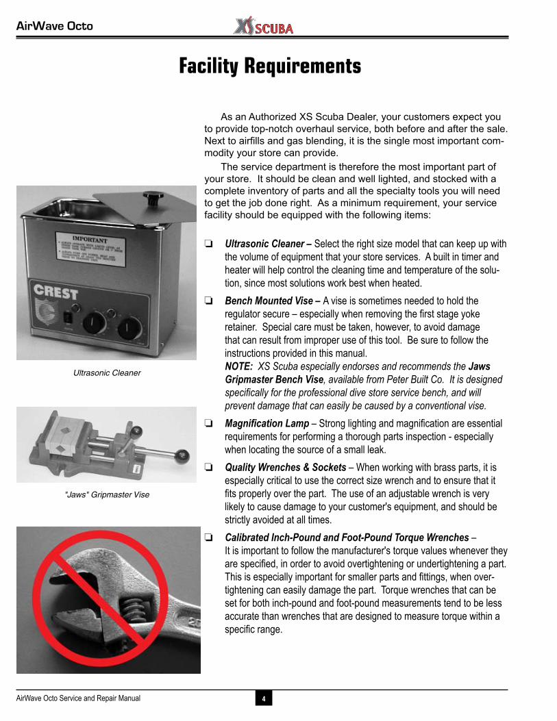
❏ Ultrasonic Cleaner – Select the right size model that can keep up with the volume of equipment that your store services. A built in timer and heater will help control the cleaning time and temperature of the solu-tion, since most solutions work best when heated.
❏ Bench Mounted Vise – A vise is sometimes needed to hold the regulator secure – especially when removing the first stage yoke retainer. Special care must be taken, however, to avoid damage that can result from improper use of this tool. Be sure to follow the instructions provided in this manual. NOTE: XS Scuba especially endorses and recommends the Jaws Gripmaster Bench Vise, available from Peter Built Co. It is designed specifically for the professional dive store service bench, and will prevent damage that can easily be caused by a conventional vise.
❏ Magnification Lamp – Strong lighting and magnification are essential requirements for performing a thorough parts inspection - especially when locating the source of a small leak.
❏ Quality Wrenches & Sockets – When working with brass parts, it is especially critical to use the correct size wrench and to ensure that it fits properly over the part. The use of an adjustable wrench is very likely to cause damage to your customer's equipment, and should be strictly avoided at all times.
❏ Calibrated Inch-Pound and Foot-Pound Torque Wrenches – It is important to follow the manufacturer's torque values whenever they are specified, in order to avoid overtightening or undertightening a part. This is especially important for smaller parts and fittings, when over-tightening can easily damage the part. Torque wrenches that can be set for both inch-pound and foot-pound measurements tend to be less accurate than wrenches that are designed to measure torque within a specific range.
Service & Repair Manual
5 Copyright ©2008 XS Scuba
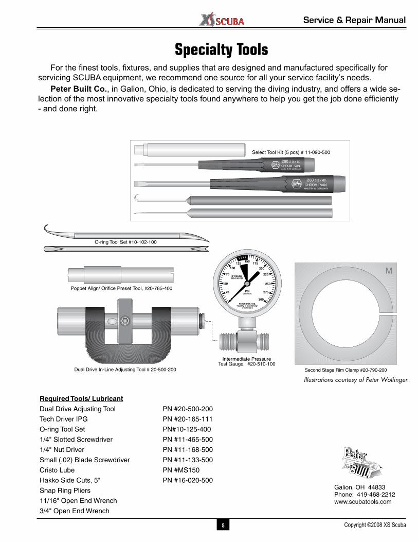
Specialty ToolsFor the finest tools, fixtures, and supplies that are designed and manufactured specifically for
servicing SCUBA equipment, we recommend one source for all your service facility’s needs.Peter Built Co., in Galion, Ohio, is dedicated to serving the diving industry, and offers a wide se-
lection of the most innovative specialty tools found anywhere to help you get the job done efficiently - and done right.
Illustrations courtesy of Peter Wolfinger.
Galion, OH 44833Phone: 419-468-2212www.scubatools.com
Required Tools/ Lubricant
Dual Drive Adjusting Tool PN #20-500-200
Tech Driver IPG PN #20-165-111
O-ring Tool Set PN#10-125-400
1/4" Slotted Screwdriver PN #11-465-500
1/4" Nut Driver PN #11-168-500
Small (.02) Blade Screwdriver PN #11-133-500
Cristo Lube PN #MS150
Hakko Side Cuts, 5" PN #16-020-500
Snap Ring Pliers
11/16" Open End Wrench
3/4" Open End Wrench
100
200
80
60
40
20 180
160
120IP RANGE
125-150 PSI
PSI
PETER BUILT"Quality in the making"
(419) 468-2212
USE NO OIL
140
25
50
150125
100
75
175
200
225
250
275
3000
IP RANGE125-150 PSI
PSIUSE NO OIL
PETER BUILT CO."Quality in the making"
(419) 468-2212
260 3.5 x 60
260 2.0 x 50
Select Tool Kit (5 pcs) # 11-090-500
Poppet Align/ Orifice Preset Tool, #20-785-400
Intermediate Pressure Test Gauge, #20-510-100
O-ring Tool Set #10-102-100
Dual Drive In-Line Adjusting Tool # 20-500-200 Second Stage Rim Clamp #20-790-200
M
AirWave Octo
6AirWave Octo Service and Repair Manual
Preliminary Inspection
External Inspection
1. Closely examine the conical filter to check for any signs that contaminants have entered the system, including sea water, rust, or aluminum oxide.
NOTE: A green discoloration of the filter indicates that moisture has entered the regulator, and internal corro-sion has possibly occurred. Other types of discoloration may indicate that the regulator has been used with a corroded cylinder. Advise the customer of this, and the possible need to obtain service for the cylinder.
2. Slide back the hose protectors, if present, to visually inspect the condition of the hoses, especially at their fit-tings.
3. Closely examine the finish of the first stage to check for any chips, scratches, or other damage that exposes the brass beneath the finish.
CAUTION: Do not clean any parts that show damage to their finish inside an ultrasonic cleaner.
4. Closely examine all parts of the first stage for any other signs of external corrosion.
Immersion / Leak Test1. Check to ensure that the regulator is fully assembled and
connected to a second stage, and that there are no open ports or hoses. Connect the first stage to a cylinder that is filled with 3,000 psi, and open the cylinder valve to pressurize the regulator.
2. If leakage cannot be heard, or if the source of leakage detected audibly is not obvious, immerse the first stage in fresh water to check further for any signs of air leakage, especially at the fittings of hoses.
3. Note the source of any leakage found and refer to the Troubleshooting Guide to determine its possible cause.
4. Close the cylinder valve and depress the second stage purge button to depressurize the regulator before per-forming the next procedure.
2SE
CTI
ON

Service & Repair Manual
7 Copyright ©2008 XS Scuba
Intermediate Pressure Test
NOTE: It is not necessary to perform this test unless a problem has been reported that requires diagnostic troubleshooting and repair. When performing routine overhaul service, proceed directly to the following sec-tion, Disassembly.
1. Connect a calibrated intermediate pressure test gauge to the regulator, either with a quick-disconnect inflator hose or with the female fitting of a second stage LP hose, depending on the connection of the test gauge.
CAUTION: To provide a safety relief valve in the event that intermediate pressure exceeds 155-170 psi, ensure that a fully assembled and properly adjusted second stage is connected to the first stage before pressurizing. Failure to relieve intermediate pressure that exceeds 400 psi may result in damage or rupture of the test gauge or LP hose, and could cause serious personal injury.
2. Slowly open the supply valve to pressurize the first stage. Closely monitor the IP test gauge to determine whether the intermediate pressure rises above 145 psi.
3. Note the intermediate pressure indicated by the test gauge, and purge the second stage several times to determine whether lockup is achieved without creeping or fluctuating back and forth.
4. If the intermediate pressure creeps up or otherwise fluc-tuates after cycling the regulator, wait for it to stabilize (if possible) before making a final note of the intermediate pressure.
NOTE: Correct intermediate pressure for the first stage is 140 (±5) psi, with an inlet pressure between 2,500 - 3,000 psi.
5. Close the supply valve and depress the second stage purge button to depressurize the system before attempt-ing to perform any disassembly.
▼ After completing the Preliminary Inspection, proceed to Section 3 – Disassembly
AirWave Octo
8AirWave Octo Service and Repair Manual
Disassembly Procedures
General Guidelines
▼ Prior to performing any disassembly, check to ensure that the service facility is well equipped with all the tools and parts needed to perform a complete service from start to finish. DO NOT attempt to perform the service unless all of the required tools and parts are available.
▼ All o-rings are classified as being either dynamic or static. Dynamic o-rings are those which sustain friction and movement, as they are either mounted directly onto a moving part, or create a seal against a moving part. Static o-rings simply create a seal between two non-moving parts, and are therefore less subject to wear than dynamic o-rings. After passing close inspection, static O-rings may sometimes be reused, although this is not necessarily recommended. Dynamic O-rings must be automatically discarded and replaced with every service, regardless of age or appearance.
▼ Refer to the schematic and parts list while performing these procedures. Each part is identified by its reference number shown on the drawing the first time it is referred to in the procedure.
▼ Do not attempt to reuse parts that are designated to be automatically discarded and replaced with the parts provided in the overhaul parts kit. These parts should be shown to the customer, however, to ensure their confi-dence and satisfaction that complete overhaul service has been performed.
▼ Inspect all reusable parts as directed, either during or im-mediately following the disassembly procedures. When in doubt, compare the part with one that is new to best determine its condition.
3SE
CTI
ON
Service & Repair Manual
9 Copyright ©2008 XS Scuba
Second Stage DisassemblyCAUTION: Whenever possible, use only plastic or brass O-ring tools for removing O-rings in order to pre-vent damage to the sealing surface. Steel instruments, such as dental picks, can easily damage the sealing surface of a softer brass part, causing irreparable leak-age and requiring the part to be replaced with new.
1. Slide back the hose cover to expose the connection of the LP hose.
2. While holding the inlet fitting(7) secure with a n" open-end wrench, apply a n" open-end wrench to the fitting of the LP hose. Turn the hose fitting counter-clockwise to loosen and remove.
3. Using a plastic or brass O-ring tool, carefully remove the O-ring from the post inside the hose fitting.
CAUTION: When performing the above step, be very careful to avoid scratching the O-ring sealing surface. Doing so may cause a permanent leak that will require the replacement of the LP hose.
4. Using a n" open end wrench, turn the inlet fitting counter-clockwise to loosen, and unscrew it completely by hand to remove. Closely examine the plastic threads and overall condition of the inlet fitting, and replace with new if any damage is found.
5. Snip the plastic tie-strap(12) that holds the mouth-piece(11), and gently pull the mouthpiece off the second stage housing(13). Inspect the mouthpiece to ensure that it is supple and free of any tears or corrosion. If any dam-age is found that could result in discomfort or leakage, discard the mouthpiece and do not reuse.
6. While holding the second stage secure with one hand, firmly grasp the retaining ring(1) with the other, and turn the ring counter-clockwise to loosen and remove it, along with the diaphragm cover(2).
NOTE: If the retaining ring is difficult to loosen, XS Scuba recommends using the Rim Clamp (P/N 20-790-200), available from Peter Built Co. Complete instructions are provided with the tool.
7. Separate the diaphragm cover from the retaining ring, and closely inspect the cover to ensure that it is perfectly round and free of damage. If any damage is found, dis-card the cover and replace with new.
AirWave Octo
10AirWave Octo Service and Repair Manual
8. Lift out the diaphragm(4) and thrust washer(3) from the second stage housing. Inspect the diaphragm to ensure that it is supple and free of any pinholes, tears, corrosion, or other damage. If any damage is found, discard it and replace with new.
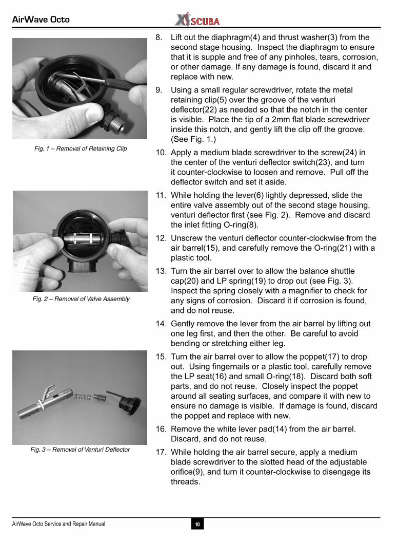
9. Using a small regular screwdriver, rotate the metal retaining clip(5) over the groove of the venturi deflector(22) as needed so that the notch in the center is visible. Place the tip of a 2mm flat blade screwdriver inside this notch, and gently lift the clip off the groove. (See Fig. 1.)
10. Apply a medium blade screwdriver to the screw(24) in the center of the venturi deflector switch(23), and turn it counter-clockwise to loosen and remove. Pull off the deflector switch and set it aside.
11. While holding the lever(6) lightly depressed, slide the entire valve assembly out of the second stage housing, venturi deflector first (see Fig. 2). Remove and discard the inlet fitting O-ring(8).
12. Unscrew the venturi deflector counter-clockwise from the air barrel(15), and carefully remove the O-ring(21) with a plastic tool.
13. Turn the air barrel over to allow the balance shuttle cap(20) and LP spring(19) to drop out (see Fig. 3). Inspect the spring closely with a magnifier to check for any signs of corrosion. Discard it if corrosion is found, and do not reuse.
14. Gently remove the lever from the air barrel by lifting out one leg first, and then the other. Be careful to avoid bending or stretching either leg.
15. Turn the air barrel over to allow the poppet(17) to drop out. Using fingernails or a plastic tool, carefully remove the LP seat(16) and small O-ring(18). Discard both soft parts, and do not reuse. Closely inspect the poppet around all seating surfaces, and compare it with new to ensure no damage is visible. If damage is found, discard the poppet and replace with new.
16. Remove the white lever pad(14) from the air barrel. Discard, and do not reuse.
17. While holding the air barrel secure, apply a medium blade screwdriver to the slotted head of the adjustable orifice(9), and turn it counter-clockwise to disengage its threads.
Fig. 1 – Removal of Retaining Clip
Fig. 3 – Removal of Venturi Deflector
Fig. 2 – Removal of Valve Assembly
Service & Repair Manual
11 Copyright ©2008 XS Scuba
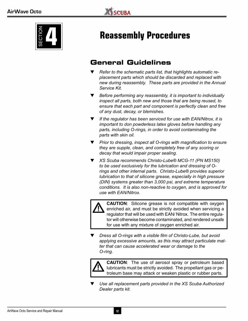
Fig. 5 – Orifice Inspection
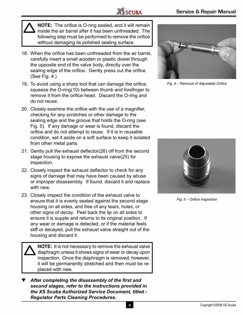
NOTE: The orifice is O-ring sealed, and it will remain inside the air barrel after it has been unthreaded. The following step must be performed to remove the orifice without damaging its polished sealing surface.
18. When the orifice has been unthreaded from the air barrel, carefully insert a small wooden or plastic dowel through the opposite end of the valve body, directly over the sealing edge of the orifice. Gently press out the orifice. (See Fig. 4.)
19. To avoid using a sharp tool that can damage the orifice, squeeze the O-ring(10) between thumb and forefinger to remove it from the orifice head. Discard the O-ring and do not reuse.
20. Closely examine the orifice with the use of a magnifier, checking for any scratches or other damage to the sealing edge and the groove that holds the O-ring (see Fig. 5). If any damage or wear is found, discard the orifice and do not attempt to reuse. If it is in reusable condition, set it aside on a soft surface to keep it isolated from other metal parts.
21. Gently pull the exhaust deflector(26) off from the second stage housing to expose the exhaust valve(25) for inspection.
22. Closely inspect the exhaust deflector to check for any signs of damage that may have been caused by abuse or improper disassembly. If found, discard it and replace with new,
23. Closely inspect the condition of the exhaust valve to ensure that it is evenly seated against the second stage housing on all sides, and free of any tears, holes, or other signs of decay. Peel back the lip on all sides to ensure it is supple and returns to its original position. If any wear or damage is detected, or if the material feels stiff or decayed, pull the exhaust valve straight out of the housing and discard it.
NOTE: It is not necessary to remove the exhaust valve diaphragm unless it shows signs of wear or decay upon inspection. Once the diaphragm is removed, however, it will be permanently stretched and then must be re-placed with new.
▼ After completing the disassembly of the first and second stages, refer to the instructions provided in the XS Scuba Authorized Service Document, titled - Regulator Parts Cleaning Procedures.
Fig. 4 – Removal of Adjustable Orifice
AirWave Octo
12AirWave Octo Service and Repair Manual
General Guidelines▼ Refer to the schematic parts list, that highlights automatic re-
placement parts which should be discarded and replaced with new during reassembly. These parts are provided in the Annual Service Kit.
▼ Before performing any reassembly, it is important to individually inspect all parts, both new and those that are being reused, to ensure that each part and component is perfectly clean and free of any dust, decay, or blemishes.
▼ If the regulator has been serviced for use with EAN/Nitrox, it is important to don powderless latex gloves before handling any parts, including O-rings, in order to avoid contaminating the parts with skin oil.
▼ Prior to dressing, inspect all O-rings with magnification to ensure they are supple, clean, and completely free of any scoring or decay that would impair proper sealing.
▼ XS Scuba recommends Christo-Lube® MCG-11 (PN MS150) to be used exclusively for the lubrication and dressing of O-rings and other internal parts. Christo-Lube® provides superior lubrication to that of silicone grease, especially in high pressure (DIN) systems greater than 3,000 psi, and extreme temperature conditions. It is also non-reactive to oxygen, and is approved for use with EAN/Nitrox.
CAUTION: Silicone grease is not compatible with oxygen enriched air, and must be strictly avoided when servicing a regulator that will be used with EAN/ Nitrox. The entire regula-tor will otherwise become contaminated, and rendered unsafe for use with any mixture of oxygen enriched air.
▼ Dress all O-rings with a visible film of Christo-Lube, but avoid applying excessive amounts, as this may attract particulate mat-ter that can cause accelerated wear or damage to the O-ring.
CAUTION: The use of aerosol spray or petroleum based lubricants must be strictly avoided. The propellant gas or pe-troleum base may attack or weaken plastic or rubber parts.
▼ Use all replacement parts provided in the XS Scuba Authorized Dealer parts kit.
Reassembly Procedures4SE
CTI
ON

Service & Repair Manual
13 Copyright ©2008 XS Scuba
Second Stage ReassemblyWARNING: DO NOT attempt to use any other manu-facturer's part as a substitute for any XS Scuba part, regardless of any similarity in shape, size, or appear-ance. Doing so may render the product unsafe, and could result in serious injury or death.
1. Install the exhaust valve(25), if it was removed, into the second stage housing(13) by gently pulling the stem through the hole in the center of the sealing area, until the barb has passed through and is securely seated against the opposite side.
2. Mate two seating tabs on one side of the exhaust deflec-tor(26) into two slots inside the inner groove of the sec-ond stage housing, and then press the opposite side until it snaps securely into place.
3. Closely examine both sides of the white lever pad(14) to identify that the mounting tabs on both legs are rounded on one side and flat on the other. (See Fig. 6.) Hold the air barrel with the flat cut facing up, and place the clip over the tube with the rounded side facing toward the flange, so that one tab engages in the hole next to it. Then, gently press the opposite leg into place so the the other tab engages in the opposite hole. When done cor-rectly, the lever pad should rest flush against the flange, with both tabs securely seated. (See Fig. 7.)
CAUTION: Do not stretch the legs of the plastic retain-ing clip, or attempt to install it if damage or breakage has occurred.
4. Insert the stem of the LP seat(16) into the large end of the poppet(17). DO NOT use adhesive.
5. Lubricate and install the small O-ring(18) over the groove on the opposite end of the poppet, being careful to avoid stretching it excessively. Examine the poppet's features to determine proper positioning. (See Fig. 8.)
6. While holding the air barrel with the flat cut facing straight down, guide the poppet into the tube, LP seat first, with the ears facing straight down. (See Fig. 9.)
NOTE: To better control the orientation of the poppet inside the air barrel while the lever is being installed, XS Scuba recommends using the Poppet Align/ Orifice Preset Tool (P/N 20-785-400), available from Peter Built Co. (See Fig. 10.)
Fig. 7 – Air barrel Orientation
Fig. 6 – Lever Pad Features
Fig. 9 – Correct Poppet Orientation
Fig. 8 – Poppet Features
Fig. 11 – Correct Venturi Deflector Orientation
Fig. 10 – Poppet Alignment/ Preset Tool

AirWave Octo
14AirWave Octo Service and Repair Manual
7. Apply a light coat of lubricant to both ends of the poppet spring(4), and place the spring over the small end of the poppet, inside the air barrel. Be careful not to disturb the the orientation of the poppet inside the air barrel.
8. Insert the small end of the shuttle cap(20) into the end of the poppet spring.
9. Install the O-ring(21) onto the groove of the venturi de-flector(22). Mate the deflector directly over the shuttle cap, and screw it clockwise by hand onto the air barrel until it stops. Then, turn it back one full turn counter-clockwise until the deflector vane is resting directly over the flat cut of the air barrel (see Fig. 11.).
10. Closely examine both holes where the lever pad is in-stalled, to ensure that the ears of the poppet are properly aligned as shown (see Fig. 12). While holding the air barrel with the flat cut facing down, insert one leg of the lever(6) into one hole, so that it engages with the poppet (see Fig. 13). Being careful to avoid stretching or bend-ing the lever, rotate it over the air barrel until the opposite leg engages with the opposite side. The lever should now be standing up when released, pointing toward the venturi deflector. (See Fig. 14.)
11. While holding the second stage housing right side up with the mouthpiece tube facing you, slide the valve assembly into the opening in the right side of the housing. Gently depress the lever, and then slide the valve assembly fully into place so that the lever pad is seated flush. (See Fig. 15.)
12. Install the retaining clip(5) over the groove of the venturi deflector inside the housing, so that it snaps securely into place. (See Fig. 16.)
13. Install the O-ring(8) over the threaded inlet of the air bar-rel, being careful to avoid stretching it or rolling over the threads. Use a smooth instrument to ensure that it is seated at the base of the threads, against the wall of the housing.
14. Mate the inlet fitting(7) over the threads of the air barrel, and turn it clockwise by hand until finger snug. Apply a n" open end wrench to tighten it further by exactly 8 turn.
CAUTION: Be careful to avoid overtightening the inlet fitting, which can crack if it is overtightened, requiring its replacement.
Fig. 13 – Lever Installation
Fig. 14 – Correct Lever Orientation
Fig. 12 – Poppet Correcty Installed
Fig. 15 – Valve Assembly Completely Installed
Fig. 16 – Installing Retaining Clip
Service & Repair Manual
15 Copyright ©2008 XS Scuba
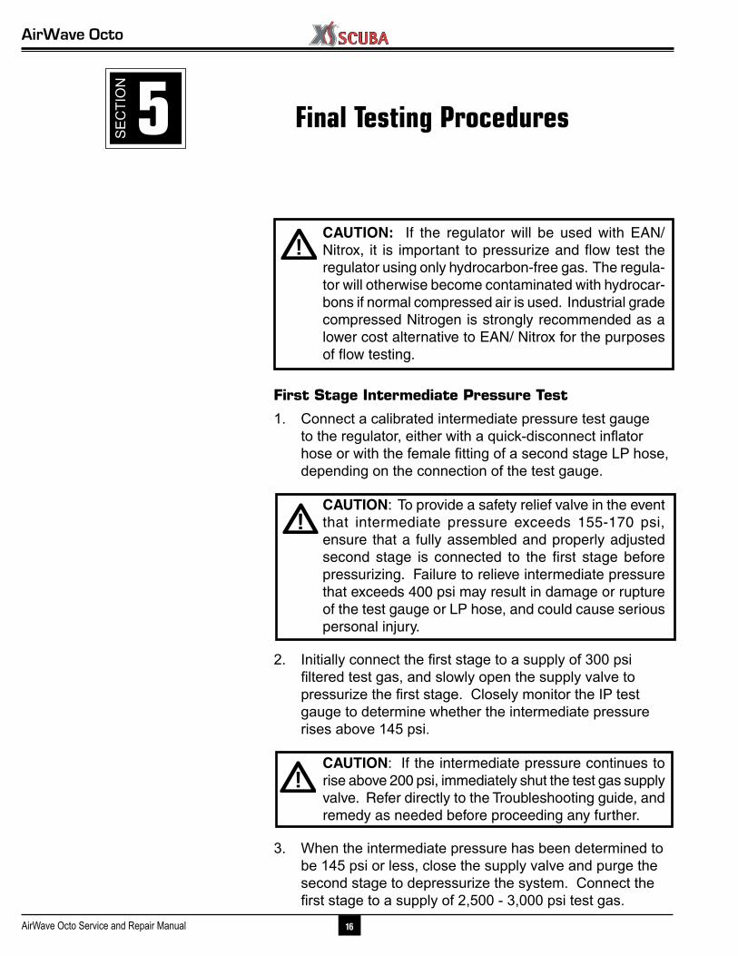
15. Install the O-ring(10) onto the head of the adjustable orifice(9) and carefully insert the orifice into the inlet of the air barrel with the polished cone facing in. Using a small wooden or plastic down, press the orifice in so that it rests against the threads inside the air barrel. (See Fig. 17.)
16. While holding the retaining clip stationary, apply a wide blade screwdriver to turn the venturi deflector counter-clockwise until a) it is perfectly flush with the outer surface of the housing, b) the deflector vane is resting directly over the outlet port of the air barrel, and c) the slots are straightly aligned. (See Fig. 18.)
17. Fit the deflector switch(23) onto the venturi deflector so that the knob is seated against the forward stop. (See Fig. 19.)
18. Mate the screw(24) into the outer center of the deflector switch, and apply a medium blade screwdriver to turn it clockwise until snug. Do not overtighten.
19. Apply a medium blade screwdriver to the slotted head of the orifice inside the air barrel, and turn it clockwise while closely watching the lever. When the lever starts to drop, stop – do not turn the orifice any further. This will indicate that the orifice has made contact against the LP seat. (See Fig. 20.)
20. Lay the diaphragm(4) inside the housing, directly over the lever with its raised surface facing up, and then the thrust washer(3).
21. Fit the diaphragm cover(2) inside the housing so that it seats directly over the diaphragm. Turn it as needed to align the logo straight between the inlet and adjustment knob.
22. Mate the retaining ring(1) over the diaphragm cover and into the housing, and turn it clockwise to engage the threads. While holding the front cover secure with one hand, tighten the retaining ring until snug with the other. Be careful to avoid over-tightening.
23 Install the mouthpiece(11) onto the housing, correctly ori-ented with the top facing up. Fasten a tie-strap(12) over the mouthpiece with the locking tab facing toward the inlet coupling, and cinch it snug. Trim the excess material close to the locking tab.
▼ After completing the reassembly of the second stage, proceed to Section 5 – Final Testing
Fig. 19 – Correct Position of Venturi Switch
Fig. 17 – Installation of Orifice
Fig. 20 – Preliminary Orifice Setting
Fig. 18 – Venturi Deflector Set Flush
AirWave Octo
16AirWave Octo Service and Repair Manual
Final Testing Procedures
CAUTION: If the regulator will be used with EAN/ Nitrox, it is important to pressurize and flow test the regulator using only hydrocarbon-free gas. The regula-tor will otherwise become contaminated with hydrocar-bons if normal compressed air is used. Industrial grade compressed Nitrogen is strongly recommended as a lower cost alternative to EAN/ Nitrox for the purposes of flow testing.
First Stage Intermediate Pressure Test
1. Connect a calibrated intermediate pressure test gauge to the regulator, either with a quick-disconnect inflator hose or with the female fitting of a second stage LP hose, depending on the connection of the test gauge.
CAUTION: To provide a safety relief valve in the event that intermediate pressure exceeds 155-170 psi, ensure that a fully assembled and properly adjusted second stage is connected to the first stage before pressurizing. Failure to relieve intermediate pressure that exceeds 400 psi may result in damage or rupture of the test gauge or LP hose, and could cause serious personal injury.
2. Initially connect the first stage to a supply of 300 psi filtered test gas, and slowly open the supply valve to pressurize the first stage. Closely monitor the IP test gauge to determine whether the intermediate pressure rises above 145 psi.
CAUTION: If the intermediate pressure continues to rise above 200 psi, immediately shut the test gas supply valve. Refer directly to the Troubleshooting guide, and remedy as needed before proceeding any further.
3. When the intermediate pressure has been determined to be 145 psi or less, close the supply valve and purge the second stage to depressurize the system. Connect the first stage to a supply of 2,500 - 3,000 psi test gas.
5SE
CTI
ON
Service & Repair Manual
17 Copyright ©2008 XS Scuba
NOTE: Correct intermediate pressure for the first stage is between 135-145 psi, with a supply pressure of 2,500 - 3000 psi.
4. Open the supply valve again while monitoring the IP test gauge to ensure that the intermediate pressure does not rise above 145 psi. If the intermediate pressure rises above 145 psi, immediately close the supply valve and purge the system. Refer to the Troubleshooting Guide, and remedy as needed before proceeding.
5. Repeatedly purge the second-stage approximately 15-20 times to cycle the regulator. Then, check the test gauge to determine whether the intermediate pressure locks up consistently after each cycle and remains stable at 140 (±5) psi, with no signs of creeping or fluctuation. If the intermediate pressure is not within the specified range, or if it fails to lock up with no creep, refer to the Troubleshooting Guideto determine the cause of the problem. Repeat this procedure after it is corrected.
Second Stage Adjustment and Flow Test
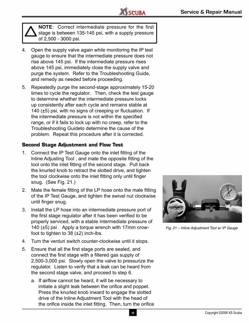
1. Connect the IP Test Gauge onto the inlet fitting of the Inline Adjusting Tool , and mate the opposite fitting of the tool onto the inlet fitting of the second stage. Pull back the knurled knob to retract the slotted drive, and tighten the tool clockwise onto the inlet fitting only until finger snug. (See Fig. 21.)
2. Mate the female fitting of the LP hose onto the male fitting of the IP Test Gauge, and tighten the swivel nut clockwise until finger snug.
3. Install the LP hose into an intermediate pressure port of the first stage regulator after it has been verified to be properly serviced, with a stable intermediate pressure of 140 (±5) psi . Apply a torque wrench with 17mm crow-foot to tighten to 38 (±2) inch-lbs.
4. Turn the venturi switch counter-clockwise until it stops.5. Ensure that all the first stage ports are sealed, and
connect the first stage with a filtered gas supply of 2,500-3,000 psi. Slowly open the valve to pressurize the regulator. Listen to verify that a leak can be heard from the second stage valve, and proceed to step 6.a. If airflow cannot be heard, it will be necessary to
initiate a slight leak between the orifice and poppet. Press the knurled knob inward to engage the slotted drive of the Inline Adjustment Tool with the head of the orifice inside the inlet fitting. Then, turn the orifice
Fig. 21 – Inline Adjustment Tool w/ IP Gauge
AirWave Octo
18AirWave Octo Service and Repair Manual
slightly counter-clockwise while lightly depressing the purge cover to prevent wear on the seat. Do not adjust any further than is needed to establish a slight leak.
6. Hold the drive of the Inline Adjustment Tool engaged with the orifice. While lightly depressing the purge cover, turn the orifice slightly clockwise a very small fraction of a turn. Pause after each adjustment to listen, and be careful to avoid over-adjusting beyond the point that the leak has stopped. When the leak has stopped, purge the second stage again to ensure that it does not return. Observe the IP Test Gauge while purging to verify that it indicates a stable intermediate pressure after each cycle, with no creep or fluctuation.
CAUTION: Over-adjustment of the orifice can cause excessive spring load in the second stage valve, and may impair the regulator’s performance.
8. When the second stage is properly adjusted with no leaks or lever slack, depressurize and purge the system to dis-connect the LP hose.
9. Reconnect the LP hose to the inlet coupling, and apply a torque wrench with 17mm crow-foot to tighten the fitting to a torque measurement of 55 inch-lbs (±5).
Subjective Breathing Test
1. Connect the regulator to a cylinder containing 2,500 – 3,000 psi, and open the valve to pressurize the system.
2. Turn the venturi switch counter-clockwise to the open or "dive" position.
3. Fully depress the second stage purge to ensure that an adequate volume of air flows through the mouthpiece, sufficient to clear the second stage. Then, breathe sev-eral times from the second stage.
A properly serviced and adjusted regulator should de-liver air upon deep inhalation without excessive inhala-tion effort, freeflow, or vibration. When exhaling, there should be no resistance or sticking of the exhalation valve. If any of these problems occur, refer to Table 2 - Troubleshooting.
Service & Repair Manual
19 Copyright ©2008 XS Scuba
Flowbench Testing (optional)
The Subjective Breathing Test, combined with the Inter-mediate Pressure Test, will sufficiently verify the regulator's performance in most circumstances. As an additional test, a Magnahelic flowbench can be used to verify the opening effort, which should not exceed 1.5 – 2.0 column inches H2O with the venturi switch turned counter-clockwise to the open or "dive" position.
External Leak Test
After first stage reassembly and final adjustment of the second stage has been completed, submerge the entire regulator in a test tank of clean water while pressurized with 2,500-3000 psi. Observe any bubbles arising from the submerged regulator over a one minute period. The recom-mended time is necessary due to slower bubble formation that occurs in smaller leaks. Disassemble the regulator at the source of the leak to check sealing surfaces, assembly sequence and component positioning in order to correct the problem(s).
NOTE: The location of extremely small leaks can best be detected by applying a soap solution to the leak area. Before disassembling to correct any leaks, rinse the entire regulator thoroughly with fresh water and blow out all residual moisture with filtered, low-pressure (25 psi) test gas. Refer to the Troubleshooting Guide.
▼ When the second stage has been adjusted and tested according to the prescribed procedures, close the cylinder valve completely and purge the second stage to depres-surize the system. Loosen the yoke screw to remove the first stage from the cylinder, and seal the dust cap over the inlet. Disinfect the mouthpiece, and dry the regulator completely with a clean towel. This completes the over-haul service procedures for the AirWave regulator.

AirWave Octo
20AirWave Octo Service and Repair Manual
1. Excessive intermediate pressure. 1. Refer to first stage troubleshooting 2. Damaged or worn LP seat. 2. Replace with new. 3. Damaged orifice sealing surface. 3. Replace with new. 4. Damaged orifice O-ring. 4. Replace with new. 5. Orifice incorrectly adjusted. 5. Reset to preliminary setting and readjust. 6. Poppet spring damaged. 6. Replace with new.
1. Insufficent intermediate pressure. 1. Refer to first stage troubleshooting 2. Orifice incorrectly adjusted. 2. Reset to preliminary setting and readjust. 3. Lever is damaged. 3. Replace with new.
1. Lever is slack, or orifice incorrectly adjusted. 1. Reset to preliminary settings and readjust.
2. Lever is bent. 2. Replace with new.
1. Exhaust valve worn or damaged. 1. Replace with new. 2. Mouthpiece worn or damaged. 2. Replace with new.
Symptom poSSible CauSe treatment
Freeflow or leakage
Excessive Inhalation Resistanceor Hesitation
Insufficient airflow when purge is depressed
Troubleshooting Guide
Second Stage
Water entering second stage

Service & Repair Manual
21 Copyright ©2008 XS Scuba
Schematic & Parts List
AirWave Second Stage1
2
3
4
1918
17
16
9 10
15
14
11
12
8
13
7
56
23 24
25
26
22
2120
28
2927
RK2 7.00 - Overhaul Service Kit
1 .......RP320-01 1 Retaining Ring 2 .......RP320-02 1 Purge Cover 3 .......RP320-03 1 Thrust Washer 4 .......RP320-04 1 Diaphragm 5 .......RP320-05 1 Retaining Clip 6 .......RP320-06 1 Lever 7 .......RP320-07 1 Inlet Fitting 8 .......RP320-08 1 O-ring 9 .......RP320-09 1 Adjustable Orifice 10 ......RP320-10 1 O-ring 11 ......RP320-11 1 Mouthpiece 12 ......RP320-12 1 Tie Strap 13 ......RP320-13 1 Housing 14 ......RP320-14 1 Lever Pad 15 ......RP320-15 1 Air Barrel
16 ......RP320-16 1 LP Seat 17 ......RP320-17 1 Poppet 18 ......RP320-18 1 O-ring 19 ......RP320-19 1 LP Spring 20 ......RP320-20 1 Balance Shuttle Cap 21 ......RP320-21 1 O-ring 22 ......RP320-22 1 Venturi Switch 23 ......RP320-23 1 Venturi Knob 24 ......RP320-24 1 Screw 25 ......RP320-25 1 Exhaust Valve Diaphragm 26 ......RP320-26 1 Exhaust Grill 27 ......RP320-27 1 O-ring 28 ...... LP36 1 LP Hose, 36" 29 ......RP320-29 1 O-ring
Ref # PN Price Qty Description Ref # PN Price Qty Description
* Bold Indicates Overhaul Replacement Part - Provided In Parts Kit #RK2