service trainning school - white's inc. wrapper service manual.pdf · product range overview...
TRANSCRIPT

Service Trainning School
Single Bale Wrapper
Feb 15-17 2011

Outline
• About us
• Product Range Overview
• Getting Started and Setting
• Operation
• Adjustments &Trouble Shooting
• Maintenance
• Check list (before machine delivery)
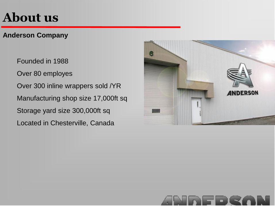
About us
Anderson Company
Founded in 1988
Over 80 employes
Over 300 inline wrappers sold /YR
Manufacturing shop size 17,000ft sq
Storage yard size 300,000ft sq
Located in Chesterville, Canada

About us
Anderson Network
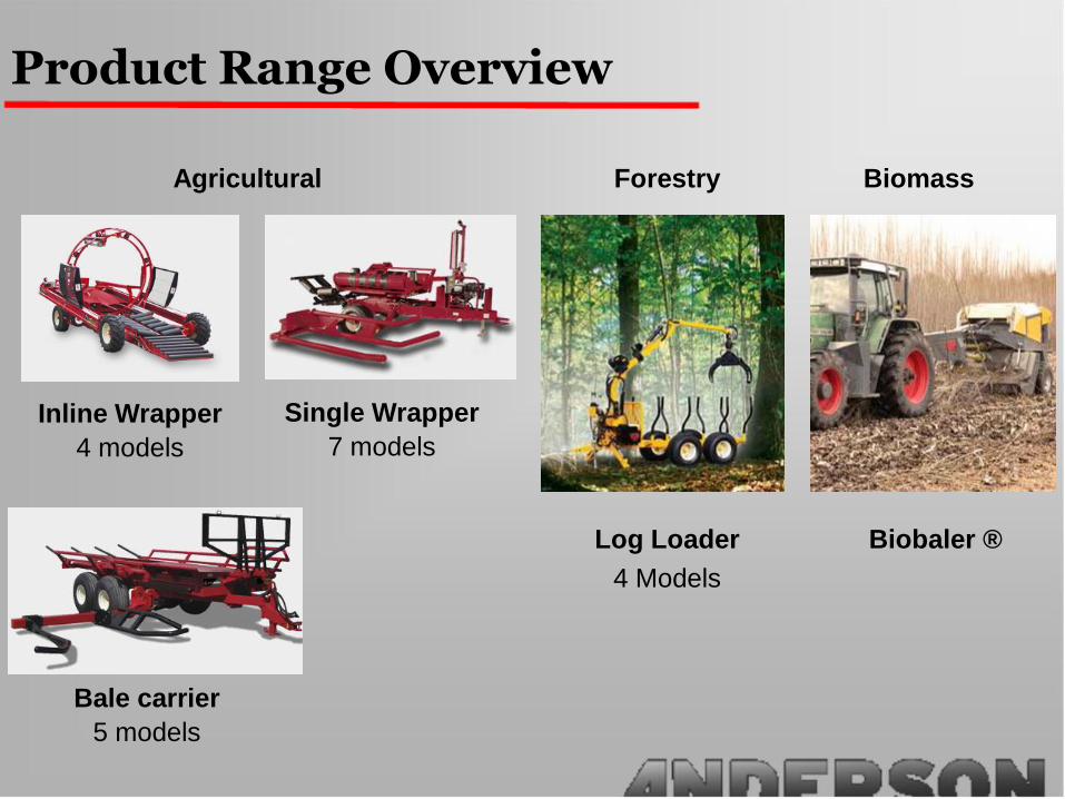
Product Range Overview
Agricultural Forestry Biomass
Biobaler ®Log Loader
4 Models
Inline Wrapper
4 models
Single Wrapper
7 models
Bale carrier
5 models
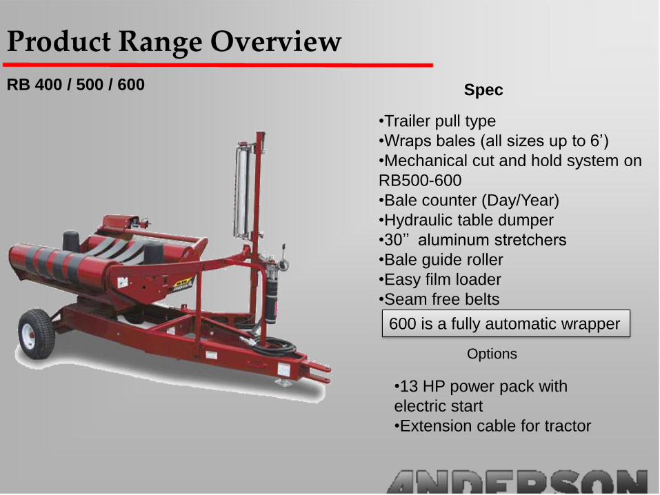
Product Range Overview
RB 400 / 500 / 600 Spec
•Trailer pull type
•Wraps bales (all sizes up to 6’)
•Mechanical cut and hold system on
RB500-600
•Bale counter (Day/Year)
•Hydraulic table dumper
•30’’ aluminum stretchers
•Bale guide roller
•Easy film loader
•Seam free belts
Options
•13 HP power pack with
electric start
•Extension cable for tractor
600 is a fully automatic wrapper

Product Range Overview
RB 580/680
Spec
Options
•Trailer pull type
•Wraps bales (all sizes up to 6’)
•Fully automatic with hand-held remote (680)
•13HP power pack with electric start
•Bale Counter (Day/Year)
•Hydraulic cut and hold plastic system
•30’’ aluminum stretcher
•Bale guide roller
•Easy plastic film loader
•Seam free belts
•Regular bale dumper
•3 position bale dumper
•Front and rear stabilizers
•Self loading arm
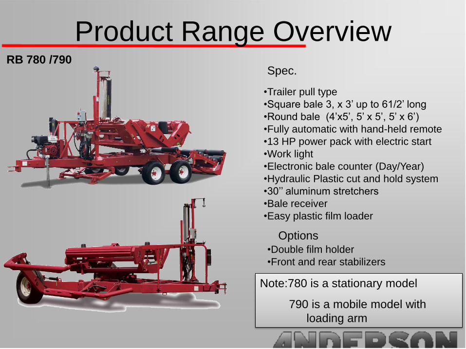
Product Range OverviewRB 780 /790
Spec.
Options
•Trailer pull type
•Square bale 3, x 3’ up to 61/2’ long
•Round bale (4’x5’, 5’ x 5’, 5’ x 6’)
•Fully automatic with hand-held remote
•13 HP power pack with electric start
•Work light
•Electronic bale counter (Day/Year)
•Hydraulic Plastic cut and hold system
•30’’ aluminum stretchers
•Bale receiver
•Easy plastic film loader
•Double film holder
•Front and rear stabilizers
Note:780 is a stationary model
790 is a mobile model with
loading arm
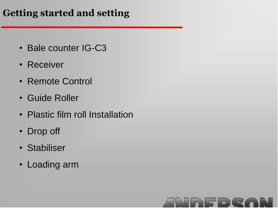
Getting started and setting
• Bale counter IG-C3
• Receiver
• Remote Control
• Guide Roller
• Plastic film roll Installation
• Drop off
• Stabiliser
• Loading arm

(Program menus)Menu #1 (adjustment of turns / plastic layers)
In this menu you can adjust the number of turns that the
wrapper makes in each cycle. We recommend 17 turns which
will give you approximately 4 layers of plastic on the wrapped
bale.
Menu #2
To get to the menu you press the Adjust. Select button.
This menu is to change the daily bales. By pressing up and
down you can change this number.
Menu #3
By pressing the Adjust. Select button you will arrive at this
menu.
The menu shows the bales wrapped yearly. You can reset this
by using the + / - buttons.
Menu #4
By pressing the Adjust. Select button for the 4th time you will
arrive at this menu. This menu is for changing the language.
By pressing the Adjust. Select button one more time you will go
to the first menu again.
Note: When you wrap bales (after you have preset the number of turns that you will be putting on each bale)
manually with the levers and you are close to having the number of turns the bale counter will beep three times.
At this point you will bring the table to its dumping position (Center of the table will be aligned with the axle) and
dump the table. If you have a model 400 you will have to cut the plastic before you dump.
Bale counter IG-03 400 / 500 / 580
Getting Started

Antenna
Emergency Stop /
Start button
Align / Wrap
Blinking fast : Error
Blinking slowly: Wrapping
Continuous: Ready
Manual Controls
Receiver 600 / 680 / 780 / 790
Getting Started
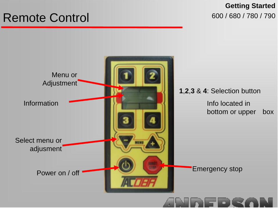
Remote Control 600 / 680 / 780 / 790
Menu or
Adjustment
Information
Select menu or
adjusment
Power on / offEmergency stop
1,2,3 & 4: Selection button
Info located in
bottom or upper box
Getting Started

Menu 1
1 2
MENU 1
Rev: 00 / 18 D o
Bal / (D): 0 0 0
Wrap
3 4
Number of bales wrapped per day
Number of revolutions performed / the
Number of revolutions desired
Access the following menu
Start Wrapping
Remote Control 600 / 680 / 780 / 790
Getting Started

Menu 2
1 2
MENU 2
Rev: 00 / 18 D o
Bal / (Y): 0 0 0
Wrap
3 4
Number of bales wrapped per year
Number of revolutions performed / the
Number of revolutions desired
Access the following menu
Start Wrapping
Remote Control 600 / 680 / 780 / 790
Getting Started
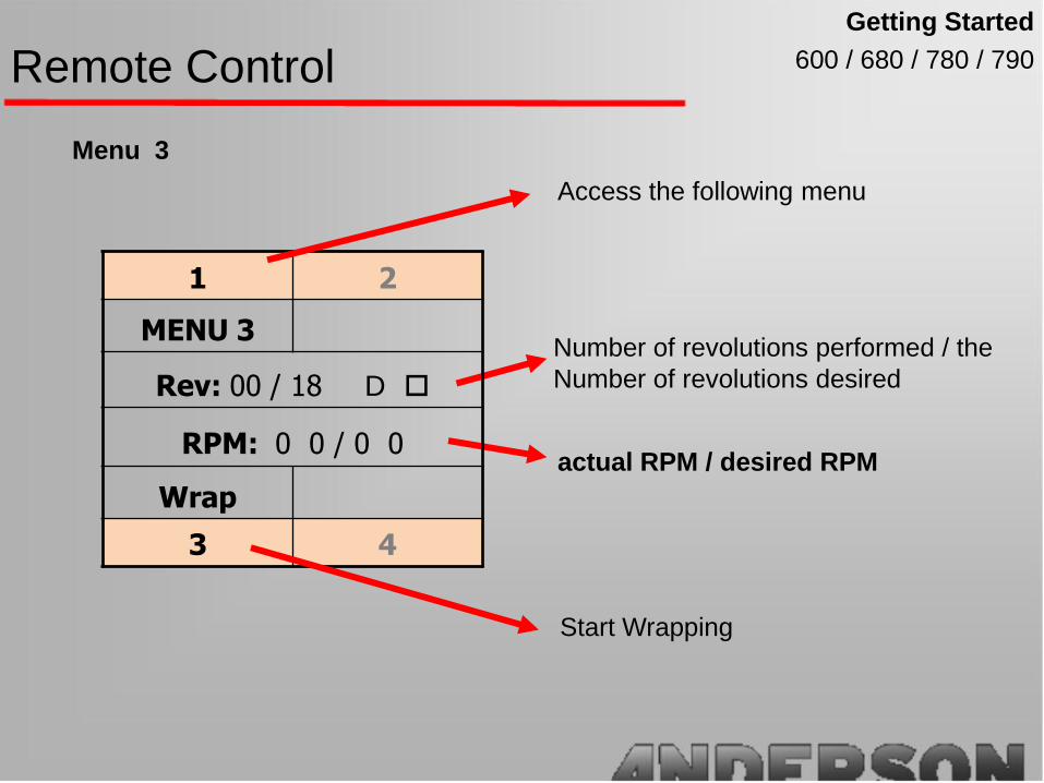
Menu 3
1 2
MENU 3
Rev: 00 / 18 D o
RPM: 0 0 / 0 0
Wrap
3 4
actual RPM / desired RPM
Number of revolutions performed / the
Number of revolutions desired
Access the following menu
Start Wrapping
Remote Control 600 / 680 / 780 / 790
Getting Started

Menu 4
Wrapper model (680, 780 or 780 + ¼)
Align menu
Access the following menu
Align the table
1 2
MENU 4 Cancel
Align D o
Wrapper
Align.
3 4
Cancel wrapping
Remote Control 600 / 680 / 780 / 790
Getting Started
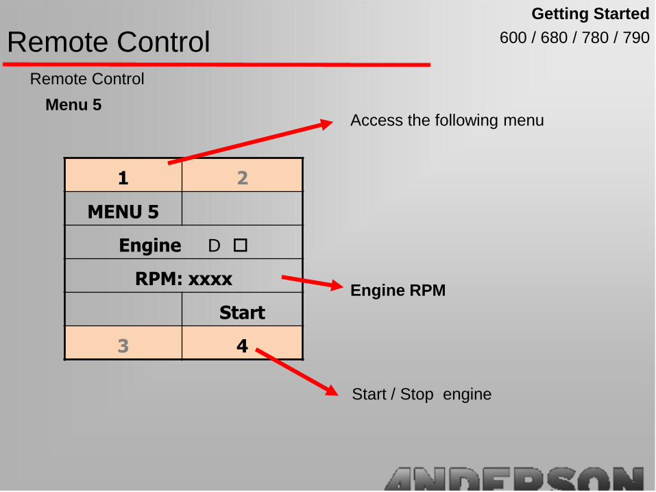
Menu 5
Engine RPM
Access the following menu
Start / Stop engine
1 2
MENU 5
Engine D o
RPM: xxxx
Start
3 4
Remote Control
Remote Control 600 / 680 / 780 / 790
Getting Started

Ajustment
To access adjustment mode : press + & - at the
same time and release them.
Adjustment 1: Numbers of turn to wrap a bale:
3 or 4: to change the number of turn
Recommended (16-25)
Adjustment 2: RPM of the rotary table
3 or 4: to change RPM
Recommended (20-24)
Press 1 : Access the following Adjustment
Remote Control 600 / 680 / 780 / 790
Getting Started

Ajustment
To access adjustment mode : press + & - at the same
time and release them.
Adjustment 3 : Bales wrapped per day,
2: Resset to 0
3 or 4: Change the number of bale
Adjustment 4: Wrapper model
3 or 4: Select wrapper model
680-780-780 1/4
Press 1 : Access the following Adjustment
Remote Control 600 / 680 / 780 / 790
Getting Started

Ajustment
To access adjustment mode : press + & - at the same
time and release them.
Adjustment 5 : Activate stretcher sensor
4: Select
Adjustment 6 : Language (french or english)
4: Select
Press 1 : Access the following Adjustment
Remote Control 600 / 680 / 780 / 790
Getting Started

Ajustment
To access adjustment mode : press + & - at the same
time and release them.
Adjustment 7: Contrast of the screen
3 or 4: Adjust contrast
Adjustment 8: Alignment of the table
3 or 4: Adjust Angle of Zero position
Then 2: Validate the alignment
Press 1 : Access the following Adjustment
Remote Control 600 / 680 / 780 / 790
Getting Started
Getting started
400/ 500/ 600 / 580/ 680 / 780 / 790
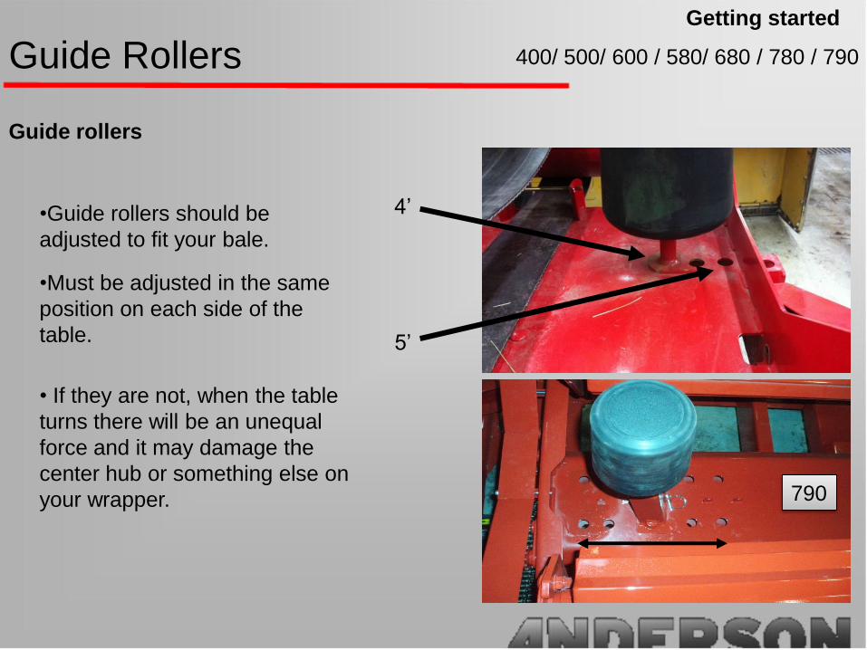
Guide rollers
•Guide rollers should be
adjusted to fit your bale.
•Must be adjusted in the same
position on each side of the
table.
• If they are not, when the table
turns there will be an unequal
force and it may damage the
center hub or something else on
your wrapper.
Guide Rollers
4’
5’
790

Getting started
400/ 500/ 600 / 580/ 680 / 780 / 790Plastic Film Roll
Install Plastic Film Roll
To install you just have to start by
pushing the support up with the
end of the plastic roll (as you see
in the photo) into the holders.
Pass the plastic film through the
stretcher as you see in the sticker
on the machine. Like the one in
the diagram on this page.
Make sure aluminum and rubber
rolls are clean and spin without
resistance.
Cleaning
Aluminum rolls: WD-40
Rubber roll Hot water and soap

Getting started
580/ 680
Drop off system allow the bale to
be dumped gently
The D-3 Option will able the
dumper to rotate placing the bale to
the left or right of the wrapper on its
end .
Regular dumping system
Drop off
No setting needed on D Drop off
system
D-3 upgrade kit

Drop off: 3D
Install the foot and remove the
pin to make the drop-off flip on
the desired side.
Adjust retaining bar to prevent
the bale from flipping over.
Adjust the length of the link to flip
the bale correctly
In field with
loading arm only
Drop offGetting started
580/ 680

Getting Started
580 / 680 / 790
•Will load bales directly onto the wrapper
•The table must be parallel to the loading arm
to load a bale.
•The arm must be dropped halfway so that the
table can wrap. A safety valve will prevent
collision between the two so you must have
the arm at the right position.
•Adjust the backstop to place the bale in the
right position to dump properly on the table.
•When transporting the unit. The arm must be
lifted and locked with the safety pin.
•The loading arm option is only installed at
Anderson facility.
Loading Arm
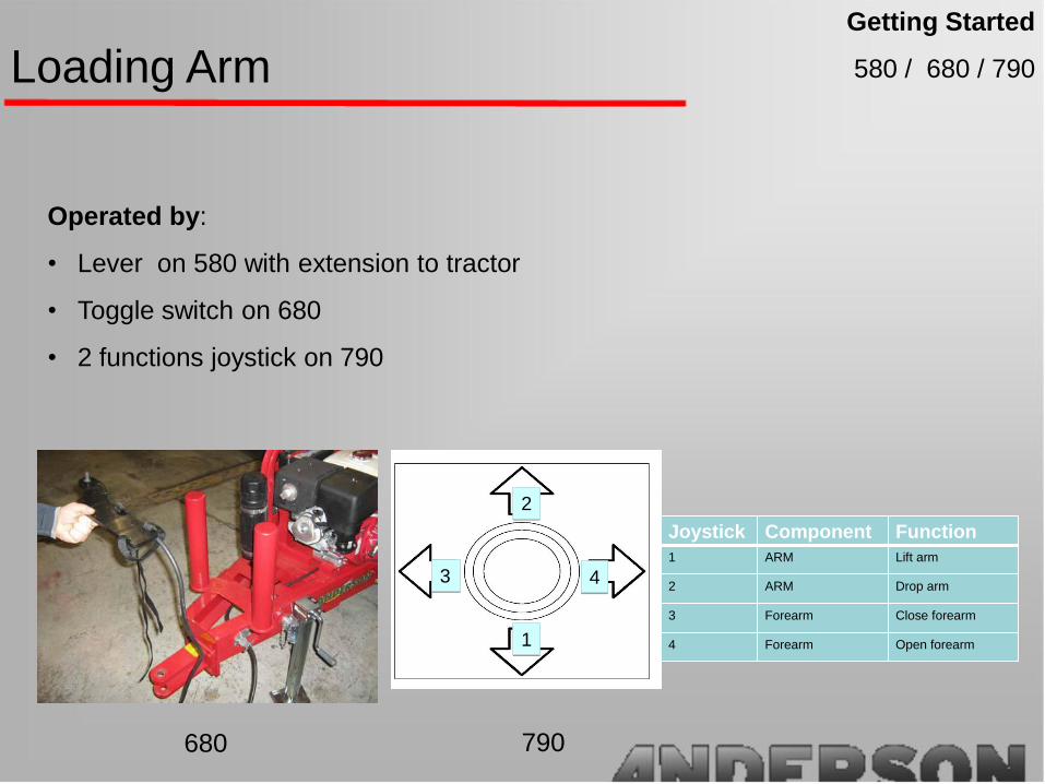
Getting Started
580 / 680 / 790Loading Arm
Operated by:
• Lever on 580 with extension to tractor
• Toggle switch on 680
• 2 functions joystick on 790
Joystick Component Function
1 ARM Lift arm
2 ARM Drop arm
3 Forearm Close forearm
4 Forearm Open forearm
22
33 44
11
Joystick Component Function
1 ARM Lift arm
2 ARM Drop arm
3 Forearm Close forearm
4 Forearm Open forearm
22
33 44
11
680 790

All modelsOperation
Recommended flow rate is 8 GPM at 2000 PSI
How many turns to wrap a bale?
A= Nb of turns to cover bale
nb Layer Formula
4 A x 2 + 2
6 A x 3 + 2
Plastic over lap is 50%
Safety for slipping or size variation
Operation
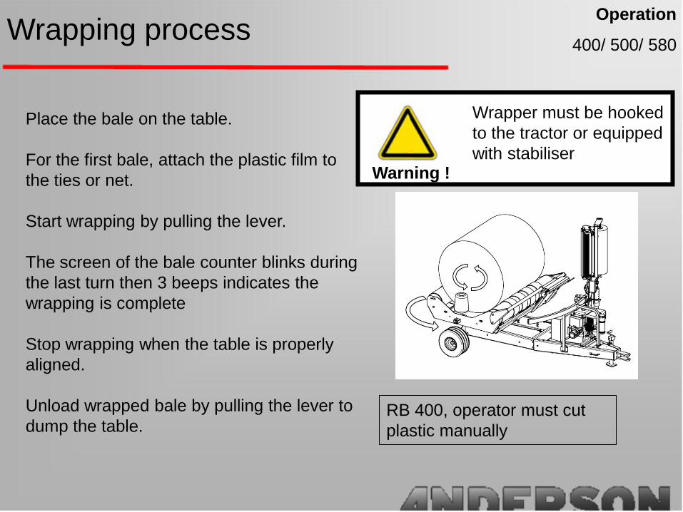
400/ 500/ 580Wrapping process
Place the bale on the table.
For the first bale, attach the plastic film to
the ties or net.
Start wrapping by pulling the lever.
The screen of the bale counter blinks during
the last turn then 3 beeps indicates the
wrapping is complete
Stop wrapping when the table is properly
aligned.
Unload wrapped bale by pulling the lever to
dump the table.RB 400, operator must cut
plastic manually
Wrapper must be hooked
to the tractor or equipped
with stabiliserWarning !

Wrapping Process
Place the bale on the table.
For the first bale, install the plastic film
into the cut and hold by using the lever.
Start wrapping by pressing the blue button
on computer or 3 on remote control.
Wrapping cycle will be completed
automatically
Operation
600 / 680 / 780 / 790
Wrapper must be hook to
the tractor or equipped
with stabiliserWarning !

Adjustments & Trouble Shooting
• Mechanical
- Cut and hold systems
- Table roller
- Table Safety pin
- Stretcher
- Drop off
- Engine
• Hydraulic
- Hydraulic schematic
- Close center
• Electronic
- Bale counter
- Computer
500/ 600 / 580
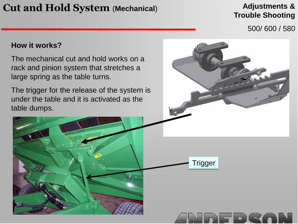
Cut and Hold System (Mechanical)
How it works?
The mechanical cut and hold works on a
rack and pinion system that stretches a
large spring as the table turns.
The trigger for the release of the system is
under the table and it is activated as the
table dumps.
Trigger
Adjustments &
Trouble Shooting
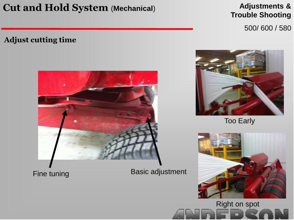
Adjust cutting time
Right on spot
Too Early
Fine tuning Basic adjustment
500/ 600 / 580
Cut and Hold System (Mechanical) Adjustments &
Trouble Shooting

Other adjustments
Cutting blade
•Needs to be sharp
500/ 600 / 580
Cut and Hold System (Mechanical) Adjustments &
Trouble Shooting
Note: Lubrication is very important for
the cut and hold to work properly
Spring
•You can adjust the spring of the cut and
hold (only if needed) as you see in the photo.
Spring Adjustment
500/ 600 / 580
Cut and Hold System (Mechanical) Adjustments &
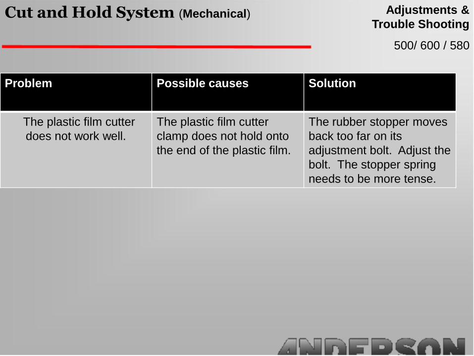
Trouble Shooting
Problem Possible causes Solution
The plastic film cutter
does not work well.
The plastic film cutter
clamp does not hold onto
the end of the plastic film.
The rubber stopper moves
back too far on its
adjustment bolt. Adjust the
bolt. The stopper spring
needs to be more tense.

680 / 780 / 790
Cut and Hold System (Hydraulic) Adjustments &
Trouble Shooting
The hydraulic cut and hold system is very simple to use. It can be used Automatic and
Manually. The pressure on the main valve must be between 2000 and 2100lbs. The
only adjustment possible is to raise the tension on the rubber bumper and fill the
accumulator (on models 780 and 790)
Maintenance
The Hydraulic Cut and Hold is very simple to maintain. You should keep it well lubricated
(by following the 4 lubrication points on the shield). And change the blade if it no longer
cuts well. Also make sure that there is no debris left in the cut and hold after operation.

780 (2011) new* / 790
Cut and Hold System (Hydraulic) Adjustments &
Trouble Shooting
Filling the accumulator
1. At the end of the ball-valve, there is a quick coupler. Install a hydraulic hose from the
ball valve to the tractor’s rear remote valve with a pressure gage in between the
quick coupler on the accumulator and the tractor.
2. Shut off the cut and hold from the main valve with the lever. (See photo #1 )
Quick coupler
Ball valve

780 (2011) new* / 790
Cut and Hold System (Hydraulic) Adjustments &
Trouble Shooting
Filling the accumulator
2. Unlock the handle of the ball valve. Unscrew the bolt and turn the locking washer to
be able to turn the handle (see below photos) Note: leave the ball valve closed with the
handle until step 4.
locked unlocked

780 (2011) new* / 790
Cut and Hold System (Hydraulic) Adjustments &
Trouble Shooting
Filling the accumulator
3. Unscrew slightly the bottom hose on the cylinder. (see photo #1)
Photo#1
4. Open the ball valve as in the previous
page.
5. In the tractor, Push the lever (oil control)
Gradually until the pressure gage raises to
2000psi (never exceed 2000psi). Then
release the lever. The oil will leak from the
fitting as in photo #1 with air bubbles and
the pressure will drop. When the pressure
has dropped below 500lbs you will repeat
this procedure 3 more times until there is
no more air bubbles in the system. You will
then screw back the hose tightly in the
photo #1.

780 (2011) new* / 790
Cut and Hold System (Hydraulic) Adjustments &
Trouble Shooting
Filling the accumulator
6. Next you will pull on the ball (as in photo below) and turn it 1/3 turn clockwise (It will
stay pulled out). This movement lets the plastic hold to open. You will go back to the
tractor and add Oil until you have 450PSI (This will fully open the cut and hold). At
this point you will close the ball valve on the accumulator.
Pull and turn 1/3 turn
780 (2011) new* / 790
Cut and Hold System (Hydraulic) Adjustments &
Trouble Shooting
Filling the accumulator
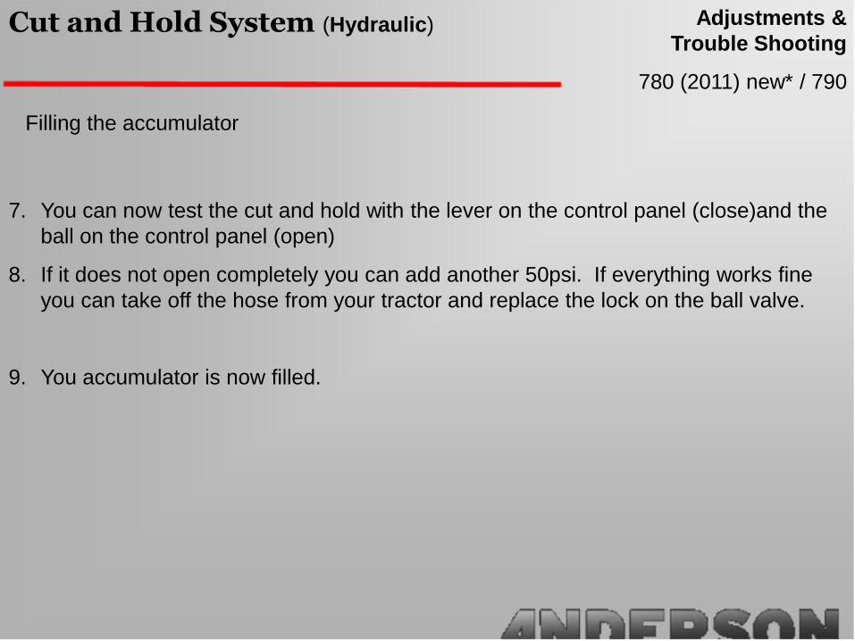
7. You can now test the cut and hold with the lever on the control panel (close)and the
ball on the control panel (open)
8. If it does not open completely you can add another 50psi. If everything works fine
you can take off the hose from your tractor and replace the lock on the ball valve.
9. You accumulator is now filled.

780 / 790
Cut and Hold System (Hydraulic) Adjustments &
Trouble Shooting
Problem Possible causes Solution
6. The plastic film cutter
does not work well.
The plastic film cutter clamp
does not hold onto the end
of the plastic film.
The rubber stopper moves
back too far on its
adjustment bolt. Adjust the
bolt. The stopper spring
needs to be more tense.
Verify the pressure on the
main valve
Be sure that the hydraulic
hoses are not damaged.

Factory adjust at 2nd hole
Needs adjustment if bale slips
on the belts
400 /500 /600 /580 /680
Table rollers Adjustments &
Trouble Shooting

37” between tandem shafts
Tandems have to be leveled
• Keep Shock and spring in
place no maintenance
780
Table rollers Adjustments &
Trouble Shooting
780 new /790
Table rollers Adjustments &
Trouble Shooting
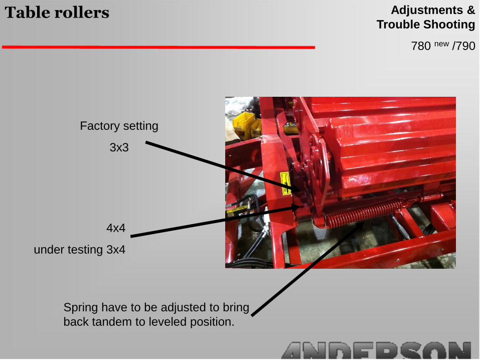
Factory setting
3x3
4x4
under testing 3x4
Spring have to be adjusted to bring
back tandem to leveled position.
580old /680 old /780 /790
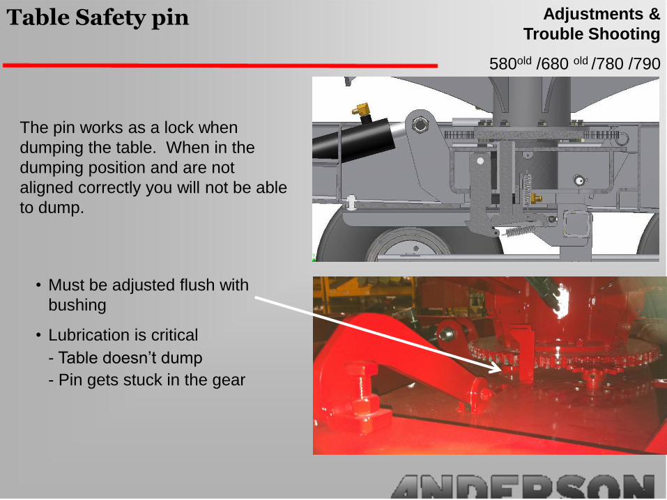
Table Safety pin Adjustments &
Trouble Shooting
• Must be adjusted flush with
bushing
• Lubrication is critical
- Table doesn’t dump
- Pin gets stuck in the gear
The pin works as a lock when
dumping the table. When in the
dumping position and are not
aligned correctly you will not be able
to dump.

• Pass a chain through the cross
member and the locking pin.
• With the lever handle (on the
main valve), raise up the table until
the pin comes out.
580old /680 old /780 /790
Table Safety pin Adjustments &
Trouble Shooting
Remove it when bended

400 /500 /600 /580 /680 /780 /790
Stretcher Adjustments &
Trouble Shooting
The Anderson stretcher works with gears that give
the correct tension on the plastic. These gears can
be replaced if needed and also a different set of
gears can be added if you are using the double
plastic roll application.
Brake on holder
There is a teflon break at the bottom of the
roll holder. This is used so that the plastic
does not unroll itself, as the speed of the
wrapper changes often during wrapping.
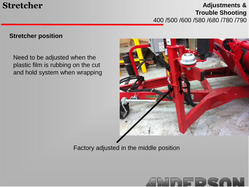
Need to be adjusted when the
plastic film is rubbing on the cut
and hold system when wrapping
Factory adjusted in the middle position
400 /500 /600 /580 /680 /780 /790
Stretcher Adjustments &
Trouble Shooting
Stretcher position
400 /500 /600 /580 /680 /780 /790
Stretcher Adjustments &
Trouble Shooting
Stretcher test
Draw 2 line 10 inch apart on the roll
After stretching, there must be 15,5 to 16,5
between them
Make sure aluminum and rubber rolls are
clean and spin without resistance.
Cleaning
Aluminum rolls: WD-40
Rubber roll Hot water and soap
10”
400 /500 /600 /580 /680 /780 /790
Stretcher Adjustments &
Trouble Shooting
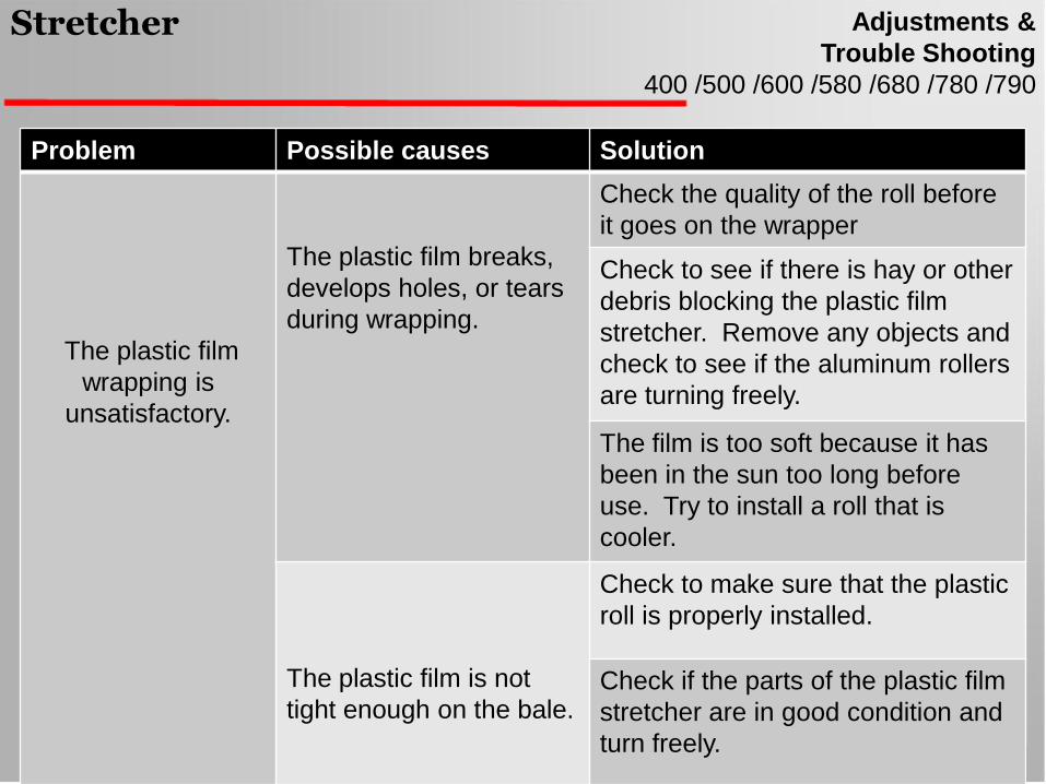
Problem Possible causes Solution
The plastic film
wrapping is
unsatisfactory.
The plastic film breaks,
develops holes, or tears
during wrapping.
Check the quality of the roll before
it goes on the wrapper
Check to see if there is hay or other
debris blocking the plastic film
stretcher. Remove any objects and
check to see if the aluminum rollers
are turning freely.
The film is too soft because it has
been in the sun too long before
use. Try to install a roll that is
cooler.
The plastic film is not
tight enough on the bale.
Check to make sure that the plastic
roll is properly installed.
Check if the parts of the plastic film
stretcher are in good condition and
turn freely.

1 2 3Sand the shaft first.
Kit to upgrade D drop off to 3D
580 /680
Drop offAdjustments &
Trouble Shooting
Installation
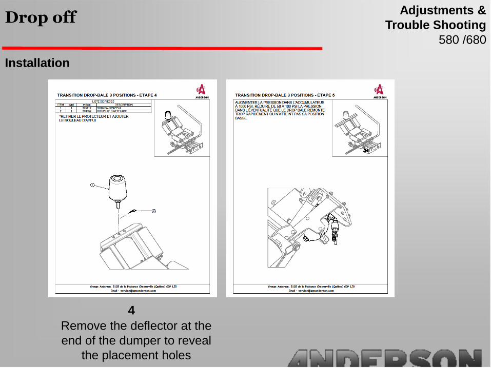
4
Remove the deflector at the
end of the dumper to reveal
the placement holes
580 /680
Drop offAdjustments &
Trouble Shooting
Installation
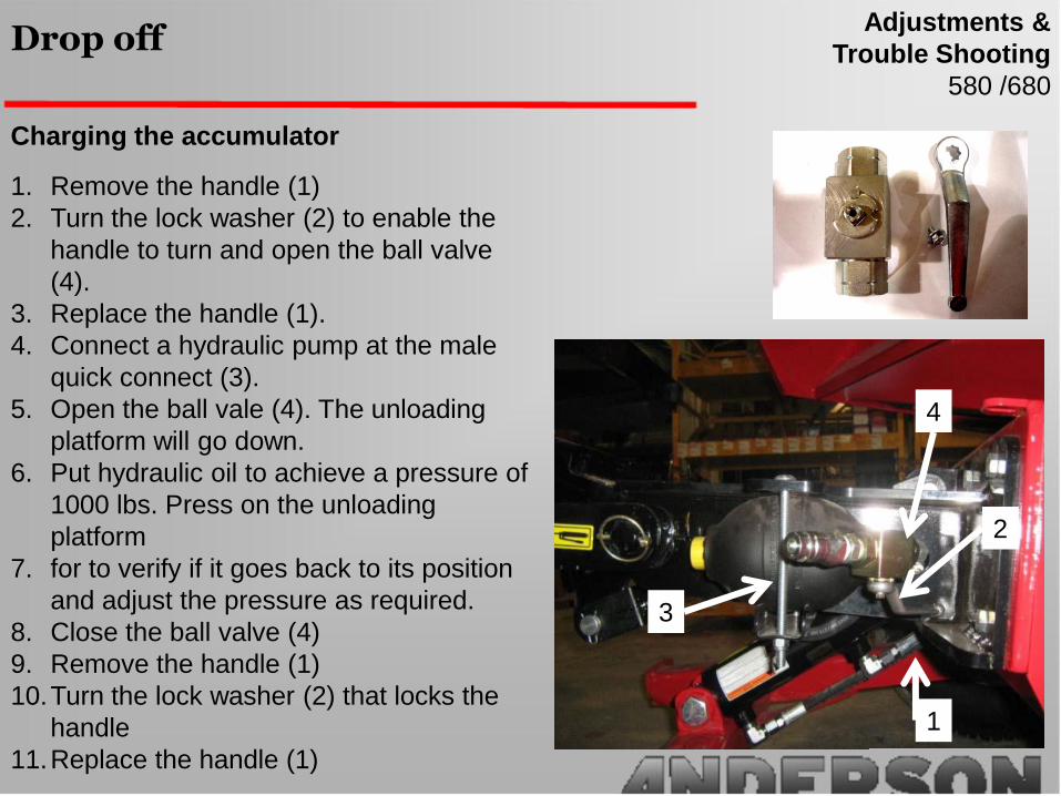
Charging the accumulator
1. Remove the handle (1)
2. Turn the lock washer (2) to enable the
handle to turn and open the ball valve
(4).
3. Replace the handle (1).
4. Connect a hydraulic pump at the male
quick connect (3).
5. Open the ball vale (4). The unloading
platform will go down.
6. Put hydraulic oil to achieve a pressure of
1000 lbs. Press on the unloading
platform
7. for to verify if it goes back to its position
and adjust the pressure as required.
8. Close the ball valve (4)
9. Remove the handle (1)
10.Turn the lock washer (2) that locks the
handle
11.Replace the handle (1)
580 /680
Drop offAdjustments &
Trouble Shooting
3
1
2
4

580 /680
Drop offAdjustments &
Trouble Shooting
Problem Possible causes Solution
The bale keeps
rolling when
dumped
The ski is not adjusted
properly and there is too
much play
The adjustment on the ski must be
set so that there is just enough time
for the bale to flip
Check to see if there is hay or other
debris blocking the plastic film
stretcher. Remove any objects and
check to see if the aluminum rollers
are turning freely.
The film is too soft because it has
been in the sun too long before
use. Try to install a roll that is
cooler.
The plastic film is not
tight enough on the bale.
Check to make sure that the plastic
roll is properly installed.
Check if the parts of the plastic film
stretcher are in good condition and
turn freely.

400 /500 /600 /580 /680 /780 /790
EngineAdjustments &
Trouble Shooting
Unload top RPM: 3900
Recommended RPM: no less 3600 RPM
Gas line must be turned off during transport
When starting the motor for the first time of the
day / year the choke must be used.
400 /500 /600 /580 /680 /780 /790
EngineAdjustments &
Trouble Shooting
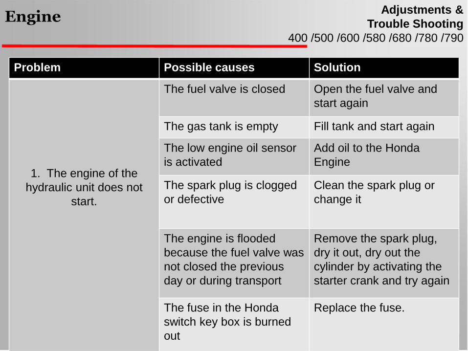
Problem Possible causes Solution
1. The engine of the
hydraulic unit does not
start.
The fuel valve is closed Open the fuel valve and
start again
The gas tank is empty Fill tank and start again
The low engine oil sensor
is activated
Add oil to the Honda
Engine
The spark plug is clogged
or defective
Clean the spark plug or
change it
The engine is flooded
because the fuel valve was
not closed the previous
day or during transport
Remove the spark plug,
dry it out, dry out the
cylinder by activating the
starter crank and try again
The fuse in the Honda
switch key box is burned
out
Replace the fuse.

400 /500 /580
Hydraulic SchematicAdjustments &
Trouble Shooting
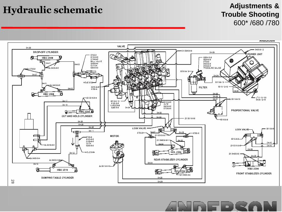
600* /680 /780
Hydraulic schematicAdjustments &
Trouble Shooting

600* /680 /780
Hydraulic schematicAdjustments &
Trouble Shooting
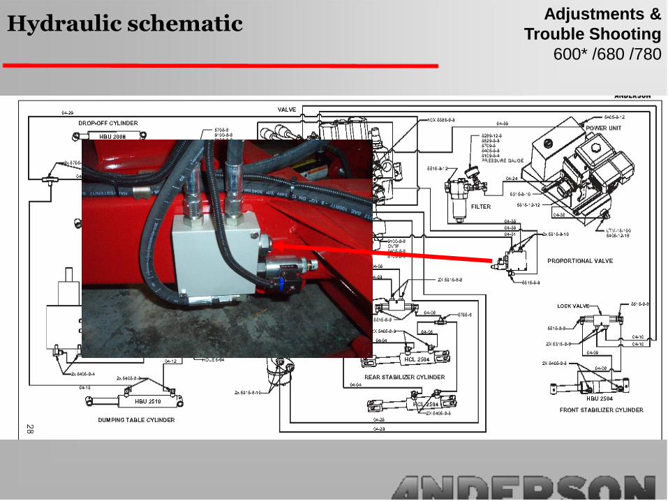
600* /680 /780
Hydraulic schematicAdjustments &
Trouble Shooting

600* /680 /780
Hydraulic schematicAdjustments &
Trouble Shooting

790
Hydraulic schematicAdjustments &
Trouble Shooting

1- Unscrew the hose and the hydraulic fitting
from the out port of the valve (A).
2- Install plug (¼ npt) in the hole.
3- Put back the hose and the hydraulic fitting
unscrewed on step (1).
4- Remove the plastic cap of the main relief
valve.
5- Screw clockwise 1 ½ turn and put back the
plastic cap (B). Pressure should be 2500 psi.
A
B
400 /500 /580
Close CenterAdjustments &
Trouble Shooting
(4) Install plug here (provided)
(1) Unscrew those 2 hoses
(2) Remove those fittings from the valve
(3) Remove this hose and all the fittings
from the “T” up to the main
valve
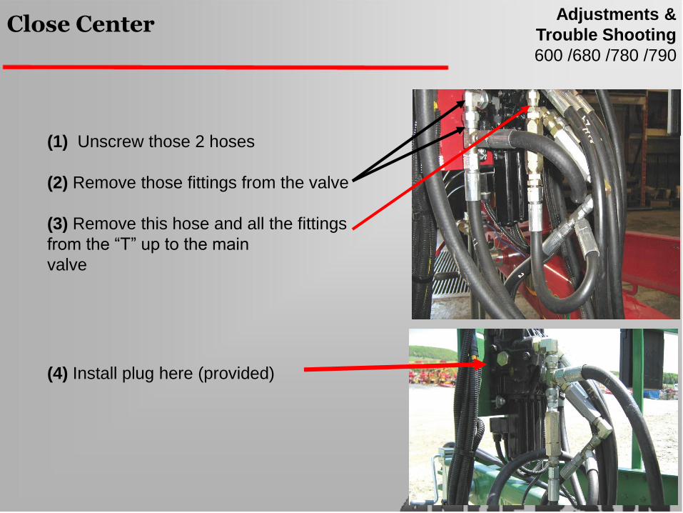
600 /680 /780 /790
Close CenterAdjustments &
Trouble Shooting

(5) Remove completely the hose and
replace by a plug (provided)
(6) Install plug ¼’’ NPT in this hole
600 /680 /780 /790
Close CenterAdjustments &
Trouble Shooting

(7) Install like the picture the hose
provided by ANDERSON and plug
the last hose
(8) Remove the plastic cap and
Screw the main relief allen screw
clockwise 1 ½ turn. (2500 psi)
600 /680 /780 /790
Close CenterAdjustments &
Trouble Shooting

400 /500 /580
Bale counter IG-C3Adjustments &
Trouble Shooting
2. Verify the sensor that is situated at the end of
the wire and the magnet that is placed on the
large sprocket. If one of the two are defective
you will have to change them. The distance
required for proper functioning of the sensor is
18’’ between the sensor and the magnet. (See
the next page for location of this sensor)
3. It is possible that the counter is not working
properly as well. To test the conter you will take a
screw driver and touch the two pins of the
connection (as in the photo on this page. Each
time that they touch the number of turns should
increase. It is possible that the battery could
cause this problem. Always be sure to have 12V on your battery at all times.
If the rotations no longer show on the counter
1. Check the electrical wire between the counter and the sensor.

400 /500 /580
Bale Counter IG-C3Adjustments &
Trouble Shooting

1- Open the computer’ door
2- Turn ON ( Emergency stop button)
3- Turn ON the remote control
4- Press once the Little black button inside computer
(1 time = remote association)
5- On remote control press 2 (ASS)
Wait 4 seconds
6-Press 4 (ASS. COMPLETE)
Computer and remote control are now associated
Repeat if needed
If it doesn’t work, reset the computer
Association of Remote Control
600 /680 /780 /790
Computer TAC-08CAdjustments &
Trouble Shooting

Error code
[Out of range]
Search during start-up failed.
Receiver is turned off.
Receiver is too far away.
Remote control is not associated.
[TAC-08 / RF Error]
Technical problem with the remote control.
Must be returned to Anderson for replacement.
[Version / incompatible]
Different programming between receiver and
remote control. Program must be updated.
[Hydraulic problem, lack of fuel, or loading arm
too high! / Hydraul. Fuel]
Three causes of the malfunction of the table, the
wrapper, or the engine. Check.
600 /680 /780 /790
Computer TAC-08CAdjustments &
Trouble Shooting

Error code
[Problem with plastic film, ripped or empty! /
plastic]
Plastic roll empty.
Plastic film broken
Sensor need adjustment (1/8” distance)
[Rotation sensor error / Rotation]
Malfunction of the encoder. Check, wiring and
encoder damage
[Zero setting sensor error / Zero setting]
Malfunction of the Zero sensor.
Sensor need adjustment (1/8” distance)
.
[Unloading sensor error / Unloading]
Malfunction of the sensor.
Sensor need adjustment (1/8” distance)
600 /680 /780 /790
Computer TAC-08CAdjustments &
Trouble Shooting

Reset Computer TAC-08C
1. Turn OFF computer (Emergency stop button)
2. Open computer’ door
3. Press and hold the blue (or green) button on the door.
4. Turn ON ( Emergency stop button)
5. Press the black button 2 time to enable the test mode.
6. Release the blue (or green) button
7. Turn off computer (Emergency stop button)
8. Wait 5 seconds before any other operation.
9. Process 3 times to alignment (with shut down between
them)
Computer memorise oil flow data for smooth start and
stop.
10.Process to a wrapping test. Make sure to turn the
stretcher roll or deactivated stretcher sensor
600 /680 /780 /790
Computer TAC-08CAdjustments &
Trouble Shooting

600 /680 /780 /790
Computer TAC-08CAdjustments &
Trouble Shooting
Wiring Diagram

600 /680 /780 /790
Computer TAC-08CAdjustments &
Trouble Shooting
Sensor diagnostic
Plastic film
Encoder
Dumping
Zero position
Engine
Sensor light

600 /680 /780 /790
Computer TAC-08CAdjustments &
Trouble Shooting
Sensor Adjustment
Distance must be 1/8” between sensor and
component
Before adjust sensor on dumping table:
Make sure the tolerance is no more than
1/16” between table and frame
Old version: Zero position
Sensor 3/8 diameter
Read bolt head, instead of
a hole

600 /680 /780 /790
Computer TAC-08CAdjustments &
Trouble Shooting
Computer version
Green button: 1.1.16
1.1.17
1.1.16E
1.1.17E
E = encoder
- Old valve
- 5 wires coming out of computer
Blue button: 1.2.3 - New valve, 3 wires
1.2.8 Latest version
1.1.17(E) and 1.2.8 780 +1/4, table over turn when positioning
1.2.8 Additional connection for loading arm and cut and hold

600 /680 /780 /790
Computer TAC-O8CAdjustments &
Trouble Shooting
Problem Possible causes Solution
2. The TAC-08C receiver
does not work
Defective power supply Check the battery contacts
and the electric
connectors. Clean them if
needed.
A minimum of 12 V. is
necessary.
Check the performance of
the battery and the
alternator. Correct if
necessary.
The fuse (s) in the receiver
case are burnt out
Replace the defective
fuses in the computer
case.
The power cable fuse is
burnt out
Replace the defective
fuse.

600 /680 /780 /790
Computer TAC-O8CAdjustments &
Trouble Shooting
Problem Possible causes Solution
3. The TAC-08A remote
control does not work (or is
not associated)
The transmitter battery is
dead (remote)
Install the charger and
charge the remote or work
with the DC wire
connected
The remote control is not
associated
See the remote control
association section.
Problem Possible causes Solution
4. Table alignment cannot
be performed
The battery on the unit is
too weak
Make sure that you have
12V by recharging or
changing the battery.
Defective electrical
connections
Check the electrical
connections (connectors
on the hydraulic valves).
See alignment procedure.

600 /680 /780 /790
Computer TAC-O8CAdjustments &
Trouble Shooting
When Light flash after aligment: There is a problem with
a connection.
The most common problem with the computer is when
the 12 v min is not met.

Problem Possible causes Solution
5. The turntable does not
turn or turns slowly.
The hydraulic oil level is
too low. Loss or lack of oil.
Check for oil leaks and
breaks. Retighten or
repair as necessary. Add
hydraulic oil to the tank.
Check if you have 12V. On
the wrapper battery
Recharge if needed.
The Honda engine does
not turn at the proper
speed
The engine must be
adjusted to 3600
revolutions / min.
Trouble shooting (general)All individual wrappers
Problem Possible causes Solution
6. The plastic film cutter
does not work well.
The plastic film cutter
clamp does not hold onto
the end of the plastic film.
The rubber stopper moves
back too far on its
adjustment bolt. Adjust the
bolt. The stopper spring
needs to be more tense.

Every 200 bales:
•Pivot of plastic film roll support (1)
•Pivot of unloading platform (4)
•Central axle of turntable (1 on top)
•Pivots and barrier of tilting table (3)
•Plastic film cutter (3 underneath and 1 on the side)
•Axles of the unloading table cylinder
Every 500 bales
•front and rear stabilizers (2 each)
•Axles of the front stabilizer cylinders (2 each)
•Tandem axles (1 each)
Every 1000 bales
•Bearing of the two feed rollers of the belts (1 on
each end, total of 4)
Lubrication schedule
It si very important to remove
all debris from the guards
before lubrication and after
wrapping each day.
Maintenance (general)
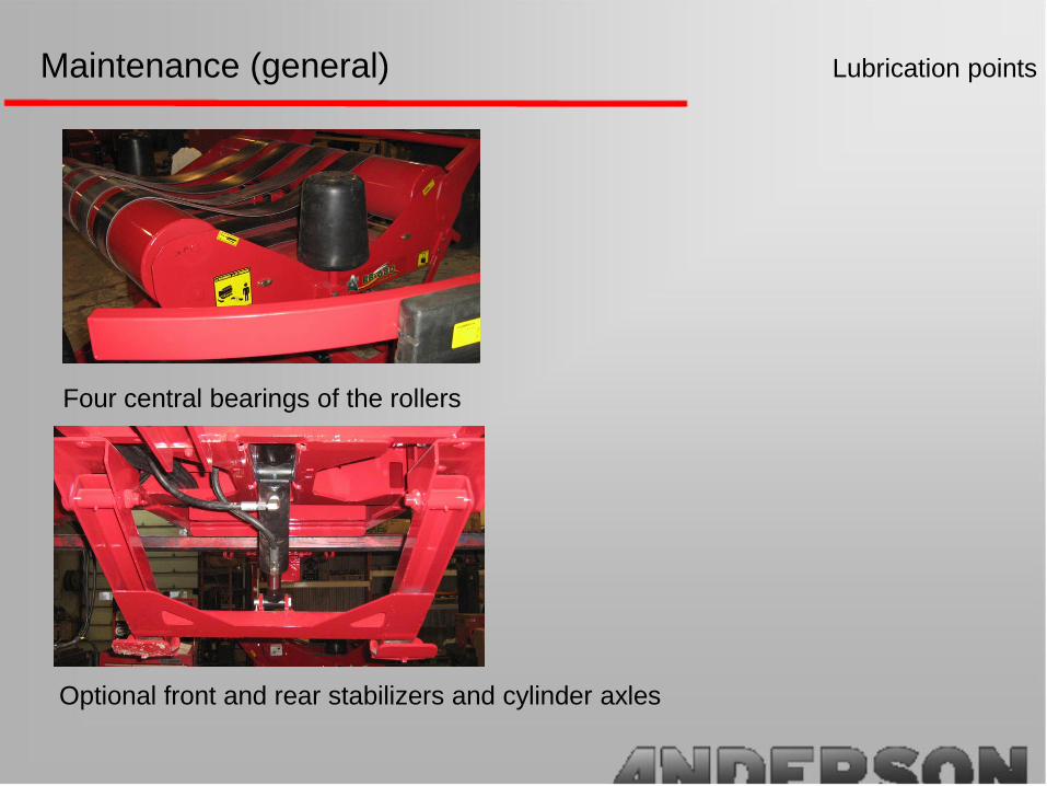
Lubrication points
Four central bearings of the rollers
Optional front and rear stabilizers and cylinder axles
Maintenance (general)

Lubrication points
Plastic film cutter
Pivot of dumping table
Maintenance (general)

Lubrication points
Central axle of turntable
Pivot of loading arm
Maintenance (general)

Lubrication points
Pivot of unloading platform
Maintenance (general)

If you have received the machine that is not fully assembled you will have to assemble the unit before you go over the machine as you may not notice missing parts.
Check for any damage. Loose bolts missing bolts and paint.
Connect the battery (Anderson disconnects the battery for transport and for storage as well)
Grease and lubricate all of the points that have been marked by the yellow stickers (You can find a summary of the locations of these points in the user manual that accompanies the machine.
Check the Oil level of the Honda engine. Add oil if necessary (10W30)
Check fluid level of the hydraulic tank. There is a gauge on the top of the cap. Add fluid if necessary (TDH)
Start the Honda motor and warm up the hydraulic fluid for 3 to 5 minutes.
Check list (before delivery to end user)
Test the machine with the manual hydraulic valves located on the control panel. Be sure that all functions are working.
Test the cut and hold system, the dumping table and the loading arm if equipped
Do a system alignment with the remote control.
After a 15 minute short test you should be able to cover all that is on the checklist.
You should always check for fluid leaks after you have run the Honda Engine.
_______________________ checklist operator signature
_____________________________ Date
Check list (before delivery to end user)