siemens westinghouse power corporation, missile
TRANSCRIPT

SIEMENSWestinghouse
August 8, 2003
Mr. Brian BenneyProject Manager, Section 2Project Directorate IVDivision of Licensing Project ManagementDocument Processing Center, Mail Stop 07E1United States Nuclear Regulatory CommissionWashington, DC 20555-0001
Subject: Siemens Westinghouse Power Corporation, aMissile Probability Analysis of BB81/2811 3.9m2 ", TAC No. MB7964.
Dear Brian:
Attached please find RAI questions submitted by the NRC for the BB81/281 13.9m2 missile analysisand responses provided by Siemens Westinghouse (Attachment 1). One of the questions wasanswered by providing a technical paper recently prepared on the benefit of compressive residualstresses for nuclear rotor discs. This paper is included as Attachment 2.
The original Topical Report we submitted, CT-27332 Revision 0, has been revised to be in fullcompliance with the NRC recommendations in the Safety Evaluation (SE) report. This revised reportCT-27332 Revision 2 is enclosed as Attachment 3.
Re rds,
Peter BirdField Service Engineering S326Siemens Westinghouse Power CorporationPhone: (407) 736-4686
Enclosures:
1) RAI for Topical Report, aMissile Probability Analysis of BB81/281 13.9m2", SiemensWestinghouse Power Corporation, Response Submitted August 8, 2003.
2) Walter David, Dr. Andreas Feldmueller, Dr. Heinrich Oeynhausen, 'Shrunk on Disk Technology inLarge Nuclear Power Plants - the Benchmark against Stress Corrosion Cracking", to be
-- f 10
NRC 13.9m2 Letter3.doc
SIEMENSWestinghouse
presented at the Parsons Conference, September 16-18, 2003, Dublin, Ireland, Siemens PowerGeneration.
3) "Missile Probability Analysis for BB81/281 13.9m2", by P. Bird and Dr. A. Bagaviev, August 8,2003, CT-27332 Revision 2, Siemens AG - Power Generation.
cc: James McCracken S326Jim Auman S326Andreas Feldmueller S327Dr. Albert Bagaviev S321
NRC 13.9m2 Lefter3.doc

-RAI FORTOPICAL REPORT
"MISSILE PROBABILITY ANALYSIS OF BB81/281 13.9M 2"SIEMENS WESTINGHOUSE POWER CORPORATION
Response Submitted August 8, 2003
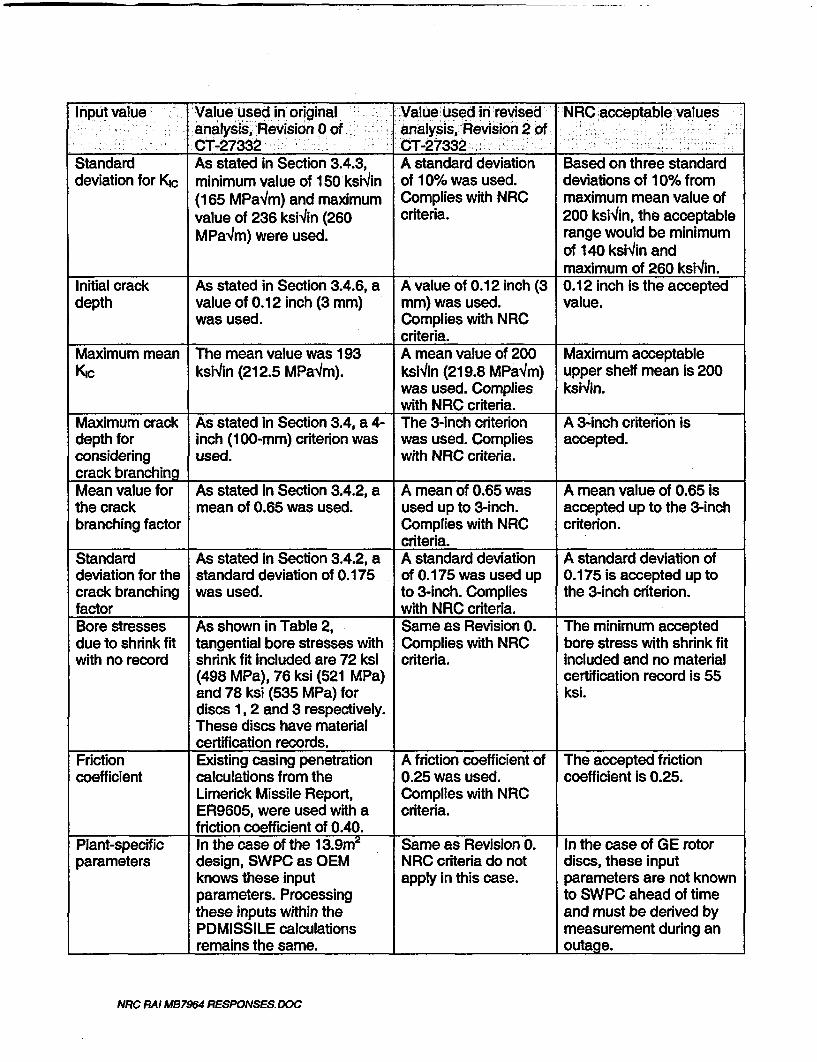
(1) The staff's position regarding acceptable values for some key deterministic andprobabilistic parameters used in a typical turbine missile analysis considering diskburst and casing penetration was stated in a safety evaluation (SE) of Siemensturbine missile methodology dated April 2, 2003. A list of these parameters isprovided below:
Standard deviation for KjcInitial crack depthMaximum mean KcMaximum crack depth for considering crack branchingMean value for the crack branching factorStandard deviation for the crack branching factorBore stresses due to shrink fit with no recordFriction coefficientPlant-specific parameters
Please identify the parameters in your current analysis that assumed differentvalues or probabilistic distributions than their corresponding ones accepted by thestaff in the April 2, 2003 SE and assess the impact of the differences on yourresults and conclusion.
ResDonse:Unfortunately, the 13.9m2 missile analysis documented in CT-27332 Revision 0was performed in the Fall of 2002, the original Missile Report issued in February2003 and the NRC Safety Evaluation (SE) In April 2003. Because of these timedifferences, there are differences In the input parameters used and thoserecommended by the NRC staff in the SE. As summarized in the attachedtabulation, the two input parameters that were not consistent with the NRC staffrecommendations are maximum crack depth for considering crack branching andfriction coefficient in the casing penetration calculations.
With regard to maximum crack depth for considering crack branching, the missileanalysis has been revised to use the 3-inch criterion. Reference Revision 2 of CT-27332 as attached in a separate document. This revised report complies with all ofthe NRC recommendations for input parameters.
The casing penetration analysis used in CT-27332 Revision 0 Is the same existinganalysis used for the Limerick design, which applies and is discussed in ER9605(one of the submittals to the NRC). This analysis used a friction coefficient of 0.40.Use of a 0.25 friction factor per latest NRC recommendation results in increasedcasing penetration probabilities for each disc. Revision 2 of CT-27332 includes theeffect of the 0.25 friction coefficient in the missile energy calculations.
NRC RAI MB7964 RESPONSES.DOC

A sensitivity study was performed for the purpose of evaluating the effect of frictioncoefficient on casing penetration probability. Results are summarized on thefollowing figure. Calculations were made for each of the three discs at frictioncoefficients of 0.40 (same as Limerick), 0.10 and zero. The zero case was madeassuming no friction between disc fragments, blades and casings during energydissipation within the LP turbine after burst.
13.SM2 MISSILEANALYSISEAT, OF FRcTION COEMICtENr ON CASING
PEETRATION PROBABILITY
1.00E-03 -
0
o1.OOE-06
FRICTIONC OFICINT
0 0.1 2c 1 0.Disc2 5Dis3
NRC RAI MB7964 RESPONSES.DOC
Input value Value used in original- Value used in revised NRC acceptable valuesanalysis,fl Revision 0 of analysis,-Revision2 of
__ __ _ __ _ CT-27332 CT-27332 i - _-E__X-;t__:___-__
Standard As stated in Section 3.4.3, A standard deviation Based on three standarddeviation for Kc minimum value of 150 ksiin of 10% was used. deviations of 10% from
(165 MPaqm) and maximum Complies with NRC maximum mean value ofvalue of 236 ksWin (260 criteria. 200 ksiin, the acceptableMPa'/m) were used. range would be minimum
of 140 ksiWin andmaximum of 260 ksivin.
Initial crack As stated in Section 3.4.6, a A value of 0.12 inch (3 0.12 inch is the accepteddepth value of 0.12 inch (3 mm) mm) was used. value.
was used. Complies with NRCcriteria.
Maximum mean The mean value was 193 A mean value of 200 Maximum acceptableKc ksiIin (212.5 MPa4m). ksi4in (219.8 MPa'm) upper shelf mean is 200
was used. Complies ksi4in.with NRC criteria.
Maximum crack As stated in Section 3.4, a 4- The 3-inch criterion A 3-inch criterion isdepth for inch (100-mm) criterion was was used. Complies accepted.considering used. with NRC criteria.crack branchingMean value for As stated in Section 3.4.2, a A mean of 0.65 was A mean value of 0.65 isthe crack mean of 0.65 was used. used up to 3-inch. accepted up to the 3-inchbranching factor Complies with NRC criterion.
criteria.Standard As stated in Section 3.4.2, a A standard deviation A standard deviation ofdeviation for the standard deviation of 0.175 of 0.175 was used up 0.175 is accepted up tocrack branching was used. to 3-inch. Complies the 3-inch criterion.factor with NRC criteria.Bore stresses As shown in Table 2, Same as Revision 0. The minimum accepteddue to shrink fit tangential bore stresses with Complies with NRC bore stress with shrink fitwith no record shrink fit included are 72 ksi criteria. included and no material
(498 MPa), 76 ksi (521 MPa) certification record is 55and 78 ksi (535 MPa) for ksi.discs 1,2 and 3 respectively.These discs have materialcertification records.
Friction Existing casing penetration A friction coefficient of The accepted frictioncoefficient calculations from the 0.25 was used. coefficient is 0.25.
Limerick Missile Report, Complies with NRCER9605, were used with a criteria.friction coefficient of 0.40.
Plant-specific In the case of the 13.9m Same as Revision 0. In the case of GE rotorparameters design, SWPC as OEM NRC criteria do not discs, these input
knows these input apply in this case. parameters are not knownparameters. Processing to SWPC ahead of timethese inputs within the and must be derived byPDMISSILE calculations measurement during anremains the same. outage.
NRC RAI MB7964 RESPONSES. DOC

(2) Section 3.3 and Figure 8 present the residual stress distribution due tomanufacturing without adequate explanation. Please provide basis for this residualstress distribution, e.g., analytical (FEM) results with experimental verification.Also, the effective stresses should include tensile stresses due to shrink-fit. UpdateFigure 8 to reflect this modification, and assess its impact on your results andconclusion.
Response:
Attachment 1: Siemens technical paper "Shrunk on Disk Technology in LargeNuclear Power Plants - the Benchmark against Stress Corrosion Cracking", to bepresented at the upcoming Parson's Conference of September 16-18, 2003 inDublin.
This paper provides the most current basis for residual stress distribution alongwith analytical results and experimental verification. Figure 14 in the technicalpaper superimposes the centrifugal forces, tensile stresses due to shrink fit andresidual stresses, as requested. The result is essentially the same conclusion aspresented in Figure 8 of CT-27332 for BB81/281 13.9m LP turbines. The onlydifference is that Figure 8 is based on results at 120% of rated speed, whereasFigure 14 in the technical paper is based on results at rated speed. Therefore, webelieve that Figure 8 applies and does not need to be updated.
(3) Section 3.4.7.1 mentions that "...using standard statistical evaluation procedures,the crack initiation probabilities at 90% confidence level for the #1 disks are asshown in Table 2." Provide information regarding this standard statisticalevaluation procedure. The information should include the number of indications,the number of reactor years or the number of disks, and the assumed probabilitydistribution (e.g., log-normal or binomial).
Response:
For large values of N (disk number) or small values of n (disks with flaws), theestimated probability of crack initiation p is small (p < 0.1), and the binomialdistribution can be approximated by a Poisson distribution.
The bounds for the Poisson parameter X at a confidence level of 90% are [0.1;3.89] for 1 indication (among 82 #1 disks) and [0.53; 5.3] for 2 indications (among324 back end disks), independent on the sample size N.
The upper value of the Poisson parameter at 90% Confidence Level for n = 1, A =3.89 and with N = 82:
p = (A / N )=(3.89/82 )= 0.047
The upper value of the Poisson parameter at 90% Confidence Level for n = 2, A =5.3 and with N = 324:
p=(A/N)=(5.3/324)=0.0164
NRC RAI MB7964 RESPONSES.DOC

(4) The energy equation in section 4.1.1 is not correct. Please revise it.
ResDonse:
Revision 2 of CT-27332 corrects this error.
(5) Section 4.1.3 calculation results for "ductile fracture" of disks. Confirm that theductile fracture methodology is the same as ductile burst methodology that theNRC reviewed as related to the April 2, 2003 SE. If ductile fracture means Jintegral - fracture resistance (J-R) approach, then you need to provide details.Ukewise, confirm that the probability of overspeed was calculated in accordancewith ER-504, and provide additional Information if it is not.
Response:
This is a wording issue only. The approach Is the same as the ductile burstmethodology presented and approved in the April 2, 2003 SE. We confirm that theprobability of overspeed was calculated in accordance with ER-504.
In summary, we believe that the 13.9m2 missile analysis as documented in CT-27332Revision 2 complies with all of the NRC criteria identified in the Safety Evaluation (SE)dated April 2, 2003.
NRC MI M87964 RESPOSES.DOC
Shrunk on Disk Technology In Large Nuclear Power Plants -the Benchmark against Stress Corrosion Cracking
Walter David, Dr. Andreas FeldmLller and Dr. Heinrich OeynhausenSiemens Power Generation
Introduction
The modemisation of steam turbines to improve plant efficiency plays an important role inreaching the targets set at Kyoto.
Especially blades, developed in the last years, combined with new sealing technologies andturbine casings with optimised flow paths' are key factors for ecological, as well aseconomical, Improvements of a power plant
Regarding the modemisation of power plants, along with efficiency Is the issue of reliabilityof the equipment a driving force.In the last decades, many turbines, especially in nuclear plants, were affected by stresscorrosion cracking (SCC), mainly in the large IP rotors2.
Repair work Is often time consuming and neither supports the economics nor solves generaldesign deficiencies. Therefore newly designed equipment, applying latest technology toImprove reliability, as well as efficiency, is often a more advantageous option.
As large half speed (150011800RPM) LP turbines were first developed in the late 60s,qualified monoblock rotors were not available in the required sizes. Therefore most of theturbine suppliers started to develop LP turbines with shrunk on disk designs.
Although the basic principle was the same, the design details of the suppliers were extremelydifferent and varied widely in their ability to avoid SCC from excellent to poor, i.e., stronglyaffected by SCC. Figure 1 shows typical problems with stress corrosion cracking found onshrunk on disk rotors in the past 2, AMl major manufacturers worldwide, except one, had toimprove their design due to a large numbers of reported failures which led to the shrunk ondisk generally receding a poor design reputation. Because of this, most suppliers convertedto using monoblock rotors as their design principle, based on Improvements In large forgings,or welded rotors.
This paper will show that in contrast to this, a shrunk on disk rotor is not just an alternativedesign, but rather should be regarded as the benchmark for all other nuclear LP rotordesigns.
With a closer examination of the background of the SCC phenomenon, It will be cear to allthat the design details are the distinguishing factors and not the design principle itself. Thisnotion Is supported by the fact that the turbines built with the technology described In thispaper did not experience an SCC problem. This technology was chosen to replace LPturbine rotors built by various original equipment manufacturers, including all varieties ofdesign principles, such as:
-Shrunk on disk 3-Monoblock 4-Welded disk
The reason for the replacement of these rotors was the gain in efficiency and power, butoften a reliability problem (e.g., SCC In the blade attachments) was an additional reason forthe modemisation.
Parsons 2003, David, Feidmaller, Ocynhausen I _ 16.48. Septmber 2003, Dublin

Examples of these different designs which have been replaced by the advanced shrunk ondisk rotor design developed by Siemens PG can be seen in Figure 2.
Design history of the Advanced Shrunk on Disk RotorsThe original Siemens KWU shrunk on disk designs for large nuclear LP turbines werebased on ten disks per rotor (see Figure 3). With the advanced shrunk on disk rotor designsthe number of disks per flow was reduced as this was found to be beneficial for efficiency, aswell as SCC prevention. As an example, the larger first disk, allows for an Increased numberof blade stages to reduce stage loading and increase blade efficiency. Moreover thecompressive stresses applied during heat treatment (see below) benefit from this designmodification.
On top of the reduced number of disks, It was found that in the last two disks per flow, anti-rotation keys were not required If a sufficient shrink fit was applied.
The following portion of this paper describes the SCC phenomenon and the preventativemeasures to avoid SCC attacks on the rotor components.
Stress Corrosion Cracking of Turbine Disks
In Figure 4, the factors Influencing the stress corrosion cracking behaviour (SCC) and theSiemens measures to avoid SCC are summarized. Although Siemens KWU low-pressureturbines were not affected by stress corrosion cracking, they began extensive studies Intothe causes and prevention of stress corrosion cracking as a precautionary measure In theearly 80's.
Material Parameters
The quenched-and-tempered alloy steels that were investigated had different amounts ofnickel, chromium, molybdenum and vanadium. Also considered were various degrees ofpurity including steels with segregations and elevated Inclusion content and a 3superclean"variant. Some steels were tempered at different temperatures to achieve 0.2% yield strengthlevels between 700 and 1250 MPa.
Laboratory Studies of Stress Corrosion Cracking
Siemens PG studied the stress corrosion cracking in steam turbine disk steels as a functionof water chemistry and various material parameters, such as strength, chemical composition,steel purity, melting process, etc. High-purity water with a conductivity of < 0.2 PSIcm, bothdeoxygenated (oxygen < 10 ppb) and oxygen saturated, at temperatures of up to 150*C,was used as the corrosive medium. To simulate irregularities in the water steam cycle,gaseous and other types of impurities were added to increase conductivity.
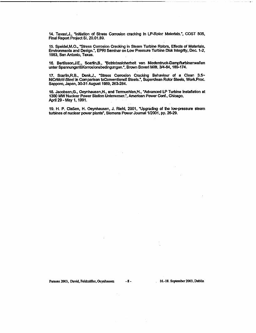
Stress Corrosion Crack Initiation
In high-purity water with a conductivity of < 0.2 pSlcm, only the quenched-and-temperedcondition, ILe., the hardness of the steel, influences initiation of stress corrosion cracking. Upto a 0.2% yield strength of 970 MPa, stress corrosion cracking did not initiate cracking In anyof the quenched-and-tempered conditions studied. Nor did It cause cracking in smooth ornotched test pieces at stresses above the 0.2% yield strength (Figure 5).57 This isIndependent of the purity of the steel. In high-purity water, those steels conventionally melted25 years ago perform just as well as high-purity steels made using the ESR process.6 Underhigh purity water conditions, even non-metallic Inclusions (such as A1203, MnS, etc.) In thesurface of the material do not act as crack Initiators and have no effect on stress corrosioncracking resistance. This holds true in both pure oxygen and oxygen-saturated water. Nolocalized, anodic dissolution on the material surface (pit formation) was observed underthese high-purity corrosion conditions.
Under quenched-and-tempered conditions the steels with a 0.2% yield strength > 1085 MPawere damaged by hydrogen-induced stress corrosion cracking (Figure 5).
Parsons 2003, David, Feldmfihler, Oeynhausen -2 - 16.48. September 2003, Dublin

Stress Corrosion Crack Propagation
The two phases, crack Initiation and crack propagation, must be looked at separately withstress corrosion cracking. As stated above, stress corrosion cracking does not Initiate Ineither smooth or notched specimens in high-purity water. However, stress corrosion doesresult in crack propagation in statically loaded fracture mechanics test specimens with verysharp, deep cracks In high-purity water.
Crack propagation results are shown In Figure 6. As with crack Initiation, there is a 0.2%yield strength threshold between 1000 and 1100 MPa above which the mechanism, andsubsequently the crack propagation rate, drastically changes. With 0.2% yield strengthbetween 650 and 1085 MPa, propagation rates for stress corrosion cracking are almostentirely Independent of strength. At a service temperature of 80C, a crack would, dependingon the materiars strength, propagate by 0.2 to 0.8 mm per year due to stress corrosioncracking.
Higher aggressiveness In the media only has a slight influence on crack propagation sincethe electrolyte In the crack Is almost decoupled from the surrounding medium and nearlyconstant electrolyte conditions are established at the crack tip.t 7
When the 0.2% yield strength exceeds roughly 1100 MPa, the crack propagation rateIncreases drastically by several powers of ten. In this strength range, hydrogen-Inducedcracking plays a decisive role during crack propagation.
In summary, whereas crack Initiation does not occur in high-purity water at 0.2% yieldstrength below roughly 1000 MPa, existing cracks will propagate also under high puritywater conditions due to stress corrosion cracking. Cracks which have Initiated In media withelevated conductivity can therefore continue to propagate even If high-purity water is presentoutside the crack.
Therefore the maximum allowable service stresses, to avoid stress corrosion crack Initiation,under different steam and water conditions must be defined.
Threshold Values to Prevent SCC Initiation
Our own results and data from the literature regarding studies of stress corrosion crackinginitiation in low-alloy quenched-and-tempered steels for steam turbine disks with 0.2% yieldstrength .1000 MPa are summarized and discussed below. The goal was to define stresslimits for the prevention of stress corrosion crack initiation as a function of the corrosivemedium.
The results in high purity water are summarized in Figure 7. 0 Since no stress corrosioncracking occurred, the limit stress for the prevention of crack initiation has beenconventionally defined as
Rsca (high-purity water) = 1.1
(Rs= [service stress/0.2% yield strength] = threshold value for preventing stress 2orroslon2rack initiation In rotor steels 0.2% yield strength <1000 MPa).Figure 7 also Includes results of stress corrosion crack initiation studies in condensingsteam.11- 3 These studies simulate conditions as can occur during operation in the region ofthe Wilson line. In this region, the condensate first forms on the surface of the material.Because of the coefficients of distribution, enriched concentrations of water-solubleimpurities In the water/steam cycle can occur here and cause pitting and crack Initiation.
Rsca (condensing steam) = 0.9
Similar Threshold curves as shown In Figure 7 were developed with data under moreaggressive corrosion conditions, such as
* condensing steam with crevice conditions 1
• water with gaseous Impurities S 10. 14
Parsons 2003, David, Feldmfliler, Ocynhausen -3- 16,18. September 2003, Dublin
* stagnant water without refreshing 4 10,14
This simulates strong increase in conductivity, which however Is not typical for normaloperating conditions. In these relatively aggressive media for low-alloy steel, high stressesare likewise required to produce stress corrosion cracking. The majority of test specimensexhibited no stress corrosion cracking with stress/0.2% yield strength 2 0.9.
Even In 30% NaOH solutions at 100 -1201C, the SCC-Initiation time is still clearly dependenton stress.'s17 Crack Initiation can therefore be precluded even during short disturbances ifthe associated service stresses remain below 50 to 60% of the 0.2% yield strength:
Rsoc (aggressive medium conditions) = 0.5 - 0.6
Figure 8 provides a summary of which stress limits must be exceeded to initiate stresscorrosion cracks in low-alloy quenched-and-tempered steels for steam turbine rotors with a0.2% proof stress c 1000 MPa. These stress limits are independent of the materialparameters chemical composition, steel purity, surface inclusions or similar metallurgicalfactors as can occur with heats produced using conventional industrial techniques. ThisIncludes surface Imperfections, such as mechanical notches, surface scratches andcomparable surface damage as can occur in singular cases despite careful processing andstringent quality assurance measures.
Use of Compressive Residual Stresses
One possibility for minimizing the stresses In critical regions of components is to inducecompressive residual stresses In the material surface. As part of a larger research project,various surface treatment processes were tested and refined with the objective of ensuringcompressive residual stresses of sufficient magnitude and depth of penetration withoutadversely affecting the surface. In the Siemens design the following methods are used toproduce surface compressive residual stresses:
Special Heat treatment process
During the heat treatment of the disks, a special water spraying treatment process is used toproduce compressive residual stresses in the surface area of the disk. The depth of thecompressive residual layer is adjusted in such a way that the machined and finished disk stillhas near surface compressive residual stresses of up to a depth of more than 50 mm (Figure9).
Machining and Shot Peening
To reduce the potential for stress corrosion cracking, the machining of the grooves and theentire rim section of the disks have been optimized to minimize residual tensile surfacestresses at any particular location. In nearly all cases after machining, a thin layer ofcompressive residual stresses exists. In the rotor sections which could possibly be exposedto stress corrosion, the disk surfaces, and certain sections of the blade attachment zone, areadditionally shot peened to produce deeper compressive surface residual stresses (Figure10).
Rolling of the keyways
After the shrinking of the disks, the keyway bores are drilled, followed by a rolling and honingprocedure. This honing process guarantees the maximum level of compressive residualstresses directly at the surface (FIgure 11).
Compressive Residual Stresses and Stress Corrosion Crack Initiation
Comparative studies of stress corrosion cracking were performed on test specimens withrolled and non-rolled bores. Tests were performed In sodium hydroxide to study themechanism of anodic crack tip dissolution while cathodic polarization was used to simulatethe mechanism of hydrogen-induced cracking. In the non-rolled test specimens, the stressesin the bore were on the same order of magnitude as the 0.2% yield strength. For the testswith compressive residual stresses, the test specimens were first pre-stressed to the 0.2%
Parsons 2003, David, Felindiller, Oeynhausen -4 - 16A 8. September 2003, Dublin

yield strength (simulating shrink fit), cold-rolled and then stressed again to establish a stresslevel In the surface of 40% the 0.2% yield strength. The established stresses weresubsequently significantly greater than those occurring In shrunk on disks with rolledkeyways under service conditions. The results of these studies are shown in Figure 12. Dueto the severe corrosion conditions, all of the test specimens which had not been rolledexhibited more-or-less deep stress corrosion cracking after short period. The test pieces withcompressive residual stresses produced by rolling were removed after approx. 4.000 -8.000 hours. Al the rolled specimens were free of SCC-cracks.
Crack Initiation did not occur In the rolled test specimens. Due to the rolling process, the totalsurface stress was below the limit for crack initiation Rscci = 0.5 - 0.6 (severe corrosionconditions).
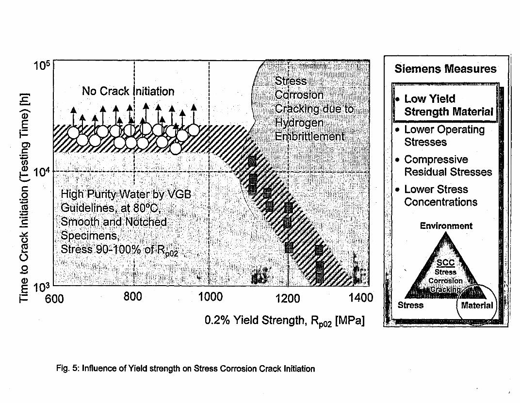
As mentioned above, the total service stresses In the keyways are much lower than in thetested, rolled specimens. Due to drilling and rolling after the shrinking process and the highcompressive residual stresses resulting from rolling, the total service stresses are stillcompressive. Moreover, the design avoids shrink fit stresses In the keyway area. Thegeometry of the shrink fit region is designed In such a way that the keyway Is open to theambient steam. That means steam or condensed steam continuously Is exchanged, thusstagnant or crevice conditions with higher conductivity are avoided (Figure 13).
Reduced operating stressesIn addition to the locally optimised design In the keyway area, the global geometry of thedisks has been designed to reduce all tensile surface stresses to the target level. Figure 14shows a typical tangential stress distribution of a first disk at the rated speed. Thesuperimposed stresses given by the advanced heat treatment of the disks, and the sum ofboth, are also shown In this figure.
Verification In the FieldFor many years, Siemens' original design of shrunk on disk rotors, as well as the advanceddisk design, have demonstrated and proven the quality of this technology. The total numberof fleet operating hours is more than 2,750,000, which have led to more than 40 million diskoperating hours, bearing In mind that each unit consists of two to three LP turbine elementswith six to ten disks each.The oldest rotors, which were never replaced, have been In operation for approximately225,000 operating hours , and the Inspections of the disks performed after more than200,000 hours showed no crack at all.The same encouraging result was gained In more than 660 disk inspections, with just asingle exception In which a SCC crack was detected, now more than 15 years ago.18
The subsequent investigations showed that small particles In the finished surface wereresponsible for the crack Initiation. This disk was manufactured more than 25 years ago, at atime when the reasons for SCC were not known In detail. The optimisation of the qualitycontrolled manufacturing process and the developed knowledge of SCC ensured theavoidance of similar events.Due to this Impressive operational record and the availability of new blade and seal designsfor improving the turbine efficiency, turbine modemisations were performed In order tooptimise the cost effectiveness of the plants with advanced disk technology.Excellent results were obtained in the German 1400MW nuclear power plant, Emsland, InMay 2000. '9 In only 16 days, two LP inner casings and rotors, Including re-work of the outercasing, were able to be fully completed. Additional 32MW showed the success of thismodemisation by the fact that the guarantees were fully met. It has to be noted that thisimprovement took place despite the fact that the size of the last stage blades remainedconstant.
Parsons 2003, David, FeldmOller, Oeynhausen -5- 16A B. September 2003, Dublin

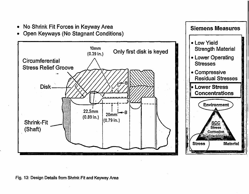
New ProductsMany of the turbines originally designed by Siemens have been modernised in order toimprove efficiency. Furthermore, products have been made available to improve non OEMturbines like In Figure 2 with the advanced disk design.Figure 15 shows the advanced shrunk on disk LP rotor, designed for Westinghouse LPturbines BB81 and BB281, Including all major design features described In this paper. TheseInclude the following factors:
* Compressive residual stresses by heat treatment, shot peening and rolling.* Optimised disk and keyway design to minimise tensile stresses.* Reduced number of disks and keys.
ConclusionThe Siemens shrunk on disk rotor technology has proven its reliability during long-termoperation periods exceeding 30 years. In addition, the advanced disk rotor design employsfurther protection measures that thwart the onset of SCC. Based on these design features,new products have been presented to the market which allow the use of this superiortechnology, to modemise the Siemens Westinghouse fleet, not to mention units built by otherturbine manufacturers.
Parsons 2003, David, Feldrnaller, Oeynhausen -6 - 16.48. September 2003, Dublin

References:
1. M. Deckers, D. Doerwald, 1997, 'Steam turbine low path optimizations for improvedefficiency", Power-Gen Asia '97, Singapore, September 9-11, 1997
2. EPRI Report NP-2429, *Steam Turbine Disk Cracking Experience", Volume I through 7,Research Project 1398-5, June 1982
3. Smiarowski, M. W., Green, R. C., wTurbine steam path retrofit project completed at PECOnuclear's Limerick generating station units I and 2", PowerGen International, New Orleans,1999.
4. J. A. Bartos, M. S. Gorski, L. E Olah,. M. W. Smiarowski , 'Susquehanna steam electricstation turbine retrofit/generation uprate: Decision factors for long term reliability andImproved performance" PowerGen International, Las Vegas, 2001
5. EngelkeW., Schleithoff,K, Jestrich,HA., Termuehlen,H., 'Deslgn,Operating andInspection Considerations to Control Stress Corrosion of LP Turbin Disks., American PowerConference, Chicago, Illinois, April 18-20,1983.
6. DavidW., SchlelthoffK, Schmitz,F., "SpannungsrlBkorrosion in hochreinem Wasser von3-3,5% NiCrMoV-Verg~tungsstAhlen fOr Dampfturbinen-Scheiben und -Wellen.', Teil I und2, Mat.-wiss. u. Werkstofltech. 19,43-50, 95-104, 1988.
7. Oeynhausen,H., Rottger,G., EwaldJ., SchleithoffK., Termuehlen,H., 'ReliableDisk-Type Rotors for Nuclear Power Plants.", American Power Conf., Chicago, April 27-29,1987.
8. DavidW., SchleithoffK, SchmitzF., EwaldJ. , OStress Corrosion Cracking Behaviour ofTurbine Rotor Disk Materials, Crack Initiation and Propagation, Measures to Prevent SCC.',High Temperature Materials for Power Engineering 1990, September 24-27, 1990,Liege-Belgium, 577-588.
9. DavidW., R6ttgerG., SchleithoffK., Hamel,H., TerniUhlen,H. , 'Disk-Type LP TurbineRotor Experience.", Presented at the 1993 International Joint Power Conference, KansasCity, Missouri, Published by the ASME Power Division.
10. Termuehlen,H., SchleithoffK., Neumann,K. , "Advanced Disk-Type LP Turbine Rotors.',EPRI Workshop, Stress Corrosion Cracking in Steam Turbines, Charlotte, North Carolina,October 10-11, 1990.
11. Roberts,B.W., Greenfield,P. , 'Stress Corrosion of Steam Turbine Disk and RotorSteels.!, Corrosion-NACE, Vol 35, No. 9, September, 1979,402-409.
12. Holdsworth,S.R., Bumell,G., SmfthC., "Factors Influencing Stress Corrosion CrackInitiation In Super Clean 3.5NiCrMoV Rotor Steel.", Superciean Rotor Steels, Work. Proc.Sapporo, Japan, 30-31 August 1989,299-319.
13. Holdsworth,S.R., Bumell,G., "Stress Corrosion Crack Initiation in LP Turbine RotorSteels.", High Temperature Materials for Power Engeneering, Liege, Belgium, 2427 Sep.1990, 555-566.
Parsons 2003, David, Fedrdmlkler, Oeynhausen -7 - 16.48. September 2003, Dublin
14. TavastJ., *Initiation of Stress Corrosion cracking In LP-Rotor Materials.", COST 505,Final Report Project SI, 20.01.89.
15. SpeidelM.O., 'Stress Corrosion Cracking in Steam Turbine Rotors, Effects of Materials,Environments and Design.', EPRI Seminar on Low Pressure Turbine Disk Integrity, Dec. 1-2,1983, San Antonio, Texas.
16. Bertilsson,J.E., Scarlin,B., 'Betriebssicherheit von Niederdruck-Dampfturbinenweflenunter SpannungsrinKorrosionsbedingungen., Brown Boveri Mitlt. 3/4-84, 169-174.
17. Scarlin,R.B., DenkJ., 'Stress Corrosion Cracking Behaviour of a Clean 3.5-NiCrMoV-Steel In Comparison toConventionell Steels.'. Superclean Rotor Steels, Work.Proc.Sapporo, Japan, 30-31 August 1989, 263-284.
18. JacobsenG., Oeynhausen,H., and Termuehlen,H., 'Advanced LP Turbine Installation at1300 MW Nuclear Power Station Unterweser.', American Power Conf., Chicago,April 29- May 1, 1991.
19. H. P. Clafen, H. Oeynhausen, J. Riehl, 2001, 'Upgrading of the low-pressure steamturbines of nuclear power plants'. Siemens Power Journal 1/2001, pp. 26-29.
Parsons 2003, David, Feidmiller, Oeynhausen -8- 16.48. September 2003, Dublin

DISC CRACK LOCATIONS
0 Rim Axial-CircumferentialOrientation (Type t)
( Rim -- Axial-RadialOrientation (Type d)
0 Web -Axial'ClecumferentialOrientation
( Web-oAxia[l-RdialOrientation
I CRACKS
DISC 0DKeyway -- Axial-RadialOrientation
Sore Surface -- AxialiRadialOrientation
0D.b
v'-em c
CRACK ORIENTATiONS-
SHAFT^a-Radial
L- Circumferential
- Axial
M___
Fig. 1: SCC Problems published in the past 2
I

Shrunk-on Disk Rotor
7D7rL�F1[ I.. _. ... _ .. _11 * '¢ ....1 E At t~~~~I .. . .
Monoblock Rotor
Fig. 2: Advanced Disk Rotors Replace Various Rotor Designs
m

Six-Disk Rotor - Since 1995 Fig. 3: Development of Disk Rotors

Environment
Stress Material
Fig. 4: Stress Corrosion Cracking (SCC) and Prevention
1 05 |,3
No Crack Initiation ,=_ 1O i : j k j K j il T i i j K * i i , os i q na) JF 4K A s AL X T~~~~~~~~~~~~ I 1 -
F g SE 4 #4 S~~~~~~~~~~~~~~~
*10
0 10 gb-P--- iWf -"--"r
o ; High Purity ter by VG iGudelnines, at 800 C,
cSmooh0 Yeandd SNttche R
.9 t
E 103600 800 1000 1200 1400
0.2% Yield Strength, R~0 (MPa]
Fig. 5: Influence of Yield strength on Stress Corrosion Crack Initiation

Siemens Measures
10-7
10-8
10-9
10-10
10-11
10-12
-by Low YieldStrength Material
* Lower OperatingStresses
* CompressiveResidual Stresses
* Lower StressConcentrations
Environment
Stress ICorrosion0-Crackinq,
600 800 1000 1200 1200
0.2%-Yield Strength [MPa]
Fig. 6: Influence of Yield Strength on Stress Corrosion Crack Growth Rate

A
=4 -I,-,+Siemens Measures
1,2 e * Low Yieldx/)
___A M Strength Material
._c 1_(High Purity Water) * Lower Operating- -- - -Stresses
NO,8 S (Condensing Steam) * Compressiveo 0,8 - SkiXO Residual StressesU) . Lower Stress4 0,6 II Concentrations
0,4 EnvironmentHigh ,t at r = ; 0 No
0,2 ~ E Con'den~singSem9 0 ,~oSO______Co~~nde'singSem5 0 ,SC ___tes
0 _ _ _ _ _ _ _ _ _ _ _ _ _ _ _ _ _ _ _ _ _ _ _ _ ~~~~~~~~~ ~~Corrosion
0 10.000 20.000 30.000 40.000 50.000 60.000 aterialTesting Time [h]
Fig. 7: Stress Corrosion Crack Initiation Tests on Turbine Disk Steels, 0.2%-Yield Strength < 1.000 MPa

-
Siemens Measures.
* Low YieldStrength Material
I1Lower OperatingStresses
1.2
i -Severe Corrosion lt; :
; >;1<& >0.5 - 00.6 I- "f
No Pits* Compressive
Residual Stresses* Lower Stress
Concentrations[L
0.5
0.0
* k
. ..
.Steel Surface with Inclusions,;-Mechanical Scratches,
i::,,.: FavourableCrevices
P.. nothing RI,~~~~~al
Fig. 8: Stress Corrosion Crack Initiation Threshold Value RsccI for Turbine Disk Steels, 0.2%-Yield Strength < 1.000 MPa
I

Siemens Measures
* Low YieldStrength Material
* Lower OperatingStresses
. CompressiveResidual Stresses
* Lower Stress* Concentrations
Environment
Water Spraying ProcessDuring Disk Heat Treatment
Compressive Stress Area 5060m
Fig. 9: Compression Residual Stresses Produced During Heat Treatment Process

Distance from Disk Surface [mm] Siemens Measures0 4
r"
IO4-'
_ -200
nF -300-m 00a)
Ca)
I1 III I I I II !I lV
4) 0:2 0:4 0:6 0:8
-i~~~~~~~k
0~~~~~~ - ~ ~ ~ ~ d
0~~~~~~~~~~~~~~~~~~~~~~~~~~~~~~~~~~~~~~~~~~~~~~~~~~~~~~~~~~~~~~~~~~~~~~~~~~~~~~~~~~~~~~~~~~~~~~~~~~~~~~~~~~~~~~~
0~~~~~~~~~~~~~~~~~~~~~~~~~~~~~~~~~~~~~~~~~~~~~~~~~~~~~~~~~~~~~~~~~~~~~~~~~~~~~~~~~~~~~~~~~~i
I r~~~~~7
4 -~~~~~~~~~~~1 7 [I,
0 * Low YieldStrength Material
* Lower OperatingStressesC Compressive
!Residual StressesI
i* Lower Stress
Concentrations
-500-
-600-
Fig. 10: Compression Residual Stresses Produced by Shot Peening Process

Distance from Disk Surface [mm] Siemens Measures0 L..r II
-
:ii
-100
-200
-300
-400
-500
-600
-700
-800
* ~~~~~ ~ ~ ~ ~ ~~TT
, * ,V50 1,00
* After rolling, this area of low compressivestresses has to be removed by honing
-T - - - - - - - - - - - - - .: -:U~~~ ~~~ ~~~ ~~~ ~~~ ~~~ ~~~ ~~~ ~~~ ~~~~~~~~~~~~~~~~~~~~~~~~~~~~~~~~~~~~~~~~~~~~~~~~~~~~~~~~~~~~
U~~~~~~~~~~~~
U~~~~~~~~~~~~~~~~~~~~~~~~~~~~~~~~~~~~~
--U- -~~~~~~~~~~~~~~~~~~~~~~~7-
* '' . :
:U 1.: E~:':.;','f' ,. S4':. S:: . f
* : ' . ; ' ''U' . ' ,.. ',: X e..' - '';,* ... . .U.f i , ,s i..:___ U , ,_____________ S_ ,
** : ' '-- ; -' :- f '' : .- ,, . '' ' i. '; , ,-',-I;'"'iE '.S ;"' -. ';", ' S4
U ; ! i E', '' o ' l<' r iS L E1 [ f n. ' S / 4-. Ii . ... '' ' :'i','|i ., t' ,,i
U :, : ~;, .; ,:>,. .........,]..... ;.t,ra . y '§ ' §5 ' i ' ;1 F ; Xjj 2 " i , , v: : ! / T ; . 0i ., ? ... , j ....
_ 'i_ W -U JStXXL.Uir t 'i ^ '' iH 'g, :: i1 ; , ,0,: ; , ,/ ; -
NJCa< ;;j!, r_;wriilis! j__A. .;'._ :_-~. ;........i ^=at......:.:_
U E -' 1 Ei<4 r 10 -
,;E a i ,b, .', ; ; ..,. T ool' ,'*z'...... .. [, 1.';. '.':H ''4_s'
U '^lt> ';0''h>'j,>>0:!0. 0M:0; ;0:.ii
50 * Low YieldStrength Material
* Lower OperatingStresses
. CompressiveResidual Stresses
* Lower StressConcentrations
EnvironmentA
Fig. 11: Compression Residual Stresses Produced by Rolling Process

30 Siemens Measures.
25
20
15
10
5
0
* Low YieldStrength Material
. Lower OperatingStresses
I CompressiveResidual Stres!
* Lower StressConcentrations
Environment
j0 2.000 4.000 6.000 8.000 10.000
Testing Time [h]
Fig. 12: Stress Corrosion Crack Initiation - Modified CT-Specimens With Residual Compression Stresses (Rolled Bore)
0No Shrink Fit Forces in Keyway AreaOpen Keyways (No Stagnant Conditions)
Siemens Measures
10mm(0.39 in.) Only first disk is keyed
CircumferentialStress Relief Groove
Disk
Shrink-Fit ____
(Shaft)
* Low YieldStrength Material
* Lower OperatingStresses
* CompressiveResidual Stresses
I Lower StressConcentrations
al
Fig. 13: Design Details from Shrink Fit and Keyway Area

Caused by CentrifugalForces and Shrink Fit
Residual Stresses by HeatTreatment i
Superimposing of allStresses
Fig. 14: Tangential Stress Distribution at Rated Speed (N/mm 2)
S1 It
I SI
I U- I
Fig. 15: Modernisation of a Westinghouse BB81/281 LP Turbine with Advanced Disk Rotors
Report No.: CT-27332 Revision 2 Page: I of 27
Handling: Restrictive
Siemens Technical ReportSublectfIT1e
Missile Probability Analysis
CT-27332 Revision 2Place Date
Orlando, FL 8/8/2003Department Tel. SignatureAuthor(s)
Dr. A. Bagaviev S321 3765
Pr13
BB81/281 13.9 m
P. Bird S326 407-736-4686
Signature for Release by Dept. Concerned Signature for External Release by(for Contents. Harding, Distribution) Sales & Marketing Dept (Not
Required for Approval Documents)
AL: ECCN:
Handlina Instructions
RestrictiveExdort Classdcalkln)I Pm.-Code UA or DCC Contents Code I I Doc. dent. No.
Summary* Pages of Text: 27 Appendices:
Missile probability analysis is presented for the Siemens 13.9m2 retrofit design of LP turbines. Thesemodem upgraded designs are used in various applications including replacement of Westinghouseoriginal BB81 and BB281 nuclear LP rotors and internals.
Results of the analysis indicate that the missile probabilities remain well below the Nuclear RegulatoryCommission (NRC) limits of 1 E-4 for a favorably oriented unit and 1 E-5 for an unfavorably orientedunit for up to 100,000 operating hours between disc inspections providing that no cracks are detectedin the discs. Previously, in the submittal for the Limerick Unit 16', the NRC had approved the missileanalysis methodology for 10 years, which is about 87,600 operating hours. This report justifies exter-nal missile probabilities out to 100,000 operating hours In comparison with the NRC limit. Furthermore,test frequency for the main turbine stop and control valves continues at once every 3 months (quar-terly), as previously approved.
') bt Technical Reports add key words (max 12) at the end of the Surmrwy and arter Export Classification
Distribution (addU.io., ionly unwnaryIsdistnbutedforInformation): adex Veri. Dete pages Mai of Initials for
James McCracken S326Jim Auman S326Andreas Feldmueller S327
Siemens AG * Power Generation Transmittal. reproduction dasserination end/or editing d this document as well asutilization of Its contents and con'rnujnlcation thereof to others without express authotizationare prohibited. Offenders will be held liable for payment of damages. All rights created bypatent grant or registration of a utility model or design patent are reserved.
H30-K5314-X-X-76W Berichl, engl. 2001-09 D97 C:\data'documnts\13.9m2 Missile Repon Rev2.doc

Report No.: CT-27332 Revision 2 Page: 2 of 27
Handling: Restrictive
Revisions
No. Date Description
0 February 26, 2003 Original issue.
1 June 6, 2003 Editorial change to add units to Figures 6 & 7.
2 August 8, 2003 Changes were made to be in full compliance with theNRC Acceptance Letter18 and Safety Evaluation Report"'.
Siemens AG * Power Generation Transmital reproduction, dsserninalon andPor editing of this document as well asutilization of Its contents end conmunication thereat to others without ePress authorizationare prohibited. Offenders Wilt be held fiable tor payment of damages. All rights created bypatent grant or registration of a utility nodel or design patent are reserved.
CAdataidocumnts\13.9n2 Missile Report Rev2.docH30-K5314-X-X-7600 Bericht. engi. 200149 097
Report No.: CT-27332 Revision 2 Page: 3 of 27
Handling: Restrictive
Contents
I INTRODUCTION ........................ 4
2 ANALYSIS METHODOLOGY .................... . 4
2.1 NRC Criteria for Missile Probability .............................. 5
3 INTEGRITY ANALYSIS ........................ . ... 8
3.1 Stress Corrosion Cracking (SCC). .. 8
3.2 FaIlure Assessment Procedure.......................................................................................................... 10
3.3 Stress A-11-11-PAI.A.3.. iy.~.................................................................. 11
3.4 Probabilistic Fracture Mechanics Analysis ............................................ 143.4.1 Load.153.4.2 Crack Branching Factor .153.4.3 Fracture Toughness .153.4.4 Yield Strength .163.4.5 SCC Growth Rate .163.4.6 Initial Crack Size .163.4.7 SCC Initiation Model .16
4 PROBABILITY OF CASING PENETRATION FOR SPEEDS UP TO 120% OF RATEDSPEED ...................................... 18
4.1 Criterion for Casing Penetration Given a Disk Burst ............................................ 184.1.1 Initial Energy ............................................ 194.1.2 Energy Dissipation ............................................ 194.1.3 Calculation Results .............................................. 19
5 OVERSPEED EVENT ....................................... 19
6 PROBABILISTIC SIMULATION RESULTS ....... .............................. 21
7 CONSERVATISM IN METHODOLOGY ...... ............................... 25
8 REFERENCES . .................................... 26
Siemens AG * Power Generation Transmittal, rpodction, dissenination andtcr adting f this document as well asutilization ol its contaens and onmunlcation thereof to oMers Without express *uthodlzab onar proNbited. Offenders Alt be held liable for payment of damages. All ights created bypatent grant or registration of a utility model or design patent are esewved.
H30-K5314-X-X-7600 Berdcht, engi. 2001-09 D97 C.NdateNdocurrintsM 3.9m2 Missile Report ReQ.doc
Report No.: CT-27332 Revision 2 Page: 4 of 27
Handling: Restrictive
1 Introduction
2 Analysis Methodology
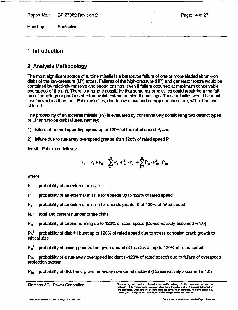
The most significant source of turbine missile is a burst-type failure of one or more bladed shrunk-ondisks of the low-pressure (LP) rotors. Failures of the high-pressure (HP) and generator rotors would becontained by relatively massive and strong casings, even if failure occurred at maximum conceivableoverspeed of the unit. There is a remote possibility that some minor missiles could result from the fail-ure of couplings or portions of rotors which extend outside the casings. These missiles would be muchless hazardous than the LP disk missiles, due to low mass and energy and therefore, will not be con-sidered.
The probability of an external missile (P1) is evaluated by conservatively considering two distinct typesof LP shrunk-on disk failures, namely:
1) failure at normal operating speed up to 120% of the rated speed Pr and
2) failure due to run-away overspeed greater than 120% of rated speed P.
for all LP disks as follows:
N NPI = Pr +Po = IPrPrPr+1 9 3
1=1 1=1
where:
P1 probability of an external missile
Pr probability of an external missile for speeds up to 120% of rated speed
P) probability of an external missile for speeds greater that 120% of rated speed
N, i total and current number of the disks
Pir probability of turbine running up to 120% of rated speed (Conservatively assumed = 1.0)
P2rI probability of disk # i burst up to 120% of rated speed due to stress corrosion crack growth tocritical size
P3rI probability of casing penetration given a burst of the disk # i up to 120% of rated speed
P10 probability of a run-away overspeed incident (>120% of rated speed) due to failure of overspeedprotection system
P20' probability of disk burst given run-away overspeed incident (Conservatively assumed = 1.0)
Siemens AG * Power Generation Transmittalit, romdcdon, dsserninstion andfor ediing of this document as wel asSiemens AG. Power Generation 04Lilizaio o It cntetsan com iatont rcAt oter wh~ exrs uhrztoare prchibited. Offenders will be held liable for payment of damages. All dights created bypatent grant or registration of a utility model or design patent are reserewd.
H30-K5314-X-X-7600 Berlchil ngi. 2001.09 D97 C:datadomwnts\13.9rn2 M ssile Repon Rev2.doc

Report No.: CT-27332 Revision 2 Page: 5 of 27
Handling: Restrictive
P30i probability of casing penetration given a burst of the disk # i at run-away overspeed (Conserva-tively assumed = 1.0)
The overspeed probability P10 is a function of the maintenance and test frequency of the speed controland overspeed protection system.
The probability of normal operating speeds up to 120% of the rated speed is assumed to be 1.0. It isalso conservatively assumed that, given the overspeed protection system fails the probability of a disk# i burst and that of casing penetration of the burst fragments are also 1.0 each for all disks.
Finally, the expression for the external missile probability could be rewritten as:
N
PI Pr + Po = P2r -P~r + Pro
Therefore, the only remaining values that need to be quantified are P2a, P3r' and P10 .
The methodology for evaluation these probabilities is described in the following sections.
2.1 NRC Criteria for Missile Probability
The US Nuclear Regulatory Commission (NRC) has defined criteria governing nuclear steam turbinestart-up, continued operation and shut down requirements.
Two power plant layouts, namely unfavorable and favorable orientations, have been identified asshown in Fig. 1.
Siemens AG * Power Generation Transittal, reprdction, dssenination and/or diting f this document as well asutilization of Its coetents and cormunication tered to others vdthout express euthorezationare prohibited. Offenders will be held lBable for payment of damages. Al vtgtts created bypatent grant or registration of a utility model or design patent are reserved.
C dataedocumnts~t3.9m2 Missile Report Rev2.docH30-K5314-X-X.7600 Berciht, Wnd. 2001-09 097

Report No.:
Handling:
CT-27332 Revision 2
Restrictive
Page: 6 of 27
Favorable Orientation Unfavorable Orientation
Fig. 1 Nuclear turbine unit orientation relative to reactor building
Siemens AG - Power Generation
H30-K5314-X-X-7600 Beridnt, *ngi. 2001409 097
Trannmittal, reproduction, dssernination andtor eadng of this docurnent as well asutlizaton of its contents and conmunication tnered to others witt express authorizationwre prohibited. Offenders YAII be held liable for payment of damages. Ai dights created bypatent grant or registration of a utility model or design patent are reserved.
C:data\documnts\13.9rn Missile Report Rev2.doc

Report No.: CT-27332 Revision 2 Page: 7 of 27
Handling: Restrictive
Table 1 shows the allowable limits for the probability of external missile from the steam turbine - gen-erator unit (P1) for start-up and continued operation. The overspeed protection system test with main-tenance frequencies and disk inspection intervals must be selected to ensure that these criteria aresatisfied.
Favorably Oriented Turbine Unfavorably Oriented Turbine Required Ucensee Action
This is general, minimum reli-(A) Pi < 104 P1 < 105 ability requirement for loading
the turbine and bringing thesystem on line
If this condition is reached dur-ing operation, the turbine maybe kept in service until the next
(B) 104 < P., < 103 105 < p1 < 104 scheduled outage, at whichtime the licensee is to take ac-tion to reduce P1 to meet theappropriate A criterion beforereturning the turbine to service
If this condition is reached dur-ing operation, the turbine is tobe isolated from the steam
(C) 1le < P. < 10-2 104 < p103 supply within 60 days, at which
time the licensee is to take ac-tion to reduce PI to meet theappropriate A criterion beforereturning the turbine to service
If this condition is reached dur-ing operation, the turbine is tobe isolated from the steamsupply within 6 days, at which
(D) 10-2 < P1 time the licensee is to take ac-tion to reduce P. to meet theappropriate A criterion beforereturning the turbine to service
Table 1 Turbine System reliability Criteria (NRC GUIDE NUREG-1048 Table Ul)
Siemens AG * Power Generation Trsnarnitel, reproduction, dsseminaifon and/or editng of this document as well asutilization o Its contents and conmmunication thereof to others without )press auhrzaionWe proibtited. Offenders will be held lle for payment of damages. All uights created bypatent grant or registration ofe utility model or design patent aem reserved.
H30-K5314-X-X-7600 Bericht, engl. 2001-09 D97 C.Adala\docurnntsX13.9rn2 Missile Report Rov2.doc

Report No.: CT-27332 Revision 2 Page: 8 of 27
Handling: Restrictive
3 Integrity Analysis
3.1 Stress Corrosion Cracking (SCC)
When materials such as used in turbine disks (Fig. 2) are exposed to sustained high tensile stress andan aggressive moist environment, cracks initiate and grow with time.
Fig. 2 Rotor with shrunk-on disks
This phenomenon is known as Stress Corrosion Cracking (SCC). Low pressure steam turbineshrunk-on disks with high stresses at the bore are susceptible to stress corrosion cracking. As a crackinitiates and then grows with operating time, the stress intensity factor associated with the crack alsoincreases. Finally, when the stress intensity factor approaches and equals the critical stress intensityfactor for the material which is the fracture toughness property, a disk burst condition occurs. Alterna-tively, a critical crack corresponding to the material fracture toughness is calculated, and a burst con-dition is considered to occur when the crack size approaches and equals the critical crack size.
Siemens has conducted extensive studies into the SCC behavior of materials used for rotor disks. Theresults of the investigations can be summarized as follows.
SCC consists of an initial crack initiation period in which pitting or cracks are formed which is followedby a crack growth period.
Siemens AG * Power Generation Transnmttal, reproozcflon, disserination mndlor editing of this docurnent as well asutilization of Its contents and oormnunication thered to others without epress authorizationare proibited. Offenders will be held lable for payment of damages. All eights created bypatent grant or registration d a utility model or design patent are reserved.
H30-K5314-X-X-7600 Befcht, nI. 2001-09 097 C'data\doctjmrdsNl 3.gff&2 Missile Report Rav2.doc

Report No.: CT-27332 Revision 2 Page: 9 of 27
Handling: Restrictive
0
Stress Intensity factor Kq Cc
Fig. 3 Schematic dependency SCC growth rate versus stress Intensity factor
Fig. 3 shows schematically the SCC growth rate as a function of the applied stress intensity factor K,which exhibits three distinct regions. Region I shows that no crack growth occurs below a thresholdvalue of Kiscc (typically of the order of about 20-30 MPa-m). During region 11 SCC growth rate is vir-tually independent of the stress intensity level, until K, approaches the material fracture toughnesslevel. Then in region IlIl SCC growth rate increases rapidly leading to fracture.
Impurities in steam, conditions promoting flow stagnation such as crevices, steam condensation, ratioof stress to yield strength and level of yield strength significantly influence the potential for SCC.
In high purity water with a conductivity of < 0.21iSlcm, SCC initiation is Influenced only by the quench-ing and tempering process which establishes the material's yield strength value. If the yield strengthexceeds approximately 1085 MPa (157 ksi), the material becomes susceptible to SCC due to hydro-gen embrittlement. Up to this threshold, no stress corrosion crack initiation occurred even when oper-ating stress exceeded the yield strength in notched specimens. This result is also not affected by thepurity of steel. Under high purity water conditions, even nonmetallic inclusions (e.g. A1203, MnS etc.)do not act as crack starters at the material surface. Such inclusions do not influence the resistance tostress corrosion cracking. This even applies to water with low oxygen content as well as to oxygensaturated water. Pit formation was also not found under these corrosive conditions.
Siemens AG * Power Generation Transntal, reproduction, dssemntation end/or editing of this document as wall asutilization of its contents and conTnunication tareo to others without express euthorizationare prohitted. Olfenders will be held liable for payment of damages. All mights created bypatent grant or registration of a utility model or design patent are reserved.
H3D-K5314-X-X7600 Beriht, engi. 2001-09 D97 0-14ft\dOcunM\13.9m2 Missile Report R&v2.dDc

Report No.: CT-27332 Revision 2 Page: 10- of 27
Handling: Restrictive
12 -
0. -
0.5 _
0.0 _
Fig. 4 Stress corrosion crack Initiation of LP turbine rotor steels with 0.2% offset yield strengths < 1000 MPa (145 ksi)
Findings from extensive testing, power plant experience and review of literature leads to Fig. 4. Foryield strengths less than 1000 MPa, this figure shows at what operating stress to yield strength ratios,stress corrosion crack initiation can be expected for specific environment conditions. As shown in thefigure, an improvement of the operating environment permits high stress levels up to and above theyield strength level of the material. The diagram also reveals that with stress levels below 60% of theyield strength, stress corrosion cracking has not occurred even under severe corrosion conditions.
3.2 Failure Assessment Procedure
Because of the large disk bore diameter, defects on the bore surface can be treated using the basicfracture mechanics model for the case of a semi-elliptical surface crack in an infinite plate subjected totension loading aeff. This leads to the expression for the critical crack size a&c at which a disk wouldrupture due to brittle fracture (within the "small scale yielding" approach) given by:
Q __C 2
1.21 -u aef
where:
1<4c = Fracture toughness,
Siemens AG - Power Generation Tranrnrtla, rproduction dssernination andror edfing of this document as well astulllzaion of Its contents and conmrunication thereof to others without elress authorizationare prohlbited. Offenders vil be held Kable for payment of daneges. All rights created bypatent grant or registraton of a utility model or design patent are reserved.
H30-K5314-X-X-7600 Sericht. W4g. 2001-09 D97Cdtsouma\3m2 salRertev.cC.Adata\docurrrft\13.9rn2 Mssile Report Rev2.doc

Report No.: CT-27332 Revision 2 Page: II of 27
Handling: Restrictive
r.ff = Effective tangential bore stress due to the combined action of centrifugal loads and residualcompressive stresses (manufacturing) corresponding to the Fig.5.
Fig. 5 Fracture mechanics model
The crack shape parameter Q is a combination of the square of the complete elliptical integral of thesecond kind and "small scale yielding" correction:
0 = E(k) 2 1Cry
It can be for computational reasons approximated by the expression:
a 1'650 = I+ 1.464.
( c-0.212. CT
tcFY
2
3.3 Stress AnalysIs
The finite element analysis of the rotor with the shrunk-on disks (Fig. 2) was conducted to determinethe temperature and stress distribution due to the combined effect of shrink fit, thermal and centrifugalmechanical loads. The disk material is 26NiCrMoV1 4-5.
Temperature (Fig. 6) and tangential stress (Fig. 7) distributions in the disks are computed using acommercial Finite Element Code ABAQUS [9]. All appropriate loading conditions must be consideredin order to obtain the appropriate stress distributions for input to the fracture mechanics evaluation inthe location of interest.
Siemens AG - Power Generation Transnittal, reproduction, dissentination andlor odiing of this document as well asutilization of ts contents and comrmnication thereof to others without express authouiastonare prohibited. Offenders will be held eable for payment of damages. All rights created bypatent grant or registration of a utility model or design patent are reserved.
H30-K5314-X-X-7600 Berchl. Wel. 2001409 D97 CAd9la\documrft\1&9ni2 Missile Report Rev2.doc

Report No.: CT-27332 Revision 2 Page: 12 of 27
Handling: Restrictive
2.41+002
2.28+002
2.14+002
2.01+002
1.87+002
1.74+002
1.60+002
1.47+002
1.33+002
1.20+002
1.06+002
9.27+001
7.91+001
6.56+001
5.21+001
3.86+001
Fig. 6 Temperature distribution(Units In Degrees C)
Siemens AG - Power Generation Trmnsirnital. reprodction, dsserrination andlor editing ol this document as well asutilization of Its contents and conuinlrcalbon thereot to others wAtho express authodzationare prohibited. Offenders wil be held lable for payment of damages. All dghts created bypatent grant or regIstration of a utility modal or design patent are resarded.
C:dataNdocumtws\13.9r2 Missle Report Rev2.docH30-K5314.X-X-7600 BeWlcht eWi. 2001-09 D97

Report No.:
Handling:
CT-27332 Revision 2
Restrictive
Page: 13 of 27
6.33+002
5.66+002
4.98+002
4.31+002
3.64+002
2.96+002
2.29+002
1.62+002
9.41+001
2.68+001
4.06+001
-1.08+002
-1.75+002
-2.43+002
-3.10+002
-3.77+002
Fig. 7 Tangential stress distribution(Units in MPa)
Fig. 8 shows schematically the blue-colored compressive stress region (the width about 50 mm) andred-colored tensile stress region in the disk after special heat treatment during manufacturing. Thecorresponding distribution of the residual stress is presented as a brown line. The tangential stressdistribution at 20% overspeed near the disk bore at the maximal stress location is shown as a red line.The combined effective stress distribution is presented as a dashed blue line.
Siemens AG - Power Generation Transnittal, reproduction, dsserrination and/or dting of this docunent as well asutlization of Hs contents and coimmunication thereof to others vAthout express autoization
re prohibited. Oftenders vAl be held liable for payment of damages. All dights created bypatent grant or registration ola utility nxdel or design patent are reserved.
H30DK5314-X-X-7600 Beriht. eng. 2001409 D097 C.Adata\documnts\1&9rn2 Mesita Report Re&doc

Report No.: CT-27332 Revision 2 Page: 14 of 27
Handling: Restrictive
520
-~~~~~~~~~I-
280 i--~
ra 12
A;120 - -1 - -I"L . _.
0 20 40 60 60 100 120 140 160 1 200
Distance from the bore surface, mm
Fig. 8 Tangential (at 1209% of rated speed), residual and effective stress distribution In the disk #1
3.4 Probabilistic Fracture Mechanics Analysis
For probabilistic computations, Siemens has developed a numerical Monte-Carlo simulation code. Asa failure condition the brittle fracture mode is assumed:
t
acr(Kbvy,a.,k)•ai +fJa(cy,T)dt.0
Where:
acr = Critical crack size,
a = Current crack size,
ai = Initial crack size,
t = Operating time duration,
= Crack shape factor (crack depth to crack length ratio),
Kc = Fracture toughness,
Siemens AG * Power Generation Transmittal, prion, dsserninwion "aor dting of thSs document s well asutilihton of its contents and commnication thaered to others Bout expresss hlanionare plotibmited. Oflenders will be had liable or paymient of damages. Ail Ights created bypatent grant or registration of a utility model or design patent are reserved.
H30-K5314-X-X-7600 Bericht. end. 2001149 D97 C:Xdata\documts\13.9m2 MAssile Report Rev2.doc
Report No.: CT-27332 Revision 2 Page: 15 of 27
Handling: Restrictive
k = Branching factor,
a = Applied load due to tangential stress at bore,
ay = Yield strength, and
T = Temperature.
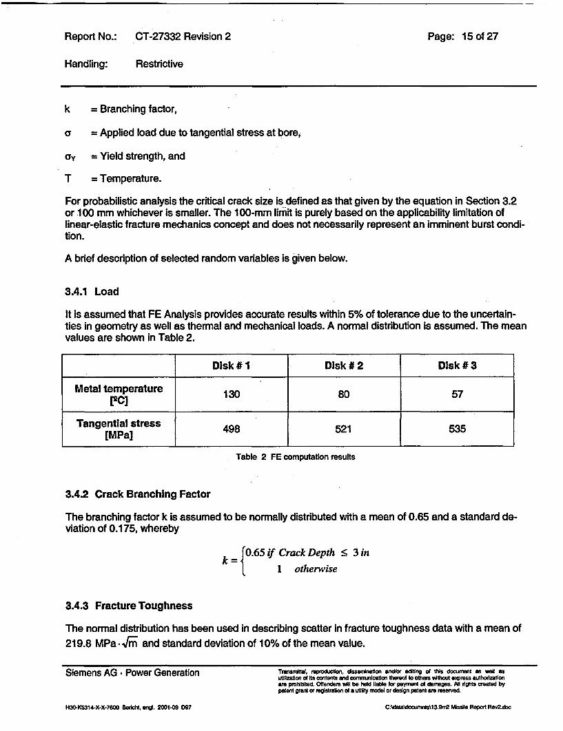
For probabilistic analysis the critical crack size Is defined as that given by the equation in Section 3.2or 100 mm whichever is smaller. The 100-mm limit is purely based on the applicability limitation oflinear-elastic fracture mechanics concept and does not necessarily represent an imminent burst condi-tion.
A brief description of selected random variables is given below.
3.4.1 Load
It is assumed that FE Analysis provides accurate results within 5% of tolerance due to the uncertain-ties in geometry as well as thermal and mechanical loads. A normal distribution is assumed. The meanvalues are shown in Table 2.
Disk # 1 Disk # 2 Disk # 3
Metal temperature 130 80 57
Tangential stress 498 521 535[M Pa]_ _ _ _ _ _ _ _ _ _ _ _ _ _ _ _ _ _
Table 2 FE computation results
3.4.2 Crack Branching Factor
The branching factor k Is assumed to be normally distributed with a mean of 0.65 and a standard de-viation of 0.175, whereby
k 0.65 if Crack Depth < 3 in1 otherwise
3.4.3 Fracture Toughness
The normal distribution has been used in describing scatter In fracture toughness data with a mean of219.8 MPa -.5- and standard deviation of 10% of the mean value.
Siemens AG * Power Generation Transmmtta, reprodiction, dsserination and/or editing of this document as weall asutilization of Its contents and Conunication thereof to others without express authorizationare prohibited. Offenders wil be held liable for payment od damages. Ail rights created bypatent grant or registration af a utility model or design patent are reserved.
H30-K5314-X-X-7600 Bericht, engd. 2001-09 097 CAd&ta\documms\13.9m2 Missile Report Rev2.doc

Report No.: CT-27332 Revision 2 Page: 16 of 27
Handling: Restrictive
3.4.4 Yield Strength
The yield strength values are assumed to be distributed normally with mean and standard deviationvalues based on internal investigation data:
Disk # 1: ay = 815 MPa and std deviation = 30 MPa
Disk #2 and 3: ay = 855 MPa and std. deviation =30 MPa
3.4.5 SCC Growth Rate
As shown in Fig. 3 the stress corrosion cracking (SCC) rate is assumed to be independent on thestress intensity level. The main parameters influencing the SCC rate are temperature, material yieldstrength and water chemistry. Based on field measurements and laboratory test data the empiricalequations for SCC rates were developed. For the probabilistic analysis the Westinghouse SCC rate isused:
da = exp(-4.968 -730 + 0.0278 * ay )dt ~~~T + 460
Where the SCC rate is given in inches/hour, temperature T in 2F and the material yield strength ay Inksi.
The log-normal distribution of Westinghouse-SCC rate with a standard deviation of 0.578 is assumed.
3.4.6 Initial Crack Size
The initial crack size is assumed to be a non-varying variable with the value ai = 3 mm.
3.4.7 SCC Initiation Model
Since SCC initiation is not understood well enough to be quantifiable as a function of time, it is mod-eled based on the observed cracking experience of the turbine disks in the field.
3.4.7.1 ,Old" Approach
To date a total of 82 Siemens AG PG #1 disks and 324 latter disks from 41 ten and eight disk LP ro-tors in operation have been inspected or re-inspected world wide over the last 20 years. Two of thenewest six disk design rotors have been in operation only since September 1996 and eight more in-stalled during 1997-99. Thus, no inspections have been made on these six disks design rotors to date.Only one #1 disk on a ten disks design rotor was found to have SCC type ultrasonic indication In thedisk hub surface. There were no cracks in the higher stressed keyways. This finding was after 67,600operating hours. This design did not have the benefit of design Induced compressive residual stresseson the disk hub bore. Subsequent inspections found crack growth rate to be 3-4 mm per year. An in-
Siemens AG - Power Generation Trnsitl, rpodon, disserinalon or edting of this document as well asutilization of Its contents and cornnunicallon thered to others without express authodizab onare prohibited. Offenders WI be held lIable for payrnent of daemages. All tights created bypatent grant or registration od a utility noe or design patent we reserved.
H30-K5314-X-X-7600 BerlcK engl. 2001-09 097 C.Adata\docurnrft\1&9n,2 Nssile Report Rev2.doc

Report No.: CT-27332 Revision 2 Page: 17 of 27
Handling: Restrictive
vestigation of the cause showed that the disk hub surface was contaminated by microscopic Ni-richand S-rich particles, which were inadvertently introduced and pressed into the surface during the timeof manufacture. This probably acted as the crack starter. Manufacturing procedures were redefined topreclude such occurrences in the future. Small indications were also found on two of the 324 latterdisks. The nature of these indications could not be ascertained but are likely to be due to water ero-sion or SCC. Details of these findings have been reported earlier [11]. These two findings were on theinlet side of the TE and GE disk #4 of the same rotor. This rotor was also of ten disks design unit with-out induced residual stresses of the disk hub bore. The indications were found after 53,000 operatinghours. Evaluation found no limitation to designed operating life, the rotor was returned to service andadditional investigation to this time has not been possible due to the disks being in service.
Conservatively, assuming that all of the above indications are due to SCC and using standard statisti-cal evaluation procedures, the crack initiation probabilities at 90% confidence level for the #1 disks areas shown in Table 2.
Disk Crack Initiation Probability
1 4.63-1 O2
2 4.63-10-2
3 1.64-10.2
Table 3 Crack Initiation Probability
3.4.7.2 Modern Approach
The probability of crack initiation in a given disk is estimated from the inspection data of turbine disksand the probability value depends on the disk # and the location of indication, i.e. either the keyway orhub bore. Thus, the crack initiation probability is treated as a binomial variant and estimated directlyfrom field data showing the number of cracks found and the number of disks inspected for each disktype [1 0]. The probability of crack initiation in a disk # i:
number of #i disks with cracksq= number of inspected #i disks
1-(0 5)Xnumber of Inspected #1 disks) if the number of #i disks with cracks = 0
Siemens AG - Power Generation Transrittal. reproduction, dssernination andlor eding of tuls docunent as well asutilization of its contents and comnwnunicaton trow to others without express authoizationare prohibited. Offenders will be held liable for payment of damages. l tights created bypatent Want or registration of a utility model or design patent are reserved.
H30-K5314-X-X-7600 8eridct engi. 2001-09 097Cadouis3.r, etRerte2doCAdals\doctxnrftk1&9rn2 Wssits, Report Rev2.doc

Report No.: CT-27332 Revision 2
Handling: Restrictive
Page: 18 of 27
1
10.8I 0,6
kj 0,4
1 0.2
777777t ; , - ao.; -69-;l= ri in--RSC, condensing Steam)
>2150Keyways NoSCC0-
>430DiscHubs-NoSSOC
Service Stresses,(Surface Region)Original Design:
- Keyway
- Disc Hub
Discs with ComrVesslonResidual Stresses -i
Service Stresses,( (Surface Region)Optimized Design
Disk Rim, Web,Hub, and Keyway
2D000000 50000 100000
Service Hours [hi150000
Fig. 9 Results of the Investigation on crack Initiation
Based on the investigation results [14,15] shown in Fig. 9 the following crack initiation probabilities qican be calculated:
Keyway area: ql = 1-106 (2150 investigated keyways without any indication)
Disk hub area: qi = 1.6 -103 (more than 430 investigated disks without any indication)
For the probabilistic calculations the more conservative "old" approach is assumed.
4 Probability of Casing Penetration for Speeds up to 120% of Rated Speed
4.1 Criterion for Casing Penetration Given a Disk Burst
The criterion for an intemal missile fragment penetrating the surrounding blade ring and inner andouter casing structure is stated as follows:
El >Ed,
where
Siemens AG * Power Generation
H30-K5314-X-X-7600 Bericht, engl. 2001-09 D97
Transnttal, reproduction, disserninatlon and/or editing of this document as well asutilization of its contents and cormunication thered to others without express authorzationare prohibited. Oftenders will be held liable for payment of damages. All rights created bypatent grant or n3gistration of a utility model o design patent are reserved.
C:Qta~docurnnlts\13.9m2 Missie Report Rev2 doc

Report No.: CT-27332 Revision 2 Page: 19 of 27
Handling: Restrictive
E, is the total initial energy of the internal missile due to burst;
Ed is the total energy dissipated due to various resisting factors
A generic description of the procedure is as follows:
4.1.1 Initial Energy
The size of the angular segment of the disk with the blades Is determined by maximizing the transla-tional energy of the internal missile. The total energy of the missile segment is given by
El1 I-62Ed = -*Io0b2
Where:
I = Polar moment of inertia of the missile segment;
o>b = Rotational speed at burst.
4.1.2 Energy Dissipation
Energy dissipation factors considered include blade crushing, blade bending, loss of blade mass dueto break off, friction between missile fragment and inner casing structure, deformation of the stationaryblade ring and inner casing up to breakage and penetration through the outer casing structure.
4.1.3 Calculation Results
The surrounding casing is designed to prevent external missiles up to at least 120% of rated speed.
The calculated speeds at which ductile burst of disks occurs are 177%, 175% and 170% respectivelyfor the disks # 1, # 2 and # 3.
Based on the Monte Carlo simulation technique with 1 06 calculations the probability of casing penetra-tion at 120% rated speed was determined. The probabilities respectively are 9.0-106, 6.3-104 and2.9-1O4 assuming a friction coefficient of 0.25.
5 Overspeed Event
Run-away overspeed events (>120% of rated speed) are due to failure of the overspeed protectionsystem which consists of speed monitoring devices, trip and fast closure of steam stop and controlvalves. Siemens evaluates nuclear and fossil unit control systems together due to common controlcomponents, with the older fossil units adding conservatism [2,3]. Based on the upper confidence limit
Siemens AG - Power Generation Tnismittal, repdirction, dsserrination indlor ediing ol this document as well asutilIzatIon d Its contents and comrunication thereof to others without axpress authorizationare prohibited. Offenders will be held flable for payment of damages. All rights created bypatent grant or registration of a utility model or design patent are reserved.
H30-K5314-X-X-7600 Bericht, m1. 2001-09 D97 QNdataXdocumnlsX13.9m2 Missile Report Rev2.doc

Report No.:
Handling:
CT-27332 Revision 2
Restrictive
Page: 20 of 27
evaluations, the following overspeed probability values are used for the three typical valve test fre-quencies.
Table 4 Overspeed probability values
For these probabilistic calculations, the probability corresponding to quarterly valve test intervals isconservatively assumed.
Siemens AG * Power Generation TransIritlat. rpmducton, dseriinaflon srWor editng df tis doiununt as wret asutiliation of Its contents and comimnlcsation thereof to others without express authouizationare prohibited. Offenders will be held gable for payment oc damages. Al lights created bypatent grant or registration c i utility nodeJ or design patent am reserved.
CIdatasadocumnrts13.9m2 Missile Report RewZdocH3D-K5314-X-X-7600 Berlcht, engI. 20D0109 D97

Report No.: CT-27332 Revision 2 Page: 21 of 27
Handling: Restrictive
6 Probabilistic Simulation Results
The probabilistic results were generated using a Monte Carlo simulation technique involving succes-sive deterministic fracture mechanics calculations using randomly selected values of variables de-scribed in the Section 4.3. One million simulations were performed for each disk. Reproducibility andconsistency of results was tested using various random number generators and random numberseeds.
The results of calculations are representatively shown in Table 5.
Disk #1 Disk #2 Disk #3
P2d 4.63-102 4.63-1 0-2 1.64_1 0-2
Pax 5.2-10.2 5.4*104 3.0-10-5
P2r = P -P2g 2.4-10-3 2.5.104 4.9-10 7
P3r 9.0-104 6.3-104 2.9-10-5
Pr _ P2r P3,& 2.2.104 1.6.10-10 1.4-1 0-1
6
Pr 1.3-10-7 9.5-10-' 8.6-10-
Table 5 Representative calculation for the 100,000 hours Inspection Interval
Since P10 = 3.42 . 10-, which is 3.0 - 1i0 per year for 100,000 hours, the total probability of an externalmissile (PI) for the unit at 100,000 hours inspection interval is:
PI = 1.3 * 10-' + 3.43 * 10-5 = 3.43 10-5 < 11.42 * 10-5 (NRC limit value for 100,000 hours)
Results are graphically illustrated in Figures 10 to 12 for Quarterly/Quarterly/Quarterly valve test fre-quency of the overspeed protection system. Figure 10 compares the external missile probability in-cluding overspeed with the NRC limit of 1 E-5 per year for an unfavorably oriented unit as a function ofthe inspection interval in hours. Figure 11 compares the external missile probabilities for normal op-eration up to and including 120% speed with the NRC limit. Figure 12 compares the internal burstprobability at normal operation up to and including 120% speed with inspection interval.
The above plots illustrate that as long as no cracking is detected, the unit can be safely operated for100,000 hours between inspections.
Siemens AG - Power Generation Transrrittal, reprvduclon, dssenination andFor editng ao this document as we1 asutilization of Its contents and conw incation thereof to thers without express authodzatbonam prohibited. Offenders sll be held liable for payment of damages. ni rights created bypatent grant or registration of a utltty model or design patent are resswed.
H304K5314-X-X-7600 Bericht. engV. 2001409 D97 CAdata\documrftkl3.9m2 Missile Report Rev2.doc

Report No.: CT-27332 Revision 2 Page: 22 of 27
Handling: Restrictive
FIGURE 10
13.9m2 DESIGN
COMPARISON OF EXTERNAL MISSILE PROBABILITIES INCLUDING OVERSPEEDWITH NRC LIMIT
PROBABILITY OF AN EXTERNAL MISSILE (P1) VS INSPECTION INTERVAL
1.0060c3 - __=__
1.00E0-4 -
0
. .1.00E-05 _ = __ _ _ =
I .OOE-060 20000 40000 60000 80000 100000 120000
INSPEDTION INTERVAL, OPERATING HOURS
| I m NFICLL|
Siemens AG * Power Generation Transrintal, reproduction, disseminaion mndtor editng of this document as well asufllizaft of Its contents and communication rthered to others without *xpress authorizationare prohibited. Offenders vil be held iable for payment of damages. All sights created bypatent grant or registration d a utility model or design patent are reserved.
C:data\documnts%13.9r2 Missile Repon Rev2.docH30DK5314-X-X-7600 Berkcht, ang. 2001.09 D97

Report No.: CT-27332 Revision 2 Page: 23 of 27
Handling: Restrictive
FIGURE 1 1
13.9 m2DESIGN
COMPARISON OF EXTERNAL MISSILE PROBABILITIES FOR NORMAL OPERATION UP TO 120%SPEED WITH NRC LIMIT
PROBABILITY OF AN EXTEINAL MISSILE FOR SPES UP TO 120% OF RATEDSPEE (Pr) VS INSPECTION INTERVAL
1.00E-03 _ _______
1.OOE-04 - _i _ _
1.00E-05 -
1.OOE06 - =_=
1.00E-07 -
O 1.OOE-08 J-_
1.00EO- =-
1.OOE-109 -___
1 .00E-1 0
1.OOE-12 A0 20000 40000 60000 80000 100000 120000
INSPECTION INTERVAL, OPERATING HOURS
I- R -r-- NRC LMT
Siemens AG * Power Generation Tmnsrrtt, reproduction, dsserinatbon andor editing of this documsnt as well asutilizaon of Hs contents and comuunlcation thereof to others vAthout express atutholzastonarm prohibited. Offendemrs YAl be held liable for payment of damages. All tights created bypatent Wlant or registration d a utility model or design patent are reserved.
H30-K5314-X-X-7600 Bericht, enl. 2001-09 D97 CAdata\documr49N1 3.9m2 Wissile Report Rev2.doc

Report No.: CT-27332 Revision 2 Page: 24 of 27
Handling: Restrictive
FIGURE 12
13.9 m2 DESIGN
DISC BURST PROBABILITY AT NORMAL OPERATION UP TO 120% SPEEDVS INSPECTION INTERVAL
PROBABILITY OF DISC BURST UP TO 120% OF RATED SPEED DUE TO SCC (P2r)VS INSPE3TION INTERVAL
1 .OOE-01 __ _ _ _ __ _ _ _ _
1 .0002.
C '
c1.00605 =
0 20000 40000 60000 80000 100000 120000
INSPECTION INT1ERVrAL, OPERATING HOURS
Siemens AG * Power Generation Trnansnital. reprodudon, dsserrination andlor editing Of tfis doCUment as well asutilization of Its contents and conmnication thareo to others without eress authorizationare prohibited. Offenders will be held liable for payment of darnages. All rtghts created bypatent grant or registration of a utility medel or design patent are resenied.
H3G-K5314-X-X-7600 Berichl, engl. 2MI-09 D97 C Adata'documrtsN13.9m2 Missile Report Rev2.doc

Report No.: CT-27332 Revision 2 Page: 25 of 27
Handling: Restrictive
7 Conservatism in Methodology
Some conservatism's used in this report's assumptions and analysis are:
1. Residual compressive stresses introduced during manufacturing are conservatively as-sumed to be about -100 MPa. Figure 7 shows more realistic values of compressive residualstresses, which are much higher. The shrink fit and centrifugal stresses during normal op-eration, when combined with residual compressive stresses will reduce the final stresses towell below the threshold for stress corrosion cracking.
2. The crack initiation probabilities are based on the "old approach", which is applicable to tenand eight disc designs. Crack initiation probabilities could have been based on the modemapproach with more up to date crack initiation data. This would have significantly loweredthe probabilities.
3. Westinghouse crack growth rates are used In the analysis. These crack growth rates are themost conservative available.
4. The probability of achieving speeds up to 120% of rated speed during normal operatingconditions is conservatively assumed to be 1.0. More realistically, the probability of achiev-ing speeds from 100% up to 120% of rated speed Is a small value typically less than about2E-3. Speeds exceeding 107% to 110% by control system design are uncommon. Speedsabove 100% are limited by generator synchronization.
5. The missile probability up to 120% speed and burst capability curves shown in Figures 11and 12 are conservative at inspection intervals approaching 100,000 operating hours sincethey essentially represent the probability of a crack size exceeding 100 mm and not neces-sarily failure as discussed in section 3.4.
6. The probabilities of both burst and casing penetration for a run-away overspeed eventgreater than 120% of rated speed are conservatively set to be 1.0 for all discs. In reality,only the heaviest pieces with the worst geometry at significantly higher than 120% speedwould penetrate the casing below the final burst speed. And then even less that 50% ofthose missiles would be thrown upward as downward trajectory missiles would impact bal-ance of plant equipment only, such as the condenser.
Siemens AG * Power Generation Transmitna, rproducion, dissenination and/or ediing of this document as well asuSPlizatein of Its ontens ,nd oonruniraton C d to others wto express authorizationare prohibited. Offenders win be held liable for payrent of damages. Al lights created bypatent grant or rerwstration of a utility model or design patent are resered.
H3G-K5314-X-X-76W Bericht, engl. 2001-09 D97 C1WaIa\docunYftk13.9m2 Mesita Report Rev2.doc

Report No.: CT-27332 Revision 2 Page: 26 of 27
Handling: Restrictive
8 References
[1] lEngineering Report ER-8402, "Probability of Disk Cracking Due to Stress Corrosion - Coman-che Peak Unit 1", Utility Power Corporation Proprietary Information, August 1984.
[2] "Engineering Report ER-8605a, "Probability of Disk Cracking Due to Stress Corrosion - Con-necticut Yankee Replacement LP Rotors", Utility Power Corporation Proprietary Information, July1986, Rev A, June 1987.
[3] "Engineering Report ER-861 1, "Turbine Missile Analysis for 1800 rpm Nuclear LP-Turbines with44-inch Last Stage Blades", Utility Power Corporation Proprietary Information, July 1986, Rev 1,June 1987.
[4] 'Engineering Report ER-8503, "Probability of Disk Cracking Due to Stress Corrosion - GrandGulf Unit 1 ", Utility Power Corporation Proprietary Information, March 1985.
[51 "Energy Analysis in the Hypothetical Case of a Wheel Disk Burst in the LP Sections 1 to 3 of theNew Design Series - Nuclear Power Plant Grand Gulf, 7153", Siemens Power Corporation Pro-prietary Information, June 1995.
[6] "Engineering Report ER-98044j, "Missile Analysis with LP Upgrade Grand Gulf Nuclear Unit No.1", Proprietary Information of Siemens Fossil Power Corporation, November 1998.
[7] U.S. Nuclear Regulatory Commission, Regulatory Guide (RG) 1.115, U.S. Nuclear RegulatoryCommission, NUREG-0800, "Standard Review Plan for the Review of Safety Analysis Reportsfor Nuclear Power Plants", July1981.
[8] U.S. Nuclear Regulatory Commission NUREG - 1048 including Appendix U & Table U.1.
[9] ABAQUS/Standard, HKS, 2001.
[10] W. G. Clark etc., ASME Paper "Procedures for Estimating the Probability of Steam Turbine DiscRupture from Stress Corrosion Cracking, October 4-8, 1981.
[11] "Missile Probability Analysis Methodology for Limerick Generating Station, Unit 1 &2 withSiemens Retrofit Turbines", June 18, 1997.
[12] UNN : Probability of Missile Generation in General Electric Nuclear Turbines - SupplementaryReport: Steam Valve Surveillance Test Interval Extension - Non-proprietary Version GET-8039.1, September 1993.
[13] Ornstein, H. L.: "Operating Experience Feedback Report - Turbine-Generator Overspeed Pro-tection Systems", U.S. Nuclear Regulatory Commission Report, NUREG-1275, Vol. 11, 1995.
[14] W. David, J. Ewald, F. Schmitz: 3Grenzbelastungen zur Vermeidung von Spannungsril3korrosionan ferritischen Rotorwerkstoffen", VGB-Konferenz CKorrosion und Korrosionsschutz in der Kraft-werkstechnik", 29. und 30. November 1995, Essen.
Siemens AG - Power Generation Transmital, eprcon. dssemination Fdor edting of tss document as welt asutilization of Its contents andt commnication thereof to others w*tout epress auftzabonare prohlbitsd Offenders will be held bable for payment of damages. At uights created bypatent WMant or registration of a utility model or design patent are reserved.
H3D-K5314-X-X-7600 Bericht, 94. 2001-09 D37 CAdsta\domrnnts\13.9m2 Walla Report Rev2-doc
Report No.: CT-27332 Revision 2 Page: 27 of 27
Handling: Restrictive
[1 5] W. David, J. Ewald, F. Schmitz: nGrenzbelastungen zur Vermeidung von SpannungsriB-korrosion an ferritischen Rotorwerkstoffen", KorrosionsschAden in Kraftwerken, 9. VDI Jahresta-gung Schadensanalyse, 1. und 2. Oktober 1997, Wurzburg.
[16] Letter from Mr. Bartholomew C. Buckley, NRC Senior Project Manager to Mr. George A Hunger,Jr., PECO Energy Company Director of Licensing, dated February 3, 1998, Subject: LimerickGenerating Station (LGS), Units 1 and 2 of Main Turbine Rotor Replacement, Extension of Tur-bine Rotor Inspection Intervals and Valve Testing Frequencies (TAC Nos. M99341 andM99342).
[17] Safety Evaluation of the Submittal to Replace Turbine Rotors at the Limerick Generating StationUnits 1 and 2", NRC Docket Nos. 50-352 and 50-353.
[18] Letter from Mr. Herbert N. Berkow, NRC Director, to Mr. Stan Dembkoski, SWPC Director, datedJuly 22, 2003, Subject: Safety Evaluation for Acceptance of Referencing the Siemens Westing-house Topical Report, "Missile Analysis Methodology for General Electric (GE) Nuclear SteamTurbine Rotors by the Siemens Westinghouse Power Corporation (SWPC)", TAC No. MB5679.
[19] Safety Evaluation by the Office of Nuclear Reactor Regulation, Siemens Westinghouse TopicalReport "Missile Analysis Methodology for General Electric (GE) Nuclear Steam Turbine Rotorsby the Siemens Westinghouse Power Corporation (SWPC)", Project 721.
Siemens AG - Power Generation Transrmital, reprouction, dissendnatian and/or Rdting o this document as well asutilization of Its contents And conmnicalion thereof to others without express authorizationare prohibited. Offenders wtil be held fable for payment of damages. All ,tghts created bypatent grant or registration of a utility medel or deeign patent are reserved.
H30-K5314-X-X-7600 Bericht. enOl. 2001-09 D97 CAdat&\doctirrnts\13,9m2 Missile Report RwZdDc