sit-to-stand and mobility assistance device
TRANSCRIPT

Sit-to-Stand and Mobility Assistance Device Yuan Chang, Angad Deep Singh, Joseph Girard, and Zhen Wu
SECTION 5 TEAM 20 Instructor: Brent Gillespie
ME450 Winter 2010 Department of Mechanical Engineering University of Michigan Ann Arbor, MI 48109-2125
April 20, 2010

2
Table of Contents Page EXECUTIVE SUMMARY .......................................................................................................................... 5
INTRODUCTION ........................................................................................................................................ 6
COMPETITIVE PRODUCT EVALUATION ............................................................................................. 7
Walking Support Devices ......................................................................................................................... 9
Un-weighting Devices ............................................................................................................................ 10
Sit to Stand and Un-weighting Devices .................................................................................................. 11
BACKGROUND RESEARCH................................................................................................................... 12
Patents and Designs ................................................................................................................................ 12
Interviews ................................................................................................................................................ 13
Literature Research ................................................................................................................................. 14
ENGINEERING SPECIFICATIONS ......................................................................................................... 14
Lifting mechanism .............................................................................................................................. 16
Harness ................................................................................................................................................ 16
Braking systems .................................................................................................................................. 16
Device characteristics ......................................................................................................................... 16
Assistant .............................................................................................................................................. 16
Functions ............................................................................................................................................. 16
CONCEPT GENERATION ........................................................................................................................ 17
Functional Decomposition ...................................................................................................................... 17
Brainstorming ......................................................................................................................................... 17
Lifting ................................................................................................................................................. 18
Un-weighting ...................................................................................................................................... 18
Braking:............................................................................................................................................... 18
Translating .......................................................................................................................................... 19
CONCEPT SELECTION PROCESS ......................................................................................................... 20
Concept Selection Table ......................................................................................................................... 20
Concept Comparison Table ..................................................................................................................... 20

3
PARAMETER ANALYSIS ........................................................................................................................ 28
Path and Geometry of the Linkages ........................................................................................................ 28
Pneumatic Selection ................................................................................................................................ 29
Dimensions of the Frame ........................................................................................................................ 30
Base height .......................................................................................................................................... 30
Total height ......................................................................................................................................... 30
Width................................................................................................................................................... 30
Beam Analysis ........................................................................................................................................ 31
Linkage thickness ................................................................................................................................ 31
Coupler cross-beam diameter .............................................................................................................. 31
Frame beam thickness ......................................................................................................................... 32
Fastener Plates ........................................................................................................................................ 32
FINAL DESIGN ......................................................................................................................................... 33
Detailed Drawings .................................................................................................................................. 33
Detailed Operation Process ..................................................................................................................... 36
Lifting from sitting to standing position ............................................................................................. 36
Mobilization (Walking)....................................................................................................................... 36
Guiding from standing to sitting position ........................................................................................... 36
FABRICATION PLAN .............................................................................................................................. 37
Manufacturing Plan ................................................................................................................................. 37
Frame/Four-bar linkages ..................................................................................................................... 37
Joining plates ...................................................................................................................................... 37
Assembly Plan ........................................................................................................................................ 39
Frame .................................................................................................................................................. 39
Four-bar linkages ................................................................................................................................ 45
Pneumatic ............................................................................................................................................ 46
Wheels................................................................................................................................................. 47
VALIDATION RESULTS ......................................................................................................................... 48

4
DISCUSSION AND RECOMMENDATIONS FOR FUTURE WORK ................................................... 48
Adjustability of the Device ..................................................................................................................... 48
Brake System .......................................................................................................................................... 49
Fastener Plates Sizes ............................................................................................................................... 50
Use of Spacers......................................................................................................................................... 50
Harness .................................................................................................................................................... 50
CONCLUSION ........................................................................................................................................... 50
ACKNOWLEDGEMENTS ........................................................................................................................ 51
REFERENCE .............................................................................................................................................. 52
APPENDIX A QFD CHART ..................................................................................................................... 54
APPENDIX B FUNCTIONAL DECOMPOSITION ................................................................................. 55
APPENDIX C TAXONOMY ..................................................................................................................... 56
APPENDIX D INTERACTION DIAGRAM ............................................................................................. 57
APPENDIX E BRAINSTORM .................................................................................................................. 58
APPENDIX F CONCEPT SELECTION TABLE ...................................................................................... 60
APPENDIX G LINKAGES CONCEPTS................................................................................................... 64
APPENDIX H PNEUMATICS SELECTION ............................................................................................ 65
APPENDIX I BEAM ANALYSIS ............................................................................................................. 67
APPENDIX J DESIGN ANALYSIS .......................................................................................................... 69
APPENDIX K ENGINEERING DRAWING ............................................................................................. 73
APPENDIX L BILL OF MATERIAL ........................................................................................................ 92
APPENDIX M WATER-JET CUT DRAWING ........................................................................................ 94
APPENDIX N DESCRIPTION OF ENGINEERING CHANGES SINCE DESIGN REVIEW #3 ........ 115

5
EXECUTIVE SUMMARY The main objective of our project is to design and manufacture a Sit-to-Stand and Mobility Assistance Device. This has been motivated by two sponsors: Dr. Mary-Anne Purtill at St. Joseph Mercy Hospital in Ann Arbor, and Professor Yoram Koren at the University of Michigan. Dr. Purtill seeks to study the beneficial effects of early mobility during a patient’s stay in an Intensive Care Unit, while Professor Koren seeks to improve the mobility of an individual with cerebral palsy at home.
The customers provided us with a number of customer requirements, which included, but are not limited to: safety of the user, assistance in standing, support while walking, easy maneuverability, stability, rigidity, comfort, and adjustability of the device. Using the customer requirements, we generated a list of engineering specifications for the design of our device, which include: A lifting force of 250 lbf, an un-weighting force of 250 lbf, a maximum width of 33 in, a manufacturing cost of $1,500, a starting and stopping height adjustable within 7.5 in, and the required assistance of one person.
In order to fulfill all the customer and engineering requirements we developed multiple concepts and evaluated them to obtain the best design. The lifting concept chosen utilized a four-bar mechanism powered by a pneumatic cylinder. Utilizing a four-bar mechanism allowed the standing and sitting path to follow the natural trajectory of a human from the sitting to standing position. The pneumatic cylinder allows for the assistant to obtain a lifting force greater than the input force, and easily release pressure from the cylinders in order to guide the user to a sitting position. A harness was chosen in order to fully support the user and allow for support in the case of the user losing balance. The design will support the full weight of the patient in order to prevent the event of a fall over incident. The entire design requires the assistance of only one person who can place the harness on the user and pump the pneumatic system to provide the lifting and support force.
The prototype has been fabricated and is fully functional. The frame and four-bar mechanism have been built using t-slot type extruded aluminum members that have been cut to length and fastened together using aluminum plates, bolts and t-nuts. The pneumatic system has been fabricated using two cylinders, tubing, and a conventional bike pump. Caster style swivel wheels with four independent brakes have been added to the frame for maneuverability and safe locking when standing and sitting. The total cost of the prototype fabrication came to approximately $1,500. The prototype was heavily tested at the 2010 Design Expo at the University of Michigan College of Engineering. The device lifted over 50 people during a 5 hour period that weighed 100-250 lbs and stood 4 ft 6 in – 6 ft tall. Recommended future work to improve the design includes: the design and implementation of an adjustable lifting height located on the four-bar mechanism, the ability to adjust the width of the device, and smaller aluminum fastening plates to reduce the weight of the device.
6
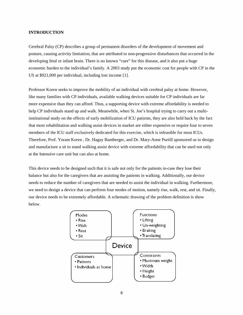
INTRODUCTION Cerebral Palsy (CP) describes a group of permanent disorders of the development of movement and posture, causing activity limitation, that are attributed to non-progressive disturbances that occurred in the developing fetal or infant brain. There is no known “cure” for this disease, and it also put a huge economic burden to the individual’s family. A 2003 study put the economic cost for people with CP in the US at $921,000 per individual, including lost income [1]. Professor Koren seeks to improve the mobility of an individual with cerebral palsy at home. However, like many families with CP individuals, available walking devices suitable for CP individuals are far more expensive than they can afford. Thus, a supporting device with extreme affordability is needed to help CP individuals stand up and walk. Meanwhile, when St. Joe’s hospital trying to carry out a multi-institutional study on the effects of early mobilization of ICU patients, they are also held back by the fact that most rehabilitation and walking assist devices in market are either expensive or require four to seven members of the ICU staff exclusively dedicated for this exercise, which is infeasible for most ICUs. Therefore, Prof. Yoram Koren , Dr. Hagay Bamberger, and Dr. Mary-Anne Purtill sponsored us to design and manufacture a sit to stand walking assist device with extreme affordability that can be used not only at the Intensive care unit but can also at home. This device needs to be designed such that it is safe not only for the patients in-case they lose their balance but also for the caregivers that are assisting the patients in walking. Additionally, our device needs to reduce the number of caregivers that are needed to assist the individual in walking. Furthermore, we need to design a device that can perform four modes of motion, namely rise, walk, rest, and sit. Finally, our device needs to be extremely affordable. A schematic drawing of the problem definition is show below.

7
Figure 1. Schematic drawing of problem definition If we are able to design and manufacture this design successfully in the given budget, it would provide our sponsors a chance to help individuals with CP to walk and be able to test the hypothesis that early mobility in ICU patients actually improves the recovery rate. The customer requirements for the two distinct customer groups which include the patients and individuals at home as well as the caregivers are shown in Table 1 below:
Table 1: Customer requirements for two potential groups Caregivers Patients/Home
Safety Sit to stand movement Sit to stand movement Partially un-weight the patient during walking Partially un-weight the patient during walking Affordability Negotiate with doorways Safety Help to achieve greater independence Comfort of use Compatibility of ventilator Help to achieve greater independence Stable Stable Rigid Rigid Light weight Negotiate with doorways Adjustable to the weight of patients Light weight Affordability Compatibility of ventilator Comfort of use Adjustable to the weight of patients
COMPETITIVE PRODUCT EVALUATION This section will detail the current products available in the market that accomplish the tasks involved in our design. These tasks are divided into: lifting, walking support, and un-weighting devices. (Table 2 discusses the advantages and limitations of the current product and also, represents a sample of the current products available categorized by their function).The price, emergency features, weight limit, and lifting mechanism have also been included. Information on the Lifting and Walking Support Devices was taken from www.spinlife.com, a mobility product website, while the remaining product information was taken from the designers/manufacturers website.

8
Table 2 Current products in the Market: Lifting, Walking Assistance, and Un-weighting Lifting Device
Function Product Price Emergency Features Weight Limit Lifting
Mechanism
Lay to Sit Lift
Invacare Hydraulic
Patient Lift $479 No 450 lbs Hydraulic
Hoyer Advance-H Patient Lift
$1,409 No 340 lbs Hydraulic
Drive Medical Electric Patient
Lift $1,329 Lowering
Mechanism 450 lbs Electrical Actuator
Hoyer Stature $5,322 Lowering Mechanism 500 lbs Electrical
Actuator
Sit to Stand Lift
Invacare Get-U-Up
Hydraulic $910 No 350 lbs Hydraulic
Hoyer Elevate $5,037 Lowering Mechanism 440 lbs Electrical
Actuator
Walking Support
Drive Medical Go-Lite $79 Handbrakes 300 lbs Not Applicable
Nova Cruiser $145 Weight
Activated Brakes
225 lbs Not Applicable
Rifton Pacer Gait Trainers $536-$1890
casters with swivel lock,
brake Not Applicable
Un-weighting SpinoFLEX PMD200[2] Not Available No
400 lb patient with 250 lbs un-weighting
Electrical Actuator
Biodex Unweighting
System[3] Not Available No
500 lb patient with 180 lbs un-weighting
Mechanical
Sit to Stand and Un-
weighting
Up n' Go[4] $2,650 No 250 lbs Pneumatic Spring
KineAssist[5] $250,000
Provides multiple
stabilization features
Not Available Algorithmic Controlled Actuators
Lifting devices fall into two categories: lifting from a lying to sitting position and lifting from a sitting to standing position. Lifting from a lying to sitting position is not a requirement of our design, but has been included to gain a broader background on lifting techniques and better understand the task as performed in a hospital; which will precede the use of our device in that setting. Figure 2 below displays the Hoyer

9
Advance-H Patient Lift that lifts from a lying to sitting position and the Hoyer Elevate that lifts from a sitting to standing position.
Figure 2. Lying to Sitting Lift (left) and Sitting to Standing Lift (right)
Both devices have the ability to be used in a hospital setting and a home setting. A disadvantage of the lifting devices is the incapacity of the lifted user. The user has no control over their movements and is not able to actively participate in their movement. This can be both mentally discouraging and provides no physical activity, which aids in recovery from surgery and general health. Another limitation of the current lifting products is the cost, which is directly related to the lifting mechanism utilized. The hydraulic systems are typically less expensive than the electrical actuator systems. The advantage of the electrical actuator system is that an emergency lowering mechanism accompanies the device in the case of electrical failure. This is a safety feature not available in the less expensive hydraulic units. The manufacturer also influences the cost of the product; Hoyer products are more expensive than competitor products. This is a result of the reputation and quality built into Hoyer products, who was the originator of patient lifts.
Walking Support Devices Walking support devices provide support by allowing weight to be transferred through the hands onto the device, which allows for increased stability and less weight support from the legs. These devices come with various wheel configurations depending on the degrees of freedom desired. Some products have a two wheel and two peg configuration that limits the mobility of the user. Other products have a four-wheel configuration, with either two one-axis fixed wheels and two swivel wheels or four swivel wheels. The products with four swivel wheels allow for greater maneuverability and zero-point turning. Figure 3 below displays the Drive Medical Go-Lite walking support device with handbrakes.

10
Figure 3. Walking Support Device with Handbrakes
Walking support devices can be used in the home and hospital setting. These products are easily obtainable and available to order on the internet at relatively low costs. The current products on the market do not fulfill our customer requirements of sit to stand assistance and un-weighting. Another limitation of the device is the absence of an emergency braking system that allows for the user to remain supported if they lose balance. The current products provide us with a good way of translating motion of the device and allowing for various levels of maneuverability but do not accomplish all of our functions.
Un-weighting Devices Un-weighting devices provide assistance when walking by partially supporting the user’s body weight and providing stability. The general concept involves a rectangular frame that supports a harness hanging from the upper support above the users head. These products are used in the rehabilitation of patients and are developed by specialized companies. Prices were not available from the manufacturers without inquiry, which we chose not to pursue. Figure 4 below displays the Biodex Unweighting System, which is similar in design to the SpinoFlex PMD200.
Figure 4. Un-weighting Device An advantage of the un-weighting devices in the market is the ability of the device to also provide a lifting force from the sitting to standing position. Limitations include the size of the device, because of its

11
height the device is limited to use in a hospital, rehabilitation clinic, and physical therapy office. Home use is not possible because of its width and height and the interference with doorways in the home.
Sit to Stand and Un-weighting Devices Specialty products that accomplish the task of sitting to standing, walking support, and un-weighting are available. The Up n’ Go incorporates lever arms that rotate upwards to assist the patient in standing and a harness system with variable un-weighting settings to provide walking assistance. The basic idea of a walking support device is utilized for translational motion and incorporates four lockable swivel wheels. The KineAssist is a walking and balance retraining tool used for rehabilitation and physical therapy. The device utilizes sophisticated actuator configurations and algorithms to respond to users actions are provide support and stability. Figure 5 below displays the Up n’ Go and the KineAssist devices.
Figure 5. Up n’ Go (left) and KineAssist (right) The Up n’ Go can be used at home and in the hospital setting. It accomplishes the sit to stand, un-weighting, and walking support functions, but lacks in safety. The main limitation of the device is its safety, a requirement of utmost importance in our design. The device does not utilize an emergency braking system, only four independently applied brakes at the wheel. The amount of lifting force is severly limited by the pnuematic cylinders utilized. The stability of the device is also limited. The level arm sit to stand mechanism has no locking mechanism to protect against fallback or fallover. The support only at the waist provides no support of the upperbody, where almost half of a users weight is located. Another limitation of the device is the cost, at $2,650, it is a high expense for use in the home. The KineAssist can not be utilized in the home and only in select hospitals ahd rehabilition clinics with the capital to invest in such a high priced product. The cost of the KineAssist is its greatest limiting factor. The advantages of the KineAssist lies in its safety. Not only does the device provide variable sit to stand

12
assistance and un-weighting, but aids in balancing of the user. The sophisticated algorithm and actuators quickly adjust to keep a patient from falling over and in the case that they do, assists in standing back up. The device can be programed to provide different levels of assistance to the user and provide various combinations of functions.
BACKGROUND RESEARCH This section will detail background research and information gained that provided a greater understanding of the topics involved in the functions of the Sit to Stand Walking Assist Device. The following discussion is divided into multiple sections, including: Patents and Designs, Interviews, and Literature Research.
Patents and Designs In order to complete a survey of all the current designs which accomplish the tasks of sit to stand, walking assist, and un-weighting we performed a patent search. There are a number of devices being developed by design teams and patents being granted for such devices. Some include the Honda Walking Assist Device with Bodyweight Support System [6], the Passive Gravity-Balanced Assistive Device for Sit-to-Stand Task system [7], and Patent No. 5,502,851 [8], which is an assisted lifting, stand and walking device. The Honda Walking Assist Device with Bodyweight Support System is an innovative design that reduces the load on leg muscles and joints by partial support of the user’s bodyweight. A saddle is fixated on a linkage system that mimics the shape and movement of human legs. The user’s feet are placed in the devices shoes that allow the device to move with the user. Two internal motors and a computer control the mount of assistive force provided depending on the motion of the user. The saddle directs the force towards the user’s center of gravity allowing for stability. The device can be seen below in Figure 6.

13
Figure 6. Honda Walking Assist Device with Bodyweight Support System Patent No. 5,502,851 is an assisting lifting, standing and walking device that utilizes linkage system powered by a hydraulic jack to lift a user. The user is attached with a harness that attaches to the legs, mid-section, and around the shoulders. The shoulder straps of the harness are then connected to two arms on each side of the user that rotate to lift the user. The device was designed to lift severely disabled patients from a sitting to standing position and aid in walking. The device provides great stability and can un-weight the user. The Passive Gravity-Balanced Assistive Device for Sit-to-Stand Task system was developed at the University of Delaware and utilizes a spring-loaded linkage system and counter weight to assist in standing. The linkage system is strapped to the user’s legs and mid-section and guides them from a sitting to standing position. The spring contracts while a counter weight descends providing a lifting force to the user. The device can be seen below in Figure 7.
Figure 7. Passive Gravity-Balanced Assistive Device for Sit-to-Stand Task
Interviews We had the opportunity to meet with the staff in the Intensive Care Unit at St. Joe’s Hospital in Ann Arbor, MI. They were able to demonstrate the current products they utilize with patients. In each room they had overhead Hoyer lifts that are capable of lifting a 500 lb patient from a lying position to a sitting position with a full body sling. They also demonstrated a sit to stand lift similar to the Hoyer Elevate lift discussed in previously. The downfalls of this device were described, including: its uncomfortable sling design, large forces created on patient’s torso, and limited width. The large forces created on the patients torso was a large concern because of the pressure applied to the rib cage. Specific surgeries, like an open-heart procedure, leave the sternum broke and in the healing process. Large forces can collapse the rib cage and severely hurt a patient. The first hand experience in the environment where our device will be utilized provided us with great insight into a successful product.

14
Literature Research Additional journal articles and textbooks were referenced in order to further understand the dynamics involved in the sitting to standing task and the define dimensions of the human body. We researched the area of anthropometry to better understand the lengths of various limbs and the statistical variance in population. An Introduction to Human Factors Engineering [9] and Occupational Biomechanics [10] were used to assign engineering specifications that defined the dimensions of our design. Characteristics of the movement we researched included: the sit to stand time, walking velocity, and body trajectory when standing. The sit to stand time [11], walking velocity [12], and body trajectory from sitting to standing [11] were all found in journal articles and used to define our engineering specifications as presented previously
ENGINEERING SPECIFICATIONS According to project requirements, detailed quantitative engineering specifications were determined. Corresponding target values were obtained either by discussing with sponsors or searching through literatures. This section summarizes the engineer specifications and approaches used to set engineering targets.
The engineering specifications developed from the customer requirements were grouped together based on the subsystems of the device. Values of engineer specifications for both ICU and home uses are listed in Table 3 below:
Table 3: Engineer specifications and corresponding targets
Engineer specifications Targets
ICU HOME
Lifting Mechanism Lift force [lbf] 247 135 Un-weighting force [lbf] 90 45
Harness Number of hooks [#] ≥4 ≥4 Area of contact of harness [in2] ≥388 ≥388 Harness pressure[psi] 0.64 0.64 Buttocks Width [in] 13-16 13-16 Shoulder Width [in] 14-19 14-19
Braking Systems

15
Number of brakes [#] ≥2 ≥2 Time for emergency stop [sec] ≤0.25 ≤0.25 Distance moves before stop [in] 2 2
Device Characteristics Weight of the device [lbm] 55 55 Width of the device [in] 16-48 16-32 Height of the device [in] ≤80 ≤80 Cost [$] ≤2000 200
Assistant Number of person required to assist [#] <3 1 Number of handgrips [#] ≥2 ≥2 Length of hand grips [in] 2.8-3.5 2.8-3.5 Diameter of hand grips [in] 1.6-2.4 1.6-2.4
Functions Rise
Time to stand up [sec] 3 3 Starting height [in] 22-30 22-30 Stopping height [in] 38-46 38-46 Horizontal travel distance [in] 17-21 17-21 COM of device and user [in] 25 25 Assistance when standing (Yes/No) Yes Yes
Walk
Walking velocity [in/sec] 16 16 COM of device and user [in] 36 36 Lifting system engaged (Yes/No) No No Un-weighting system engaged (Yes/No) Yes Yes
Rest
Walking velocity [in/sec] 0 0 COM of device and user [in] 36 36 Assistance when standing (Yes/No) Yes Yes Lifting system engaged (Yes/No) No No Un-weighting system engaged (Yes/No) Yes Yes
Sit
Time to sit [sec] ≥3 ≥3 Starting height [in] 38-46 38-46

16
Stopping height [in] 22-30 22-30 Horizontal travel distance [in] 17-21 17-21 COM of device and user [in] 25 25 Assistance when sitting (Yes/No) Yes Yes
Some of the most important engineering specifications for each subsystem are highlighted below: Lifting mechanism: The maximum lift force to lift patients up was determined to be 247 lbf and the un-weighting force to be 90 lbf. The lift force was set to be the full body weight (250 lbm) of the patient and the un-weight force was about 35% of a patient’s weight. However, the actual required lifting force will be precisely evaluated according to the final design. Harness: A minimum of four hooks were determined for harness design. This sets more constraints on the patient’s upper body movement and prevents users from falling over. Buttock width and shoulder width of the harness were determined according to engineering anthropometry and workspace design [9]. The range was determined from 5th percentile to 95th percentile based on 50/50 male/female population. Braking systems: Time for emergency stop was determined to be 0.25 seconds. This is the average response time of a fully capable individual [13]. Device characteristics: The minimum width and height of the device were determined to be the 50th percentile of anthropometric data [9] of stature and the upper bound were determined according to the normal height and width of home used doors [14]. Assistant: Length and diameter of handgrip were determined based on the anthropometric data of hand breadth [5] and hand length [5]. The range was determined from 5th percentile to 95 percentile based on 50/50 male/female population. Functions: Time to rise was determined according to a study of Sit-to-stand movement pattern [11]. Walking speed was determined based on a study of walking speed of elderly patients [12]. Starting height, ending height and horizontal travel distance of users were determined based on the anthropometric data of popliteal height plus elbow rest height [9], elbow height [10] and leg length. The range was determined from 5th percentile to 95 percentile based on 50/50 male/female population. Depending on the level of relevance, every engineering specification was assigned a number with 9 meaning strongly related, 3 meaning somewhat related, 1 meaning weakly related and blank meaning totally unrelated. The weighted score of each engineer specification was then calculated by summing the

17
values of weight of each customer requirements times the relevance score. A detailed quality function deployment (QFD) can be found in Appendix A.
CONCEPT GENERATION This section details the processes used to generate design concepts for the design problem. The four modes of the device: rise, walk, rest, and sit were used to define a functional decomposition. Further brainstorming was accomplished by developing two diagrams with our device as the central idea: 1) a taxonomy to understand the possible solutions to achieve the functions of the device, and 2) the interactions the device has with the environment. With the increased understanding of the functions and interactions our device has with the environment we were able to develop concepts for each subsystem. The concept generation was done considering the hospital and home user, no differentiation was considered.
Functional Decomposition In order to begin the concept generation process, it was important to have a full understanding of the energy and actions involved with each mode of our device. Between each mode change, a user has to input a signal in order to engage the mechanism necessary to fulfill the requirements of the new mode. The user input can come from either the patient or the assistant. The first function needs to engage the braking system, to allow for stability while rising. The rising motion requires the release of stored energy that is then applied to the patient through some mechanism. A mode switch is then required by a user input in order to allow for the lifting mechanism to either become disengaged or allow for the addition of the un-weighting system and to disengage the braking mechanism. The reverse process is needed in order to allow a patient to go from a standing to sitting position. While in motion the braking system needs to be able to engage in case of emergency by either the patient or assistant. This involves a release of stored energy that is then transferred to the ground to stop the walking motion. A detailed functional decomposition can be found in Appendix B.
Brainstorming In order to fully understand the functions and the constraints of the device we developed taxonomy and an interactions diagram. The taxonomy starts with the device at the center with the various functions, or subsystems, branching out to the second level. The third level of the taxonomy defines different ways of fulfilling each function. The detailed taxonomy can be found in Appendix C. The interaction tree was used to define the modes of interaction between the device, patient, caregiver, and environment. Physical interactions take place between the patient, device, environment, and caregiver. Verbal communication
18
takes place between the patient and caregiver. There is then a physical input from the caregiver to the device and following an energy transfer from the device to the patient. The detailed interaction diagram can be found in Appendix D and all brainstorm concepts are documented in Appendix E
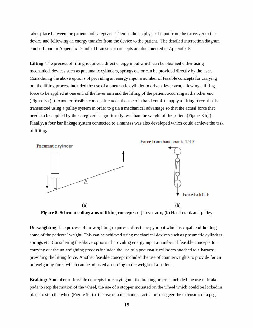
Lifting: The process of lifting requires a direct energy input which can be obtained either using mechanical devices such as pneumatic cylinders, springs etc or can be provided directly by the user. Considering the above options of providing an energy input a number of feasible concepts for carrying out the lifting process included the use of a pneumatic cylinder to drive a lever arm, allowing a lifting force to be applied at one end of the lever arm and the lifting of the patient occurring at the other end (Figure 8 a). ). Another feasible concept included the use of a hand crank to apply a lifting force that is transmitted using a pulley system in order to gain a mechanical advantage so that the actual force that needs to be applied by the caregiver is significantly less than the weight of the patient (Figure 8 b).) . Finally, a four bar linkage system connected to a harness was also developed which could achieve the task of lifting.
(a) (b) Figure 8. Schematic diagrams of lifting concepts: (a) Lever arm; (b) Hand crank and pulley
Un-weighting: The process of un-weighting requires a direct energy input which is capable of holding some of the patients’ weight. This can be achieved using mechanical devices such as pneumatic cylinders, springs etc .Considering the above options of providing energy input a number of feasible concepts for carrying out the un-weighting process included the use of a pneumatic cylinders attached to a harness providing the lifting force. Another feasible concept included the use of counterweights to provide for an un-weighting force which can be adjusted according to the weight of a patient. Braking: A number of feasible concepts for carrying out the braking process included the use of brake pads to stop the motion of the wheel, the use of a stopper mounted on the wheel which could be locked in place to stop the wheel(Figure 9 a).), the use of a mechanical actuator to trigger the extension of a peg

19
such that the wheel is lifted from the ground causing the wheel to stop(Figure 9 b).) and the use of a mechanical actuator used to retract the wheel such that the peg comes in contact with the floor causing it to stop (Figure 9 c)).
Figure 9. Schematic drawing of lifting concepts: (a) stopper on a wheel; (b) extended peg; (c) retract wheel
Translating (movement of a patient): A number of feasible concepts for carrying out the translating process included the use two-wheel/two-peg frame and a four-wheel frame. The two-wheel/two-peg frame provides a greater stability to the system because of the pegs which do not roll and hence provide extra stability in the stationary state. The four-wheel frame allows the patient to move around with a greater ease and also allows a greater range of motion that can be attained.

20
CONCEPT SELECTION PROCESS This section discusses the method used to select concepts for “Alpha Designs”. A concept selection table was created and advantages and disadvantages for each concept were listed for further development of final design.
Concept Selection Table Selection tables for each concept were generated to better differentiate among competing concepts. Several criteria were determined and weighted according to its level of importance. Setting the first concept as a baseline, the rest were compared with it. Concepts were rated based on the relative performance with 3 meaning the same and 4 or 5 meaning better performance. Then concepts were ranked based on the total score for each function. The most feasible concepts of each function have been demonstrated in Table 4 below. Detailed concept selection tables have been attached in Appendix F.
Table 4 Feasible concepts for each function Lifting Un-weighting Braking Translating
1 4-bar Linkages Pneumatics Stopper on wheel 4 wheels 2 Gear Spring Brake pads 2 pegs/2 wheels 3 Pulley/Hand crank Counterweight Extended peg 4 Lever arm Retract wheel
Concept Comparison Table Based on selection tables, advantages and disadvantages of the most feasible concepts were discussed. Table 5 listed the results.
Table 5 Advantage and disadvantage for each concept Lifting system
Concept Advantage Disadvantage
4-bar Linkages
1.Follow the trajectory of body 1.Difficult to model 2.Variable power along trajectory 2.Difficult to repair 3.Easy to manufacture 4.Stable 5.Rigid
Gear 1.High mechanical advantage 1.Difficult to assemble 2.Rigid 2.Can cause entanglement
of harness
Pulley/Hand crank
1.High mechanical advantage 2.Durable 3.Easy to manufacture
1. Can cause entanglement of harness 2.Big device size
3.Unstable for patient
Lever arm 1.Rigid 2.Easy to manufacture
1.Contain sharp edges 2.Big device size
Un-weighting system

21
Concept Advantage Disadvantage
Spring/Pneumatic 1.Easy to implement 2.Robust
1.Hard to engage in the system
Counter weight 1.Adjustable of force 1.Extra burden to patients 2.Robust 2.Proper constraint needed
Braking system Concept Advantage Disadvantage
Stopper on wheel
1. Stopping time is very small 2.Very durability 3. Size of the mechanism is extremely small.
1. Difficult to manufacture 2. Causes instability of system.
Brake pad 1.Fully developed concept 2. Readily available in the market
1. Requires repeated replacement of brake pads. 2. Response time is slow.
Extended peg
1.Stopping time is very small 2.provides additional stability after the pegs are extended
1. Causes instability of system 2. Could cause device to topple.
Retract wheel
1. Stopping time is very small 2. Provides additional stability after wheels are retracted.
1. Causes instability of system 2. Could cause device to topple
Moving mechanism Concept Advantage Disadvantage
2 wheels/ 2 pegs
1. Provides stability to the system. 2. Easier to hold the device still when going from sit to stand or vice versa
1. Difficult to move around 2. Limits maneuverability
4 wheels
1.Easy to move 2.Provides a high degree of maneuverability
1. Difficult to hold the device still when going from sit to stand or vice versa.
2.Unstable
Concept Description This section will describe an overview of our design. The design has been sectioned into subsystems including: the frame, four-bar mechanism, and pneumatics. Each subsystem will be described and then the operation of our design will be presented. Frame: The frame of our device has been designed to provide stability of the device and user while going from a sitting to standing position and while mobilizing. The frame will be built from t-slot extruded aluminum framing that is cut to length. The framing will be fastened together using water-jet cut aluminum plates along with specialized fasteners designed for the t-slot framing. An example of a cross

22
section of 1.5 inch t-slot extruded aluminum framing and the fastening method can be seen below in Figure 10. Note that the plate displayed is not an actual part of our model; detailed construction and assembly plans will be outlined to later sections.
Figure 10. Right: Cross-section of t-slot extruded aluminum framing. Left: Aluminum plate and t-slot bolt fastening technique.
The frame has been designed with each side being symmetric to the opposite side. Each side of the frame will be exactly the same, but be designed off-handed so that the outside appearance of the device appears consistent. 45° frame members have been added to the sides of the frame to create a more rigid structure. The side frame design can be seen below in Figure 11 on the left hand side. Two cross members will be connected across the front of the device to each side of the frame to. In order to avoid a hinge-like affect at the corner joints, 45° corner supports have been attached from the cross members to each side of the frame. Corner supports appear on the top and bottom cross beams. The entire frame can be seen below in Figure 11 on the right hand side. Finally, it should be noted that 4 swivel caster wheels with brakes have been attached to the corners of the bottom of the frame for mobility.
Figure 11. Left: Side of frame. Right: Entire frame.
Slot for t-nut
Bolts
T-nuts Aluminum plate

23
Four-bar Mechanism: The four-bar mechanism has been designed using the same t-slot extruded aluminum framing as the frame. The four-bar mechanism has been designed to follow the trajectory of a human standing and will be further discussed in the operation of our design in following sections. A side view of the A arm, B arm, and coupler along with the grounds of the four-bar mechanism and lifting point can be seen on the left-hand side in Figure 12 below. The two four-bar mechanisms that will appear in our device will be identical and synchronized by a cross beam at the uppermost point of the four-bar mechanism when it is in the sitting position, this can be found on the right hand side in Figure 12 below.
Figure 12. Left: Side view of four-bar mechanism. Right: Synchronized set of four-bar mechanisms. The joints of the four-bar mechanism have been carefully designed to provide free rotation with minimal friction throughout the full rotation of the linkage arms. Each linkage arm has been fastened to water-jet cut aluminum plates with holes cut for a steel shaft or ball bearing with a steel shaft depending on the specific arm. The B arm to frame joint can be seen in Figure 13 below with an exploded view on the left and the built configuration on the right.
Figure 13. Frame to B arm joint. Left: Exploded view. Right: Built configuration.

24
The left member is a vertical beam from the frame, which is fastened to aluminum plates with through holes at the top that the steel shaft can sit in. The B arm, which appears on the right side has a through hole cut, along with aluminum plates fastened to it where steel ball bearings rest. The steel shaft connects the B arm to the vertical frame member and is constrained by shaft collars on the outside ends of the shaft. It should be noted that washers appear between the plates on the vertical frame member and the plates on the B arm and are signified by a short tube in the figure above. The remaining three joints all have the same configuration, the B arm to coupler, the coupler to A arm, and A arm to frame. The two arms at each joint all lie in the same plane. Each has aluminum plates fastened to the linkage member with holes on one member for the shaft, while there are holes on the other for steel ball bearings. A steel shaft connects the two members and is held in place by shaft collars placed in the middle of two aluminum plates. The joint configuration can be seen in Figure 14 below with an exploded view on the left and the built configuration on the right.
Figure 14. B arm to coupler, coupler to A arm, and A arm to frame joint. Left: Exploded view. Right: Built configuration.
Pneumatics: The pneumatic system will perform the lifting of the four-bar mechanism and will be the powerhouse of our design. Two pneumatic cylinders are placed in the device, one on each side of the frame, in the same plane as the two four-bar mechanisms. The piston end of the cylinder is mounted to the A arm near the A arm to coupler joints, while the shell end of the cylinder is mounted to the bottom cross member of the frame and a vertical beam on the front of the frame. The pneumatics selected are double-acting, but only one direction action will be utilized. The other chamber in the cylinder will be open to the atmosphere and will not provide any forces. Tubing will connect the two sides together at a t-split connection that will lead tubing to a valve connecting to a bike pump. The bike pump will pressurize the system and extend the piston to rotate the A arm. The configuration of the pneumatic system can be seen below in Figure 15.

25
Figure 15. Placement of pneumatic cylinders Placement of the pneumatic cylinders below the four-bar mechanism can be seen in Figure 16 below. A side view appears on the left, and a three dimensional view showing the cross member connecting the two four-bar mechanisms and two pneumatic cylinders appears on the right. The two four-bar mechanisms are synchronized by the cross member at the end of the B arm and the force supplied by two identical pneumatic cylinders acting on the A arm.
Figure 16. Placement of pneumatic cylinders.

26
Harness: In order to transfer the lifting forces of the four-bar mechanism to the user a tree climbing harness will be utilized. The harness has shoulder straps that are connected around the waist and around the legs. Climbing hooks will be attaches from the should straps to the lifting loop hole points previously shown on the coupler linkage arm. The climbing harness utilized in the design can be found in Figure 17 below.
Figure 17. Tree climbing lifting harness.
Operation of device: Now that all the components and subsystems have been presented it is possible to present the entire design and it’s operation. As the pneumatic system is pressurized using the bike pump, the piston of the pneumatic cylinder travels upwards and lifts the A arm of the linkage system. The sitting position and standing position orientation of the pneumatic cylinder can be seen below in Figure 18.
Figure 18. Sitting and Standing orientation of pneumatic cylinder. As the piston of the pneumatic cylinder travels upwards it pushes against the A arm of the linkage system and in turn the coupler and B arm rotate around the ground points and their joints. The lifting point on the coupler travels through the natural trajectory of a human from the sitting to standing position. This point transfers the lifting force to the user through the harness and lifts the person upwards to the standing position. The rotation of the linkage arms can be seen in Figure 19 below. The natural trajectory of the

27
human has been outlined in red and can be seen to follow the trajectory of the lifting point on the coupler throughout the rotation of the linkage arms.
Figure 19. Rotation of linkage arms with natural human standing trajectory outlines in red. Finally, the operation of the entire device can be seen in Figure 20 below.
Figure 20. Operation of device.

28
PARAMETER ANALYSIS This section describes the approaches used to determine the specific parameters for our final design. Analysis from both ergonomic and mechanical points of view was conducted to support the decisions.
Path and Geometry of the Linkages The path of the linkages was determined to be the trajectory of individual’s shoulder when standing up. It’s believed that over shoulder trajectory would create more constraints on users than that from the waist and would better serve the purpose of preventing users from falling over. Other constraints also include frame not interfering with bed/chair, linkages not interfering with each other and pneumatics cylinder easy to implement. Comparing all the concepts generated in Lincages software, the final geometry of the linkage design, shown in Figure 21 below, was determined to be 16 inches for the input arm, 9.75 inches for the follower arm and 34.5 inches for the coupler arm. See all the linkage design concepts in Appendix G.
Figure21: Linkage selection of final design

29
Pneumatic Selection Pneumatic was selected to be 6498K679 on McMaster-Carr. Its basic dimensions were listed in Table 6 below. The pneumatic was selected such that the distance between the input arm and the frame initially is greater than pneumatic initial length so that pneumatic can fit and that the extended length, which equals final length minus initial length, is less than the stroke length so that pneumatic is ample to use. Schematic drawings for linkages’ initial position and final position are shown in Figure 22 below. Rod clevis and pivot bracket were also selected to be 6498K44, 6498K73 and 6498K564 to mount pneumatic on linkages. Detailed specification sheets are documented in Appendix H
Table 6 Basic dimensions of selected pneumatic cylinder Parameters Dimension Outer Diameter [in] 1.56 Initial Length [in] 15.51 Stroke Length [in] 10 Force [lbf] 162
(a) (b)
Figure 22.Schematic drawings for linkages: a) initial position; b) final position

30
Dimensions of the Frame Several dimensions of the frame were determined by the anthropometric data of 50th percentile based on 50/50 male/female population. Manufacturability was also an important factor when designing the basic shape of the frame. Base height: The base height marked as A in Figure 23 was determined to 34.78 inches. This is the sitting elbow rest height [9] where patients can rest their arms when sitting. And it is the most comfort height for standing up when reaching out arms. Total height: The total height (B) was determined to be 61.56 inches. This height needs to be higher than shoulder height of the individuals [9] since the 4-bar linkages will follow the trajectory of the individual’s shoulder. At the same time, it’s also limited by the constraints such as weight of the device, cost and height of the doorways. The height chosen is the minimal height that satisfies all the limitations.
Figure 23. Schematic drawing of frame design
Width: The width of the device was determined to be 36 inches. This was designed to give users more space while in the device and at the same time make a compromise with the size of the doorways.
B
A

31
Beam Analysis This section presents simple beam analysis for our device, which was used to determine the important geometry parameters of the device including linkage thickness, coupler cross-beam thickness, and frame thickness. It should be noted here that a safety factor of two was used for the analysis. Linkage thickness: The linkage thickness was determined to be 1.5 in. This thickness is an important parameter because there are huge forces from pneumatic cylinder and patient’s weight, thus creating a significance bending on the coupler and could causing serious safety problems to the user. To determine this value, a stress analysis was performed based on the worst case scenario. The maximum bending stress within the linkage bar was then calculated using Equation 2 below
𝜎𝜎𝑚𝑚𝑚𝑚𝑚𝑚 = 𝑀𝑀𝑚𝑚𝑚𝑚𝑚𝑚 𝑦𝑦𝐼𝐼
=(𝐹𝐹𝑝𝑝𝑝𝑝 ∙𝐿𝐿1+1
2𝑊𝑊∙𝐿𝐿2)∙12𝑡𝑡1
12𝑡𝑡4 =𝜎𝜎𝑌𝑌
2 (Eq.2)
where, 𝐹𝐹𝑝𝑝𝑝𝑝 is the maximum force from pneumatic cylinder (162 lbs), W is the maximum target weight of
the patient (250 lbs), L1 is the distance from pneumatic pivot point to the coupler (2.75 in), L2 is the distance between the hanging position of the patient’ shoulder to the coupler (6.25 in), 𝜎𝜎𝑌𝑌 is the yield strength of the material (3∙104 psi), and t is the thickness to be determined. Several simplifications made are:
1) All the linkage bars are of the same thickness. 2) Only the pneumatic force and weight of the patient creates bending moments to the coupler. 3) Linkages’ weights are neglected compared to pneumatic cylinder forces 4) The cross section of the beam was assumed to be square with thickness d to simplify the complex
extruded aluminum cross section. The detailed calculation is provided in Appendix I. Coupler cross-beam diameter: The coupler cross-bar, shown in Figure 21 on page 28, thickness was determined to be 1.5 inches. This cross-bar plays an important role in synchronizing the two half linkages. But at the same time, this bar undertakes a bending moment due to the different forces (disturbances) at each side of the pneumatic cylinder. The maximum stress within the cross-bar was calculated using Equation 3
𝜎𝜎𝑚𝑚𝑚𝑚𝑚𝑚 = 𝑀𝑀𝑚𝑚𝑚𝑚𝑚𝑚 𝑦𝑦𝐼𝐼
=𝐹𝐹𝑝𝑝𝑝𝑝𝑝𝑝𝑝𝑝𝑚𝑚𝑚𝑚𝑡𝑡𝑝𝑝𝑝𝑝 ∙𝐿𝐿∙12𝑡𝑡
112𝑡𝑡
4 = 𝜎𝜎𝑌𝑌2
(Eq.3)

32
where, 𝐹𝐹𝑝𝑝𝑝𝑝𝑝𝑝𝑝𝑝𝑚𝑚𝑚𝑚𝑡𝑡𝑝𝑝𝑝𝑝 is the maximum force of pneumatic cylinder (162 lbs), 𝐿𝐿 is the length of the cross
beam (25 in), 𝜎𝜎𝑌𝑌 is the yield strength of the material (3∙104 psi), and t is the thickness to be determined. Several simplifications made are:
1) The worst scenario was assumed that there is only one pneumatic cylinder on one side (“perfectly unsymmetrical”).
2) The cross section of the beam was assumed to be square with thickness t to simplify the complex extruded aluminum cross section.
The detailed calculation is provided in Appendix I. Frame beam thickness: The base of the frame was designed to be built by 1.5 in thick extruded aluminums. The purpose to choose 1.5 in instead of 1 in was to give more support to the huge pneumatic cylinder force. The stress analysis for the base cross-beam was calculated using Equation 4
𝜎𝜎𝑚𝑚𝑚𝑚𝑚𝑚 = 𝑀𝑀𝑚𝑚𝑚𝑚𝑚𝑚 𝑦𝑦𝐼𝐼
=𝐹𝐹𝑝𝑝𝑝𝑝𝑝𝑝𝑝𝑝𝑚𝑚𝑚𝑚𝑡𝑡𝑝𝑝𝑝𝑝 ∙𝐿𝐿∙12𝑡𝑡
112𝑡𝑡
4 = 𝜎𝜎𝑌𝑌2
(Eq.4)
where, 𝐹𝐹𝑝𝑝𝑝𝑝𝑝𝑝𝑝𝑝𝑚𝑚𝑚𝑚𝑡𝑡𝑝𝑝𝑝𝑝 is the maximum force of pneumatic cylinder (162 lbs), 𝐿𝐿 is the length of the cross
beam (36 in), 𝜎𝜎𝑌𝑌 is the yield strength of the material (3 ∙104 psi), and t is the thickness to be determined.
The two sides of the frame base were also designed to be 1.5 in thick, which was used to lower the frame’s center of mass and keep the device stable. The vertical long beams were also designed to be 1.5 in thick, because it was made of one piece of aluminum beam and the crack inside this beam will propagate through the entire beam fast to cause fracture. Therefore, without any knowledge of the crack length inside these beams, it would be safer to strengthen it by giving a larger thickness of 1.5 in. Moreover, this size fits well with the base size (1.5 in). Similarly, the vertical beams supporting the pneumatic cylinders were also designed to be 1.5 in thick to better support the huge pneumatic forces. All the other beams were designed to be 1 in thick since they are not major force carriers, and at the same time, this will give a lighter weight of the device.
Fastener Plates A variety of fastener plates were used to join the extruded aluminum beams. The shape of the plates, as well as the holes sizes and locations followed the existing fastener plate’s products from H. H. Barnum Company. See other design analysis for material selection in Appendix J.

33
FINAL DESIGN This section discusses the final design with dimensioned engineering drawings. A part list and part numbers for all major components are documented followed by a detailed description of the operation of our design.
Detailed Drawings Final design of the system consists of four major sub-components: frame, joining plate, four bar linkage and pneumatic.CAD drawings for each sub components as well as part lists are shown in Figure 24 below. It should be noted that not all parts are labeled for clarity and that each part in the following drawings is marked to show its position in what will be the final version of the prototype. Detailed engineering drawings are documented in Appendix K and bill of materials is included in Appendix L.
A)

34
B)
C)

35
D)
E)
Figure 24 Detailed CAD drawings of final design. A) Frame B) Joining plate (front) C) Joining plate (back) D) Four-bar linkages E) Pneumatics

36
Detailed Operation Process Operations needed for assistant to mobilize a user can be categorized into three main phase: standing, walking and sitting, shown in Figure 25 below. This section discusses operations for each phase in detail.
Lifting from sitting to standing position To lift user from sitting to standing position, assistant needs first to wear harness on user and position device in front of user. Then s/he needs to engage four independent brakes to lock device in place. Afer attaching harness to lifting arms, assistant will utilize hand pump to pressurize pneumatic system. Extension of pneumatic cylinder rod will cause four-bar linkage arms to rotate. Harness then transfers lifting force to user, helping user standing up following standing trajectory.
Mobilization (Walking) After user standing up, assistant can disconnect pump from pneumatic system to remain pneumatic system pressurized. Then s/he needs to disengage four independent brakes. User is then able to easily maneuver the device as they walk. Assistant can stabilize device and user using cross bar at back. Pressurized pneumatic system will provide support of body weight as user walks.
Guiding from standing to sitting position To guide user sitting back, assistant needs first engage four independent brakes. Then s/he needs to control valve to slowly release pressure from pneumatic system. Body weight of user will pull down on four-bar linkage arms and as pressure decreases user is guided to sitting position by four-bar linkage arms. Lastly, assistance will detach harness from lifting arms and take it off from user.
Figure 25 Schematic drawing of detailed operation process

37
FABRICATION PLAN This section provides detailed manufacturing plan for parts need to be produced and assembly plans for putting together prototype. Diagrams and simple step-by-step instructions are provided so that design can be reproduced by anyone.
Manufacturing Plan Major parts need to be manufactured are frame, four-bar linkages and joining plate. Other manufacturing process includes cut shaft to length. This section documented manufacturing process for all the major components in detail.
Frame/Four-bar linkages The frame will be manufactured from 1.5 inch and 1 inch 6063 extruded aluminum members purchased from Tslot Company. The various members of extruded aluminum would be cut to length and then put together using bolts and t-nuts. Four-bar linkages would be made of 1.5 inch extruded Aluminum members and would be mounted to frame using ball bearings, shafts and shaft collars which will be purchased from McMaster-CARR.
Joining plates The mounting plates are made of 0.25 inch and 0.5 inch thick 6061 Aluminum plate that will be purchased from McMaster-CARR. Joining plates would be manufactured using a water-jet in the Engineering Research center. Water-jet cutting was determined to be the most appropriate technique for manufacturing the mounting plates because of the number if plates that need to be manufactured and the detail that is needed for each of these plates. Moreover, the plates are thin, water-jet cutting proves to be the ideal process. Engineering drawings for all components can be found in Appendix K and CAD drawings for water-jet cut plates can be found in Appendix M. Table 7 below summarizes manufacturing method of major components used for prototype:
Table 7. Manufacturing process table Frame Part name
Qty
Operation Tool Note
F1 2 Cut to length Band saw 300rpm&File end F2 2 Cut to profile and mill to length Band saw/Mill 1200rpm mill &File end F3 2 Cut to length and 45 degree plane Band saw 300rpm&File end F4 2 Cut to length and 45 degree plane Band saw 300rpm&File end F5 2 Cut to profile and mill to length Band saw/Mill 1200rpm mill &File end

38
F6 2 Cut to length Band saw 300rpm&File end F7 2 Cut to length and 45 degree plane Band saw 300rpm&File end F8 1 Cut to length Band saw 300rpm&File end F9 1 Cut to length Band saw 300rpm&File end F10 2 Cut to length and 45 degree plane Band saw 300rpm&File end F11 2 Cut to length and 45 degree plane Band saw 300rpm&File end F12 2 Cut to profile and mill to length Band saw/Mill 1200rpm mill &File end Linkages Part name
Qty Operation Tool Note
L1 2 Cut to length Band saw 300rpm&File end L2 2 Cut to length Band saw 300rpm&File end
L3 2 Cut to length Band saw 300rpm&File end Drill one 1/2 inch hole Mill 1200rpm&1/2 inch end
L4 1 Cut to length Band saw 300rpm&File end Joining plates Part name Qty Operation Tool Note P1 4 Cut to profile Water jet P2&P2s 2 Cut to profile Water jet P3&P3s 2 Cut to profile Water jet P4 2 Cut to profile Water jet P5&P5s 4 Cut to profile Water jet
P6 4 Cut to profile Water jet Ream one 0.5 hole Mill 800rpm& 0.5 reamer
P7&P7s 2 Cut to profile Water jet P8 2 Cut to profile Water jet P9 2 Cut to profile Water jet P10&P10s 2 Cut to profile Water jet P11 4 Cut to profile Water jet P12 4 Cut to profile Water jet
P13 4 Cut to profile Water jet Ream one 0.5 hole Mill 800rpm& 0.5 reamer
P14 2 Cut to profile Water jet P15 2 Cut to profile Water jet P17 2 Cut to profile Water jet PL1&PL1s 12 Cut to profile Water jet PL2 8 Cut to profile Water jet PL3 4 Cut to profile Water jet PL4 4 Cut to profile Water jet 800rpm& 1.126 reamer PL5 2 Cut to profile Water jet

39
Assembly Plan This section describes the detailed assembly procedures for our device. There are four sub-components: frame, four-bar linkages, pneumatics and wheels. The subsections below provide the assembly steps for these two sub-components.
Frame Frame is the major weight bearing component of our design. The frame is made of 1.5 and 1inch extruded aluminum beams that are joined together using mechanical fasteners. Figure 26 below shows the CAD model of the frame.
Figure 26: Frame CAD model
Due to the highly symmetric feature of the frame structure, the strategy used to assemble the frame is to assemble each side of it and then add cross-bars to join the two sides together. It should be mentioned here in advance that the bolts and nuts are not shown in the CAD drawings for clarity. This sub-assembly was put together using the following steps:
40
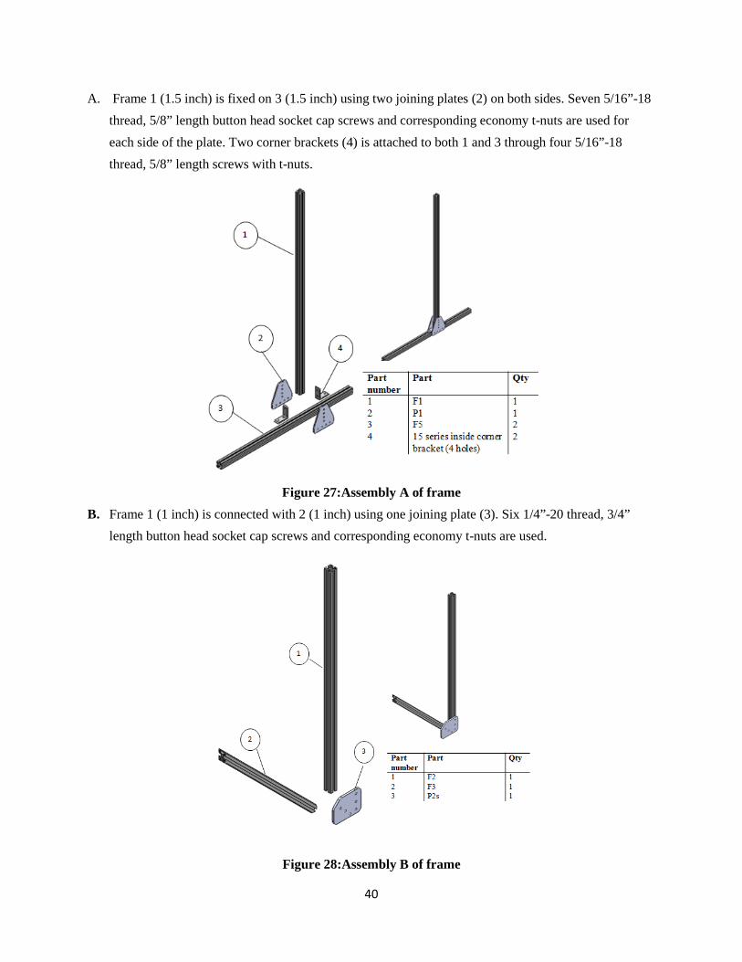
A. Frame 1 (1.5 inch) is fixed on 3 (1.5 inch) using two joining plates (2) on both sides. Seven 5/16”-18 thread, 5/8” length button head socket cap screws and corresponding economy t-nuts are used for each side of the plate. Two corner brackets (4) is attached to both 1 and 3 through four 5/16”-18 thread, 5/8” length screws with t-nuts.
Figure 27:Assembly A of frame
B. Frame 1 (1 inch) is connected with 2 (1 inch) using one joining plate (3). Six 1/4”-20 thread, 3/4” length button head socket cap screws and corresponding economy t-nuts are used.
Figure 28:Assembly B of frame

41
C. Frame 1 (1 inch), 3 (1 inch) and 4 (1 inch) are then connected to assembly B using joining plate 2 and 5. Thirteen 1/4”-20 thread, 1/2” length button head socket cap screws and corresponding economy t-nuts are used.
Figure 29:Assembly C of frame
D. Assembly A and C are then connected through joining plates 1, 2, 4, 5, and 6 and corner brackets 3.Six 1/4”-20 thread, 3/4” length button head socket cap screws and corresponding economy t-nuts are used to connect plate 1 and 2 on both sides together. Four 5/16”-18 thread, 5/8” length screws with t-nuts lock the top part of assembly C on assembly A. Four 1/4”-20 thread, 3/4” length screws with t-nuts connect plate 4 and 5 together and 5 is then fixed on assembly A with three 5/16”-18 thread, 5/8” length screws. Three 5/16”-18 thread, 5/8” length screws connects plate 6 with assembly A locking the bottom of assembly C on A. Two corner brackets (3) are used to fix the middle part of assembly C to A.

42
Figure 30:Assembly E of frame E. Frame 1 (1 inch) is connected to assembly D using joining plate 3 and corner bracket 2. Four 1/4”-20
thread, 1/2” length button head socket cap screws and corresponding economy t-nuts are used. Frame 4 (1.5 inch) is connected to assembly D through joining plates 7 and 8 and corner brackets 5 and 6. Three 1/4”-20 thread, 3/4” length screws with t-nuts are used to connect the vertical holes of plates 7 and 8 and two 5/16”-18 thread, 5/8” length screws with t-nuts are used to attach plate 7 to frame 4.

43
Figure 31:Assembly F of frame
F. Frame 3 (1.5 inch) is connected to assembly E through joining plate 1 and 2 on top and 5 at bottom.
Three 1/4”-20 thread, 3/4” length button head socket cap screws and corresponding economy t-nuts are used to attach plate 2 and 1. Four 5/16”-18 thread, 5/8” length screws with t-nuts are used to lock top of frame 3 with assembly E through plate 2. Seven other 5/16”-18 thread, 5/8” length screws with t-nuts are used to lock the bottom of frame 3 to assembly E. Additionally, eight 5/16”-18 thread, 5/8” length screws with t-nuts are used to fix plates 4 on frame 3.
Figure 32:Assembly F of frame

44
G. Frame 2 (1 inch) is connected to assembly F through joining plates 1. Twelve 1/4”-20 thread, 3/4” length button head socket cap screws and corresponding economy t-nuts are used to lock frame 2 to assembly F. Frame 4 (1.5 inch) is connected to assembly F through joining plates 3. Eight 5/16”-18 thread, 5/8” length screws with t-nuts are used to lock frame 4 to assembly F.
Figure 33:Assembly G of frame
H. Twelve 5/16”-18 thread, 5/8” length button head socket cap screws and corresponding economy t-nuts are used to attach plate 1 to assembly G.
Figure 34:Assembly A of frame

45
I. Repeat the same step from A to G to finish the assembly of the frame.
Four-bar linkages Four-bar linkages is made of 1.5 inch extruded aluminum beams that are joined together using mechanical fasteners. Figure 35below shows the CAD model of the linkages.
Figure 35: Four-bar linkages CAD model Same with the assembly of the frame, the strategy is to have each side of the linkages assembled and then add in the cross member. This sub-assembly was put together using the following steps: A. Ball bearings (3) are pressed fit into joining plate 2 using press. Four 5/16”-18 thread, 1” length
screws with t-nuts are used to attach plate 2 and 4 to frame 5. 3/8” diameter, 4” length bolt (1) is used to share the load carried by t-nuts.
B. Repeat the same step to finish assembling arm A.
Figure 36: Assembly A for four-bar linkages

46
C. Four 5/16”-18 thread, 3/4” length screws with t-nuts are used to attach plate 2 to frame 3. 3/8” diameter, 4” length bolt (1) is used to share the load carried by t-nuts.
D. Repeat the same step to finish assembling coupler
Figure 37: Assembly C for four-bar linkages
E. Repeat step A to assemble one end of arm B. F. Ball bearings (2) are pressed fit into joining plate 1 using press. Four 5/16”-18 thread, 1 1/2” length
screws with t-nuts are used to attach plate 1 to frame 3. Assembly of arm B is then finished.
Figure 36: Assembly F for four-bar linkages
G. Arm A, arm B and coupler are then assembled together with shaft collar.
Pneumatic Two sets of pneumatics are used to apply enough force lifting user up. Assembly procedure for one side of is as follows: joining plate 5 is first attached to frame 6 and 7 using three 5/16”-18 thread, 1 1/2” length screws with t-nuts. Bottom of the pneumatic cylinder (3) is fixed into bottom bracket (4). Part 4 is then fixed with plate 5 using four 1/4”-20 thread, 3/4” length screws with t-nuts to anchor the bottom of part 3.

47
Top of part 3 is threaded into rod clevis (2) which is pinned in to top bracket (1). Part 1 is then anchored on arm A of four-bar linkages (not shown).
Figure 37: Assembly F for pneumatic cylinder
Wheels Four swivel caster wheels with brakes are used to mobilize the frame. Assembly procedure for one wheel is as follows: mounting plate 2 is first mounted on frame 1 using two 5/16”-18 thread, 3/4” screws with t-nuts. Then wheel is mounted on the plate using four 5/16”-18 thread, 5/8” screws.
Figure 38: Assembly F for swivel caster wheel

48
VALIDATION RESULTS The prototype was heavily tested at the 2010 Design Expo at the University of Michigan College of Engineering. The device lifted over 50 people weighed 100-250 lbm and stood 4 ft 6 in – 6 ft tall. Therefore, it can be concluded that the lifting function of our device has been accomplished. In addition, the device successfully un-weighted the people while they were walking. The safety feature of our device was also proved because it prevents the people from falling over in all directions throughout the entire process of motion. Moreover, the transition between lifting mode and un-weighting mode was smooth and fast, since it only took less than 5 seconds. This indicated that our device evolutionarily combined the two major functions (lifting and un-weighting) together in the current existing products. It should be noted here that the validation tests were limited by time and sufficient volunteer groups. Though the test base is not large enough, we are confident the validation test proves that the device is rigid and stable to lift user up and is able to constrain the motion of user. More tests need to be taken for broader range of user weights and heights to further ensure safety.
DISCUSSION AND RECOMMENDATIONS FOR FUTURE WORK This section provides detailed critiques of our design and recommendations for future improvements. It stresses the following aspects: adjustability of the device, braking system, and configuration of joining plates.
Adjustability of the Device One major weakness of our design is the lack of adjustability. In other words, our current device was designed for average sized user, and could not be used for users with significantly smaller or larger size. However, adjustability can be accomplished with some improvements to the current design of fastener plates. One possible improvement is to make the PL5s attachment on coupler longer and put more holes on it so that joining plate PL5 is able to slide up and down based on user’s height, shown in Figure 39. Two possible solutions are possible in order to make the width of the device adjustable. One includes a redesign of the fastener plates joining the frame crossbeams to make the beam removable so that the user can easily adjust the width of the device by replacing the crossbeams. The more complex solution, but with a more user friendly outcome, involves cutting the cross members in two and designing a mechanism that allows for sliding and locking of the two parts of the cross members. This would allow for easy width adjustability and increase the number of users able to utilize the device and allow for adjustments to be made in order to fit through smaller doorways in the home setting.

49
Figure 39: CAD drawing to illustrate the position of lifting plate Brake System The braking function for our device was achieved by mounting wheels with brakes to the frame. However, this brake only stops the motion of the device when the patient is utilizing the lifting function of the device and sitting down. In some emergency situations, such as when the device is moving too fast or the patient wants to stop the motion, the current brake system fails to accomplish this kind of task. It is more desirable to have brakes that can be controlled by hands for both the user and assistant. The idea could be similar to the bicycle brakes, which have two handbrakes controlling each wheel. To achieve this, two sets of handbrakes can be added to the device. One set of handbrake can be grabbed by the patient to control the front wheels, and another one can be grabbed by the caregiver to control the rear wheels. Other possibilities do exist and should be explored in more detail. The possibility of a reverse braking system was investigated, but due to time constraints was not implemented into the design. A reverse braking system is always engaged unless the user or assistant engages the handbrake, which releases the brake and allows for motion. This system would be beneficial in an emergency situation.

50
Fastener Plates Sizes The size and shape of the fastener plates were chosen to follow the existing products from H. H. Barnum Company. The reason was to ensure the safety since the existing hardware had already been well designed to serve this purpose. However, some of the plates could be sized down to reduce the weight of our device. This includes making the plates thinner and reducing the length and width of the plates, which in turn will reduce the number of fasteners needed. Currently, our device is very rigid and the amount of fasteners may feasibly be reduced in order to reduce the weight of the device.
Use of Spacers To offset PL5, shown in Figure 39 (pg. 49), such that it does not lie in the same plane as coupler we used a stack of washers, which is not aesthetically appealing. Hence, we would like to propose the used of spacers to create this offset and hence carry out the task.
Harness For the purpose of the prototype we used a tree climbing harness, which was used to demonstrate the function of the harness in the system. For the commercial product we recommend using a harness, which provides greater support around the legs and waist of the patient, like the ones that are currently in use in hospitals, which would not only provide greater safety and support to the patient but would also lead to greater comfort.
CONCLUSION
This report has detailed the design and fabrication process of the Sit-to-Stand and Mobility Assistance Device. The project was motivated by two sponsors: Dr. Mary-Anne Purtill at St. Joseph Mercy Hospital in Ann Arbor, and Professor Yoram Koren at the University of Michigan. Dr. Purtill seeks to study the beneficial effects of early mobility during a patient’s stay in an Intensive Care Unit, while Professor Koren seeks to improve the mobility of an individual with cerebral palsy at home. In order to fully understand the design problem we translated our customer requirements into engineering specifications and consulted anthropometric data on human measurements and motion to fully understand human movement. To generate design concepts we decomposed our design problem using various methods, which included, but are not limited to: a functional decomposition chart, breaking down our problem into subsystems, free brainstorming, and evaluation of the design concepts using pew charts. The design process was iterative, as new ideas were generated late in the process further brainstorming

51
and evaluation of possible solutions took place. Major design changes evolved prior to Design Review #4 and were implemented into our final design and prototype. Our final design integrates lifting and un-weighting functions in a revolutionary way using a pneumatic activated four-bar mechanism. Utilizing a four-bar mechanism allowed the standing and sitting path to follow the natural trajectory of a human from the sitting to standing position. The implementation of a pneumatic system allows for the lifting force to be greater than the input force and easy pressure release from the cylinders by a valve in order to guide the user to a sitting position. A harness was chosen in order to fully support the user and allow for support in the case of the user losing balance. The design will support the full weight of the patient in order to prevent the event of a fall over incident. The entire design requires the assistance of only one person who can place the harness on the user and pump the pneumatic system to provide the lifting and support force. The final design was fabricated using t-slot type extruded aluminum framing and aluminum plates with t-slot type fasteners. The total cost of fabrication came to approximately $1,500, excluding manufacturing costs. The prototype of the final design is fully functional and has been tested lifting people who weigh 100-250 lbs and stand 4 ft 6 in – 6 ft tall. Though our prototype is fully functional and accomplishes the task of lifting a person from a sitting to standing position, supporting them while they walk, and guiding them from a standing to sitting position, there are elements of the design that can be improved upon. In order to reduce weight the size of the aluminum plate fasteners can be reduced, the thickness and plate dimensions, and less bolts can be used. An easily adjustable lifting bracket on the coupler can be designed in order to increase the range of user heights the device is able to lift. Additionally, a method of adjusting the cross members on the frame and four-bar mechanism can be designed to allow for maneuverability through smaller doorways and a larger range of user widths. Overall, our design has been hugely successful. We hope it can provide greater mobility for users with cerebral palsy in the home and aid in early mobility research in the Intensive Care Unit.
ACKNOWLEDGEMENTS We would like to thank Professor Brent Gillespie and Dr. Haygay Bamberger for their guidance during the development of our design. We would also like to thank Steve Erskine, Brain Barnes and Bob Coury for their advice on manufacturing.
52
REFERENCE [1] “Cerebral Palsy” Accessed 15 March 201, http://en.wikipedia.org/wiki/Cerebral_palsy [2] “SpinoFLEX PMD200” Accessed 08 February 2010, http://www.spinoflex.com/ [3] ” Biodex Unweighting System” Accessed 08 February 2010, http://www.biodex.com/rehab/unweighing/unweighing_470feat.htm [4] “Up n’ Go,” Accessed 21 January 2010, http://www.easy-walking.com [5] “KineAssist,” Accessed 21 January 2010, http://www.alexianbrothershealth.org/services/arh/ourservices/kineassist.aspx [6] “Honda Walking Assist Device with Bodyweight Support”, Accessed 21 January 2010, http://world.honda.com/Walking-Assist [7] Agrawal, S., Carlin, G., Fattah, A., Hamnett, J., 2006, “Design of a Passive Gravity-Balanced Assistive Device for Sit-to-Stand Task,” ASME, Vol. 128, pp. 1122-1129 [8] “US Patent 5502851 - Assisted lifting, stand and walking device” Accessed 21 January 2010, http://www.patentstorm.us/patents/5502851.html [9] Christopher D. Wickens, John Lee, Yili Liu, Sallie Gordon Becker, An Introduction to Human Factors Engineering, 2nd edition, Pearson [10]Don B. Chaffin, Gunnar B. J. Andersson, Bernard J. Martin, Occupational Biomechanics,4th edition, Wiley [11] Sharon Nuzik, Robert Lamb, Ann Vansant, and Susanne Hirt, “Sit-to-Stand Movement Pattern A Kinematic Study” [12]D.C. Smith, A.L. Evans, W. Gilchrist, G. Duncan, A. Hendry, “Novel instrument for measuring the walking speed of elderly patients” Med. & Biol. Eng. & Comput. 1990,28, 605-607 [13] “Response time” Accessed Accessed 21 January 2010 http://en.wikipedia.org/wiki/Reaction_time

53
[14] “ Average door size” Accessed 08 February 2010 http://answers.yahoo.com/question/index?qid=20081105082233AAcoGOq

54
APPENDIX A QFD CHART
A.A Quality function deployment table

55
APPENDIX B FUNCTIONAL DECOMPOSITION
A.B Functional decomposition table

56
APPENDIX C TAXONOMY
A.C Taxonomy

57
APPENDIX D INTERACTION DIAGRAM
A.D Interaction diagram

58
APPENDIX E BRAINSTORM This section summarizes all the concepts generated for the device. These concepts are categorized according to the functions of our device.
Lifting Concepts Lever arm Hand crank and wheel Hand crank and pulley Four-bar linkage Balloon Robot Teeter totter Full body linkage Magnetic force
Un-weighting Concepts Pneumatic cylinder Spring (hang over head) Counter weight system (belt) Anti-gravity machine Magnetic force Tub of water (moving tub) Fans/wings Robot (hold person up) Moon boots/hydraulic/pneumatic Hot balloons Propeller over head Crutch Rocket shoe Amy ant Seat Hang like a superman Avatar Bike (transfer from walk to wheel)

59
Braking Concepts Stopper on wheels Brake pad Extended peg Retract wheels Stick in spoke Eddy currents Brake drums
Translating Concepts Two-wheel and two-peg Four-wheel Belts Rollers Ball Bearing in sockt Rocket Magnets Lubricant

60
APPENDIX F CONCEPT SELECTION TABLE
A.E Concept selection table for all subsystems
Rating Weighted Rating Weighted Rating Weighted Ease of input for patient 0.10 3 0.31 1 0.10 3 0.31Ease of input for caregivers 0.09 3 0.27 1 0.09 1 0.09Durability 0.13 3 0.38 3 0.38 4 0.51Ease of Manufacture 0.12 3 0.35 1 0.12 3 0.35Cost to produce 0.04 3 0.12 1 0.04 2 0.08Adjustable force 0.08 3 0.23 1 0.08 5 0.38Safe 0.15 3 0.46 4 0.62 2 0.31Size of the device 0.03 3 0.08 1 0.03 1 0.03Flexibility of vertical motion 0.01 3 0.04 3 0.04 3 0.04Patient's independence 0.06 3 0.19 2 0.13 2 0.13Stability 0.14 3 0.42 1 0.14 4 0.56Comfort 0.05 3 0.15 1 0.05 3 0.15
Un-weighting Concepts
Selection Criteria WeightSpring Magnetic Counterweight
Rank 2 6 3Total Score 3.00 1.81 2.94
Rating Weighted Rating Weighted Rating Weighted Ease of input for patient 0.10 3 0.31 1 0.10 1 0.10Ease of input for caregivers 0.09 4 0.36 1 0.09 1 0.09Durability 0.13 2 0.26 4 0.51 4 0.51Ease of Manufacture 0.12 3 0.35 1 0.12 1 0.12Cost to produce 0.04 2 0.08 4 0.15 4 0.15Adjustable force 0.08 5 0.38 1 0.08 1 0.08Safe 0.15 2 0.31 2 0.31 2 0.31Size of the device 0.03 3 0.08 3 0.08 2 0.05Flexibility of vertical motion 0.01 3 0.04 1 0.01 1 0.01Patient's independence 0.06 3 0.19 2 0.13 2 0.13Stability 0.14 4 0.56 5 0.71 3 0.42Comfort 0.05 4 0.21 4 0.21 1 0.05
2.03Rank 1 4 5
Total Score 3.12 2.49
Pnuematics Seat CrutchUn-weighting Concepts
Selection Criteria Weight

61
Rating Weighted SRating Weighted Rating Weighted Patients stability 0.10 3 0.31 2 0.21 3 0.31Rigid 0.11 3 0.33 2 0.22 3 0.33Easy to lock 0.08 3 0.25 2 0.17 3 0.25Device stability 0.10 3 0.29 3 0.29 3 0.29Variable rising speed 0.05 3 0.14 2 0.09 3 0.14Variable input power 0.05 3 0.16 3 0.16 3 0.16Follow trajectory of body 0.04 3 0.12 2 0.08 3 0.12Variable power along trajectory 0.01 3 0.02 2 0.01 3 0.02Ease of patient's involvement 0.08 3 0.24 4 0.31 3 0.24Ease of caregiver's involvement 0.07 3 0.22 4 0.29 3 0.22Minimal number of caregivers 0.02 3 0.06 4 0.08 4 0.08Minimal size 0.03 3 0.10 4 0.13 3 0.10Minimal weight of device 0.03 3 0.08 4 0.10 3 0.08Durable 0.09 3 0.27 1 0.09 2 0.18Ease of manufacturing 0.07 3 0.20 3 0.20 3 0.20Ease of assembling 0.06 3 0.18 3 0.18 3 0.18Low cost to produce 0.01 3 0.04 4 0.05 3 0.04
Lifting Concepts
Selection Criteria WeightPulley / Hand cran Balloon Lever Arm
Rank 3 6 4Total Score 3.00 2.67 2.93
Rating Weighted Rating Weighted Rating Weighted Patients stability 0.10 3 0.31 3 0.31 3 0.31Rigid 0.11 3 0.33 4 0.44 5 0.56Easy to lock 0.08 3 0.25 3 0.25 5 0.42Device stability 0.10 3 0.29 3 0.29 5 0.49Variable rising speed 0.05 2 0.09 3 0.14 3 0.14Variable input power 0.05 2 0.10 3 0.16 3 0.16Follow trajectory of body 0.04 3 0.12 3 0.12 5 0.20Variable power along trajectory 0.01 3 0.02 3 0.02 5 0.03Ease of patient's involvement 0.08 3 0.24 3 0.24 3 0.24Ease of caregiver's involvement 0.07 3 0.22 3 0.22 3 0.22Minimal number of caregivers 0.02 3 0.06 4 0.08 3 0.06Minimal size 0.03 4 0.13 2 0.07 4 0.13Minimal weight of device 0.03 3 0.08 3 0.08 4 0.10Durable 0.09 4 0.37 3 0.27 5 0.46Ease of manufacturing 0.07 2 0.13 3 0.20 5 0.33Ease of assembling 0.06 2 0.12 2 0.12 5 0.29Low cost to produce 0.01 2 0.03 3 0.04 4 0.05
Lifting Concepts
Selection Criteria WeightPnuematics Gear 4-bar Linkages
3.04 4.18Rank 5 2 1
Total Score 2.89

62
Rating Weighted Rating Weighted Rating Weighted Ease of input for patient 0.11 3 0.33 3 0.33 3 0.33Ease of input for caregivers 0.13 3 0.40 3 0.40 3 0.40Durability 0.16 3 0.47 2 0.31 4 0.62Ease of Manufacture 0.07 3 0.20 4 0.27 4 0.27Cost to produce 0.04 3 0.13 4 0.18 3 0.13Safe 0.20 3 0.60 2 0.40 4 0.80Size of the device 0.02 3 0.07 4 0.09 4 0.09Stability 0.09 3 0.27 2 0.18 2 0.18Response time of mechanics 0.18 3 0.53 3 0.53 3 0.53
Rank 3 4 1Total Score 3.00 2.69 3.36
Braking Concepts
Selection Criteria WeightExtend peg Retract wheel Stopper on wheel
Rating Weighted Rating Weighted Rating Weighted SEase of input for patient 0.11 3 0.33 3 0.33 3 0.33Ease of input for caregivers 0.13 3 0.40 3 0.40 3 0.40Durability 0.16 2 0.31 4 0.62 3 0.47Ease of Manufacture 0.07 2 0.13 3 0.20 1 0.07Cost to produce 0.04 4 0.18 2 0.09 1 0.04Safe 0.20 1 0.20 3 0.60 3 0.60Size of the device 0.02 2 0.04 3 0.07 2 0.04Stability 0.09 1 0.09 3 0.27 3 0.27Response time of mechanics 0.18 5 0.89 3 0.53 2 0.36
Stick in spoke Brake pads Eddy currentsBraking Concepts
Selection Criteria Weight
2.58Rank Tie 5/6 2 Tie 5/6
Total Score 2.58 3.11

63
Rating Weighted SRating Weighted Durability 0.14 3 0.42 2 0.28Ease of Manufacture 0.08 3 0.25 2 0.17Cost to produce 0.06 3 0.17 2 0.11Reasonable speed 0.11 3 0.33 4 0.44Safe 0.22 3 0.67 2 0.44Size of the device 0.03 3 0.08 3 0.08Stability 0.17 3 0.50 2 0.33Maneuverability 0.19 3 0.58 5 0.97
Rank 1 2Total Score 3.00 2.83
Selection Criteria Weight2 wheels/2 pegs 4 wheels
Motion Concepts
Rating Weighted Rating Weighted SDurability 0.14 3 0.42 2 0.28Ease of Manufacture 0.08 1 0.08 1 0.08Cost to produce 0.06 1 0.06 1 0.06Reasonable speed 0.11 3 0.33 3 0.33Safe 0.22 3 0.67 2 0.44Size of the device 0.03 1 0.03 3 0.08Stability 0.17 3 0.50 2 0.33Maneuverability 0.19 1 0.19 5 0.97
Ball bearingMotion Concepts
Selection Criteria WeightBelt/Rollers
Rank 4 3Total Score 2.28 2.58

64
APPENDIX G LINKAGES CONCEPTS All 4-bar linkages design using Lincages are summarized below
A.G 4 bar linkage concepts

65
APPENDIX H PNEUMATICS SELECTION Technical drawings for pneumatics, rod clevis and pivot bracket are listed below.
A.H1 Pneumatic cylinder
B. H2 Top Pivot bracket

66
C. H3 Bottom bracket
A.H3 Rod clevis

67
APPENDIX I BEAM ANALYSIS I.1 Determination of Linkage Beam Thickness The coupler was used to perform stress analysis. It was considered to be the most dangerous part since it was long and undertakes a huge bending from the patient as well as the pneumatic. The free body diagram of the coupler is provided in Fig. I.1 below:
Figure I.1 Free body diagram of the coupler The maximum bending stress within the coupler was then calculated using Equation 2 below
𝜎𝜎𝑚𝑚𝑚𝑚𝑚𝑚 =(𝐹𝐹𝑝𝑝𝑝𝑝 ∙𝐿𝐿1+1
2𝑊𝑊∙𝐿𝐿2)∙12𝑡𝑡1
12𝑡𝑡4 =𝜎𝜎𝑌𝑌
2 (Eq.I.1)
where, 𝐹𝐹𝑝𝑝𝑝𝑝 is the maximum force from pneumatic cylinder (162 lbs), W is the maximum target weight of
the patient (250 lbs), L1 is the distance from pneumatic pivot point to the coupler (2.75 in), L2 is the
½ W
Fpn
2.75 in
6.25 in

68
distance between the hanging position of the patient’ shoulder to the coupler (6.25 in), 𝜎𝜎𝑌𝑌 is the yield strength of the material (3∙104 psi), and t is the thickness to be determined. From the calculation, the value of t was determined to be 0.8 in. The available beam dimensions close to this value from H. H. Barnum Company was 1 and 1.5 in. However, a value of 1.5 in was decided to further ensure safety of the device since 0.8 in was close to 1 in (within 80%) after considering all the assumptions we made.
I.2 Determination of Cross-Beam Thickness The free body diagram of the cross-beam is provided in Fig. I.2 below:
Figure I.2 Free body diagram of the cross beam The maximum stress within the cross-bar was calculated using Equation 3
𝜎𝜎𝑚𝑚𝑚𝑚𝑚𝑚 = 𝑀𝑀𝑚𝑚𝑚𝑚𝑚𝑚 𝑦𝑦𝐼𝐼
=𝐹𝐹𝑝𝑝𝑝𝑝𝑝𝑝𝑝𝑝𝑚𝑚𝑚𝑚𝑡𝑡𝑝𝑝𝑝𝑝 ∙𝐿𝐿∙12𝑡𝑡
112𝑡𝑡
4 = 𝜎𝜎𝑌𝑌2
(Eq.I 2)
where, 𝐹𝐹𝑝𝑝𝑝𝑝𝑝𝑝𝑝𝑝𝑚𝑚𝑚𝑚𝑡𝑡𝑝𝑝𝑝𝑝 is the maximum force of pneumatic cylinder (162 lbs), 𝐿𝐿 is the length of the cross
beam (25 in), 𝜎𝜎𝑌𝑌 is the yield strength of the material (3 ∙104 psi), and t is the thickness to be determined. From the calculation, the value of t was determined to be 1.1 in. Therefore, a thickness of 1.5 in was chosen from H. H. Barnum Company to manufacture the cross-beam.
Fpn
Mmax

69
APPENDIX J DESIGN ANALYSIS This section introduces the detailed design analysis for material selection and manufacturing process. Appendix J.1 and J.2 are both about material selection and J.1 is on its functional performance and J.2 is on environmental performance.
J.1 Material Selection (Functional Performance) Extruded aluminum 6063 was selected to be the frame of the final design and aluminum 6061 was selected for joining plates. This was determined by using Cambridge Engineering Selector (CES) 4.1
software. The objectives for material selections are light and strong. Thus performance index 𝜎𝜎𝑌𝑌2
3�
𝜌𝜌 was
chosen, where 𝜎𝜎𝑌𝑌 is the yield strength and 𝜌𝜌 is the material density. Plot of yield strength versus density was then generated on a logarithm scale in CES. Because cost is a major concern of our project, a maximum material specific price of 10 USD/kg was also added as a constraint. This number was chosen from the material specific cost chart shown in Figure J.1 below. As shown, 10USD/kg covers most ranges of the materials we are interested in.
Figure J.1: Material specific cost chart
Taking the logarithm of the material index function M= 𝜎𝜎𝑌𝑌2
3�
𝜌𝜌 and rearranging the equation gives
𝑙𝑙𝑙𝑙𝑙𝑙(𝜎𝜎𝑌𝑌) = 32𝑙𝑙𝑙𝑙𝑙𝑙(𝜌𝜌) + 𝑙𝑙𝑙𝑙𝑙𝑙(𝑀𝑀) (Eq.1)

70
This indicates that all lines with slope of 3/2 satisfy such index. Material above the lines had a larger material index value and was considered to be a good choice. Thus, a line with slope of 3/2 was drawn and was moved parallel to the upper left corner until few materials were left. The candidates, shown in Figure J.2, are larch, glass fiber, epoxy, magnesium, aluminum, and steel. Taking strong and light into consideration at the same time, aluminum 6063 and 6061 was chosen.
Figure J.2. Material selection chart
J.2 Material Selection (Environmental Performance) Aluminum 6063 and steel AISI A10 are chosen using CES in Appendix J.1 to evaluate their relative environmental performance. Mass needed for the final design are determined to be 50kg and 75kg respectively. Using closest material available in SimaPro, Aluminum 6060 and steel A541 and EcoIndicator 99 standard, four design for environment figures are documented in Figure J.3 below.
Aluminum

71
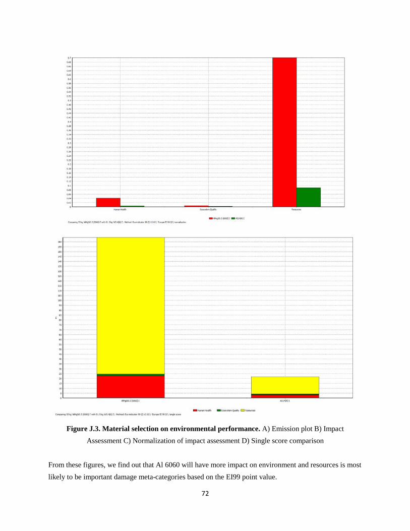
72
Figure J.3. Material selection on environmental performance. A) Emission plot B) Impact
Assessment C) Normalization of impact assessment D) Single score comparison From these figures, we find out that Al 6060 will have more impact on environment and resources is most likely to be important damage meta-categories based on the EI99 point value.

73
APPENDIX K ENGINEERING DRAWING

74

75

76

77

78

79

80

81

82

83

84

85

86

87

88

89

90

91

92
APPENDIX L BILL OF MATERIAL Mcmater-carr
Name Item Number Quantity Price Length Total price
Pneumatics Stainless Steel Air Cylinder Pivot-Mount, Double Acting, 1-1/2" Bore, 8" Stroke 6498K679� 2 57.04 114.08
Rod Clevis with Pin for 1-1/2" Bore Stainless Steel Air Cylinder 6498K44 2 5.69 11.38 Pivot Bracket for 1-1/2" Bore, Pivot-Mount Stainless Steel Air Cylinder 6498K73 2 5.08 10.16
Pivot Bracket for 2" & 2-1/2" Bore Stainless Steel Air Cylinder 6498K564 2 8.12 16.24
Subtotal 151.86
Fittings/Pipes Nckl-Pltd Brass Push-to-Connect Tube Fitting 90 Deg Elbow for 1/8" Tube OD X 1/8" NPTF Male Pipe 51495K231 4 3.09 12.36 Nckl-Pltd Brass Push-to-Connect Tube Fitting Tee for 1/8" Tube OD 51495K131 2 3.97 7.94 Crack-Resistant Polyethylene Tubing 1/16" ID, 1/8" OD, .031" Wall Thickness, White 5181K15 1 0.05 50 2.5
Brass Air Tank Valve 1/8" NPT, 1-5/16" Overall Length 8063K31 1 3.09 3.09 White Polypropylene Barbed Tube Fitting Adapter for 1/8" Tube ID X 1/8" NPT Female Pipe 5121K511 1 5.84 5.84
Subtotal 31.73
Water cut plate Multipurpose Aluminum (Alloy 6061) 1/4" Thick, 12" Width, 6' Length 9246K45 3 72.95 218.85 Multipurpose Aluminum (Alloy 6061) 1/2" Thick X 10" Width X 6' Length 8975K108 1 64.39 64.39
Subtotal 283.24
Bearings/collars Steel Ball Bearing Flanged Open for 1/2" Shaft Dia, 1-1/8" OD, 7/16" W 6383K234 16 6.59 105.44
Unhardened Precision Steel Drive Shaft 1/2" OD, 48" Length 1346K19 1 24.41 24.41 One-Piece Clamp-on Shaft Collar Black-Oxide Steel, 1/2" Bore, 1-1/8" OD, 13/32" Width 6435K14 16 1.74 27.84
Subtotal 157.69 Screws Alloy Steel Button Head Socket Cap Screw 1/4"-20 Thread, 1/2" Length 91255A537 2 13.5 100 27 Alloy Steel Button Head Socket Cap Screw 1/4"-20 Thread, 3/4" Length 91255A540 2 8.06 50 16.12 Alloy Steel Button Head Socket Cap Screw 5/16"-18 Thread, 5/8" Length 91255A580 3 9.89 50 29.67

93
Alloy Steel Button Head Socket Cap Screw 5/16"-18 Thread, 1" Length 91255A583 2 9.96 50 19.92 Alloy Steel Button Head Socket Cap Screw 5/16"-18 Thread, 1-1/2" Length 91255A587 3 7.41 10 22.23
Subtotal 114.94
Total 739.46
H.H.Barnum
Name Item Number Quantity Price Length Total price
Frame T-Slots Aluminum Extrusion, 1" X 1", Priced Per Inch. Stocked in 120" lengths 650000 3 0.23 120 82.8 T-Slots Aluminum Extrusion, 1.5" X 1.5", Priced Per Inch. Stocked in 120" lengths 650005 4 0.57 120 273.6 T-Slots 15 Series Bracket, inside corner, 3 x 3 x 1.3 inches, 4 hole 653135 4 4.59 18.36 T-Slots Transition Bracket, from 10 Series to 15 Series, inside corner, 3 x 3 x 0.875 inches, 4 hole 653269 6 4.42 26.52 T-Slots Transition Bracket, from 10 Series to 15 Series, inside corner, 1 x 1 x 0.875 inches 653272 2 2.95 5.9 T-Slots 15 Series Bracket, slotted inside corner, 1.5 x 1.5 x 1.3 inches, 2 hole 653133 6 3.91 23.46
10 SERIES / 25 SERIES - 2 Hole Slotted Corner Bracket 653126 6 3.8 22.8
Economy T-Nut for 1/4-20 651163 200 0.23 46
Economy T-Nut for 5/16-18 651097 300 0.28 84
Subtotal 583.4
Wheel
5" Flange Mount Swivel Caster w/ Br 655249 4 22.51 90.04
15 S Flange Mount Caster Base Plate 655287 4 20.13 80.52
5/16-18 x 7/8" SHCS & Economy T-Nut 651205 8 0.57 4.56
Subtotal 175.1
Total 758.5

94
APPENDIX M WATER-JET CUT DRAWING

95

96

97

98

99

100

101

102

103

104
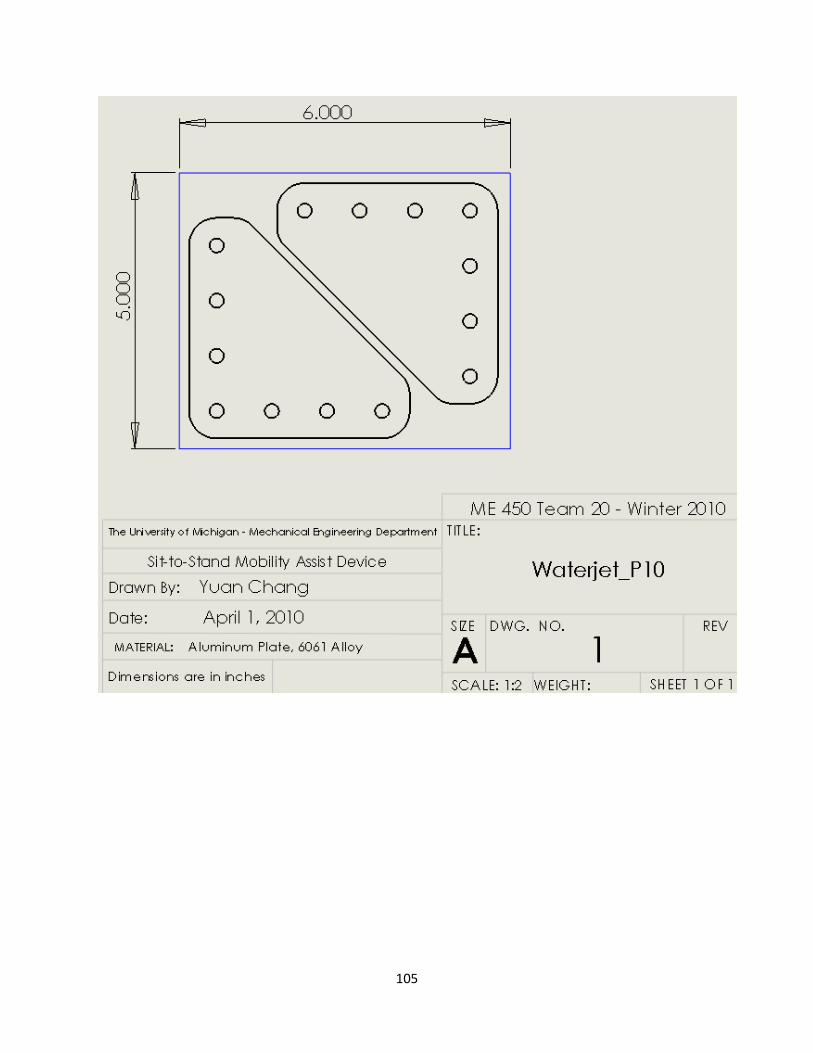
105

106

107

108

109

110

111

112

113

114

115
APPENDIX N DESCRIPTION OF ENGINEERING CHANGES SINCE DESIGN REVIEW #3 This section details the design prior to Design Review #3 and includes the frame design and lifting mechanism. After Design Review #3 the entire concept was redesigned. The final design has already been presented in the body of the report; see Concept Description (pg.21) and Final Design (pg 33).
Frame Design The frame has been designed is SolidWorks as a water-jet cut aluminum plate. This does not coincide with the description in the parameter analysis section, but will present the general shape of the frame. Further analysis and manufacturing decisions need to be made in order to finalize the frame design. The current frame is presented in Figure N.1 below.
Figure N.1. CAD drawing for frame design
Lifting Mechanism The lifting mechanism has been the element of the final design that has been most developed to this point. The 4-bar linkage system has been carefully designed along with the pneumatic cylinder placement in order to optimize the travel distance of the 4-bar linkage mechanism. The cross bar is used to synchronize two linkages as well as supplying a platform for users to rest on. The lifting mechanism can be found in Figure N.2 below,.

116
Figure N.2. CAD drawings for lifting mechanism
A simplified version of the lifting mechanism can be found below in Figure N.3. The input arm will rotate from the position on the left to the position on the right when the pneumatic cylinder is engaged. The position on the left represents the sitting position and the position on the right represents the standing position. It should also be noted that the lifting mechanism will also provide the un-weighting force when in the standing position. The additional force provided by the pneumatic cylinder to the 4-bar linkage system in the upwards direction will support partial weight of the user.
Figure N.3. Left – Sitting lifting mechanism position. Right – Standing lifting mechanism position
Rapid Prototyping Following Design Review #3 we developed rapid prototypes of our design using K’nex building toys. This process was very beneficial, as it exposed strengths and weaknesses of our design that were unforeseen in the Solidworks model. The location of the four-bar mechanism resulted in a top heavy design and extreme bending at the top of the frame. Because of the shortcomings of our initial design, we went back to our original linkage designs and chose a design with lower ground locations. We then created a new rapid prototype of the design and further optimized the location of the grounds and length

117
of the linkage arms using the K’nex model. Figure N.4 below presents the initial K’nex model on the left and final K’nex model on the right.
Figure N.4. Left – Initial K’nex prototype. Right – Final K’nex prototype.