smk 2 installation guide - extron electronics · 1 mpor t ant: o to ww . extr on.com for th e...
TRANSCRIPT
1
IMPORTANT:
Go to www.extron.com for the
complete user guide and installation
instructions before connecting the
product to the power source.www.extron.com
SMK 2 • Installation Guide
Overview
ATTENTION:• All structural steps and electrical installation must be performed by qualified personnel in accordance with local and
national building codes and electrical codes.• Toute étape structurelle et installation électrique, doit être effectuée par un personnel qualifié, conformément aux codes du
bâtiment, aux codes incendie et sécurité, et aux codes électriques, locaux et nationaux.
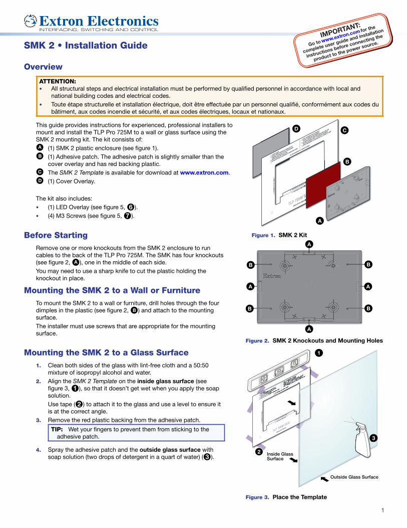
This guide provides instructions for experienced, professional installers to mount and install the TLP Pro 725M to a wall or glass surface using the SMK 2 mounting kit. The kit consists of:
A (1) SMK 2 plastic enclosure (see figure 1).
B (1) Adhesive patch. The adhesive patch is slightly smaller than the cover overlay and has red backing plastic.
C The SMK 2 Template is available for download at www.extron.com.
D (1) Cover Overlay.
The kit also includes:• (1) LED Overlay (see figure 5, 6).• (4) M3 Screws (see figure 5, 7).
A
B
CD
Figure 1. SMK 2 KitBefore StartingRemove one or more knockouts from the SMK 2 enclosure to run cables to the back of the TLP Pro 725M. The SMK has four knockouts (see figure 2, A), one in the middle of each side.You may need to use a sharp knife to cut the plastic holding the knockout in place.
Mounting the SMK 2 to a Wall or FurnitureTo mount the SMK 2 to a wall or furniture, drill holes through the four dimples in the plastic (see figure 2, B) and attach to the mounting surface.The installer must use screws that are appropriate for the mounting surface.
B
A
B
A
B
B
A
A
Figure 2. SMK 2 Knockouts and Mounting Holes
33
1
Outside Glass Surface
Inside GlassSurface
2
Figure 3. Place the Template
Mounting the SMK 2 to a Glass Surface
1. Clean both sides of the glass with lint-free cloth and a 50:50 mixture of isopropyl alcohol and water.
2. Align the SMK 2 Template on the inside glass surface (see figure 3, 1), so that it doesn’t get wet when you apply the soap solution.Use tape (2) to attach it to the glass and use a level to ensure it is at the correct angle.
3. Remove the red plastic backing from the adhesive patch.
TIP: Wet your fingers to prevent them from sticking to the adhesive patch.
4. Spray the adhesive patch and the outside glass surface with soap solution (two drops of detergent in a quart of water) (3).

2 © 2018 Extron Electronics All rights reserved. All trademarks mentioned are the property of their respective owners. www.extron.com
SMK 2 • Installation Guide (Continued)
5. Carefully align the bottom of the adhesive patch with the line on the template that says Bottom of Adhesive Patch Here (see figure 3, 4).You can slide the adhesive patch quite easily while it is still wet.
6. Use a credit card or similar flat edge to remove any air bubbles and a cloth to absorb excess liquid.
7. Remove the clear plastic backing from the other side of the adhesive patch and wet the surface.
8. While the adhesive patch is still wet, align the rear face, bottom edge of the SMK 2 with the line on the template that says Bottom of SMK Here (5).
9. Allow the adhesive to cure at least 24 hours before attaching the touchpanel.
10. Remove the paper template.
TOP
Mounting Plate
LED Overlay
TLP Pro 725MTLP Pro 72TL
7
6
11Back View
9
9
8
10
Figure 5. Mounting the TLP Pro 725M
Mounting the Cover Overlay (Optional)The cover overlay is not required for mounting the touchpanel but can improve the aesthetics of the SMK 2 when it is viewed through the window from inside the conference room. 1. Spray the inside surface of the glass with the soap solution.2. Remove the paper backing from the cover overlay.
TIP: Wet your fingers to prevent them sticking to the adhesive patch.
3. Center the cover overlay behind the SMK 2 enclosure.4. Use a credit card or similar flat edge to remove any air
bubbles and a cloth to absorb excess liquid.
Mounting the TLP Pro 725MMake sure the adhesive securing the SMK 2 to the glass has dried. Extron recommends waiting at least 24 hours before attaching the touchpanel.1. Remove the paper backing and attach the LED overlay
to the back of the TLP Pro 725M (see figure 5, 6). This overlay covers the rear panel LEDs so that they do not cause a distraction inside the conference room.
2. Run an Ethernet cable to the SMK 2. Pass the cable through the mounting plate.
3. Fasten the mounting plate to the SMK 2 using the four M3 screws provided (7). Use the holes marked EU on the mounting plate.
4. Attach the Ethernet cable to the LAN/PoE input on the TLP Pro 725M rear panel (see the TLP Pro 725 Series and TLP Pro 1025 Series User Guide). Pass the cable through the gap left by removing the tab (see Before Starting on the previous page).
5. The mounting plate has four hooks (8), one on each corner. Position the TLP Pro 725M so that these hooks fit into the four slots on the rear panel of the touchpanel (see the TLP Pro 725 Series and TLP Pro 1025 Series User Guide).
6. Slide the TLP Pro 725M down slightly so that the hooks are seated securely in the slots.
7. The tongue at the bottom of the mounting plate (9) sits in the groove in the bottom of the touchpanel (see inset, ¢). Fasten the touchpanel to the mounting plate by tightening the lock screw (£).
54
Figure 4. Attach Adhesive Patch and SMK 2 to the Glass
68-3233-01 Rev. A02 18