soa preamp performance: theoretical modeling - ieee 802 · • vs. an apd receiver, the soa demux...
TRANSCRIPT

1
SOA preamp performance: theoretical modelingRene Bonk, Dora van Veen, Vincent Houtsma, Bell Labs
Ed Harstead, member Fixed Networks CTO
January 2017

2
Receiver Model for SOA+Filter+PIN / APD
• Analytical Rx model for SOA+filter+PIN and APD (modified from “G. Agrawal, fiber-optic communication systems”)
• Different noise contributions included• Shot noise (signal , SOA-ASE (both polarization), dark current)• Thermal noise of TIA and electronic amplifier noise • APD: excess noise from multiplication process• SOA: signal-ASE and ASE-ASE beat noise
• Extinction ratio of signal is 6dB
• SOA: power independent and time independent small-signal gain and noise figure• APD: fixed multiplication factor and excess noise
• Rectangular-shaped filters with insertion loss
• TIA and electronic amplifier noise for PIN and APD receivers assumed to be identical for all receiver types• TIA and Si/Ge APD (M=12, Fexcess = 3.22) modeled according to SiFotonics contributions pan_3ca_1_0916.pdf
• BER calculated including all noise contributions

3
Parameter for Receiver Model for SOA+Filter+PIN / APD
Parameter Value
APD/PIN Quantum Efficiency 0.7
Signal Wavelength 1270nm
Noise Factor of Electrical Amplifier 2
Load Resistor of TIA 150Ω
Electrical Bandwidth 18.75GHz for 25Gbit/s operation
SOA Gain 17dB
Device Temperature 300K
Dark Current 60nA
BER Threshold 1E-3
Si/Ge and InAlAs APD Multiplication Factor M 12
Si/Ge APD Excess Noise Factor Fexcess @ M = 12 3.22 (according to SiFotonics, see pan_3ca_1_0916.pdf)
InAlAs APD Excess Noise Factor Fexcess @ M = 12 5.69
Extinction Ratio at Rx 6dB

4
4x25G OLT receiver sensitivity: TDM co-existence, λ0
1270 nm MR
10G/25G APD Rx
λ1 25G PIN Rx
λ2 25G PIN Rx
λ3 25G PIN Rx
APD receiver SOA+PIN receiver
1270 nm MR
10G/25G PIN Rx
20 nm wide
λ1 25G PIN Rx
λ2 25G PIN Rx
λ3 25G PIN Rx
SOA
How much receiver sensitivity benefit (measured at R) does the SOA+PIN implementation bring relative to the APD?
≤1280 nm
λd
em
ux
TFF diplexer
TFF demux0.5 dB
λd
em
ux
TFF ≥1260 nm
0.5 dB
R RTFF
diplexer 0.5 dB
TFF demux
>1280 nm
≤1280 nm
SOA

5
4x25G OLT receiver sensitivity: TDM co-existence, λ0-- Results
APD, M = 12, Fexcess = 7.6dB
SOA+Filter+PINNFSOA 7dB
NFSOA 8dB
20nm
APD, M = 12, Fexcess = 5.1dB
SOA / PIN Advantage @ 20nm
NF = 7dB F = 7.6dB 1.3dB
F = 5.1dB 0.1dB
NF = 8dB F = 7.6dB 0.4dB
F = 5.1dB -0.8dB
• Rx-filter loss included • 20nm optical filter bandwidth in SOA-based Rx• SOA noise figure of 7dB and 8dB • Si/Ge APD: M = 12 and Fexcess = 3.22 (5.1dB)• InAlAs APD: M = 12 and Fexcess = 5.69 (7.6dB)• No margins included for aging, etc…
@ BER 1E-3 and 25Gbit/s
Wavelength 1270 nm, ER 6dB
6
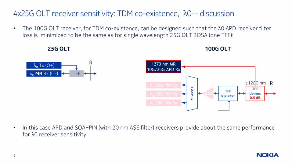
• The 100G OLT receiver, for TDM co-existence, can be designed such that the λ0 APD receiver filter loss is minimized to be the same as for single wavelength 25G OLT BOSA (one TFF):
• In this case APD and SOA+PIN (with 20 nm ASE filter) receivers provide about the same performance for λ0 receiver sensitivity
4x25G OLT receiver sensitivity: TDM co-existence, λ0-- discussion
1270 nm MR
10G/25G APD Rx
λ1 25G PIN Rx
λ2 25G PIN Rx
λ3 25G PIN Rxλ
de
mu
x
TFF diplexer
TFF demux0.5 dB
R≤1280 nm
SOA
λ0 Tx (O+)
λ0 MR Rx (O-) TFF
R
25G OLT 100G OLT

7
4x25G OLT receiver sensitivity: …λ3
λ0 25G APD Rx
λ1 25G APD Rx
λ2 25G APD Rx
λ3 25G APD Rx
λd
em
ux
2.5
dB
TFF diplexer0.5 dB
1270 nm 10G Rx
TFF demux0.5 dB
Bandpass = 400 - 600 GHz
λ0 25G PIN Rx
λ1 25G PIN Rx
λ2 25G PIN Rx
λ3 25G PIN Rx
λd
em
ux
2.5
dB
TFF diplexer0.5 dB
SOA
1270 nm 10G Rx
TFF demux0.5 dB
How much receiver sensitivity benefit (measured at R) does the SOAdemuxPIN implementation bring relative to the APD?
APD receivers SOA+PIN receivers
R R
WDM co-existence case shown
8
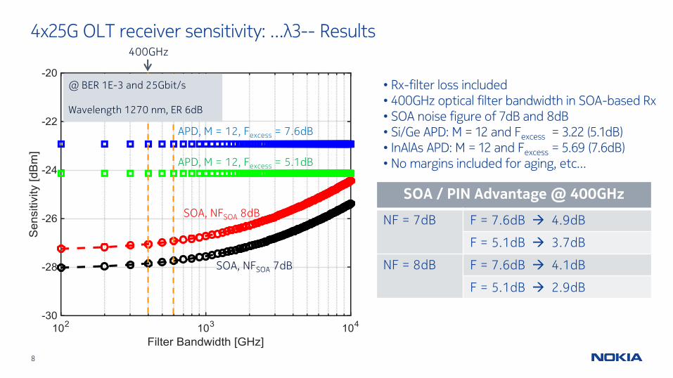
4x25G OLT receiver sensitivity: …λ3-- Results
APD, M = 12, Fexcess = 7.6dB
SOA, NFSOA 7dB
SOA, NFSOA 8dB
APD, M = 12, Fexcess = 5.1dB
SOA / PIN Advantage @ 400GHz
NF = 7dB F = 7.6dB 4.9dB
F = 5.1dB 3.7dB
NF = 8dB F = 7.6dB 4.1dB
F = 5.1dB 2.9dB
• Rx-filter loss included • 400GHz optical filter bandwidth in SOA-based Rx• SOA noise figure of 7dB and 8dB • Si/Ge APD: M = 12 and Fexcess = 3.22 (5.1dB)• InAlAs APD: M = 12 and Fexcess = 5.69 (7.6dB)• No margins included for aging, etc…
@ BER 1E-3 and 25Gbit/s
Wavelength 1270 nm, ER 6dB
400GHz

9
• Vs. an APD receiver, the SOAdemuxPIN receiver with 400-600 GHz ASE filter provides appreciable sensitivity benefit, between ~ 3-5 dB.
• Therefore this confirms expectations that SOA preamps will be used in 100G OLTs.
• The same SOAdemuxPIN performance also applies to λ1 - λ3 for the TDM co-existence case:
4x25G OLT receiver sensitivity: …λ3-- discussion
1270 nm MR
10G/25G APD Rx
λ1 25G PIN Rx
λ2 25G PIN Rx
λ3 25G PIN Rx
λd
em
ux
2.5
dB
TFF diplexer
0.5 dB
TFF demux0.5 dB
R≤1280 nm
SOA
λ0 25G PIN Rx
λ1 25G PIN Rx
λ2 25G PIN Rx
λ3 25G PIN Rx
λd
em
ux
2.5
dB
TFF diplexer0.5 dB
SOA
1270 nm 10G Rx
TFF demux0.5 dB R
TDM co-existence WDM co-existence

10

11
Backup
12
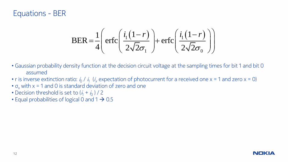
Equations - BER
1 1
1 0
1 11BER erfc erfc
4 2 2 2 2
i r i r
• Gaussian probability density function at the decision circuit voltage at the sampling times for bit 1 and bit 0 assumed
• r is inverse extinction ratio: i0 / i1 (ix expectation of photocurrent for a received one x = 1 and zero x = 0)• σx with x = 1 and 0 is standard deviation of zero and one • Decision threshold is set to (i1 + i0 ) / 2• Equal probabilities of logical 0 and 1 0.5
13
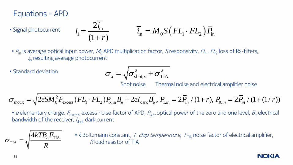
Equations - APD
• Signal photocurrent in
1 in 0 1 2 in
2
(1 )
ii i M S FL FL P
r
• Pin is average optical input power, M0 APD multiplication factor, S responsivity, FL1, FL2 loss of Rx-filters,iin resulting average photocurrent
• Standard deviation 2 2
shot,x TIAx
2
shot,x 0 excess 1 2 x,in e dark e 1, 0,2 ( ) 2 , 2 / (1 ), 2 / (1 (1/ ))in in in ineSM F FL FL P B eI B P P r P P r
• e elementary charge, Fexcess excess noise factor of APD, Px,in optical power of the zero and one level, Be electrical bandwidth of the receiver, Idark dark current
Shot noise Thermal noise and electrical amplifier noise
TIA
TIA
4 ekTB F
R
• k Boltzmann constant, T chip temperature, FTIA noise factor of electrical amplifier, R load resistor of TIA
14
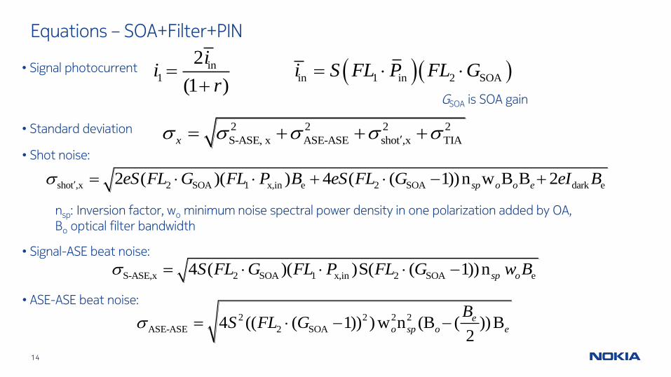
Equations – SOA+Filter+PIN
• Signal photocurrent in
1 in 1 in 2 SOA
2
(1 )
ii i S FL P FL G
r
GSOA is SOA gain
• Standard deviation 2 2 2 2
S-ASE, x ASE-ASE shot ,x TIAx
shot ,x 2 SOA 1 x,in e 2 SOA dark e2 ( )( ) 4 ( ( 1))n w B B 2sp o o eeS FL G FL P B eS FL G eI B
nsp: Inversion factor, wo minimum noise spectral power density in one polarization added by OA, Bo optical filter bandwidth
S-ASE,x 2 SOA 1 x,in 2 SOA e4 ( )( )S( ( 1))nsp oS FL G FL P FL G w B • Signal-ASE beat noise:
• Shot noise:
• ASE-ASE beat noise:2 2 2 2
ASE-ASE 2 SOA4 (( ( 1)) ) w n (B ( ))B2
e
o sp o e
BS FL G