soundacoustics ha600/75 hybrid absorber/diffuser€¦ · acoustic innovation the unique patented...
TRANSCRIPT

Application: Hybrid broadband selective diffuser/absorber
Frequency Characteristics: 160Hz - 20Khz
Installation: Staple gun or adhesive
Dimensions: 600 x 600 x 75mm
Acoustic Innovation
The unique patented HA600/75 hybrid absorber/diffuser panel offers
selective absorption of lower frequencies and diffusion of high fre-
quencies. In a critical listening environment these characteristics as-
sist in creating a controlled acoustic environment whilst retaining a
natural sense of space.
The HA600/75 acoustic panel is designed to receive a shallow radius
polycarbonate insert, diffusing frequencies above 450Hz. The diffuser
increases the low frequency absorption of the panel, down to a very
useful 150Hz. Should you require just a straight absorption panel, the
diffuser can be easily removed, the ultimate in flexibility.
Creating the ideal space
Professional recording studios typically employ resonator type panels (usually perforated or slat timber ), in order to absorb lower fre-
quencies and reflect high frequencies, in both recording and control rooms. The HA600/75 offers very similar performance to a typical
resonator panel, but in a far more convenient and flexible form. The HA600/75 is also ideal for audiophiles looking to improve the accu-
racy of a listening room. Used in conjunction with a corner bass trap such as the RAM400/1000, the HA600/75 provides a complete
balanced acoustic solution for professional or home applications alike.
A perfect balance of absorption and diffusion
Without the diffuser insert (see graph below) the HA600/75 functions as a quality broadband absorber, providing the performance ex-
pected of a 75mm thick panel. The ability of acoustic foam to absorb lower frequencies is directly related to thickness. With the diffuser
insert installed, a smooth roll-off of high frequency absorption occurs above 400Hz.
SoundAcoustics HA600/75 Hybrid Absorber/Diffuser

At lower frequencies the diffuser insert has been designed to behave as a resonator panel, enhancing low frequency absorption, achiev-
ing a considerable 70% absorption at 160 Hertz (see graph above). SoundAcoustics testing and evaluation takes place at the NATA
accredited acoustic laboratory at the Royal Melbourne Institute of Technology in Melbourne.
Get creative!
The clear diffuser provides the perfect opportunity for customization. For that extra splash of colour, insert a sheet of coloured card-
board (or similar) behind the diffuser. Posters also look great mounted behind the polycarbonate insert. An inexpensive way to create
your own look, or match your existing decor.
The standard colour is charcoal grey but panels can be flock coated (suede fibre type finish) in a range of custom colours at additional
cost.
10 year warranty
SoundAcoustics products are manufactured in Melbourne, Australia from the highest quality combustion modified polyurethane foam
and carry a ten year factory warranty. For more information see: www.soundacoustics.com.au
ph: 03 9410 9335 email: [email protected]
soundacoustics.com.au creating listening environments
Page 1 of 6 Report Number 121I/09-041/JW
Checked by: PD 11/3/2009
REPORT ON THE DETERMINATION OF SOUND
ABSORPTION COEFFICIENTS OF SOUNDACOUSTICS HYBRID
ACOUSTIC PANELS WITH ACRYLIC DIFFUSER INSTALLED IN A
REVERBERATION ROOM.
Testing Procedure: AS ISO 354 - 2006
Testing Laboratory: Applied Acoustics Laboratory
RMIT University, School of Applied Sciences
Melbourne, Victoria 3000, Australia
NATA Accreditation Number 1421
Client: SoundAcoustics
Northcote, Victoria 3070
Australia
Date of Test: 17th February 2009
Date of Report: 6th March 2009
Report Number: 121I/09-041/JW
Testing Officer: John Watson
John Watson
Approved NATA Signatory
This document issued in compliance with NATA’s
accreditation requirements.
Accredited for compliance with ISO/IEC 17025
Page 2 of 6 Report Number 121I/09-041/JW
Checked by: PD 11/3/2009
REPORT ON THE DETERMINATION OF SOUND
ABSORPTION COEFFICIENTS OF SOUNDACOUSTICS HYBRID
ACOUSTIC PANELS WITH ACRYLIC DIFFUSER INSTALLED IN A
REVERBERATION ROOM.
1. INTRODUCTION
The tests described in this report were carried out at the request of the SoundAcoustics to
determine the sound absorption coefficients of a sample of Sound Acoustics Hybrid Acoustic
Panels with acrylic diffuser installed.
The tests were carried out using the reverberation room of the Applied Physics Discipline,
The Royal Melbourne Institute of Technology Limited.
Testing has been carried out in accordance with AS ISO 354–2006 “Acoustics: Measurement
of sound absorption in a reverberation room”. At the request of the client the weighted sound
absorption coefficient αw has been determined in accordance with AS ISO 11654-1997
“Acoustics: Sound Absorbers for Use in Buildings - Rating of sound absorption”.
The equipment used to perform these tests has been calibrated at an accredited laboratory and
is in current calibration.
2. TEST FACILITIES AND PROCEDURES
2.1 Facilities The reverberation room is of pentagonal plan with the ceiling inclined with
respect to the floor. No two room dimensions are equal or in the ratio of small whole
numbers. The volume of the room is 200.0 cubic metres. A sufficiently diffuse sound field is
established by the inclusion of 17 stationary diffusing boards of panelboard, each of one-
sided area approximately one square metre and suspended with random orientation. The total
two-sided area of the diffusing elements is 0.16 of the total boundary surface area of the
room. Previous tests carried out in the room have established that diffusivity of the room
sound field is acceptable.
The total surface area of the room boundaries and diffusing elements is 235.6 square metres.
2.2 Generation of sound field The test signals is random noise, band limited to a frequency
range of 40Hz to 6300Hz. Three individual loudspeaker positions are used to excite the
sound field in the reverberation chamber. The signal is fed to each loudspeaker in turn.
2.3 Receipt of signals Four microphones each mounted in statistically independent locations
in the reverberation room are used to measure the sound field decays in the room. Ten sound
decays are obtained at each of the twelve loudspeaker/microphone combinations, thus
representing 120 decays for each frequency band.
The microphone signal is relayed via a microphone amplifier, to a Bruel & Kjaer 3560 Pulse
Multi Analyser System. The Pulse analyser is interfaced to a personal computer. A program
running on the personal computer allows the determination of the reverberation time from the
sound decays in accordance with the standard. The measuring equipment has been calibrated
by an external laboratory, and is in current calibration.
Page 4 of 6 Report Number 121I/09-041/JW
Checked by: PD 11/3/2009
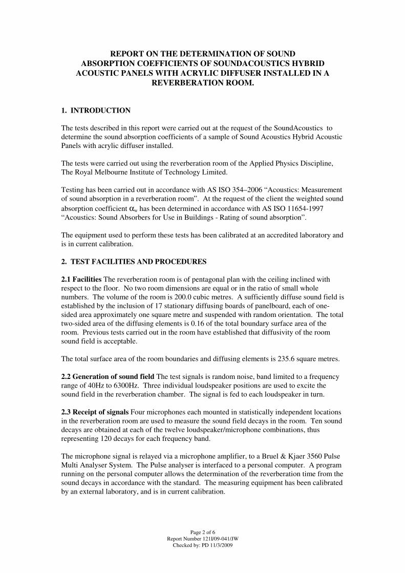
Figure 3: Sound Acoustics Hybrid Acoustic Panels with acrylic diffuser installed in the
reverberation chamber.
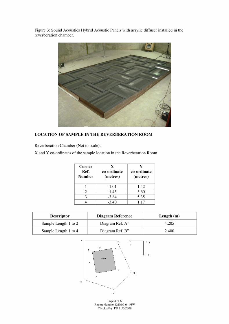
LOCATION OF SAMPLE IN THE REVERBERATION ROOM
Reverberation Chamber (Not to scale):
X and Y co-ordinates of the sample location in the Reverberation Room
Corner
Ref.
Number
X
co-ordinate
(metres)
Y
co-ordinate
(metres)
1 -1.01 1.42
2 -1.45 5.60
3 -3.84 5.35
4 -3.40 1.17
Descriptor Diagram Reference Length (m)
Sample Length 1 to 2 Diagram Ref. A” 4.205
Sample Length 1 to 4 Diagram Ref. B” 2.400

Page 5 of 6 Report Number 121I/09-041/JW
Checked by: PD 11/3/2009
4. RESULTS
The mean reverberation times at each frequency for the empty room, T60e, the room with the
sample installed, T60e+s, the sound absorption coefficient and the 95% confidence interval are
provided in Table 1. The results are rounded to 0.01. The 95% confidence interval for each
frequency is determined from the standard deviation of the reverberation times of the empty
room and the room with the sample. The k factor used to determine the 95% Confidence
interval is 2.201.
The results for the sample are detailed in Table 1 and Graph 1 of this report.
Test conditions:
Room Empty Air temperature 23.0oC,
Relative Humidity 47%
Barometric Pressure 0.7638 metre of mercury.
Room with Sample Air temperature 23.2oC,
Relative Humidity 49%
Barometric Pressure 0.7639 metres of mercury
Table 1: Reverberation times and Sound Absorption Coefficients of Sound Acoustics
Hybrid Acoustic Panels with acrylic diffuser installed.
Octave
Centre
Frequency
Bands, Hz
Average
RT’s for
empty room.
T60e
Average
RT’s for
room. with
sample
T60e+s
Sound
Absorption
Coefficient
αs
95%
Confidence
Interval for
αs
100 7.238 4.235 0.31 0.06
125 6.355 4.063 0.28 0.05
160 8.571 2.904 0.72 0.06
200 8.841 2.914 0.73 0.07
250 8.778 2.333 1.00 0.08
315 7.864 2.197 1.04 0.04
400 7.054 2.141 1.03 0.05
500 6.488 2.177 0.97 0.04
630 6.341 2.323 0.87 0.05
800 6.032 2.497 0.74 0.03
1000 5.461 2.659 0.61 0.02
1250 5.054 2.708 0.54 0.02
1600 4.415 2.581 0.51 0.02
2000 3.887 2.379 0.52 0.02
2500 3.448 2.179 0.54 0.02
3150 2.933 1.962 0.55 0.02
4000 2.364 1.717 0.52 0.02
5000 1.951 1.494 0.53 0.03
Page 6 of 6 Report Number 121I/09-041/JW
Checked by: PD 11/3/2009
The weighted sound absorption coefficient αw of the sample determined in accordance with
AS ISO 11654-1997 “Acoustics: Sound Absorbers for Use in Buildings - Rating of sound
absorption” is:
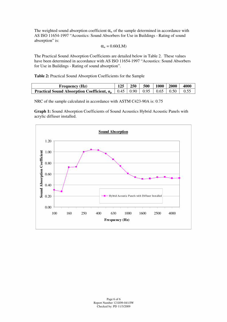
αw = 0.60(LM)
The Practical Sound Absorption Coefficients are detailed below in Table 2. These values
have been determined in accordance with AS ISO 11654-1997 “Acoustics: Sound Absorbers
for Use in Buildings - Rating of sound absorption”.
Table 2: Practical Sound Absorption Coefficients for the Sample
Frequency (Hz) 125 250 500 1000 2000 4000
Practical Sound Absorption Coefficient, αp 0.45 0.90 0.95 0.65 0.50 0.55
NRC of the sample calculated in accordance with ASTM C423-90A is: 0.75
Graph 1: Sound Absorption Coefficients of Sound Acoustics Hybrid Acoustic Panels with
acrylic diffuser installed.
Sound Absorption
0.00
0.20
0.40
0.60
0.80
1.00
1.20
100 160 250 400 630 1000 1600 2500 4000
Frequency (Hz)
So
un
d A
bso
rp
tio
n C
oeff
icie
nt
Hybrid Acoustic Panels with Diffuser Installed

Page 1 of 6 Report Number 121I/09-042/JW
Checked by: PD 11/3/2009
REPORT ON THE DETERMINATION OF SOUND
ABSORPTION COEFFICIENTS OF SOUNDACOUSTICS HYBRID
ACOUSTIC PANELS WITH ACRYLIC DIFFUSER REMOVED IN A
REVERBERATION ROOM.
Testing Procedure: AS ISO 354 - 2006
Testing Laboratory: Applied Acoustics Laboratory
RMIT University, School of Applied Sciences
Melbourne, Victoria 3000, Australia
NATA Accreditation Number 1421
Client: SoundAcoustics
Northcote, Victoria 3070
Australia
Date of Test: 17th February 2009
Date of Report: 6th March 2009
Report Number: 121I/09-042/JW
Testing Officer: John Watson
John Watson
Approved NATA Signatory
This document issued in compliance with NATA’s
accreditation requirements.
Accredited for compliance with ISO/IEC 17025
Page 2 of 6 Report Number 121I/09-042/JW
Checked by: PD 11/3/2009
REPORT ON THE DETERMINATION OF SOUND
ABSORPTION COEFFICIENTS OF SOUNDACOUSTICS HYBRID
ACOUSTIC PANELS WITH ACRYLIC DIFFUSER REMOVED IN A
REVERBERATION ROOM.
1. INTRODUCTION
The tests described in this report were carried out at the request of the SoundAcoustics to
determine the sound absorption coefficients of a sample of Sound Acoustics Hybrid Acoustic
Panels with acrylic diffuser removed.
The tests were carried out using the reverberation room of the Applied Physics Discipline,
The Royal Melbourne Institute of Technology Limited.
Testing has been carried out in accordance with AS ISO 354–2006 “Acoustics: Measurement
of sound absorption in a reverberation room”. At the request of the client the weighted sound
absorption coefficient αw has been determined in accordance with AS ISO 11654-1997
“Acoustics: Sound Absorbers for Use in Buildings - Rating of sound absorption”.
The equipment used to perform these tests has been calibrated at an accredited laboratory and
is in current calibration.
2. TEST FACILITIES AND PROCEDURES
2.1 Facilities The reverberation room is of pentagonal plan with the ceiling inclined with
respect to the floor. No two room dimensions are equal or in the ratio of small whole
numbers. The volume of the room is 200.0 cubic metres. A sufficiently diffuse sound field is
established by the inclusion of 17 stationary diffusing boards of panelboard, each of one-
sided area approximately one square metre and suspended with random orientation. The total
two-sided area of the diffusing elements is 0.16 of the total boundary surface area of the
room. Previous tests carried out in the room have established that diffusivity of the room
sound field is acceptable.
The total surface area of the room boundaries and diffusing elements is 235.6 square metres.
2.2 Generation of sound field The test signals is random noise, band limited to a frequency
range of 40Hz to 6300Hz. Three individual loudspeaker positions are used to excite the
sound field in the reverberation chamber. The signal is fed to each loudspeaker in turn.
2.3 Receipt of signals Four microphones each mounted in statistically independent locations
in the reverberation room are used to measure the sound field decays in the room. Ten sound
decays are obtained at each of the twelve loudspeaker/microphone combinations, thus
representing 120 decays for each frequency band.
The microphone signal is relayed via a microphone amplifier, to a Bruel & Kjaer 3560 Pulse
Multi Analyser System. The Pulse analyser is interfaced to a personal computer. A program
running on the personal computer allows the determination of the reverberation time from the
sound decays in accordance with the standard. The measuring equipment has been calibrated
by an external laboratory, and is in current calibration.

Page 4 of 6 Report Number 121I/09-042/JW
Checked by: PD 11/3/2009
Figure 3: Sound Acoustics Hybrid Acoustic Panels with acrylic diffuser removed in the
reverberation chamber.
LOCATION OF SAMPLE IN THE REVERBERATION ROOM
Reverberation Chamber (Not to scale):
X and Y co-ordinates of the sample location in the Reverberation Room
Corner
Ref.
Number
X
co-ordinate
(metres)
Y
co-ordinate
(metres)
1 -1.01 1.42
2 -1.45 5.60
3 -3.84 5.35
4 -3.40 1.17
Descriptor Diagram Reference Length (m)
Sample Length 1 to 2 Diagram Ref. A” 4.205
Sample Length 1 to 4 Diagram Ref. B” 2.400

Page 5 of 6 Report Number 121I/09-042/JW
Checked by: PD 11/3/2009
4. RESULTS
The mean reverberation times at each frequency for the empty room, T60e, the room with the
sample installed, T60e+s, the sound absorption coefficient and the 95% confidence interval are
provided in Table 1. The results are rounded to 0.01. The 95% confidence interval for each
frequency is determined from the standard deviation of the reverberation times of the empty
room and the room with the sample. The k factor used to determine the 95% Confidence
interval is 2.201.
The results for the sample are detailed in Table 1 and Graph 1 of this report.
Test conditions:
Room Empty Air temperature 23.0oC,
Relative Humidity 47%
Barometric Pressure 0.7638 metre of mercury.
Room with Sample Air temperature 23.2oC,
Relative Humidity 48%
Barometric Pressure 0.7640 metres of mercury
Table 1: Reverberation times and Sound Absorption Coefficients of Sound Acoustics
Hybrid Acoustic Panels with acrylic diffuser removed.
Octave
Centre
Frequency
Bands, Hz
Average
RT’s for
empty room.
T60e
Average
RT’s for
room. with
sample
T60e+s
Sound
Absorption
Coefficient
αs
95%
Confidence
Interval for
αs
100 7.238 4.736 0.23 0.05
125 6.355 4.573 0.19 0.04
160 8.571 4.447 0.34 0.04
200 8.841 4.518 0.34 0.05
250 8.778 3.490 0.55 0.03
315 7.864 2.844 0.71 0.05
400 7.054 2.411 0.87 0.04
500 6.488 2.183 0.96 0.05
630 6.341 2.130 0.99 0.04
800 6.032 2.190 0.92 0.03
1000 5.461 2.150 0.89 0.04
1250 5.054 2.064 0.91 0.03
1600 4.415 1.922 0.93 0.03
2000 3.887 1.782 0.97 0.03
2500 3.448 1.655 1.00 0.02
3150 2.933 1.512 1.02 0.03
4000 2.364 1.367 0.99 0.03
5000 1.951 1.223 0.99 0.04

Page 6 of 6 Report Number 121I/09-042/JW
Checked by: PD 11/3/2009
The weighted sound absorption coefficient αw of the sample determined in accordance with
AS ISO 11654-1997 “Acoustics: Sound Absorbers for Use in Buildings - Rating of sound
absorption” is:
αw = 0.85(H)
The Practical Sound Absorption Coefficients are detailed below in Table 2. These values
have been determined in accordance with AS ISO 11654-1997 “Acoustics: Sound Absorbers
for Use in Buildings - Rating of sound absorption”.
Table 2: Practical Sound Absorption Coefficients for the Sample
Frequency (Hz) 125 250 500 1000 2000 4000
Practical Sound Absorption Coefficient, αp 0.25 0.55 0.95 0.90 0.95 1.00
NRC of the sample calculated in accordance with ASTM C423-90A is: 0.85
Graph 1: Sound Absorption Coefficients of Sound Acoustics Hybrid Acoustic Panels with
acrylic diffuser removed.
Sound Absorption
0.00
0.20
0.40
0.60
0.80
1.00
1.20
100 160 250 400 630 1000 1600 2500 4000
Frequency (Hz)
So
un
d A
bso
rp
tio
n C
oeff
icie
nt
Hybrid Acoustic Panels with Acrylic diffuser
removedout Diffuser