spar data handling utilities - nasa discussion of how these spar data handling utilities are used in...
TRANSCRIPT

NASA Technical Memorandum 78701
SPAR Data Handling Utilities
Gary L. Giles and Raphael T. Haftka
SEPTEMBER 1978
NASA
https://ntrs.nasa.gov/search.jsp?R=19780023850 2018-06-02T23:39:02+00:00Z

NASA Technical Memorandum 78701
SPAR Data Handling Utilities
Gary L. GilesLangley Research CenterHampton, Virginia
and
Raphael T. HaftkaIllinois Institute of TechnologyChicago, Illinois
NASANational Aeronauticsand Space Administration
Scientific and TechnicalInformation Office
1978

Page intentionally left blank
Page intentionally left blank
CONTENTS
PageSUMMARY 1
INTRODUCTION 1
SPAR TECHNICAL CAPABILITIES 2
SPAR SYSTEM ORGANIZATION 3
DESCRIPTION OF THE SPAR DATA BASE COMPLEX 4Library Structure . 5The Data Set 5Table of Contents 6Master Directory 7
DESCRIPTION OF SPAR DATA HANDLING UTILITIES 8Organization of Data Handling Utilities 9Functions Performed by Data Handling Utilities 10
GUIDE FOR IMPLEMENTING SPAR DATA HANDLING UTILITIES 12
CONCLUDING REMARKS 15
APPENDIX A - SPAR DATA HANDLING ROUTINES CALLED BY USER PROGRAM 16
APPENDIX B - SPAR ROUTINES TO PERFORM DATA HANDLING SUPPORTFUNCTIONS 20
APPENDIX C - ROUTINES TO INITIALIZE SPAR PROCESSORS AND READ USERINPUT 23
APPENDIX D - CONTENTS OF LABELED COMMON BLOCKS 26
APPENDIX E - LISTING OF SAMPLE PROCESSOR 30
APPENDIX F - LISTING FROM INTERACTIVE EXECUTION OF SAMPLE PROCESSOR ... 33
APPENDIX G - DYNAMIC STORAGE ALLOCATION 36
REFERENCES 38
TABLES 39
FIGURES : 42
ill

SUMMARY
The SPAR computer software system is a collection of processors that per-form particular steps in the finite-element structural analysis procedure. Thedata generated by each processor are stored on a data base complex residing onan auxiliary storage device, and these data are then used by subsequent proces-sors. The computer software associated with the data base complex provides ageneral capability and can be used for management of data in programs or systemsother than SPAR.
This report documents the SPAR data handling utilities, which are routinesused to transfer data between the processors and the data base complex. Adetailed description of the data base complex organization is also presented.A discussion of how these SPAR data handling utilities are used in an applica-tion program to perform desired user functions is given with the steps necessaryto convert an existing program to a SPAR processor by incorporating these utili-ties. Finally, a sample SPAR processor is included to illustrate the use of thedata handling utilities. This information can be used (1) to understand moreclearly and to use more productively the existing processors in the SPAR system,(2) to develop new SPAR processors, or (3) to use the capabilities of the datahandling utilities in a system totally unrelated to SPAR.
INTRODUCTION
Large volumes of data for a variety of purposes are generated by finite-element structural analysis procedures. The organization of these data and thebookkeeping methods used to store and retrieve the data are important considera-tions in implementing the procedures as computer programs. Several large compu-ter programs (e.g., NASTRAN® and ATLAS, refs. 1 and 2) contain methods to per-form these data handling functions. Such analysis programs are often used inmore comprehensive systems, as discussed in references 3 and 4. The data con-tent, organization, and handling methods must be carefully defined to providefor communication of data between programs.
The SPAR finite-element structural analysis system (ref. 5) contains adata base complex with a standardized organization of data and a self-containedset of data handling utilities used to access the data. These data handlingutilities were developed by W. D. Whetstone and provide a key capability whichcontributes to the effectiveness of the SPAR analysis system. The computer soft-ware associated with the data handling utilities and data base complex is a gen-eral capability and can be used for management of data in programs or systemsother than SPAR. Data handling functions that can be performed by a SPAR userare described in the SPAR reference manual (ref. 5).
The purpose of the present report is to extend the available documentationof the SPAR system by providing a detailed description of the data base complex

organization and the data handling utilities used to communicate with the database. A general overview of the technical capabilities and organization of theSPAR system is given in the beginning sections of the report. Then the contentsand organization of the data base complex are described. A discussion of howthe data handling utilities perform desired user functions in an applicationprogram is given with detailed descriptions of each of the data handling rou-tines provided in appendixes A to D. A step-by-step procedure to incorporatethese routines into existing programs is given. Finally, a sample program whichcontains these routines is included in appendixes E and F to illustrate the useof the capabilities described herein. This information can be applied to usethe SPAR system more productively, to make additions or modifications to theexisting system, or to use the SPAR data handling utilities and associated pro-graming practices in computer programs totally unrelated to SPAR.
Use of commercial products and names of manufacturers in this report doesnot constitute an official endorsement of such products or manufacturers, eitherexpressed or implied, by the National Aeronautics and Space Administration.
SPAR TECHNICAL CAPABILITIES
SPAR is an analysis system capable of computing static deflections andstresses, natural vibration frequencies and modes, and buckling loads and modeshapes of linear finite-element structural simulations. The structural simula-tions are composed of finite elements connected at specified joints, which canhave three translational and three rotational components of deflection. Finiteelements which are currently available for simulating the stiffness characteris-tics of a structure include axial bars, beams of general cross section, triangu-lar and quadrilateral plates having an option to specify coupled or uncoupledmembrane and bending stiffness, and quadrilateral shear panels. Properties ofthe plates may be specified as layers in a laminate of composite materials, andthere is provision for warping of the quadrilateral plate element. Mass proper-ties of a structure are represented by structural and nonstructural masses asso-ciated with the stiffness elements and by concentrated masses at the joints.Loading data can include any or all of the following categories: point forcesor moments acting at the joints, specified joint motions, inertial loading, ther-mal or pressure loads, and initial strains in individual elements. This tech-nical capability contained in the SPAR system is available for operation onControl Data (CDC) 6000 or CYBER 170 Series, UNIVAC 1100 series (ref. 5), orPrime 400 computer systems (ref. 6).
The finite-element structural analysis procedure is divided into a sequenceof steps or functions which must be performed. The computer code required foreach of these steps is referred to herein as a "processor." Processors areseparate portions of the SPAR system which are selectively executed in a logi-cal sequence to perform a desired analysis. Each processor is designed to per-form a limited, yet distinct and complete, function. The functions of each ofthe processors in the version of SPAR denoted as level 11 are given in table 1.The processors TAB through KG read user input, from element matrices, and assem-ble element matrices into system matrices which represent the overall stiffnessand mass of the structure. Solutions of the system matrix equations are per-formed by INV through PSF. The EIG and DR processors are used for eigensolu-
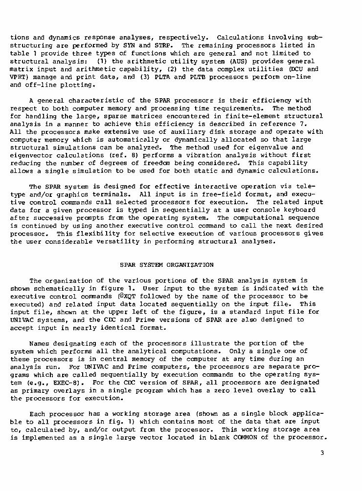
tions and dynamics response analyses, respectively. Calculations involving sub-structuring are performed by SYN and STRP. The remaining processors listed intable 1 provide three types of functions which are general and not limited tostructural analysis: (1) the arithmetic utility system (AUS) provides generalmatrix input and arithmetic capability, (2) the data complex utilities (DCU andVPRT) manage and print data, and (3) PLTA and PLTB processors perform on-lineand off-line plotting.
A general characteristic of the SPAR processors is their efficiency withrespect to both computer memory and processing time requirements. The methodfor handling the large, sparse matrices encountered in finite-element structuralanalysis in a manner to achieve this efficiency is described in reference 7.All the processors make extensive use of auxiliary disk storage and operate withcomputer memory which is automatically or dynamically allocated so that largestructural simulations can be analyzed: The method used for eigenvalue andeigenvector calculations (ref. 8) performs a vibration analysis without firstreducing the number of degrees of freedom being considered. This capabilityallows a single simulation to be used for both static and dynamic calculations.
The SPAR system is designed for effective interactive operation via tele-type and/or graphics terminals. All input is in free-field format, and execu-tive control commands call selected processors for execution. The related inputdata for a given processor is typed in sequentially at a user console keyboardafter successive prompts from the operating system. The computational sequenceis continued by using another executive control command to call the next desiredprocessor. This flexibility for selective execution of various processors givesthe user considerable versatility in performing structural analyses.
SPAR SYSTEM ORGANIZATION
The organization of the various portions of the SPAR analysis system isshown schematically in figure 1. User input to the system is indicated with theexecutive control commands (@XQT followed by the name of the processor to beexecuted) and related input data located sequentially on the input file. Thisinput file, shown at the upper left of the figure, is a standard input file forUNIVAC systems, and the CDC and Prime versions of SPAR are also designed toaccept input in nearly identical format.
Names designating each of the processors illustrate the portion of thesystem which performs all the analytical computations. Only a single one ofthese processors is in central memory of the computer at any time during ananalysis run. For UNIVAC and Prime computers, the processors are separate pro-grams which are called sequentially by execution commands to the operating sys-tem (e.g., EXEC-8). For the CDC version of SPAR, all processors are designatedas primary overlays in a single program which has a zero level overlay to callthe processors for execution.
Each processor has a working storage area (shown as a single block applica-ble to all processors in fig. 1) which contains most of the data that are inputto, calculated by, and/or output from the processor. This working storage areais implemented as a single large vector located in blank COMMON of the processor.

Numerical values contained in various arrays used by the analysis subroutinesare stacked in this area in vector form. The lengths of these arrays are, ingeneral, problem dependent and the starting address for each array within thelarge vector is calculated internally by each processor. This dynamic storageallocation feature makes efficient use of the central memory of the computer.
A set of data handling utilities (the same for each processor) is used totransfer data between the working storage area of the processor in central mem-ory of the computer and a group of files located on an auxiliary storage device,as shown in figure 1. This group of files is referred to as the data base com-plex. Herein the collective term "routines" refers to both the subroutines andthe functions which comprise the data handling utilities and are called by theprocessors to perform a variety of data handling tas*s. These utilities performall data transfer between processors, since data from one processor are writtenon the data base complex and data needed for the next processor are read fromthe data base complex. Data transfer takes place directly between a specifiedlocation in the working storage area and a specified location on disk, withoutthe intermediate, and costly (in both storage and processing time), step ofgoing through a buffer area in central memory. These data handling utilitiesare independent of the type of analyses performed by the processors. A discus-sion of how these utilities communicate with the data complex is given in a sub-sequent section of this report, and detailed descriptions of each of the rou-tines are given in the appendixes.
The data base complex is composed of data files resident on auxiliarydisk or drum storage, as shown at the bottom of figure 1. A maximum of 26of these data files, each referred to as a "library," are available for use.Users can elect to store the entire data complex in a single library file.These files are recognized by the computer operating system as having namesSPARLA ... SPARLZ, as shown in figure 1, for Control Data versions;SPAR-A . . . SPAR-Z for UNIVAC; and SPLA . . . SPLZ for Prime. The filesare referred to by the SPAR user as libraries 1 to 26, with libraries 1 to 20available for general use and libraries 21 to 26 reserved for temporary inter-nal use. These library files can be retained by the user at the end of a runand the information used in subsequent runs. This data retention is accom-plished without data reformatting procedures, and the user need not be con-cerned with the internal structure of the data complex. All libraries con-tain data in the form of data sets and have an identical organization. Adescription of this library organization is given in the next section.
DESCRIPTION OF THE SPAR DATA BASE COMPLEX
The SPAR data base complex is located on auxiliary disk or drum storagedevices. These devices are divided into sectors (containing 28 words on UNIVACdrums, 55 words on Prime disks, and 64 words on CDC disks), and each read andwrite operation must begin at the beginning of a sector. Therefore, the loca-tion of all data in the data base complex is given in terms of a library numberand a relative sector number within that library. The contents of a libraryfile in the data base complex are described in this section, and the data han-dling routines used to create and access the data are described in a subsequentsection. Information concerning the contents of the library is similar to that

contained in the SPAR reference manual (ref. 5) but is included herein becauseit serves as a necessary background to the understanding of the data handlingroutines.
Library Structure
A set of data in the SPAR data base complex is referred to by giving thelibrary number and a unique name assigned to that data set. A procedure torelate the data set names to a corresponding relative sector location on diskis provided by the data handling utilities. Information on a SPAR libraryincludes tables necessary to locate the analytical data in addition to the ana-lytical data itself. The structure and contents of this information are shownschematically in figure 2. The structure is a three-level hierarchy. The toplevel is a master directory which contains the locations of a set of tables ofdata set names and their corresponding locations. These tables are collectivelyreferred to as a table of contents (TOC), which is separated into as many as61 segments, as indicated in figure 2. Each of the segments in a table of con-tents contains information to describe and locate up to 32 data sets (shown asthe bottom level for only the first segment), which contain the analytical datavalues. This structure of the master directory, table of contents, and datasets on the same library makes each library a self-contained entity independentof the processors and the other libraries.
When a user wants to read a data set from the data complex, the librarynumber and the data set name are all the information that is needed. The seg-ments of the TOC for the specified library are searched automatically until amatch with the data set name is found. The disk address and size of the speci-fied data set are contained in the TOC line, and that information is used inreading the data into central memory.
The contents of a library are stored in sequential relative sectors of thelibrary file. The master directory begins at relative sector zero followed bythe first segment of the table of contents and then its corresponding data sets.Subsequent segments of the table of contents and data sets are repeated sequen-tially to the end of the library. Therefore, a maximum of 61 x 32 = 1952 indi-vidually named data sets can be stored on a single library file. Utilitiesexist in SPAR to store complete libraries as a single data set inside anotherlibrary (nesting of libraries) so that a user can organize data in a heirarchyof libraries if desired. These nested libraries must be reconstituted intoseparate libraries before the individual data sets can be accessed.
The overall structure of a library has been described starting at the toplevel shown in figure 2. A detailed description of the contents of each of thelevels follows, starting at the bottom level with data sets, then the table ofcontents, and finally the master directory.
The Data Set
The data in a library are stored as a series of computer words. A SPARdata set is a grouping of one or more words which are stored in a library and
which can be referred to or accessed as a single entity. The contents and organ-ization of the words within a data set are determined by the user or programerwho originates the data set. All data that are communicated among SPAR proces-sors are handled in terms of data sets.
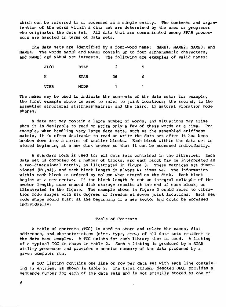
The data sets are identified by a four-word name: NAME!, NAME2, NAME3, andNAME4. The words NAME! and NAME2 contain up to four alphanumeric characters,and NAMES and NAME4 are integers. The following are examples of valid names:
JLOC BTAB 2 5
K SPAR 36 0
VIBR MODE 1 1
The names may be used to indicate the contents of the data sets; for example,the first example above is used to refer to joint locations; the second, to theassembled structural stiffness matrix; and the third, to natural vibration modeshapes.
A data set may contain a large number of words, and situations may arisewhen it is desirable to read or write only a few of these words at a time. Forexample, when handling very large data sets, such as the assembled stiffnessmatrix, it is often desirable to read or write the data set after it has beenbroken down into a series of smaller blocks. Each block within the data set isstored beginning at a new disk sector so that it can be accessed individually.
A standard form is used for all data sets contained in the libraries. Eachdata set is composed of a number of blocks, and each block may be interpreted asa two-dimensional matrix, as illustrated in figure 3. These matrices are dimen-sioned (NI,NJ), and each block length is always NI times NJ. The informationwithin each block is ordered by column when stored on the disk. Each blockbegins at a new sector. If the block length is not an integral multiple of thesector length, some unused disk storage results at the end of each block, asillustrated in the figure. The example shown in figure 3 could refer to vibra-tion mode shapes with six degrees of freedom at seven joint locations. Each newmode shape would start at the beginning of a new sector and could be accessedindividually.
Table of Contents
A table of contents (TOC) is used to store and relate the names, diskaddresses, and characteristics (size, type, etc.) of all data sets resident inthe data base complex. A TOC exists for each library that is used. A listingof a typical TOC is shown in table 2. Such a listing is produced by a SPARutility processor and provides a concise summary of the data produced by agiven computer run.
A TOC listing contains one line or row per data set with each line contain-ing 12 entries, as shown in table 2. The first column, denoted SEQ, provides asequence number for each of the data sets and is not actually stored as one of

the 12 entries. The four-word data set name (shewn as NI, N2, N3, and N4 intable 2) is given as the last four entries and is used to identify a particulardata set. A description of the first eight entries for a data set are given inthe following table (from ref. 5):
TOG item Description
RR Disk address pointer to first word of data set at beginning of a newsector; a preceding minus sign means that the data set has been"disabled" (still resident on disk but cannot be accessed)
DATE Date of insertion
TIME Time of entry into the processor which inserted the data set intothe library
ER Error code:0 no error detected during generation of the data set1 minor error2 fatal error
-1 incomplete data set
WORDS Total number of words in the data set; data sets are generally com-prised of a sequence of physical records, or "blocks"; each blockis a two-dimensional matrix dimensioned (NI ,NJ), i.e., NI rows,NJ columns; the block length is always NI*NJ
NJ See above
NI*NJ See above
TY Type code:0 integer
-1 real-2 double precision4 alphanumeric
An understanding of the information contained in a TOG is necessary forusing the data handling routines in a user program to access the data sets.Several TOC entries are used as parameters or arguments which are passed tothe routines at execution time. When TOC information is needed in centralmemory, it is stored in COMMON block CLIB, as described in appendix D.
Master Directory
A SPAR library begins at sector zero with MASTER, a 64-word array, whichis the master directory for that library. This array contains the followinginformation:

MASTER(l) Number of the first unused sector in the library (the upper endof the file)
MASTER(2) Number of TOC segments currently in the library
MASTER(3) Number of data sets per segment (presently fixed at 32)
MASTER(3+N) Sector number of beginning of TOC for Nth segment
Since MASTER is a 64-word array, the maximum number of segments that a librarymay contain is 61. The values of MASTER(I) and MASTER(2) are updated as dataare added to the library.
As indicated, each library is self-contained, with MASTER containing point-ers to TOC's for each segment and each TOC segment containing pointers to thedata sets. Utilities exist in SPAR to store complete libraries as a data set(nesting of libraries), so that an unlimited number of data sets can be storedon a single library if desired.
Any data sets to be added to the library are written at the upper end ofthe file at the relative sector number given in MASTER(l). If a data set withthe same name as the new one already exists on the library, the old one is dis-abled (indicated in the TOC by a minus sign appended to the relative sector num-ber). When master directory information is needed in central memory, it isstored in COMMON block CLIB, as described in appendix D.
DESCRIPTION OF SPAR DATA HANDLING UTILITIES
There are two basic ways of communicating with the SPAR data complex. Thefirst is to use the utility processors included in SPAR, and the second is touse the SPAR data handling routines directly to create new processors.
The first method is useful for performing general utility operations suchas entering data created by other programs into the SPAR data complex, printingdata sets, or moving data sets between libraries.
The data complex utility (DCU) provides the capability to print tables ofcontents as well as individual data sets. A COPY command is provided to trans-fer specified data sets between libraries. This capability is very useful insaving selected information between runs. The XCOPY and the XLOAD command areused to copy data sets from the direct-access libraries to sequential files andvice versa. These sequential files can then be used to interface other programswith the SPAR system or can be stored on magnetic tape for future use. Commandsare also available in DCU for disabling and enabling or changing names of datasets and for nesting and reconstituting SPAR libraries. The arithmetic utilitysystem (AUS) provides for input of user-defined data sets into the library, aswell as general matrix arithmetic operations with any of the data sets. Thismode of working with data sets in the data complex is described in the SPAR ref-erence manual (ref. 5) and provides the flexibility to use the SPAR system in"nonstandard" applications.
The second method involves embedding statements to call the data handlingroutines directly in the user program. This method is desirable for the pro-gramer who is writing new SPAR processors, modifying existing ones, or possiblyusing the data complex to handle data in a system which is totally unrelated toSPAR. An overview of available routines and the functions they perform in auser program is given in this section. Detailed descriptions of these routinesare given in appendixes A and B.
<~c
Organization of Data Handling Utilities
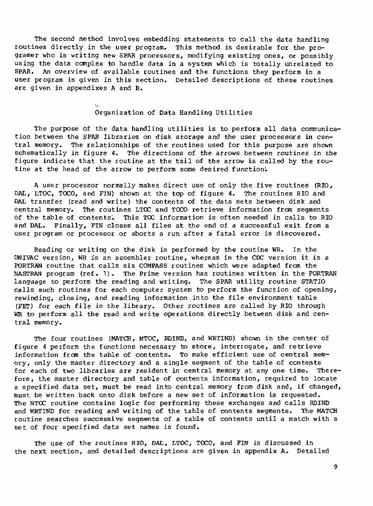
The purpose of the data handling utilities is to perform all data communica-tion between the SPAR libraries on disk storage and the user processors in cen-tral memory. The relationships of the routines used for this purpose are shownschematically in figure 4. The directions of the arrows between routines in thefigure indicate that the routine at the tail of the arrow is called by the rou-tine at the head of the arrow to perform some desired function!.
A user processor normally makes direct use of only the five routines (RIO,DAL, LTOC, TOCO, and FIN) shown at the top of figure 4. The routines RIO andDAL transfer (read and write) the contents of the data sets between disk andcentral memory. The routines LTOC and TOCO retrieve information from segmentsof the table of contents^. This TOC information is often needed in calls to RIOand DAL. Finally, FIN closes all files at the end of a successful exit from auser program or processor or aborts a run after a fatal error is discovered.
Reading or writing on the disk is performed by the routine WR. In theUNIVAC version, WR is an assembler routine, whereas in the CDC version it is aFORTRAN routine that calls six COMPASS routines which were adapted from theNASTRAN program (ref. 1). The Prime version has routines written in the FORTRANlanguage to perform the reading and writing. The SPAR utility routine STATICcalls such routines for each computer system to perform the function of opening,rewinding, closing, and reading information into the file environment table(FET) for each file in the library. Other routines are called by RIO throughWR to perform all the read and write operations directly between disk and cen-tral memory.
The four routines (MATCH, NTOC, RDIND, and WRTIND) shown in the center offigure 4 perform the functions necessary to store, interrogate, and retrieveinformation from the table of contents. To make efficient use of central mem-ory, only the master directory and a single segment of the table of contentsfor each of two libraries are resident in central memory at any one time. There-fore, the master directory and table of contents information, required to locatea specified data set, must be read into central memory from disk and, if changed,must be written back onto disk before a new set of information is requested.The NTOC routine contains logic for performing these exchanges and calls RDINDand WRTIND for reading and writing of the table of contents segments. The MATCHroutine searches successive segments of a table of contents until a match with aset of four specified data set names is found.
The use of the routines RIO, DAL, LTOC, TOCO, and FIN is discussed inthe next section, and detailed descriptions are given in appendix A. Detailed

descriptions of the other utility routines shown in figure 4 are given inappendix B.
Functions Performed by Data Handling Utilities
In this section a description is given for using RIO, DAL, LTOC, TOCO,and FIN to perform desired functions within a user program or processor. Ageneral discussion of these routines is given by user function, and the formalparameters used to call the routines are described in appendix A.
Creating data sets.- Data sets that contain only one block may be createdwith a single call to DAL. For example,
CALL DAL(1,1,KA,0,1,KADR,IERR,88,1,88,0,4HCUCU,4HCUCU,1,0)
creates a data set with the four-word name CUCU CUCU 1 0 in library 1 and writesinto it the first 88 words of the array KA. On return KADR contains the firstsector number for this data set.
If a data set contains more than one block, it may be created by a callto DAL to open the data set, followed by several calls to RIO to write out theindividual blocks of the data set. For example, to create a data set contain-ing the array TRID(5,10,7) such that the last index is the block number, thefollowing sequence of FORTRAN statements is used:
CALL DAL(NU,0,TRID,KORE,IEA,KADR,IERR,350,10,50,-!,4HTRID,4HARRY,0,7,)DO TOO 1=1,7
100 CALL RIO(NU,10,2,KADR,TRID(1 ,1,1) ,50)
The first call to DAL opens a data set called TRID ARRY 0 7 and specifiesits parameters (number of words, block size, etc.); KADR is returned with thesector number where the data set is to be written. Note that DAL is used withIOP=0 (see DAL description in appendix A for definition of IOP), so that not asingle word of the data set is actually written into storage. The seven callsto RIO transfer the seven blocks of TRID into storage.
Sometimes the number of blocks or the block size that is to be written ona data set is not known ahead of time. In this case any numbers (or zeros) maybe used for these parameters in the initial call to DAL to open the data set.Later after all the blocks of that data set have been written into storage,another call to DAL (CALL DAL(NU,-1 . . . ) ) is used to change the parameters ofthe TOC for the data set. Care should be taken to avoid calling DAL to open orwrite another data set into the same library before the first data set has beencompletely written by appropriate calls to RIO.
Reading data sets.- The first block in a data set may be read by callingDAL with IOP=11. For example, the statement
CALL DAL(1,11,KA,KORE,IEA,KADR,IERR,NWDS,NE,LB,ITYPE,4HCUCU,4HCUCU,1,0)
10
reads into central memory at beginning location KA the first block of the dataset CUCU CUCU 1 0. Additionally, the data set parameters NWDS, NE, LB, andITYPE are returned and KADR is set to be the first sector number of the dataset. If several blocks of a data set are to be read starting from the firstone, the sector number of the first block in the data set must be found andthen RIO used to read the data set block by block. This information may beobtained by using the subroutines DAL or TOCO or the function LTOC. For exam-ple, the first sector number of data set TRID ARRY 0 7 is placed in KADR byeither of the following three sequences:
(i) KADR = LTOC(NU,1,4HTRID,4HARRY,0,7)
(ii) CALL DAL(NU,10,KA,KORE,IEA,KADR,IERR,NWDS,NE,LB,ITYPE,4HTRID,4HARRY,0,7)
(iii) COMMON/TOCLIN/LINE(12)NA4(1) = 4HTRIDNA4(2) = 4HARRYNA4(3) = 0NA4(4) = 7NLINE = 0CALL TOCO(NU,NA4,1,NLINE)KADR = LINE(l)
In (i), only the desired single parameter KADR is obtained. In (ii), the otherdata set parameters (NWDS, NE, LB, and ITYPE) are also returned. The thirdsequence (iii), using TOCO, gives the most extensive information, as all 12 TOCentries are placed in COMMON/TOCLIN/LINE (1 2) .
Once the sector number for the first block is obtained, RIO may be usedto read several blocks. For example, to read 7 blocks each of 50 words intothe array TRID(5,10,7) starting at sector number KADR, the following sequenceis used:
DO TOO 1=1,7100 CALL RIO(NU,20,2,KADR,TRID(1,1,I) ,50)
Reading or modifying a part of a data set.- At times, it is desirable toread or modify only a few words of a data set rather than the entire data set.This action is particularly important when the data set is very large. It isrelatively simple to read or modify an entire block of a data set; it isslightly more complicated to read or modify part of a block.
To read or modify one block of a data set, the sector number of the firstword of the block (each block begins at the beginning of a sector) must belocated. The first step is to locate the sector number KADR where the dataset starts. This may be done by using subroutines DAL or TOCO or function LTOC.(See example in section "Reading data sets.") The second step is to calculatethe sector number of the block. If the Nth block is needed and the block sizeis LB words (LB is obtained with a procedure similar to that for obtaining KADR,as discussed in the previous section), then the sector number of the block isobtained by the FORTRAN statement
11

KSHFT = (N-1)*NSECTS(LB)+KADR
where the SPAR function NSECTS returns the number of sectors required for LBwords. A call to RIO may now be used to read or write this block.
If a block is composed of several sectors, it may be desired to read ormodify one sector of the block. For a data set beginning at sector KADR (seeprevious subsection for information on obtaining KADR) and having a block sizeof LB, the sector number KSHFT containing the Mth word of the Nth block isobtained by the FORTRAN statement
KSHFT = KADR+(N-l)*NSECTS(LB)+NSECTS(M)-1
The desired word is the Lth word in the sector, where L is obtained by
L = M-(NSECTS(M)-1)*LSECT
and the sector length LSECT resides in COMMON/CINDEX/INDEX(7),LSECT (whereLSECT = 28, 55, and 64 for UNIVAC, Prime, and CDC, respectively). Finally,RIO is used to read the sector into central memory, say into array KA, withthe following statement:
CALL RIO(NU,2,2,KSHFT,KA,LSECT)
If RIO is used to change a data set, it is recommended practice to callDAL(NU,-1,...). This call changes the date and the time in the TOC for thealtered data set and alerts the user that an alteration has been made.
Closing data files.- The last operation in each user program or processoris to close the files used by the processor. This operation is performed byusing CALL FIN(0,0). Calling this routine insures that the library files whichare generated by a processor are accessible to the subsequent processors.
Detailed descriptions of routines.- The definitions of formal parametersused in statements to call data handling routines which interface with user pro-grams are given in appendix A. Similar descriptions of routines to perform datahandling support functions and to initialize SPAR processors and read informa-tion from the input file are presented in appendixes B and C, respectively.Data (in addition to formal parameters) are also communicated between theseroutines through labeled COMMON blocks, and the contents of these blocks aredefined in appendix D.
The routines described in appendixes A to C form a self-contained softwarepackage that can be used effectively in any engineering applications program orsystem. Examples of use of this SPAR software can be found throughout the list-ings of the SPAR processors.
GUIDE FOR IMPLEMENTING SPAR DATA HANDLING UTILITIES
Many computer programs presently exist and new ones are being developedto perform a variety of engineering analysis and design tasks. One approach
12

to producing a better product using this capability is to collect all applica-ble computer programs into a software system that can be used for extensiveanalysis of that product. Such software systems require communication of dataamong the various programs, and this section describes the steps necessary toconvert existing programs so that they can use the SPAR data handling utilitiesfor this purpose. Similar logical steps could be used in designing new programswhich are intended to use this data management capability. The steps are
(1) Divide the existing program or process into the lowest level group offunctions that the user might be interested in performing. It is important thatthis division be made on a functional rather than a computer programing basis.An example of how the finite-element structural analysis procedure was dividedinto processors is given in table I1. The computer code required for each ofthese functions is referred to as a module or processor. These processorsshould be designed to operate as independent programs for UNIVAC and Prime ver-sions or as primary overlays on CDC versions. All data transfer should be han-dled through the data base complex. The zero-level overlay for the new systemwould have to be able to recognize the executive control command (IXQT on CDCand Prime and @XQT on UNIVAC) for the name of each processor and call it intocentral memory for execution.
(2) Convert the processor to use dynamic allocation of blank COMMON areain central memory for working storage for all problem-size dependent arrays.This step is not necessary but is very desirable to provide efficient use ofcentral memory. An example of dynamic storage allocation is shown in appen-dix G. Conversion of an existing program generally requires a new subroutineto set up starting addresses for arrays in blank COMMON and to call existingsubroutines using these blank COMMON addresses in the calling sequences!. Theother subroutines that are called must be altered to provide the proper respec-tive formal parameters in the subroutine statement and to provide dimensionstatements indicating that these parameters are array names. This programingtechnique can result in considerable savings of computer resources comparedwith programs containing arrays with fixed dimensions.
(3) Identify all input and output data for the program or processor. Inputdata include both user-supplied input for the processor and data sets which havebeen generated by other processors and are available for use from the data basecomplex. Output data refer to named data sets which are to be written on thedata libraries so they can be used by subsequent processors. No special consid-erations are required for printed output. Handling of user-supplied data isdiscussed in steps (6) and (7), and input and output of data sets to and fromthe data base complex are discussed in steps (4) and (5). Four-word names mustbe assigned to each of the data sets to be written onto the data base complex.
(4) Examine size characteristics of each data set to determine whetherthe set can be handled most efficiently in a single block or in multiple blocks.
(5) Insert statements into the processor to call the appropriate data han-dling routines. As mentioned in the section describing functions performed bythe data handling routines, LTOC and TOCO are often used to get size informationfor existing data sets for use in allocating blank COMMON storage. The DAL rou-
13

tine is used to handle data sets contained in a single block. A combination ofDAL and RIO is used to handle data sets with multiple blocks.
(6) Provide a call to the RSET routine (see appendix C) at the beginningof each processor. A DATA statement must be set up which specifies the name,type (integer, real, or alphanumeric), and default value of each parameter tobe used in a RESET statement for the processor. RESET parameters are used toprovide an option for the user to specify parameter values which control execu-tion of the processor, such as the library numbers or names of input and/oroutput data sets, scale factors, iteration controls, and selection of case orcondition numbers. The routine RSET causes calculation and printing of thecurrent amount of blank COMMON available in central memory (which is a functionof user-specified field length for CDC versions). This value can be comparedwith that dynamically allocated for required use by each processor.
(7) Replace all statements which read data from the input file with callsto the READER routine. This routine provides a standard method of reading allinput records in a free-field format; Use of a free-field format is particu-larly desirable when entering data from an interactive terminal and simplifiesuser documentation for a processor. Calls to the READER routine can be usedto read tables or vectors and arrays of user input data; however, an alternatemethod is recommended. The alternate method is to use the data set constructioncapability of the AUS utility of SPAR to insert the required data sets into thedata base complex before calling the processor which uses them. For example,this method is used in the present SPAR system to input data sets containingapplied-loading information.
(8) Provide a call to the FIN routine at the end of each processor to closeall files which are used!. Routine FIN also causes printing of the time on theclock measuring CPU time for the job as well as a cumulative count of timesdata were written onto disk or read into central memory during execution of aprocessor. This information provides the user some measure of performance foreach processor for the application being made.
(9) Compile and load the source of the processors to form executable files.For UNIVAC and Prime versions, each processor is a separate executable file.For CDC versions, the processors can be grouped into overlaid programs (notnecessarily a single overlaid program). Since the processors all communicatethrough the data base complex, they can be called in the desired sequence toperform a particular set of calculations.
(10) Provide user documentation for the processor. User documentation iswritten as a self-contained section for each processor. The information ineach section includes (a) the function of the processor, (b) a description ofthe RESET parameters, (c) names of input and output data sets for the processor,(d) central memory requirements (blank COMMON working area) given in terms ofvariables that are generally problem size dependent, and (e) code release infor-mation giving version of program, date coded, and originator of code.
14

CONCLUDING REMARKS
The SPAR computer software system is a collection of processors that per-form particular steps in the finite-element structural analysis procedure. Thedata generated by each processor are stored on a data base complex residing onan auxiliary storage device, and these data are then used by subsequent proces-sors. The organization of the data base complex provides significant benefitsto the user, such as reference to data by alphanumeric names and automatic"bookkeeping" procedures for the data; expedites communication of data withprograms external to SPAR; and simplifies retention of data between separatecomputer runs. The computer software associated with the data base complexprovides a general capability and can be used for management of data in pro-grams or systems other than SPAR.
This report documents the SPAR data handling utilities, which are routinesused to transfer data between the processors and the data base complex. Adetailed description of the data base complex organization is also presented.A discussion of how these SPAR data handling utilities are used in an applica-tion program to perform desired user functions is given with the steps necessaryto convert an existing program to a SPAR processor by incorporating these utili-ties. Finally, a sample SPAR processor is included to illustrate the use of thedata handling utilities. This information can be used (1) to understand moreclearly and to use more productively the existing processors in the SPAR sys-tems, (2) to develop new SPAR processors, or (3) to use the capabilities of thedata handling utilities in a system totally unrelated to SPAR.
Langley Research CenterNational Aeronautics and Space AdministrationHampton, VA 23665June 19, 1978
15

APPENDIX A
SPAR DATA HANDLING ROUTINES CALLED BY USER PROGRAM
There are primarily five data handling routines that are needed in user.programs to communicate with the data base complex. The RIO routine is thebasic input/output routine in this group and handles data sets with multipleblocks or reads or writes information within a block. Routine DAL is used toopen new data sets, to read and write data sets contained in a single block,and to modify TOC entries. Routines LTOC and TOCO are used to read informationfrom the table of contents. Routine FIN is used to close all files at the endof a processor. A description of the formal parameters used for each of theseroutines (identified as either a subroutine or a function) is given in thisappendix. In addition, the information contained in labeled COMMON blocks tocommunicate information between these routines is given in appendix C.
Subroutine RIO(NU,IWR,IOP,KSHFT,KA,L)
Subroutine RIO reads or writes L words from or into library NU.
IWR Operation code (user specified):1 wr i te2 read
10 write and return next sector number in KSHFT20 read and return next sector number in KSHFT
IOP Disk location code (user specified):1 reads or writes at the disk sector number defined by adding
KSHFT to last used sector number2 reads or writes at sector number KSHFT3 writes at first unused sector
KSHFT Sector number or shift - see IOP (user specified and returned)
KA Starting central memory address for I/O (user specified)
L Number of words to be written or read (user specified)
Subroutine DAL(NU,IOP,KA,KORE,IEA,KADR,IERR,NWDS,NE,LB,
ITYPE,NAME1,NAME2,NAME3,NAME4)
Subroutine DAL reads or writes a data set identified by the name NAME!,NAME2, NAME3, NAME4, from or into library NU. Additionally, DAL can initialize,change, or retrieve some of the parameters defining the data set. The name ofthe data set is composed of two alphanumeric words having up to four characters(NAME! and NAME2) and two integers (NAME3 and NAME4). If DAL is used to operateon an existing data set, one or more of these names may be masked (i.e., set to
16

APPENDIX A
4HMASK). Subroutine DAL would use the first active data set it encounters thatagrees with the unmasked parts of the given name.
NU Library number (user specified)
IOP Operation code (user specified):-1 change the parameters defining the data set in TOC according
to the parameters in the calling sequence and current dateand time; IERR is set if data set not found; the diskaddress pointer (KADR) is set at the first sector numberfor the data set
0 set up an entry (a line) in TOC for a new data set, and dis-able any old duplicate (same name) data sets; disk addresspointer (KADR) is set to where the data set will be written(but data set is not actually written)
1 same as IOP=0 but a data set is also written into disk at theend of the existing sets; the data set is written as oneblock, even if LB is different from NWDS; subroutine DALshould not be used to write data sets composed of more thanone block
2 same as IOP=1 except old data sets having the same name arenot disabled
10 get information from TOC without reading data set; IERR isset if data set is not found
11 same as IOP=10 but one block (LB words) of a data set is alsoread into central memory
KA Starting address in central memory of data set (user specified)
KORE Available central memory for data set (user specified and this valueis available as the first word of blank COMMON after RSET is called);if LB is larger than KORE and lOP^l, then IERR is set to -2; ifKORE=0 the check for available central memory is skipped
IEA Error return indicator (user specified):1 print error message and return2 disregard errorOtherwise print error message and abort
KADR First sector number of data set on disk (returned)
IERR Error code (user specified for write, returned for read):0 no errors
-1 data set not found-2 insufficient central memory
NWDS Number of words in data set (user specified for write, returned forread)
NE Number of columns per block (user specified for write, returned forread)
17

APPENDIX A
LB Block size in words (user specified for write, returned for read)
ITYPE Type of data (user specified for write, returned for read):0 integer
-1 real-2 double precision4 alphanumeric
NAME! Four-character alphanumeric word (user specified)
NAME2 Four-character alphanumeric word (user specified)
NAMES Integer (user specified)
NAME4 Integer (user specified)
Function LTOC(NU,J,NAME1,NAME2,NAMES,NAME4)
Function LTOC retrieves the Jth item from the TOC line for data set NAME!,NAME2, NAMES, NAME4 in library NU. If the data set is not found, then LTOC isequal to 4HXXXX on return.
NU Library number (user specified)
J Item number in TOC line; for example RR = 1, DATE = 2 (userspecified)
NAME!...NAME4 Data set name (user specified)
Subroutine TOCO(NU,NA4,IOP,NLINE)
This subroutine searches for a data set named NA4(1), NA4(2), NA4(3), NA4(4)in library NU. One or more of the entries in NA4 may be masked (i.e., set to4HMASK) and those entries are disregarded in matching NA4 against the data setnames. The search starts at line number NLINE in the table of contents.
NU Library number (user specified)
NA4 Four-word array containing the data set name (user specified)
IOP Operation code (user specified):1 TOCO retrieves the first matching data set it encounters;
the TOC entry of the data set is stored inCOMMON/TOCLIN/LINE(12) and NLINE is set to be the linenumber of the data set; if the data set is not found,then NLINE is set equal to -1
? 1 TOCO deactivates all data sets matching NA4 found afterline NLINE; on return NLINE is equal to the number of datasets that were deactivated
18

APPENDIX A
NLINE Line number in the table of contents (user specified and returned)
Subroutine FIN(NERR,NER)
Subroutine FIN is called as the last operation in each processor to closethe files used by the processor. If it is not called, these files might not beaccessible to the next processor. When FIN is called at the completion of theprocessor task, NERR and NER are equal to 0. Subroutine FIN is also called toabort the run after a fatal error is discovered. In this case NERR and NER areprinted out in format A4,I10 as a diagnostic for the error. Subroutine FINcauses printing of the time on the clock measuring CPU time for the job as wellas the cumulative count of times data were written onto disk or read into cen-tral memory during execution of a processor. FIN calls TCLOCK and DATIM forthis purpose (see appendix C), although they are not shown in figure 4 sincethey are not directly involved with data handling.
19
APPENDIX B
SPAR ROUTINES TO PERFORM DATA HANDLING SUPPORT FUNCTIONS
Several routines are used to perform support functions for the five rou-tines that are needed in user programs and were described in appendix A. Thesesupport routines are normally not called directly by a user program. However,a detailed description of these routines is included in this appendix to pro-vide a more complete definition of the operation of the SPAR data handling util-ities shown in figure 4. Such information on the more basic routines is neededwhen transferring this system to a new host computer operating system.
Function MATCH(NU)
Function MATCH returns the line number (currently between 1 and 32) from asegment of the table of contents which is resident in central memory for libraryNU. The line number corresponds to the data set name which must be passed tothe function in the last four words of COMMON/TOCLIN/LINE(12). Function MATCHsearches successive lines of successive TOC segments, starting with the firstsegment in library NU, until a match of data set names is found. If the speci-fied data set name is not found, MATCH is set to 0 on return. Function MATCHcalls RDIND to read successive segments of the table of contents.
Function NTOC(NU)
To conserve central memory, bookkeeping information for portions of theTOC for only two libraries can be resident in central memory at any one time.The NTOC routine performs the function of exchanging this bookkeeping informa-tion between disk and central memory as needed by DAL, LTOC, TOCO, and FIN.This routine returns either the value 1 or 2, which corresponds to the user-specified library number NU and reads the required information into centralmemory if it is not already there. The information which is read into centralmemory includes the master directory MASTER(64,2) and a segment of the table ofcontents IND(12,32,2), which are both contained in COMMON/CLIB/...
Subroutine RDIND(N,IBLK)
Subroutine RDIND performs the function of reading the data in the segmentof a table of contents denoted IBLK from the library corresponding to N (either1 or 2), where N is equal to NTOC(NU). These data are read into central memorystarting at IND(1,1,N)1 This subroutine also updates and writes the masterdirectory MASTER(64,N) from central memory to disk each time a new data set isadded to the library.
20

APPENDIX B
Subroutine WRTIND(N)
Subroutine WRTIND writes the information contained in the segment of thetable of contents which is in central memory and whose library corresponds toN onto the library file on disk.
Subroutine STATIC(NU,ITYPE,IASG)
Subroutine STATIC is used to cause the file with the library number NU tobe opened or closed.
ITYPE Code for opening or closing the file:=0 close the file and IASG will be returned to zero1 open a direct-access file2 open a sequential file
IASG Error code for file opening:0 an end of file was encountered while attempting to do a
check or to read the file environment of a direct-accessfile after opening it
1 a direct-access file is successfully opened
Subroutine WR(NU,KA,LE,NS,IOP ,ISTAT,NWTX)
Subroutine WR directly performs transfer of data between central memoryand disk in the UNIVAC version. For CDC and Prime versions, this subroutineserves as an intermediary between RIO and other machine-dependent routines thatperform the transfers. All data transfers are performed using an integer numberof disk sectors. The number of disk sectors required for transferring LE wordsis calculated in WRL If LE is not an integer multiple of the sector length, thelast partially filled sector is temporarily stored in COMMON/B64/L64(64) and thefilled portion of this sector is then added onto the array KA. For the CDC ver-sion, the disk address NS at which the transfer is to occur is passed to theCOMPASS subroutines in IDX(2), which is contained in COMMON/PAR.
Function NSECTS(L)
Function NSECTS returns the number of disk sectors required to containL words. The number of words per sector is given in LSECT in COMMON/CINDEX/(LSECT = 28, 55, and 64 for UNIVAC, Prime, and CDC versions, respectively).
Function LADJ(L)
Function LADJ returns the total number of words available on the disk sec-tors which are required to contain L words. The relationship between the func-tions LADJ and NSECTS is LADJ(L) = LSECT*NSECTS (L) .
21

APPENDIX B
Other Routines
A detailed description of the formal parameters in the call sequences ofthe machine-dependent COMPASS subroutines for the CDC version are not includedherein. The general function they perform is as follows:
XOPEN opens sequential and direct-access files
XREWIND rewinds files
XEVICT closes files
READX reads data from disk to central memory
WRITEX writes data from central memory to disk
WRTINX is a write-in-pi ace subroutine for replacing existing records on afile
The routines are used for both sequential and direct-access files. Theread and write operations do not require a buf fer area in the user's program.
22

APPENDIX C
ROUTINES TO INITIALIZE SPAR PROCESSORS AND READ USER INPUT
In addition to the data handling routines there are SPAR routines whichare used to perform the initialization of the processors and to read user-prepared data from the input file. The relationships among these routines areshown schematically in figure 5. Subroutine RSET is called at the beginning ofeach processor. Subsequently, RSET calls KOREFL (on CDC) or KSIZE (on UNIVAC)or uses LOG directly (on Prime) to calculate the amount of blank COMMON storagelocations available. On the UNIVAC system, RSET calls KEXP to expand the avail-able central memory as requested by the user. Routines TCLOCK, DATIM, and IA6are also called by RSET to supply the date and time entries for the table ofcontents of all data sets produced by that processor.
Subroutine READER is used throughout the processors to read all data fromthe input file. Subroutine READ actually causes a record to be read and func-tion RALPH is used in assembling alphanumeric words as the record is being inter-preted by READER.
Subroutine RSET(IL,M,IEA)
Subroutine RSET is used to read RESET statements which appear on the inputfile following the @XQT command for each processor. Subroutine RSET also causesthe input record following the last RESET statement to be read. Parameters usedin this reading process are passed to the subroutine through the array IL andinteger M, These values are defined in DATA statements in the user program.
M Number of reset parameters to be used
IL(1,I) Contains the four-character alphanumeric name of the Ith reset parame-ter (1 £ I S M)
IL(2,I) Contains the type code for the parameter:0 integer
-1 real4 alphanumeric
IL(3,I) Contains the actual value for the parameter; the default value whichis defined in the user program is replaced by the value, if any,which is read from the RESET statement which is input
IEA Error return indicator:0 program execution will terminate if an error is detected
on a RESET statement
^ 0 an error on a RESET statement is ignored
23
APPENDIX C
Subroutine KOREFL(A,KORE,KFL)(This subroutine used in CDC version only)
This COMPASS subroutine calculates the amount of central memory KOREbetween the address of A and the end of the user-specified field length KFL.KORE is calculated by the equation
KORE=KFL-(Address of A)- 1
This subroutine is called by RSET in SPAR to determine the amount of blankCOMMON which is available to be allocated for working storage.
Subroutine TCLOCK(I,CP,DCP)
Subroutine TCLOCK returns the current time from the CPU clock for a job.DCP is the amount of CPU time that has been used since the last call to thissubroutine. If I is equal to 1, DATIM is called to calculate the current dateand time which is then stored in COMMON/CIDT/IDATE,ITIME. If I is equal to 3,DCP and CP are printed.
Subroutine DATIM(IDATE,ITIME)
This subroutine returns the current date and wall clock time as alphanu-meric words in the form 77/03/17. and 11.12.05.
Function IA6(IA10)(This function used in CDC version only)
Function IA6 converts a 10-character word like 0123456789 to a 6-characterword in the form 124578. The function is used in SPAR to change a date from thealphanumeric form 77/03/17. to the integer 770317 and time from 11.12.05. to111205. These integer forms of date and time are used as entries in the tablesof contents for data libraries.
Subroutine READER
Subroutine READER interprets the information on an input record having afree-field format which follows the rules given in the SPAR Reference Manual(ref. 5). The decoded information is returned in COMMON/INREC/. (See appen-dix D for a description of the contents of this COMMON block.)
Subroutine READ(IA,IEOF)
Subroutine READ reads an 80-character record from the input fi le into an80-word array IA. The parameter IEOF is 0 for a normal read and 1 if an end-of-file is hit when attempting to read.
24
APPENDIX C
Function RALPH(IN,N)
Function RALPH assembles the N characters contained as separate words inthe array IN into a single left-adjusted word. The integer N must be equal toor less than 4.
25

APPENDIX D
CONTENTS OF LABELED COMMON BLOCKS
This appendix contains the contents of labeled COMMON blocks which areused for communication among the routines shown in figures 4 and 5. Theseblocks are presented in alphabetical order of the block name for each groupof routines.
COMMON Blocks Used by Data Handling Routines of Figure 4
(Blocks CFIN and CIDT are used by some of these routines but are explainedin the next section.) The COMMON blocks used by the routines of figure 4 aregiven below along with a description of their contents.
COMMON/B64/L64(64)
L64 Used for temporary storage of words from a disk sector that ispartially full (see discussion of subroutine WR in appendix B)
COMMON/CLIB/NSWAP,NUNS,NUN(2),NOP(2),NBLOKS(2),NWRITE(2),INCORE(2),NMAST,MASTER(64,2)INDSZ,NIND,LIND,IND(12,32,2)
This COMMON block contains information on the two segments of the TOC's fromtwo different libraries currently resident in central memory (see also section"Description of SPAR Data Handling Utilities")
NSWAP Counter that is incremented in function NTOC each time a segmentof the TOC of a library is exchanged between central memory anddisk
NUNS Fixed value of 2, indicating that the master directory and a seg-ment of TOC (containing 32 entries) from two libraries can bein central memory at the same time
NUN(I) Contains the library number which corresponds to the Ith (1 or 2)set of directory and TOC information currently in centralmemory
NOP(I) Counter which indicates the relative activity or use of the twolibraries; the library with least activity is replaced when anew one is required
NBLOKS(I) Number of segments in the table of contents for the library;it is identical with MASTER (3,1)
NWRITE(I) Set to 0 when the segment of the table of contents IND(12,32,I)is written to disk, or is set to 1 when the master directoryMASTER(64,I) is written to disk (where I = 1 or 2)
26

APPENDIX D
INCORE(I) Contains the sequence number of the segment for the table ofcontents of the library currently in central memory
NMAST Number of entries for each of the two libraries in MASTER; pres-ently fixed at 64
MASTER(64,I) Master directory for the two libraries (see the sectionentitled "Master Directory")
j->INDSZ Number of entries in a line of the table of contents; presently
fixed at 12
NIND Number of lines per segment of the table of contents; presentlyfixed at 32
LIND Total number of words in a segment of the table of contents;LIND=INDSZ*NIND, presently equal to 384
IND(12,32,I) Segment of the table of contents (see the section "Tableof Contents")
COMMON/CINDEX/INDEX(7,30),LSECT
INDEX(1,1) Not defined (I refers to Ith user-specified library number)
INDEX(2,I) Current location of the disk address pointer
INDEX(3,I) Next available (not yet used) address in library I
INDEX(4,l) Counter for the number of read statements from the library
INDEX(5,I) Counter for the number of write statements to the library
INDEX(6,I) File status indicator:-N a file has been opened and is now closed0 a file has not been openedN a file is currently open, where N is the user
library number; for direct-access files,1 S N ^ 26; for a sequential file, N = 10 000
INDEX(7,I) Order of assignment of files which are currently active;the number of entries in the NASG array
LSECT Number of words per sector on the auxiliary storage device(28 words for UNIVAC, 55 words for Prime, and 64 wordsfor CDC)
COMMON/NAMASK/MASK,LUNIT
MASK Equal to 4HMASK
27

APPENDIX D
LUNIT Equal to6HSPARL for CDC version4HSPIA for Prime version6HSPAR for UNIVAC version
CCMMON/PAK/IDX(2) ,NPAKS ,NASG (10) ,IPAK(17,10)
This COMMON block is used by subroutines WR and STATIC to communicate with theCOMPASS language I/O subroutines
IDX(l) Not defined
IDX(2) Used to pass the disk address at which a read or write operationis to occur
NPAKS Maximum number of active files allowed; presently set at 10
NASG(I) User-specified library number for the Ith active file that is cur-rently open
IPAK(17,I) 17 words comprising the file environmental tables (FET) forthe Ith active file
COMMON/TOCLIN/LINE(1 2)
LINE(I) Ith entry in a line of the TOC (see section entitled "Table ofContents")
COMMON Blocks Used by Subroutines Shown in Figure 5
The COMMON blocks used by the routines of figure 5 are given below alongwith a description of their contents.
COMMON/CFIN/IABORT,IOPRT
IABORT Flag which has a default value of zero but can be changed in aRESET record, for any processor, to a value of unity and theprocessor will not make an error abort if it encounters a seri-ous error (e.g1., if the required data sets do not exist)
IOPRT Similar to IABORT, except a value of unity causes the processorto print extra I/O information
COMMON/CFMT/KALT(10)
KALT Contains user-specified global control parameters for the proces-sors; currently, only three parameters are used
KALT(l) Contains the value specified on a FORMAT input record; this param-eter is used in different processors for different purposes(see the TAB and SA processors in SPAR)
28

APPENDIX D
KALT(2) Contains the value specified on an ONLINE input record; the valueis 0 for minimum printout, 1 for normal printout, or 2 for max-imum printout
KALT(3) Contains the value specified on an IOUT input record
COMMON/CIDT/IDATE,ITIME
IDATE Contains an integer date in the form 770317
ITIME Contains an integer time in the form 111205 (see the descriptionsof TCLOCK, DATIM, and IA6 in appendix C)
COMMON/INREC/IDATA(40),KIND(40),NAME,NOW,NA41,NA42,NRPR,ICHAR(81)
IDATA Contains up to 40 words which could be put on an 80-column inputcard, since words must be separated by blanks, commas, etc. inthe SPAR free-field input format
KIND Contains the type code for each of the words in IDATA
NAME Contains IDATA(l) if it is an alphanumeric word; otherwise itis zero
NOW Number of words used in the IDATA array
NA41 Word number in IDATA where four-character words in the commentfield start
NA42 Word number where the comment field ends
NRPR Contains the number of input records on the input card which wasread
ICHAR Contains the 80 characters from an input card with a $ inICHAR(81)
29

APPENDIX E
LISTING OF SAMPLE PROCESSOR
The sample processor contained in this appendix illustrates the use of theSPAR data handling routines. The five data handling routines (RIO, DAL, LTOC,TOCO, and FIN) described in appendix A are included in this processor as wellas the input routines (RSET and READER), which are described in appendix C.
The function of the processor is to create a library and subsequently readand print a data set containing a vector of real numbers and a data set contain-ing a matrix of integers. Comments are included in the listing, which follows,to give a detailed description of the steps performed by the processor.
PROGRAM TESTINTEGER VGOUVGOZCOMMON/ I NREC/ IDATA UO ) , KIND ( 40 ) , NAME , NO* , NAi* 1 , NA<42 , NRPR, ICHAR (61 }COMMON/TOCLIN/ LINEC12)COMMON KOREfKEVENfA(l)DIMENSION KA(1)DIMENSION CDATA(<40)DIMENSION NA«(4)DIMENSION I V ( 3 f < O f R V ( 3 f < OEQUIVALENCE CA(l)fKAU))EQUIVALENCE CIOATA ( 1 ) ,CDAT A ( 1 ) )EQUIVALENCE ( I V ( 1 , 1) , » V ( 1 , 1) )DATA NL/4/DATA IV
i/4HNLIBf Of 1, «MNHV , 0, 0*f«HNKM , Of Of 4HNCM , Of 0»/
CC TO READ RESET VALUES AND FIRST DATA CARDC
CALL RSET(IVfNLfO)NU * IV(3fl)NHONV • IV(3f2)NRQKM 9 IV(3f3)
CC TO SET UP POINTERS IN BLANK COMMONC
VOiOl • 1MG01 s VG01+NRONVVG02 • MGUI*NROMM*NCOLMMGOi a VG02+NRUNV
CC TO PUT VECTOR IN BLANK COMMON STARTING AT VG01C
DO 10 IslfNROHVJ a VGOUI-1
10 *(J; a CDATA(l)
30

APPENDIX E
CC TO PUT MATRIX IN BLANK COMMON STARTING AT MGOtC
DO 20 I"1,NCOLMK • MGOifNROWM*(I«nCALL HEADER00 20 J«l,NRO*ML « KfJ-1
20 KA(L) • IDATA(J)CC TO WHITE VECTOR ON DISKC
CALL 0AL(NU»l,A(VG01),0,l,KADR,IERR,NROWV,l,NROWV,»l,
CC TU WHITE MATRIX ON DISK IN BLOCKED FORMC
NWD8 • NRONMftNCOLMCALL OALCNU,0,A,0,1,KADR,IERH,NWOS,1,NHOWM,0,
UO JO I«1,NCOLMJ • MG01+NRONM*(I«1)
30 CALL RIO(NU,10,2»KADR,KA(J),NRQWM)C "C TO HEAD VECTOR INTO BLANK COMMON STARTING AT V602C
CALL UAL(NU,11»A(VC02),0,IEA,KADR,IERH,NW08,N6,L8,ITYPE,*<*HTE8T,«HVEC ,1,1)
ISO • VG02IEND • IGO+NRUwV-1WNITE«>,<*0) (AUJr l ' IGOt lEND)
40 F O H M A T ( 5 X , F 1 0 . 2 )CC TO USE BOTH LTOC AND TOCO TO GET INFORMATION TO READ MATRIXC
KAQH a LTOCCNU,1,«HTEST,«HMAT ,1,1)NA4(}) B 4HTESTNA4(2) * 4HMATNA4(3) * 1NA<U<4) • 1NLINE • oCALL TOCO(NU»NA«,1, NLINE)NM08 • LINE(S)N6. * LlNE(b)Lb • LINE(7)NbLKS » NWDS/LBIF(NBLKS*LB.NE(NMDS) NBLKS • NBLKStl
CC TO READ MATRIX INTO BLANK COMMON STARTING AT MG02C
DO SO I«l, NBLKSJ • MG02+LB-CI-1)
50 CALL HIO(NU,20,2,KADR,KA(J),LB)IGO i MG02IENU a IGO+NROMM*NCOLM»1MHITE(6,60) (KA(I),I«IGO,IENU)
60 FOHMAT(/5X,5I7)
31

APPENDIX F
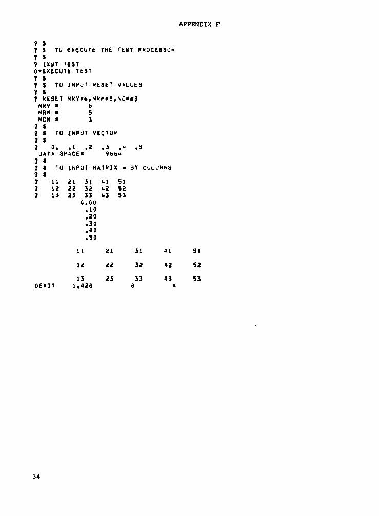
LISTING FROM INTERACTIVE EXECUTION OF SAMPLE PROCESSOR
The listing contained in this appendix is from an interactive executionof the sample processor, so that it includes both input to and output from theprocessor. The information following the operating system prompt (the "?" char-acter) is input from the user;. All other lines are output by the processor orrelated SPAR subroutines. Comments are included in the listing to describe theinput that follows each comment. These comments all begin with the $ character.
Executipn of the sample processor is initiated by the executive controlcommand, [XQT TEST. (Note the CDC and Prime versions use [XQT and the UNIVACversion uses @XQT.) RESET values which control execution of the processor arethen specified. The four RESET values which can be input to the sample proces-sor are shown in the data statement containing the IV array. (See listing ofthe processor in appendix E.)
These RESET values are defined as follows:
Name Default value Meaning
NLIB 1 Library number on which data sets will be created
NRV 0 Number of rows in the vector to be input
NRM 0 Number of rows in the matrix to be input
NCM 0 Number of columns in the matrix to be input
In the listing for the interactive execution of the sample processor, thedefault value of NLIB =1 is used and remaining reset values are specified bythe user, as shown in the listing. The values for the vector and the matrix arethen input by the user and, after being stored on and retrieved from disk, areprinted by the processor.
Next an executive control command is used to execute the SPAR data com-plex utility (DCU) processor. User commands are input to this processor, whichprints the table of contents of library 1 containing the two created data setsand also the contents of these data sets, as shown in the listing. Finally theexecutive control command, [XQT EXIT, is used to terminate the run. Output fromexecution of the sample processor is as follows:
33
APPENDIX F
77
7
TU execute rue TEST PROCESSUK77 XflT fEST0* X6CUTE TEST7
TO INPUT RESET VALUES7? RESET NRV«6,NRM«5,NC*«3NRV • 6NRM • 5NCM • 3? S7 s TO INPUT VECTOK7 $7 0. .1 .2 .3 .4 .SDATA SPACE- 966U7 *7 S TO INPUT MATRIX - BY COLUMNS7 »7 11 21 31 41 517 12 22 32 42 527 13 23 33 43 53
o.oo.10.20.30.40.50
11 21 31 4} 51
12 22 32 42 52
13 23 33 43 53OEXIT 1.426 S 4
34

APPENDIX F
77 TO CALL SPAR UTILITY PROCESSOR77 XQT OCU0* XECUTE DCU77 TO PHJNT TABLE OF CONTENTS77 TOC 1OATA SPACE" 819201TABLE OF CONTENTS,
DCU
SEO1
RH7
DATE780523
8 780523 092148
LIBRARY 1ER00
TIME092148
1 TOSPHJNT
PKINT CONTENTS OF OATA SETS
1 TEST VEC
1VEC
TEST
77770PRIN LJB/3Efl» I/IBLOCK i TEST0 I* 1 !• 2J« 1 0. .10000E+00
OABOVfc PRODUCED FROM Lib 1TOC« 7 780523 092148TEST VEC
7 PRINT i TEST MAT0PRIN
WORDS615
NJ1M*NJ
6
OATA SETNl N2
TEST VECTEST MAT
NAMEN311
VEC1
I«,20000EfOO
1
I* 4.30000E+00
> 1
.40000E+00!• 6.SOOOOE+
1 1•1
1BLOCK0J«1BLOCK0J"1BLOCK0J«
1
1
EQB I/TEST
I* 111
TEST1» 1
12TEST
I* 113
2MAT
MAT
MAT
TEST MAT1
OABOVfc PRODUCED FROM LIB 1
221
222
223
13
31133213
33
I»
H41
a42
a43
551
552
5S3
I«
TOC»TEST
7 IXBOEXIT
MATEXIT
1.518
8 780523 0921481
IS
35
APPENDIX G
DYNAMIC STORAGE ALLOCATION
Dynamic storage allocation is a programing technique to stack all problem-size dependent arrays into the blank COMMON area of central memory in an effi-cient manner. The amount of blank COMMON that is allocated for an array is theminimum needed to accommodate the array size for a given problem. This tech-nique eliminates most dimension statements with fixed-size arrays.
The SPAR system uses dynamic storage allocation, since the size of most ofthe arrays that are used depends on the size (number of joints and elements) ofthe finite-element model being analyzed. This technique is not unique to SPAR;that is, many other programs or systems have used it. However, since this tech-nique is very desirable for use with the SPAR data handling routines, a descrip-tion of the basic principles of dynamic allocation is included herein forcompleteness.
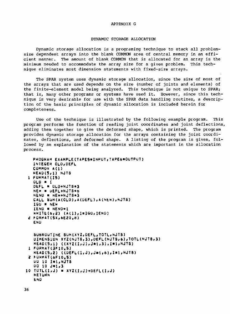
Use of the technique is illustrated by the following example program. Thisprogram performs the function of reading joint coordinates and joint deflections,adding them together to give the deformed shape, which is printed. The programprovides dynamic storage allocation for the arrays containing the joint coordi-nates, deflections, and deformed shape. A listing of the program is given, fol-lowed by an explanation of the statements which are important in the allocationprocess.
PKOGKAM EXAMPLE(TAPES"INPUT,TAPE6"OUTPUT)INTEGER OLO,DEFLCOMMON A(l)HEADC5,1) NJTS
1 FOKMATU5)OLD > 1DEFL • QLD+NJTS*3NE« • L>EFLtNJTS*6NEND • NEw*NJT8*3CALL SUM(A(OLO),A(DEFL),A(NtW),NjTS)ICO • NENIEND « NEND-1*KlU(b,2) (A(l),I»IGu,IEND)
i. FORMATC5X,6E20.»)END
SUbROUTINE SUM (XYZ,DEFL»TOTL»NJTS)DIMENSION XYZ(NJT8,3),DEFL(NJTS,6),TOTL(NJTS,J)HEAD(5,}) (CXYZ(I,J),J«1,3),I«1,NJTS)
1 FOKMATUF10.5)HEAD (5,2) (CDEFK1,J),J»1,6),I«1,NJTS)
2 FOKMATC6F10.5)DO 10 fil,NJTSUO 10 J«l,3
10 TUTLCI»J) • XYZ(IfJ)tDEFL(I»J)HETUNNEND
36

APPENDIX G
The blank COMMON area is designated as array A. On CDC systems, A onlyneeds to be dimensioned at A(l), since it actually extends to the end of thefield length for the job. For UNIVAC programs, A is typically dimensioned toaccommodate a small or medium-size problem. Core expanding routines (such asKEXP) may be used for large problems. Alternatively, the main program may berecompiled with a larger value in the COMMON statements when a large problemis solved. The problem-size-dependent parameter (NJTS), which indicates thenumber of joints to be considered, is read from the input file. In SPAR, suchparameters usually come from the table of contents. The pointers OLD, DEFL,and NEW are calculated as the starting addresses in array A for the array con-taining joint locations, deflections, and deformed shape, respectively. Thetotal amount of blank COMMON required is given by NEND. These array startingaddresses are passed to the subroutine SUM, which actually performs the addi-tion. In subroutine SUM, these arrays have names which reflect the informationthey contain. The dimension statement is required for names which are arraysin the parameter list of SUM.
Conversion of an existing program to provide dynamic storage allocationgenerally requires a subroutine to set up the starting addresses of arrays andto call other subroutines using these addresses in the calling sequences. Thecalling sequences often get quite long if many arrays with different names areused. For subroutines performing the calculations, the proper respective formalparameters in the subroutine statement must be provided, and dimension state-ments indicating that these parameters are array names must be added.
37

REFERENCES
1. Butler, Thomas G.; and Michel, Douglas: NASTRAN - A Summary of the Functionsand Capabilities of the NASA Structural Analysis Computer System. NASASP-260, 1971.
2. Miller, Ralph E., Jr.: Structures Technology and the Impact of Computers.Integrated Design and Analysis of Aerospace Structures, R. F. Hartung, edi,American Soc. Mech. Eng., c.1975, pp. 57-70.
3. Sobieszczanski, Jaroslaw: Building a Computer-Aided Design Capability Usinga Standard Time Share Operating System. Integrated Design and Analysis ofAerospace Structures, R. F. Hartung, edl, American Soc. Mech. Eng:., c.1975,pp. 93-112.
4; Giles, Gary L.: Computer-Aided Methods for Analysis and Synthesis of Super-sonic Cruise Aircraft Structures. Proceedings of the SCAR Conference -Part 2, NASA CP-001 , [1977], pp. 637-657'.
5. Whetstone, W. D.: SPAR Structural Analysis System Reference Manual - SystemLevel II. Volume I - Program Execution. NASA CR-145096-1, 1977.
6. Storaasli, Olaf 0.; and Foster, Edwin P.: Cost-Effective Use of MinicomputersTo Solve Structural Problems. AIAA Paper No. 78-484, Apr. 1978.
7. Whetstone, W. D.: Computer Analysis of Large Linear Frames. J. Struct. Div.,American Soc. Civil Eng., vol. 95, no. STll, Nov. 1969, pp. 2401-2417.
8« Whetstone, William D.; and Jones, Charles D.: Vibrational Characteristicsof Linear Space Frames. J'. Struct. Div., American Soc; Civil Eng., vol; 95,no. ST10, Oct. 1969, pp. 2077-2091.
38
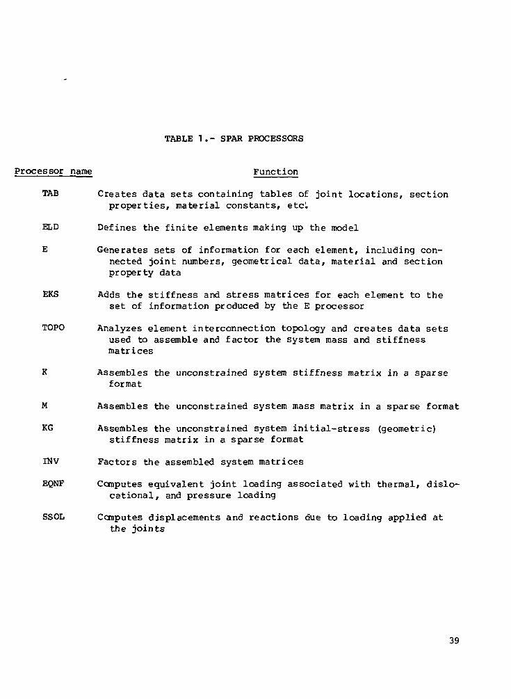
TABLE 1.- SPAR PROCESSORS
Processor name Function
TAB Creates data sets containing tables of joint locations, sectionproperties, material constants, etc!.
ELD Defines the finite elements making up the model
E Generates sets of information for each element, including con-nected joint numbers, geometrical data, material and sectionproperty data
EKS Adds the stiffness and stress matrices for each element to theset of information produced by the E processor
TOPO Analyzes element interconnection topology and creates data setsused to assemble and factor the system mass and stiffnessmatrices
K Assembles the unconstrained system stiffness matrix in a sparseformat
M Assembles the unconstrained system mass matrix in a sparse format
KG Assembles the unconstrained system initial-stress (geometric)stiffness matrix in a sparse format
INV Factors the assembled system matrices
EQNF Computes equivalent joint loading associated with thermal, dislo-cational, and pressure loading
SSOL Computes displacements and reactions due to loading applied atthe joints
39

TABLE 1.- Concluded
Processor name
GSF
PSF
EIG
DR
SYN
STRP
AUS
ECU
VPRT
PLTA
PLTB
Function
Generates element stresses and internal loads
Prints the information generated by the GSF processor
Solves linear vibration and bifurcation buckling eigenproblems
Performs a dynamic response analysis
Produces mass and stiffness matrices for systems comprised ofinterconnected substructures
Computes eigenvalues and eigenvectors of substructured systems
Performs an array of matrix arithmetic functions and is used inconstruction, editing, and modification of data sets
Performs an array of data management functions including displayof table of contents, data transfer between libraries, chang-ing data set names, printing data sets, and transferring databetween libraries and sequential files
Performs editing and printing of data sets which are in the formof vectors on the data libraries
Produces data sets containing plot specifications
Generates the graphical displays which are specified by the PLTAprocessor
40

TABLE 2.- TABLE OF CONTENTS FOR SPAR DATA LIBRARY
SEQ123a5678910111213141516171819202122232425262726293031323334353637383940
RR7•a
-12131415162632333773129130131132133134U5136137138139140164108<J122362372362623605061466148715112176296029643008
DATE761022761022761022761022761022761022761022761022761022761022761022761022761022761022761022761022761022761022761022761022761022761022761022761022761022761022761022761022761022761022761022761022761022761022761022761022761022761022761022761022
TIMfc081237081237061237081237081237081237081237081237081237061237081237061241081241081241061241061241081241081241081241081241081241061241081241081244061244081244061244061244081244081244061245081245061254081248081246081302061323061333081333081345
ER0000000000000000000000000000000000000000
T DATA SET NAMErtORDS
18250123010487502502525022503136
2151257111111
1500150015001500
11
15006272896062720
201500
4256050176IbOO1500
10760
NJ1
2501214
250250
1250250196
11
1211111111
250250250250
1i
25025025019620250250250250250196
Nl*NJ18
250123010467502502525022508962
151257111111
1500150015001500
11
1500896179232020
150022403584150015005555
Y Nl0 JDF10 JREF1 ALTR4 TEXT1 MATC1 ALTR1 JLOC0 JREF1 SA0 CON1 QJJT0 OEF0 GO0 BUTo NELZ0 KE0 NS3 ELTS0 ELTS0 ELTS0 ELTS0 ELTS0 ELTS
APPLAPPLUNITAPPLTOT
1 CONV1 DISK0 KMAP0 AMAP4 E430 OIK
-1 DEM1 K1 INV
-1 STAT-1 STAT•1 STRS
N28TA88TABBTABBTABBTABBTABBTABBTABBTAB
BTAB£43E43E43BTAB
NAMELTYPNNODISCTNELSLE3FORCPORCVECMOT!FORCAUSINC
EFILE43DIAUSPARKOI8PNEAC£43
N312222222212
1111111000000001215511
10871675
11110
361
1002
100
N4864i245613019444
11000000001111111
172644000111
41

CO £>& U
^ <J Q
|rt HH PH
CQ^ W Q
0 >,CQ ^ &jCO o ^ IZ
8s b 5U H i vJ'O <D S W
ftS
<^ oft c ftC/3 0) O W
0 EH
.s(1)g CQ Q
^ H W
t
Q)•— i
£
-t-»
1
H < PQK H H
> ft ft
ft
1* HCO CO
SFjj Q^
W W
co O ft
§ *
CO
W H
rt(1)ct0)
so
"tob£•S
1
CQ0)
•f-t
S•fH-M
I— 1-o2
*rt
«
m ^ Q ^H fH r_T EH kx IT;
< C
• • • w • • •
I I I
^ <; * s...Q ...
""* PI r iy § o» c?
^ w * x
otM
K
ii_^
H
CO
H
^^ •<ubC
X rt0) ?H
gto^H
rri >rH
•° Srt
•TH • • • £5
^ HOH M
PQ ^^
13 Q
w^ • • • *^
,-H
p- co^^^V* ^
!3 Q
PQJK
2CO
ii
<J, _1
K
ft
n
«-P*
eQ)jjCO
CO
co•H
CO
1-1IDCmtf
m
o
§•HJJ10N
C(0o>MO
1
l-l301
42

CMn(Oa
co
WHgOu
wKPHOPKH
K<K«
>>
°
cu
0)CO
•" rt X
.s=|8sH co50
O> -tt«*Hg 1°» S S
-§
O
-
<U
AoRtV
t-lo
rt o4^ <>HS *}•o g'S °h »0 .£>
-Q -M
S 22 0)
S5 K
b£>.3T3CaCOVf-,FHOu
li^g o
a^S«liCO r—I
CDrt P
0)
co
• rH
%!H0)
o
COCD
•s
13
(1)JJ
OO
•O
10
(1)MD4JO
I
•CNI
43
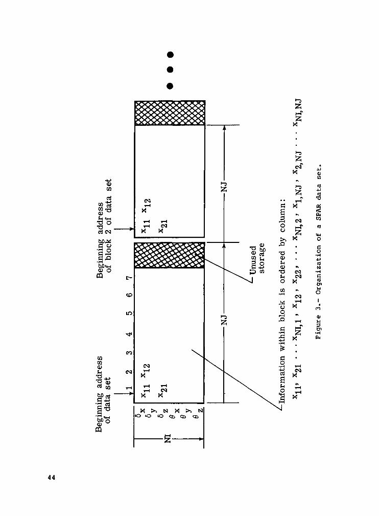
COCQ<U
^ ®aj ou
OS+->Cj
1*0a*.
PQ
CO
CQ
CKIi—I
X
i-l CKIX X
\CM
X
X >> N X >> Nto «D o ct ij <
i=lO
•-3S5H-Tiz;
oo
CM
I 1
73a>SHO ^
73 CM!H CS1o xCQ
O W
5 .
•§ £
CQ
01CO
(0-Um•a
10(0
14-1o
o4JtoN•HCtoUoIn
0)
3O>•Hfa
44

Input/output routines(machine dependent)
UNIVACWR
CDCWRREADXWRITEXWRTINX
PrimeWRPRWFIL
File opening and closing(machine dependent)
UNIVACASG
CDCXOPENXREWINDXEVICT
PrimeSEARCH
SPAR libraries on auxiliary storage
Figure 4.- Relationships of SPAR data handling routines.
45

^HOCQCQ(UUO
a
VCQp
HwK
(U
tu ^*
• S&^ «JT3
3 MO)0 c dT3 '" '01 ^1X°S3
££
PHXW
SI
Uou
t?^^OJ T3
.§ w•0"^ a?
o rt 0)rv 0,-S^ -t-> J3
rt o
0
SP
^<i— i<jQ
U
U
JgH^S
2
•<J nj
0)g
£
H
ci§J,
t-lU-l
0
10eowC•H
•O
•o
o(0(0<u8gj
CO 3a,0) CN -H
m
•HC
KMQ
WK
W w^K » e
^,001
•a<utoa100)C
Ia>1-1o
46

1
4
7
9
12
Report No 2 Government Accession NoNASA TM-78701
Title and SubtitleSPAR DATA HANDLING UTILITIES
Author(s)
Gary L. Giles and Raphael T. Haftka
Performing Organization Name and AddressNASA Langley Research CenterHampton, VA 23665
Sponsoring Agency Name and AddressNational Aeronautics and Space AdministrationWashington, DC 20546
3
5
6
8
10
11
13
14
Recipient's Catalog No
Report DateSeptember 1978Performing Organization Code
Performing Organization Report
L-12106
Work Unit No743-01-03-05
Contract or Grant No
No
Type of Report and Period CoveredTechnical Memorandum
Sponsoring Agency Code
15 Supplementary Notes
Raphael T. Haftka: Illinois Institute of Technology, Chicago, Illinois.
16 Abstract
The SPAR computer software system is a collection of processors that perform partic-ular steps in the finite-element structural analysis procedure. The data generatedby each processor are stored on a data base complex residing on an auxiliary storagedevice, and these data are then used by subsequent processors. The computer soft-ware associated with the data base complex provides a general capability and can beused for management of data in programs or systems other than SPAR.
This report documents the SPAR data handling utilities, which are routines used totransfer data between the processors and the data base complex. A detailed descrip-tion of the data base complex organization is also presented. A discussion of howthese SPAR data handling utilities are used in an application program to performdesired user functions is given with the steps necessary to convert an existingprogram to a SPAR processor by incorporating these utilities. Finally, a sampleSPAR processor is included to illustrate the use of the data handling utilities.
17 Key Words (Suggested by Author(s))
Data handlingData baseData managementData transfer
18 Distribution Statement
Unclassified - Unlimited
Subject Category 61
19 Security Classif (of this report)
Unclassified
20 Security Classif (of this page)
Unclassified
21 No of Pages
46
22 Price*
$4.50
* For sale by the National Technical Information Service, Springfield Virginia 22161 NASA-Langley 1978


National AeronauticSndSpace Administration
Washington, D.C.20546Official BusinessPenalty for Private Use, $300
0-CLASS Postage and Fees PaidNational Aeronautics andSpace AdministrationNASA-451
US. MAIL
082178 S908Q1HODOUGLAS COBP
_PHlIiICATIpBS GBOJP PB 15246-A- -- -
r\JASA POSTMASTER- If Undeliverable (Section 158Postal Manual) Do Not Return