spatially controlled surface deposition of a versatile ... · microscopia de infravermelho e afm...
TRANSCRIPT
Sérgio Miguel Rodrigues Fernandes
Bachelor of Science in Chemical and Biochemical Engineering
Spatially Controlled Surface Deposition of a
Versatile ATRP Macroinitiator by Inkjet Printing
Dissertation to obtain the master’s degree in Chemical and
Biochemical Engineering
Advisor: Dr Joost Duvigneau, Visiting Assistant Professor, University of Twente.
Co-advisor: M. Sc.Marco Cirelli, PhD student, University of Twente.
Jury:
President: Prof. Mário Eusébio
Questioner(s): Dra. Teresa Casemiro
Vowel(s): Prof.a Dra. Maria Miranda Reis
October of 2018

II
Blank page
III
Sérgio Miguel Rodrigues Fernandes
Bachelor of Science in Chemical and Biochemical Engineering
Spatially Controlled Surface Deposition of a
Versatile ATRP Macroinitiator by Inkjet Printing
Dissertation to obtain the master’s degree in Chemical and
Biochemical Engineering
Advisor: Dr Joost Duvigneau, Visiting Assistant Professor, University of Twente.
Co-advisor: M. Sc.Marco Cirelli, PhD student, University of Twente.
Jury:
President: Prof. Mário Eusébio
Questioner(s): Dra. Teresa Casemiro
Vowel(s): Prof.a Dra. Maria Miranda Reis
October of 2018

IV
Blank page

V
Copyright
Spatially Controlled Surface Deposition of a Versatile ATRP Macroinitiator by Inkjet
Printing
Copyright © 2018 – Sérgio Miguel Rodrigues Fernandes and Faculty of Science and Technology
– New University of Lisbon.
All rights reserved
The Faculty of Science and Technology has the right, perpetually and without geographical limits,
to file and publish this dissertation thought printed copies reproduced in paper or in digital format,
or any other means known or to be invented, and to disseminate it through scientific repositories
and to allow them to be copied and distributed for non-commercial educational or research
purposes, provided that the author and publisher are given credit.

VI
Blank page

VII
Acknowledgements
First and for most, I would like to thank the MTP group for allowing me to do the
dissertation within the group, in particular, G. Julius Vancso who is a person that I hold the utmost
respect and admiration and also Joost Duvigneau that reminded me of a strong-willed that has
clear purposes in mind as all good supervisors should have. Being my daily supervisor, I would
like to thank Marco Cirelli, which inspired me with his long and intense working habits without
never holding his smile throughout the day. I will always remember the traditional 10h30pm
meetings and the memorable expressions such as “I will be right back, 30s” or the “tché”
everytime I needed further explanation but more importantly, the “work hard, play hard” motto
that sums pretty well the work hard but enjoy life personality that you have. I also wanted to thank
everyone that was part of the MTP family during my time there for all the support and for the way
you made me feel like a true member of the family. Particularly, I want to thank Clemens for all
the help that he gave me and for showing me how I will be in the future, and Paola, my Erasmus
“mom”, that was always there for me from day one to my final day. I won't forget the songs that
we sang, our dinners, the late nights at the lab, the pool games or even the day I broke my and
you went to buy one super early in the morning.
I want to thank my parents for always being there for me all these years and for allowing
me to fulfil every experience that I craved to do during my university journey. I'm grateful that
you were the rock I needed to hold to now fly for other experiences. To the rest of my family,
thank you as well for accompanying me in this journey, and for all the words of encouragement
when I was abroad.
Thank you as well to the many friends that I made throughout my journey as a university
student and that without them this path would have lost its heart and its essence. Of those many
friends, Kets and Catarina deserve a special mention for visiting me during my time in Twente
and Gonçalo for the frequent conversations that we had as we both participated in the Erasmus
program.
Last but not least, to all my friends outside the university and my friends from Nave de
Haver that were with me all these years and that supported me in this final chapter of this last five
amazing years. From family and friends that I made in the pass to the new connections that I made
in the present, I’m truly happy to be surrounded by people that always wanted the best for me.

VIII
Blank page
IX
Resumo
Funcionalização de superfícies de ouro para possíveis aplicações em revestimentos com
uma técnica de deposição bem definida de um passo, nomeadamente, impressora de jato de tinta,
foi alcançado de acordo com a seguinte metodologia:
Primeiramente, o macroiniciador de polimerização radical de transferência de átomos, i.e
poli[metacrilato de 2-(2-bromoisobutiriloxy) etilo] (PBIEM) foi sintetizado através de
transferência de fragmentação de adição reversível (RAFT) do metacrilato de 2-hidroxietil
(HEMA) e a sua subsequente funcionalização com brometo de α-bromoisobutirilo (BIBB), ver
esquema 5-1 e esquema 5-2. Espectroscopia de infravermelho por transformada de Fourier com
reflectancia total atenuada (ATR FT-IR) e espectroscopia de ressonância magnética nuclear de
protões (1H-NMR) confirmaram a sucesso síntese de poli(HEMA), PHEMA, por RAFT, ver
figura 5-2. A partir de 1H-NMR, o peso molecular por número (Mn) de um precursor preparado
foi determinado como sendo aproximadamente 23 kDa (6th PHEMA). Esta funcionalização de
PHEMA com BIBB foi também confirmado por ATR FT-IR e 1H-NMR, ver figura 5-4 e figura
5-5.
Segundo, o PBIEM preparado foi depositado numa superfície de ouro através de
impressão de jato de tinta. Diversas tintas foram produzidas sendo que a PBIEM-B (derivada da
6th PHEMA) 10% (p/p) em N, N-dimetilformamida (DMF) rendeu camadas de enxerto mais
densas. Medições de angulo de contacto de água (CA) e microscopia de infravermelho foram
usadas para provar o enxerto do macroiniciador de ATRP em ouro. As imagens de altura do passo
da microscopia de forca atómica (AFM) forneceram a espessura e rugosidade de camadas
iniciadoras em superfícies de ouro. A espessura da camada de PBIEM obtida e de
aproximadamente ~17 nm.
Por fim, as cadeias laterais constituídas por poli(N-isopropilacrilamida) (PNIPAM) foram
sintetizadas via “grafting from” por ATRP para produzir estruturas do tipo escova de garrafa.
Microscopia de infravermelho e AFM foram utilizadas para confirmar a fabricação bem-sucedida
de polímeros escova de garrafa. Conversões ate 15% foram obtidos.
Palavras chave: Impressora de jato de tinta, polimerização RAFT, ATRP, escova de
garrafa.

X
Blank Page

XI
Abstract
Functionalization of gold surfaces for possible coating applications with a one-step
pattern deposition technique in inkjet printing was achieved by the following methodology:
First, the atom transfer radical polymerization (ATRP) macroinitiator, i.e. poly[2-(2-
bromoisobutyryloxy) ethyl methacrylate] (PBIEM) was synthesised by the reversible-addition
fragmentation transfer (RAFT) polymerization of 2-hydroxyethyl methacrylate (HEMA) and its
subsequent functionalization with α-bromoisobutyryl bromide (BIBB), see scheme 5-1 and 5-2.
Attenuated total reflectance Fourier transform infrared spectroscopy (ATR FT-IR) and proton
nuclear magnetic resonance spectroscopy (1H-NMR) confirmed the successful synthesis of
poly(HEMA) (PHEMA) by RAFT, see figure 5-2. From 1H NMR spectra, the number-average
molecular weight (Mn) of one prepared precursor was determined to be approximately 23 kDa (6th
PHEMA). The functionalization of PHEMA with BIBB was confirmed by ATR FT-IR and 1H-
NMR spectroscopy as well, see figure 5-4 and figure 5-5.
Secondly, the prepared PBIEM was deposited on gold surface by inkjet printing. Several
inks were produced being that the PBIEM (derived from 6th PHEMA 23kDa) 10% (w/w) solution
in N, N-Dimethylformamide (DMF) yielded more dense grafting layers. Water contact angle
measurements (CA), optical microscopy and infrared microscopy were used to prove the grafting
of the ATRP-macroinitiator on gold. The atomic force microscopy (AFM) step height images
provided the thickness and roughness and of deposit initiator layers on gold surfaces. The obtained
PBIEM layer thickness is approximately ~17 nm.
Last, poly(N-isopropylacrylamide) (PNIPAM) side chains were synthesised via grafting
from by ATRP to produce bottlebrush type structures. Infrared microscopy and AFM were used
to confirm the successful fabrication of bottlebrush polymers. Conversions up to 15% were
obtained.
Keywords: Inkjet printing, ATRP macroinitiator, RAFT polymerization, ATRP,
bottlebrush.

XII
Blank page

XIII
Table of Contents .................................................................................................................................................................... 1
1.1 Introduction ........................................................................................................................................... 1
1.2 Theoretical introduction ........................................................................................................................ 2
1.2.1 Controlled Radical Polymerization (CRP) ........................................................................................ 2
1.2.2 RAFT polymerization ....................................................................................................................... 4
1.2.3 ATR polymerization ......................................................................................................................... 6
1.2.4 Inkjet Printing ................................................................................................................................... 7
State of Art ........................................................................................................................................ 9
2.1 ATRP Macroinitiator ............................................................................................................................ 9
Bottlebrush polymer synthesis ............................................................................................................ 10
Exemplar though-out applications ....................................................................................................... 12
2.3.1 Antifouling surfaces ........................................................................................................................ 12
2.3.2 Stimuli-responsive surfaces............................................................................................................. 12
Intruments Theory ........................................................................................................................... 13
3.1 NMR ................................................................................................................................................... 13
3.2 ATR FT-IR and ATR FT-IR microscopy ............................................................................................ 15
3.3 AFM .................................................................................................................................................... 17
Experimental methods ..................................................................................................................... 19
4.1 Materials ............................................................................................................................................. 19
4.2 Molecular Characterization ................................................................................................................. 20
4.3 Equipment configuration ..................................................................................................................... 20
4.3.1 Rheometer ....................................................................................................................................... 20
4.3.2 Inkjet Printing ................................................................................................................................. 20
4.3.3 Spin coating .................................................................................................................................... 21
4.3.4 CA ................................................................................................................................................... 21
4.3.5 AFM ................................................................................................................................................ 21
4.4 Fabrication method .............................................................................................................................. 21
4.4.1 RAFT Polymerization of HEMA .................................................................................................... 21
4.4.2 Preparation of PBIEM ..................................................................................................................... 22
Results and discussion..................................................................................................................... 23
5.1 RAFT Polymerization of HEMA ........................................................................................................ 23
5.2 Preparation of PBIEM ......................................................................................................................... 26
5.3 Inkjet Printing ..................................................................................................................................... 29
Bottlebrush application ................................................................................................................... 37
6.1 Introduction ......................................................................................................................................... 37
6.2 Preparation of bottlebrush ................................................................................................................... 38
6.3 Results and discussion ......................................................................................................................... 39
Conclusion and recommendation .................................................................................................... 43
References ....................................................................................................................................... 45
Appendix................................................................................................................................................................... 49

XIV
Blank Page

XV
Table of Figures Figure 1-1 Comparison between RAFT, ATRP and NMP in the areas related to the synthesis of low molecular weight
(LMW), end functional polymers (End Funct), block copolymers (Blocks), range of polymerizable monomers (Mon
Range), synthesis of various hybrid materials (Hybrids), environmental issues (Env) and polymerization in aqueous
media (Water)……………………………………………………………………………………………………………3
Figure 1-2 SciFinder results on the legend topics…………………………………………..…………………………..4
Figure 1-3 Schematic representation of continuous (A) and drop-on-demand inkjet printing (B)……………………..7
Figure 1-4 Representation of DOD inkjet printing mechanisms: Thermal (left side) and piezoelectric (right side)…….8
Figure 2-1 AFM images of molecular bottlebrushes as presented in the article: (a) PBIEM-g-P(nBA), (b) PBIEM-g-
PSt, and (c) PBIEM-g-PDEGA. All scale bars have 400 nm length…………………………………………………….11
Figure 3-1 Three classes of nuclei spin………………....…….…………………………….………………………….13
Figure 3-2 Precessional range of motion for a spin 1
2 nuclei under a magnetic field…………........................................14
Figure 3-3 Representation of the inside of an NMR machine………………………………..…………………………14
Figure 3-4 Potential energy of a diatomic molecule as a function of the atom’s separation with quantized vibration
quantum numbers displayed……………………………………………………………………………………………15
Figure 3-5 ATR module work principle………………………………………………………......................................16
Figure 3-6 Schematic representation of AFM procedure………………………………………………………………17
Figure 3-7 AFM tapping mode mechanism……………………………………………………………………………18
Figure 5-1 RAFT polymerization linear kinetic plots of HEMA………………………………………………………24
Figure 5-2 NMR spectra of CPAD (a), HEMA (b), PHEMA (c)……………………………………………………….25
Figure 5-3 ATR FT-IR spectra of 6th PHEMA with highlighted characteristic peaks………………………………….26
Figure 5-4 NMR of a) PBIEM-A, and b) HEMA in CDCl3. Two dashed lines exhibit the shift of the methylene protons
after BIBB coupling……………………………………………………………………………………………………28
Figure 5-5 ATR FT-IR of a) PBIEM-A and b) PHEMA. Typical PBIEM peak is showcased in
2)……………………………………………………………………………………………….....................................28
Figure 5-6 Graphic representation of some viscosity percentual increase combinations: PBIEM-A 0.5% in DMF (blue
line) and in acetone (red line) (bottom figure), PBIEM-A DMF 10% (blue line) and 0.5 % (red line) (centre figure),
10% DMF PBIEM-B (blue line) and PBIEM-A (red line) (top figure)………………..……………………………......31
Figure 5-7 Drop formation of PBIEM-A 10% in DMF (a), and PBIEM-A 0.5% in acetone (b)………………………..32
Figure 5-8 PBIEM-A 0.5% in acetone (left side) PBIEM-A 10% in DMF (right side)………………………………...32
Figure 5-9 Pattern arrays of PBIEM-A 0.5% in acetone (left side) and PBIEM-A 10% in DMF (right
side)…………………….……………………………………………………...……………………………………….33
Figure 5-10 Optical microscope images of PBIEM-B 10% in DMFdeposit ink droplets before (left side) and after
washing (right side). On the left, a typical dewetting of the ink and the right visible scratches caused during the handling
and the washing of the samples is shown……………………………………………………………………………….33
Figure 5-11 Patterned ink drops constituted of PBIEM-B 10% in DMF……………………..………………………...34
Figure 5-12 ATR FT-IR microscope spectra of PBIEM-B 10% in DMF and the molecular mapping imaging. Each dot
colours gives a different spectrum with the same colour………..……………………………………………………....35
Figure 6-1 Bottlebrush search results using the web of science……………………………………………………..…37
Figure 6-2 ATR FT-IR spectra of a) PBIEM-g-PNIPAM bottlebrush and b) PBIEM-A 10% in DMF………………...41

XVI
Blank Page

XVII
Table of Tables Table 5-1 Characterization of PHEMA produced…………………………………………………………………......24
Table 5-2 PBIEMs synthesised from PHEMA……………………………………………..…………………………27
Table 5-3 Different ink characterization and ATRP macroinitiator layer height……………………………………..30
Table 5-4 Variable denomination for the ATRP macroinitiator, solvent and composition…………………………...30
Table 5-5 Viscosity percentual increase dependency………….……………………………………………………...30
Table 6-1 ATRP of NIPAM from the ATRP macroinitiator characterization…………….…….................................40

XVIII
Blank page

XIX
Table of Schemes Scheme 1-1 RAFT polymerization mechanism……………………………………………………………………..…..5
Scheme 1-2 ATR polymerization overall mechanism…………………………………………......................................7
Scheme 5-1 RAFT polymerization of HEMA using CPAD as CTA agent…………………….…………………...…..23
Scheme 5-2 Esterification reaction of PHEMA with BIBB………………..………………………….…………..……27
.Scheme 5-3 Defined deposition of ATRP macroinitiator ink by inkjet printing…………………………..……..…….29
Scheme 6-1 Inkjet printing of ATRP macroinitiator (left side) with subsequent bottlebrush synthesis via grafting
from…………………………………………………………………………………………………………………….38
Scheme 6-2 Bottlebrush side chain synthesis by ATRP of NIPAM………….………………………………………...39

XX
Blank page
XXI
Symbols and Abbreviations
µ magnetic momentum
ν vibration energy level
η refractive index
ϴ angle
µCP microcontact printing
1H-NMR Proton nuclear magnetic Resonance
AFM atomic force microscopy
AIBN 2,2’-azobis-2-methylpropionitrile
ATR FT-IR Attenuated total reflectance Fourier transform infrared spectroscopy
ATRP atom transfer radical polymerization
nBA butyl acrylate
BIBB α-bromoisobutyryl bromide
iBnA isobornyl acrylate
CDCl3 chloroform-d
CPAD 4 cyano-4-(phenyl-carbonothioylthio) pentanoic acid
CRP controlled radical polymerization
CTA chain transfer agent
DEE diethyl ether
DMF N, N-Dimethylformamide
DMSO-d6 dimethyl sulfoxide
DOD drop-on-demand
DPn degree of polymerization
Fbg Fibrinogen
FRP free radical polymerization
HEMA 2-hydroxyethyl methacrylate
HEMA-TMS 2-(trimethylsilyloxy)ethyl methacrylate
Mn molecular weight by number
MMA methyl methacrylate
Mw molecular weight by weight
NIPAM N-isopropylacrylamide
NMP nitroxide-mediated polymerization
OEGMA oligo(ethylene glycol) methyl ether methacrylate

XXII
PBIEM poly[2-(2-bromoisobutyryloxy) ethyl methacrylate]
PDEGA poly[(di-ethylene glycol)ethyl ether acrylate]
PDI polydispersity index
PGMA poly(glycidyl methacrylate)
PHEMA poly(2-hydroxyethyl methacrylate)
pLED polymeric light-emitting diode
P(nBA) poly(n-butyl acrylate)
PMDETA N,N,N’,N’’,N’’-Pentamethyldiethylenetriamine
PMEO2MA poly(2-(2-methoxyehtoxy) ethyl methacrylate)
PMMA poly(methyl methacrylate)
PRE persistant radical effect
PSt poly(styrene)
RAFT reversible-addition fragmentation transfer
THF tetrahydrofruran
VA-044 2,2’-Azobis[2-(2-imidazolin-2-yl) propane] dihydrochloride
1
1.1 Introduction
Inkjet printing of polymer-based inks is an attractive non-contact patterning technique
used for many applications due to its ability to precisely deposit small droplets of ink in well-
defined patterns on various substrates providing enhanced surface properties, e.g., multicolour
polymeric light-emitting diode (pLED) displays and polymer electronics.(1, 2) In this project, we
aim to functionalize gold surfaces with polymer brush patterns by i) grafting an ATRP
macroinitiator with inkjet printing and ii) the subsequent growth of polymer brushes in the
nanometre scale to be used in coating applications. Our approach will allow us to combine surface
templating techniques and polymer brush synthesis to obtain surface properties on demand using
a versatile fabrication technique to design patterned polymer brushes on the nanometre scale,
bypassing the use of masters and stamps as in other common patterning techniques such as
photolithography and microcontact printing (µCP).(3)
ATRP macroinitiators represent the future of coating technology as they enable the
formation of complex architectural structures in bottlebrush type polymers films (molecules that
are a subcategory of polymer brushes) that are very interesting since they may exhibit similar
surface properties characteristic of polymer brush films, as said by Li et al. that reported the first
study on surface properties of bottlebrush polymer thin films.(4) These films are currently used
in the preparation of antifouling surfaces,(5-7) stimuli-responsive surfaces,(8, 9) By using
bottlebrush polymers instead of brush polymers, higher grafting density surfaces can be achieved
and also a higher efficiency towards a targeted application of choice due to specific homo or
copolymer side chain configuration. Controlled radical polymerization techniques are critical in
designing well-defined macromolecules as they provide control over molecular weight and
dispersity. Of all these techniques, RAFT polymerization was chosen for the preparation of ATRP
macroinitiators because is tolerant to most functional groups and contains a protected thiol,
2
typically dithioester, which is a direct pathway, to the assembly or immobilization of graft layers
onto gold surfaces.(10)
For templating techniques, both photolithography(11) and µCP(12) (also known as soft
lithography) have been used to pattern surfaces however, inkjet printing potential is immense
even for areas that this technique has not been used before as described by Berend-Jan de Gans
and Ulrich S. Schubert.(13) Inkjet printing is very attracting technique because it’s completely
digital thus changing the printing design has little further cost impact.(14) Other advantages of
inkjet printing include tunability of the ink formulation, the overall flexibility of the technology,
easy reproducibility (possibility of automatization) and the possibility of depositing very small
amounts of material.(1)
1.2 Theoretical introduction
1.2.1 Controlled Radical Polymerization (CRP)
Due to its simplicity, free radical polymerization (FRP) has been widely adopted in many
industrial and laboratory scale polymerization processes since its maturity in the 1950s and
1960s.(15) In the last four decades, however, research efforts have been shifted to unveil new
techniques that allowed the production of macromolecules with controlled structures not
achievable in FRP mechanisms. It was with the discovery of living anionic polymerization by
Michael Szwarc in 1956 that made the pathway for major developments in other polymer
synthetic areas that allow the production of well-defined polymers with precise molecular
architectures.(16) The new techniques based on CRP, because of its inherent radical
intermediaries they possess similar limitations as in FRP, namely chemo-, regio-, stereo-
selectivities and unavoidable radical termination.(16) However, in contrast to FRP, where all
chains terminate, only a fraction of active chains between 1 and 10% terminate in CRP. The
remaining dormant chains are capable of reactivation, functionalization and chain extension to
form other structures such as block copolymers.(17) As it’s the case in designing complex
structures to produce macromolecules with defined molecular weight and very narrow
polydispersity it is critical that all chains grow simultaneously via nearly instantaneous initiation
and that chain termination reactions are minimized. This concept derives from living
polymerization that by definition is a chain growth process without chain breaking reactions such
as transfer or termination.(18, 19) Polymerizations that combines fast initiation and an absence of
termination reactions have the potential to obtain well defined macromolecular structures. So
often this CRP is called living radical polymerization, however, it is important to note that due to
3
the inherent nature of radical reactions, particularly coupling or disproportion, it’s impossible to
have a polymerization reaction completely absence of termination reactions and so it is only
possible to develop polymerization conditions that exhibit living characteristics.
There are three main mechanisms that have been used to achieve controlled radical
polymerization. The first mechanism is the reversible recombination of growing radicals with
scavenging radicals namely nitroxide-mediated polymerization (NMP) first described by
Solomon and Rizzardo.(20) (21) The first example of this mechanism is the thermal
polymerization of controlled styrene chains with a stable free radical TEMPO as described by
Georges et al. in 1993.(22) Currently the scope of NMP has greatly expanded over the years with
better control of a wide variety of monomers.(23) The second mechanism is the reversible
termination of growing radicals as it is found in ATRP that are trapped in transition metal
complexes. Metal such Li(24), Mo(25), Re(26), Fe(27, 28), Ru(29), Ni(30) and Cu(31) are proven
to successfully mediate ATRP reactions.(16) The third mechanism is based on a degenerative
exchanging process involving reversible chain transfer as in RAFT. High molecular conversions
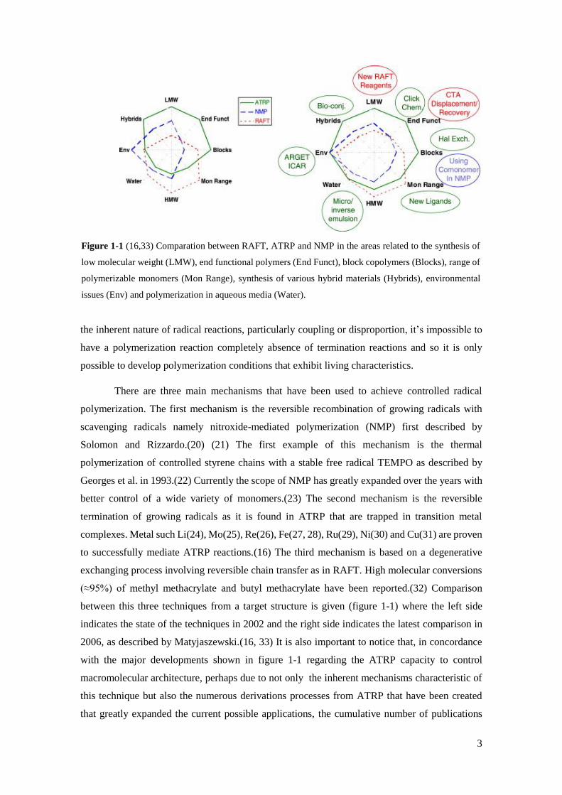
(≈95%) of methyl methacrylate and butyl methacrylate have been reported.(32) Comparison
between this three techniques from a target structure is given (figure 1-1) where the left side
indicates the state of the techniques in 2002 and the right side indicates the latest comparison in
2006, as described by Matyjaszewski.(16, 33) It is also important to notice that, in concordance
with the major developments shown in figure 1-1 regarding the ATRP capacity to control
macromolecular architecture, perhaps due to not only the inherent mechanisms characteristic of
this technique but also the numerous derivations processes from ATRP that have been created
that greatly expanded the current possible applications, the cumulative number of publications
Figure 1-1 (16,33) Comparation between RAFT, ATRP and NMP in the areas related to the synthesis of
low molecular weight (LMW), end functional polymers (End Funct), block copolymers (Blocks), range of
polymerizable monomers (Mon Range), synthesis of various hybrid materials (Hybrids), environmental
issues (Env) and polymerization in aqueous media (Water).
4
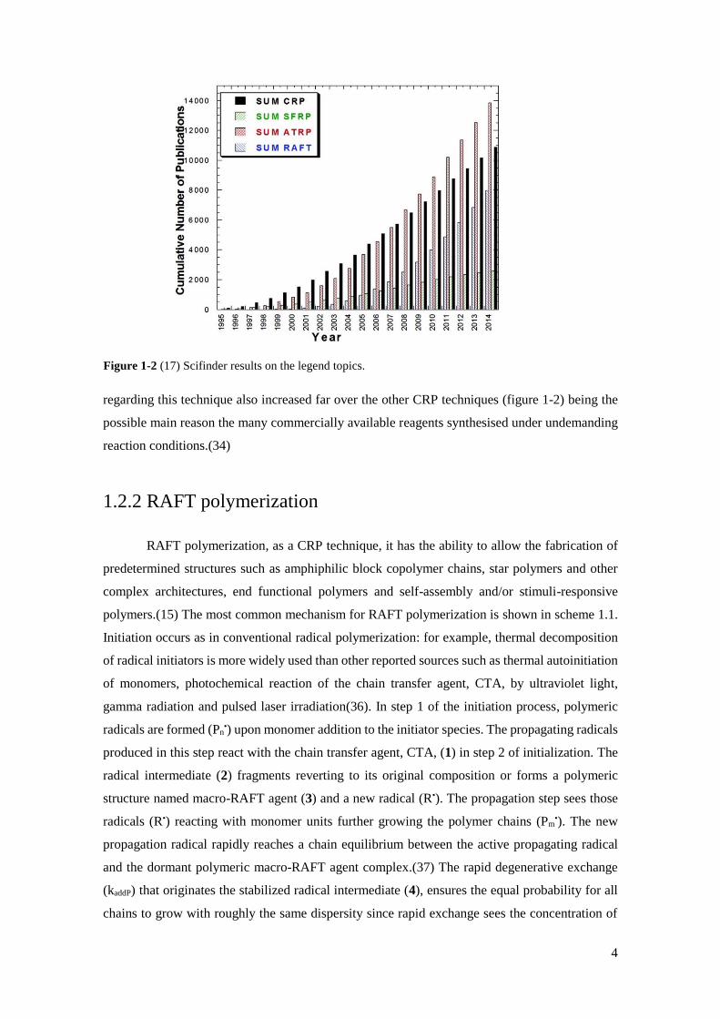
regarding this technique also increased far over the other CRP techniques (figure 1-2) being the
possible main reason the many commercially available reagents synthesised under undemanding
reaction conditions.(34)
1.2.2 RAFT polymerization
RAFT polymerization, as a CRP technique, it has the ability to allow the fabrication of
predetermined structures such as amphiphilic block copolymer chains, star polymers and other
complex architectures, end functional polymers and self-assembly and/or stimuli-responsive
polymers.(15) The most common mechanism for RAFT polymerization is shown in scheme 1.1.
Initiation occurs as in conventional radical polymerization: for example, thermal decomposition
of radical initiators is more widely used than other reported sources such as thermal autoinitiation
of monomers, photochemical reaction of the chain transfer agent, CTA, by ultraviolet light,
gamma radiation and pulsed laser irradiation(36). In step 1 of the initiation process, polymeric
radicals are formed (Pn•) upon monomer addition to the initiator species. The propagating radicals
produced in this step react with the chain transfer agent, CTA, (1) in step 2 of initialization. The
radical intermediate (2) fragments reverting to its original composition or forms a polymeric
structure named macro-RAFT agent (3) and a new radical (R•). The propagation step sees those
radicals (R•) reacting with monomer units further growing the polymer chains (Pm•). The new
propagation radical rapidly reaches a chain equilibrium between the active propagating radical
and the dormant polymeric macro-RAFT agent complex.(37) The rapid degenerative exchange
(kaddP) that originates the stabilized radical intermediate (4), ensures the equal probability for all
chains to grow with roughly the same dispersity since rapid exchange sees the concentration of
Figure 1-2 (17) Scifinder results on the legend topics.
5
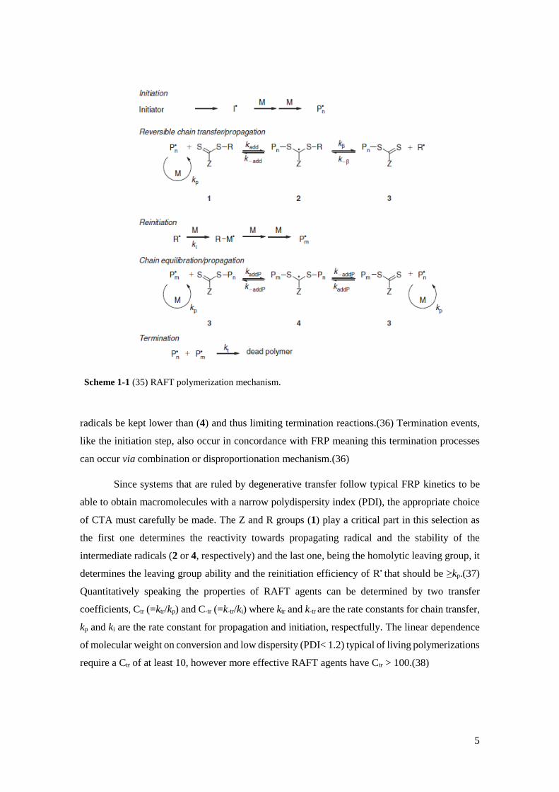
radicals be kept lower than (4) and thus limiting termination reactions.(36) Termination events,
like the initiation step, also occur in concordance with FRP meaning this termination processes
can occur via combination or disproportionation mechanism.(36)
Since systems that are ruled by degenerative transfer follow typical FRP kinetics to be
able to obtain macromolecules with a narrow polydispersity index (PDI), the appropriate choice
of CTA must carefully be made. The Z and R groups (1) play a critical part in this selection as
the first one determines the reactivity towards propagating radical and the stability of the
intermediate radicals (2 or 4, respectively) and the last one, being the homolytic leaving group, it
determines the leaving group ability and the reinitiation efficiency of R• that should be ≥kp.(37)
Quantitatively speaking the properties of RAFT agents can be determined by two transfer
coefficients, Ctr (=ktr/kp) and C-tr (=k-tr/ki) where ktr and k-tr are the rate constants for chain transfer,
kp and ki are the rate constant for propagation and initiation, respectfully. The linear dependence
of molecular weight on conversion and low dispersity (PDI< 1.2) typical of living polymerizations
require a Ctr of at least 10, however more effective RAFT agents have Ctr > 100.(38)
Scheme 1-1 (35) RAFT polymerization mechanism.
6
1.2.3 ATR polymerization
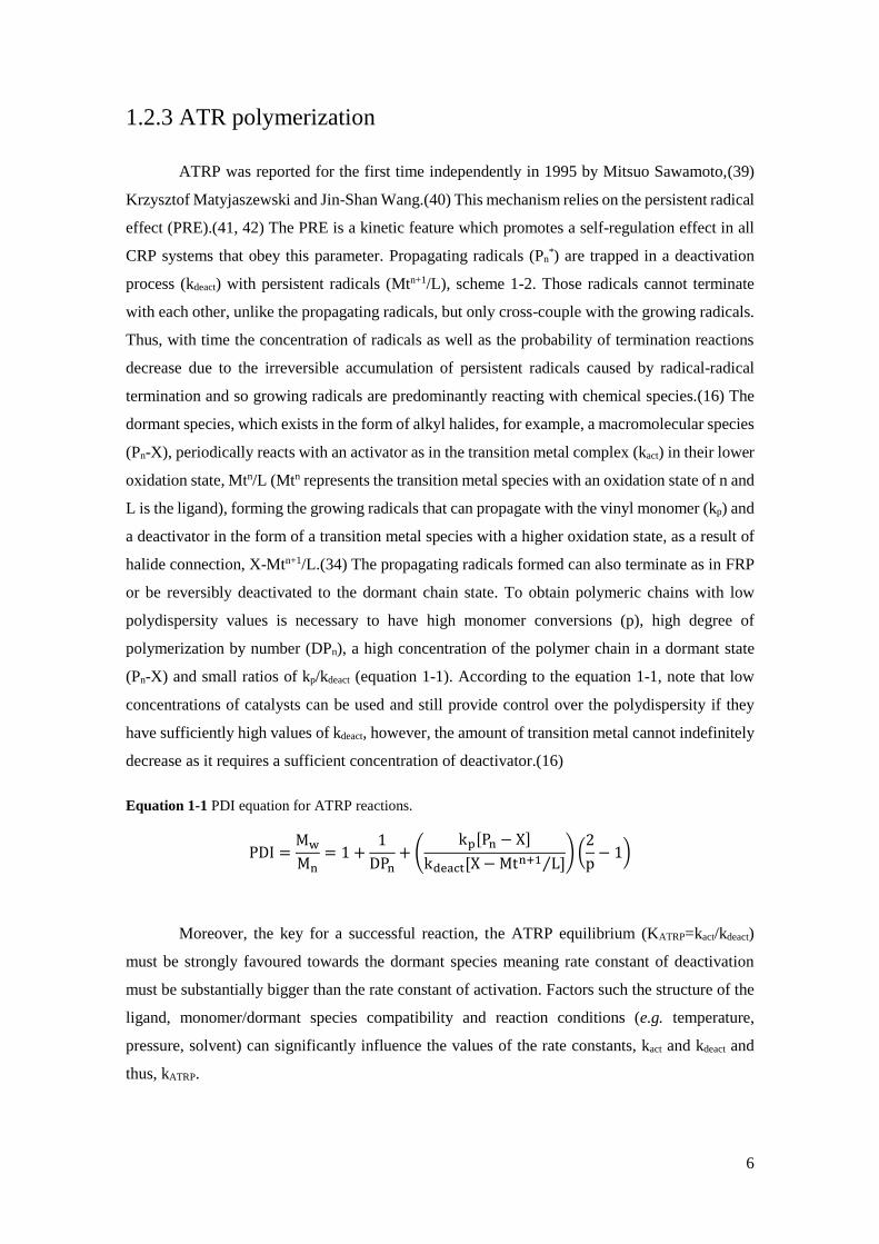
ATRP was reported for the first time independently in 1995 by Mitsuo Sawamoto,(39)
Krzysztof Matyjaszewski and Jin-Shan Wang.(40) This mechanism relies on the persistent radical
effect (PRE).(41, 42) The PRE is a kinetic feature which promotes a self-regulation effect in all
CRP systems that obey this parameter. Propagating radicals (Pn*) are trapped in a deactivation
process (kdeact) with persistent radicals (Mtn+1/L), scheme 1-2. Those radicals cannot terminate
with each other, unlike the propagating radicals, but only cross-couple with the growing radicals.
Thus, with time the concentration of radicals as well as the probability of termination reactions
decrease due to the irreversible accumulation of persistent radicals caused by radical-radical
termination and so growing radicals are predominantly reacting with chemical species.(16) The
dormant species, which exists in the form of alkyl halides, for example, a macromolecular species
(Pn-X), periodically reacts with an activator as in the transition metal complex (kact) in their lower
oxidation state, Mtn/L (Mtn represents the transition metal species with an oxidation state of n and
L is the ligand), forming the growing radicals that can propagate with the vinyl monomer (kp) and
a deactivator in the form of a transition metal species with a higher oxidation state, as a result of
halide connection, X-Mtn+1/L.(34) The propagating radicals formed can also terminate as in FRP
or be reversibly deactivated to the dormant chain state. To obtain polymeric chains with low
polydispersity values is necessary to have high monomer conversions (p), high degree of
polymerization by number (DPn), a high concentration of the polymer chain in a dormant state
(Pn-X) and small ratios of kp/kdeact (equation 1-1). According to the equation 1-1, note that low
concentrations of catalysts can be used and still provide control over the polydispersity if they
have sufficiently high values of kdeact, however, the amount of transition metal cannot indefinitely
decrease as it requires a sufficient concentration of deactivator.(16)
Equation 1-1 PDI equation for ATRP reactions.
Moreover, the key for a successful reaction, the ATRP equilibrium (KATRP=kact/kdeact)
must be strongly favoured towards the dormant species meaning rate constant of deactivation
must be substantially bigger than the rate constant of activation. Factors such the structure of the
ligand, monomer/dormant species compatibility and reaction conditions (e.g. temperature,
pressure, solvent) can significantly influence the values of the rate constants, kact and kdeact and
thus, kATRP.
PDI =Mw
Mn= 1 +
1
DPn+ (
kp[Pn − X]
kdeact[X − Mtn+1 L]⁄) (
2
p− 1)

7
1.2.4 Inkjet Printing
In order to functionalize surfaces, the appropriate deposition technique has to take into
account the targeted final application. Solvent-based techniques, such as spin-coating, dip-coating
and inkjet printing can be used to prepare bottlebrush thin film layers however this last type of
modifying surfaces have not been reported until Li et al. study.(4) Inkjet printing is a complex
technique capable to deposit a variety of inks with different properties and thus requires the
appropriate care for successful printing deposition.
There are two modes to deposit polymers based inks: continuous or drop-on-demand
(DOD) (Figure 1-3). In continuous mode, the ink is pumped through a nozzle forming a
continuous stream of sized droplets. The generated droplets are selectively charged via signals
from the printer by being subjected to an electrostatic field. The charged drops are then deflected
in a deflection field, which determines where the drop lands.(44) Depending on the system used,
the charged droplets can be printed onto the matrix or collected into a recirculation system to be
later reused. Continuous mode can print at high speeds, the nozzle is not easily clogged and has
the ability to use inks based on volatile solvents allowing rapid drying adhesion. Disadvantages
to this mode include low print resolution, the use of inks that are capable of being charged, high
investment cost as the printer has a drop selection section and a recycling unit followed by high
maintenance costs.(45) On drop-on-demand mode, a pressure pulse is created to eject ink droplets
Scheme 1-2 (43) ATR polymerization overall mechanism.
Figure 1-3 (44) Schematic representation of continuous (A) and drop-on-demand inkjet printing (B).

8
through a nozzle. DOD inkjet printers main deposition technologies are either thermally or
piezoelectrically.(46) Thermal inkjet printers (Figure 1-4 left side) rely on rapidly heating up the
ink present in the ink chamber, with the use of a resistor, to temperatures high enough to vaporize
the ink. This instantly pushes the ink droplet out through the nozzle until all the heat stored in the
ink is used, then the bubble collapses and refills the chamber.(47) Piezoelectric inkjet printers
(figure 1-4 right side) materials deform when submitted to an electric impulse and it’s through
this mechanism that the ink is ejected out of the nozzle. Additionally, because this types of printers
are not regulated by heating processes they accept a wider range of inks and they possess print
heads that last longer in comparison with thermal print heads.(45)
There are currently four main types of inks used: phase-change, solvent-based, water-
based and UV curable.(44) Within the direction of this work, the inks formulated insert themselves
in the solvent-based inks, more precisely additives. A major factor for successful printing relies
on the ink rheological properties, particularly the viscosity and the surface tension. The viscosity
should be low, typically below 20 cP, as higher values have the potential danger of viscously
dissipating too much kinetic energy preventing droplet ejection.(1) The spheroidal shape of the
liquid drop is controlled by the surface tension and its behaviour can be theoretically predicted
with a physical constant named Weber number, with fluids with high Weber values, are more
likely to present non-spheroidal shapes. Considering all the factors for successful printing
mentioned above, a commonly used parameter to indicate the capacity for good printability is the
Z parameter [the inverse of the Ohnesorge number (Oh)], where values between 1 and 10 are
expected to generate stable drop formation.(45)
Besides the rheology properties of the ink, to ensure define printability, ink formulation
must also be compatible with wettability to ensure that the ink and the substrate reach a phase of
equilibrium between themselves and the environment which is translated in the minimum Gibbs
energy state that corresponds to the most stable state named apparent contact angle.(44)
Figure 1-4 (44) Representation of DOD inkjet printing mechanisms: Thermal (left side) and piezoelectric
(right side).
9
State of Art
2.1 ATRP Macroinitiator
ATRP macroinitiators are polymers that are functionalized with an initiating group along
the polymer backbone(48) As their name suggests, these types of macromolecules are used in
ATRP systems which is a subgroup of CRP techniques as described in subchapter 1.2.1. ATRP
initiator and macroinitiators consist of alkyl halides structures and both are a critical part of ATRP
reactions as they enable the formation of well-defined polymers. Examples of complex structures
obtained with ATRP macroinitiators are represented below:
Matyjaszewski et al.(49) synthesized hybrid materials composed of inorganic
poly(siloxanes) macroinitiators. ABA Triblock copolymers obtained from difunctional
poly(dimethylsiloxane) with benzyl chloride and 2-bromoisobutyryloxy (BIBB) coupled
initiators were used to polymerize a variety list of monomers, namely styrene, isobornyl acrylate
and n-butyl acrylate (nBA) for the first initiator and methyl methacrylate and 2-
(trimethylsilyloxy)ethyl methacrylate (HEMA-TMS) for the second initiator. They discovered
that with higher molecular weight macroinitiator significant decreases in polydispersities were
observed.
Miura et al.(50) synthesised an AB20-type heteroarm star polymer consisting of
poly(styrene) (PSt) arm and 20-arms of poly(methyl methacrylate) PMMA or poly(tBA). The
ATRP macroinitiator was obtained with the following steps: NMP of styrene using mono-6-[4-
1’-(2”,2”,6”,6”-tetramethyl-1”-piperidinyloxyethyl)benzamido]-b-cyclodextrinperacetate named
as 1) to have PSt end-functionalized with the β-CyD unit, prepolymer as they call it (2); After
deacetylation of the prepolymer, the ATRP macroinitiator is formed (3) and the complex structure
prepared was obtained after reacting with 20 (2-bromoisobutyrol)s.
Cheng at al.(51) designed a norbornenyl-functional ATRP initiator by combining an exo-
norbornenyl functionality and α-bromoisobutyrate with a -CH2O(CH2)10 spacer. Novel

10
nanostructures were not synthesised and were in progress since the main focus of the article was
the preparation of new α- norbornenyl macromonomers by ATRP.
Liu et al.(52) studied the relationship between the amount of initiator anchored to the
surface and the rate of the brush layer grafted. An anchoring polymer layer consisted of
poly(glycidyl methacrylate) (PGMA) was deposited by dip-coating in a silicon substrate and the
attachment of the bromoacetic acid (BAA) was made to an unannealed as well as a preannealed
PGMA layer, observing that preannealed film originated smooth and uniform surface
morphology. PSt brushes were synthesised and they concluded that the increase in the surface
density of initiating moieties led to the increase in the grafting rate, however, a limit concentration
where the increase of initiator layers had no effect on the grafted layer was observed.
More recently, Cabane et al.(53) attempting to bring new functionalities into wood they
reported the synthesis of functional lignocellulosic materials with novel properties not have been
reported before. (Picea abies) wood samples were coupled with BIBB yielding a solid ATRP
macroinitiator denoted as W-Br. In situ polymerizations of styrene, NIPAM were performed
within the bulk wood structure.
Bottlebrush polymer synthesis
Targeting more the last concept of this work, final application bottlebrush structures
obtained with ATRP macroinitiators are given: Beers et al.(54) prepared brush copolymers of
homopolymer side chains that consisted of PSt and P(nBA). Two different approaches were used
to prepare ATRP macroinitiators for brush copolymer synthesis: In the first approach, FRP was
utilized to polymerize 2-(2-bromopropionyloxy) ethyl acrylate using 2,2’-azobis-(2-
methylpropionitrile) (AIBN); in the second approach trimethylsilyl protected HEMA-TMS was
polymerized via ATRP and subsequently esterified with BIBB in the presence of a catalytic
amount of tetrabutylammonium fluoride.
Janata et al.(48) fabricated multifunctional ATRP macroinitiators starting with low
molecular weight PSt and poly(4-methyl styrene). For the first macromolecule, three-step
functionalization procedure was performed to synthesise the ATRP macroinitiator: Friedel-Craft
acylation with acetyl chloride; reduction of carbonyls to secondary hydroxy with lithium
aluminium hydride; esterification with 2-bromopropionyl bromide or BIBB. For the latter
polymer, direct esterification using N-Bromosuccinimide as a brominating agent under AIBN and
dry carbon tetrachloride conditions were used.
Neugebauer et al.(55) in attempted to understand the grafting density of brush molecules
with different side chain lengths, they prepared a series of cylindrical brushes of PMMA and
11
poly(nBA) via grafting from. These molecules were prepared with a multifunctional
macroinitiator, PBIEM developed by ATRP of HEMA-TMS. By analysing the side chains
detached using solvolysis, they observed with PMMA side chain using copper(I)
chloride/copper(II) chloride/4,4′-Dinonyl-2,2′-dipyridyl catalyst system, a grafting efficiency cap
at approximately 50%. They concluded that the low grafting density was due to the 2-
bromoisobutyrate initiating moieties being non-ideal for the ATRP of methacrylates.
Venkatesh et al.(56) utilized the combination of RAFT and ATRP to synthesise polymer
brushes using grafting from or a combination of grafting through and grafting from. PBIEM and
poly[BIEM-co-poly(ethylene glycol) methyl ether methacrylate] grafted copolymers based ATRP
macroinitiators were used to form brushes consisting of both homopolymer side chains of methyl
methacrylate, and statistical copolymer side chains of MA and 1-octene.
Fleet et al.(57) reported the synthesis of novel glycopolymer brushes of 6-O-MMAGIc
methyl methacryloyl-α-D-glucoside, using sequential RAFT-mediated polymerization of
homopolymer PBIEM and copolymers P(BIEM-co-MMA), P(MMA-block-BIEM), poly(4-
vinylbenzyl chloride-alt-maleic anhydride) backbones, followed by ATRP of these
macroinitiators.
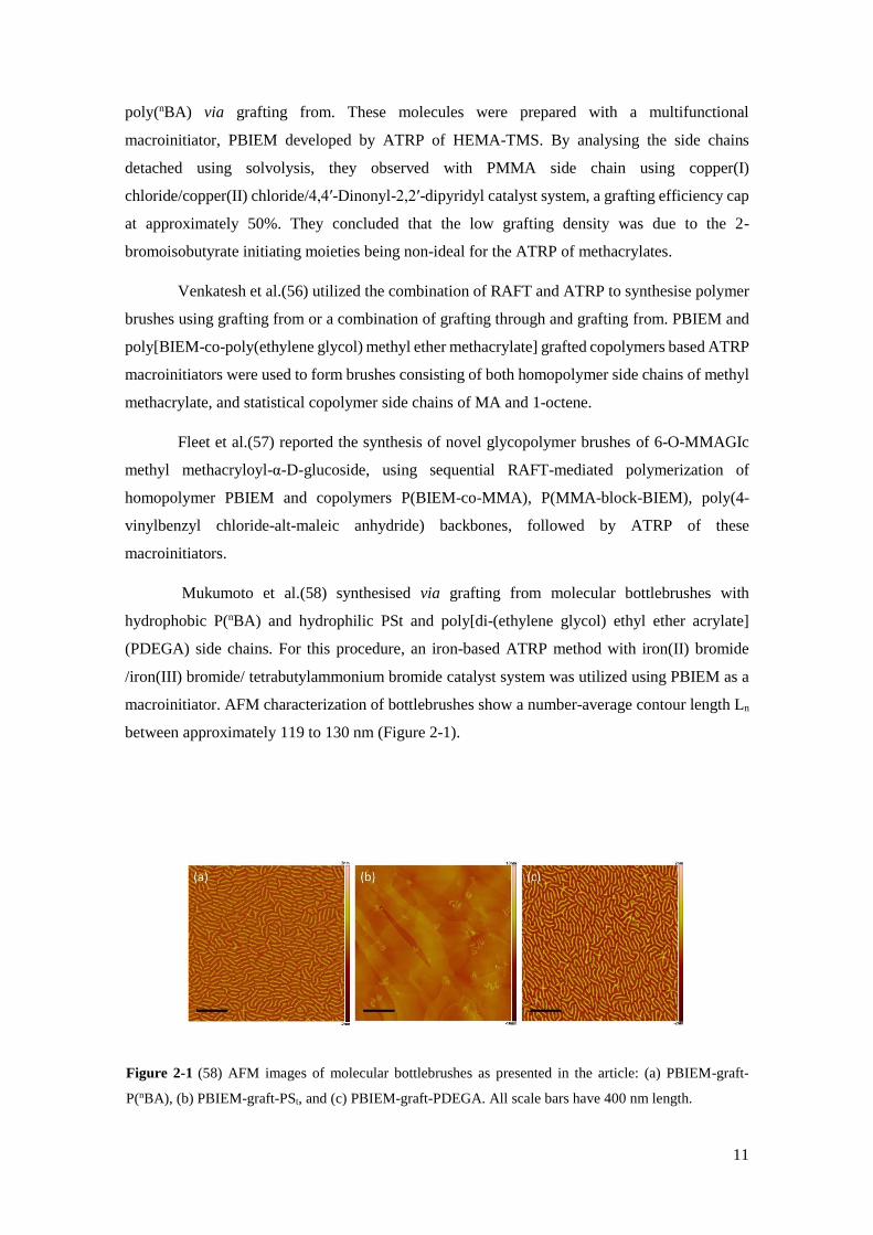
Mukumoto et al.(58) synthesised via grafting from molecular bottlebrushes with
hydrophobic P(nBA) and hydrophilic PSt and poly[di-(ethylene glycol) ethyl ether acrylate]
(PDEGA) side chains. For this procedure, an iron-based ATRP method with iron(II) bromide
/iron(III) bromide/ tetrabutylammonium bromide catalyst system was utilized using PBIEM as a
macroinitiator. AFM characterization of bottlebrushes show a number-average contour length Ln
between approximately 119 to 130 nm (Figure 2-1).
Figure 2-1 (58) AFM images of molecular bottlebrushes as presented in the article: (a) PBIEM-graft-
P(nBA), (b) PBIEM-graft-PSt, and (c) PBIEM-graft-PDEGA. All scale bars have 400 nm length.
12
Exemplar though-out applications
A few possible final applications within advanced coating surfaces of designed
bottlebrush structures originated from the inkjet printed ATRP macroinitiator is presented.
2.3.1 Antifouling surfaces
In order to tackle a significant challenge in biotechnology, Zamfir et al.(59) utilized S-
RAFT polymerization of protein resistant HEMA brushes up to 70 nm. According to the literature
searched by the authors, protein fouling challenges the precise control of the interactions at the
interface of biomaterials as it leads to non-specific responses in affinity biosensors, can lead to
bacterial attachment, immune response to biomaterials, among others. PHEMA brushes were
submitted to two main plasma proteins, human serum albumin and fibrinogen (Fbg) and they
showed excellent resistance to fouling, proving that a minimum of 20 nm brushes was needed to
fully prevent the fouling.
Li et al.(60) prepared poly(oligo(ethylene glycol) methyl ether methacrylate-b-glycidyl
methacrylate) (POEGMA-block-PGMA) di-block copolymer brushes on flat silicon wafers via
consecutive SI-AGET ATRP. They not only reported bioactive surfaces that were resistant to
proteins such as Fbg and lysozyme but also concluded that the conjugation of bioactive molecules
could be controlled by varying the thickness of the brush layers produced.
2.3.2 Stimuli-responsive surfaces
Thermo-switchable bioactive surfaces relevance toward creating smart materials for
controlling bio-adhesion is increasing very significantly.(61) With this in mind, nanopatterned
brushes with tunable topography of a thermo-responsive polymer, poly(2-(2-methoxyehtoxy)
ethyl methacrylate) (PMEO2MA) was synthesised and its response to external stimulus in water
at variable temperatures was studied by Jonas et al.(62)
A year before, the same author,(63) first reported the synthesis of the copolymer
PMEO2MA-co-OEGMA by surface-initiated ATRP that allowed switchable surface properties.
These brushes, contrary to PNIPAM which shows moderate cytotoxic behaviour at 37oC, are
nontoxic and thus are more biocompatible for thermoresponsive surface applications located.
13
Intruments Theory
3.1 NMR
NMR spectroscopy is one of the more widely used characterization techniques since it
provides the most direct and general tool for identifying the structure of both pure compounds or
mixtures organic or inorganic making this a very powerful technique.(64)
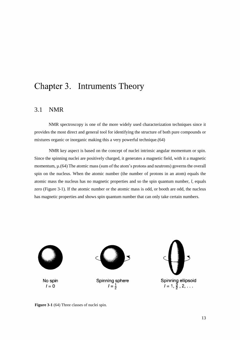
NMR key aspect is based on the concept of nuclei intrinsic angular momentum or spin.
Since the spinning nuclei are positively charged, it generates a magnetic field, with it a magnetic
momentum, µ.(64) The atomic mass (sum of the atom’s protons and neutrons) governs the overall
spin on the nucleus. When the atomic number (the number of protons in an atom) equals the
atomic mass the nucleus has no magnetic properties and so the spin quantum number, l, equals
zero (Figure 3-1). If the atomic number or the atomic mass is odd, or booth are odd, the nucleus
has magnetic properties and shows spin quantum number that can only take certain numbers.
Figure 3-1 (64) Three classes of nuclei spin.
14
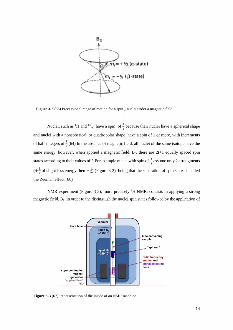
Nuclei, such as 1H and 13C, have a spin of 1
2 because their nuclei have a spherical shape
and nuclei with a nonspherical, or quadropolar shape, have a spin of 1 or more, with increments
of half-integers of 1
2.(64) In the absence of magnetic field, all nuclei of the same isotope have the
same energy, however, when applied a magnetic field, Bo, there are 2I+1 equally spaced spin
states according to their values of I. For example nuclei with spin of 1
2 assume only 2 arrangments
(+1
2 of slight less energy then −
1
2) (Figure 3-2) being that the separation of spin states is called
the Zeeman effect.(66)
NMR experiment (Figure 3-3), more precisely 1H-NMR, consists in applying a strong
magnetic field, Bo, in order to the distinguish the nuclei spin states followed by the application of
Figure 3-2 (65) Precessional range of motion for a spin 1
2 nuclei under a magnetic field.
Figure 3-3 (67) Representation of the inside of an NMR machine

15
an radio wave pulse that acts as a new temporary magnetic field, B1, whose frequency corresponds
to the Larmor frequency (angular frequency of the precessional motion in the magnetic moment).
This results in the excess lower state nuclei converting to higher states of energy through
absorption equal to the energy difference given by Bohr’s equation and whose frequency
corresponds to the resonance frequency. After some time, the excited state nuclei returns to its
lower energy state, originating a current that is recorded by the signal detection coils originating
at a peak in the NMR spectrum.
3.2 ATR FT-IR and ATR FT-IR microscopy
FT-IR is a very attractive technique widely used in fields such as chemistry, biology, and
biochemistry has it provides the identification of molecules with a high signal-to-noise ratio and
high resolution while giving spectra results that are analogous to fingerprints, meaning molecular
structures can only give one infrared spectrum.(68, 69)
Depending on the molecular geometry, different molecules possess different molecular
vibrations. In a nonlinear molecule, the number of ways a molecule can vibrate (i.e., the number
of vibrational modes) is given by 3N − 6 degrees of freedom where 3N degrees of freedom are
given by the translational motion and rotation motion over the x, y and z-axes.(70) In a linear
molecule, the rotation about the axis of the bond does not involve any change of the position of
the atoms, so one of the rotational degrees of freedom is lost thus possessing an additional
vibrational state mode, displayed in 3N − 5. Infrared spectroscopy derives from transitions
Figure 3-4 (70) Potential energy of a diatomic molecule as function of the atom’s separation with
quantized vibration quantum numbers displayed.

16
between quantized vibrational energy states (Figure 3-4). When the light absorbed by the atoms
present in the sample reaches the energy difference necessary to transition between the ground
state (υ=0) and first excited state (υ=1) the FT-IR detects the decrease in light intensity that was
lost to the excited atoms giving a peak in the absorbance scale [This transition is where most
vibrational modes are included and its radiation energy is in the mid-infrared spectrum (400 to
4000 cm-1)].(70) The absorbance of a sample is related to both the intensity of the background
and sample spectrums and the concentration of molecules in a sample via Beer’s Law.(71)
In ATR FT-IR, measuring a sample spectrum requires the use of radiation refraction
(Figure 3-5).(71) The essence of this technique relies on Snell’s law (equation 3-1) that describes
the behaviour of radiation when passes from one transparent medium to another with different
refractive index.(70)
Equation 3-1 Snell’s law.
𝜂1 sin 𝛳1 = 𝜂2 sin 𝛳2
Considering, η1 the refractive index of the crystal, η2 refractive index of the sample, ϴ1
and ϴ2 the angle of incidence and refraction incidence, according to this law, it is not possible to
obtain total internal reflectance if η2 > η1. Furthermore, if we increase the angle of incidence, to a
certain angle named critical angle, ϴc, all incidence angles equal or superior to ϴc will reflect
internally as shown in figure 3-5. Despite contradictory, ATR FT-IR gives a spectrum of
absorbance just like a “normal” FT-IR spectrum even though ATR is a reflectance technique.
By combining the mechanisms of infrared identification with microscope imagining, a
new spectrum of applications can be used to uncover the composition of specific areas of the
sample that it's being measured. The combination of two techniques is named hyphenated infrared
techniques. In this case, a detector is used to draw the so-called molecular map in a grid pattern
and within in the composition identification at specific spots chosen by the operator.(71)
Figure 3-5 (70) ATR module work principle.

17
3.3 AFM
Since the invention of this technique, AFM has been a very useful tool to uncover surface
morphology and chemical to physical properties of micron-to-nano structures at an atomic and
subnanometer scale.(72)
AFM as a technique works by using a sharp tip to map the surface and has it feels the
surface topology signals are sent via laser which is then reflected from the tip surface to a photo-
detector (Figure 3-6). The feedback signals are sent to a signal processing software, which
analyses and comprises a 2D or 3D plots.(72) Uncovering the surface topology can be made by
contact mode where the tip is dragged along the surface or by tapping mode which vibrates the
cantilever (object that holds the tip) at or near its resonance frequency to scan the surface. Despite
the different methods used to “feel” the surface, the local height of a surface (surface morphology
in AFM is made at each point, called pixel, of a 2D array that consists of the mapped surface) is
determined by measuring the vertical or Z displacement needed to touch the surface.(73)
Furthermore, although the principle of measuring the height of a sample is the same, different
mechanics in function of the technique are used. Looking more in-depth to the tapping mode
ability to measure the surface morphology, as it is the mechanism used in this work, this method
tracks the surface topology via amplitude of the cantilever. A Z scanner displaces at each pixel
the distance between the oscillating tip and the sample to keep the amplitude constant during
surface measurements (Figure 3-7). To obtain clear images during these experiments, the quality
of the data must provide high resolution for this effect and one factor that is crucial for this
endeavour is the precise control of the tip-surface interactions. These interactions are based on
Figure 3-6 (73) Schematic representation of AFM procedure.

18
continuum mechanics, long-range van der Waals forces, capillary forces, short-range forces,
electrical double layer force in a liquid, and contamination effects.(72) Each force represents a
different way that the tips interacts with the surface, and thus to produce a good atomic resolution
image the tip must be able to counteract the tip-surface interactions described above.(72)
Figure 3-7 (73) AFM tapping mode mechanism.

19
Experimental methods
4.1 Materials
The following materials were purchased from Sigma-Aldrich, USA: 4 cyano-4-(phenyl-
carbonothioylthio) pentanoic acid, CPAD, (>97%), 2,2′-Azobis (2-methylpropionamidine)
dihydrochloride, VA-044, (97%), BIBB, (98%), pyridine (≥99%), copper(II) bromide, CuIIBr2,
diethyl ether (DEE) (>99%), NIPAM (≥99), N,N,N’,N’’,N’’-Pentamethyldiethylenetriamine,
PMDETA, (99%), and all deuterated solvents for 1H-NMR, except for chloroform-d, CDCl3
which was acquired from Cambridge Isotope Laboratories (Inc., USA). HEMA (97%), also
purchased from Sigma-Aldrich, was purified from the oxygen inhibitor (remove the monomethyl
ether hydroquinone) by passing the polymerizable vinyl monomer through a basic alumina
(Brockmann I activated grade from Sigma-Aldrich with 50-200 µm pore size range) and filtered
through Whatman® SPARTAN® 30/0.2 RC syringe filters. Copper(I) bromide, CuIBr, was
purchased from Sigma-Aldrich as well and it was purified in glacial acetic acid (anhydrous acetic
acid). The greenish powder was stirred for at least 2 hours in acetic acid for 3 times. Afterwards,
the salt was washed with ethanol. The salt finally was filtered, rinsed three times with ethanol and
dried under vacuum overnight. The catalyst was stored in the dark and in nitrogen glove box.
Premium grade, Ensure @, solvents namely, methanol (MeOH), ethanol, acetone and DMF, were
obtained from Merck KGaA, GER and the remaining solvents THF, hexane, heptane, toluene,
chloroform, were purchased from Biosolve Chimie SARL (all belonging to Analytical grade). All
the water used was ultra-pure water dispensed through a Milli-Q system from Millipore
Corporation, USA.
Auxiliary equipment for all reactions and experiments made include VWR Blue Nitrile
powder-free disposable gloves and samples vials with snap-caps, BRAUN Sterican® needles, BD
DiscarditTM II syringes, Swann-Morton® surgical scalpel blade No.23, Eppendorf® epT.I.P.S.,
Greiner bio-one TM CELLSTAR® test tubes (to store the several inks produced), gold substrates
(1x1cm2) were cut from a silicon wafer coated with 100 mm sputtered gold (Au).
20
4.2 Molecular Characterization
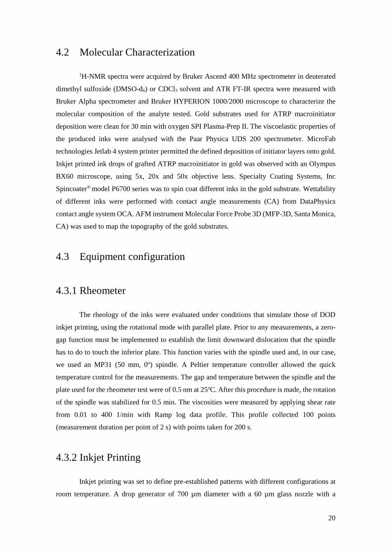
1H-NMR spectra were acquired by Bruker Ascend 400 MHz spectrometer in deuterated
dimethyl sulfoxide (DMSO-d6) or CDCl3 solvent and ATR FT-IR spectra were measured with
Bruker Alpha spectrometer and Bruker HYPERION 1000/2000 microscope to characterize the
molecular composition of the analyte tested. Gold substrates used for ATRP macroinitiator
deposition were clean for 30 min with oxygen SPI Plasma-Prep II. The viscoelastic properties of
the produced inks were analysed with the Paar Physica UDS 200 spectrometer. MicroFab
technologies Jetlab 4 system printer permitted the defined deposition of initiator layers onto gold.
Inkjet printed ink drops of grafted ATRP macroinitiator in gold was observed with an Olympus
BX60 microscope, using 5x, 20x and 50x objective lens. Specialty Coating Systems, Inc
Spincoater® model P6700 series was to spin coat different inks in the gold substrate. Wettability
of different inks were performed with contact angle measurements (CA) from DataPhysics
contact angle system OCA. AFM instrument Molecular Force Probe 3D (MFP-3D, Santa Monica,
CA) was used to map the topography of the gold substrates.
4.3 Equipment configuration
4.3.1 Rheometer
The rheology of the inks were evaluated under conditions that simulate those of DOD
inkjet printing, using the rotational mode with parallel plate. Prior to any measurements, a zero-
gap function must be implemented to establish the limit downward dislocation that the spindle
has to do to touch the inferior plate. This function varies with the spindle used and, in our case,
we used an MP31 (50 mm, 0o) spindle. A Peltier temperature controller allowed the quick
temperature control for the measurements. The gap and temperature between the spindle and the
plate used for the rheometer test were of 0.5 nm at 25oC. After this procedure is made, the rotation
of the spindle was stabilized for 0.5 min. The viscosities were measured by applying shear rate
from 0.01 to 400 1/min with Ramp log data profile. This profile collected 100 points
(measurement duration per point of 2 s) with points taken for 200 s.
4.3.2 Inkjet Printing
Inkjet printing was set to define pre-established patterns with different configurations at
room temperature. A drop generator of 700 µm diameter with a 60 µm glass nozzle with a
21
piezoelectric crystal is applied an external electric load. A uniform waveform with a 1 µs rise
time, varying dwell and pulses used, 1 µs fall was employed with an adjustable frequency to
obtain the best drops for each ink varying between 450 and 500 Hz. Before any experiment nozzle
purification was made with a solution of hydrogen chloride with demineralized water to clean the
nozzle.
4.3.3 Spin coating
Uniformly grafting layers were prepared by rotating the sample at 2000 Hz for 1 min. To
prevent sample displacement, the sample was put on a vacuum plate.
4.3.4 CA
Water contact values for the tested substrates were determined by adding a water drop to
the surface and calculating the angle value of the generated droplet.
4.3.5 AFM
To analyse the height and roughness of the gold surfaces a silica cantilever 2 was used. After
the cantilever was brought to its resonance frequency vibration, the drop was located and after
calibrating the laser with the cantilever surface the experiments were performed with a scan size
of 60 µs, scan rate 0.10 Hz at 15 µm/s. The amplitude was set at 19.53 mV with a frequency of
89.596 kHz.
4.4 Fabrication method
4.4.1 RAFT Polymerization of HEMA
Two 100 mL round-bottom flasks were used to perform the RAFT polymerization of the
monomer HEMA (10 mL, 0.082 mol) and the chain transfer agent, CPAD (0.0229 g, 0.82 mmol),
with VA-044 initiator (0.0133 g, 0.41 mmol), water (5 mL) and methanol (5 mL) solvent media
in a different flask. Also, DMF (1 mL) was added to the RAFT polymerization solution an internal
reference for the evaluation of the conversion via 1H-NMR. The flasks were sealed with a rubber
septum and degassed by bubbling with argon gas and stirred for approximately 30 min. Monomer-
CPAD solution was transferred into the thermal radical initiator solution. The mixture was then

22
heated up to 450C. After the desired time, the polymerization was stopped by quenching and by
allowing the reaction mixture to contact air. The precipitated polymer was purified 3 times by
precipitating in DEE. Finally, the purified polymer was dried in vacuum until all solvent and
unreacted monomer was removed as confirmed by 1H-NMR and ATR FT-IR spectra. HEMA
conversion was calculated comparing the integration areas of the monomer double bond between
6.07 and 5.62 ppm that will decrease as the monomer is converted. Purified 6th PHEMA is shown
in appendix A and the solubility table for other PHEMA of different molecular weight is displayed
in appendix B.
4.4.2 Preparation of PBIEM
A 0.397 g sample of PHEMA (-OH groups, 3.05 mmol) was dissolved in 4.90 mL of
pyridine. Then 1.402 g (6.1 mmol) of BIBB was added dropwise at 0oC in 60 min. The reaction
mixture was left to stir at the same temperature for 3h followed by stirring at room temperature
for 24 h. The insoluble salt was removed by filtration and the dissolved mixture was precipitated
in hexane. The modified polymer was dried under vacuum. After 1H-NMR analysis, an absolute
quantitative conversion was obtained as shown in figure 5-4. PBIEM physical characteristics can
be visualized in appendix C.

23
Results and discussion
5.1 RAFT Polymerization of HEMA
RAFT polymerization technique was used to synthesise the ATRP macroinitiator. As
described in the subchapter 1.2.2, polymer chain growth occurs when degenerative chain transfer
between macro-RAFT agent and propagating radical take place so, kinetically, it is essential that
the appropriate choice of RAFT agent is made regarding the monomer as the poor choice of this
compounds, because the inherent nature of this polymerization, can lead from suppression of rate
of polymerization to uncontrolled radical polymerization resulting in broad molecular weight
polymers. For this reason, CPAD CTA (Scheme 5-1) was chosen as dithioesters are one of the
most activated RAFT agents and usual choice to polymerize methacrylate monomers as is the
case with HEMA.(74) Furthermore, the dithiobenzoyl group present in CPAD will play a critical
role in the end-use application namely self-assembly monolayers in gold. A water-soluble with a
low decomposition temperature azo initiator in VA-044 was chosen to initiate the radical
polymerization by thermal decomposition. The procedure RAFT polymerization was carried out
several times with the aim to evaluate the effect of the solvent on the length of the macromolecules
(Table 5-1). Despite imploring different reactions mixtures, the same polymeric reaction
temperature was established at 45oC. Also, the [M]:[RAFT agent]:[Initiator] ratio was maintained
Scheme 5-1 RAFT polymerization of HEMA using CPAD as the CTA.
HEMA
VA-044 in Water/Methanol
450C
PHEMA
CPAD
24
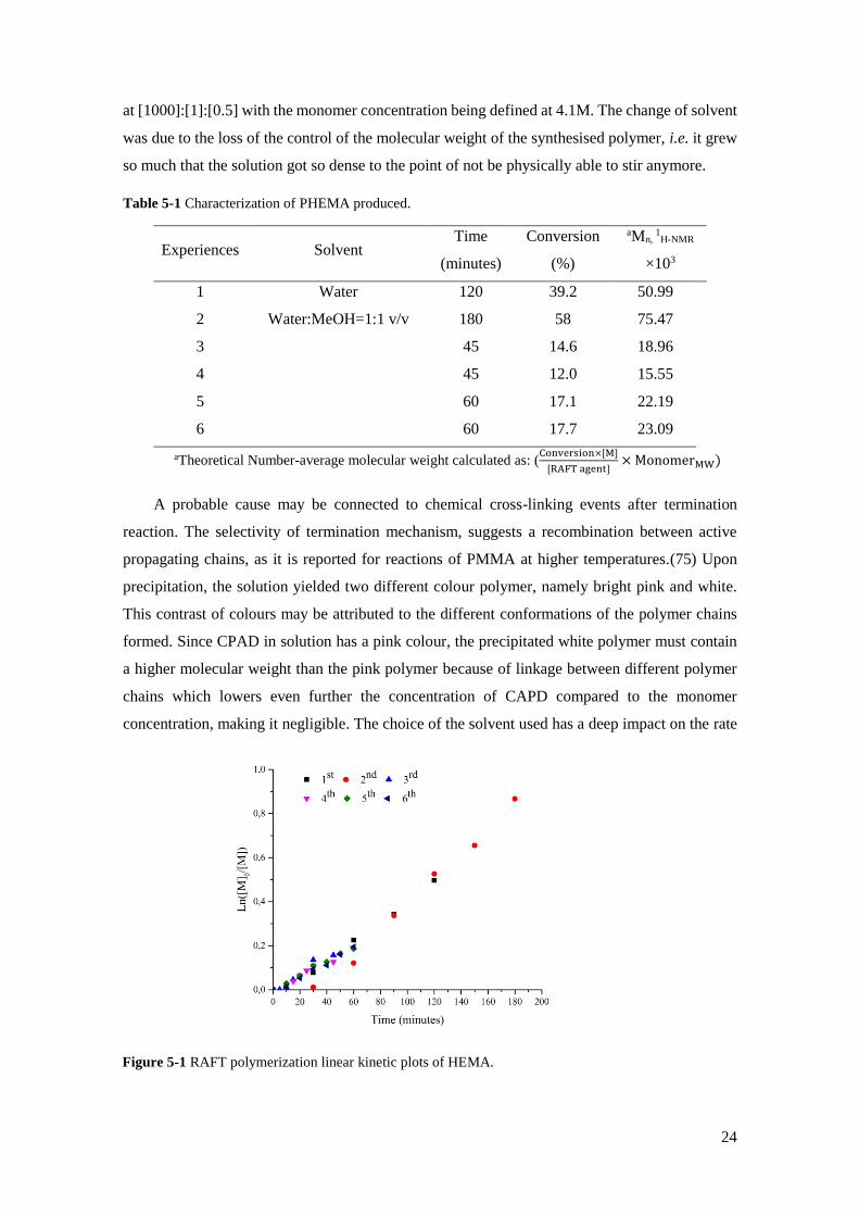
at [1000]:[1]:[0.5] with the monomer concentration being defined at 4.1M. The change of solvent
was due to the loss of the control of the molecular weight of the synthesised polymer, i.e. it grew
so much that the solution got so dense to the point of not be physically able to stir anymore.
Table 5-1 Characterization of PHEMA produced.
Experiences Solvent Time
(minutes)
Conversion
(%)
aMn, 1H-NMR
×103
1 Water 120 39.2 50.99
2 Water:MeOH=1:1 v/v 180 58 75.47
3 45 14.6 18.96
4 45 12.0 15.55
5 60 17.1 22.19
6 60 17.7 23.09
aTheoretical Number-average molecular weight calculated as: (Conversion×[M]
[RAFT agent]× MonomerMW)
A probable cause may be connected to chemical cross-linking events after termination
reaction. The selectivity of termination mechanism, suggests a recombination between active
propagating chains, as it is reported for reactions of PMMA at higher temperatures.(75) Upon
precipitation, the solution yielded two different colour polymer, namely bright pink and white.
This contrast of colours may be attributed to the different conformations of the polymer chains
formed. Since CPAD in solution has a pink colour, the precipitated white polymer must contain
a higher molecular weight than the pink polymer because of linkage between different polymer
chains which lowers even further the concentration of CAPD compared to the monomer
concentration, making it negligible. The choice of the solvent used has a deep impact on the rate
Figure 5-1 RAFT polymerization linear kinetic plots of HEMA.
25
a
h
c
d
e b
f g
constants of many homopolymerization reactions that contain monomers with hydroxy groups,
such as HEMA.(15) Since water is a bad solvent for PHEMA, the probability of termination due
to competing side reactions increase and controlled synthesis of the ATRP macroinitiator
backbone proves more challenging as to just use a cosolvent that decreases the medium polarity
slowing down the reaction to obtain better kinetics. Comparing the experiments obtained at the
same time, namely at 45 and 60 minutes, similar conversions were achieved emphasizing the
controlled nature of the chosen polymeric conditions. Linear kinetic semilogarithmic plots (figure
5-1) are shown that corroborate with the "living" polymerization mechanism of slow growth of
living chains which are the opposite of FRP. The second experience shows an inhibition time until
30 minutes that can be explained by a delay in heating the reaction mixture to the predetermined
value of 450C. Additionally, it is clear in all RAFT polymerizations the presence of an initial
phase that has practically no polymerization conversion. This induction period that occurs,
approximately, in the ten minutes of all reactions also can be explained by the heating of the
reaction mixture, however, the concept of low reinitiation rate of the leaving group should also
be considered.(76),(77) Observing the conversion over time in accordance with the solvent choice,
interesting results emerge, when at 45 min, every experiment besides the second one appears to
have faster polymerizations rates which go against what is theoretically expected.
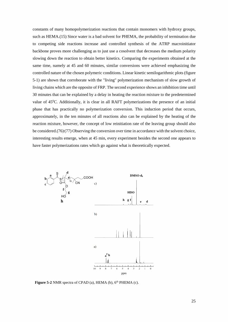
Figure 5-2 NMR spectra of CPAD (a), HEMA (b), 6th PHEMA (c).
h g f
HDO
DMSO-d6
d e
a b c

26
A reasoning for this contradiction derives from systematic data collection errors when
obtaining conversions through the 1H-NMR spectra. Figure 5-2 containing the 1H-NMR spectra
(DMSO-d6; δ ppm) of 6th PHEMA displays the typical main chain polymer peaks at: 0.70-1.00
[3H, -CH3]; 1.90 [2H, -CH2- backbone]; 2.52-2.53 DMSO-d6 solvent signal; 3.19 [3H, -CH3 from
methanol]; 3.5 water peak; 3.56-4.16 [4H, -CH2- from HEMA]; 5.21 [1H, -OH]. ATR FT-IR
spectrum (cm-1) for 6th PHEMA, displayed in figure 5-3 shows the characteristic absorption bands:
3390 cm-1[ʋ(O-H)]; 2945 and 2882 cm-1[ʋ(C-H)]; 1720 cm-1[ʋ(C=O)]; 1152 cm-1[δ(O-H)].
Additionally, the unreacted monomer band, 1634 cm-1 [ʋ(O-H)] does not appear further
confirming the purity of the synthesised polymer.
5.2 Preparation of PBIEM
The preparation of ATRP macroinitiator active sites is discussed here. As it was said in
the subchapter 1.2.3 ATR polymerization kinetics generally operates under persistent radical
effect, where a transition metal complex traps the growing propagating radical chains in a
deactivation process reaction. Because the composition of the dormant species consists of an
initiating alkyl halide it is important that the latter reactive species be able to efficiently initiate
an ATRP reaction for the selected monomer. In this sense, knowing different reactivity values of
alkyl halides is crucial for appropriate initiator choice, especially for lower targeted DPn.(34) For
the esterification reaction (Scheme 5-2), BIBB was chosen since it is a very common alkyl halide
initiator precursor for ATRP due to high reactivity rate constant values.(16) PHEMA with
different molecular weights were used to synthesize PBIEM (Table 5-2). Qualitative complete
Figure 5-3 ATR FT-IR spectra of 6th PHEMA with highlighted characteristic peaks.
ʋ(O
-H)
ʋ(C
-H)
ʋ(C
=O
)
δ(O
-H)

27
conversion was achieved in booth experiments as the methylene protons adjacent to the hydroxy
group switch from 4.14-4.10 to 4.31-4.30 due to the difference of the methylene protons being
adjacent instead to the ester group of PBIEM.(78) Because PHEMA was not dissolving in CDCl3,
comparative analyses on the shift of the methylene protons were made with HEMA NMR spectra.
A representative 1H-NMR and ATR FT-IR of PBIEM is displayed figure 5-4 and figure 5-5,
respectively. The 1H-NMR spectra (CDCl3; δ ppm) of PBIEM can be observed: 0.70-1.00 [3H, -
CH3]; 1.78 HDO solvent peak; 1.90 [2H, -CH2- from the backbone and –CH3 from BIBB]; 4.14-
4.31 [4H; -CH2 from HEMA]; 7.20 CDCl3 solvent peak; Excess pyridine also appears after the
solvent peak (Appendix D). Characteristic ATR FT-IR spectrum peaks (cm1) for PBIEM are
shown: 680 cm-1[ʋ(C-Br)]. Observing the ATR FT-IR data of PBIEM originated from 1st PHEMA
51kda (PBIEM-A), 3416 cm-1 [ʋ(O-H)] region still appears in the spectrum. Being that all HEMA
monomer was clean from the purified polymer, as it shows in figure 5-2, it is plausible to assume
that total conversion was not achieved contrary of what has been reported by literature. This
makes conversion confirmation extremely difficult because all PHEMA synthesised didn’t
dissolve in CDCl3, eliminating the possibility of quantitative peak shift comparison. The solubility
of the ATRP macroinitiator was tested to acquire information about possible ink solvents for
inkjet printing (Appendix E).
Table 5-2 PBIEMs synthesised from PHEMA.
Experiment ATRP macroinitiator
backbone
Conversion
%
1 6th PHEMA (22 kDa) 100%
2 1st PHEMA (51 kDa) 100%
PHEMA
Pyridine at 00C
PBIEM
Scheme 5-2 Esterification reaction of PHEMA with BIBB
BIBB

28
f
Figure 5-4 NMR of a) PBIEM-A, and b) HEMA in CDCl3. Two dashed lines exhibit the shift of the
methylene protons after BIBB coupling.
Figure 5-5 ATR FT-IR of a) PBIEM-A and b) PHEMA. Typical PBIEM peak is showcased in 2).
g
i
i
g f
ʋ(C
-H) ʋ
(C-B
r)
ʋ(C
=O
)
29
5.3 Inkjet Printing
In this section, printability factors, as described in the subchapter 1.2.4, namely as
viscosity, wettability and surface tension were studied. The concept of self-assembly disulfide-
gold monolayers will also be analysed as well as the probability of the end-group attachment to
the gold surface in function of the macroinitiator length.
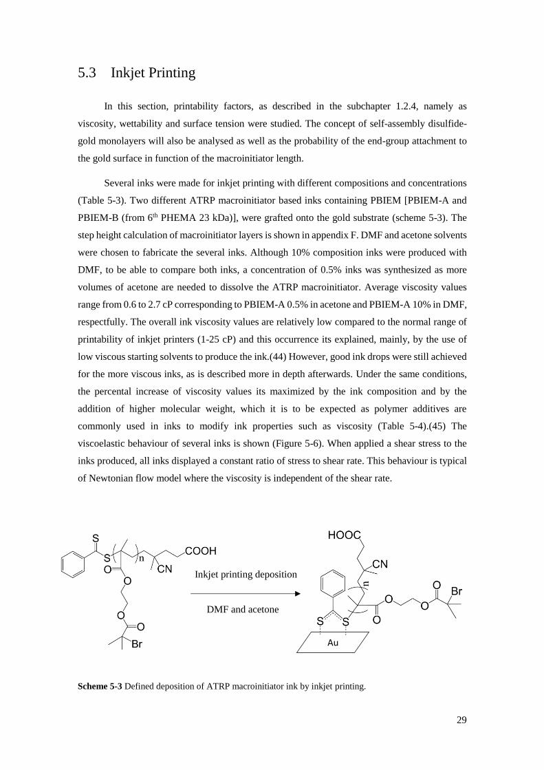
Several inks were made for inkjet printing with different compositions and concentrations
(Table 5-3). Two different ATRP macroinitiator based inks containing PBIEM [PBIEM-A and
PBIEM-B (from 6th PHEMA 23 kDa)], were grafted onto the gold substrate (scheme 5-3). The
step height calculation of macroinitiator layers is shown in appendix F. DMF and acetone solvents
were chosen to fabricate the several inks. Although 10% composition inks were produced with
DMF, to be able to compare both inks, a concentration of 0.5% inks was synthesized as more
volumes of acetone are needed to dissolve the ATRP macroinitiator. Average viscosity values
range from 0.6 to 2.7 cP corresponding to PBIEM-A 0.5% in acetone and PBIEM-A 10% in DMF,
respectfully. The overall ink viscosity values are relatively low compared to the normal range of
printability of inkjet printers (1-25 cP) and this occurrence its explained, mainly, by the use of
low viscous starting solvents to produce the ink.(44) However, good ink drops were still achieved
for the more viscous inks, as is described more in depth afterwards. Under the same conditions,
the percental increase of viscosity values its maximized by the ink composition and by the
addition of higher molecular weight, which it is to be expected as polymer additives are
commonly used in inks to modify ink properties such as viscosity (Table 5-4).(45) The
viscoelastic behaviour of several inks is shown (Figure 5-6). When applied a shear stress to the
inks produced, all inks displayed a constant ratio of stress to shear rate. This behaviour is typical
of Newtonian flow model where the viscosity is independent of the shear rate.
Au
Scheme 5-3 Defined deposition of ATRP macroinitiator ink by inkjet printing.
Inkjet printing deposition
DMF and acetone
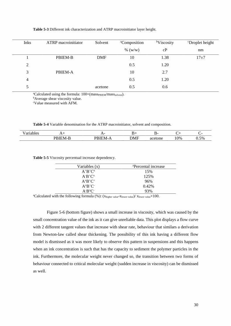
30
Table 5-3 Different ink characterization and ATRP macroinitiator layer height.
aCalculated using the formula: 100×(massPBIEM/masssolvent). bAverage shear viscosity value. cValue measured with AFM.
Table 5-4 Variable denomination for the ATRP macroinitiator, solvent and composition.
Variables A+ A- B+ B- C+ C-
PBIEM-B PBIEM-A DMF acetone 10% 0.5%
Table 5-5 Viscosity percentual increase dependency.
Variables (x) aPercental increase
A+B+Cx 15%
A-B+Cx 125%
AxB+C+ 96%
AxB+C- 0.42%
A-BxC- 93% aCalculated with the following formula (%): (xhigher value-xlower value)/ xlower value×100.
Figure 5-6 (bottom figure) shows a small increase in viscosity, which was caused by the
small concentration value of the ink as it can give unreliable data. This plot displays a flow curve
with 2 different tangent values that increase with shear rate, behaviour that similars a derivation
from Newton-law called shear thickening. The possibility of this ink having a different flow
model is dismissed as it was more likely to observe this pattern in suspensions and this happens
when an ink concentration is such that has the capacity to sediment the polymer particles in the
ink. Furthermore, the molecular weight never changed so, the transition between two forms of
behaviour connected to critical molecular weight (sudden increase in viscosity) can be dismissed
as well.
Inks ATRP macroinitiator Solvent aComposition
% (w/w)
bViscosity
cP
cDroplet height
nm
1 PBIEM-B DMF 10 1.38 17±7
2 0.5 1.20
3 PBIEM-A 10 2.7
4 0.5 1.20
5 acetone 0.5 0.6
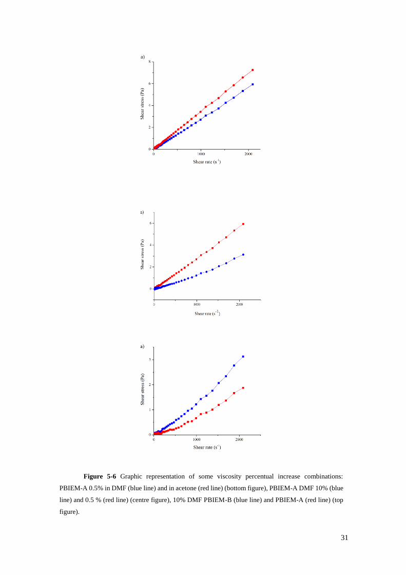
31
Figure 5-6 Graphic representation of some viscosity percentual increase combinations:
PBIEM-A 0.5% in DMF (blue line) and in acetone (red line) (bottom figure), PBIEM-A DMF 10% (blue
line) and 0.5 % (red line) (centre figure), 10% DMF PBIEM-B (blue line) and PBIEM-A (red line) (top
figure).

32
The practical difference in viscosity it's clearly demonstrated (Figure 5-7) where the
filament rupture happens sooner in the less viscous ink. The low filament length and absence of
satellite drops are correlated with Newtonian printing behaviour.(79) Upon printing, the shape of
the droplet after the impact with the substrate was affected depending on which ink used.
Experimental visualization of the droplet impact in the substrate is observed (Figure 5-8).
Applying a more depth analysis visualization of the two different solvent inks, any of the DMF
ink showed a more prominent capability to sustain the impact with the substrate in comparison
with the acetone ink and thus having a more of a uniform shape throughout its total volume. The
availability of producing define patterns with the inkjet printer is but a consequence of the ink
produced, and in coating applications, the more uniform deposition inks would be more suited
than more spread out deposition inks.(80) Ink droplets with a volume of 113 pL were achieved.
Figure 5-8 PBIEM-A 0.5% in acetone (left side) PBIEM-A 10% in DMF (right side).
50 µm
100 µm
150 µm
200 µm
Figure 5-7 Drop formation of PBIEM-A 10% in DMF (a), and PBIEM-A 0.5% in acetone (b).
50 µm
75 µm
100 µm
150 µm
1000 µm
1000 µm 1000 µm
1000 µm
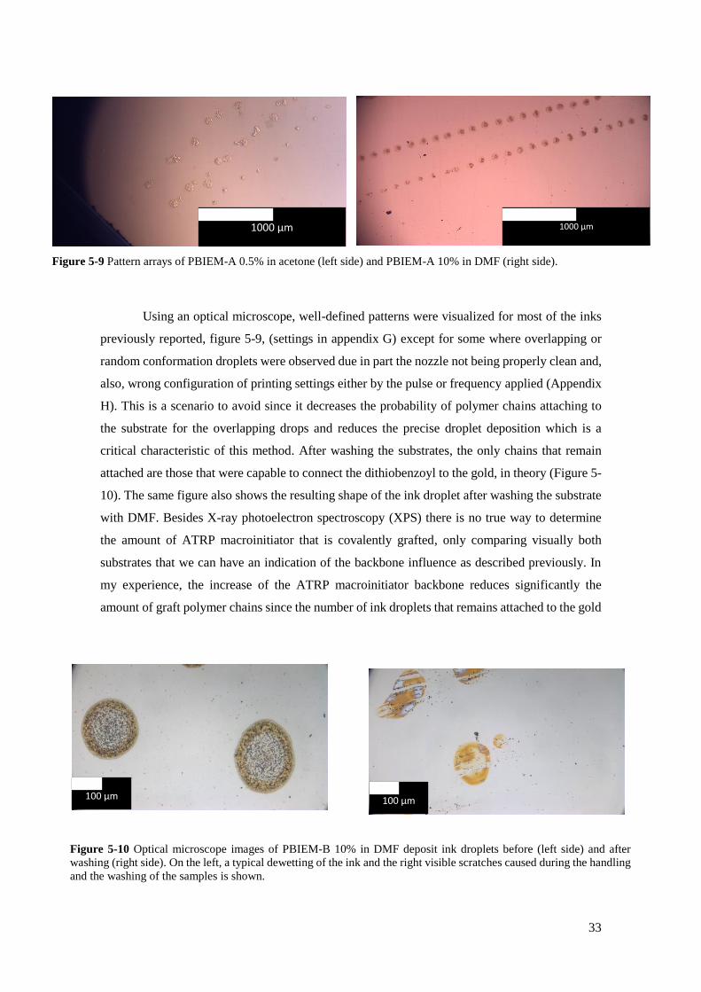
33
Using an optical microscope, well-defined patterns were visualized for most of the inks
previously reported, figure 5-9, (settings in appendix G) except for some where overlapping or
random conformation droplets were observed due in part the nozzle not being properly clean and,
also, wrong configuration of printing settings either by the pulse or frequency applied (Appendix
H). This is a scenario to avoid since it decreases the probability of polymer chains attaching to
the substrate for the overlapping drops and reduces the precise droplet deposition which is a
critical characteristic of this method. After washing the substrates, the only chains that remain
attached are those that were capable to connect the dithiobenzoyl to the gold, in theory (Figure 5-
10). The same figure also shows the resulting shape of the ink droplet after washing the substrate
with DMF. Besides X-ray photoelectron spectroscopy (XPS) there is no true way to determine
the amount of ATRP macroinitiator that is covalently grafted, only comparing visually both
substrates that we can have an indication of the backbone influence as described previously. In
my experience, the increase of the ATRP macroinitiator backbone reduces significantly the
amount of graft polymer chains since the number of ink droplets that remains attached to the gold
Figure 5-10 Optical microscope images of PBIEM-B 10% in DMF deposit ink droplets before (left side) and after
washing (right side). On the left, a typical dewetting of the ink and the right visible scratches caused during the handling
and the washing of the samples is shown.
100 μm 100 μm
1000 μm
Figure 5-9 Pattern arrays of PBIEM-A 0.5% in acetone (left side) and PBIEM-A 10% in DMF (right side).
1000 μm

34
after cleaning was substantially less. Of all inks produced, the PBIEM-B 10% in DMF proved to
have the best grafting macromolecules after cleaning ratio (figure 5-11). Another critical visual
effect observed in some inks deposits was the coffee-ring effect, as displayed in (Figure 5-10).
This effect is observed when a non-uniform evaporation flux in a liquid-gas interface (surface
tension gradient) or a thermal-induced gradient induces a capillary flow of suspended particles in
a droplet and the Marangoni flow which governs the internal flow in a droplet (it’s the key factor
for the appearance of the coffee stain effect).(80) This appearance of this effect in some deposit
inks is unexpected since polymer contained in the ink is completely dissolved. Besides optical
microscopy contact angle measurements were also used to measure the difference in wettability
of clean and grafted as another way to prove the presence of deposit ATRP macroinitiator.
Exceptionally for this effect, spin-coated deposition method was used in a gold substrate with the
4th ink and the 5th ink produced. Starting with a gold substrate with a contact angle of <10o
modified substrates with 61.3o +/- 3 for 4th and 57.0o +/- 5 for the 5th ink. Finally, infrared
microscopy was used to prove the presence of ATRP macroinitiator grafted to the gold surface in
comparison by comparison with the clean gold (Figure 5-12). Shifted typical PBIEM peak is
displayed at 750 cm-1 [ʋ(C-Br)]. Again, 3416 cm-1 peaks [ʋ(O-H)] also appear indicating the
presence of possible unreacted monomer. Unfortunately, with this spectrum, it’s not clearly
observed the disulfide bond. Combining these three methods we can conclude that we have a
covalent bond between the ATRP macroinitiator and the gold substrate.
Figure 5-11 Patterned ink drops constituted of PBIEM-B 10% in DMF.
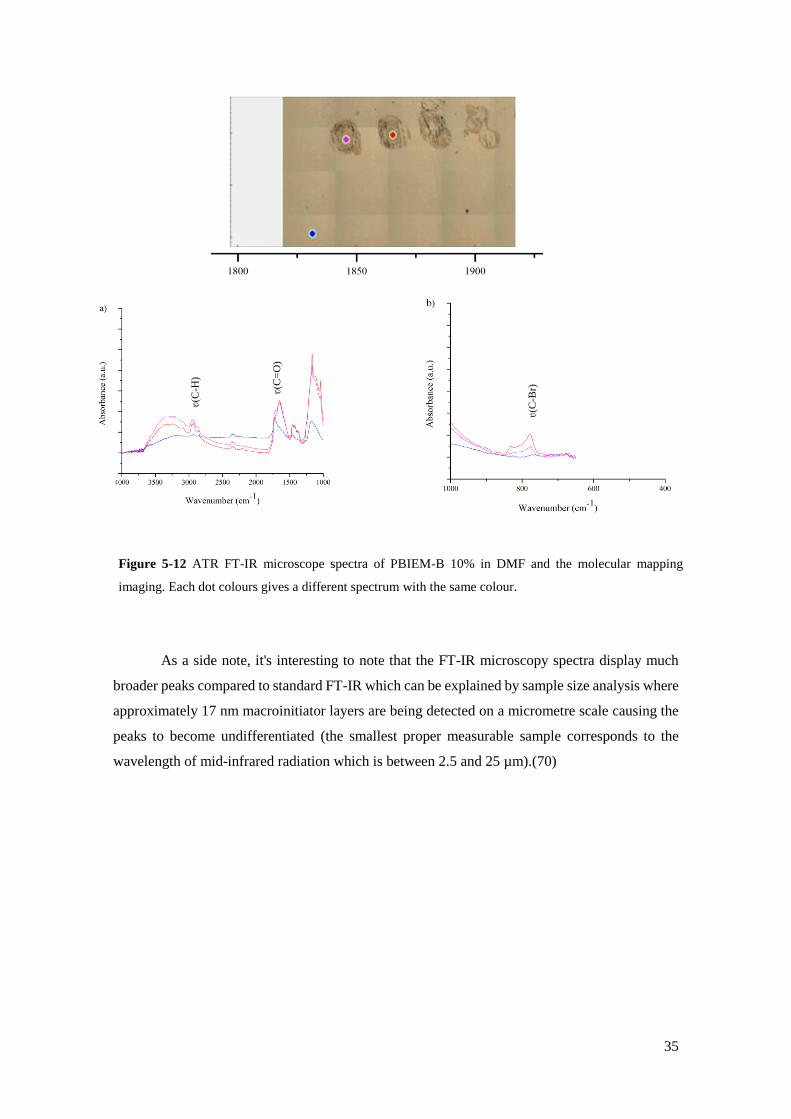
35
As a side note, it's interesting to note that the FT-IR microscopy spectra display much
broader peaks compared to standard FT-IR which can be explained by sample size analysis where
approximately 17 nm macroinitiator layers are being detected on a micrometre scale causing the
peaks to become undifferentiated (the smallest proper measurable sample corresponds to the
wavelength of mid-infrared radiation which is between 2.5 and 25 µm).(70)
ʋ(C
-Br)
Figure 5-12 ATR FT-IR microscope spectra of PBIEM-B 10% in DMF and the molecular mapping
imaging. Each dot colours gives a different spectrum with the same colour.
ʋ(C
=O
)
ʋ(C
-H)

36
Blank page
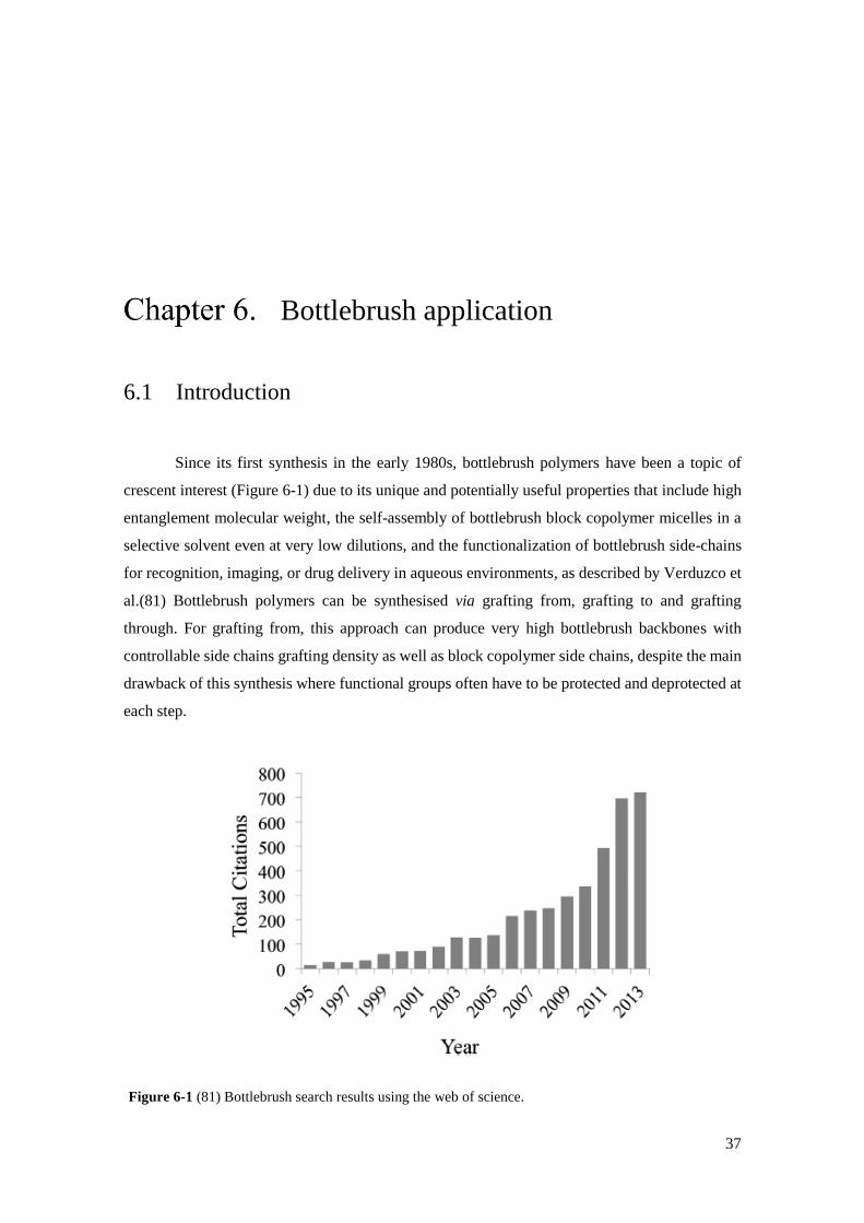
37
Bottlebrush application
6.1 Introduction
Since its first synthesis in the early 1980s, bottlebrush polymers have been a topic of
crescent interest (Figure 6-1) due to its unique and potentially useful properties that include high
entanglement molecular weight, the self-assembly of bottlebrush block copolymer micelles in a
selective solvent even at very low dilutions, and the functionalization of bottlebrush side-chains
for recognition, imaging, or drug delivery in aqueous environments, as described by Verduzco et
al.(81) Bottlebrush polymers can be synthesised via grafting from, grafting to and grafting
through. For grafting from, this approach can produce very high bottlebrush backbones with
controllable side chains grafting density as well as block copolymer side chains, despite the main
drawback of this synthesis where functional groups often have to be protected and deprotected at
each step.
Figure 6-1 (81) Bottlebrush search results using the web of science.

38
Grafting to enables the separate and precise characterization of both backbone and side
chains, however, it’s not been widely used, since it produces bottlebrush with low grafting
densities and as it happens with grafting through, low reactivity of polymeric reagents and
difficult coupling reaction as a result of steric hinderance interactions between side chains.(81,
82) Grafting trough provides full grafting density of the backbone with a very simplistic method,
despite reported unreacted macromonomer being hard to remove from the final product.(81) As
in the work performed, grafting from an ATRP macroinitiator is displayed in figure 6-2.
6.2 Preparation of bottlebrush
First, five 50 mL flasks containing different compounds were prepared separately. In the
first two flasks NIPAM (2.7 g, 0.238 mol), PMDETA (34 µL, 0.238 mmol) were dissolved in 30
mL of acetone. In the third flask, CuIBr (11.4 mg, 0.079 mmol) and CuIIBr2 (1.8 mg, 0.0079
mmol). In the fourth flask, PBIEM (66 mg, 0.238 mmol) was dissolved in 10 mL of acetone. The
fifth flask contained an inkjet printed grafted to gold ATRP macroinitiator. All flasks were sealed
with a rubber septum and degassed by bubbling with argon and stirred for approximately 30 min.
Materials from the first flask were added to the second flask. This intermediate solution was then
transferred to the remaining flasks (the fourth and fifth flask, respectfully). The two solutions
were put in an ice bath and left stirring for 24 h. Synthesised bottlebrush in solution was
precipitated by drying in N2 and its characterization was performed using 1H-NMR. Grafted from
bottlebrush copolymers were extracted from the solution dried in N2 and its composition was
verified by ATR FT-IR microscope. Bottlebrush present in solution after precipitation is shown
Scheme 6-1 Inkjet printing of ATRP macroinitiator (left side) with subsequent bottlebrush synthesis via
grafting form.

39
in appendix I. The conversion of bottlebrush side chain mas made by calculating the decrease of
the monomer double bond, CH2=CH between 5.5-6.5 ppm (Appendix J)
In the second method of producing PNIPAM bottlebrush side chains, 1.41 g (12.46 mmol)
NIPAM, 18.4 mg (0.12 mmol) CuIBr, 79.1 µl (0.378 mmol) PMDETA in 20 mL of acetone, 35
mg (0.12 mmol) PBIEM in 10 mL of acetone and grafted PBIEM in 10 mL of acetone were placed
in four 50 mL flasks under dry argon and stirred for 1 hour at room temperature (the first two
monomer flasks had the same composition). After degassing, the monomer flask was added to the
remaining flasks, put in an ice bath for 24h under stirring. Precipitation and characterization were
the same as the method described before.
6.3 Results and discussion
An example of a final possible application, the synthesis of a stimuli-responsive monomer
was chosen to produce the side chains of the bottlebrush. Monomer NIPAM chosen as the homo
side chain polymer as is one of the most widely studied in stimuli-responsive polymers due to the
lower critical solution temperature, LCST, (Temperature above which such polymers become
insoluble due to a change in volume conformation) of ≈ 32oC in water, meaning that visual
confirmation of successful bottlebrush synthesis is easily obtained.(83)
Two different polymerization methods as described in subchapter 6.2 were utilized for
bottlebrush fabrication. Exact conditions of this polymerization were not found in the literature
(Table 6-1) so slight changes to the procedure, namely the solvent used in the reaction mixture,
had to be implemented as booth literature recipes used a bad solvent, THF, relatively to all ATRP
macroinitiators produced and thus to be able to dissolve them, acetone was chosen.
Au Au
PBIEM
BIEM)
PBIEM-g-PNIPAM
BIEM) Scheme 6-2 Bottlebrush side chain synthesis by ATRP of NIPAM
NIPAM
BIEM)
Acetone at 0oC
BIEM)

40
Table 6-1 ATRP of NIPAM from the ATRP macroinitiator characterization.
aConversion formula is given as: MonomerMW ×Conversion ×[M]
[PBIEM]
ATRP fractions conditions [M]:[PBIEM]:[CuIBr]:[CuIIBr2]:[Ligand] were [300]:[3]:[1]:[0.1]:[3]
for the first procedure and [100]:[1]:[1]:[-]:[3] for the second procedure. The solvent influence in
ATRP reactions is very substantial on the polymerization constant rates and its effect is verified
in both experiences but particularly in the first experience which resulted in the need to change
the method due to the very low grafted side chains conversion. The ATR FT-IR microscope
spectra (cm-1) for the first bottlebrush poly(PBIEM-graft-PNIPAM) (PBIEM-g-PNIPAM) shows
the characteristic secondary amine absorption bands that belong to the NIPAM monomer: 1600
cm-1[ʋ(N-H)]. Besides the 2% NIPAM side chain conversion another interesting occurrence in
the first experience was the incapability to precipitate the bottlebrush present in solution with the
following solvents: Water, ethanol, methanol, chloroform, DEE, toluene, hexane, heptane. As it
happened in the first experience, the second polymerization revealed to be hard to precipitate as
well. The second polymerization also revealed something interesting and that was, by mistake
degassing of the CuIBr containing flask was not properly done and as a result, a blue colour
solution appears (Typical colour of the deactivator, CuIIBr). When this flask was added to the
ATRP macroinitiator flask, the solution turned instantly to green, signifying the presence of
CuIBr. For that to happen some reduction had to take place and a possible reducing agent was the
ATRP macroinitiator end-group (After oxidation the dithiobenzoyl group converts to disulfide).
Again, after bottlebrush synthesis, ATR FT-IR microscope was used to characterize the
modified substrates. However, neither substrate showed the bottlebrush spectra. The spectra of
the expected bottlebrush were the same as the spectra to clean gold. This appears to be a
contradiction because if the substrate modified with PBIEM-B with 2% conversion has a
differentiated spectrum at least the PBIEM-A with 15% conversion should also appear. An
explanation for this event comes from the probability of disulfide-gold immobilization as referred
in subchapter 1.1. Despite higher conversions or higher ATRP macroinitiator length, the actual
layer density that is covalently grafted is smaller and small enough to the device not give correct
spectra. Furthermore, chain detachment due to steric stress during ATR polymerization could not
be observed.
Experiment Deposit Ink Composition Time
(h)
Conversion
(%)
aMn, 1
H-NMR
1 PBIEM-B 10% in DMF 1 2 226
2 PBIEM-A 10% in DMF
24 15 1697
PBIEM-A 0.5% in acetone 1697

41
Figure 6-2 ATR FT-IR spectra of a) PBIEM-g-PNIPAM bottlebrush and b) PBIEM-A 10% in DMF.
ʋ(C
-Br)
ʋ(N
-H)
ʋ(C
=O
)
ʋ(C
-H)

42
Blank page
43
Conclusion and recommendation With inkjet printing, well-defined pattern arrays can be obtained, and its morphology is
easily switchable digitally in accordance with the customer demand. In this report, patterned inkjet
printed ATRP macroinitiators layers on gold were assembled for possible coating applications.
Successful ATRP-macroinitiator based on PHEMA was achieved by RAFT
polymerization. The polymerization reaction was optimized to prevent loss of control relative to
the molecular weight by changing the solvent used. Targeted molecular weights of 22 kDa and
51 kDa were used for coupling reaction with BIBB to yield and ATRP macroinitiator with
absolute quantitative conversion according to literature but with probable lower conversion due
to the presence of monomer typical hydroxy groups observed in ATR FT-IR.
Using inkjet printing and spin-coating, the covalent bond between gold surface and
ATRP-macroinitiator via disulfide-gold immobilization is demonstrated by washing with
considerable amounts of good solvents toward the initiator to promote separation between grafted
and non-grafted initiator chains, observing the change in wettability between clean and grafted
gold substrates and with the comparison between the spectra of pure gold and ink drop deposition
sites by ATR FT-IR microscopy.
Newtonian inks of DMF and acetone solvents were used to deposit well-defined patterns
with the punctual case of overlapping and random deposition of droplets due to the nozzle not
being properly clean and incompatible printing settings. The influence of ink viscosity in function
of macroinitiator molecular weight, solvent and composition were investigated and the primary
factor for ink viscosity dependency was the ink composition at a higher molecular weight of
ATRP macroinitiator. Unexpectedly coffee-stain effect was also observed in some inks. Of all
inks produced the PBIEM-B 10% in DMF yielded the best ink relatively to grafting ratio and
relatively to layer density as showcased by ATR FT-IR microscope. Initiator layers with
approximately, 17nm are reported.
44
Successful bottlebrush fabrication with ATRP in acetone of NIPAM side chains was
demonstrated with a maximum conversion of 15% and thus a full synthesis and templating
technique was achieved.
Recommendations towards modifying certain aspects of this work to further optimize the
developed work already produced are the following: Lowering the molecular weight of the ATRP
macroinitiator has several advantages that could be explored as it increases the solubility making
possible to dissolve it in other solvents to originate new and more efficient inks and increases the
probability of end-group attachment to the gold substrates due to less steric hindrance. In terms
of monolayers self-assembled in gold, thiol-gold interactions is one most studied mechanism in
this area. (84) In this project, disulfide-gold reaction was utilized instead of reducing the ATRP
macroinitiator end-group with nucleophiles (aminolysis reaction).(85, 86) Bain et al.(87) proved
that thiol had a competitive adsorption of ≈75:1 over disulfide on gold in an ethanol solution and
concluded that this advantage possibility originates from smaller steric hindrance, lower
activation entropy of adsorption or even different rates of conversion of the initially physisorbed
species to the chemisorbed thiolate. If in a targeted application this factor becomes relevant, end-
group transformation is recommended. Although effective, the way how the ATRP macroinitiator
was conceived only permits the immobilization in gold surfaces. In order to make the ATRP
macroinitiator more universal towards other surfaces, a copolymer backbone containing the
initiator and dual functional anchoring groups, based on catechol (targeting metals, metal oxides,
mica and polymer surfaces) and pyrene(targeting carbon-based materials) have been designed and
reported, and its adaption to this work is highly interesting as it further increases possible final
application and by consequence increases its market value.(88) Last, and with the highly complex
and technical application that this work tries to explore, non-metal ATRP could be tested since
contaminant present after a normal ATRP reaction could be impractical to use, especially in
biomedical applications.
45
References
1. de Gans B-J. Duineveld PC. Schubert US. 2004. Inkjet Printing of Polymers: State of the
Art and Future Developments. Advanced Materials. 16: 203-213.
2. Chen J. Alonzo Calderon J. Yu X. Hong K. Ivanov I. Lavrik V. Banerjee M. Rathore R.
Sun Z. Li D. Mays JW. Sumpter BG. Kilbey II SM. 2013. Grafting density effects, optoelectrical
properties and nano-patterning of poly(para-phenylene) brushes. Journal of Materials Chemistry
A. 1: 13426-13432.
3. Emmerling SGJ. Langer LBN. Pihan SA. Lellig P. Gutmann JS. 2010. Patterning of a
Surface Immobilized ATRP Initiator with an Inkjet Printer. Macromolecules. 43: 5033-5042.
4. Li X. Prukop SL. Biswal SL. Verduzco R. 2012. Surface Properties of Bottlebrush
Polymer Thin Films. Macromolecules. 45: 7118-7127.
5. Krishnan S. Weinman CJ. Ober CK. 2008. Advances in polymers for anti-biofouling
surfaces. Journal of Materials Chemistry. 18: 3405-3413.
6. Rosenhahn A. Schilp S. Kreuzer HJ. Grunze M. 2010. The role of “inert” surface
chemistry in marine biofouling prevention. Physical Chemistry Chemical Physics. 12: 4275-4286.
7. Król P. Chmielarz P. 2014. Recent advances in ATRP methods in relation to the synthesis
of copolymer coating materials. Progess in Organic Coatings. 77: 913-948.
8. Stuart MAC. Huck WTS. Genzer J. Mller M. Ober C. Stamm M. Sukhorukov GB.
Szleifer I. Tsukruk VV. Urban M. Winnik F. Zauscher S. Luzinov I. Minko S. 2010. Emerging
Applications of Stimuli-Responsive Polymer Materials. Nature Materials. 9: 101-113.
9. Nath N. Chilkoti A. 2002. Creating “Smart” Surfaces Using Stimuli Responsive
Polymers. Advanced Materials. 14: 1243-1247.
10. Biggs CI. Walker M. Gibson MI. 2016. “Grafting to” of RAFTed Responsive Polymers
to Glass Substrates by Thiol–Ene and Critical Comparison to Thiol–Gold Coupling.
Biomacromolecules. 17: 2626-2633.
11. Cimen D. Caykara T. 2015. Micro-patterned polymer brushes by a combination of
photolithography and interface-mediated RAFT polymerization for DNA hybridization. Polymer
Chemistry. 6: 6812-6818.
12. Kumar A. Whitesides GM. 1993. Features of gold having micrometer to centimeter
dimensions can be formed through a combination of stamping with an elastomeric stamp and an
alkanethiol ‘‘ink’’ followed by chemical etching. Applied Physics Letters. 63: 2002-04.
13. de Gans B-J. Schubert US. 2004. Inkjet Printing of Well-Defined Polymer Dots and
Arrays. Langmuir. 20: 7789-7793.
14. Moya A. Gabriel G. Villa R. Javier del Campo F. 2017. Inkjet-printed electrochemical
sensors. Current Opinion in Electrochemistry. 3: 29-39.
15. Moad G, Solomon DH. (2005) The Chemistry of Radical Polymerization (Second
Edition). In 1 - Introduction. (Elsevier Science Ltd, Amsterdam), pp. 1-9.
16. Braunecker WA. Matyjaszewski K. 2007. Controlled/living radical polymerization:
Features, developments, and perspectives. Progress in Polymer Science. 32: 93-146.
17. Matyjaszewski K. 2015. Controlled Radical Polymerization: State-of-the-Art in 2014.
American Chemical Society. 1187: 1-17.
18. Matyjaszewski K. 1996. Controlled radical polymerization. Current Opinion in Solid
State and Materials Science. 1: 769-776.
19. Matyjaszewski K. 1993. Ranking living systems. Macromolecules. 26: 1787-88.
20. Greszta D. Mardare D. Matyjaszewski K. 1994. "Living" radical polymerization. 1.
Possibilities and limitations. Macromolecules. 27: 638-644.
21. Solomon DH, Ezio R, Cacioli (1985) P US 4 581 429, Chem. Abstr.
22. Georges MK. Veregin RPN. Kazmaier PM. Hamer GK. 1993. Narrow molecular weight
resins by a free-radical polymerization process. Macromolecules. 26: 2987-2988.
23. Nicolas J. Guillaneuf Y. Lefay C. Bertin D. Gigmes D. Charleux B. 2013. Nitroxide-
mediated polymerization. Progress in Polymer Science. 38: 63-235.
46
24. Brandts JAM. van de Geijn P. van Faassen EE. Boersma J. van Koten G. 1999. Controlled
radical polymerization of styrene in the presence of lithium molybdate(V) complexes and
benzylic halides. Journal of Organometallic Chemistry. 584: 246-253.
25. Maria S. Stoffelbach F. Mata J. Daran J-C. Richard P. Poli R. 2005. The Radical Trap in
Atom Transfer Radical Polymerization Need Not Be Thermodynamically Stable. A Study of the
MoX3(PMe3)3 Catalysts. Journal of the American Chemical Society. 127: 5946-56.
26. Kotani Y. Kamigaito M. Sawamoto M. 1999. Re(V)-Mediated Living Radical
Polymerization of Styrene: ReO2I(PPh3)2/R−I Initiating Systems. Macromolecules. 32: 2420-
2424.
27. Matyjaszewski K. Wei M. Xia J. McDermott NE. 1997. Controlled/“Living” Radical
Polymerization of Styrene and Methyl Methacrylate Catalyzed by Iron Complexes.
Macromolecules. 30: 8161-8164.
28. Teodorescu M. Gaynor SG. Matyjaszewski K. 2000. Halide Anions as Ligands in Iron-
Mediated Atom Transfer Radical Polymerization. Macromolecules. 33: 2335-2339.
29. Kato M, Sawamoto M, HigashimuraS T. 1995. Polymerization of Methyl Methacrylate
with the Carbon TetrachloridelDichlorotris-(triphenylphosphine)ruthedum(II)/Methylaluminum
Bis(2,6-di-tert-butylphenoxide) Initiating System: Possibility of Living Radical Polymerization1.
Macromolecules. 28: 1721-1723.
30. Uegaki H. Kotani Y. Kamigaito M. Sawamoto M. 1997. Nickel-Mediated Living Radical
Polymerization of Methyl Methacrylate. Macromolecules. 30: 2249-2253.
31. Wang J-S. Matyjaszewski K. 1995. Controlled/"living" radical polymerization. atom
transfer radical polymerization in the presence of transition-metal complexes. Journal of the
American Chemical Society. 117: 5614-5615.
32. Chiefari J. Chong YK. Ercole F. et al. 1998. Living Free-Radical Polymerization by
Reversible Addition−Fragmentation Chain Transfer: The RAFT Process. Macromolecules. 31:
5559-5562.
33. Matyjaszewski K. (2003) Advances in Controlled/Living Radical Polymerization. In:
Controlled/Living Radical Polymerization: State of the Art in 2002. Vol. 854. (American
Chemical Society,Washington), pp 2-9.
34. Matyjaszewski K. 2012. Atom Transfer Radical Polymerization (ATRP): Current Status
and Future Perspectives. Macromolecules. 45: 4015-4039.
35. Moad G. Thang S. 2009. Living Radical Polymerization by the RAFT Process – A Second
Update. Australian Journal of Chemistry. 62: 1402-1472.
36. Boyer C. Bulmus V. Davis TP. Ladmiral V. Liu J. Perrier S. 2009. Bioapplications of
RAFT Polymerization. Chemical Reviews. 109: 5402-5436.
37. Moad G. Rizzardo E. Thang S. 2008. Radical addition-fragmentation chemistry in
polymer synthesis. Polymer. 49: 1079-1131.
38. Keddie DJ. Moad G. Rizzardo E. Thang SH. 2012. RAFT Agent Design and Synthesis.
Macromolecules. 45: 5321-5342.
39. Kato M. Kamigaito M. Sawamoto M. Higashimura T. 1995. Polymerization of Methyl
Methacrylate with the Carbon Tetrachloride/Dichlorotris-(triphenylphosphine)
ruthenium(II)/Methylaluminum Bis(2,6-di-tert-butylphenoxide) Initiating System: Possibility of
Living Radical Polymerization. Macromolecules. 28: 1721-1723.
40. Wang J-S. Matyjaszewski K. 1995. "Living"/Controlled Radical Polymerization.
Transition-Metal-Catalyzed Atom Transfer Radical Polymerization in the Presence of a
Conventional Radical Initiator. Macromolecules. 28: 7572-7573.
41. Tang W. Tsarevsky NV. Matyjaszewski K. 2006. Determination of Equilibrium
Constants for Atom Transfer Radical Polymerization. Journal of the American Chemical Society.
128: 1598-1604.
42. Fischer H. 2001. The Persistent Radical Effect: A Principle for Selective Radical
Reactions and Living Radical Polymerizations. Chemical Reviews. 101: 3581-3610.
43. Matyjaszewski K. Fundamentals of an ATRP Reaction. [Online]. Available:
https://www.cmu.edu/maty/chem/fundamentals-atrp/index.html. Accessed in 13-08-2018.
44. Shlomo Magdassi. (2010) The chemistry of inkjet inks. (World Scientific Publishing
Company, Singapore).

47
45. Li J. Rossignol F. Macdonald J. 2015. Inkjet printing for biosensor fabrication: combining
chemistry and technology for advanced manufacturing. Lab on a Chip. 15: 2538-2558.
46. Sankhe AY. Booth BD. Wiker NJ. Kilbey SM. 2005. Inkjet-Printed Monolayers as
Platforms for Tethered Polymers. Langmuir. 21: 5332-5336.
47. Le HP. 1998. Progress and Trends in Ink-jet Printing Technology. Journal of Imaging
Science and Technology. 42: 49-62.
48. Janata M. Masař B. Toman L. et a.l. 2002. Multifunctional ATRP macroinitiators for the
synthesis of graft copolymers. Reactive and Functional Polymers. 50: 67-75.
49. Matyjaszewski K. Miller PJ. Kickelbick G. Nakagawa Y. Diamanti S. Pacis C. 2000.
Organic-Inorganic Hybrid Polymers from Atom Transfer Radical Polymerization and
Poly(dimethylsiloxane). American Chemical Society. 729: 270-283.
50. Miura Y. Narumi A. Matsuya S. et al. 2005. Synthesis of well-defined AB20-type star
polymers with cyclodextrin-core by combination of NMP and ATRP. Journal of Polymer Science
Part A: Polymer Chemistry. 43: 4271-4279.
51. Cheng C. Khoshdel E. Wooley KL. 2005. ATRP from a Norbornenyl-Functionalized
Initiator: Balancing of Complementary Reactivity for the Preparation of α-Norbornenyl
Macromonomers/ω-Haloalkyl Macroinitiators. Macromolecules. 38: 9455-9465.
52. Liu Y. Klep V. Zdyrko B. Luzinov I. 2004. Polymer Grafting via ATRP Initiated from
Macroinitiator Synthesized on Surface. Langmuir. 20: 6710-6718.
53. Cabane E. Keplinger T. Künniger T. Merk V. Burgert I. 2016. Functional lignocellulosic
materials prepared by ATRP from a wood scaffold. Scientific Reports. 6: 31287.
54. Beers KL. Gaynor SG. Matyjaszewski K. Sheiko SS. Möller M. 1998. The Synthesis of
Densely Grafted Copolymers by Atom Transfer Radical Polymerization. Macromolecules. 31:
9413-9415.
55. Neugebauer D. Sumerlin BS. Matyjaszewski K. Goodhart B. Sheiko SS. 2004. How
dense are cylindrical brushes grafted from a multifunctional macroinitiator?. Polymer. 45: 8173-
8179.
56. Venkatesh R. Yajjou L. Koning C. Klumperman B. 2004. Novel Brush Copolymers via
Controlled Radical Polymerization. Macromolecular Chemistry and Physics. 205: 2161-2168.
57. Fleet R. T.A. Van den Dungen E. Klumperman B. 2011. Synthesis of novel glycopolymer
brushes via a combination of RAFT-mediated polymerisation and ATRP. South African Journal
of Science. 107: 1-11.
58. Mukumoto K. Li Y. Nese A. Sheiko SS. Matyjaszewski K. 2012. Synthesis and
Characterization of Molecular Bottlebrushes Prepared by Iron-Based ATRP. Macromolecules.
45: 9243-9249.
59. Zamfir M. Rodriguez-Emmenegger C. Bauer S. Barner L. Rosenhahn A. Barner-
Kowollik C. 2013. Controlled growth of protein resistant PHEMA brushes via S-RAFT
polymerization. Journal of Materials Chemistry B. 1: 6027-6034.
60. Li X. Wang M. Wang L. et al. 2013. Block Copolymer Modified Surfaces for Conjugation
of Biomacromolecules with Control of Quantity and Activity. Langmuir. 29: 1122-1128.
61. Lutz J-F. 2011. Thermo-Switchable Materials Prepared Using the OEGMA-Platform.
Advanced Materials. 23: 2237-2243.
62. Jonas AM. Hu Z. Glinel K. Huck WTS. 2008. Effect of Nanoconfinement on the Collapse
Transition of Responsive Polymer Brushes. Nano Letters. 8: 3819-3824.
63. Jonas AM. Glinel K. Oren R. Nysten B. Huck WTS. 2007. Thermo-Responsive Polymer
Brushes with Tunable Collapse Temperatures in the Physiological Range. Macromolecules. 40:
4403-4405.
64. Lamber, JB and Mazzola, EP. (2004) Nuclear Magnetic Resonance Spectroscopy: An
Introduction to Principles, Applications, and Experimental Methods. (Pearson Education Inc.,
New Jersey).
65. Harris, RK. (1986) Nuclear Magnetic Resonance Spectroscopy. (Longman Scientific &
Technical, Harlow).
66. Akitt, JW and Mann, BE. (2000) NMR and Chemistry: An introduction to modern NMR
spectroscopy. Fourth edition. (Stanley Thornes (Publishers) Ltd., Boca Raton).
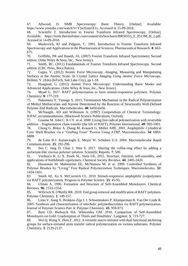
48
67. Allwood, D. NMR Spectroscopy: Basic Theory. [Online]. Available:
https://www.youtube.com/watch?v=T3scEom1E1s. Accessed in 15-09-2018.
68. Scientific T. Introduction to Fourier Transform Infrared Spectroscopy. [Online].
Available: https://tools.thermofisher.com/content/sfs/brochures/BR50555_E_0513M_H_1.pdf.
Acessed in 14-09-2018.
69. Markovich, RJ and Pidgeon, C. 1991. Introduction to Fourier Transform Infrared
Spectroscopy and Applications in the Pharmaceutical Sciences. Pharmaceutical Research. 8: 663-
675.
70. Griffiths, PR and Haseth, JA. (2007) Fourier Transform Infrared Spectrometry Second
edition. (John Wiley & Sons, Inc., New Jersey).
71. Smith, BC. (2011) Fundamentals of Fourier Transform Infrared Spectroscopy. Second
edition. (CRC Press, Boca Raton).
72. Gupta, V. (2012) Atomic Force Microscopy -Imaging, Measuring and Manipulating
Surfaces at the Atomic Scale. In Crystal Lattice Imaging Using Atomic Force Microscopy,
Bellitto, V. (Eds) (InTech, Salt Lake City), pp 1-18.
73. Haugstad, G. (2012) Atomic Force Microscopy: Understanding Basic Modes and
Advanced Applications. (John Wiley & Sons, Inc., New Jersey).
74. Moad G. 2017. RAFT polymerization to form stimuli-responsive polymers. Polymer
Chemistry. 8: 177-219.
75. Nakamura Y. Yamago S. 2015. Termination Mechanism in the Radical Polymerization
of Methyl Methacrylate and Styrene Determined by the Reaction of Structurally Well-Defined
Polymer End Radicals. Macromolecules. 48: 6450-6456.
76. McNaught, AD and Wilkinson A. (1997) Compendium of Chemical Terminology:
IUPAC recommendations. (Blackwell Science Publications, Oxford).
77. Graeme M. John C. K CY. et al. 2000. Living free radical polymerization with reversible
addition – fragmentation chain transfer (the life of RAFT). Polymer International. 49: 993-1001.
78. Cheng G. Böker A. Zhang M. Krausch G. Müller AHE. 2001. Amphiphilic Cylindrical
Core−Shell Brushes via a “Grafting From” Process Using ATRP. Macromolecules. 34: 6883-
6888.
79. de Gans B-J. Kazancioglu E. Meyer W. Schubert U.S. 2004. Macromolecular Rapid
Communications. 25: 292-296.
80. Seo C. Jang D. Chae J. Shin S. 2017. Altering the coffee-ring effect by adding a
surfactant-like viscous polymer solution. Scientific Reports. 7: 500.
81. Verduzco R. Li X. Pesek SL. Stein GE. 2015. Structure, function, self-assembly, and
applications of bottlebrush copolymers. Chemical Society Reviews. 44: 2405-2420.
82. Husseman M. Malmström EE. McNamara M. et al. 1999. Controlled Synthesis of
Polymer Brushes by “Living” Free Radical Polymerization Techniques. Macromolecules. 32:
1424-1431.
83. Smith AE. Xu X. McCormick CL. 2010. Stimuli-responsive amphiphilic (co)polymers
via RAFT polymerization. Progress in Polymer Science. 35: 45-93.
84. Ulman A. 1996. Formation and Structure of Self-Assembled Monolayers. Chemical
Reviews. 96: 1533-1554.
85. Willcock H. O'Reilly RK. 2010. End group removal and modification of RAFT polymers.
Polymer Chemistry. 1: 149-157.
86. Lima V. Jiang X. Brokken-Zijp J. J. Schoenmakers P. Klumperman B. Van Der Linde R.
2005. Synthesis and characterization of telechelic polymethacrylates via RAFT polymerization.
Journal of Polymer Science Part A: Polymer Chemistry. 43: 959-973.
87. Bain CD. Biebuyck HA. Whitesides GM. 2010. Comparison of Self-Assembled
Monolayers on Gold: Coadsorption of Thiols and Disulfides1. Langmuir. 5: 723-727.
88. Wei Q. Wang X. Zhou F. 2012. A versatile macro-initiator with dual functional anchoring
groups for surface-initiated atom transfer radical polymerization on various substrates. Polymer
Chemistry. 3: 2129-2137.

49
Appendix
Appendix A - Purified 6th PHEMA achieve using RAFT polymerization
Appendix B - Solvent table for different synthesised PHEMA is displayed: The concentration test
of the solubility test was:10 mg/mL. In the case of undissolved PHEMA, the concentration was
diluted further to 10mg/ml+5ml.
Good solvent: Dissolved
Bad solvent: Anything but a
one-phase solution
1st PHEMA (51 kDa) 3rd PHEMA (19 kDa)
Acetone Bad solvent Bad solvent
Methanol Good Solvent Good Solvent
Iso-propanol NA Good Solvent
Water Bad solvent Bad solvent
DMF Good Solvent Good solvent
DMSO Good Solvent Good solvent
Chloroform Bad solvent Phase separation
Diethyl ether Bad solvent Bad solvent
THF Bad solvent Bad solvent
Toluene Bad solvent Phase separation

50
a
b
c
Appendix C - Purified PBIEM-B.
Appendix D – Pyridine NMR
a
b
c
HDO

51
Appendix E - Solvent table for different fabricated PBIEM is shown: The concentration test of
the solubility test was the same as the solubility test for PHEMA.
Good solvent: Dissolved
Bad solvent: Anything but a
one-phase solution
PBIEM-A PBIEM-B
Acetone Good solvent Good solvent
Acetonitrile Bad solvent NA
Methanol Bad solvent Bad solvent
Iso-propanol Didn’t dissolve completely NA
Water Bad solvent Bad solvent
DMF Good solvent Good solvent
DMSO Good solvent Good solvent
Chloroform Good solvent Good solvent
N-hexane Bad solvent Bad solvent
Diethyl Ether Bad solvent Bad solvent
THF Bad solvent Dissolved partially
Toluene Didn’t dissolve completely Didn’t dissolve completely
Ethylene glycol Bad solvent Bad solvent

52
Appendix F – AFM step height determination.
Appendix G- Inks produced and shown in the work. 1st setup: PBIEM-A 10% in DMF (left side);
PBIEM-A 0.5% in acetone (right side).
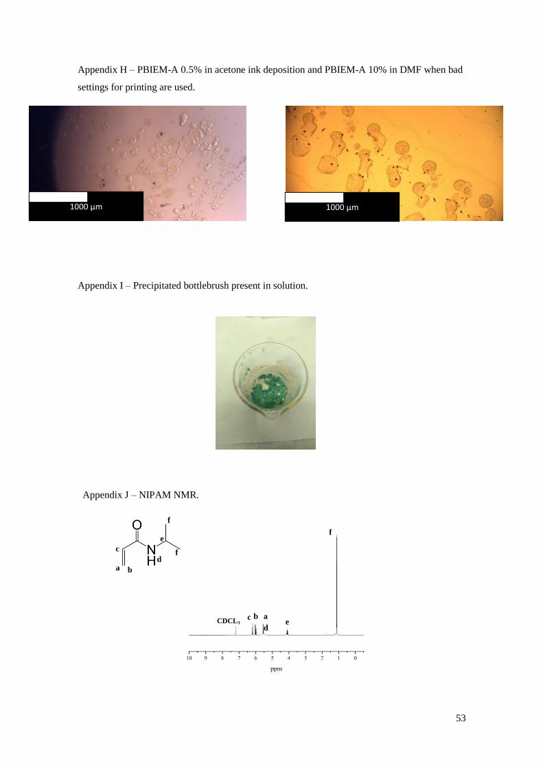
53
a b
c
d
e
f
f
Appendix H – PBIEM-A 0.5% in acetone ink deposition and PBIEM-A 10% in DMF when bad
settings for printing are used.
Appendix I – Precipitated bottlebrush present in solution.
Appendix J – NIPAM NMR.
b a c
d e
f
CDCL3
1000 μm 1000 μm
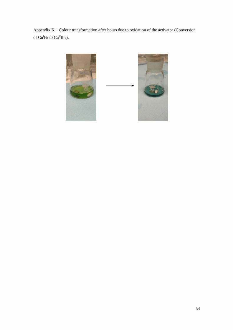
54
Appendix K – Colour transformation after hours due to oxidation of the activator (Conversion
of CuIBr to CuIIBr2).