special print control valve design aspects for critical ... · valve coefficient cv value and the...
TRANSCRIPT

Control valve design aspectsfor critical applicationsin petrochemical plants
Special print from„Valve World“ June 2004
By:Holger Siemers
SAMSON

Special print from „Valve World“, June 2004 3www.valve-world.net
With three decades of experience in demanding applications, MrSiemers has a deep appreciation of developments and trends insizing control valves. In this paper, he reviews the past, presentand future of valve design and sizing, taking all-important issuessuch as increasing cost pressure and time pressure into account.This paper is presented in two parts: firstly, how to usemanufacturer independent software to analyze given orcalculated plant parameters in more detail from an overall pointof view with a complete power check and optimizingpossibilities. Some case studies are also discussed. The secondsection, scheduled for a future issue, includes information on todesign, size and use severe service control valves with goodperformance for long maintenance intervals. Differentphilosophies of valve design (plug design), pressure balancesystems, stem sealing, actuator sizing, cost philosophies for“high end” applications are discussed.
ership.End users increasingly complain about mainte-nance costs and the amount of spare parts re-quired which are often the highest after-salescost factors. Nowadays, the contradictionoften arises that consultants are under signifi-cant pressure to keep costs low and opt forother priorities:lowest cost of investmentjust meeting the specificationJust meeting the warranty timee-bidding and e-purchasing.
In the oil and gas market sector, many valvesare high power [�p x flow] converters and incombination with fluid corrosion and fluidcontamination the valve body and trim may beparts subject to wear.Time is often all-impor-tant during the initial phase involving the plan-ning, bidding and ordering of the controlvalves these days. Unfortunately, this results invalves being selected with a tremendous loss indetail engineering, yet at the same time, thetechnical responsibility has been shifted to the
The past, present and future of valvedesign and sizingControl valves - the workhorses of the controlloop - mostly have to convert to 1 to 5 kWheat power (the typical pump power in chemi-cal plants) and, furthermore, in the HPI sectorto a range between 5 to 200,000 kW heatpower - the typical power range with high per-formance pumps, flow machines or the totalplant power - blocked by flare shut-off valvesand control valves. From an economical pointof view, these valves often operate more orless successfully under high stress load, charac-terized by additional expenditure for noise-re-ducing insulation and devices or maintenance,or should severe problems arise, plant down-time, i.e. low or high cost of ownership.The following priorities concerning valves areoften specified by end users in the HPI sector:safety and reliabilitycontrol qualityenvironmental aspectstrouble-free life cycles and lowest cost of own-
valve manufacturer.Typical for urgent projects is that, to avoidpenalties, it is taken into account that somecontrol valves are destroyed during the start-up process even in large projects, whereasduring a traditional start-up process, a trou-ble-free commissioning is guaranteed by re-placing any critical valves with fittings andflushing the plant beforehand.A tremendousscope of difficulties can influence the project’ssuccess if planning mistakes are first detectedat this stage because the process condition cal-culations were too inaccurate or the controlvalve selection was “quick and dirty.” Ques-tions that arise here are: “who is responsiblefor plant safety?” and “has e-commerce (e.g. e-bidding and e-purchasing) taken place tooquickly for severe service control valves orvalves with key functions?”The shorter deci-sion time linked to anonymous bidding couldmean that key valve features such as plant safe-
Control valve design and sizing:
Part I
1. Accurate sizing & software tools
2. Energy saving by plant and valve
optimization
3. Debottlenecking: Can the old valve
do the new job ?
Part II
4. Predictable troubles with control valve
sizing in case of sub-critical flow
conditions and in case of flashing.
5. Control valve failures & troubleshooting.
6. The hidden valve enemy: Critical outlet
velocities need to take priority
Part III
7. Fugitive emissions philosophies for
control valves
8. Actuator sizing philosophies
9. Control valve design and cost philoso-
phies for “high end” applications
By Dipl. Ing. Holger Siemers, SAMSON AG
Control valve design aspectsfor critical applications in
petrochemical plants – part I

Special print from „Valve World“, June 20044 www.valve-world.net
ty, control quality and process long-term tar-gets are easily bypassed.From the valve manufacturer’s point of view,the situation is a challenge with regards to ful-filling both aspects concerning competitive-ness and reliability. Many well-known compa-ny brand names and their valve products aredisappearing or have merged to form largeconglomerates.The process of the “synergy ef-fect” continues more or less successfully. Itshould be clear that the chronicle of plant dis-asters will never cease, but the risk should notbe allowed to increase because valves intendedfor severe service are being sized and selectedin a “quick and dirty” fashion without involvingtime-consuming detail engineering.The ques-tion arises: can a happy medium be found tomeet the demands of both current and futureinterests? From experience gained from the increasingamount of troubleshooting required in petro-chemical plants and refineries over past fewyears, the conclusion that must be drawn isthat it is important to make sure that modernlightweight globe and rotary valves are onlychosen within their limited range of applica-tion. In the recent past, only heavy-duty valvessuch as high performance cage-guided or topand bottom guided globe valves fitted the totalrange of applications. For less severe applica-tions these were over-engineered. Pressure toreduce costs meant that this valve generationwas replaced in the lower application field bylightweight, inexpensive valves. Low and highperformance butterfly valves and other quar-ter-turn products have been developed fortypical market segments.Rotary plug valves can save costs when theyreplace globe valves, but there is also a risk ifengineering competence for critical applica-tions is missing.Time and effort must be spentmeasuring new valve products on test rigs be-fore they can be launched onto the market.Operating data limits above test rig possibili-ties are often detected by troubleshooting ex-
periences or trial-and-error methods.Typicalvalve characteristics have to be published asstipulated in international standards like theEN IEC 60534.The individual measurementsof the actual valve factors or their approxima-tions are stored in in-house software of com-petent valve companies.Cavitation and flashing combined with the in-fluence of the valve outlet velocity of pure liq-uid or liquid/vapor phase can cause severetrouble and, in the worst case, cause plantshutdown. Some experiences in this area arepublished in Chapter 6.Most potential problems can be predicted byusing highly sophisticated software when theoperating limits are known and the load-spe-cific valve characteristics cv, xFz, Fl, xT, Fd areprovided by the valve companies.Warning in-dicators can be activated to indicate a point ina selected system of valves and pipeline wheremechanical overload occurs due too high ve-locities or forces or where the noise level doesnot comply with the stipulated requirements.
1. Accurate Sizing & Software ToolsThe CONVAL® 6 software treats the plant andvalve sizing parameters from an overall pointof view, issuing dynamic graphics with in-stalled characteristics concerning flow, power,gain and outlet velocity as a function of thevalve coefficient cv value and the valve travel.The software is a manufacturer independent
optimization tool for pipelines and pipe de-vices (Figure 2a), including material and prop-erty database for more than 1,000 substancesincluding hydrocarbons. Ethylene, propylene,chlorine, natural gas AGA 8 and sixty other in-dustrial fluids are calculated very accuratelyusing equations of state developed by the RuhrUniversity of Bochum (see www.conval.de formore details).If operating conditions are given with one, twoor three operating points the plant system isdefined in the standardized differential pres-
Fig. 1: Calculating installed
valve characteristic schemes.
�p versus flow and Flow;
Cv versus travel.
Fig. 2a: CONVAL Tool description.
Tool for sizing, calculation and optimization of common plant components:
• Control valves • Steam conditioning valves • Actuator forces • Differential pressure flow elements • Restriction orifice plates • Safety relief valves • Tank depressurization • Pressure loss • Pressure surge • Pipes:
• Sizing • Pipe compensation • Span calculation • Pipe wall thickness
• Shell-and –tube heat exchanger • Condensers • Pump motor output
Supported by vendor independent device databases(control valves, safety relief valves), fluid property calculation, material databases, …

Special print from „Valve World“, June 2004 5www.valve-world.net
sure versus flow diagram at the left-hand side(see Figure 1).The inherent cv-characteristicof any valve as well as all other valve character-istics xFz, Fl, xT, Fd, a.s.o. are stored in a largevalve data base in the form of equations orpolynomial coefficients. Every valve installedcharacteristic like flow, gain and valve authori-ty, sound, inlet and outlet velocity, as well ascavitation, flashing, and choke flow areas arepresented in graphic form on the right-handside.A dynamic ruler publishes all results in-cluding alarms and hints at any valve travel po-sition.The program combines expert valve siz-ing with powerful plant optimization and trou-ble shooting.The software provides a bi-directional COMlink to spreadsheets and CAE systems ( Figure2b) as well as in-house valve sizing programs(Box 1) which companies can use to storevalve data e.g. sound measurements, adminis-tration of inquiry and quotation systems aswell as pricing and drawings.
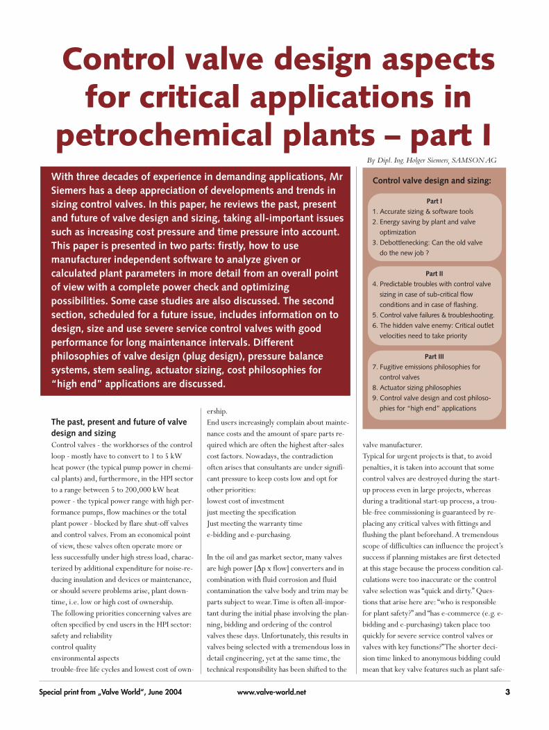
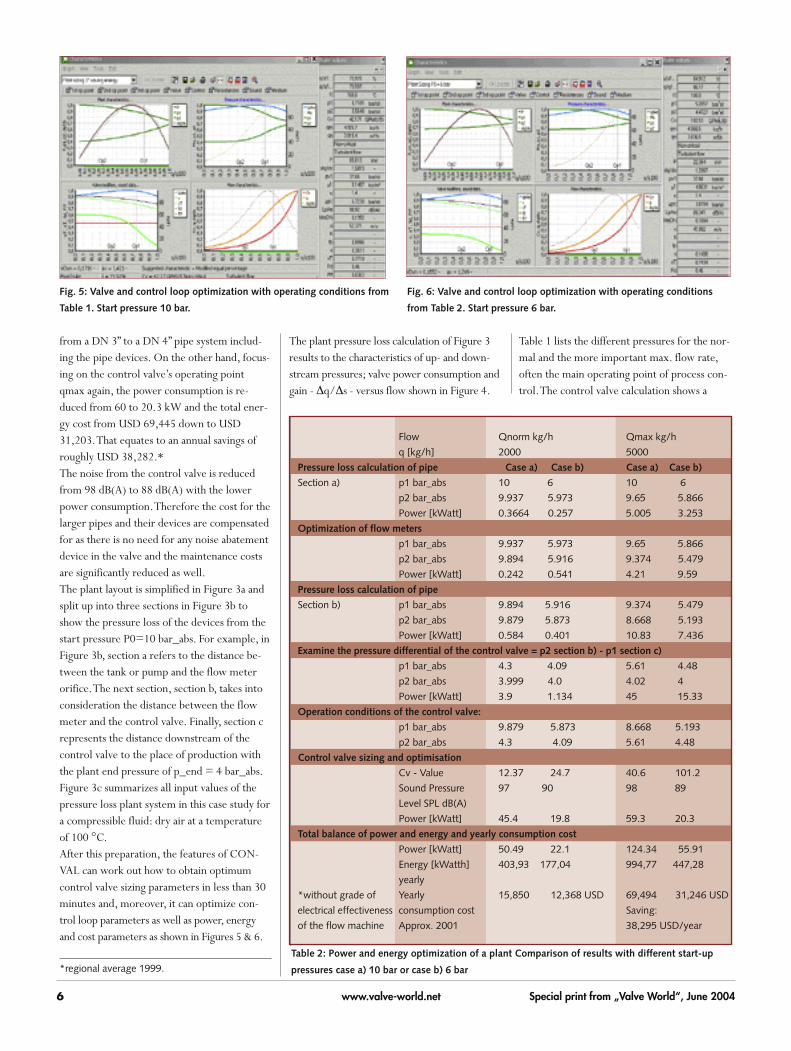
2) Energy saving by plant and valveoptimizationThe first case study shows many aspects ofplant optimizing and presents methods to ob-tain the most important parameters for controlvalve sizing at two or, even better, three operat-ing points.An exceptional amount of over 50% of power and costs could be saved if plantdesign, pipes and pipe devices such as controlvalves were to be sized more rationally.[1] Lower power consumption of control valves re-duces the cost of investment by using standardvalve series without noise abatement devices andincreases the life cycle because of the reducedamount of wear of the throttling valve parts.Saving energy means recalculating our figureswith a lower start pressure of p0 = 6 bar andoptimizing the pipeline and all the pipe de-vices.The result is, on the one hand, a change
2 1 )
)
Fig. 3b: Same plant layout, split into three sections to show
pressure losses.
Fig. 3a: Typical plant layout (simplified) in a chemical or
petrochemical plant. Fig. 3c: Input values of the pressure loss plant system.
Pressure
Fig. 4: Case study 1 -
pressure/flow
diagram with
additional data on
valve power and gain
characteristic.
Special valve manufacturer software is
available and is mainly used for proprietary
control valve series and their special demands.
Programs can store several thousand pieces of
valve data like cv characteristics, noise data
and noise correction measurements and
related functions of valve recovery factors
based on flow lab data. Specific actuator
sizing or special sizing methods for mixtures
and the flashing outlet conditions are available
as well as having links to quotations, pricing,
drawing software and to the production units.
Figure 2b: The
following CAE
tools provide a
bi-directional
interface to
CONVAL® 6.0:
1) Reference to CAE interface list 2) e.g. SAMSON valve sizing application
C O N V A L
.N E T C lie n t A p p lica tio n
C O M In te rfa c e.N e t In te ro p
a sse m b ly
.NE
T
C O M C lie n t A p p lica tio n
CO
M
C O M C lie n t In te rfa ce
CO
M
Exce
l E
xpo
rt
PD
F E
xp
ort
MA
PI
Clie
nt
(Em
ail)
Na
tiv
e l
ink
C lie n t A p p lic a t io n
Na
tive
CO
NV
AL
file
s
F i le F ile F ile F ile
E x c e l
A c c e s s
W o rd
P ro g a m m in g
la n g u a g e s
C A E
S y s te m s(1 )
V e n d o r
p ro g ra m s (2 )
P ro g a m m in g
lan g u a g e s
.. .
. ..
. ..
Box 1: In-house valve sizing program
Special print from „Valve World“, June 20046 www.valve-world.net
from a DN 3” to a DN 4” pipe system includ-ing the pipe devices. On the other hand, focus-ing on the control valve’s operating pointqmax again, the power consumption is re-duced from 60 to 20.3 kW and the total ener-gy cost from USD 69,445 down to USD31,203.That equates to an annual savings ofroughly USD 38,282.*The noise from the control valve is reducedfrom 98 dB(A) to 88 dB(A) with the lowerpower consumption.Therefore the cost for thelarger pipes and their devices are compensatedfor as there is no need for any noise abatementdevice in the valve and the maintenance costsare significantly reduced as well.The plant layout is simplified in Figure 3a andsplit up into three sections in Figure 3b toshow the pressure loss of the devices from thestart pressure P0=10 bar_abs. For example, inFigure 3b, section a refers to the distance be-tween the tank or pump and the flow meterorifice.The next section, section b, takes intoconsideration the distance between the flowmeter and the control valve. Finally, section crepresents the distance downstream of thecontrol valve to the place of production withthe plant end pressure of p_end = 4 bar_abs.Figure 3c summarizes all input values of thepressure loss plant system in this case study fora compressible fluid: dry air at a temperatureof 100 °C.After this preparation, the features of CON-VAL can work out how to obtain optimumcontrol valve sizing parameters in less than 30minutes and, moreover, it can optimize con-trol loop parameters as well as power, energyand cost parameters as shown in Figures 5 & 6.
Fig. 5: Valve and control loop optimization with operating conditions from
Table 1. Start pressure 10 bar.
Fig. 6: Valve and control loop optimization with operating conditions
from Table 2. Start pressure 6 bar.
The plant pressure loss calculation of Figure 3results to the characteristics of up- and down-stream pressures; valve power consumption andgain - �q/�s - versus flow shown in Figure 4.
Table 1 lists the different pressures for the nor-mal and the more important max. flow rate,often the main operating point of process con-trol.The control valve calculation shows a
*regional average 1999.
Flow Qnorm kg/h Qmax kg/h
q [kg/h] 2000 5000
Pressure loss calculation of pipe Case a) Case b) Case a) Case b)
Section a) p1 bar_abs 10 6 10 6
p2 bar_abs 9.937 5.973 9.65 5.866
Power [kWatt] 0.3664 0.257 5.005 3.253
Optimization of flow meters
p1 bar_abs 9.937 5.973 9.65 5.866
p2 bar_abs 9.894 5.916 9.374 5.479
Power [kWatt] 0.242 0.541 4.21 9.59
Pressure loss calculation of pipe
Section b) p1 bar_abs 9.894 5.916 9.374 5.479
p2 bar_abs 9.879 5.873 8.668 5.193
Power [kWatt] 0.584 0.401 10.83 7.436
Examine the pressure differential of the control valve = p2 section b) - p1 section c)
p1 bar_abs 4.3 4.09 5.61 4.48
p2 bar_abs 3.999 4.0 4.02 4
Power [kWatt] 3.9 1.134 45 15.33
Operation conditions of the control valve:
p1 bar_abs 9.879 5.873 8.668 5.193
p2 bar_abs 4.3 4.09 5.61 4.48
Control valve sizing and optimisation
Cv - Value 12.37 24.7 40.6 101.2
Sound Pressure 97 90 98 89
Level SPL dB(A)
Power [kWatt] 45.4 19.8 59.3 20.3
Total balance of power and energy and yearly consumption cost
Power [kWatt] 50.49 22.1 124.34 55.91
Energy [kWatth] 403,93 177,04 994,77 447,28
yearly
*without grade of Yearly 15,850 12,368 USD 69,494 31,246 USD
electrical effectiveness consumption cost Saving:
of the flow machine Approx. 2001 38,295 USD/year
Table 2: Power and energy optimization of a plant Comparison of results with different start-up
pressures case a) 10 bar or case b) 6 bar

Special print from „Valve World“, June 2004 7www.valve-world.net
xFz_cage
xF
Fig. 10: Case study 2: Calculation of the cage retained seat valve with max. SPL
[LpAa] > 91 dB(A).
Fig. 11: Case study 2: Sizing of the existing cage valve with multi-hole baffle to
reduce the noise from 91 to 85 dB(A).
power consumption of 60 kWatt and a predict-ed sound pressure level SPL of 98 dB (A).
Flow q kg/h 2000 5000Pressure p1 bar_abs 9.879 8.668Pressure p2 bar_abs 4.3 5.61
Table 1: Control valve optimization from an
overall point of view.
3. Debottle-necking: can the old valvedo the new job?When looking to increase the productivity ofan existing plant, engineers have to take con-trol valves into account.This second case studyfor an existing application to control a liquidmedium flow presents the troubleshootingmeasures to increase a plant’s productivity tomeet current market demands.This example looks at an existing 8” cage valve(Figures 7 and 8) optimized for 85 dB (A) withan additional multi-hole baffle (Figure 12) andprovides an easy method to obtain new valveparameters without having to start a newtime-consuming total plant pressure loss cal-
305t/h 380t/h
�p100
�p 0 old
new Rule of thumb for plant designers:
keep a min. pressure differential for
control valves with equal percentage
characteristics.
Flow 100 % �p100/ �p 0 = 0.1
Flow 90 % �p 90/ �p 0 = 0.27
Flow 80 % �p 80/ �p 0 = 0.42
Fig. 7: Case study 2: The old specification data.
Fig. 8: Case study 2: The old 8” cage pressure-
balanced control valve.
Fig. 9: Case study 2: Old and new upstream pressure line to increase the flow.

Special print from „Valve World“, June 20048 www.valve-world.net
culation.At least with just one more powerful pump the new operat-ing point can be kept controllable. However, severe cavitation in-creases the noise to 96 dB (A) with the existing control valve.Theunique new development of an anti-cavitation trim “AC Trim System”can solve cavitation problems and reduce the sound < 85 dB (A)within the entire control range (see Chapter 5).The software provides the user with new calculation methods includ-ing graphic supports to help check the control valve performance aswell as leading to the most economic solution to reduce noise (Fig-ures 9, 10 and 11).The question arises: can the existing control valve be updated takingnoise limitation of 85 dB(A) into account ?The case study is based on a real situation where the productivity hadto be increased, while keeping the noise level (SPL) within the exist-ing regulations. If the old DN 8” valve just fulfilled the noise require-ments of 85 dB(A) by using a baffle or silencer, then the solution forthe revised valve presents a real challenge.
The cage retained seat valve has been operating for some five yearswithout complaints, but cannot be used after debottle-necking tocontrol 30% more flow because of increasing sound-pressure-level >95 dB(A).The new pump-impeller increases the power to such alevel that there is no economic solution available with the old valve.Fortunately the development and research program of SAMSON AGhas presented the unique anti-cavitation AC Trim System.This fulfilsthe 85 dB(A) requirement and replaces the existing cage trim design(Figures 13 and 14).
Successful debottle-necking after increasing the pumppower (Figure 15)The new pump impeller increases the plant upstream pressure andthe power and noise as well.The old cage valve now generates 96dB(A).There is no chance to keep the low noise level with the exist-ing valve.The new valve with AC Trim System shows no cavitation atthe operating point 380t/h 65 dB(A) and less cavitation < 85 dB(A)in the entire range of control. �
Fig. 12: Case study 2: Calculation and construction of downstream
resistance structures like single and multi-baffles.
Fig. 13: Case study 2: CFD optimization of anti-cavitation trim design -
computer flow simulation. Shown is SAMSON’s AC Trim I System
Parabolic plug top and seat guided. Seat and plug CFD optimized.
Fig. 14: Case Study 2: AC Trim System. The result of flow research (patent
pending) Natural low noise, dirt and vibration insensitive. Top and seat
guided low noise parabolic trim, no risk of stroke blocking.
Fig. 15: Case Study 2: Sound optimisation for < 85 dB(A) noise limit
with the unique AC Trim System and highest xFz characteristic of
control valves today.

Special print from „Valve World“, June 2004 9www.valve-world.net
Control valve design aspectsfor critical applications in
petrochemical plants – part II4) Predictable troubles with controlvalve sizing in case of sub-critical flowconditionsIt is well-known that sensitive valve sizingareas exist with supercritical gases and slightlysub-cooled or non-sub-cooled liquids (flash-ing).Vapors and gases are calculated with theisentropic exponent k as one of the propertyvalues. Some hydrocarbons, e.g. ethylene, arenear or above the “critical points t_ crit. andp_crit.” during the process.
By Dipl. Ing. Holger Siemers, SAMSON AG
Critical flow
Predictable
control instability,
if application data are near the
critical
point because of sudden change
of density and isentropic
exponent.
Not critical flow
Incorrect result:
Cv calc = 81
xT = 0.2
at operating
point
wrong �=1.2
Correct result:
Cv calc= 59 with
���� = 5.6 !
Range of ���� from
p1 = 60 to 70 bar and
t1 from
12 to 16 °C
Fig. 16: Sensitive sizing areas in case of supercritical flow “isentropic
exponent above the critical point” > 2
This second section of Mr Holger Siemers article on controlvalve design and sizing continues on from part I, which can befound in the June 2004 issue of Valve World. This sectionpresents information on design, size and use of severe servicecontrol valves, the kind of troubles that can be predicted withcontrol valve sizing as well as suggestions for troubleshootingcontrol valve failures. The final section, part III, will be readyand waiting in the upcoming October issue.

Special print from „Valve World“, June 200410 www.valve-world.net
The sizing standard IEC 60534 2-1 includes aninformation table with typical isentropic expo-nents used for steam and gas sizing.The totalrange 1 < k < 2 is well-known for all com-pressible fluids. However, it is less-well-knownthat values 2 < k < 20 exist with supercriticalfluids near and above the property criticalpoint.
We would like to introduce this matter withthe help of latest development in precise prop-erty calculation, published at the Ruhr Univer-sity of Bochum for more than 60 industrialgases and integrated into theCONVAL“ software.The third case study shows tremendous sizingdifferences in flow calculation for an ethylene
application at the critical point of propertiesby using the real isentropic exponent >> 2.This can have a negative influence on plantsafety valves and other devices. In the past, de-vices for supercritical flows were oversized be-cause the wrong isentropic exponents and“choked flow limits” were used.We are inter-ested to start an open discussion on how to de-fine and handle this phenomenon and on howto validate it with measurements.
1)*Red area: Planning error: Loss of control quality at operating point qmax, see Fig. 18 Valve authority too small to control qmax related to: SHELL DEP 32.36.01.17.-GEN 2)*Red area: Selection error Flashing with outlet velocities > 60 m/s, risk of mechanical damage, pipe vibration. Larger DN is recommended, if control < Op2 3)Light red area: cavitation start if xF > xFz 4)Red area: choked flow, max. cavitation or flashing start, if xF >Fl²
Table 3: Available substances calculated with thermodynamic equations
1-Butene
Air
Ammonia
Argon
Benzene
Butane
Carbon
monoxide
Carbon dioxide
Chlorine
Cyclohexane
Cyclopentan
Cyclopropan
Decane
Diethylether
Diisopropyl
Dipropylether
Ethane
Ethylbenzol
Ethylene
Fluorine
Helium
Heptane
Hexane
Hydrogen
Hydrogensulphi
de
Isobutane
Isohexan
Isopentan
Krypton
Methane
Methanol
Natural gas
(AGA8)
Neon
Neopentan
Nitrogen
Nitrous oxide
Nonane
Octane
Oxygen
Pentane
Phenol
Propane
Propylbenzol
Propylene
SF6
Toluene
Water
Xenon
R11
R113
R12
R123
R124
R125
R134a
R141b
R142b
R143a
R152a
R218
R22
R23
R32
R41
*Red area: Planning error leads to reduced control quality at operating point qmax Valve authority Vdyn too small to control qmax: CONVAL red area alarm if: Vdyn = dp_q90 / dp_0 < 0,27; qmax > 0,9q_100 Input of one to three operating points. Illogical characteristics can be corrected by picking up an operating point and shifting the point to the logical place. This helps to avoid time-consuming plant system pressure loss calculations. The red area shows here that Op. 1 is near the max. plant system flow –short circuit performance- and the valve pressure drop
Fig. 19: Typical damage due to cavitation if
pressure differential > 20 bar. Feedwater control
valve mismatched for start-up 70 to 1 bar.
Fig. 20: Damage due
to flashing if p2 << pv
and v2 >> 60 m/s.
Fig. 21: Damage due to a rotary plug body due
to cavitation v2 >> 5 m/s.
Fig. 22:
Damage
due to
steam
pressure
letdown
Ma >> 1.
Fig. 17: Example of warning indicators in a hot water application to indicate the onset of cavitationand flashing at smaller loads. If not controlled below Op2 no risk, if often control smaller loads < Op2, valve DN too small.
Fig. 18: Dynamic plant system: – pressure versus flow-*Red area: Planning error: Loss of control quality at operating point qmax. Valve authority toosmall to control qmax. Optimised, following: SHELL DEP 32.36.01.17.-GEN (Design andEngineering Practise)
Vdyn= �p_q90 / �p_0 < 0,27;qmax > 0,9q_100

Special print from „Valve World“, June 2004 11www.valve-world.net
Predictable troubles with control valvesizing in case of flashing as well as in-stallation cost saving which results inpoor planning parametersFigure 17 shows an example of warning indi-cators in a hot water application to indicate theonset of cavitation and flashing at smallerloads. If not controlled below Op2 no risk, ifoften control smaller loads <Op2, valve DNtoo small.
CONVAL calculates real thermodynamicflashing conditions with about sixty hydrocar-bons [see Table 3] and recommends the mini-mum valve DN to avoid critical outlet veloci-ties.The calculations resemble steam tablemathematics.This is based on a reliable source,
the “Lehrstuhl für Thermodynamik Fakultätfür Maschinenbau der Ruhr-UniversitätBochum”www.ruhr-uni-bochum.de/themo/index-eng.htm
Installation cost saving which resultsto poor planning parametersDetecting planning mistakes: qmax > 0.9q100,�p at qmax too small. See Figure 18.
5) Control valve failure and troubleshooting.Ranging from seat guided V-port to CFD opti-mized trims and their applications.There aredifferent solutions to avoid critical sound andmechanical valve failure (see Figures 19through 22).This section introduces anti-cavi-tation valve trim designs [2] and noise attenua-
Flow divider STR I
Flow divider STR III Silencer with multi-hole baffles Low noise valve, STR III + Silencer
Fig. 23: The simplified noise abatement system used for compressible fluids.
Fig. 25: AC Trim II System
High �p at qmax
High �p at qmin
Low �p at qmax
High �p at qmin
Application with:
Low �p at qmax
High �p at qmin
3 2 5 1 4 " w ith S p e c ia l P a ra b o lic P lu g C v s 1 2 0 e q p . (S e a t d ia m e te r 1 0 0 m m )
C o m p a r is o n o f T e s t a n d S iz in g R e s u lts (p 1= 7 .5 5 b a r (a ), p v= 0 .5 1 b a r (a ) )
3 0
4 0
5 0
6 0
7 0
8 0
9 0
0 0 ,1 0 ,2 0 ,3 0 ,4 0 ,5 0 ,6 0 ,7 0 ,8 0 ,9 1x F [- ]
Lp
e,a
[d
B(A
)]
In te rn a l n o is e te s t C v = 8 3P re d ic t io n C v = 8 3In te rn a l n o is e te s t C v = 7 5P re d ic t io n C v = 7 5In te rn a l n o is e te s t C v = 1 6P re d ic t io n C v = 1 6
3251 DN 100 PN 40
Sb 100 AC II trim 1990-0293
Seat with 3 integrated baffles 1990-0293
55
60
65
70
75
80
85
0 0,2 0,4 0,6 0,8 1
xF
Lp
A,a [
dB
(A)]
Aussenmessung kv 54
Aussenmessung kv 40
Aussenmessung kv 30
Aussenmessung kv 20
Aussenmessung kv 10
p1=11bar
p1 [bar] 11 11 11
p2 [bar] 4 4 4
pv [bar] 0.01 0.01 0.01
Q [m^3/h] 30 108 144
rho [kg/m^3] 835 835 835
kv ges [m^3/h] 10.36 37.3 49.73
Lp [dB(A)] < 70 < 70 < 70
xF 0.64 0.64 0.64
Application with:
High �p at qmax
High �p at qmin
Globe valve type
XFz for valve 75% load
XFz for valve << 75% load
Resistance to con-tamination
Vibration be-havior
Parabolic plug 0.25 to 0.35 clearly up to 0.8
high poor for single-guided plugs
Piston-balanced plug with cage
0.25 to 0.35 up to 0.5 low good
V-port plug 0.25 to 0.35 up to 0.5 high excellent
Perforated plug 0.25 to 0.35 0.25 to 0.35 low good
AC Trim System
0.35 to 0.5 clearly up to 0.85
high good
Fig. 26: Case history: application with low �p
at qmax and high �p at qmin.
Troubleshooting for an acetic acid plant,
replaciong a noisy cage valve >> 85 dB(A) at
a petrochemical plant in Hull (UK) with an AC
Trim I System. The requirements were to
avoid cavitation in the range of control in
case of corrosive fluids. XFz > 0.75 at critical
min. flow.
Fig 27: Case history: application with high �p
at qmax and high �p at qmin.
Troubleshooting for a gasoline loading
station at a refinery in Hamburg (Germany)
with AC Trim II System and the requirement
to reduce SPL > 90 dB(A) to < 70 dB(A) in the
entire range of control. XFz > 0.75 in the total
range of control.
Fig. 24: AC Trim I System.
Table 4: Different trim designs and their advantages and disadvantages in severe service
applications.
AC Trim I System
Application with:
Low �p at qmax
High �p at qmin
Start up pointat qmin.
AC Trim II System
Application with:
Low �p at qmax
High �p at qmin

Special print from „Valve World“, June 200412 www.valve-world.net
tion devices and discuss their advantages anddisadvantages as well as their application limits.Note that too high velocities at the valve mov-ing parts and at valve outlet are mainly responsible for valve failure especially wherecorrosive fluids are handled.
SAMSON AG offers under strong limitationsof valve outlet velocities and other parametersthe high performance V-port trim for generalservice; flow dividers I and III and downstreamlow noise devices for gas and steam pressureletdown. See Figure 23.If the V-port trim sound pressure level (SPL) isnot acceptable for liquid applications or cavita-tion and corrosion must be avoided in general,the unique AC Trim System is recommended(see Figures 24 and 25) with top and seat guid-ed plug; it is vibration-free and dirt-insensitive.The max. pressure differential 25 to 40 bar de-pends on the fluid properties. For case histo-ries of troubleshooting with the AC Trim sys-
tem , please see Figures 26 and 27. Further,Table 4 gives an overview of the advantagesand disadvantages of different trim designs.
AC Trim III system multistage designThe AC Trim III System is ideal for liquid application to avoid cavitaion, wear and noise(see Figuire 28). Features include top and seatguided plug, vibration free and dirt-insensi-tive, with/without pressure balance, pressuredfferential 25 up to 120 bar;AC Trim V Sys-tem-5 stages-120 bar < �p <200 bar. Threeand five stages in the cv range from Cv =1 (3stages) to Cv=116 from DN 1 to DN 6 inchin globe and angle type valves are used in caseof severe cavitation problems e.g. high �p to-gether with a larger control range qmin toqmax.Typical applications are feed-waterstart-up valves, refinery valves, snow gunvalves, injection valves, boiler applications,high pressure letdown service, etc.
6) The hidden valve enemy: Criticaloutlet velocities need to take priorityBeating “quick and dirty” sizing philosophies, ifselecting too small valve DN taking only thecalculated Cv value into account. High flowcapacity valves (Cv/DN2 ) need to be selectedwith care when critical operation conditionsare involved. Rule of thumb to avoid mixphase flow: in case of pv equal or near to p1avoid 20xDN any pipe restriction at valve up-stream, no elbows, no manual valves, no pipereducers.Sensitive sizing areas special valve DN selec-tion by giving priority to the outlet velocitycondition of cavitation and flashing in liquidapplication and gas and steam pressure let-down, taking important piping parametersinto account.
In case of flashing conditions, the average out-let velocity has to be calculated for the mix-ture of liquid and wet steam or vapour. Severepipe vibration and valve damage can be avoid-ed if the valve outlet diameter restricts theoutlet velocity to less than 60 m/s (average of0.7 Ma of mixture sonic speed). SAMSON hasdeveloped equations of state for flashing outletvelocities used in CONVAL for all fluids inTable 3. �
To be continued.
Valve design KC ����pcrit,cav
[bar]
Single-stage globe valves with stellited or hardened valve plug and seat
0.7 25
Single-stage globe valves with standard materials 0.7 15
Rotary plug valves (with eccentric spherical disk) 0.4 10
Butterfly and ball valves 0.2-0.3 5
Fig. 29: Flashing Photo SAMSON AG test rig [2]
Fig. 30: The thermodynamic flashing process. T = temperature; s = entropy; K = critical point.
Fig. 31: Plant shutdown due to “quick and
dirty” sizing with 8 inch rotary plug valve and
too small DN.
Non-subcooled naphtha p1 = pv.
The application requires a 12 inch valve to
avoid the risk of sonic speed “choked flow” at
the valve outlet.
Table 5: Recommendations to reduce cavitation erosion [2]. Using table 5 for non-corrosive liquids
with cavitation: XF>XFz
• Outlet velocity should not exceed 2m/s to max 5m/s depends on valve design
• Low vibration valve plug design like seat, cage or top and bottom guided plugs.
• Low cavitation erosion: �p < KC • (p1-pv) or �p < �pcrit,cav , if �p > KC • (p1-pv) !
• Cavitation erosion: �p > KC • (p1-pv) and �p > 25 bar -> multistage globe valves
(like AC Trim III System)
Fig. 28: AC Trim III System.
2-phase flow at outlet conditionThermodynamic throttling process

Special print from „Valve World“, June 2004 13www.valve-world.net
Control valves can be components of high dy-namic processes with most valves controllingto a set point. Hence they move around theoperating point, with the valve stroke moving
Control valve design aspectsfor critical applications in
petrochemical plants – part III
7) Fugitive emissions philosophies forcontrol valves It is interesting to compare the use of the bel-lows seal design versus low emission packingmaterial.The bellows seal design seems tohave been forgotten in international discus-sions and published papers, but it is still un-beatable as regards its life cycle and tightnessquality. In the “world of valves” under the re-quirements of fugitive emissions approximate-ly 5% are control valves.This means about 95% valves are on-off de-vices like gate, cock or ball valves. Most often,they remain static in the open or closed posi-tion. Only a very small percentage are cycledor part of a dynamic process. For the majorityof on-off valves that are equipped with bellowsseal, the bellows are designed only for somethousands cycles.
within less than twenty per cent of the totaltravel.Very occasionally they “sleep”.Here, certified fugitive emission packing ma-terial and design is sophisticated, but because
By Dipl. Ing. Holger Siemers, SAMSON AG
Core competence in manufacturing bellows seal:Depth of the welding seams
The bellows
geometry
Metal bellows seal
Tolerable number of spans for
SAMSON stem tightening elements
0,1
1
10
100
0 10 20 30 40 50 60 70 80 90 10
Double amplitude [%]
To
lera
ble
nu
mb
er
of
sp
an
s in
[m
illio
ns]
SAMSON tests (bellows seal)
Approximation (bellows seal)
PTFE packing
Graphite packing
Test connection Pressure switch for alarm signal
the dimensions and penetration depth of the welding
Fig. 7.3 Life cycle comparison
Tightness
Low-emission packing
Tightness
Bellows seal
Life cycle
Life cycle
�V-Ring design �PTFE-carbon compound �Spring loaded �Min. maintenance�Low-emission (10
-5 mbar l/sec)
�Temperatures up to 220°C �Over-tightening of the packing is not possible
Fig. 32: Standard stuffing box design
Fig. 33: Precise production of the bellows
geometry seams is assured by testing macro
sections. Fig. 34: Life cycle comparison
Fig. 35: Life cycle comparison in chemical plants with PTFE/graphite packing and bellows seal

Special print from „Valve World“, June 200414 www.valve-world.net
of the small production volume, expensive.Furthermore, the material loses its predictedlife cycle time in hazardous environments, i.e.its sealing quality.Attacks from within the valve, e.g. fluids thatcontain glue or have diffusing qualities, andfrom the outside of the valve such as heavydust or sand, are risks which are much lesscritical when a bellows seal is used.
8) Actuator sizing philosophiesThe key discussion in this chapter centresaround the “strong actuator force” versus “lowactuator force pressure balance” sizing philoso-phy.This chapter also takes into account theranking of friction sources with globe valvesand considers how to reduce wear, dirt sensi-tivity as well as how to balance the initial costand the cost of ownership.
Fig. 36 Damage on pressure balance cage
retained seat globe valve.
Figure 36 shows a pressure balance cage re-tained seat globe valve that was destroyed bylack of precautionary measures taken againstdirt or lack of predictive maintenance.Thepipeline not flushed enough prior to start-upand the system lacked dirt filters. Maintenancefailed after the first body leakage due to thetop flange force being increased and the totalset of seals not being replaced.The retainerwill hit the piston if the expansion due to anytemperature differences cannot be balancedout by the spiral wound and graphite sealingsystem (see Figure 37).Smart positioners with additional sensors cantake care of “operation friction” by functioningas a watchdog.
Sources of high friction and “stick-slip” effects in globe control valves:Pressure balance trim design (except dou-
ble-seated valves)Piston actuators
Sources of lower friction and“stick-slip” effects in globe controlvalves:Stem sealing: graphite packingStem sealing: fugitive emission packing
systemStem sealing: bellows seal packing +
PTFE packingStem sealing: PTFE packing
Sources of lowest friction effects inglobe control valves:Unbalanced trim designPneumatic diaphragm actuators
Reliability and safety firstThe “lowest cost of ownership” philosophylooks for strong actuator sizing without pres-sure balance. Believing the process medium isclean is often wishful thinking. Proper installa-tion, including pipe-cleaning before the con-trol valves are installed does not guarantee thatthe closed pipe system will be free of dirt andsolids on start-up.As a precaution against dirt the following isrecommended: use and maintain steam trapsin proper function, temporary dirt filters dur-ing commissioning are recommended untilmax. load for the operating process is reached.Extend the time period for pipeline flushing.
High water volume and velocities are neededfor proper dirt cleaning prior to the start-upprocess.Expensive circumference guided trims as wellas dirt-sensitive low-noise trims should be in-stalled after the flushing process. For this pur-pose, the upstream pipeline should have a spe-cial “dead” t-bend for gathering dirt and parti-cles at the lowest point.The philosophy of the lowest cost of owner-ship, which takes control quality and reliabilityinto account, results in the use of a pressure-balanced design on condition that thestrongest actuator is not available or does notfit in the place of installation because of spaceproblems (see Figures 38 and 39).
Fig 38:A less dirt-sensitive pressure-balanced
plug design, with a rigid, sturdy, one-seal
design and screwed-in seat.
Fig. 39: Pneumatic diaphragm actuators, up to
an effective diaphragm area of 5600 cm2, can
offer a maximum initial spring force of 120 KN.
Photo shows also the author of this paper.
Fig. 37: Cage retained seat pressure balance
trim (4 seal design).
es:
ves:
spiral wound and graphite
sealing system

Special print from „Valve World“, June 2004 15www.valve-world.net
9) Control valve design and costphilosophies for “high end” applica-tionsIn the past decades, upstream oil and gas ex-ploring processes and downstream hydrocar-bon processing projects, involving refineries,methanol plants, LNG storage, and transportetc., have been expanding to provide higherflow capacities.The increasing demand for de-bottle-necking of existing plants and for dou-bling productivity of new plants are challeng-ing plant and design engineers to look for eco-nomical solutions.The objective is to recycleand save–and not to double– energy consump-tion, in order to meet more stringent environ-mental regulations. Further objectives are toconsiderably reduce interior and exterior leakrates, sound emission, as well as operating costand cost incurred by unpredictable shutdowns.This calls for larger control valves, whichshould have lowest seat leak rates withouthigher sensitiveness against dirt.Traditional cage-balanced globe valves operateproperly if the fluid does not contain any dirtor solids and if temperature fluctuations aswell as piping forces do not attack the sophisti-cated tolerance system of the balanced design.But in larger nominal sizes they can lead to ex-treme initial and operating cost. Failures likepoor control from increasing friction parame-ters as well as jamming and blocking can resultif dirt filters, steam traps, pipe force compen-sation devices, etc, are not installed or im-
properly commissioned. Maintenance can de-velop into an important cost factor.Rotary plug valves, butterfly control valvesand ball control valves in valve sizes up to DN3000 and pressure ratings up to Class 2500equipped with standardized connections forthe largest actuator and designed for the high-est shutdown pressures are a good opportunityto save money in those “high end” applications.Today, demand for very low leak rates met byClass V acc. to IEC 534 Part 4 (metal-to-metalseating) are continuously increasing in com-parison with the traditional leak rate met byClass IV which is defined to be less than0.01% of the nominal Cv 100 coefficient.Toachieve Class V sealing effectiveness using stan-dard globe valves is a challenge for any valvemanufacturer, to achieve this leak class using apressure-balanced design is even a greaterchallenge and to achieve this leak class forpressure-balanced valves at temperaturesgreater than 200 °C will increase the cost ofownership and the risk of failures.The newconsiderably lower leak rates of Class V re-quire the fine tuning of the tolerance system,increasing the sensitivity to dirt and tempera-ture fluctuations.Today end users are becoming aware that larg-er cage-style valves require a high number ofexpensive spare parts. For example, when as-suming an 8 inch globe flare valve withcv=775, Class IV trim = 0.01% Cv, hydrocar-bon fluid as process medium, 362 psig, 392 °F,
and shutdown to atmosphere, the leak rateamounts to 32.16 kg/hr = 772kg/day = 278ton/year. If the product cost amounts to USD1.20/kg, for example, the loss would be aboutUSD 300,000/year.The cage-retained seat design was developedmany decades ago at a very early stage in thedevelopment of the oil and gas exploring andrefining industries.As this traditional designhas remained largely unchanged, it is unable tomeet the economical and technical require-ments placed on modern valves today (see Fig-ure 40). Some traditional cage-style valvemanufacturers are launching new productswith screwed-in seats, but a proven sizing andsales philosophy remains paramount in ensur-ing an optimized balance between initial costand cost of ownership.
Fig 41: Insufficient commissioning and poor
cleaning and flushing of the pipeline.
In contrast to larger cage-balanced globevalves, which pose cost problems when used inhigh-end applications, rotary plug valves, high-performance double eccentric butterfly valvesand triple eccentric butterfly valves used in se-vere service applications, as well as ball valvesalso available in a low-noise design are eco-nomical and reliable solutions without loss ofperformance.In the past decades, these butterfly valves havedeveloped from a single to a double eccentricdesign in order to improve control quality byreducing the breakaway torque.Though thesealing elements became highly sophisticated,they could not achieve Class V sealing effec-tiveness on a long-term basis under severe op-erating conditions e.g. high temperature fluc-tuations.
Pressure-balanced, axial flow valve This perforated trim design is not suitable for the existing process conditions.
Fig. 40:To believe that the fluid is clean is often wishful thinking.

Special print from „Valve World“, June 200416 www.valve-world.net
SAMSON AG and its associated companiesVETEC, PFEIFFER, and LEUSCH offer ad-vanced technologies with unique design fea-tures for various severe requirements: e.g. abra-sive and contaminated fluids, high shutdownpressures, lowest interior and exterior leakrates, quick-action, on-off, and control func-tions, as well as expensive alloys like Monel,Hastelloy, titanium, zirconium, duplex, etc.On option, the triple eccentric design of LTR43 series, is available with an increased range-ability of 1 to 100 and in a low-noise and anti-cavitation version. (See Figures 44 and 45.)The triple eccentric butterfly valve series of-fers exchangeable seat elements, laminatedand full metal rings optimized for low break-away torques and is able to achieve the sealingeffectiveness class V (metal-to-metal seating)on a long-term basis. In case of seat damage,both seat elements can be easily replaced.
Principle of triple eccentric seat design(cone/cone).In case of temperature fluctuations, the diskbalances the material expansion by movingslightly to a new sealing line. (See Figure 42.)Acquiring the expertise necessary to manufac-ture a highly sophisticated triple eccentricvalve takes many years
Fig. 42: LTR 43 triple eccentric design
(cone/cone)
Fig. 43 LTR 43 triple eccentric seat ring
manufactured by LEUSCH to achieve a
rangeability of 1 to 100.
Fig A: Option: the two exchangeable sealing
elements are available as spare parts.
Fig B: Exchangeable sealing element at valve
body In case of seat damage the disk has to
be changed.
Fig. C: Special baffle ring used to increase
the rangeability > 1:100
Fig. D: Low-noise butterfly valve versions
can reduce the sound pressure level by
about 15 dB(A)
Fig. 45: LTR 43 low-noise versions for liquid applications. The design illustrated in Figure C combined
with a downstream silencer in Figure D improves the anti-cavitation characteristic in the entire control
range. Economical Class V and low noise solution, if no suitable globe valve is available.
Fig. A: Low-noise versions: Single multi-hole
disk for sound reduction by 5 -7 dB(A) at
qmax (set point control).
Fig. B: Five-stage multi-hole inline silencer for
sound reduction by 7-10 dB(A) at qmax (set
point control).
Fig. C: Multi-stage multi-hole inline silencer
for sound reduction by 10 –15 dB(A) at qmin
(start up).
Fig. D: Three-stage multi-hole inline silencer
for sound reduction by 10 –15 dB(A) at qmin
(start up) and downstream silencer for sound
reduction at qmax..
Fig. 44: LTR 43 options for special demands

Special print from „Valve World“, June 2004 17www.valve-world.net
Low-noise ball valves can be used if no eco-nomical globe valve solution is available andsound reduction > 15 dB(A) to 25 dB(A) is re-quired (see Figures 46 and 47).Typical applica-tions include:Flow control for loading arms in terminalsPump discharge or start up systemPartial throttling, transmission line and by-passAnti-surge; surge reliefDepressurization, equalization, venting, blowdown switchingCavity (Taverne) loading and unloadingDemand of double flow direction e.g. off-shore platform shipping; low noise pressureswinging application PSA.
Non-pressure-balanced globe control valvesare the first choice to ensure plant reliability inmost applications.The low-noise features ofglobe valves are unbeatable in term of soundreduction by up to 40 dB(A) in comparisonwith low-noise rotary valves, which onlyachieve a sound reduction by up to 25 dB(A).From a cost-saving point of view (investmentand maintenance costs) globe valve solutionsof large DN can easily lead to a cost explosion.High-capacity rotary valves are more cost ef-fective if smaller valve sizes are chosen withinan acceptable range of non-critical outlet ve-locities.Rotary valves must be selected carefully and
engineered expertly for critical applications,such as cavitation and flashing, taking the influ-ence of reducers and lower limits of criticaloutlet velocities into account.The new triple eccentric butterfly valve tech-
can meet customer needs even in “high end”applications where no globe valve solutions areavailable.Triple eccentric control butterfly valves areavailable in sizes up to DN 3000 and in pres-sure ratings up to Class 2500. Using powerfulquarter-turn actuators, high shutdown pres-sures can be achieved within Class V in a widetemperature range.
In contrast to the traditional cageglobe valves, the new high-per-formance butterfly/ball valveprogram is a promising solutionto cutting cost for projects in theHPI market. �
0
20
40
60
80
100
0 20 40 60 80 100
% OPENING
Cv
Fig. 46: Low-noise ball valves, ball titanium and titanium oxide coated
Fig. 47: Cage ball valve design for
sound pressure reduction by up to 25
dB(A). Features include low noise anti-
surge control ball valve with
downstream silencer; Cv > 1000; Leak
class V (metal-to-metal seating);
stroking time opening < 1 second;
sound reduction up to 25 dB(A).
Literature1. Baumann H. Control Valve
Primer, -Chapter Saving Energy-
ISBN 1-55617-323-7.
2. Dr. Kiesbauer J.: Control valves
for critical applications.
Hydrocarbon Processing, June
2000
Valve World Conference 2002,
Advanced Conference
Programme P2002, Maastricht,
Netherlands.
3. Dipl. Ing. Siemers H.: Valve
World Conference 2002,
Advanced Conference
Programme P2003, Maastricht,
Netherlands.
nology and low-noise cage-ball valve designT M
T M
Pibiviesse Spa, Nerviano, MI, ItalyCage ballTM , Trademark


2004
-09
DR
· WA
142
EN
SAMSON CONTROLS INC. · 4111 Cedar Boulevard · Baytown · Texas · USA · 77520-8588Tel. (281) 383-3677 · Telefax (281) 383-3690 · www.samsoncontrols.comSAMSON CONTROLS INC. · 1-105 Riviera Drive · Markham · Ontario · Canada · L3R 5J7Tel. (905) 474-0354 · Telefax (905) 474-0998 · www.samsoncontrols.com