speed spout manual - kice, industries · speed spout manual skilled air for industry. ... smooth...
TRANSCRIPT
Product Data Sheet SS-12Speed Spout Manual
Skilled Air for Industry
SPEED SPOUT MANUAL
[email protected] | Toll-Free: 877.289.5423 | Fax: 316.295.2411 kice.com
86
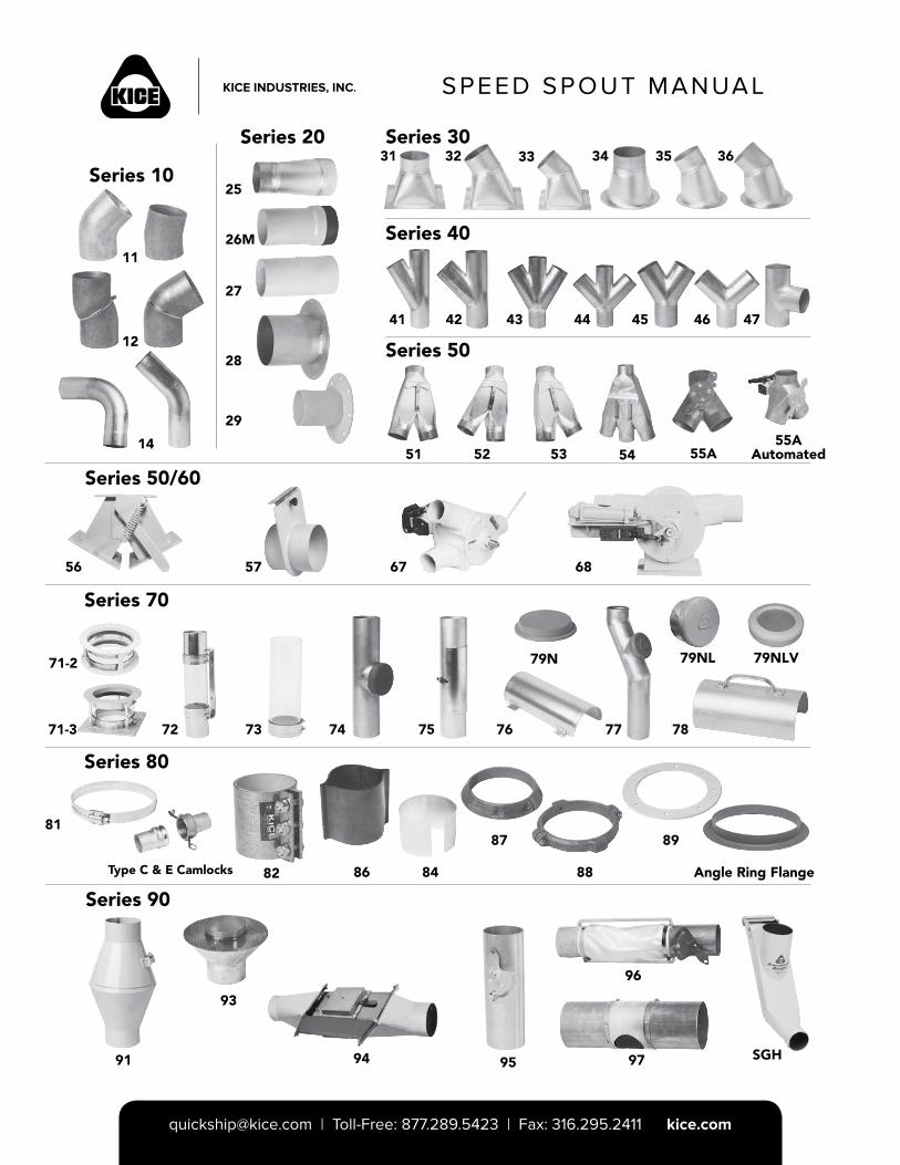
Series 10
Series 20 Series 30
Series 40
Series 50
Series 50/60
Series 70
Series 80
Series 90
11
12
14
25
26M
27
28
29
31 32 33 34 35 36
41 42 43 44 45 46 47
51 52 53 54 55A55A
Automated
56 57 67 68
81
71-3 72 73 74 75 76
79N
77 78
79NL
Type C & E Camlocks 82 84
87
88
89
Angle Ring Flange
91
93
94 95
96
97 SGH
71-2 79NLV
SPEED SPOUT MANUAL
[email protected] | Toll-Free: 877.289.5423 | Fax: 316.295.2411 kice.com
Table of Contents
SPEED SPOUT MANUAL
ELBOWS
Kice Formed Long Sweep Tube Elbows 4
Extended Tangent Flat Back Elbows 5
11 & 12 Elbows 6
Standard Long Radius Elbows 7
14 Short Radius Elbows 8
Special Long Sweep Tube Elbows & Stand-T Ells
9
Ceram-Back Elbow 9
ADAPTERS
25/26M/26F Adapters 10
27/28/29 Adapters 11
TRANSITIONS
31/32/33 Transitions 12
34/35/36 Transitions 13
BRANCH FITTINGS
41/42/43/44 Branch Fittings 14
45/46/47 Branch Fittings 15
GRAVITY VALVES
51/52/53 Gravity Diverter Valves 16
54 Dual Gravity Diverter Valves 17
55A Spout Diverter Valves 18
56 Bucket Valve 19
SLIDE GATE VALVES
57GM Slide Gate Valves 20
58GM Slide Gate Valves 21
58GA Slide Gate Valves 22
Automated Controls Package Specifications 23
DIVERTER & BIN FILL VALVES
67Q, 2-way Diverter Valves 24
67Q, 3-way Diverter Valves 25
68Q Bin Fill Valves 26
SIGHT GLASSES
71/72/73 Sight Glasses 27
LIDS, CAPS, PLUGS & SPOUTS
74/75/76/77 Fittings 28
78/79N/79NL Fittings 29
COUPLINGS AND CLAMPS
81S/84A/86N Couplings & Clamps 30
82M Heavy Duty Tube OD Compression Couplings
31
Kice 82M Heavy Duty Pipe Compression Couplings
32
FLANGES & SUPPORT RINGS
87A/88A/89 Flanges & Support Rings 33
Kice Angle Ring Flanges 34
91/93 Miscellaneous Fittings 35
MAGNET SECTIONS
94 Manual Gravity Flow Magnet Section 36
MISCELLANEOUS COMPONENTS
95 Damper & 96 Tattle Tale Fittings 37
97/Null Point Fittings/97/99 38
SGH Streamguard Blender Fitting 39
Porthole Sight Glass Assemblies 40
HOSE & CAMLOCKS
Hose & Hose Connections Products 41
Camlock Connections 42
DATA & DIMENSIONSMaterials of Construction, Tube Data, & Useful Formulas
45
Pipe and Flange Dimensions 46
Kice Round & Square Flange Dimensions
47
SPEED SPOUT MANUAL
[email protected] | Toll-Free: 877.289.5423 | Fax: 316.295.2411 kice.com4
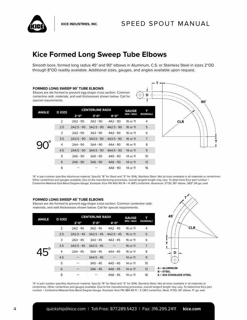
FORMED LONG SWEEP 90˚ TUBE ELBOWSElbows are die formed to prevent egg-shape cross section. Common centerline radii, materials, and wall thicknesses shown below. Call for special requirements.
FORMED LONG SWEEP 45˚ TUBE ELBOWSElbows are die formed to prevent egg-shape cross section. Common centerline radii, materials, and wall thicknesses shown below. Call for special requirements.
A = ALUMINUMB = STEELS = 304 STAINLESS STEEL
Kice Formed Long Sweep Tube ElbowsSmooth bore, formed long radius 45° and 90° elbows in Aluminum, C.S. or Stainless Steel in sizes 2"OD through 8"OD readily available. Additional sizes, gauges, and angles available upon request.
“A” in part number specifies Aluminum material. Specify “B” for Steel and “S” for 304L Stainless Steel. Not all sizes available in all materials or centerlines. Other centerlines and gauges available. Due to the manufacturing processes, overall tangent length may vary. To determine Kice part number = Centerline-Material-Size-Bend Degree-Gauge. Example: Kice PN 4A5-90-14 = 4' (48") centerline, Aluminum, 5"OD, 90° elbow, .083" (14 ga.) wall
“A” in part number specifies Aluminum material. Specify “B” for Steel and “S” for 304L Stainless Steel. Not all sizes available in all materials or centerlines. Other centerlines and gauges available. Due to the manufacturing processes, overall tangent length may vary. To determine Kice part number = Centerline-Material-Size-Bend Degree-Gauge. Example: Kice PN 3B4-45-11 = 3' (36") centerline, Steel, 4"OD, 45° elbow, 11" ga. wall.
T
T
D
90˚
CLR
ANGLE D (OD)CENTERLINE RADII GAUGE
MIN / MAXT
(NOMINAL)2'-0" 3'-0" 4'-0"
90˚
2 2A2 - 90 3A2 - 90 4A2 - 90 16 or 11 4
2.5 2A2.5 - 90 3A2.5 - 90 4A2.5 - 90 16 or 11 5
3 2A3 - 90 3A3 - 90 4A3 - 90 16 or 11 6
3.5 2A3.5 - 90 3A3.5 - 90 4A3.5 - 90 16 or 11 7
4 2A4 - 90 3A4 - 90 4A4 - 90 16 or 11 8
4.5 2A4.5 - 90 3A4.5 - 90 4A4.5 - 90 14 or 11 9
5 2A5 - 90 3A5 - 90 4A5 - 90 14 or 11 10
6 2A6 - 90 3A6 - 90 4A6 - 90 14 or 11 12
8 — — 4A8 - 90 14 or 11 16
ANGLE D (OD)CENTERLINE RADII GAUGE
MIN / MAXT
(NOMINAL)2'-0" 3'-0" 4'-0"
45˚
2 2A2 - 45 3A2 - 45 4A2 - 45 16 or 11 4
2.5 2A2.5 - 45 3A2.5 - 45 4A2.5 - 45 16 or 11 5
3 2A3 - 45 3A3 - 45 4A3 - 45 16 or 11 6
3.5 2A3.5 - 45 3A3.5 - 45 — 16 or 11 7
4 2A4 - 45 3A4 - 45 4A4 - 45 16 or 11 8
4.5 — 3A4.5 - 45 — 14 or 11 9
5 — 3A5 - 45 4A5 - 45 14 or 11 10
6 — 3A6 - 45 4A6 - 45 14 or 11 12
8 — — 4A8 - 45 14 or 11 16
45˚
T
T
D
CLR
SPEED SPOUT MANUAL
[email protected] | Toll-Free: 877.289.5423 | Fax: 316.295.2411 kice.com 5
SPEED SPOUT MANUAL
EXTENDED TANGENT “T” SERIES FLAT BACK 45° AND 90° ELBOWS
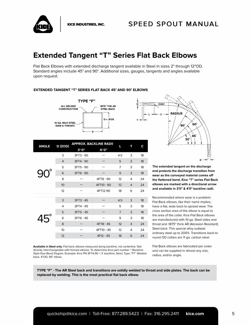
Extended Tangent “T” Series Flat Back ElbowsFlat Back Elbows with extended discharge tangent available in Steel in sizes 2" through 12"OD.Standard angles include 45° and 90°. Additional sizes, gauges, tangents and angles available upon request.
Available in Steel only. Flat back elbows measured along backline, not centerline. Not directly interchangeable with formed elbows. To determine Kice part number = Backline-Style-Size-Bend Degree. Example: Kice PN 3FT4-90 = 3' backline, Steel, Type “FT” Welded back, 4"OD, 90° elbow.
The extended tangent on the discharge end protects the discharge transition from wear as the conveyed material comes off the flattened bend. Kice “T” series Flat Back elbows are marked with a directional arrow and available in 3'0" & 4'0" backline radii.
Recommended where wear is a problem. Flat Back elbows, like their name implies, have a flat, wide back to spread wear. The cross section area of the elbow is equal to the area of the collar. Kice Flat Back elbows are manufactured with 10 ga. Steel sides and throat and .1875" thick AR (Abrasion Resistant) Steel back. This special alloy outlasts ordinary steel up to 200%. Transitions back to round OD collars are 11 ga. carbon steel.
Flat Back elbows are fabricated per order and can be supplied in almost any size, radius, and/or angle.
TYPE “F” - The AR Steel back and transitions are solidly welded to throat and side plates. The back can bereplaced by welding. This is the most practical flat back elbow.
ANGLE D (ZOD)APPROX. BACKLINE RADII
L T C3'-0" 4'-0"
90˚
3 3FT3 - 90 — 4.5 3 18
4 3FT4 - 90 — 5 3 18
5 3FT5 - 90 — 7 3 18
6 3FT6 - 90 — 9 3 18
8 — 4FT8 - 90 12 4 24
10 — 4FT10 - 90 12 4 24
12 — 4FT12-90 18 6 24
45˚
3 3FT3 - 45 — 4.5 3 18
4 3FT4 - 45 — 5 3 18
5 3FT5 - 45 — 7 3 18
6 3FT6 - 45 — 9 3 18
8 — 4FT8 - 45 12 4 24
10 — 4FT10 - 45 12 4 24
12 — 4F12 - 45 18 6 24
ALL WELDED CONSTRUCTION
10 GA. MILD STEEL (SIDE & THROAT)
TYPE “F”.1875" THK AR STEEL BACK
D x .8125
D
D
T
D
L C
FLOW
RADIUS
90˚ 60˚
45˚30˚
SPEED SPOUT MANUAL
[email protected] | Toll-Free: 877.289.5423 | Fax: 316.295.2411 kice.com6
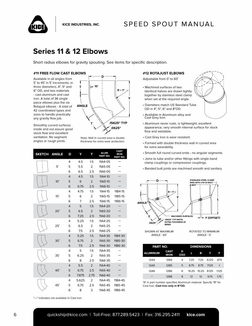
Available in all angles from 5˚ to 45˚ in 5˚ increments, in three diameters, 4", 5" and 6" OD, and two materials - cast aluminum and cast iron. A total of 36 single piece elbows plus the six Rotajust elbows - A total of 42 coordinated types and sizes to handle practically any gravity flow job.
Smoothly curved surfaces inside and out assure good stock flow and excellent sanitation. No segment angles or rough joints.
#12 ROTAJUST ELBOWS#11 FREE FLOW CAST ELBOWS
Series 11 & 12 Elbows
Adjustable from 0˚ to 60˚
Short radius elbows for gravity spouting. See items for specific description.
"—" indicates not available in Cast Iron
"A" in part number specifies Aluminum material. Specify "B" for Cast Iron. Cast Iron only in 8"OD.
D
.15625" TYP
.0625"
T
ANGLE
R = 1"10˚
T
Y
Note: Wall in curved area is double thickness for extra wear protection.
SKETCH ANGLE D Y T ALUM.PART NO.
CAST IRON
PART NO.
5˚
4 4.5 1.5 11A4-05 —
5 5.5 2 11A5-05 —
6 6.5 2.5 11A6-05 —
10˚
4 4.5 1.5 11A4-10 —
5 6 2 11A5-10 —
6 6.75 2.5 11A6-10 —
15˚
4 4.75 1.5 11A4-15 11B4-15
5 6 2 11A5-15 11B5-15
6 7 2.5 11A6-15 11B6-15
20˚
4 5 1.5 11A4-20 —
5 6.5 2 11A5-20 —
6 7.25 2.5 11A6-20 —
25˚
4 5.25 1.5 11A4-25 —
5 6.5 2 11A5-25 —
6 7.5 2.5 11A6-25 —
30˚
4 5.25 1.5 11A4-30 11B4-30
5 6.75 2 11A5-30 11B5-30
6 7.5 2.5 11A6-30 11B6-30
35˚
4 5 1.5 11A4-35 —
5 6.25 2 11A5-35 —
6 8 2.5 11A6-35 —
40˚
4 5.5 2 11A4-40 —
5 6.75 2.5 11A5-40 —
6 7.875 2.75 11A6-40 —
45˚
4 5.625 2 11A4-45 11B4-45
5 6.75 2.5 11A5-45 11B5-45
6 8 3 11A6-45 11B6-45
• Machined surfaces of two identical halves are drawn tightly together by stainless steel clamp when set at the required angle.
• Diameters match US Standard Tube OD in 4", 5", 6" and 8"OD.
• Available in Aluminum alloy and Cast Grey Iron.
• Aluminum never rusts, is lightweight, excellent appearance, very smooth internal surface for stock flow and weldable.
• Cast Grey Iron is wear resistant.
• Formed with double thickness wall in curved area for extra wearability.
• Smooth full round curved ends - no angular segments.
• Joins to tube and/or other fittings with single band clamp couplings or compression couplings.
• Banded butt joints are machined smooth and sanitary.
D
ANGLE
YL
F (OFFSET)T
.0625"
R = 1"
.15625" TYP (NOTE: EXTRA THICKNESS AT BEND)
STAINLESS STEEL CLAMP RING WITH #10-24 BOLT & NUT
MACHINED SURFACES
SHOWN AT MAXIMUM ANGLE - 60˚
ROTATED TO MINIMUM ANGLE - 0˚
PART NO. DIMENSIONS
ALUMINUMCAST IRON
D (OD)
L B Y F
12A4 12B4 4 7.25 7.25 6.125 .875
12A5 12B5 5 8.75 8.75 7.125 1
12A6 12B6 6 10.25 10.25 8.125 1.125
— 12B8 8 12 12 9.75 1.75
SPEED SPOUT MANUAL
[email protected] | Toll-Free: 877.289.5423 | Fax: 316.295.2411 kice.com 7
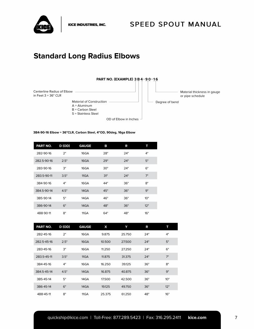
PART NO. (EXAMPLE) 3 B 4 - 9 0 - 1 6
PART NO. D (OD) GAUGE B R T
2B2-90-16 2" 16GA 28" 24" 4"
2B2.5-90-16 2.5" 16GA 29" 24" 5"
2B3-90-16 3" 16GA 30" 24" 6"
2B3.5-90-11 3.5" 11GA 31" 24" 7"
3B4-90-16 4" 16GA 44" 36" 8"
3B4.5-90-14 4.5" 14GA 45" 36" 9"
3B5-90-14 5" 14GA 46" 36" 10"
3B6-90-14 6" 14GA 48" 36" 12"
4B8-90-11 8" 11GA 64" 48" 16"
PART NO. D (OD) GAUGE X Y R T
2B2-45-16 2" 16GA 9.875 25.750 24" 4"
2B2.5-45-16 2.5" 16GA 10.500 27.500 24" 5"
2B3-45-16 3" 16GA 11.250 27.250 24" 6"
2B3.5-45-11 3.5" 11GA 11.875 31.375 24" 7"
3B4-45-16 4" 16GA 16.250 39.125 36" 8"
3B4.5-45-14 4.5" 14GA 16.875 40.875 36" 9"
3B5-45-14 5" 14GA 17.500 42.500 36" 10"
3B6-45-14 6" 14GA 19.125 49.750 36" 12"
4B8-45-11 8" 11GA 25.375 61.250 48" 16"
SPEED SPOUT MANUAL
Standard Long Radius Elbows
Centerline Radius of Elbow in Feet 3 = 36" CLR
3B4-90-16 Elbow = 36"CLR, Carbon Steel, 4"OD, 90deg, 16ga Elbow
Material thickness in gauge or pipe schedule
Material of ConstructionA = AluminumB = Carbon SteelS = Stainless Steel
Degree of bend
OD of Elbow in Inches
SPEED SPOUT MANUAL
[email protected] | Toll-Free: 877.289.5423 | Fax: 316.295.2411 kice.com8
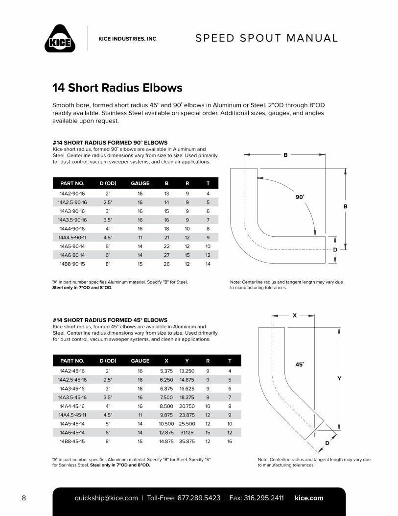
#14 SHORT RADIUS FORMED 90° ELBOWSKice short radius, formed 90˚ elbows are available in Aluminum and Steel. Centerline radius dimensions vary from size to size. Used primarily for dust control, vacuum sweeper systems, and clean air applications.
14 Short Radius ElbowsSmooth bore, formed short radius 45° and 90˚ elbows in Aluminum or Steel. 2"OD through 8"OD readily available. Stainless Steel available on special order. Additional sizes, gauges, and angles available upon request.
"A" in part number specifies Aluminum material. Specify "B" for Steel. Steel only in 7"OD and 8"OD.
Note: Centerline radius and tangent length may vary due to manufacturing tolerances.
B
B
D
90˚
PART NO. D (OD) GAUGE B R T
14A2-90-16 2" 16 13 9 4
14A2.5-90-16 2.5" 16 14 9 5
14A3-90-16 3" 16 15 9 6
14A3.5-90-16 3.5" 16 16 9 7
14A4-90-16 4" 16 18 10 8
14A4.5-90-11 4.5" 11 21 12 9
14A5-90-14 5" 14 22 12 10
14A6-90-14 6" 14 27 15 12
14B8-90-15 8" 15 26 12 14
#14 SHORT RADIUS FORMED 45° ELBOWSKice short radius, formed 45° elbows are available in Aluminum and Steel. Centerline radius dimensions vary from size to size. Used primarily for dust control, vacuum sweeper systems, and clean air applications.
"A" in part number specifies Aluminum material. Specify "B" for Steel. Specify "S" for Stainless Steel. Steel only in 7"OD and 8"OD.
PART NO. D (OD) GAUGE X Y R T
14A2-45-16 2" 16 5.375 13.250 9 4
14A2.5-45-16 2.5" 16 6.250 14.875 9 5
14A3-45-16 3" 16 6.875 16.625 9 6
14A3.5-45-16 3.5" 16 7.500 18.375 9 7
14A4-45-16 4" 16 8.500 20.750 10 8
14A4.5-45-11 4.5" 11 9.875 23.875 12 9
14A5-45-14 5" 14 10.500 25.500 12 10
14A6-45-14 6" 14 12.875 31.125 15 12
14B8-45-15 8" 15 14.875 35.875 12 16
Note: Centerline radius and tangent length may vary due to manufacturing tolerances.
45˚
X
Y
D
SPEED SPOUT MANUAL
[email protected] | Toll-Free: 877.289.5423 | Fax: 316.295.2411 kice.com 9
SPEED SPOUT MANUAL
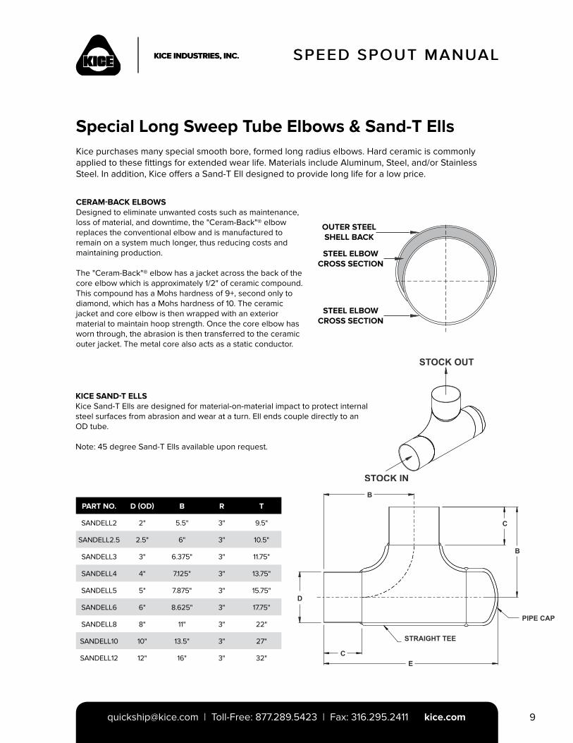
Special Long Sweep Tube Elbows & Sand-T EllsKice purchases many special smooth bore, formed long radius elbows. Hard ceramic is commonly applied to these fittings for extended wear life. Materials include Aluminum, Steel, and/or Stainless Steel. In addition, Kice offers a Sand-T Ell designed to provide long life for a low price.
CERAM-BACK ELBOWSDesigned to eliminate unwanted costs such as maintenance, loss of material, and downtime, the "Ceram-Back"® elbow replaces the conventional elbow and is manufactured to remain on a system much longer, thus reducing costs and maintaining production.
The "Ceram-Back"® elbow has a jacket across the back of the core elbow which is approximately 1/2" of ceramic compound. This compound has a Mohs hardness of 9+, second only to diamond, which has a Mohs hardness of 10. The ceramic jacket and core elbow is then wrapped with an exterior material to maintain hoop strength. Once the core elbow has worn through, the abrasion is then transferred to the ceramic outer jacket. The metal core also acts as a static conductor.
PART NO. D (OD) B R T
SANDELL2 2" 5.5" 3" 9.5"
SANDELL2.5 2.5" 6" 3" 10.5"
SANDELL3 3" 6.375" 3" 11.75"
SANDELL4 4" 7.125" 3" 13.75"
SANDELL5 5" 7.875" 3" 15.75"
SANDELL6 6" 8.625" 3" 17.75"
SANDELL8 8" 11" 3" 22"
SANDELL10 10" 13.5" 3" 27"
SANDELL12 12" 16" 3" 32"
KICE SAND-T ELLS Kice Sand-T Ells are designed for material-on-material impact to protect internal steel surfaces from abrasion and wear at a turn. Ell ends couple directly to an OD tube.
Note: 45 degree Sand-T Ells available upon request.
OUTER STEELSHELL BACK
STEEL ELBOWCROSS SECTION
STEEL ELBOWCROSS SECTION
SPEED SPOUT MANUAL
[email protected] | Toll-Free: 877.289.5423 | Fax: 316.295.2411 kice.com10
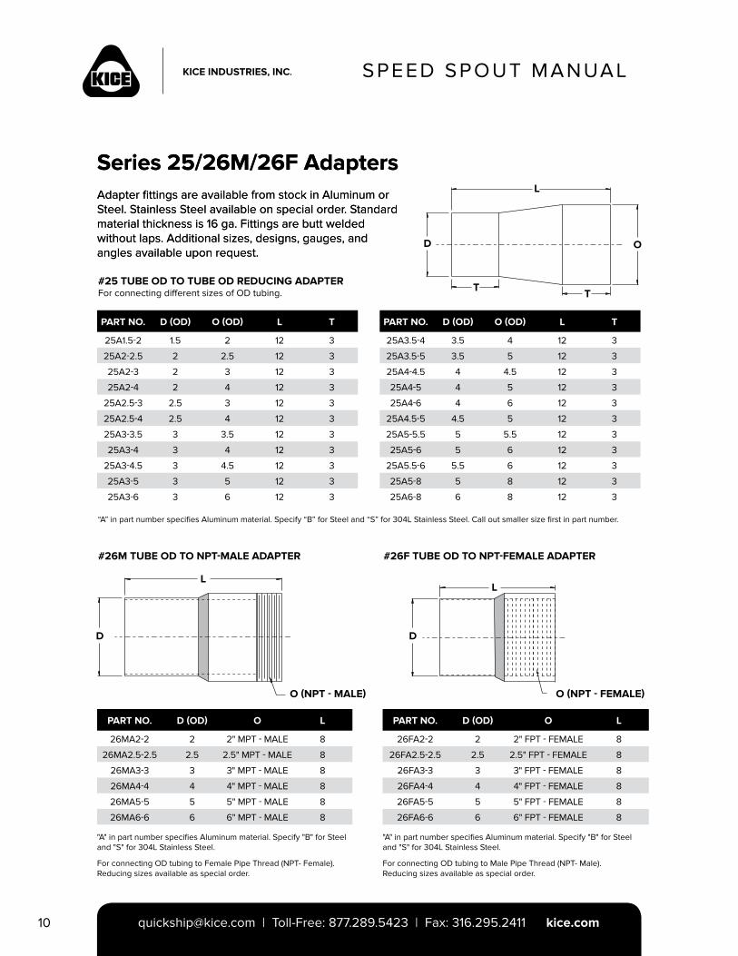
#25 TUBE OD TO TUBE OD REDUCING ADAPTERFor connecting different sizes of OD tubing.
#26M TUBE OD TO NPT-MALE ADAPTER #26F TUBE OD TO NPT-FEMALE ADAPTER
[email protected] | Toll-Free: 877.289.5423 | Fax: 316.295.2411 kice.com
Series 25/26M/26F AdaptersAdapter fittings are available from stock in Aluminum or Steel. Stainless Steel available on special order. Standard material thickness is 16 ga. Fittings are butt welded without laps. Additional sizes, designs, gauges, and angles available upon request.
L
D
T T
O
PART NO. D (OD) O (OD) L T
25A1.5-2 1.5 2 12 3
25A2-2.5 2 2.5 12 3
25A2-3 2 3 12 3
25A2-4 2 4 12 3
25A2.5-3 2.5 3 12 3
25A2.5-4 2.5 4 12 3
25A3-3.5 3 3.5 12 3
25A3-4 3 4 12 3
25A3-4.5 3 4.5 12 3
25A3-5 3 5 12 3
25A3-6 3 6 12 3
PART NO. D (OD) O L
26MA2-2 2 2" MPT - MALE 8
26MA2.5-2.5 2.5 2.5" MPT - MALE 8
26MA3-3 3 3" MPT - MALE 8
26MA4-4 4 4" MPT - MALE 8
26MA5-5 5 5" MPT - MALE 8
26MA6-6 6 6" MPT - MALE 8
PART NO. D (OD) O L
26FA2-2 2 2" FPT - FEMALE 8
26FA2.5-2.5 2.5 2.5" FPT - FEMALE 8
26FA3-3 3 3" FPT - FEMALE 8
26FA4-4 4 4" FPT - FEMALE 8
26FA5-5 5 5" FPT - FEMALE 8
26FA6-6 6 6" FPT - FEMALE 8
PART NO. D (OD) O (OD) L T
25A3.5-4 3.5 4 12 3
25A3.5-5 3.5 5 12 3
25A4-4.5 4 4.5 12 3
25A4-5 4 5 12 3
25A4-6 4 6 12 3
25A4.5-5 4.5 5 12 3
25A5-5.5 5 5.5 12 3
25A5-6 5 6 12 3
25A5.5-6 5.5 6 12 3
25A5-8 5 8 12 3
25A6-8 6 8 12 3
“A” in part number specifies Aluminum material. Specify “B” for Steel and “S” for 304L Stainless Steel. Call out smaller size first in part number.
LL
D D
O (NPT - MALE) O (NPT - FEMALE)
"A" in part number specifies Aluminum material. Specify "B" for Steel and "S" for 304L Stainless Steel.
For connecting OD tubing to Female Pipe Thread (NPT- Female).Reducing sizes available as special order.
For connecting OD tubing to Male Pipe Thread (NPT- Male).Reducing sizes available as special order.
"A" in part number specifies Aluminum material. Specify "B" for Steel and "S" for 304L Stainless Steel.
Series 25/26M/26F AdaptersAdapter fittings are available from stock in Aluminum or Steel. Stainless Steel available on special order. Standard material thickness is 16 ga. Fittings are butt welded without laps. Additional sizes, designs, gauges, and angles available upon request.
SPEED SPOUT MANUAL
[email protected] | Toll-Free: 877.289.5423 | Fax: 316.295.2411 kice.com 11
SPEED SPOUT MANUAL
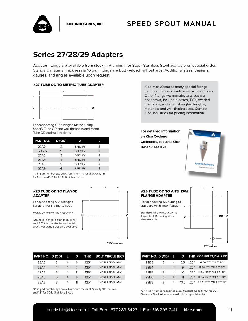
For connecting OD tubing to Metric tubing. Specify Tube OD and wall thickness and Metric Tube OD and wall thickness
For connecting OD tubing to flange or for mating to floor.
Bolt holes drilled when specified.
.125" thick flange is standard, .1875" and .25" thick available on special order. Reducing sizes also available.
For connecting OD tubing to standard ANSI 150# flange.
Standard tube construction is11 ga. steel. Reducing sizesalso available.
[email protected] | Toll-Free: 877.289.5423 | Fax: 316.295.2411 | [email protected] | Toll-Free: 877.289.5423 | Fax: 316.295.2411 kice.com
D
L
A
Series 27/28/29 AdaptersAdapter fittings are available from stock in Aluminum or Steel. Stainless Steel available on special order. Standard material thickness is 16 ga. Fittings are butt welded without laps. Additional sizes, designs, gauges, and angles available upon request.
#27 TUBE OD TO METRIC TUBE ADAPTER
#28 TUBE OD TO FLANGE ADAPTER
#29 TUBE OD TO ANSI 150# FLANGE ADAPTER
For detailed information on Kice Cyclone Collectors, request Kice Data Sheet IF-2.
“A” in part number specifies Aluminum material. Specify “B” for Steel and “S” for 304L Stainless Steel.
“A” in part number specifies Aluminum material. Specify “B” for Steel and “S” for 304L Stainless Steel.
“B” in part number specifies Steel Material. Specify “S” for 304 Stainless Steel. Aluminum available on special order.
PART NO. D (OD) A L
27A2- 2 SPECIFY 827A2.5- 2.5 SPECIFY 827A3- 3 SPECIFY 827A4- 4 SPECIFY 827A5- 5 SPECIFY 827A6- 6 SPECIFY 8
PART NO. D (OD) L O THK BOLT CIRCLE (BC)
28A3 3 4 6 .125" UNDRILLED/BLANK
28A4 4 4 7 .125" UNDRILLED/BLANK
28A5 5 4 8 .125" UNDRILLED/BLANK
28A6 6 4 9 .125" UNDRILLED/BLANK
28A8 8 4 11 .125" UNDRILLED/BLANK
PART NO. D (OD) L O THK # OF HOLES, DIA. & BC
29B3 3 4 7.5 .25" 4 EA .75" ON 6" BC
29B4 4 4 9 .25" 8 EA .75" ON 7.5" BC
29B5 5 4 10 .25" 8 EA .875" ON 8.5" BC
29B6 6 4 11 .25" 8 EA .875" ON 9.5" BC
29B8 8 4 13.5 .25" 8 EA .875" ON 11.75" BC
Kice manufactures many special fittings for customers and welcomes your inquiries. Other fittings we manufacture, but are not shown, include crosses, TY’s, welded manifolds, and special angles, lengths, materials and wall thicknesses. Contact Kice Industries for pricing information.
D
L
O
.125"
D
L
OBC
.25"
SPEED SPOUT MANUAL
[email protected] | Toll-Free: 877.289.5423 | Fax: 316.295.2411 kice.com12
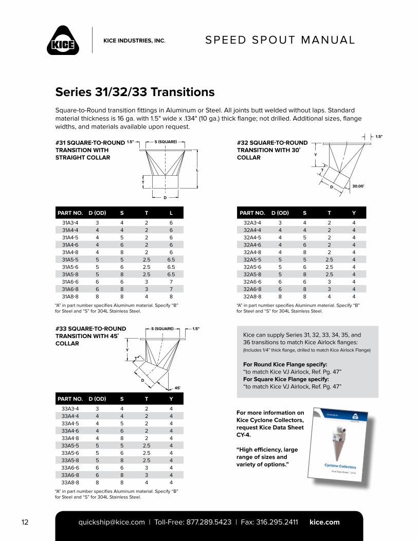
Series 31/32/33 TransitionsSquare-to-Round transition fittings in Aluminum or Steel. All joints butt welded without laps. Standard material thickness is 16 ga. with 1.5" wide x .134" (10 ga.) thick flange; not drilled. Additional sizes, flange widths, and materials available upon request.
#31 SQUARE-TO-ROUND TRANSITION WITH STRAIGHT COLLAR
For more information on Kice Cyclone Collectors, request Kice Data Sheet CY-4.
“High efficiency, large range of sizes and variety of options.”
#33 SQUARE-TO-ROUND TRANSITION WITH 45˚ COLLAR
#32 SQUARE-TO-ROUND TRANSITION WITH 30˚ COLLAR
S (SQUARE)1.5"
T
L
D
“A” in part number specifies Aluminum material. Specify “B” for Steel and “S” for 304L Stainless Steel.
“A” in part number specifies Aluminum material. Specify “B” for Steel and “S” for 304L Stainless Steel.
“A” in part number specifies Aluminum material. Specify “B” for Steel and “S” for 304L Stainless Steel.
PART NO. D (OD) S T L
31A3-4 3 4 2 631A4-4 4 4 2 631A4-5 4 5 2 631A4-6 4 6 2 631A4-8 4 8 2 631A5-5 5 5 2.5 6.531A5-6 5 6 2.5 6.531A5-8 5 8 2.5 6.531A6-6 6 6 3 731A6-8 6 8 3 731A8-8 8 8 4 8
PART NO. D (OD) S T Y
33A3-4 3 4 2 433A4-4 4 4 2 433A4-5 4 5 2 433A4-6 4 6 2 433A4-8 4 8 2 433A5-5 5 5 2.5 433A5-6 5 6 2.5 433A5-8 5 8 2.5 433A6-6 6 6 3 433A6-8 6 8 3 433A8-8 8 8 4 4
PART NO. D (OD) S T Y
32A3-4 3 4 2 432A4-4 4 4 2 432A4-5 4 5 2 432A4-6 4 6 2 432A4-8 4 8 2 432A5-5 5 5 2.5 432A5-6 5 6 2.5 432A5-8 5 8 2.5 432A6-6 6 6 3 432A6-8 6 8 3 432A8-8 8 8 4 4
S (SQUARE) 1.5"
45˚
Y
T
D
Kice can supply Series 31, 32, 33, 34, 35, and36 transitions to match Kice Airlock flanges:(Includes 1/4” thick flange, drilled to match Kice Airlock Flange)
For Round Kice Flange specify:“to match Kice VJ Airlock, Ref. Pg. 47”For Square Kice Flange specify:“to match Kice VJ Airlock, Ref. Pg. 47”
1.5"
Y
T
D 30.00˚
SPEED SPOUT MANUAL
[email protected] | Toll-Free: 877.289.5423 | Fax: 316.295.2411 kice.com 13
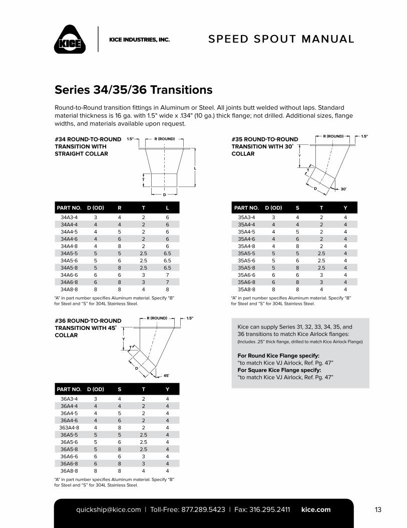
#36 ROUND-TO-ROUND TRANSITION WITH 45˚ COLLAR
SPEED SPOUT MANUAL
Series 34/35/36 TransitionsRound-to-Round transition fittings in Aluminum or Steel. All joints butt welded without laps. Standard material thickness is 16 ga. with 1.5" wide x .134" (10 ga.) thick flange; not drilled. Additional sizes, flange widths, and materials available upon request.
#34 ROUND-TO-ROUND TRANSITION WITH STRAIGHT COLLAR
#35 ROUND-TO-ROUND TRANSITION WITH 30˚ COLLAR
“A” in part number specifies Aluminum material. Specify “B” for Steel and “S” for 304L Stainless Steel.
“A” in part number specifies Aluminum material. Specify “B” for Steel and “S” for 304L Stainless Steel.
“A” in part number specifies Aluminum material. Specify “B” for Steel and “S” for 304L Stainless Steel.
PART NO. D (OD) R T L
34A3-4 3 4 2 634A4-4 4 4 2 634A4-5 4 5 2 634A4-6 4 6 2 634A4-8 4 8 2 634A5-5 5 5 2.5 6.534A5-6 5 6 2.5 6.534A5-8 5 8 2.5 6.534A6-6 6 6 3 734A6-8 6 8 3 734A8-8 8 8 4 8
PART NO. D (OD) S T Y
36A3-4 3 4 2 436A4-4 4 4 2 436A4-5 4 5 2 436A4-6 4 6 2 4
363A4-8 4 8 2 436A5-5 5 5 2.5 436A5-6 5 6 2.5 436A5-8 5 8 2.5 436A6-6 6 6 3 436A6-8 6 8 3 436A8-8 8 8 4 4
PART NO. D (OD) S T Y
35A3-4 3 4 2 435A4-4 4 4 2 435A4-5 4 5 2 435A4-6 4 6 2 435A4-8 4 8 2 435A5-5 5 5 2.5 435A5-6 5 6 2.5 435A5-8 5 8 2.5 435A6-6 6 6 3 435A6-8 6 8 3 435A8-8 8 8 4 4
Kice can supply Series 31, 32, 33, 34, 35, and36 transitions to match Kice Airlock flanges:(Includes .25” thick flange, drilled to match Kice Airlock Flange)
For Round Kice Flange specify:“to match Kice VJ Airlock, Ref. Pg. 47”For Square Kice Flange specify:“to match Kice VJ Airlock, Ref. Pg. 47”
T
1.5" R (ROUND)
D
L
R (ROUND) 1.5"
T
D 30˚
R (ROUND) 1.5"
Y
T
D
45˚
SPEED SPOUT MANUAL
[email protected] | Toll-Free: 877.289.5423 | Fax: 316.295.2411 kice.com14
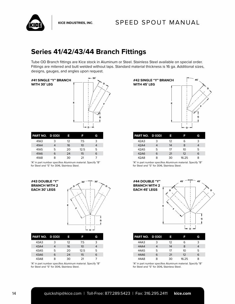
Series 41/42/43/44 Branch FittingsTube OD Branch fittings are Kice stock in Aluminum or Steel. Stainless Steel available on special order. Fittings are mitered and butt welded without laps. Standard material thickness is 16 ga. Additional sizes, designs, gauges, and angles upon request.
#41 SINGLE “Y” BRANCH WITH 30˚ LEG
#43 DOUBLE “Y” BRANCH WITH 2 EACH 30˚ LEGS
#44 DOUBLE “Y” BRANCH WITH 2 EACH 45˚ LEGS
#42 SINGLE “Y” BRANCH WITH 45˚ LEG
“A” in part number specifies Aluminum material. Specify “B” for Steel and “S” for 304L Stainless Steel.
“A” in part number specifies Aluminum material. Specify “B” for Steel and “S” for 304L Stainless Steel.
“A” in part number specifies Aluminum material. Specify “B” for Steel and “S” for 304L Stainless Steel.
“A” in part number specifies Aluminum material. Specify “B” for Steel and “S” for 304L Stainless Steel.
PART NO. D (OD) E F G
41A3 3 12 7.5 341A4 4 16 10 441A5 5 20 12.5 541A6 6 24 15 641A8 8 30 21 7
PART NO. D (OD) E F G
43A3 3 12 7.5 343A4 4 16 10 443A5 5 20 12.5 543A6 6 24 15 643A8 8 30 21 7
PART NO. D (OD) E F G
42A3 3 12 6 342A4 4 14 8 442A5 5 17 10 542A6 6 21 12 642A8 8 30 16.25 8
PART NO. D (OD) E F G
44A3 3 12 6 344A4 4 14 8 444A5 5 17 10 544A6 6 21 12 644A8 8 30 16.25 8
D
D
E F
G
30˚
D
D
EF
G
45˚
D
EF
G
D
D
30˚ 30˚
EF
G
D
DD
45˚ 45˚
SPEED SPOUT MANUAL
[email protected] | Toll-Free: 877.289.5423 | Fax: 316.295.2411 kice.com 15
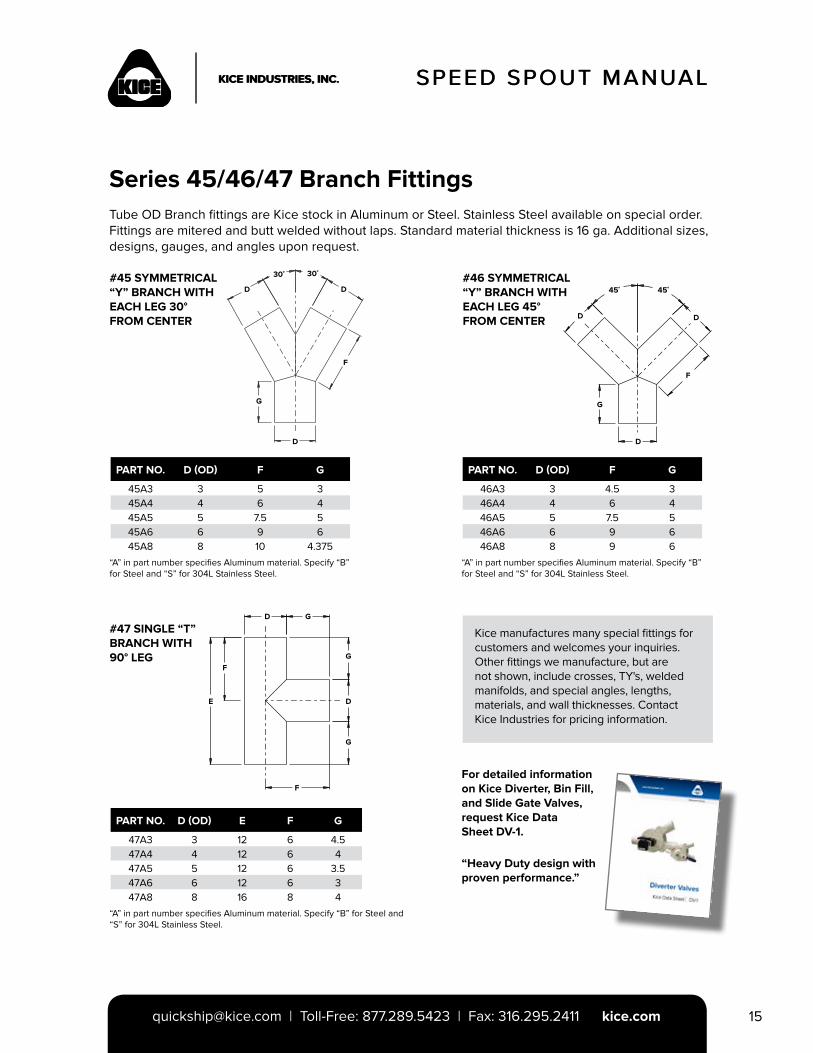
“A” in part number specifies Aluminum material. Specify “B” for Steel and “S” for 304L Stainless Steel.
“A” in part number specifies Aluminum material. Specify “B” for Steel and “S” for 304L Stainless Steel.
“A” in part number specifies Aluminum material. Specify “B” for Steel and “S” for 304L Stainless Steel.
PART NO. D (OD) F G
45A3 3 5 345A4 4 6 445A5 5 7.5 545A6 6 9 645A8 8 10 4.375
PART NO. D (OD) E F G
47A3 3 12 6 4.547A4 4 12 6 447A5 5 12 6 3.547A6 6 12 6 347A8 8 16 8 4
PART NO. D (OD) F G
46A3 3 4.5 346A4 4 6 446A5 5 7.5 546A6 6 9 646A8 8 9 6
Series 45/46/47 Branch FittingsTube OD Branch fittings are Kice stock in Aluminum or Steel. Stainless Steel available on special order. Fittings are mitered and butt welded without laps. Standard material thickness is 16 ga. Additional sizes, designs, gauges, and angles upon request.
#45 SYMMETRICAL “Y” BRANCH WITH EACH LEG 30° FROM CENTER
#47 SINGLE “T” BRANCH WITH 90° LEG
#46 SYMMETRICAL “Y” BRANCH WITH EACH LEG 45° FROM CENTER
For detailed information on Kice Diverter, Bin Fill, and Slide Gate Valves, request Kice Data Sheet DV-1.
“Heavy Duty design with proven performance.”
Kice manufactures many special fittings forcustomers and welcomes your inquiries.Other fittings we manufacture, but are not shown, include crosses, TY's, welded manifolds, and special angles, lengths, materials, and wall thicknesses. Contact Kice Industries for pricing information.
SPEED SPOUT MANUAL
D D
F
G
D
30˚ 30˚
D D
F
G
D
45˚ 45˚
D
F
F
E D
G
G
G
SPEED SPOUT MANUAL
[email protected] | Toll-Free: 877.289.5423 | Fax: 316.295.2411 kice.com16
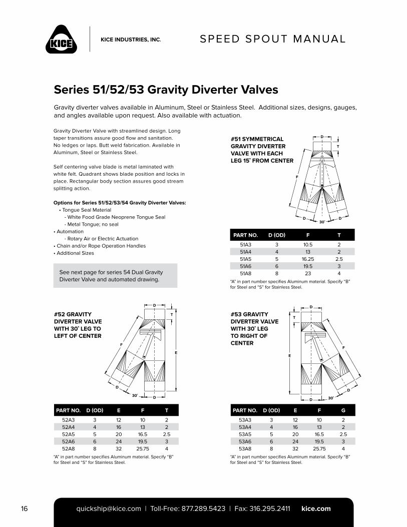
Series 51/52/53 Gravity Diverter ValvesGravity diverter valves available in Aluminum, Steel or Stainless Steel. Additional sizes, designs, gauges, and angles available upon request. Also available with actuation.
#52 GRAVITY DIVERTER VALVE WITH 30˚ LEG TO LEFT OF CENTER
#53 GRAVITY DIVERTER VALVE WITH 30˚ LEG TO RIGHT OF CENTER
#51 SYMMETRICAL GRAVITY DIVERTER VALVE WITH EACH LEG 15˚ FROM CENTER
“A” in part number specifies Aluminum material. Specify “B” for Steel and “S” for Stainless Steel.
“A” in part number specifies Aluminum material. Specify “B” for Steel and “S” for Stainless Steel.
“A” in part number specifies Aluminum material. Specify “B” for Steel and “S” for Stainless Steel.
PART NO. D (OD) E F T
52A3 3 12 10 252A4 4 16 13 252A5 5 20 16.5 2.552A6 6 24 19.5 352A8 8 32 25.75 4
PART NO. D (OD) F T
51A3 3 10.5 251A4 4 13 251A5 5 16.25 2.551A6 6 19.5 351A8 8 23 4
PART NO. D (OD) E F G
53A3 3 12 10 253A4 4 16 13 253A5 5 20 16.5 2.553A6 6 24 19.5 353A8 8 32 25.75 4
Gravity Diverter Valve with streamlined design. Long taper transitions assure good flow and sanitation. No ledges or laps. Butt weld fabrication. Available in Aluminum, Steel or Stainless Steel. Self centering valve blade is metal laminated with white felt. Quadrant shows blade position and locks in place. Rectangular body section assures good stream splitting action.
Options for Series 51/52/53/54 Gravity Diverter Valves: • Tongue Seal Material - White Food Grade Neoprene Tongue Seal - Metal Tongue; no seal• Automation - Rotary Air or Electric Actuation• Chain and/or Rope Operation Handles• Additional Sizes
See next page for series 54 Dual Gravity Diverter Valve and automated drawing.
DD
D
T
F
30˚
D
D
E
TT
D
E
F
D
D 30˚
D
F
30˚
SPEED SPOUT MANUAL
[email protected] | Toll-Free: 877.289.5423 | Fax: 316.295.2411 kice.com 17
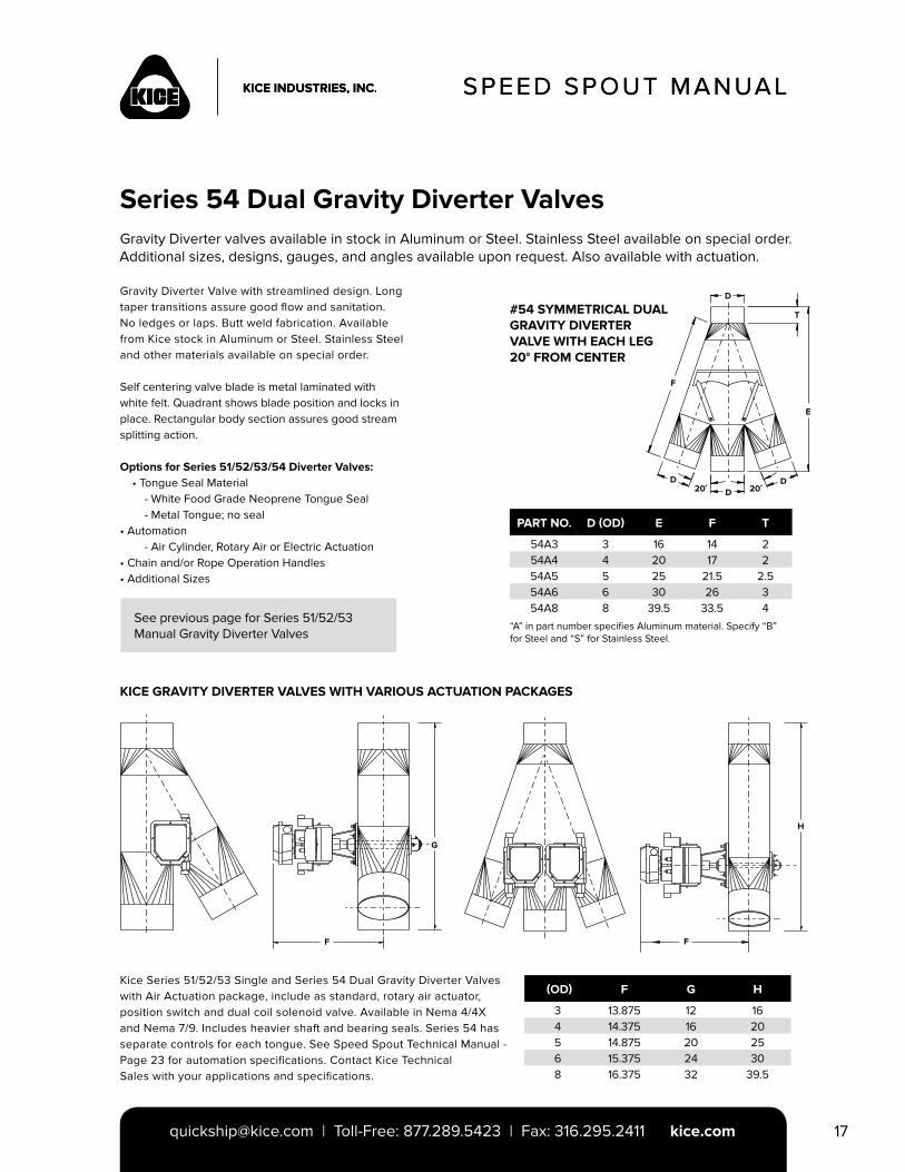
Gravity Diverter valves available in stock in Aluminum or Steel. Stainless Steel available on special order.Additional sizes, designs, gauges, and angles available upon request. Also available with actuation.
#54 SYMMETRICAL DUAL GRAVITY DIVERTER VALVE WITH EACH LEG 20° FROM CENTER
KICE GRAVITY DIVERTER VALVES WITH VARIOUS ACTUATION PACKAGES
“A” in part number specifies Aluminum material. Specify “B” for Steel and “S” for Stainless Steel.
PART NO. D (OD) E F T
54A3 3 16 14 254A4 4 20 17 254A5 5 25 21.5 2.554A6 6 30 26 354A8 8 39.5 33.5 4
(OD) F G H
3 13.875 12 164 14.375 16 205 14.875 20 256 15.375 24 308 16.375 32 39.5
Gravity Diverter Valve with streamlined design. Long taper transitions assure good flow and sanitation. No ledges or laps. Butt weld fabrication. Available from Kice stock in Aluminum or Steel. Stainless Steel and other materials available on special order.
Self centering valve blade is metal laminated with white felt. Quadrant shows blade position and locks in place. Rectangular body section assures good stream splitting action.
Options for Series 51/52/53/54 Diverter Valves: • Tongue Seal Material - White Food Grade Neoprene Tongue Seal - Metal Tongue; no seal• Automation - Air Cylinder, Rotary Air or Electric Actuation• Chain and/or Rope Operation Handles• Additional Sizes
Kice Series 51/52/53 Single and Series 54 Dual Gravity Diverter Valves with Air Actuation package, include as standard, rotary air actuator, position switch and dual coil solenoid valve. Available in Nema 4/4X and Nema 7/9. Includes heavier shaft and bearing seals. Series 54 has separate controls for each tongue. See Speed Spout Technical Manual - Page 23 for automation specifications. Contact Kice TechnicalSales with your applications and specifications.
See previous page for Series 51/52/53Manual Gravity Diverter Valves
SPEED SPOUT MANUAL
Series 54 Dual Gravity Diverter Valves
D
D DD 20˚20˚
F
E
T
H
FF
G
SPEED SPOUT MANUAL
[email protected] | Toll-Free: 877.289.5423 | Fax: 316.295.2411 kice.com18
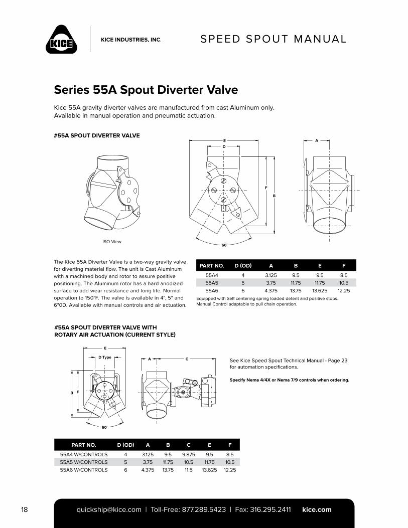
Series 55A Spout Diverter ValveKice 55A gravity diverter valves are manufactured from cast Aluminum only.Available in manual operation and pneumatic actuation.
#55A SPOUT DIVERTER VALVE
Equipped with Self centering spring loaded detent and positive stops. Manual Control adaptable to pull chain operation.
PART NO. D (OD) A B E F
55A4 4 3.125 9.5 9.5 8.555A5 5 3.75 11.75 11.75 10.555A6 6 4.375 13.75 13.625 12.25
The Kice 55A Diverter Valve is a two-way gravity valve for diverting material flow. The unit is Cast Aluminum with a machined body and rotor to assure positive positioning. The Aluminum rotor has a hard anodized surface to add wear resistance and long life. Normaloperation to 150°F. The valve is available in 4", 5" and 6"0D. Available with manual controls and air actuation.
ISO View
DE
F
B
60˚
A
#55A SPOUT DIVERTER VALVE WITH ROTARY AIR ACTUATION (CURRENT STYLE)
PART NO. D (OD) A B C E F
55A4 W/CONTROLS 4 3.125 9.5 9.875 9.5 8.555A5 W/CONTROLS 5 3.75 11.75 10.5 11.75 10.555A6 W/CONTROLS 6 4.375 13.75 11.5 13.625 12.25
See Kice Speed Spout Technical Manual - Page 23 for automation specifications.
Specify Nema 4/4X or Nema 7/9 controls when ordering.
E
D Type
B F
60˚
A C
SPEED SPOUT MANUAL
[email protected] | Toll-Free: 877.289.5423 | Fax: 316.295.2411 kice.com 19
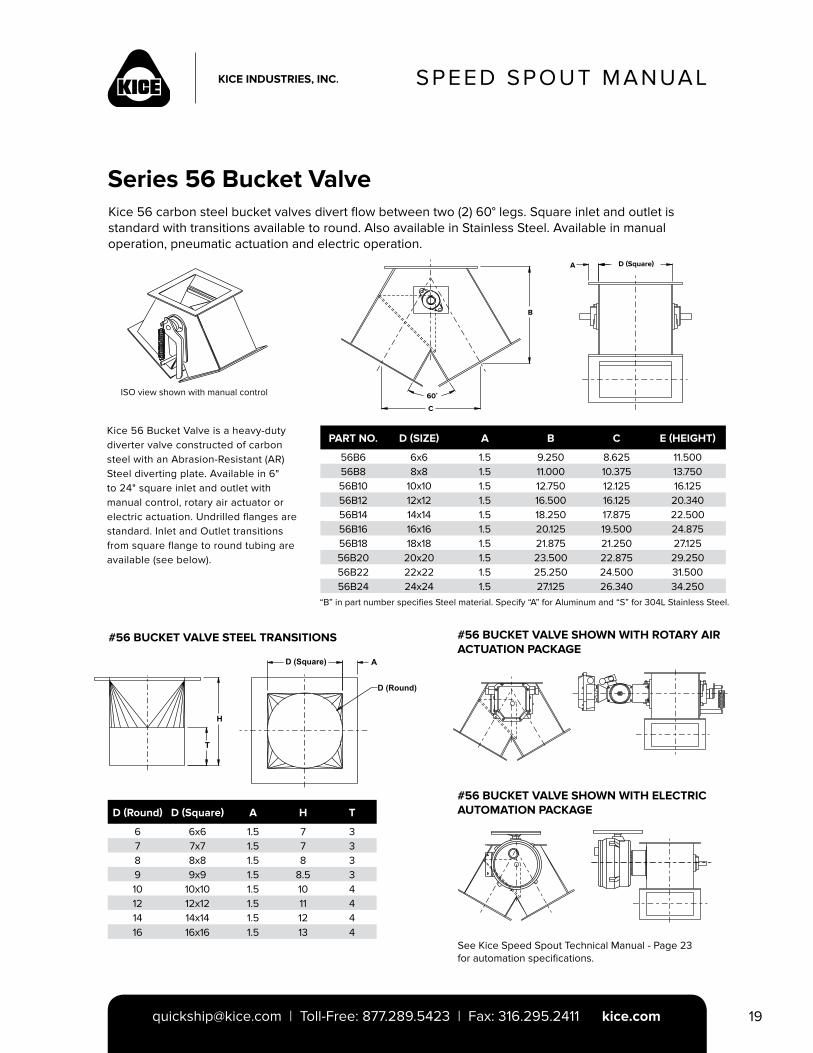
Kice 56 carbon steel bucket valves divert flow between two (2) 60° legs. Square inlet and outlet is standard with transitions available to round. Also available in Stainless Steel. Available in manual operation, pneumatic actuation and electric operation.
“B” in part number specifies Steel material. Specify “A” for Aluminum and “S” for 304L Stainless Steel.
PART NO. D (SIZE) A B C E (HEIGHT)
56B6 6x6 1.5 9.250 8.625 11.50056B8 8x8 1.5 11.000 10.375 13.75056B10 10x10 1.5 12.750 12.125 16.12556B12 12x12 1.5 16.500 16.125 20.34056B14 14x14 1.5 18.250 17.875 22.50056B16 16x16 1.5 20.125 19.500 24.87556B18 18x18 1.5 21.875 21.250 27.12556B20 20x20 1.5 23.500 22.875 29.25056B22 22x22 1.5 25.250 24.500 31.50056B24 24x24 1.5 27.125 26.340 34.250
D (Round) D (Square) A H T
6 6x6 1.5 7 37 7x7 1.5 7 38 8x8 1.5 8 39 9x9 1.5 8.5 310 10x10 1.5 10 412 12x12 1.5 11 414 14x14 1.5 12 416 16x16 1.5 13 4
Kice 56 Bucket Valve is a heavy-duty diverter valve constructed of carbon steel with an Abrasion-Resistant (AR) Steel diverting plate. Available in 6" to 24" square inlet and outlet with manual control, rotary air actuator or electric actuation. Undrilled flanges are standard. Inlet and Outlet transitions from square flange to round tubing are available (see below).
Series 56 Bucket Valve
B
C
60˚
A D (Square)
ISO view shown with manual control
#56 BUCKET VALVE STEEL TRANSITIONS #56 BUCKET VALVE SHOWN WITH ROTARY AIR ACTUATION PACKAGE
#56 BUCKET VALVE SHOWN WITH ELECTRIC AUTOMATION PACKAGE
See Kice Speed Spout Technical Manual - Page 23 for automation specifications.
SPEED SPOUT MANUAL
[email protected] | Toll-Free: 877.289.5423 | Fax: 316.295.2411 kice.com20
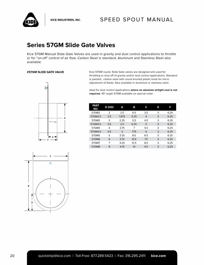
Series 57GM Slide Gate ValvesKice 57GM Manual Slide Gate Valves are used in gravity and dust control applications to throttle or for "on-off ' control of air flow. Carbon Steel is standard; Aluminum and Stainless Steel also available.
#57GM SLIDE GATE VALVE
PART NO.
D (OD) A B C E F
57GM2 2 2.5 6.5 3.5 3 6.2557GM2.5 2.5 1.875 5.25 4 3 6.2557GM3 3 2.25 5.5 4.5 3 6.25
57GM3.5 3.5 2.5 6.25 5 3 6.2557GM4 4 2.75 7 5.5 3 6.25
57GM4.5 4.5 3 7.75 6 3 6.2557GM5 5 3.25 8.5 6.5 3 6.2557GM6 6 3.75 10.5 7.5 3 6.2557GM7 7 4.25 12.5 8.5 3 6.2557GM8 8 4.75 14 9.5 3 6.25
Kice 57GM round, Slide Gate valves are designed and used for throttling or shut-off of gravity and/or dust control applications. Standard is painted, carbon steel with round knurled plastic knob for micro adjustment of blade. Also available in aluminum or stainless steel.
Ideal for dust control applications where an absolute airtight seal is not required. 45° angle 57GM available on special order.
Inlet
D
EF
B
C
A
SPEED SPOUT MANUAL
[email protected] | Toll-Free: 877.289.5423 | Fax: 316.295.2411 kice.com 21
SPEED SPOUT MANUAL
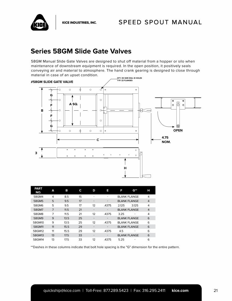
Series 58GM Slide Gate Valves58GM Manual Slide Gate Valves are designed to shut off material from a hopper or silo when maintenance of downstream equipment is required. In the open position, it positively seals conveying air and material to atmosphere. The hand crank gearing is designed to close through material in case of an upset condition.
#58GM SLIDE GATE VALVE
PART NO.
A B C D E F G** H
58GM4 4 8.5 15 - - BLANK FLANGE 458GM5 5 9.5 17 - - BLANK FLANGE 458GM6 5 9.5 17 12 .4375 2.125 3.125 458GM7 7 11.5 21 - - BLANK FLANGE 458GM8 7 11.5 21 12 .4375 3.25 - 458GM9 9 13.5 25 - - BLANK FLANGE 658GM10 9 13.5 25 12 .4375 BLANK FLANGE 658GM11 11 15.5 29 - - BLANK FLANGE 658GM12 11 15.5 29 12 .4375 4.5 - 658GM13 13 17.5 33 - - BLANK FLANGE 658GM14 13 17.5 33 12 .4375 5.25 - 6
**Dashes in these columns indicate that bolt hole spacing is the "G" dimension for the entire pattern.
B
A SQ.
C
QTY. (D) SIZE (DIA. E) HOLES TYP. (2) FLANGES
G
F
F
G
4.75NOM.
H
3
OPEN
SPEED SPOUT MANUAL
[email protected] | Toll-Free: 877.289.5423 | Fax: 316.295.2411 kice.com22
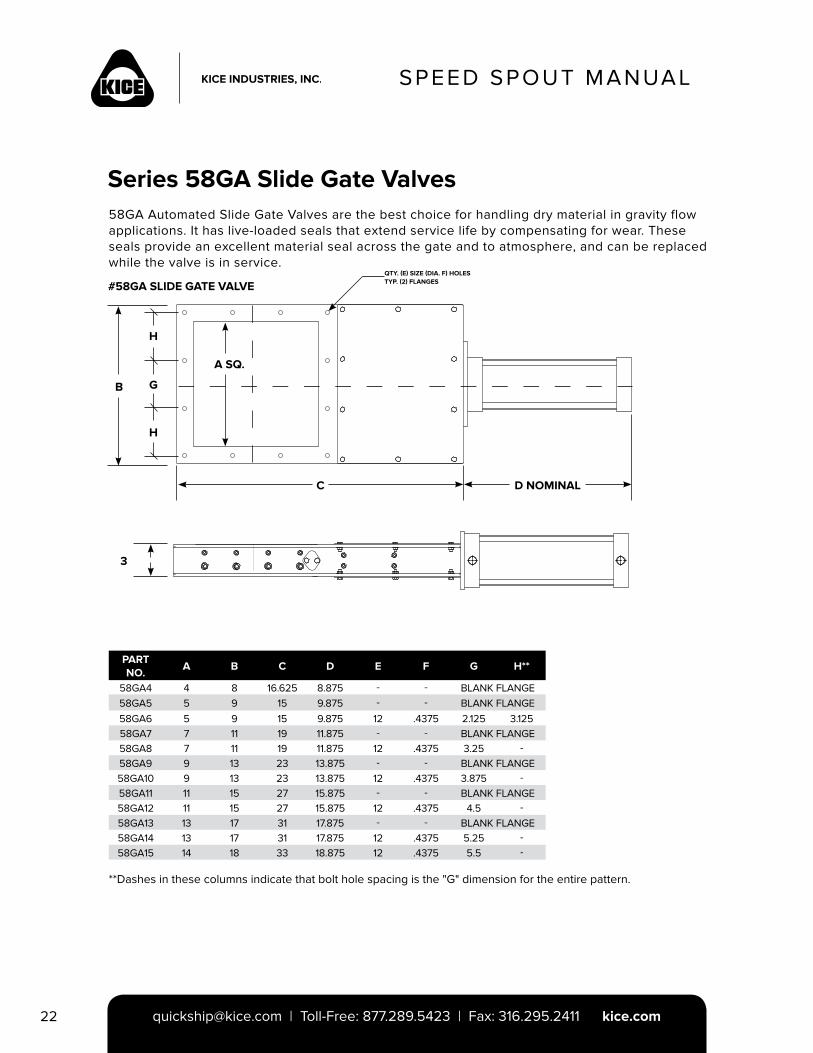
Series 58GA Slide Gate Valves58GA Automated Slide Gate Valves are the best choice for handling dry material in gravity flow applications. It has live-loaded seals that extend service life by compensating for wear. These seals provide an excellent material seal across the gate and to atmosphere, and can be replaced while the valve is in service.
#58GA SLIDE GATE VALVE
B
A SQ.
C
QTY. (E) SIZE (DIA. F) HOLES TYP. (2) FLANGES
H
H
G
3
PART NO.
A B C D E F G H**
58GA4 4 8 16.625 8.875 - - BLANK FLANGE58GA5 5 9 15 9.875 - - BLANK FLANGE58GA6 5 9 15 9.875 12 .4375 2.125 3.12558GA7 7 11 19 11.875 - - BLANK FLANGE58GA8 7 11 19 11.875 12 .4375 3.25 -58GA9 9 13 23 13.875 - - BLANK FLANGE58GA10 9 13 23 13.875 12 .4375 3.875 -58GA11 11 15 27 15.875 - - BLANK FLANGE58GA12 11 15 27 15.875 12 .4375 4.5 -58GA13 13 17 31 17.875 - - BLANK FLANGE58GA14 13 17 31 17.875 12 .4375 5.25 -58GA15 14 18 33 18.875 12 .4375 5.5 -
**Dashes in these columns indicate that bolt hole spacing is the "G" dimension for the entire pattern.
D NOMINAL
SPEED SPOUT MANUAL
[email protected] | Toll-Free: 877.289.5423 | Fax: 316.295.2411 kice.com 23
SPEED SPOUT MANUAL
Kice Automation Control Package Specifications and Options
STANDARD ROTARY ACTUATOR WITH NEMA 4/4X CONTROLS:
• Double Acting Rotary Air Actuator (based on 80-120 PSIG clean, dry, plant air supply).
• Dual Coil Nema 4/4X Solenoid Valve, NAMUR mount, with 120VAC coils and DIN connectors each end, flow control exhaust mufflers, bracketing and mounting.
• Position Switch with 2 each mechanical limit switches, Nema 4/4X, internal terminal strip, 120VAC, .5" NPT conduit connection, bracketing and mounting.
STANDARD ROTARY ACTUATOR WITH NEMA 7/9 CONTROLS:
• Double Acting Rotary Air Actuator (based on 80-120 PSIG clean, dry, plant air supply).
• Dual Coil Nema 4/4X Solenoid Valve, NAMUR mount, with 120VAC coils and DIN connectors each end, flow control exhaust mufflers, bracketing and mounting.
• Position Switch with 2 each mechanical limit switches, Nema 4/4X/7/9, internal terminal strip, 120VAC, .5'' NPT conduit connection, bracketing and mounting.
STANDARD ELECTRIC ACTUATION WITH NEMA 4/4X CONTROLS:
• 120vAC Electric Actuator, Nema 4/4X, with internal heater and thermostat, torque-limiting system, 2 each extra limit switches, manual override, .75" NPT conduit connection, bracketing and mounting.
STANDARD AIR CYLINDER ACTUATION WITH NEMA 4/4X CONTROLS:
• Double Acting Air Cylinder (based on 80-120 PSIG clean, dry, plant air supply), covered with expanded metal guard.
• Dual Coil Nema 4/4X Solenoid Valve, with 120VAC coils and DIN connectors each end, flow control exhaust mufflers, bracketing and mounting.
• Position Switch with 2 each mechanical limit switches, Nema 4/4X, internal terminal strip, 120VAC, .5" NPT conduit connection, bracketing and mounting.
STANDARD AIR CYLINDER ACTUATION WITH NEMA 7/9 CONTROLS:
• Double Acting Air Cylinder (based on 80-120 PSIG clean, dry, plant air supply), covered with expanded metal guard.
• Dual Coil Nema 4/4X/7/9 Solenoid Valve, with 120VAC coils and DIN connectors each end, flow control exhaust mufflers, bracketing and mounting.
• Position Switch with 2 each mechanical limit switches, Nema 4/4X/7/9, internal terminal strip, 120VAC, .5" NPT conduit connection, bracketing and mounting.
KICE AUTOMATION OPTIONS:
Single Coil solenoid valves, other voltages & designs, switch configurations, or other branded OEM equipment available upon request and specification.
Contact Kice Technical Sales for more information or your specifications.
SPEED SPOUT MANUAL
[email protected] | Toll-Free: 877.289.5423 | Fax: 316.295.2411 kice.com24
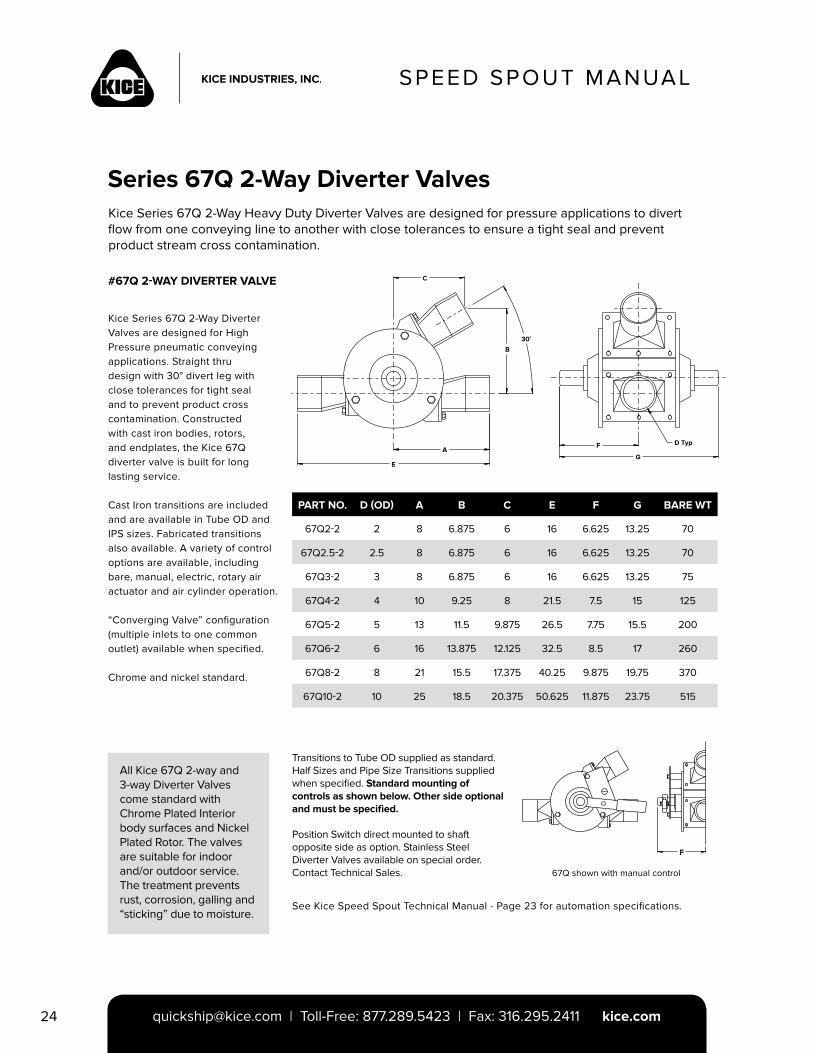
Kice Series 67Q 2-Way Heavy Duty Diverter Valves are designed for pressure applications to divert flow from one conveying line to another with close tolerances to ensure a tight seal and prevent product stream cross contamination.
Transitions to Tube OD supplied as standard. Half Sizes and Pipe Size Transitions supplied when specified. Standard mounting of controls as shown below. Other side optional and must be specified.
Position Switch direct mounted to shaft opposite side as option. Stainless Steel Diverter Valves available on special order. Contact Technical Sales.
PART NO. D (OD) A B C E F G BARE WT
67Q2-2 2 8 6.875 6 16 6.625 13.25 70
67Q2.5-2 2.5 8 6.875 6 16 6.625 13.25 70
67Q3-2 3 8 6.875 6 16 6.625 13.25 75
67Q4-2 4 10 9.25 8 21.5 7.5 15 125
67Q5-2 5 13 11.5 9.875 26.5 7.75 15.5 200
67Q6-2 6 16 13.875 12.125 32.5 8.5 17 260
67Q8-2 8 21 15.5 17.375 40.25 9.875 19.75 370
67Q10-2 10 25 18.5 20.375 50.625 11.875 23.75 515
Kice Series 67Q 2-Way Diverter Valves are designed for High Pressure pneumatic conveying applications. Straight thru design with 30° divert leg with close tolerances for tight seal and to prevent product cross contamination. Constructed with cast iron bodies, rotors, and endplates, the Kice 67Q diverter valve is built for long lasting service.
Cast Iron transitions are included and are available in Tube OD and IPS sizes. Fabricated transitions also available. A variety of control options are available, including bare, manual, electric, rotary air actuator and air cylinder operation.
“Converging Valve” configuration (multiple inlets to one common outlet) available when specified.
Chrome and nickel standard.
Series 67Q 2-Way Diverter Valves
#67Q 2-WAY DIVERTER VALVE C
30˚
B
A
E
F
G
D Typ
All Kice 67Q 2-way and 3-way Diverter Valves come standard with Chrome Plated Interior body surfaces and Nickel Plated Rotor. The valves are suitable for indoor and/or outdoor service. The treatment prevents rust, corrosion, galling and “sticking” due to moisture.
67Q shown with manual control
See Kice Speed Spout Technical Manual - Page 23 for automation specifications.
F
SPEED SPOUT MANUAL
[email protected] | Toll-Free: 877.289.5423 | Fax: 316.295.2411 kice.com 25
SPEED SPOUT MANUAL
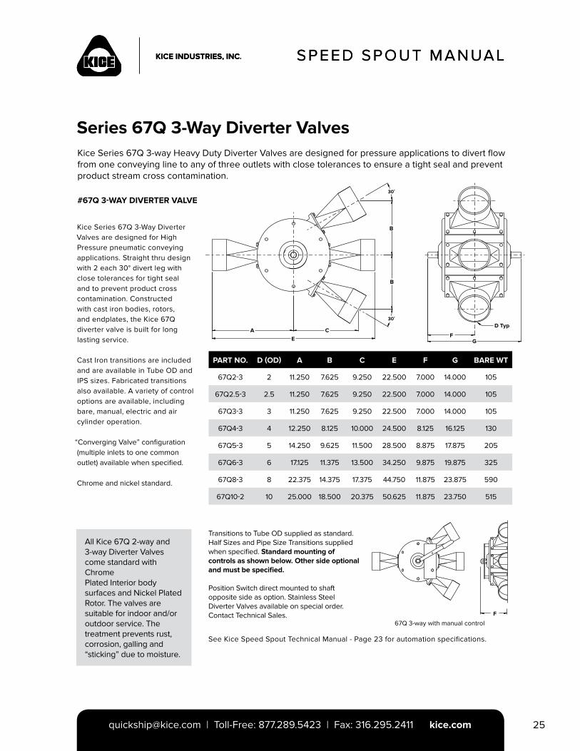
Series 67Q 3-Way Diverter ValvesKice Series 67Q 3-way Heavy Duty Diverter Valves are designed for pressure applications to divert flow from one conveying line to any of three outlets with close tolerances to ensure a tight seal and prevent product stream cross contamination.
PART NO. D (OD) A B C E F G BARE WT
67Q2-3 2 11.250 7.625 9.250 22.500 7.000 14.000 105
67Q2.5-3 2.5 11.250 7.625 9.250 22.500 7.000 14.000 105
67Q3-3 3 11.250 7.625 9.250 22.500 7.000 14.000 105
67Q4-3 4 12.250 8.125 10.000 24.500 8.125 16.125 130
67Q5-3 5 14.250 9.625 11.500 28.500 8.875 17.875 205
67Q6-3 6 17.125 11.375 13.500 34.250 9.875 19.875 325
67Q8-3 8 22.375 14.375 17.375 44.750 11.875 23.875 590
67Q10-2 10 25.000 18.500 20.375 50.625 11.875 23.750 515
Kice Series 67Q 3-Way Diverter Valves are designed for High Pressure pneumatic conveying applications. Straight thru design with 2 each 30° divert leg with close tolerances for tight seal and to prevent product cross contamination. Constructed with cast iron bodies, rotors, and endplates, the Kice 67Q diverter valve is built for long lasting service.
Cast Iron transitions are included and are available in Tube OD and IPS sizes. Fabricated transitions also available. A variety of control options are available, including bare, manual, electric and air cylinder operation.
“Converging Valve” configuration (multiple inlets to one common outlet) available when specified.
Chrome and nickel standard.
#67Q 3-WAY DIVERTER VALVE
All Kice 67Q 2-way and 3-way Diverter Valves come standard with ChromePlated Interior body surfaces and Nickel PlatedRotor. The valves are suitable for indoor and/oroutdoor service. The treatment prevents rust,corrosion, galling and “sticking” due to moisture.
Transitions to Tube OD supplied as standard. Half Sizes and Pipe Size Transitions supplied when specified. Standard mounting of controls as shown below. Other side optional and must be specified.
Position Switch direct mounted to shaft opposite side as option. Stainless Steel Diverter Valves available on special order. Contact Technical Sales.
67Q 3-way with manual control
See Kice Speed Spout Technical Manual - Page 23 for automation specifications.
30˚
B
B
30˚
CE
AF
G
D Typ
F
SPEED SPOUT MANUAL
[email protected] | Toll-Free: 877.289.5423 | Fax: 316.295.2411 kice.com26
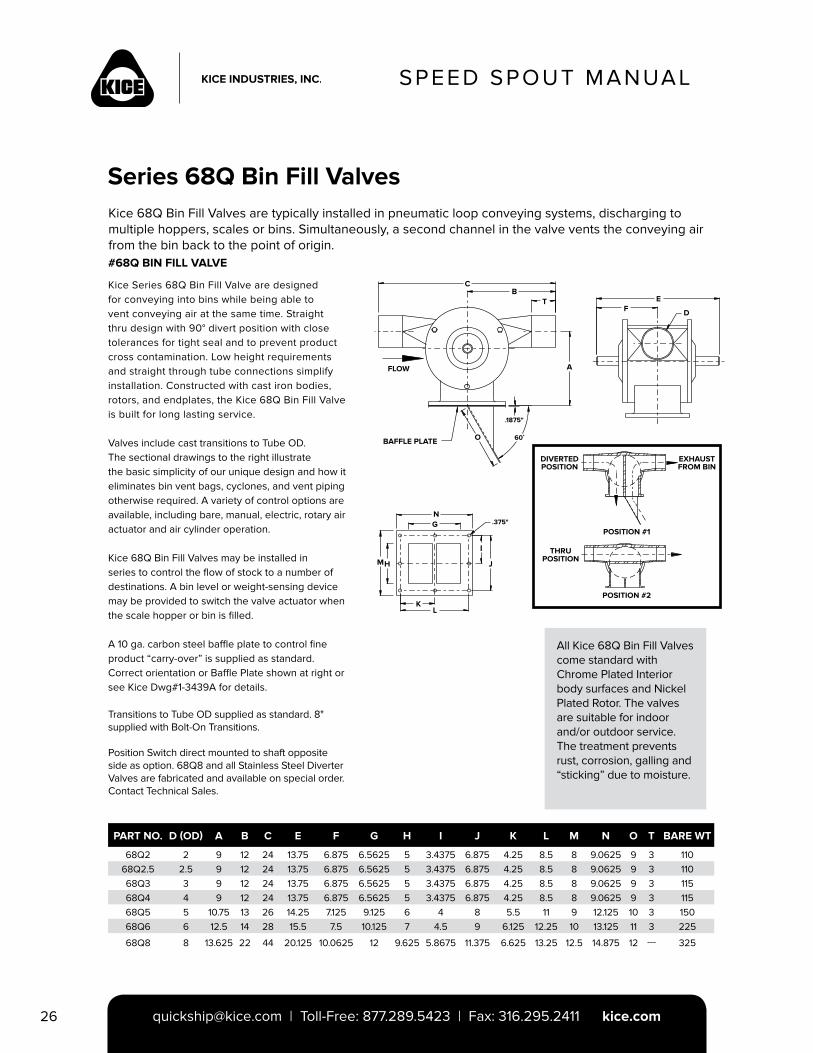
Kice 68Q Bin Fill Valves are typically installed in pneumatic loop conveying systems, discharging to multiple hoppers, scales or bins. Simultaneously, a second channel in the valve vents the conveying air from the bin back to the point of origin.
PART NO. D (OD) A B C E F G H I J K L M N O T BARE WT
68Q2 2 9 12 24 13.75 6.875 6.5625 5 3.4375 6.875 4.25 8.5 8 9.0625 9 3 11068Q2.5 2.5 9 12 24 13.75 6.875 6.5625 5 3.4375 6.875 4.25 8.5 8 9.0625 9 3 11068Q3 3 9 12 24 13.75 6.875 6.5625 5 3.4375 6.875 4.25 8.5 8 9.0625 9 3 11568Q4 4 9 12 24 13.75 6.875 6.5625 5 3.4375 6.875 4.25 8.5 8 9.0625 9 3 11568Q5 5 10.75 13 26 14.25 7.125 9.125 6 4 8 5.5 11 9 12.125 10 3 15068Q6 6 12.5 14 28 15.5 7.5 10.125 7 4.5 9 6.125 12.25 10 13.125 11 3 225
68Q8 8 13.625 22 44 20.125 10.0625 12 9.625 5.8675 11.375 6.625 13.25 12.5 14.875 12 --- 325
Kice Series 68Q Bin Fill Valve are designed for conveying into bins while being able to vent conveying air at the same time. Straight thru design with 90° divert position with close tolerances for tight seal and to prevent product cross contamination. Low height requirements and straight through tube connections simplify installation. Constructed with cast iron bodies, rotors, and endplates, the Kice 68Q Bin Fill Valve is built for long lasting service.
Valves include cast transitions to Tube OD. The sectional drawings to the right illustrate the basic simplicity of our unique design and how it eliminates bin vent bags, cyclones, and vent piping otherwise required. A variety of control options are available, including bare, manual, electric, rotary air actuator and air cylinder operation.
Kice 68Q Bin Fill Valves may be installed in series to control the flow of stock to a number of destinations. A bin level or weight-sensing device may be provided to switch the valve actuator when the scale hopper or bin is filled.
A 10 ga. carbon steel baffle plate to control fine product “carry-over” is supplied as standard. Correct orientation or Baffle Plate shown at right or see Kice Dwg#1-3439A for details.
Transitions to Tube OD supplied as standard. 8" supplied with Bolt-On Transitions.
Position Switch direct mounted to shaft opposite side as option. 68Q8 and all Stainless Steel Diverter Valves are fabricated and available on special order. Contact Technical Sales.
Series 68Q Bin Fill Valves
#68Q BIN FILL VALVE
CB
T
AFLOW
BAFFLE PLATE O
.1875"
60˚
EF D
NG
MH
KL
J
.375"
DIVERTEDPOSITION
EXHAUSTFROM BIN
POSITION #1
POSITION #2
THRUPOSITION
All Kice 68Q Bin Fill Valves come standard with Chrome Plated Interior body surfaces and Nickel Plated Rotor. The valves are suitable for indoor and/or outdoor service. The treatment prevents rust, corrosion, galling and “sticking” due to moisture.
SPEED SPOUT MANUAL
[email protected] | Toll-Free: 877.289.5423 | Fax: 316.295.2411 kice.com 27
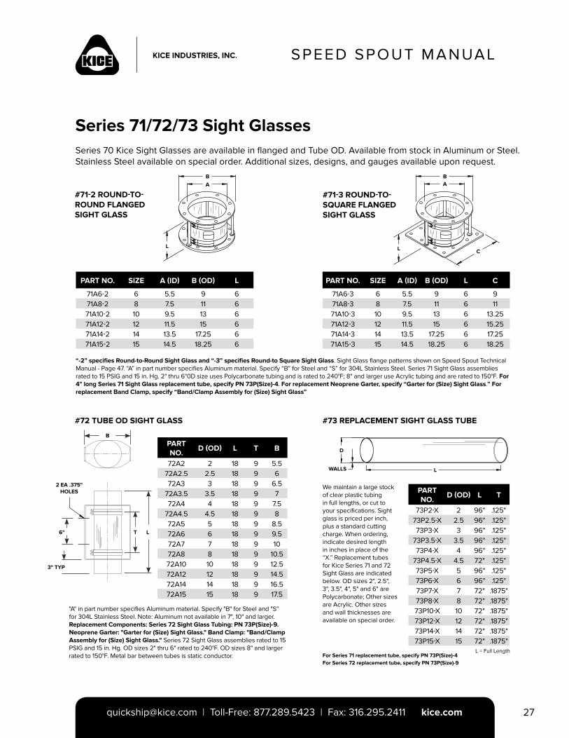
Series 71/72/73 Sight GlassesSeries 70 Kice Sight Glasses are available in flanged and Tube OD. Available from stock in Aluminum or Steel. Stainless Steel available on special order. Additional sizes, designs, and gauges available upon request.
#72 TUBE OD SIGHT GLASS #73 REPLACEMENT SIGHT GLASS TUBE
#71-3 ROUND-TO-SQUARE FLANGED SIGHT GLASS
PART NO.
D (OD) L T B
72A2 2 18 9 5.572A2.5 2.5 18 9 672A3 3 18 9 6.5
72A3.5 3.5 18 9 772A4 4 18 9 7.5
72A4.5 4.5 18 9 872A5 5 18 9 8.572A6 6 18 9 9.572A7 7 18 9 1072A8 8 18 9 10.572A10 10 18 9 12.572A12 12 18 9 14.572A14 14 18 9 16.572A15 15 18 9 17.5
PART NO.
D (OD) L T
73P2-X 2 96" .125"73P2.5-X 2.5 96" .125"73P3-X 3 96" .125"
73P3.5-X 3.5 96" .125"73P4-X 4 96" .125"
73P4.5-X 4.5 72" .125"73P5-X 5 96" .125"73P6-X 6 96" .125"73P7-X 7 72" .1875"73P8-X 8 72" .1875"73P10-X 10 72" .1875"73P12-X 12 72" .1875"73P14-X 14 72" .1875"73P15-X 15 72" .1875"
PART NO. SIZE A (ID) B (OD) L
71A6-2 6 5.5 9 671A8-2 8 7.5 11 671A10-2 10 9.5 13 671A12-2 12 11.5 15 671A14-2 14 13.5 17.25 671A15-2 15 14.5 18.25 6
#71-2 ROUND-TO-ROUND FLANGED SIGHT GLASS
PART NO. SIZE A (ID) B (OD) L C
71A6-3 6 5.5 9 6 971A8-3 8 7.5 11 6 1171A10-3 10 9.5 13 6 13.2571A12-3 12 11.5 15 6 15.2571A14-3 14 13.5 17.25 6 17.2571A15-3 15 14.5 18.25 6 18.25
“-2” specifies Round-to-Round Sight Glass and “-3” specifies Round-to Square Sight Glass. Sight Glass flange patterns shown on Speed Spout Technical Manual - Page 47. “A” in part number specifies Aluminum material. Specify “B” for Steel and “S” for 304L Stainless Steel. Series 71 Sight Glass assemblies rated to 15 PSIG and 15 in. Hg. 2" thru 6"0D size uses Polycarbonate tubing and is rated to 240°F; 8" and larger use Acrylic tubing and are rated to 150°F. For 4" long Series 71 Sight Glass replacement tube, specify PN 73P(Size)-4. For replacement Neoprene Garter, specify “Garter for (Size) Sight Glass.” For replacement Band Clamp, specify “Band/Clamp Assembly for (Size) Sight Glass”
"A" in part number specifies Aluminum material. Specify "B" for Steel and "S" for 304L Stainless Steel. Note: Aluminum not available in 7", 10" and larger. Replacement Components: Series 72 Sight Glass Tubing: PN 73P(Size)-9. Neoprene Garter: "Garter for (Size) Sight Glass." Band Clamp: "Band/Clamp Assembly for (Size) Sight Glass." Series 72 Sight Glass assemblies rated to 15 PSIG and 15 in. Hg. OD sizes 2" thru 6" rated to 240°F. OD sizes 8" and larger rated to 150°F. Metal bar between tubes is static conductor.
We maintain a large stock of clear plastic tubing in full lengths, or cut to your specifications. Sight glass is priced per inch, plus a standard cutting charge. When ordering, indicate desired length in inches in place of the “X.” Replacement tubes for Kice Series 71 and 72 Sight Glass are indicated below. OD sizes 2", 2.5", 3", 3.5", 4", 5" and 6" are Polycarbonate; Other sizes are Acrylic. Other sizes and wall thicknesses are available on special order.
For Series 71 replacement tube, specify PN 73P(Size)-4For Series 72 replacement tube, specify PN 73P(Size)-9
L = Full Length
BA
L C
BA
L
WALLS
D
L
2 EA .375" HOLES
3" TYP
6" T
B
L
SPEED SPOUT MANUAL
[email protected] | Toll-Free: 877.289.5423 | Fax: 316.295.2411 kice.com28
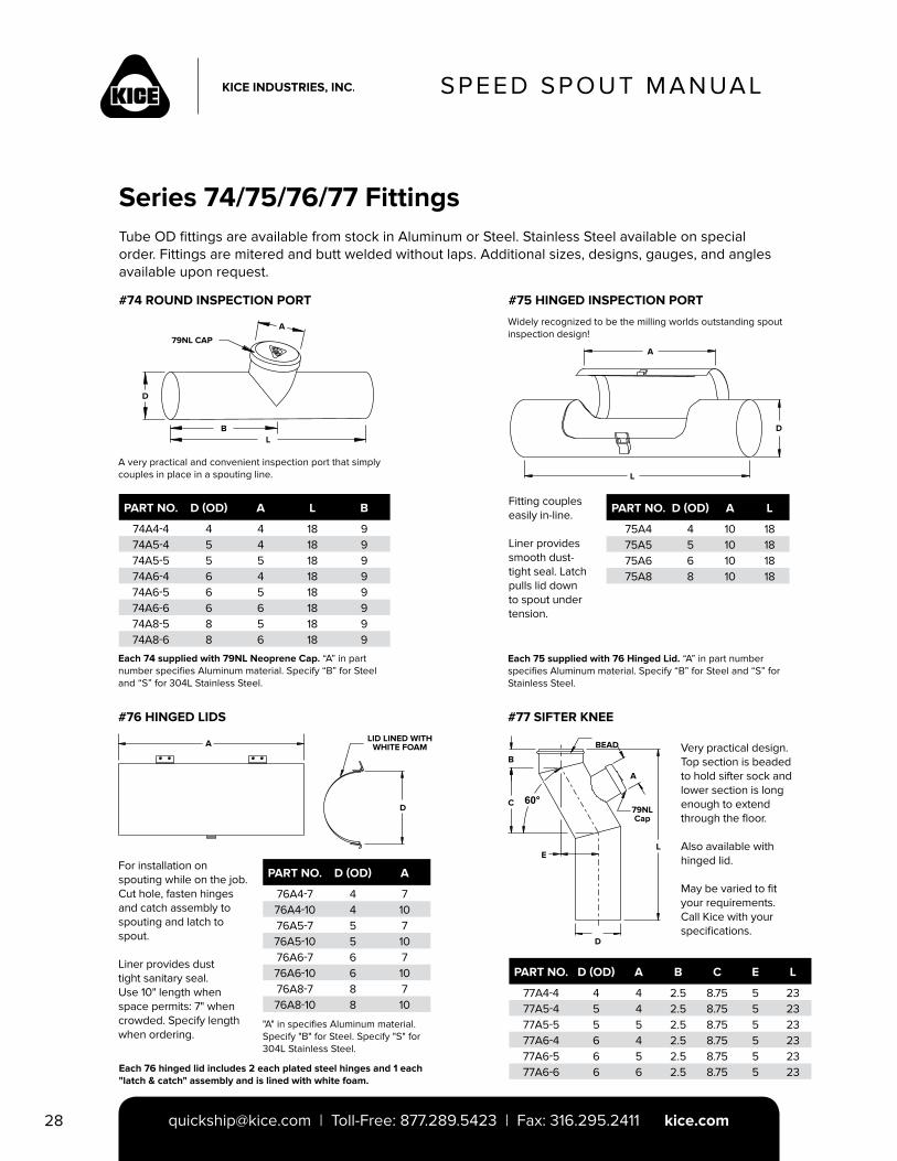
Series 74/75/76/77 FittingsTube OD fittings are available from stock in Aluminum or Steel. Stainless Steel available on special order. Fittings are mitered and butt welded without laps. Additional sizes, designs, gauges, and angles available upon request.
#74 ROUND INSPECTION PORT #75 HINGED INSPECTION PORT
PART NO. D (OD) A L B
74A4-4 4 4 18 974A5-4 5 4 18 974A5-5 5 5 18 974A6-4 6 4 18 974A6-5 6 5 18 974A6-6 6 6 18 974A8-5 8 5 18 974A8-6 8 6 18 9
PART NO. D (OD) A L
75A4 4 10 1875A5 5 10 1875A6 6 10 1875A8 8 10 18
A
D
BL
79NL CAP
Each 74 supplied with 79NL Neoprene Cap. “A” in part number specifies Aluminum material. Specify “B” for Steel and “S” for 304L Stainless Steel.
Each 75 supplied with 76 Hinged Lid. “A” in part number specifies Aluminum material. Specify “B” for Steel and “S” for Stainless Steel.
Widely recognized to be the milling worlds outstanding spout inspection design!
A
L
D
A very practical and convenient inspection port that simply couples in place in a spouting line.
Fitting couples easily in-line.
Liner provides smooth dust-tight seal. Latch pulls lid down to spout under tension.
#76 HINGED LIDS #77 SIFTER KNEE
A
D
LID LINED WITH WHITE FOAM
B
C
E
D
L
A
BEAD
79NLCap
Very practical design. Top section is beaded to hold sifter sock and lower section is long enough to extend through the floor.
Also available with hinged lid.
May be varied to fit your requirements. Call Kice with your specifications.
PART NO. D (OD) A B C E L
77A4-4 4 4 2.5 8.75 5 2377A5-4 5 4 2.5 8.75 5 2377A5-5 5 5 2.5 8.75 5 2377A6-4 6 4 2.5 8.75 5 2377A6-5 6 5 2.5 8.75 5 2377A6-6 6 6 2.5 8.75 5 23
For installation on spouting while on the job. Cut hole, fasten hinges and catch assembly to spouting and latch to spout.
Liner provides dust tight sanitary seal. Use 10" length when space permits: 7" when crowded. Specify length when ordering.
PART NO. D (OD) A
76A4-7 4 776A4-10 4 1076A5-7 5 776A5-10 5 1076A6-7 6 776A6-10 6 1076A8-7 8 776A8-10 8 10
"A" in specifies Aluminum material. Specify "B" for Steel. Specify "S" for 304L Stainless Steel.
Each 76 hinged lid includes 2 each plated steel hinges and 1 each "latch & catch" assembly and is lined with white foam.
SPEED SPOUT MANUAL
[email protected] | Toll-Free: 877.289.5423 | Fax: 316.295.2411 kice.com 29
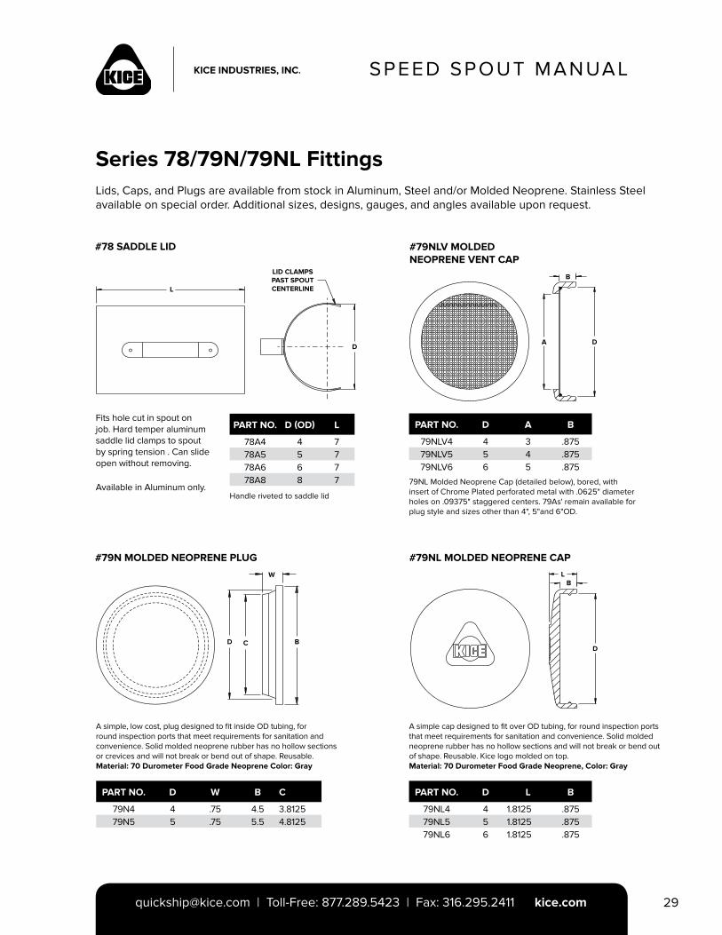
Series 78/79N/79NL FittingsLids, Caps, and Plugs are available from stock in Aluminum, Steel and/or Molded Neoprene. Stainless Steel available on special order. Additional sizes, designs, gauges, and angles available upon request.
#79N MOLDED NEOPRENE PLUG #79NL MOLDED NEOPRENE CAP
#79NLV MOLDED NEOPRENE VENT CAP
PART NO. D (OD) L
78A4 4 778A5 5 778A6 6 778A8 8 7
#78 SADDLE LID
A simple, low cost, plug designed to fit inside OD tubing, for round inspection ports that meet requirements for sanitation and convenience. Solid molded neoprene rubber has no hollow sections or crevices and will not break or bend out of shape. Reusable. Material: 70 Durometer Food Grade Neoprene Color: Gray
A simple cap designed to fit over OD tubing, for round inspection ports that meet requirements for sanitation and convenience. Solid molded neoprene rubber has no hollow sections and will not break or bend out of shape. Reusable. Kice logo molded on top.Material: 70 Durometer Food Grade Neoprene, Color: Gray
Fits hole cut in spout on job. Hard temper aluminum saddle lid clamps to spout by spring tension . Can slide open without removing.
Available in Aluminum only.Handle riveted to saddle lid
79NL Molded Neoprene Cap (detailed below), bored, withinsert of Chrome Plated perforated metal with .0625" diameter holes on .09375" staggered centers. 79As' remain available for plug style and sizes other than 4", 5"and 6"OD.
PART NO. D A B
79NLV4 4 3 .87579NLV5 5 4 .87579NLV6 6 5 .875
PART NO. D W B C
79N4 4 .75 4.5 3.812579N5 5 .75 5.5 4.8125
PART NO. D L B
79NL4 4 1.8125 .87579NL5 5 1.8125 .87579NL6 6 1.8125 .875
L
D
LID CLAMPS PAST SPOUT CENTERLINE
B
A D
W
D C BD
LB
SPEED SPOUT MANUAL
[email protected] | Toll-Free: 877.289.5423 | Fax: 316.295.2411 kice.com30
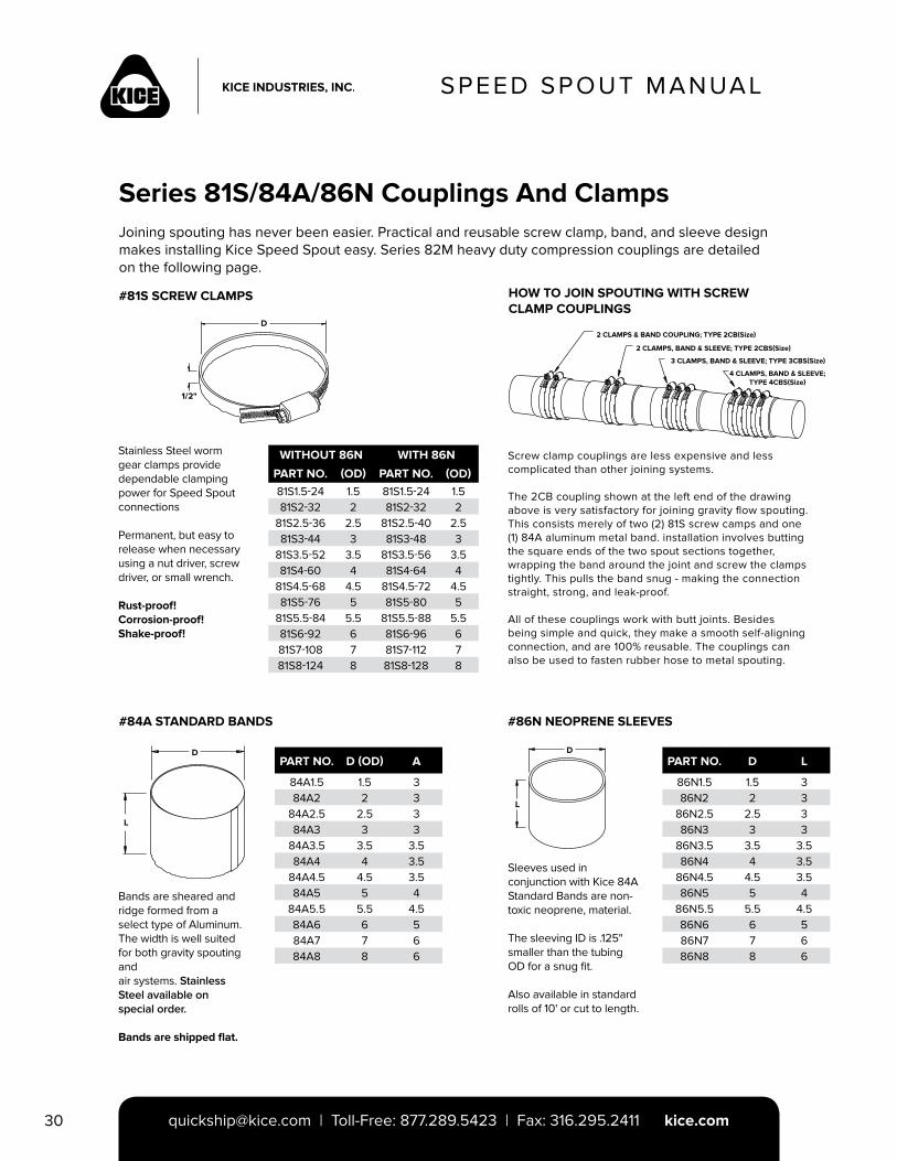
Series 81S/84A/86N Couplings And ClampsJoining spouting has never been easier. Practical and reusable screw clamp, band, and sleeve design makes installing Kice Speed Spout easy. Series 82M heavy duty compression couplings are detailed on the following page.
#81S SCREW CLAMPS HOW TO JOIN SPOUTING WITH SCREW CLAMP COUPLINGS
WITHOUT 86N WITH 86N
PART NO. (OD) PART NO. (OD)81S1.5-24 1.5 81S1.5-24 1.581S2-32 2 81S2-32 2
81S2.5-36 2.5 81S2.5-40 2.581S3-44 3 81S3-48 3
81S3.5-52 3.5 81S3.5-56 3.581S4-60 4 81S4-64 4
81S4.5-68 4.5 81S4.5-72 4.581S5-76 5 81S5-80 5
81S5.5-84 5.5 81S5.5-88 5.581S6-92 6 81S6-96 681S7-108 7 81S7-112 781S8-124 8 81S8-128 8
#84A STANDARD BANDS #86N NEOPRENE SLEEVES
Sleeves used in conjunction with Kice 84A Standard Bands are non-toxic neoprene, material.
The sleeving ID is .125" smaller than the tubing OD for a snug fit.
Also available in standard rolls of 10' or cut to length.
Bands are sheared and ridge formed from a select type of Aluminum. The width is well suited for both gravity spouting and air systems. Stainless Steel available on special order.
Bands are shipped flat.
PART NO. D (OD) A
84A1.5 1.5 384A2 2 3
84A2.5 2.5 384A3 3 3
84A3.5 3.5 3.584A4 4 3.5
84A4.5 4.5 3.584A5 5 4
84A5.5 5.5 4.584A6 6 584A7 7 684A8 8 6
Stainless Steel worm gear clamps provide dependable clamping power for Speed Spout connections
Permanent, but easy to release when necessary using a nut driver, screw driver, or small wrench.
Rust-proof! Corrosion-proof! Shake-proof!
2 CLAMPS & BAND COUPLING; TYPE 2CB(Size)
2 CLAMPS, BAND & SLEEVE; TYPE 2CBS(Size)
3 CLAMPS, BAND & SLEEVE; TYPE 3CBS(Size)
4 CLAMPS, BAND & SLEEVE; TYPE 4CBS(Size)
Screw clamp couplings are less expensive and less complicated than other joining systems.
The 2CB coupling shown at the left end of the drawing above is very satisfactory for joining gravity flow spouting. This consists merely of two (2) 81S screw camps and one (1) 84A aluminum metal band. installation involves butting the square ends of the two spout sections together, wrapping the band around the joint and screw the clamps tightly. This pulls the band snug - making the connection straight, strong, and leak-proof.
All of these couplings work with butt joints. Besides being simple and quick, they make a smooth self-aligning connection, and are 100% reusable. The couplings can also be used to fasten rubber hose to metal spouting.
PART NO. D L
86N1.5 1.5 386N2 2 3
86N2.5 2.5 386N3 3 3
86N3.5 3.5 3.586N4 4 3.5
86N4.5 4.5 3.586N5 5 4
86N5.5 5.5 4.586N6 6 586N7 7 686N8 8 6
D
1/2"
D
L
D
L
SPEED SPOUT MANUAL
[email protected] | Toll-Free: 877.289.5423 | Fax: 316.295.2411 kice.com 31
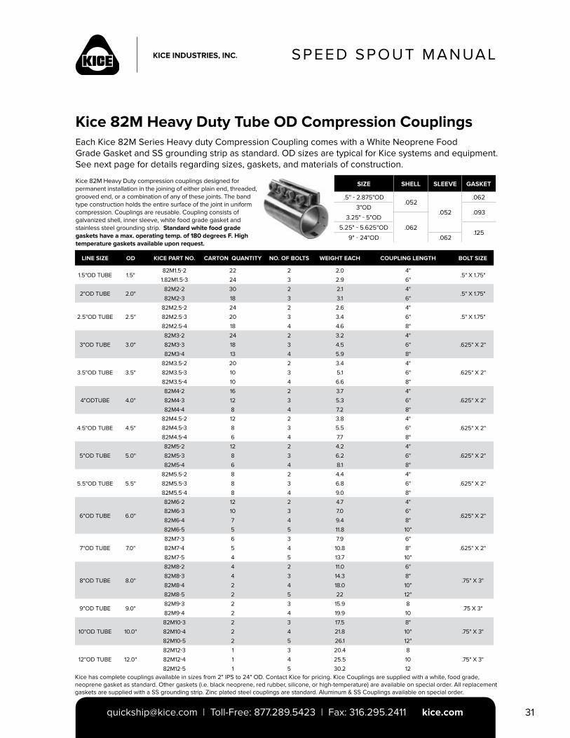
Kice 82M Heavy Duty Tube OD Compression CouplingsEach Kice 82M Series Heavy duty Compression Coupling comes with a White Neoprene FoodGrade Gasket and SS grounding strip as standard. OD sizes are typical for Kice systems and equipment.See next page for details regarding sizes, gaskets, and materials of construction.
Kice 82M Heavy Duty compression couplings designed for permanent installation in the joining of either plain end, threaded, grooved end, or a combination of any of these joints. The band type construction holds the entire surface of the joint in uniform compression. Couplings are reusable. Coupling consists of galvanized shell, inner sleeve, white food grade gasket and stainless steel grounding strip. Standard white food grade gaskets have a max. operating temp. of 180 degrees F. High temperature gaskets available upon request.
SIZE SHELL SLEEVE GASKET
.5'' - 2.875"OD.052
.052
.062
3"OD.093
3.25" - 5"OD
.0625.25" - 5.625"OD.125
9" - 24"OD .062
LINE SIZE OD KICE PART NO. CARTON QUANTITY NO. OF BOLTS WEIGHT EACH COUPLING LENGTH BOLT SIZE
1.5"OD TUBE 1.5"82M1.5-2 22 2 2.0 4"
.5" X 1.75"1.82M1.5-3 24 3 2.9 6"
2"OD TUBE 2.0"82M2-2 30 2 2.1 4"
.5" X 1.75"82M2-3 18 3 3.1 6"
2.5"OD TUBE 2.5"
82M2.5-2 24 2 2.6 4"
.5" X 1.75"82M2.5-3 20 3 3.4 6"
82M2.5-4 18 4 4.6 8"
3"OD TUBE 3.0"
82M3-2 24 2 3.2 4"
.625" X 2"82M3-3 18 3 4.5 6"
82M3-4 13 4 5.9 8"
3.5"OD TUBE 3.5"
82M3.5-2 20 2 3.4 4"
.625" X 2"82M3.5-3 10 3 5.1 6"
82M3.5-4 10 4 6.6 8"
4"ODTUBE 4.0"
82M4-2 16 2 3.7 4"
.625" X 2"82M4-3 12 3 5.3 6"
82M4-4 8 4 7.2 8"
4.5"OD TUBE 4.5"
82M4.5-2 12 2 3.8 4"
.625" X 2"82M4.5-3 8 3 5.5 6"
82M4.5-4 6 4 7.7 8"
5"OD TUBE 5.0"
82M5-2 12 2 4.2 4"
.625" X 2"82M5-3 8 3 6.2 6"
82M5-4 6 4 8.1 8"
5.5"OD TUBE 5.5"
82M5.5-2 8 2 4.4 4"
.625" X 2"82M5.5-3 8 3 6.8 6"
82M5.5-4 8 4 9.0 8"
6"OD TUBE 6.0"
82M6-2 12 2 4.7 4"
.625" X 2"82M6-3 10 3 7.0 6"
82M6-4 7 4 9.4 8"
82M6-5 5 5 11.8 10"
7"OD TUBE 7.0"
82M7-3 6 3 7.9 6"
.625" X 2"82M7-4 5 4 10.8 8"
82M7-5 4 5 13.7 10"
8"OD TUBE 8.0"
82M8-2 4 2 11.0 6"
.75" X 3"82M8-3 4 3 14.3 8"
82M8-4 2 4 18.0 10"
82M8-5 2 5 22 12"
9"OD TUBE 9.0"82M9-3 2 3 15.9 8
.75 X 3"82M9-4 2 4 19.9 10
10"OD TUBE 10.0"
82M10-3 2 3 17.5 8"
.75" X 3"82M10-4 2 4 21.8 10"
82M10-5 2 5 26.1 12"
12"OD TUBE 12.0"
82M12-3 1 3 20.4 8
.75" X 3"82M12-4 1 4 25.5 10
82M12-5 1 5 30.2 12Kice has complete couplings available in sizes from 2" IPS to 24" OD. Contact Kice for pricing. Kice Couplings are supplied with a white, food grade, neoprene gasket as standard. Other gaskets (i.e. black neoprene, red rubber, silicone, or high-temperature) are available on special order. All replacement gaskets are supplied with a SS grounding strip. Zinc plated steel couplings are standard. Aluminum & SS Couplings available on special order.
SPEED SPOUT MANUAL
[email protected] | Toll-Free: 877.289.5423 | Fax: 316.295.2411 kice.com32
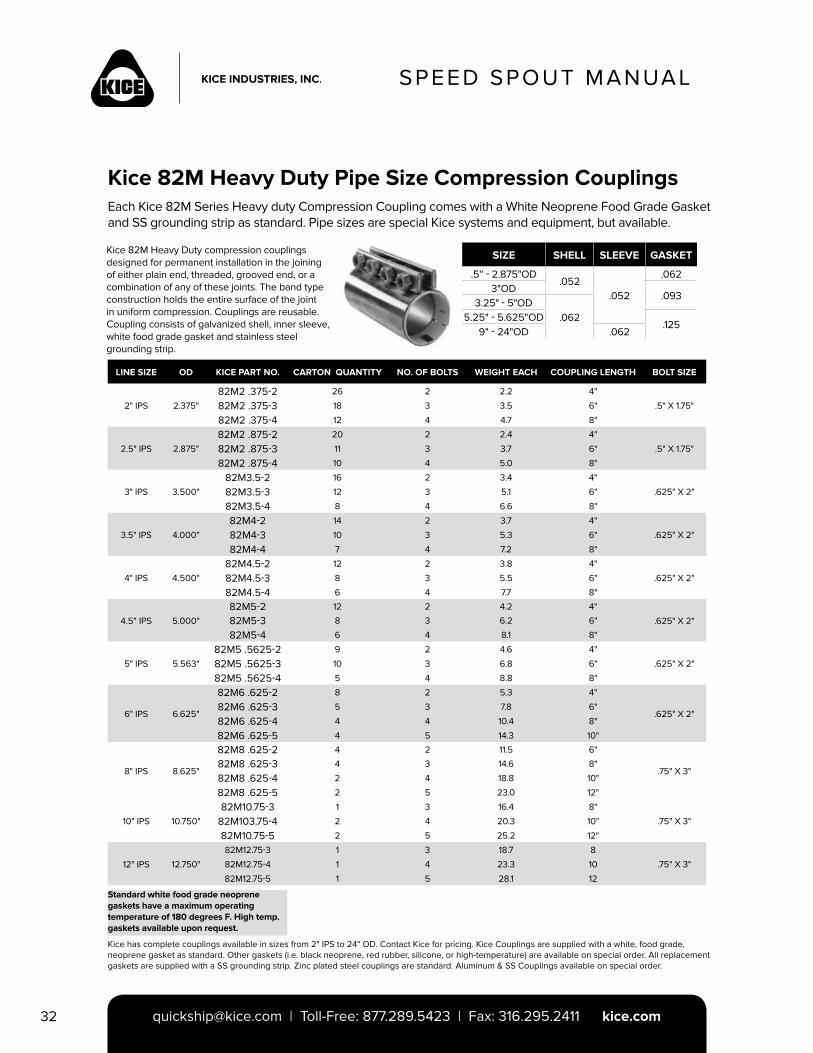
Kice 82M Heavy Duty Pipe Size Compression CouplingsEach Kice 82M Series Heavy duty Compression Coupling comes with a White Neoprene Food Grade Gasket and SS grounding strip as standard. Pipe sizes are special Kice systems and equipment, but available.
Kice 82M Heavy Duty compression couplings designed for permanent installation in the joining of either plain end, threaded, grooved end, or a combination of any of these joints. The band type construction holds the entire surface of the joint in uniform compression. Couplings are reusable. Coupling consists of galvanized shell, inner sleeve, white food grade gasket and stainless steel grounding strip.
SIZE SHELL SLEEVE GASKET
.5'' - 2.875"OD.052
.052
.0623"OD
.0933.25" - 5"OD
.0625.25" - 5.625"OD.125
9" - 24"OD .062
LINE SIZE OD KICE PART NO. CARTON QUANTITY NO. OF BOLTS WEIGHT EACH COUPLING LENGTH BOLT SIZE
2" IPS 2.375"
82M2 .375-2 26 2 2.2 4"
.5" X 1.75"82M2 .375-3 18 3 3.5 6"
82M2 .375-4 12 4 4.7 8"
2.5" IPS 2.875"
82M2 .875-2 20 2 2.4 4"
.5" X 1.75"82M2 .875-3 11 3 3.7 6"
82M2 .875-4 10 4 5.0 8"
3" IPS 3.500"
82M3.5-2 16 2 3.4 4"
.625" X 2"82M3.5-3 12 3 5.1 6"
82M3.5-4 8 4 6.6 8"
3.5" IPS 4.000"
82M4-2 14 2 3.7 4"
.625" X 2"82M4-3 10 3 5.3 6"
82M4-4 7 4 7.2 8"
4" IPS 4.500"
82M4.5-2 12 2 3.8 4"
.625" X 2"82M4.5-3 8 3 5.5 6"
82M4.5-4 6 4 7.7 8"
4.5" IPS 5.000"
82M5-2 12 2 4.2 4"
.625" X 2"82M5-3 8 3 6.2 6"
82M5-4 6 4 8.1 8"
5" IPS 5.563"
82M5 .5625-2 9 2 4.6 4"
.625" X 2"82M5 .5625-3 10 3 6.8 6"
82M5 .5625-4 5 4 8.8 8"
6" IPS 6.625"
82M6 .625-2 8 2 5.3 4"
.625" X 2"82M6 .625-3 5 3 7.8 6"
82M6 .625-4 4 4 10.4 8"
82M6 .625-5 4 5 14.3 10"
8" IPS 8.625"
82M8 .625-2 4 2 11.5 6"
.75" X 3"82M8 .625-3 4 3 14.6 8"
82M8 .625-4 2 4 18.8 10"
82M8 .625-5 2 5 23.0 12"
10" IPS 10.750"
82M10.75-3 1 3 16.4 8"
.75" X 3"82M103.75-4 2 4 20.3 10"
82M10.75-5 2 5 25.2 12"
12" IPS 12.750"
82M12.75-3 1 3 18.7 8
.75" X 3"82M12.75-4 1 4 23.3 10
82M12.75-5 1 5 28.1 12
Kice has complete couplings available in sizes from 2" IPS to 24" OD. Contact Kice for pricing. Kice Couplings are supplied with a white, food grade, neoprene gasket as standard. Other gaskets (i.e. black neoprene, red rubber, silicone, or high-temperature) are available on special order. All replacement gaskets are supplied with a SS grounding strip. Zinc plated steel couplings are standard. Aluminum & SS Couplings available on special order.
Standard white food grade neoprene gaskets have a maximum operating temperature of 180 degrees F. High temp. gaskets available upon request.
SPEED SPOUT MANUAL
[email protected] | Toll-Free: 877.289.5423 | Fax: 316.295.2411 kice.com 33
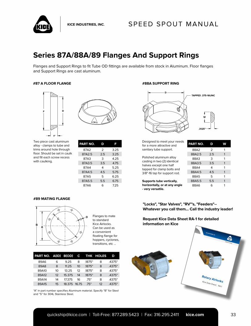
Series 87A/88A/89 Flanges And Support RingsFlanges and Support Rings to fit Tube OD fittings are available from stock in Aluminum. Floor flanges and Support Rings are cast aluminum.
#87 A FLOOR FLANGE #88A SUPPORT RING
Two piece cast aluminumalloy - clamps to tube andtrims around hole throughfloor. Should be set in caulkand fill each screw recesswith caulking.
PART NO. D F
87A2 2 3.2587A2.5 2.5 3.2587A3 3 4.25
87A3.5 3.5 4.7587A4 4 5.25
87A4.5 4.5 5.7587A5 5 6.25
87A5.5 5.5 6.7587A6 6 7.25
Designed to meet your needsfor a more attractive and sanitary tube support.
Polished aluminum alloy casting in two (2) identical halves except one half tapped for clamp bolts and 3/8"-16 tap for support rod.
Supports tube vertically, horizontally, or at any angle - very versatile.
PART NO. D W
88A2 2 188A2.5 2.5 188A3 3 1
88A3.5 3.5 188A4 4 1
88A4.5 4.5 188A5 5 1
88A5.5 5.5 188A6 6 1
F D
1"
D
W
.3125"
TAPPED .375-16UNC
#89 MATING FLANGE
Flanges to mate to standard Kice Airlocks. Can be used as a convenient floating flange for hoppers, cyclones, transitions, etc ...
PART NO. A(ID) B(OD) C THK HOLES D
89A6 6 9.25 8 .1875" 8 .4375"89A8 8 11.25 10 .1875" 8 .4375"89A10 10 13.25 12 .1875" 8 .4375"89A12 12 15.375 14 .1875" 8 .4375"89A14 14 17.375 16 .75" 8 .4375"89A15 15 18.375 16.75 .75" 12 .4375"
“A” in part number specifies Aluminum material. Specify “B” for Steel and “S” for 304L Stainless Steel.
"Locks", "Star Valves", "RV"'s, "Feeders"-- Whatever you call them... Call the industry leader!
Request Kice Data Sheet RA-1 for detailed information on Kice
SPEED SPOUT MANUAL
[email protected] | Toll-Free: 877.289.5423 | Fax: 316.295.2411 kice.com34
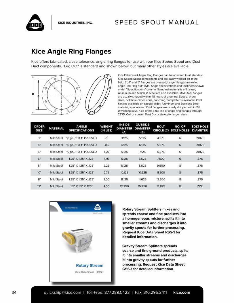
Kice Angle Ring FlangesKice offers fabricated, close tolerance, angle ring flanges for use with our Kice Speed Spout and Dust Duct components. "Leg Out" is standard and shown below, but many other styles are available.
ORDER SIZE
MATERIALANGLE
SPECIFICATIONSWEIGHT (IN LBS)
INSIDE DIAMETER
(A)
OUTSIDE DIAMETER
(B)
BOLT CIRCLE (C)
NO. OF BOLT HOLES
BOLT HOLE DIAMETER
3" Mild Steel 10 ga., 1" X 1", PRESSED .70 3.125 5.125 4.375 6 .28125
4" Mild Steel 10 ga., 1" X 1", PRESSED .85 4.125 6.125 5.375 6 .28125
5" Mild Steel 10 ga., 1" X 1", PRESSED 1.20 5.125 7.125 6.375 6 .28125
6" Mild Steel 1.25" X 1.25" X .125" 1.75 6.125 8.625 7.500 6 .375
8" Mild Steel 1.25" X 1.25" X .125" 2.25 8.125 8.625 9.500 8 .375
10" Mild Steel 1.25" X 1.25" X .125" 2.75 10.125 10.625 11.500 8 .375
11" Mild Steel 1.25" X 1.25" X .125" 3.00 11.125 11.625 12.500 8 .375
12" Mild Steel 1.5" X 1.5" X .125" 4.00 12.250 15.250 13.875 12 ZZZ
Kice Fabricated Angle Ring Flanges can be attached to all standard Kice Speed Spout components and are easily welded on in the field. 3", 4" and 5" flanges are pressed; Larger flanges are rolled angle iron, "leg out" style. Angle specifications and thickness shown under "Specifications" column. Standard material is mild steel; Aluminum and Stainless Steel are also available. Mild Steel flanges are usually shipped within 48 hours of ordering. Special order sizes, bolt hole dimensions, punching, and patterns available. Oval flanges available on special order. Aluminum and Stainless Steel material, specials and Oval flanges are usually shipped within 7-1 0 working days. Kice offers a full line of angle ring flanges through 72"ID. Call or consult Dust Duct catalog for larger sizes.
Rotary Stream Splitters mixes and spreads coarse and fine products into a homogeneous mixture, splits it into smaller streams and discharges it into gravity spouts for further processing. Request Kice Data Sheet RSS-1 for detailed information.
Gravity Stream Splitters spreads coarse and fine ground products, splits it into smaller streams and discharges it into gravity spouts for further processing. Request Kice Data Sheet GSS-1 for detailed information.
SPEED SPOUT MANUAL
[email protected] | Toll-Free: 877.289.5423 | Fax: 316.295.2411 kice.com 35
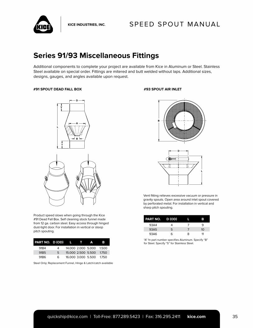
Series 91/93 Miscellaneous FittingsAdditional components to complete your project are available from Kice in Aluminum or Steel. Stainless Steel available on special order. Fittings are mitered and butt welded without laps. Additional sizes, designs, gauges, and angles available upon request.
Product speed slows when going through the Kice #91 Dead Fall Box. Self cleaning stock funnel made from 12 ga. carbon steel. Easy access through hinged dust-tight door. For installation in vertical or steep pitch spouting.
PART NO. D (OD) L T A B
91B4 4 14.000 2.000 5.000 1.50091B5 5 15.000 2.500 5.500 1.75091B6 6 16.000 3.000 5.500 1.750
#93 SPOUT AIR INLET
Vent fitting relieves excessive vacuum or pressure in gravity spouts. Open area around inlet spout covered by perforated metal. For installation in vertical and sharp pitch spouting.
PART NO. D (OD) L B
93A4 4 7 993A5 5 7 1093A6 6 8 11
“A” 1n part number specifies Aluminum. Specify “B” for Steel. Specify “S” for Stainless Steel.
#91 SPOUT DEAD FALL BOX
L
D
A
B
T
B
D
L
Steel Only; Replacement Funnel, Hinge & Latch/catch available
SPEED SPOUT MANUAL
[email protected] | Toll-Free: 877.289.5423 | Fax: 316.295.2411 kice.com36
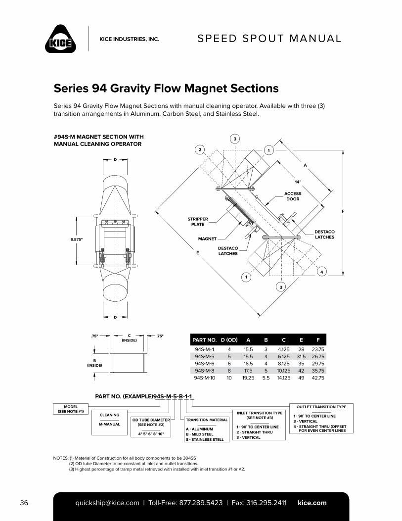
Series 94 Gravity Flow Magnet SectionsSeries 94 Gravity Flow Magnet Sections with manual cleaning operator. Available with three (3) transition arrangements in Aluminum, Carbon Steel, and Stainless Steel.
#94S-M MAGNET SECTION WITH MANUAL CLEANING OPERATOR
PART NO. D (OD) A B C E F
94S-M-4 4 15.5 3 4.125 28 23.7594S-M-5 5 15.5 4 6.125 31.5 26.7594S-M-6 6 16.5 4 8.125 35 29.7594S-M-8 8 17.5 5 10.125 42 35.7594S-M-10 10 19.25 5.5 14.125 49 42.75
D
D
9.875"
2
3
1
A
F
4
3
1
E
STRIPPER PLATE
MAGNET
DESTACOLATCHES
ACCESSDOOR
DESTACOLATCHES
14"
.75" .75"C(INSIDE)
B(INSIDE)
PART NO. (EXAMPLE)94S-M-5-B-1-1
MODEL(SEE NOTE #1)
CLEANING__________
M-MANUALOD TUBE DIAMETER
(SEE NOTE #2)__________
4" 5" 6" 8" 10"
TRANSITION MATERIAL__________
A - ALUMINUMB - MILD STEELS - STAINLESS STELL
INLET TRANSITION TYPE (SEE NOTE #3)
__________
1 - 90˚ TO CENTER LINE2 - STRAIGHT THRU3 - VERTICAL
OUTLET TRANSITION TYPE__________
1 - 90˚ TO CENTER LINE3 - VERTICAL4 - STRAIGHT THRU (OFFSET FOR EVEN CENTER LINES
NOTES: (1) Material of Construction for all body components to be 304SS (2) OD tube Diameter to be constant at inlet and outlet transitions. (3) Highest percentage of tramp metal retrieved with installed with inlet transition #1 or #2.
SPEED SPOUT MANUAL
[email protected] | Toll-Free: 877.289.5423 | Fax: 316.295.2411 kice.com 37
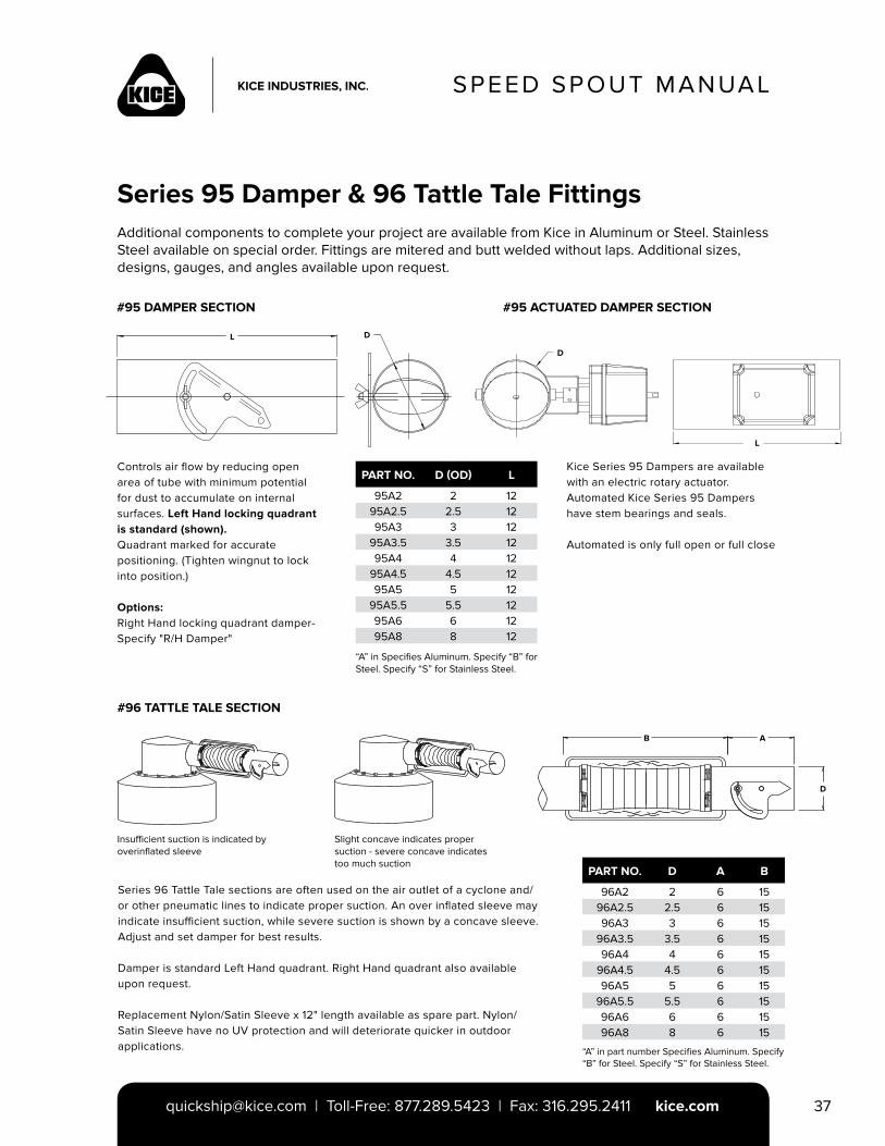
Series 95 Damper & 96 Tattle Tale FittingsAdditional components to complete your project are available from Kice in Aluminum or Steel. Stainless Steel available on special order. Fittings are mitered and butt welded without laps. Additional sizes, designs, gauges, and angles available upon request.
#95 DAMPER SECTION #95 ACTUATED DAMPER SECTION
PART NO. D (OD) L
95A2 2 1295A2.5 2.5 1295A3 3 12
95A3.5 3.5 1295A4 4 12
95A4.5 4.5 1295A5 5 12
95A5.5 5.5 1295A6 6 1295A8 8 12
Controls air flow by reducing open area of tube with minimum potential for dust to accumulate on internal surfaces. Left Hand locking quadrant is standard (shown).Quadrant marked for accurate positioning. (Tighten wingnut to lock into position.)
Options:Right Hand locking quadrant damper-Specify "R/H Damper"
Kice Series 95 Dampers are availablewith an electric rotary actuator. Automated Kice Series 95 Dampers have stem bearings and seals.
Automated is only full open or full close
“A” in Specifies Aluminum. Specify “B” for Steel. Specify “S” for Stainless Steel.
#96 TATTLE TALE SECTION
Insufficient suction is indicated by overinflated sleeve
Slight concave indicates proper suction - severe concave indicates too much suction
B A
D
Series 96 Tattle Tale sections are often used on the air outlet of a cyclone and/or other pneumatic lines to indicate proper suction. An over inflated sleeve may indicate insufficient suction, while severe suction is shown by a concave sleeve. Adjust and set damper for best results.
Damper is standard Left Hand quadrant. Right Hand quadrant also available upon request.
Replacement Nylon/Satin Sleeve x 12" length available as spare part. Nylon/Satin Sleeve have no UV protection and will deteriorate quicker in outdoor applications.
PART NO. D A B
96A2 2 6 1596A2.5 2.5 6 1596A3 3 6 15
96A3.5 3.5 6 1596A4 4 6 15
96A4.5 4.5 6 1596A5 5 6 15
96A5.5 5.5 6 1596A6 6 6 1596A8 8 6 15
“A” in part number Specifies Aluminum. Specify “B” for Steel. Specify “S” for Stainless Steel.
D
L
DL
SPEED SPOUT MANUAL
[email protected] | Toll-Free: 877.289.5423 | Fax: 316.295.2411 kice.com38
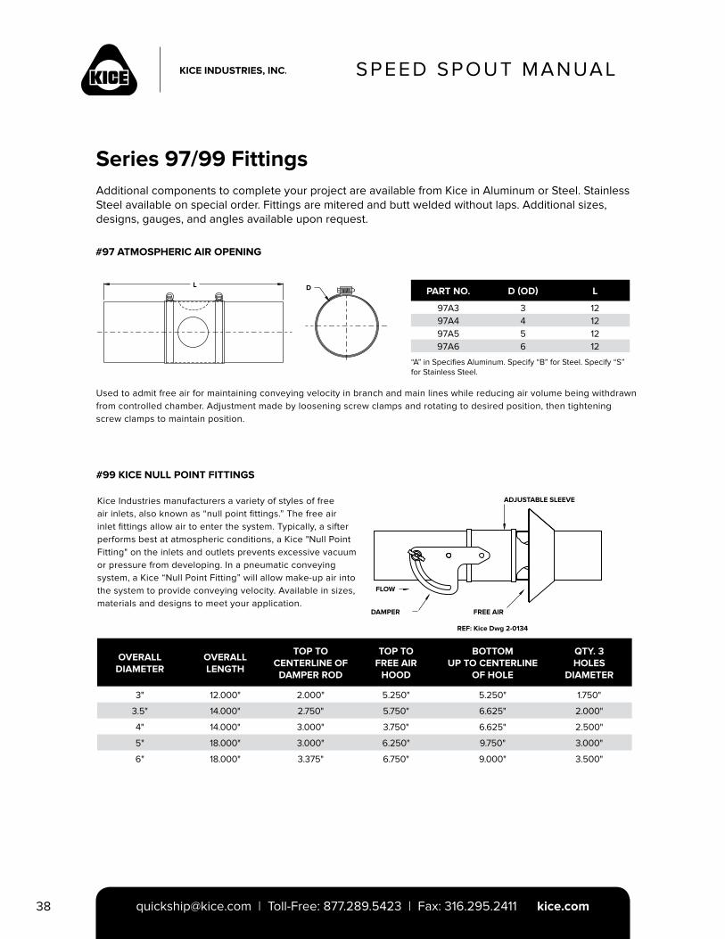
Series 97/99 FittingsAdditional components to complete your project are available from Kice in Aluminum or Steel. Stainless Steel available on special order. Fittings are mitered and butt welded without laps. Additional sizes, designs, gauges, and angles available upon request.
#97 ATMOSPHERIC AIR OPENING
#99 KICE NULL POINT FITTINGS
PART NO. D (OD) L
97A3 3 1297A4 4 1297A5 5 1297A6 6 12
Used to admit free air for maintaining conveying velocity in branch and main lines while reducing air volume being withdrawn from controlled chamber. Adjustment made by loosening screw clamps and rotating to desired position, then tightening screw clamps to maintain position.
“A” in Specifies Aluminum. Specify “B” for Steel. Specify “S” for Stainless Steel.
Kice Industries manufacturers a variety of styles of free air inlets, also known as “null point fittings.” The free air inlet fittings allow air to enter the system. Typically, a sifter performs best at atmospheric conditions, a Kice "Null Point Fitting" on the inlets and outlets prevents excessive vacuum or pressure from developing. In a pneumatic conveying system, a Kice “Null Point Fitting” will allow make-up air into the system to provide conveying velocity. Available in sizes, materials and designs to meet your application.
OVERALLDIAMETER
OVERALL LENGTH
TOP TO CENTERLINE OF
DAMPER ROD
TOP TO FREE AIR
HOOD
BOTTOM UP TO CENTERLINE
OF HOLE
QTY. 3 HOLES
DIAMETER
3" 12.000" 2.000" 5.250" 5.250" 1.750"
3.5" 14.000" 2.750" 5.750" 6.625" 2.000"
4" 14.000" 3.000" 3.750" 6.625" 2.500"
5" 18.000" 3.000" 6.250" 9.750" 3.000"
6" 18.000" 3.375" 6.750" 9.000" 3.500"
L D
FREE AIR
FLOW
ADJUSTABLE SLEEVE
REF: Kice Dwg 2-0134
DAMPER
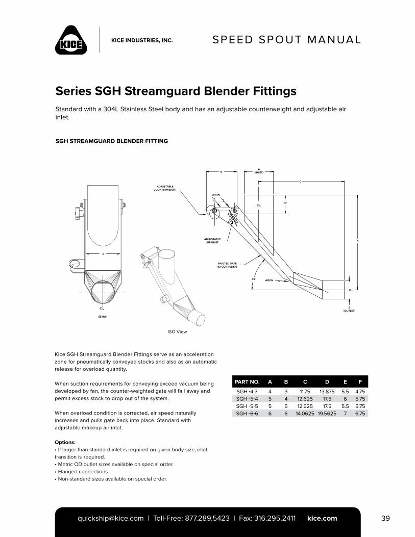
SPEED SPOUT MANUAL
[email protected] | Toll-Free: 877.289.5423 | Fax: 316.295.2411 kice.com 39
Series SGH Streamguard Blender FittingsStandard with a 304L Stainless Steel body and has an adjustable counterweight and adjustable air inlet.
SGH STREAMGUARD BLENDER FITTING
Kice SGH Streamguard Blender Fittings serve as an acceleration zone for pneumatically conveyed stocks and also as an automatic release for overload quantity.
When suction requirements for conveying exceed vacuum being developed by fan, the counter-weighted gate will fall away and permit excess stock to drop out of the system.
When overload condition is corrected, air speed naturally increases and pulls gate back into place. Standard with adjustable makeup air inlet.
Options:• If larger than standard inlet is required on given body size, inlet transition is required.• Metric OD outlet sizes available on special order.• Flanged connections.• Non-standard sizes available on special order.
PART NO. A B C D E F
SGH -4·3 4 3 11.75 13.875 5.5 4.75SGH -5-4 5 4 12.625 17.5 6 5.75SGH -5-5 5 5 12.625 17.5 5.5 5.75SGH -6-6 6 6 14.0625 19.5625 7 6.75
ADJUSTABLE COUNTERWEIGHT
AIR IN
A (INLET)E
ADJUSTABLE AIR INLET
C L
PIVOTED GATE (STOCK RELIEF)
3"
C
AIR IN
B(OUTLET)
C L
D
45˚
ISO View
F
C L
(SYM)
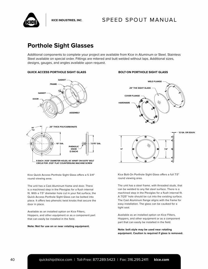
SPEED SPOUT MANUAL
[email protected] | Toll-Free: 877.289.5423 | Fax: 316.295.2411 kice.com40
Porthole Sight GlassesAdditional components to complete your project are available from Kice in Aluminum or Steel. Stainless Steel available on special order. Fittings are mitered and butt welded without laps. Additional sizes, designs, gauges, and angles available upon request.
QUICK ACCESS PORTHOLE SIGHT GLASS
Kice Quick Access Porthole Sight Glass offers a 5 3/4" round viewing area.
The unit has a Cast Aluminum frame and door. There is a machined step in the Plexiglas for a flush internal fit. With a 7.5" diameter hole cut in your flat surface, the Quick Access Porthole Sight Glass can be bolted into place. It offers two phenolic twist knobs that secure the door in place.
Available as an installed option on Kice Filters, Hoppers, and other equipment or as a component part that can easily be installed in the field.
Note: Not for use on or near rotating equipment.
GASKET
FRAME
GASKET
DOOR
ASSEMBLY
60˚ Typ
.25" THICK POLYCARBONATE
10" DIA.PHENOLIC
KNOB(2 EACH)
7.375" DIA.
6 EACH .3125" DIAMETER HOLES, 60˚ APART ON 8.875" BOLT CIRCLE FOR .3125" FLAT COUNTERSUNK MACHINE SCREW
BOLT-ON PORTHOLE SIGHT GLASS
Kice Bolt-On Porthole Sight Glass offers a full 7.5" round viewing area.
The unit has a steel frame, with threaded studs, that can be welded to any flat steel surface. There is a machined step in the Plexiglas for a flush internal fit. A 7.125" hole should be cut into the existing surface. The Cast Aluminum flange aligns with the frame for easy installation. The glass can be caulked for a tight seal.
Available as an installed option on Kice Filters, Hoppers, and other equipment or as a component part that can easily be installed in the field.
Note: bolt style may be used near rotating equipment. Caution is required if glass is removed.
WELD FLANGE
.25" THK SIGHT GLASS
COVER FLANGE
HARDWARE
12 GA. OR EQUIV.
7.5"11"
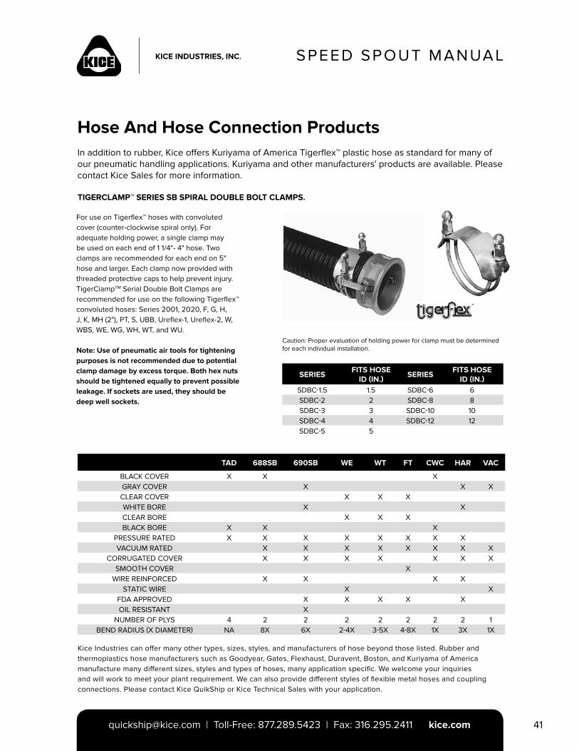
SPEED SPOUT MANUAL
[email protected] | Toll-Free: 877.289.5423 | Fax: 316.295.2411 kice.com 41
Hose And Hose Connection ProductsIn addition to rubber, Kice offers Kuriyama of America Tigerflex™ plastic hose as standard for many of our pneumatic handling applications. Kuriyama and other manufacturers' products are available. Please contact Kice Sales for more information.
TIGERCLAMP™ SERIES SB SPIRAL DOUBLE BOLT CLAMPS.
For use on Tigerflex™ hoses with convoluted cover (counter-clockwise spiral only). For adequate holding power, a single clamp may be used on each end of 1 1/4"- 4" hose. Two clamps are recommended for each end on 5" hose and larger. Each clamp now provided with threaded protective caps to help prevent injury. TigerCiampTM Serial Double Bolt Clamps are recommended for use on the following Tigerflex™ convoluted hoses: Series 2001, 2020, F, G, H, J, K, MH (2"), PT, S, UBB, Ureflex-1, Ureflex-2, W, WBS, WE, WG, WH, WT, and WU.
Note: Use of pneumatic air tools for tightening purposes is not recommended due to potential clamp damage by excess torque. Both hex nuts should be tightened equally to prevent possible leakage. If sockets are used, they should be deep well sockets.
SERIESFITS HOSE
ID (IN.)SERIES
FITS HOSE ID (IN.)
SDBC-1.5 1.5 SDBC-6 6SDBC-2 2 SDBC-8 8SDBC-3 3 SDBC-10 10SDBC-4 4 SDBC-12 12SDBC-5 5
TAD 688SB 690SB WE WT FT CWC HAR VAC
BLACK COVER X X XGRAY COVER X X XCLEAR COVER X X XWHITE BORE X XCLEAR BORE X X XBLACK BORE X X X
PRESSURE RATED X X X X X X X XVACUUM RATED X X X X X X X X
CORRUGATED COVER X X X X X X XSMOOTH COVER X
WIRE REINFORCED X X X XSTATIC WIRE X X
FDA APPROVED X X X X XOIL RESISTANT X
NUMBER OF PLYS 4 2 2 2 2 2 2 2 1BEND RADIUS (X DIAMETER) NA 8X 6X 2-4X 3-5X 4-8X 1X 3X 1X
Kice Industries can offer many other types, sizes, styles, and manufacturers of hose beyond those listed. Rubber and thermoplastics hose manufacturers such as Goodyear, Gates, Flexhaust, Duravent, Boston, and Kuriyama of America manufacture many different sizes, styles and types of hoses, many application specific. We welcome your inquiries and will work to meet your plant requirement. We can also provide different styles of flexible metal hoses and coupling connections. Please contact Kice QuikShip or Kice Technical Sales with your application.
Caution: Proper evaluation of holding power for clamp must be determined for each individual installation.
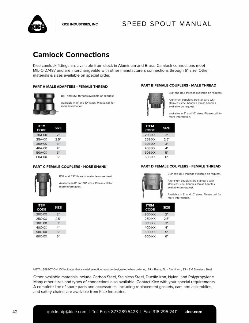
SPEED SPOUT MANUAL
[email protected] | Toll-Free: 877.289.5423 | Fax: 316.295.2411 kice.com42
Camlock ConnectionsKice camlock fittings are available from stock in Aluminum and Brass. Camlock connections meet MIL-C-27487 and are interchangeable with other manufacturers connections through 6" size. Other materials & sizes available on special order.
PART A MALE ADAPTERS - FEMALE THREAD PART B FEMALE COUPLERS - MALE THREAD
PART D FEMALE COUPLERS - FEMALE THREAD
BSP and BST threads available on request.
Available in 8" and 10" sizes. Please call for more information.
ITEMCODE
SIZE
20A-XX 2"25A-XX 2.5"30A-XX 3"40A-XX 4"50A-XX 5"60A-XX 6"
BSP and BST threads available on request.
Aluminum couplers are standard with stainless-steel handles. Brass handles available on request.
Available in 8" and 10" sizes. Please call for more information.
ITEMCODE
SIZE
20D-XX 2"25D-XX 2.5"30D-XX 3"40D-XX 4"50D-XX 5"60D-XX 6"
ITEMCODE
SIZE
20B-XX 2"25B-XX 2.5"30B-XX 3"40B-XX 4"50B-XX 5"60B-XX 6"
BSP and BST threads available on request.
Aluminum couplers are standard with stainless-steel handles. Brass handles available on request.
available in 8" and 10" sizes. Please call for more information.
PART C FEMALE COUPLERS - HOSE SHANK
ITEMCODE
SIZE
20C-XX 2"25C-XX 2.5"30C-XX 3"40C-XX 4"50C-XX 5"60C-XX 6"
BSP and BST threads available on request.
Available in 8" and 10" sizes. Please call for more information.
METAL SELECTION: XX indicates that a metal selection must be designated when ordering: BR = Brass; AL = Aluminum; SS = 316 Stainless Steel
Other available materials include Carbon Steel, Stainless Steel, Ductile Iron, Nylon, and Polypropylene. Many other sizes and types of connections also available. Contact Kice with your special requirements. A complete line of spare parts and accessories, including replacement gaskets, cam arm assemblies, and safety chains, are available from Kice Industries.
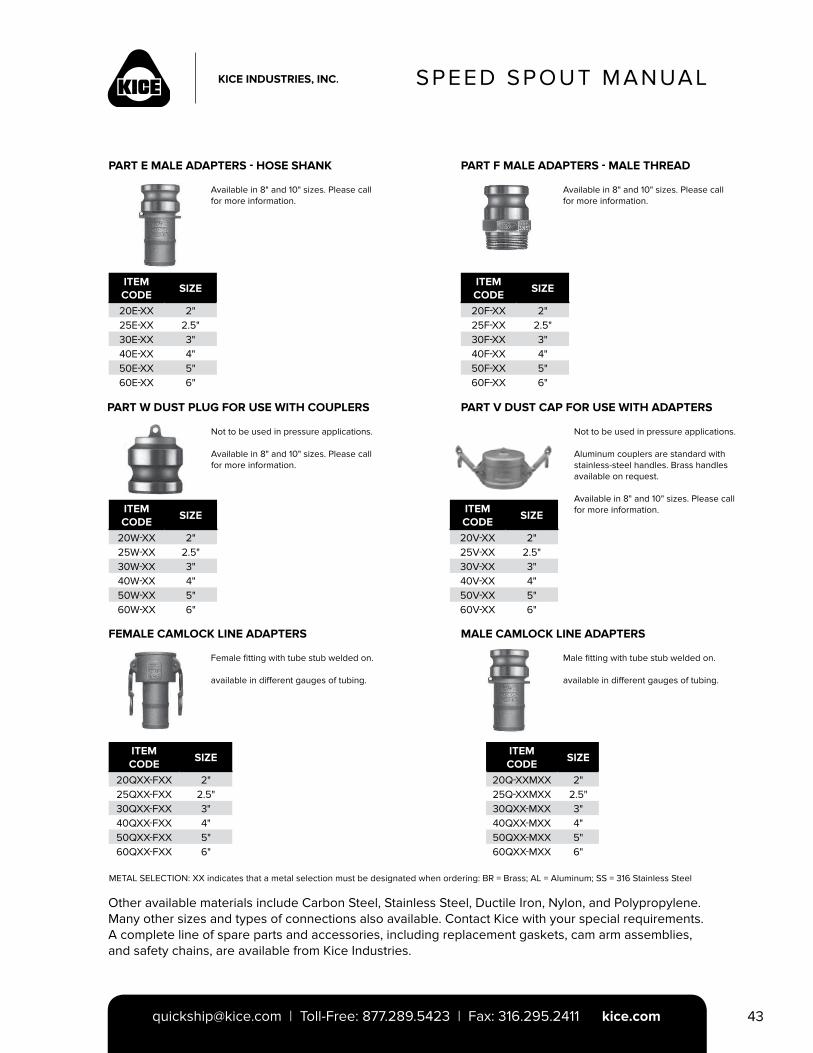
SPEED SPOUT MANUAL
[email protected] | Toll-Free: 877.289.5423 | Fax: 316.295.2411 kice.com 43
PART E MALE ADAPTERS - HOSE SHANK PART F MALE ADAPTERS - MALE THREAD
PART W DUST PLUG FOR USE WITH COUPLERS
ITEMCODE
SIZE
20E-XX 2"25E-XX 2.5"30E-XX 3"40E-XX 4"50E-XX 5"60E-XX 6"
Available in 8" and 10" sizes. Please call for more information.
ITEMCODE
SIZE
20F-XX 2"25F-XX 2.5"30F-XX 3"40F-XX 4"50F-XX 5"60F-XX 6"
Available in 8" and 10" sizes. Please call for more information.
ITEMCODE
SIZE
20W-XX 2"25W-XX 2.5"30W-XX 3"40W-XX 4"50W-XX 5"60W-XX 6"
Not to be used in pressure applications.
Available in 8" and 10" sizes. Please call for more information.
PART V DUST CAP FOR USE WITH ADAPTERS
ITEMCODE
SIZE
20V-XX 2"25V-XX 2.5"30V-XX 3"40V-XX 4"50V-XX 5"60V-XX 6"
Not to be used in pressure applications.
Aluminum couplers are standard with stainless-steel handles. Brass handles available on request.
Available in 8" and 10" sizes. Please call for more information.
METAL SELECTION: XX indicates that a metal selection must be designated when ordering: BR = Brass; AL = Aluminum; SS = 316 Stainless Steel
Other available materials include Carbon Steel, Stainless Steel, Ductile Iron, Nylon, and Polypropylene. Many other sizes and types of connections also available. Contact Kice with your special requirements. A complete line of spare parts and accessories, including replacement gaskets, cam arm assemblies, and safety chains, are available from Kice Industries.
FEMALE CAMLOCK LINE ADAPTERS MALE CAMLOCK LINE ADAPTERS
Female fitting with tube stub welded on.
available in different gauges of tubing.
Male fitting with tube stub welded on.
available in different gauges of tubing.
ITEMCODE
SIZE
20Q-XXMXX 2"25Q-XXMXX 2.5"30QXX-MXX 3"40QXX-MXX 4"50QXX-MXX 5"60QXX-MXX 6"
ITEMCODE
SIZE
20QXX-FXX 2"25QXX-FXX 2.5"30QXX-FXX 3"40QXX-FXX 4"50QXX-FXX 5"60QXX-FXX 6"
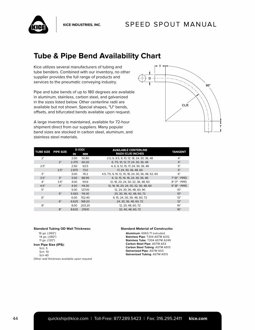
SPEED SPOUT MANUAL
[email protected] | Toll-Free: 877.289.5423 | Fax: 316.295.2411 kice.com44
Tube & Pipe Bend Availability ChartKice utilizes several manufacturers of tubing and tube benders. Combined with our inventory, no other supplier provides the full range of products and services to the pneumatic conveying industry.
Pipe and tube bends of up to 180 degrees are available in aluminum, stainless, carbon steel, and galvanized in the sizes listed below. Other centerline radii are available but not shown. Special shapes, "U" bends, offsets, and bifurcated bends available upon request.
A large inventory is maintained, available for 72-hour shipment direct from our suppliers. Many popular bend sizes are stocked in carbon steel, aluminum, and stainless steel materials.
TUBE SIZE PIPE SIZE D (OD) AVAILABLE CENTERLINE
RADII (CLR) INCHESTANGENT
IN MM2" 2.00 50.80 2.5, 6, 8.5, 9, 10, 12, 18, 24, 30, 36, 48 4"
2" 2.375 60.20 6, 7.5, 10, 12, 17, 24, 30, 36, 48 4"2.5" 2.50 63.5 4, 6, 9, 12, 15, 17, 24, 30, 36, 48 5"
2.5" 2.875 73.0 17, 24, 30, 36, 48, 60 5"3" 3.00 76.2 4.5, 7.5, 9, 10, 12, 15, 18, 24, 30, 36, 48, 52, 60 6"
3.5" 3" 3.50 88.99 6, 12, 15, 16, 18, 24, 30, 36, 48 7" (6" - PIPE)4" 3.5" 4.00 101.6 12, 18, 20, 24, 30, 32, 36, 48, 60 8" (7" - PIPE)
4.5" 4" 4.50 114.30 12, 16, 18, 20, 24, 30, 32, 36, 48, 60 9" (8" - PIPE)5" 5.00 127.00 12, 24, 30, 36, 48, 60, 90 10"
5" 5.563 114.30 20, 30, 36, 42, 48, 60, 72 10"6" 6.00 152.40 9, 15, 24, 30, 36, 48, 60, 72 12"
6" 6.625 168.20 24, 30, 36, 48, 60, 72 12"8" 8.00 203.20 12, 20, 48, 60, 72 16"
8" 8.625 219.10 32, 40, 48, 60, 72 16"
Standard Tubing OD Wall Thickness: 16 ga. (.065") 14 ga. (.083") 11 ga. (.120")
Iron Pipe Size (IPS): Sch. 5 Sch. 10 Sch 40Other wall thickness available upon request
Standard Material of Constructio: Aluminum: 6063-T1 extruded Stainless Pipe: T304 ASTM A312 Stainless Tube: T304 ASTM A249 Carbon Steel Pipe: ASTM A53 Carbon Steel Tubing: ASTM A513 Galvanized Pipe: ASTM A53 Galvanized Tubing: ASTM A513
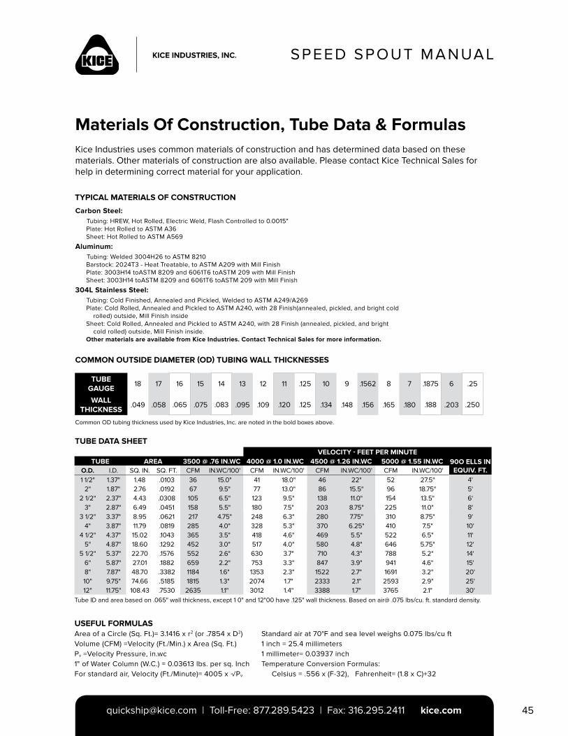
SPEED SPOUT MANUAL
[email protected] | Toll-Free: 877.289.5423 | Fax: 316.295.2411 kice.com 45
Materials Of Construction, Tube Data & FormulasKice Industries uses common materials of construction and has determined data based on these materials. Other materials of construction are also available. Please contact Kice Technical Sales for help in determining correct material for your application.
TYPICAL MATERIALS OF CONSTRUCTION
TUBE GAUGE
18 17 16 15 14 13 12 11 .125 10 9 .1562 8 7 .1875 6 .25
WALL THICKNESS
.049 .058 .065 .075 .083 .095 .109 .120 .125 .134 .148 .156 .165 .180 .188 .203 .250
Carbon Steel: Tubing: HREW, Hot Rolled, Electric Weld, Flash Controlled to 0.0015" Plate: Hot Rolled to ASTM A36 Sheet: Hot Rolled to ASTM A569
Aluminum: Tubing: Welded 3004H26 to ASTM 8210 Barstock: 2024T3 - Heat Treatable, to ASTM A209 with Mill Finish Plate: 3003H14 toASTM 8209 and 6061T6 toASTM 209 with Mill Finish Sheet: 3003H14 toASTM 8209 and 6061T6 toASTM 209 with Mill Finish
304L Stainless Steel: Tubing: Cold Finished, Annealed and Pickled, Welded to ASTM A249/A269 Plate: Cold Rolled, Annealed and Pickled to ASTM A240, with 28 Finish(annealed, pickled, and bright cold rolled) outside, Mill Finish inside Sheet: Cold Rolled, Annealed and Pickled to ASTM A240, with 28 Finish (annealed, pickled, and bright cold rolled) outside, Mill Finish inside. Other materials are available from Kice Industries. Contact Technical Sales for more information.
COMMON OUTSIDE DIAMETER (OD) TUBING WALL THICKNESSES
Common OD tubing thickness used by Kice Industries, Inc. are noted in the bold boxes above.
VELOCITY - FEET PER MINUTETUBE AREA 3500 @ .76 IN.WC 4000 @ 1.0 IN.WC 4500 @ 1.26 IN.WC 5000 @ 1.55 IN.WC 90O ELLS IN
EQUIV. FT.O.D. I.D. SQ. IN. SQ. FT. CFM IN.WC/100' CFM IN.WC/100' CFM IN.WC/100' CFM IN.WC/100'1 1/2" 1.37" 1.48 .0103 36 15.0" 41 18.0" 46 22" 52 27.5" 4'
2" 1.87" 2.76 .0192 67 9.5" 77 13.0" 86 15.5" 96 18.75" 5'2 1/2" 2.37" 4.43 .0308 105 6.5" 123 9.5" 138 11.0" 154 13.5" 6'
3" 2.87" 6.49 .0451 158 5.5" 180 7.5" 203 8.75" 225 11.0" 8'3 1/2" 3.37" 8.95 .0621 217 4.75" 248 6.3" 280 7.75" 310 8.75" 9'
4" 3.87" 11.79 .0819 285 4.0" 328 5.3" 370 6.25" 410 7.5" 10'4 1/2" 4.37" 15.02 .1043 365 3.5" 418 4.6" 469 5.5" 522 6.5" 11'
5" 4.87" 18.60 .1292 452 3.0" 517 4.0" 580 4.8" 646 5.75" 12'5 1/2" 5.37" 22.70 .1576 552 2.6" 630 3.7" 710 4.3" 788 5.2" 14'
6" 5.87" 27.01 .1882 659 2.2" 753 3.3" 847 3.9" 941 4.6" 15'8" 7.87" 48.70 .3382 1184 1.6" 1353 2.3" 1522 2.7" 1691 3.2" 20'10" 9.75" 74.66 .5185 1815 1.3" 2074 1.7" 2333 2.1" 2593 2.9" 25'12" 11.75" 108.43 .7530 2635 1.1" 3012 1.4" 3388 1.7" 3765 2.1" 30'
TUBE DATA SHEET
Tube ID and area based on .065" wall thickness, except 1 0" and 12"00 have .125" wall thickness. Based on air@ .075 lbs/cu. ft. standard density.
USEFUL FORMULASArea of a Circle (Sq. Ft.)= 3.1416 x r2 (or .7854 x D2)Volume (CFM) =Velocity (Ft./Min.) x Area (Sq. Ft.)Pv =Velocity Pressure, in.wc1" of Water Column (W.C.) = 0.03613 lbs. per sq. InchFor standard air, Velocity (Ft./Minute)= 4005 x √Pv
Standard air at 70°F and sea level weighs 0.075 lbs/cu ft1 inch = 25.4 millimeters1 millimeter= 0.03937 inchTemperature Conversion Formulas: Celsius = .556 x (F-32), Fahrenheit= (1.8 x C)+32
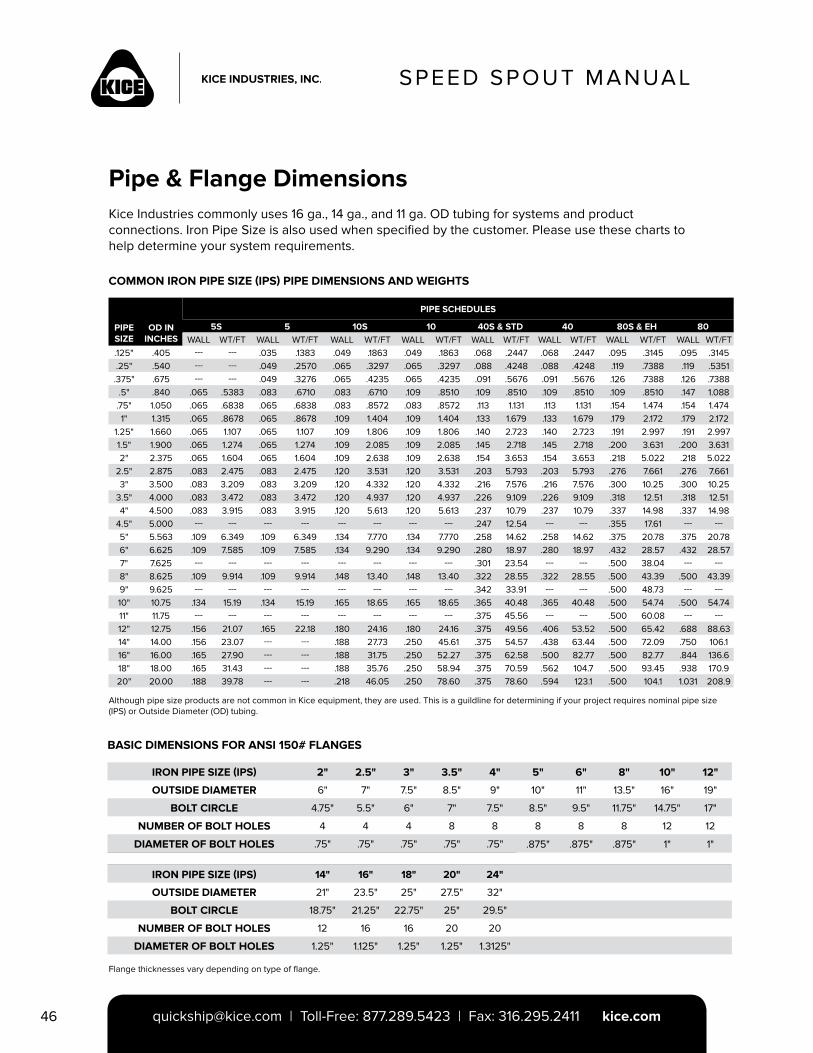
SPEED SPOUT MANUAL
[email protected] | Toll-Free: 877.289.5423 | Fax: 316.295.2411 kice.com46
Pipe & Flange DimensionsKice Industries commonly uses 16 ga., 14 ga., and 11 ga. OD tubing for systems and product connections. Iron Pipe Size is also used when specified by the customer. Please use these charts to help determine your system requirements.
COMMON IRON PIPE SIZE (IPS) PIPE DIMENSIONS AND WEIGHTS
PIPE SCHEDULES
PIPE SIZE
OD IN INCHES
5S 5 10S 10 40S & STD 40 80S & EH 80WALL WT/FT WALL WT/FT WALL WT/FT WALL WT/FT WALL WT/FT WALL WT/FT WALL WT/FT WALL WT/FT
.125" .405 --- --- .035 .1383 .049 .1863 .049 .1863 .068 .2447 .068 .2447 .095 .3145 .095 .3145.25" .540 --- --- .049 .2570 .065 .3297 .065 .3297 .088 .4248 .088 .4248 .119 .7388 .119 .5351.375" .675 --- --- .049 .3276 .065 .4235 .065 .4235 .091 .5676 .091 .5676 .126 .7388 .126 .7388
.5" .840 .065 .5383 .083 .6710 .083 .6710 .109 .8510 .109 .8510 .109 .8510 .109 .8510 .147 1.088.75" 1.050 .065 .6838 .065 .6838 .083 .8572 .083 .8572 .113 1.131 .113 1.131 .154 1.474 .154 1.4741" 1.315 .065 .8678 .065 .8678 .109 1.404 .109 1.404 .133 1.679 .133 1.679 .179 2.172 .179 2.172
1.25" 1.660 .065 1.107 .065 1.107 .109 1.806 .109 1.806 .140 2.723 .140 2.723 .191 2.997 .191 2.9971.5" 1.900 .065 1.274 .065 1.274 .109 2.085 .109 2.085 .145 2.718 .145 2.718 .200 3.631 .200 3.6312" 2.375 .065 1.604 .065 1.604 .109 2.638 .109 2.638 .154 3.653 .154 3.653 .218 5.022 .218 5.022
2.5" 2.875 .083 2.475 .083 2.475 .120 3.531 .120 3.531 .203 5.793 .203 5.793 .276 7.661 .276 7.6613" 3.500 .083 3.209 .083 3.209 .120 4.332 .120 4.332 .216 7.576 .216 7.576 .300 10.25 .300 10.25
3.5" 4.000 .083 3.472 .083 3.472 .120 4.937 .120 4.937 .226 9.109 .226 9.109 .318 12.51 .318 12.514" 4.500 .083 3.915 .083 3.915 .120 5.613 .120 5.613 .237 10.79 .237 10.79 .337 14.98 .337 14.98
4.5" 5.000 --- --- --- --- --- --- --- --- .247 12.54 --- --- .355 17.61 --- ---5" 5.563 .109 6.349 .109 6.349 .134 7.770 .134 7.770 .258 14.62 .258 14.62 .375 20.78 .375 20.786" 6.625 .109 7.585 .109 7.585 .134 9.290 .134 9.290 .280 18.97 .280 18.97 .432 28.57 .432 28.577" 7.625 --- --- --- --- --- --- --- --- .301 23.54 --- --- .500 38.04 --- ---8" 8.625 .109 9.914 .109 9.914 .148 13.40 .148 13.40 .322 28.55 .322 28.55 .500 43.39 .500 43.399" 9.625 --- --- --- --- --- --- --- --- .342 33.91 --- --- .500 48.73 --- ---10" 10.75 .134 15.19 .134 15.19 .165 18.65 .165 18.65 .365 40.48 .365 40.48 .500 54.74 .500 54.7411" 11.75 --- --- --- --- --- --- --- --- .375 45.56 --- --- .500 60.08 --- ---12" 12.75 .156 21.07 .165 22.18 .180 24.16 .180 24.16 .375 49.56 .406 53.52 .500 65.42 .688 88.6314" 14.00 .156 23.07 --- --- .188 27.73 .250 45.61 .375 54.57 .438 63.44 .500 72.09 .750 106.116" 16.00 .165 27.90 --- --- .188 31.75 .250 52.27 .375 62.58 .500 82.77 .500 82.77 .844 136.618" 18.00 .165 31.43 --- --- .188 35.76 .250 58.94 .375 70.59 .562 104.7 .500 93.45 .938 170.920" 20.00 .188 39.78 --- --- .218 46.05 .250 78.60 .375 78.60 .594 123.1 .500 104.1 1.031 208.9
IRON PIPE SIZE (IPS) 2" 2.5" 3" 3.5" 4" 5" 6" 8" 10" 12"
OUTSIDE DIAMETER 6" 7" 7.5" 8.5" 9" 10" 11" 13.5" 16" 19"
BOLT CIRCLE 4.75" 5.5" 6" 7" 7.5" 8.5" 9.5" 11.75" 14.75" 17"
NUMBER OF BOLT HOLES 4 4 4 8 8 8 8 8 12 12
DIAMETER OF BOLT HOLES .75" .75" .75" .75" .75" .875" .875" .875" 1" 1"
IRON PIPE SIZE (IPS) 14" 16" 18" 20" 24"
OUTSIDE DIAMETER 21" 23.5" 25" 27.5" 32"
BOLT CIRCLE 18.75" 21.25" 22.75" 25" 29.5"
NUMBER OF BOLT HOLES 12 16 16 20 20
DIAMETER OF BOLT HOLES 1.25" 1.125" 1.25" 1.25" 1.3125"
Although pipe size products are not common in Kice equipment, they are used. This is a guildline for determining if your project requires nominal pipe size (IPS) or Outside Diameter (OD) tubing.
Flange thicknesses vary depending on type of flange.
BASIC DIMENSIONS FOR ANSI 150# FLANGES
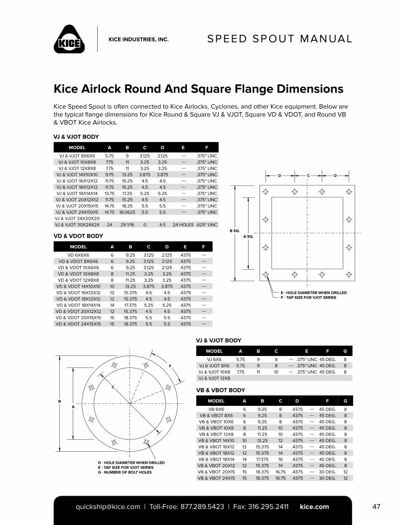
SPEED SPOUT MANUAL
[email protected] | Toll-Free: 877.289.5423 | Fax: 316.295.2411 kice.com 47
Kice Airlock Round And Square Flange DimensionsKice Speed Spout is often connected to Kice Airlocks, Cyclones, and other Kice equipment. Below are the typical flange dimensions for Kice Round & Square VJ & VJOT, Square VD & VDOT, and Round VB & VBOT Kice Airlocks.
VJ & VJOT BODY
MODEL A B C D E F
VJ & VJOT 8X6X6 5.75 9 3.125 2.125 --- .375" UNCVJ & VJOT 10X8X8 7.75 11 3.25 3.25 --- .375" UNCVJ & VJOT 12X8X8 7.75 11 3.25 3.25 --- .375" UNC
VJ & VJOT 14X10X10 9.75 13.25 3.875 3.875 --- .375" UNCVJ & VJOT 16X12X12 11.75 15.25 4.5 4.5 --- .375" UNCVJ & VJOT 18X12X12 11.75 15.25 4.5 4.5 --- .375" UNCVJ & VJOT 18X14X14 13.75 17.25 5.25 5.25 --- .375" UNCVJ & VJOT 20X12X12 11.75 15.25 4.5 4.5 --- .375" UNCVJ & VJOT 20X15X15 14.75 18.25 5.5 5.5 --- .375" UNCVJ & VJOT 24X15X15 14.75 18.0625 5.5 5.5 --- .375" UNC
VJ & VJOT 24X20X20VJ & VJOT 30X24X24 24 29 1/16 0 4.5 24 HOLES .625" UNC
MODEL A B C D E F
VD 6X6X6 6 9.25 3.125 2.125 .4375 ---VD & VDOT 8X6X6 6 9.25 3.125 2.125 .4375 ---VD & VDOT 10X6X6 6 9.25 3.125 2.125 .4375 ---VD & VDOT 10X8X8 8 11.25 3.25 3.25 .4375 ---VD & VDOT 12X8X8 8 11.25 3.25 3.25 .4375 ---
VD & VDOT 14X10X10 10 13.25 3.875 3.875 .4375 ---VD & VDOT 16X12X12 12 15.375 4.5 4.5 .4375 ---VD & VDOT 18X12X12 12 15.375 4.5 4.5 .4375 ---VD & VDOT 18X14X14 14 17.375 5.25 5.25 .4375 ---VD & VDOT 20X12X12 12 15.375 4.5 4.5 .4375 ---VD & VDOT 20X15X15 15 18.375 5.5 5.5 .4375 ---VD & VDOT 24X15X15 15 18.375 5.5 5.5 .4375 ---
VD & VDOT BODY
MODEL A B C E F G
VJ 6X6 5.75 9 8 --- .375" UNC 45 DEG. 8VJ & VJOT 8X6 5.75 9 8 --- .375" UNC 45 DEG. 8VJ & VJOT 10X8 7.75 11 10 --- .375" UNC 45 DEG. 8VJ & VJOT 12X8
MODEL A B C D F G
VB 6X6 6 9.25 8 .4375 --- 45 DEG. 8VB & VBOT 8X6 6 9.25 8 .4375 --- 45 DEG. 8VB & VBOT 10X6 6 9.25 8 .4375 --- 45 DEG. 8VB & VBOT 10X8 8 11.25 10 .4375 --- 45 DEG. 8VB & VBOT 12X8 8 11.25 10 .4375 --- 45 DEG. 8VB & VBOT 14X10 10 13.25 12 .4375 --- 45 DEG. 8VB & VBOT 16X12 12 15.375 14 .4375 --- 45 DEG. 8VB & VBOT 18X12 12 15.375 14 .4375 --- 45 DEG. 8VB & VBOT 18X14 14 17.375 16 .4375 --- 45 DEG. 8VB & VBOT 20X12 12 15.375 14 .4375 --- 45 DEG. 8VB & VBOT 20X15 15 18.375 16.75 .4375 --- 30 DEG. 12VB & VBOT 24X15 15 18.375 16.75 .4375 --- 30 DEG. 12
VJ & VJOT BODY
VB & VBOT BODY
E - HOLE DIAMETER WHEN DRILLEDF - TAP SIZE FOR VJOT SERIES
B SQ.A SQ.
D C D
BA
C
F
D - HOLE DIAMETER WHEN DRILLEDE - TAP SIZE FOR VJOT SERIESG - NUMBER OF BOLT HOLES

PDB-3-8/12© 2013 Kice Industries, Inc.
5500 N. Mill Heights Dr.Wichita, KS 67219-2358(P) 316.744.7151(F) [email protected]
kice.com