split mandrel coldworking – holes (aluminum) · split mandrel coldworking – holes (aluminum)...
TRANSCRIPT
14900 Whitman Ave. N Tel: (206) 365-7513Seat tle, Washington 98133 Fax: (206) 365-7483
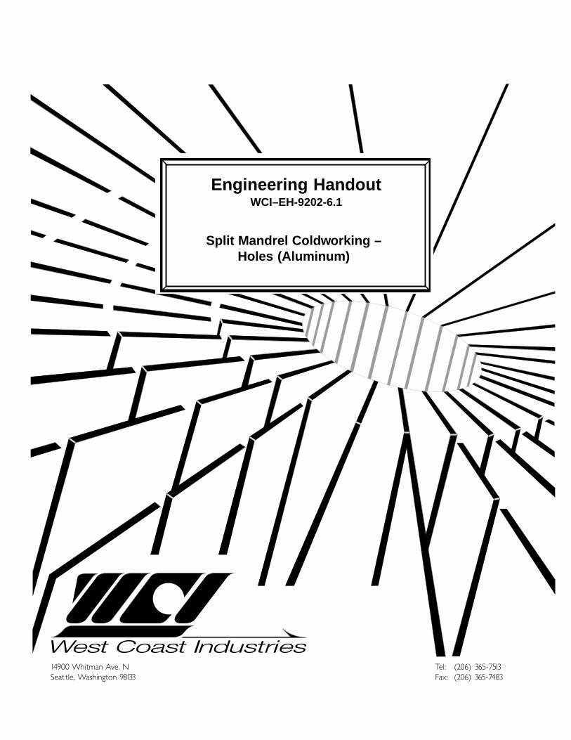
Engineering HandoutWCI–EH-9202-6.1
Split Mandrel Coldworking –Holes (Aluminum)
Table of Contents
1 Scope
2 Definitions
3 Tooling Descriptions
4 Split Mandrel Coldworking ofFastener Holes—Procedures
5 CMS Process Tooling Tables
6 CMX Process Tooling Table
7 Countersink Extension Nosecap
8 Safety
9 Quality Assurance/Control
Split Mandrel Coldworking –Holes (Aluminum)
May 5, 1997
NoticeInformation used in this document is periodically updated. Please contact West Coast Industries for the
latest revision. This document is unpublished and was created on the date listed above. All rights reserved underthe copyright laws by West Coast Industries.
West Coast Industries' proprietary rights are included in the information disclosed herein. Recipient, byaccepting this document, agrees that neither this document, nor the information disclosed herein, nor any partthereof, shall be reproduced or transferred to other documents, or used or disclosed to others, for manufacturingor for any other purpose except as specifically authorized in advance and in writing by West Coast Industries.
14900 Whitman Ave. N Tel: (206) 365-7513Seattle, Washington 98133 Fax: (206) 365-7483
Engineering HandoutWCI–EH-9202-6.1
The information contained herein is subject to the data rights legend on the title page
Split Mandrel Coldworking Engineering Handout – WCI-9202-6.1 1
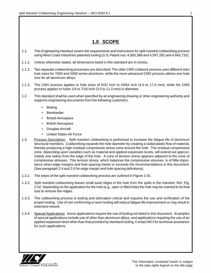
1.0 SCOPE
1.1. This Engineering Handout covers the requirements and instructions for split mandrel coldworking processusing West Coast Industries patented tooling (U.S. Patent nos. 4,583,388 and 4,597,282 and 4,665,732).
1.1.1. Unless otherwise stated, all dimensions listed in this standard are in inches.
1.1.2. Two separate coldworking processes are described The older CMS coldwork process uses different starthole sizes for 7000 and 2000 series aluminum, while the more advanced CMX process utilizes one holesize for all aluminum alloys.
1.1.3. The CMX process applies to hole sizes of 5/32 inch to 43/64 inch (4.0 to 17.0 mm), while the CMSprocess applies to holes 1/4 to 7/16 inch (3.5 to 11.0 mm) in diameter.
1.2. This standard shall be used when specified by an engineering drawing or other engineering authority andsupports engineering documents from the following customers:
• Boeing
• Bombardier
• Bristol Aerospace
• British Aerospace
• Douglas Aircraft
• United States Air Force
1.3. Process Description: Split mandrel coldworking is performed to increase the fatigue life of aluminumstructural members. Coldworking expands the hole diameter by creating a radial plastic flow of material,thereby producing a high residual compressive stress zone around the hole. The residual compressivezone, depending upon variables such as material and applied expansion levels, will extend out approxi-mately one radius from the edge of the hole. A zone of tension stress appears adjacent to the zone ofcompressive stresses. This tension stress, which balances the compressive stresses, is of little impor-tance when edge margins and hole spacing meets or exceeds the recommendations in this document.(See paragraph 2.4 and 2.6 for edge margin and hole spacing definitions).
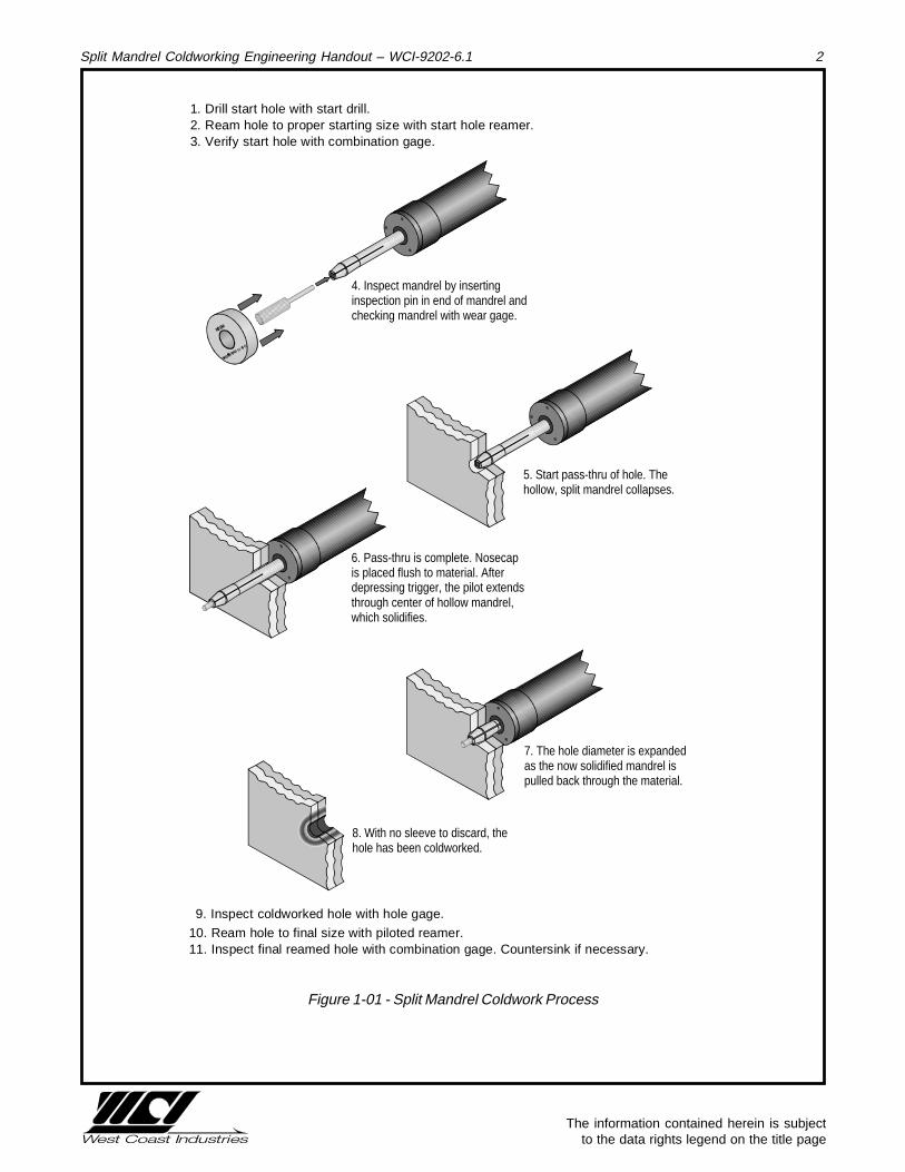
1.3.1. The steps of the split mandrel coldworking process are outlined in Figure 1-01.
1.3.2. Split mandrel coldworking leaves small axial ridges in the hole from the splits in the mandrel. Ref. Fig.2-02. Depending on the application for the hole (e.g., open or filled hole) the hole may be reamed to its finalsize to remove the ridges.
1.3.3. The coldworking process is tooling and lubrication critical and requires the use and verification of theproper tooling. Use of non conforming or worn tooling will reduce fatigue life improvement or may result inextensive rework.
1.3.4. Special Applications Some applications require the use of tooling not listed in this document. Examplesof special applications include use of other than aluminum alloys, and applications requiring the use of anapplied expansion level other than that provided by standard tooling. Contact WCI for technical assistancefor such applications.
The information contained herein is subject to the data rights legend on the title page
Split Mandrel Coldworking Engineering Handout – WCI-9202-6.1 2
������������������������
������������������������
��������������������
��������������������
��������������������
������������������������
9. Inspect coldworked hole with hole gage.
10. Ream hole to final size with piloted reamer.11. Inspect final reamed hole with combination gage. Countersink if necessary.
5. Start pass-thru of hole. The hollow, split mandrel collapses.
6. Pass-thru is complete. Nosecap is placed flush to material. After depressing trigger, the pilot extends through center of hollow mandrel, which solidifies.
7. The hole diameter is expanded as the now solidified mandrel is pulled back through the material.
8. With no sleeve to discard, the hole has been coldworked.
������������������������������
������������������������
����
4. Inspect mandrel by inserting inspection pin in end of mandrel and checking mandrel with wear gage.
1. Drill start hole with start drill.2. Ream hole to proper starting size with start hole reamer.3. Verify start hole with combination gage.
Figure 1-01 - Split Mandrel Coldwork Process
The information contained herein is subject to the data rights legend on the title page
Split Mandrel Coldworking Engineering Handout – WCI-9202-6.1 3
2.0 DEFINITIONS
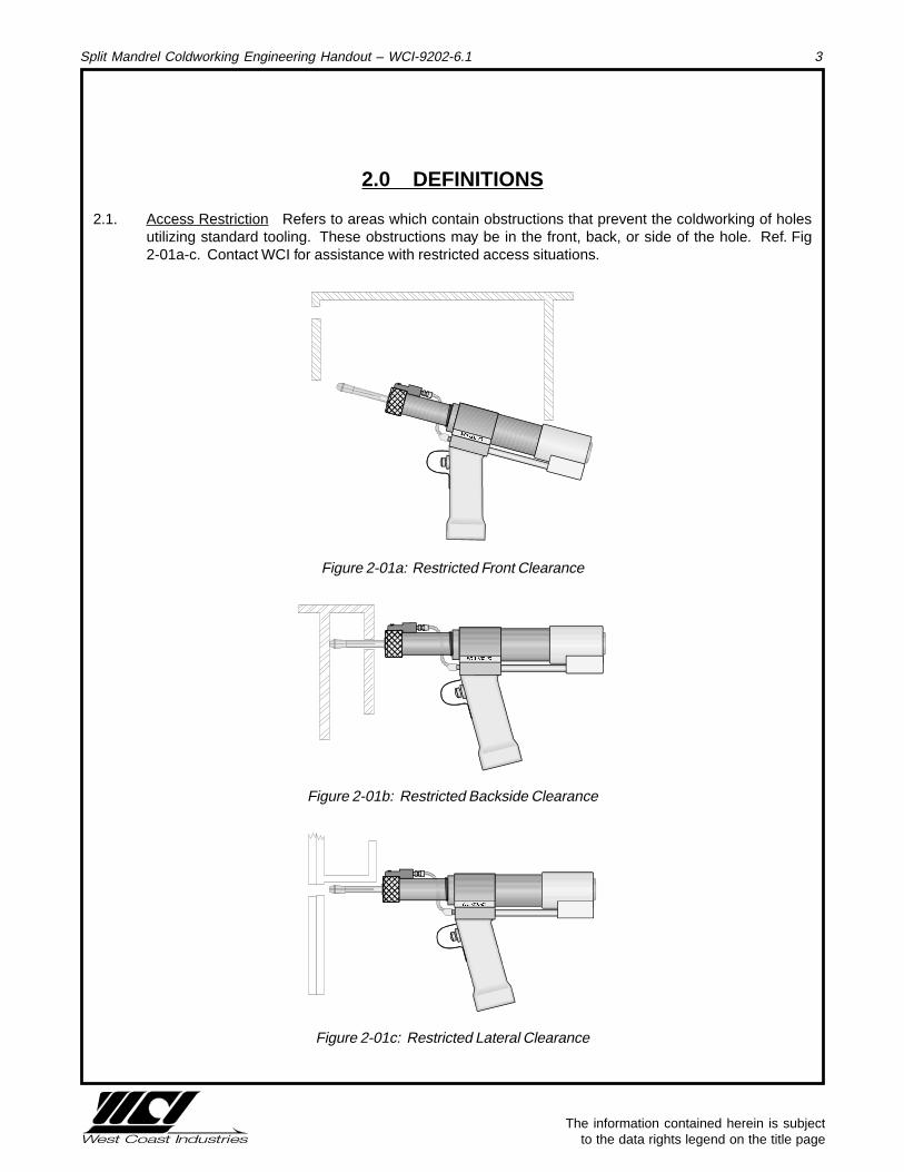
2.1. Access Restriction Refers to areas which contain obstructions that prevent the coldworking of holesutilizing standard tooling. These obstructions may be in the front, back, or side of the hole. Ref. Fig2-01a-c. Contact WCI for assistance with restricted access situations.
�����
Figure 2-01a: Restricted Front Clearance
������
Figure 2-01b: Restricted Backside Clearance
�����
Figure 2-01c: Restricted Lateral Clearance

The information contained herein is subject to the data rights legend on the title page
Split Mandrel Coldworking Engineering Handout – WCI-9202-6.1 4
2.2. Applied Expansion (EA) The maximum amount of expansion a hole experiences during coldworking.Applied Expansion is generally expressed as a percentage ratio between the mandrel major diameter andthe start hole diameter.
%EA = [(Mmandrel major diameter / dstart hole diameter) - 1] x 100
2.3. Axial Ridges Formed by the gaps in the split mandrel during coldworking, the axial ridges (or keys) arespaced 90 degrees apart, and are an indicator of coldworking. (Ref. Fig. 2-02).
Axial Ridges
Figure 2-02 - Axial Ridges
2.4. Edge-Margin Edge margin (e/D) is the ratio between a) the distance from the centerline of the hole to theedge of the part, and b) the final hole diameter. Reworking of fastener holes tends to reduce the edgemargin. Fatigue testing has shown that edge margins of 1.75 or greater are preferred. Use of an interfer-ence fit fastener is recommended for edge margins between 1.25 and 1.75. Ref. Fig. 2-03.
edge margin = e/D where
e = distance from edge of part to center of hole.D = final hole diameter.
Figure 2-03: Edge Margin

The information contained herein is subject to the data rights legend on the title page
Split Mandrel Coldworking Engineering Handout – WCI-9202-6.1 5
2.5. Fatigue - The phenomenon leading to fracture under repeated or fluctuating stresses having a maximumvalue less than the ultimate tensile strength of the material. Fatigue fractures are progressive, beginningas minute cracks that grow under the action of the fluctuating stress.
2.6. Hole Spacing Requirements Hole spacing is determined by dividing the distance between the centerlinesof adjacent holes by the largest final hole diameter. WCI recommends a hole spacing of 3 or greater. Forhole spacing less than 3, refer to engineering procedures or contact WCI for assistance. Ref. Fig. 2-04.
≥3D
D
D=Final Hole Diameter
Figure 2-04: Hole Spacing
2.7. Material Stackup The combined thickness of a structure through which a hole is located or the totallength of a bore. Material stackup is important when determining the correct tooling required for a task(e.g., mandrel and puller stroke length). A stackup of material shall have complete faying surface contactduring start hole preparation, coldworking, and final reaming. See paragraph 3.2 Backup Blocks.
2.8. Pull Force The amount of force required to pull a mandrel through a particular material stackup. Pull forceis dependent upon the mandrel to hole interference, material stackup, mandrel taper, lubrication, andmaterial properties.
2.9. Retained Expansion (ER) The resulting increase in hole diameter after coldworking, expressed as apercentage of the applied expansion. This value is variable and proportional to the yield strength of thematerial being coldworked. Generally, greater life improvement is observed with higher retained expansionvalues.
%ER = (Dpost Cw hole - dstart hole diameter)
(Mmandrel Major Diameter - dstart hole diameter)
2.10. Satellite Holes Satellite holes are small holes located around the circumference of a larger hole. Ref. Fig.2-05. WCI recommends that satellite holes should be filled with a steel pin prior to coldworking the largerhole. The purpose of these pins is to prevent the possible collapse of these holes while coldworking thelarger hole. Satellite holes are considered a special application and are not included in this processspecification. Contact WCI for coldworking procedure for this special application.

The information contained herein is subject to the data rights legend on the title page
Split Mandrel Coldworking Engineering Handout – WCI-9202-6.1 6
Figure 2-05: Satellite Holes
2.11. Standard Tool Diameter Number (STDN) The tool code used to identify specific size tooling (e.g. A STDNof 6-0 refers to a 3/16 inch (5 mm) nominal diameter.
2.12. Start Hole Diameter The diameter of the hole prior to coldworking as stated in the process specification.The hole must be measured throughout its length for diameter and roundness. Holes not meeting thedimensional specifications stated in the applicable engineering table, will not provide the desired fatigueenhancement. Holes out of round may be coldworked if the measured minimum and maximum diametersare within specifications as stated in the applicable engineering table. Refer to Paragraph 4.4.
2.13. Stroke The length of movement a mandrel will undergo during the coldworking operation. Mandrels, pilots,and hydraulic puller units are configured for particular stroke lengths.
The information contained herein is subject to the data rights legend on the title page
Split Mandrel Coldworking Engineering Handout – WCI-9202-6.1 7
3.0 TOOLING DESCRIPTION
3.1. Automatic Mandrel Lubricator Automatically supplies lubricant to the split mandrel before coldworking.The lubricator is attached to the powerpak and is connected to the nosecap via a hose assembly. Theamount of lubrication may be adjusted for a variety of coldwork applications.
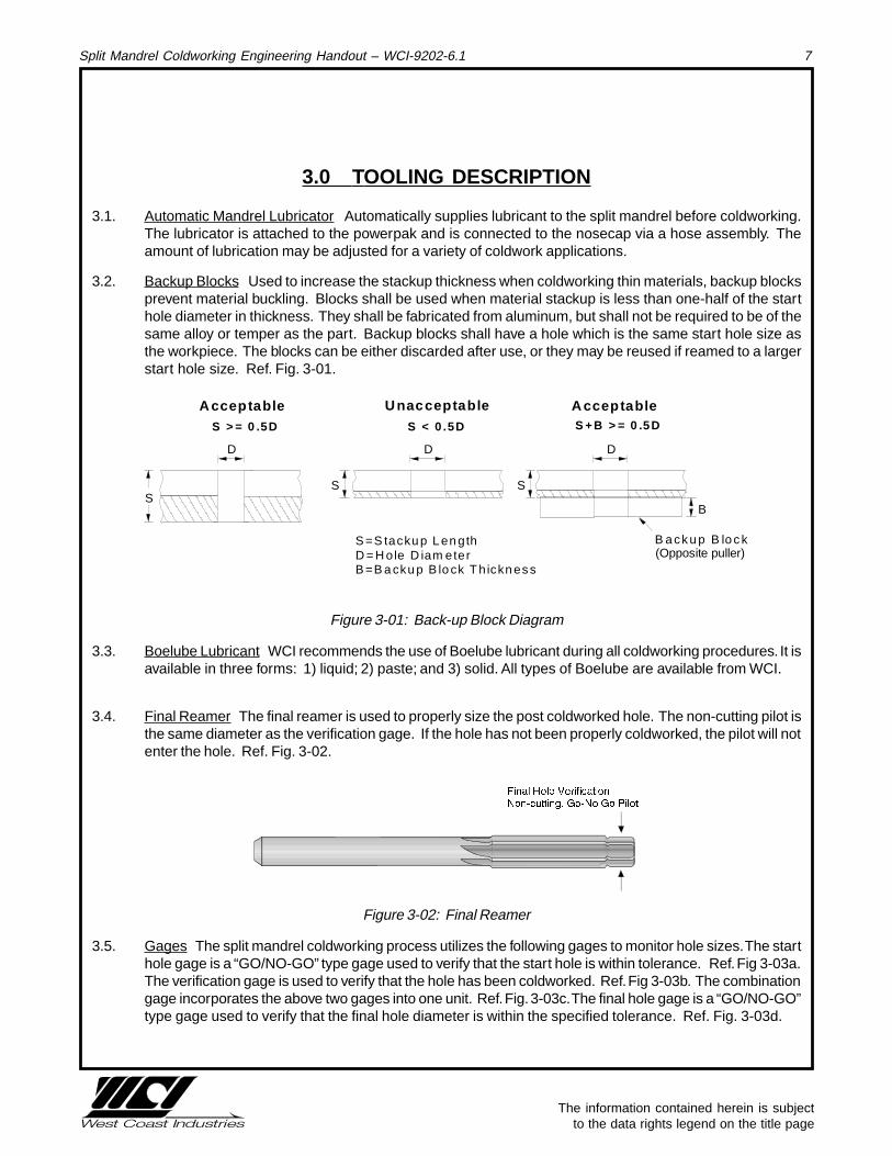
3.2. Backup Blocks Used to increase the stackup thickness when coldworking thin materials, backup blocksprevent material buckling. Blocks shall be used when material stackup is less than one-half of the starthole diameter in thickness. They shall be fabricated from aluminum, but shall not be required to be of thesame alloy or temper as the part. Backup blocks shall have a hole which is the same start hole size asthe workpiece. The blocks can be either discarded after use, or they may be reused if reamed to a largerstart hole size. Ref. Fig. 3-01.
SS
S
B
D D D
S =S tacku p L en gthD = H ole D iam eterB =B a cku p B lo ck T h ickn es s
B a ck u p B lo c k
������
������
������
������
������
A cceptable U nacceptable A cceptable
������
���������
���
S > = 0 .5D S < 0 .5D S +B > = 0 .5D
(Opposite puller)
Figure 3-01: Back-up Block Diagram
3.3. Boelube Lubricant WCI recommends the use of Boelube lubricant during all coldworking procedures. It isavailable in three forms: 1) liquid; 2) paste; and 3) solid. All types of Boelube are available from WCI.
3.4. Final Reamer The final reamer is used to properly size the post coldworked hole. The non-cutting pilot isthe same diameter as the verification gage. If the hole has not been properly coldworked, the pilot will notenter the hole. Ref. Fig. 3-02.
Figure 3-02: Final Reamer
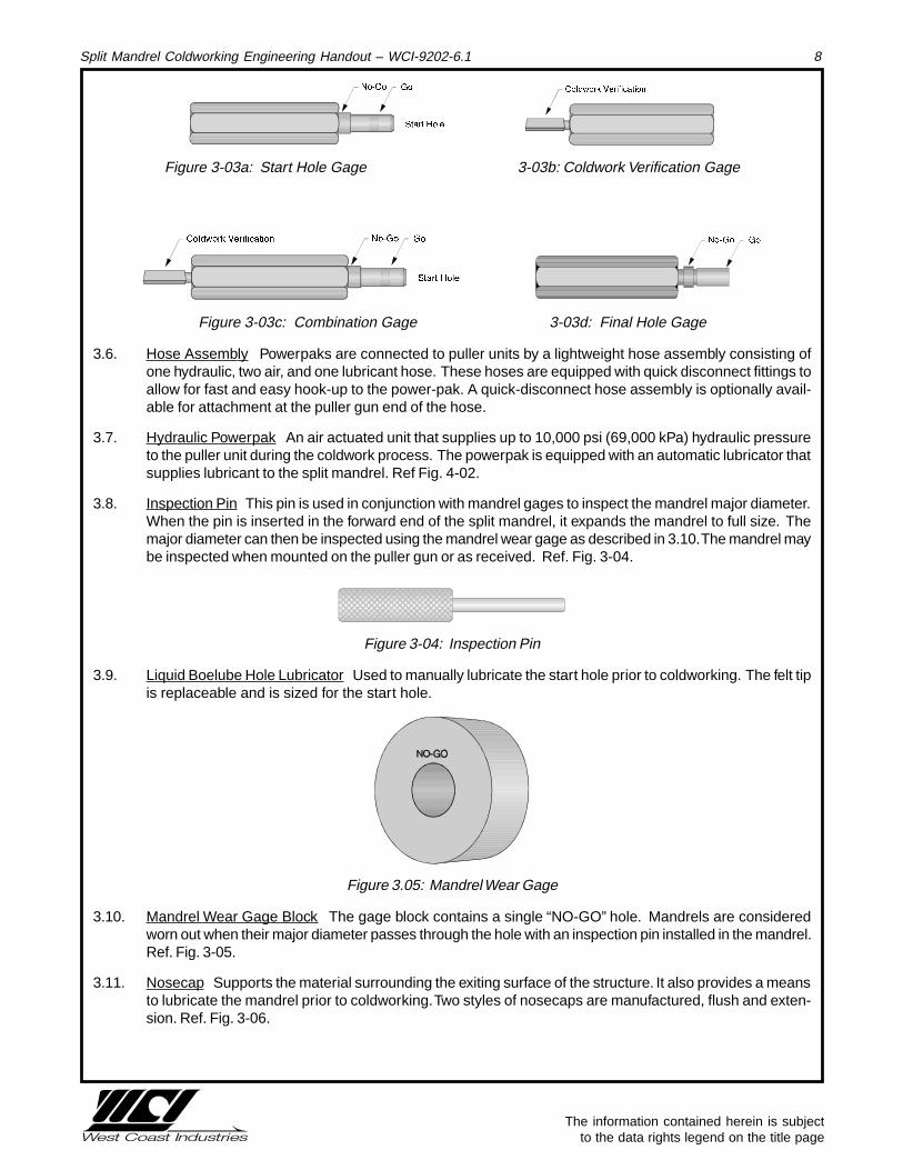
3.5. Gages The split mandrel coldworking process utilizes the following gages to monitor hole sizes. The starthole gage is a “GO/NO-GO” type gage used to verify that the start hole is within tolerance. Ref. Fig 3-03a.The verification gage is used to verify that the hole has been coldworked. Ref. Fig 3-03b. The combinationgage incorporates the above two gages into one unit. Ref. Fig. 3-03c. The final hole gage is a “GO/NO-GO”type gage used to verify that the final hole diameter is within the specified tolerance. Ref. Fig. 3-03d.
The information contained herein is subject to the data rights legend on the title page
Split Mandrel Coldworking Engineering Handout – WCI-9202-6.1 8
Figure 3-03a: Start Hole Gage 3-03b: Coldwork Verification Gage
Figure 3-03c: Combination Gage 3-03d: Final Hole Gage
3.6. Hose Assembly Powerpaks are connected to puller units by a lightweight hose assembly consisting ofone hydraulic, two air, and one lubricant hose. These hoses are equipped with quick disconnect fittings toallow for fast and easy hook-up to the power-pak. A quick-disconnect hose assembly is optionally avail-able for attachment at the puller gun end of the hose.
3.7. Hydraulic Powerpak An air actuated unit that supplies up to 10,000 psi (69,000 kPa) hydraulic pressureto the puller unit during the coldwork process. The powerpak is equipped with an automatic lubricator thatsupplies lubricant to the split mandrel. Ref Fig. 4-02.
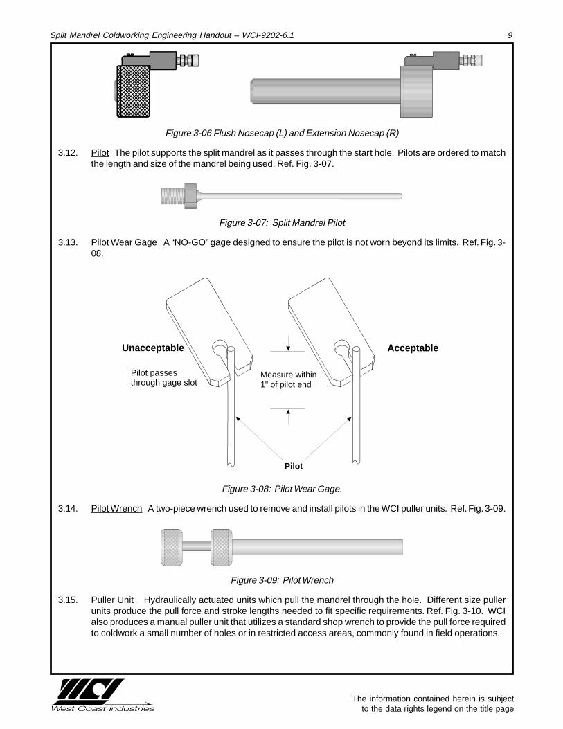
3.8. Inspection Pin This pin is used in conjunction with mandrel gages to inspect the mandrel major diameter.When the pin is inserted in the forward end of the split mandrel, it expands the mandrel to full size. Themajor diameter can then be inspected using the mandrel wear gage as described in 3.10. The mandrel maybe inspected when mounted on the puller gun or as received. Ref. Fig. 3-04.
����������
Figure 3-04: Inspection Pin
3.9. Liquid Boelube Hole Lubricator Used to manually lubricate the start hole prior to coldworking. The felt tipis replaceable and is sized for the start hole.
Figure 3.05: Mandrel Wear Gage
3.10. Mandrel Wear Gage Block The gage block contains a single “NO-GO” hole. Mandrels are consideredworn out when their major diameter passes through the hole with an inspection pin installed in the mandrel.Ref. Fig. 3-05.
3.11. Nosecap Supports the material surrounding the exiting surface of the structure. It also provides a meansto lubricate the mandrel prior to coldworking. Two styles of nosecaps are manufactured, flush and exten-sion. Ref. Fig. 3-06.
The information contained herein is subject to the data rights legend on the title page
Split Mandrel Coldworking Engineering Handout – WCI-9202-6.1 9
������������ ��
��
����
Figure 3-06 Flush Nosecap (L) and Extension Nosecap (R)
3.12. Pilot The pilot supports the split mandrel as it passes through the start hole. Pilots are ordered to matchthe length and size of the mandrel being used. Ref. Fig. 3-07.
Figure 3-07: Split Mandrel Pilot
3.13. Pilot Wear Gage A “NO-GO” gage designed to ensure the pilot is not worn beyond its limits. Ref. Fig. 3-08.
Measure within 1" of pilot end
AcceptableUnacceptable
Pilot
Pilot passes through gage slot
Figure 3-08: Pilot Wear Gage.
3.14. Pilot Wrench A two-piece wrench used to remove and install pilots in the WCI puller units. Ref. Fig. 3-09.
���
������
Figure 3-09: Pilot Wrench
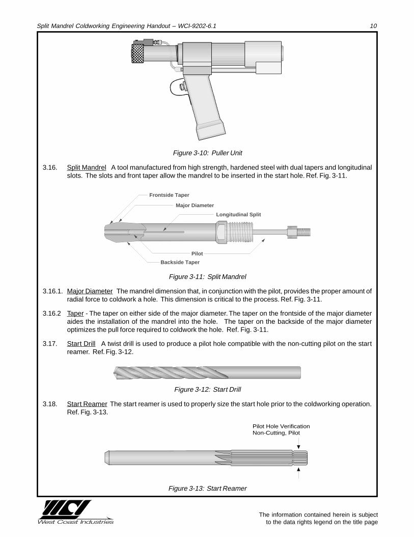
3.15. Puller Unit Hydraulically actuated units which pull the mandrel through the hole. Different size pullerunits produce the pull force and stroke lengths needed to fit specific requirements. Ref. Fig. 3-10. WCIalso produces a manual puller unit that utilizes a standard shop wrench to provide the pull force requiredto coldwork a small number of holes or in restricted access areas, commonly found in field operations.
The information contained herein is subject to the data rights legend on the title page
Split Mandrel Coldworking Engineering Handout – WCI-9202-6.1 10
������
Figure 3-10: Puller Unit
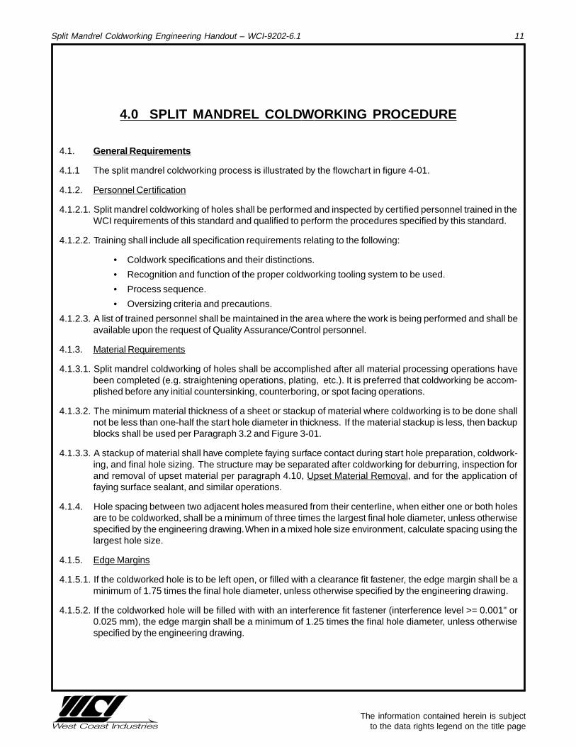
3.16. Split Mandrel A tool manufactured from high strength, hardened steel with dual tapers and longitudinalslots. The slots and front taper allow the mandrel to be inserted in the start hole. Ref. Fig. 3-11.
������������������������������
Pilot
Major Diameter
Frontside Taper
Backside Taper
Longitudinal Split
Figure 3-11: Split Mandrel
3.16.1. Major Diameter The mandrel dimension that, in conjunction with the pilot, provides the proper amount ofradial force to coldwork a hole. This dimension is critical to the process. Ref. Fig. 3-11.
3.16.2 Taper - The taper on either side of the major diameter. The taper on the frontside of the major diameteraides the installation of the mandrel into the hole. The taper on the backside of the major diameteroptimizes the pull force required to coldwork the hole. Ref. Fig. 3-11.
3.17. Start Drill A twist drill is used to produce a pilot hole compatible with the non-cutting pilot on the startreamer. Ref. Fig. 3-12.
Figure 3-12: Start Drill
3.18. Start Reamer The start reamer is used to properly size the start hole prior to the coldworking operation.Ref. Fig. 3-13.
Pilot Hole VerificationNon-Cutting, Pilot
Figure 3-13: Start Reamer
The information contained herein is subject to the data rights legend on the title page
Split Mandrel Coldworking Engineering Handout – WCI-9202-6.1 11
4.0 SPLIT MANDREL COLD WORKING PROCEDURE
4.1. General Requirements
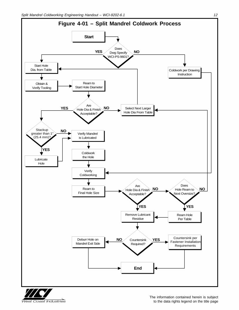
4.1.1 The split mandrel coldworking process is illustrated by the flowchart in figure 4-01.
4.1.2. Personnel Certification
4.1.2.1. Split mandrel coldworking of holes shall be performed and inspected by certified personnel trained in theWCI requirements of this standard and qualified to perform the procedures specified by this standard.
4.1.2.2. Training shall include all specification requirements relating to the following:
• Coldwork specifications and their distinctions.
• Recognition and function of the proper coldworking tooling system to be used.
• Process sequence.
• Oversizing criteria and precautions.
4.1.2.3. A list of trained personnel shall be maintained in the area where the work is being performed and shall beavailable upon the request of Quality Assurance/Control personnel.
4.1.3. Material Requirements
4.1.3.1. Split mandrel coldworking of holes shall be accomplished after all material processing operations havebeen completed (e.g. straightening operations, plating, etc.). It is preferred that coldworking be accom-plished before any initial countersinking, counterboring, or spot facing operations.
4.1.3.2. The minimum material thickness of a sheet or stackup of material where coldworking is to be done shallnot be less than one-half the start hole diameter in thickness. If the material stackup is less, then backupblocks shall be used per Paragraph 3.2 and Figure 3-01.
4.1.3.3. A stackup of material shall have complete faying surface contact during start hole preparation, coldwork-ing, and final hole sizing. The structure may be separated after coldworking for deburring, inspection forand removal of upset material per paragraph 4.10, Upset Material Removal, and for the application offaying surface sealant, and similar operations.
4.1.4. Hole spacing between two adjacent holes measured from their centerline, when either one or both holesare to be coldworked, shall be a minimum of three times the largest final hole diameter, unless otherwisespecified by the engineering drawing. When in a mixed hole size environment, calculate spacing using thelargest hole size.
4.1.5. Edge Margins
4.1.5.1. If the coldworked hole is to be left open, or filled with a clearance fit fastener, the edge margin shall be aminimum of 1.75 times the final hole diameter, unless otherwise specified by the engineering drawing.
4.1.5.2. If the coldworked hole will be filled with with an interference fit fastener (interference level >= 0.001" or0.025 mm), the edge margin shall be a minimum of 1.25 times the final hole diameter, unless otherwisespecified by the engineering drawing.
The information contained herein is subject to the data rights legend on the title page
Split Mandrel Coldworking Engineering Handout – WCI-9202-6.1 12
Figure 4-01 – Split Mandrel Coldwork Process
LubricateHole
Coldwork per Drawing Instruction
AreHole Dia & Finish
Acceptable?
End
Remove LubricantResidue
Countersink perFastener Installation
Requirements
Deburr Hole onMandrel Exit Side
Ream toFinal Hole Size
Verify Mandrelis Lubricated
Select Next LargerHole Dia From Table
Ream toStart Hole Diameter
VerifyColdworking
Coldwork the Hole
CountersinkRequired?
Obtain &Verify Tooling
Start HoleDia. from Table
YES NO
NOYES
NO
YES
YESNO
YES
NO
Ream HolePer Table
AreHole Dia & Finish
Acceptable?
Start
DoesDwg Specify
WCI-PS-9601?
YES
Stackup greater than 1"
(25.4 mm)?
NO
DoesHole Ream to
Next Oversize?
The information contained herein is subject to the data rights legend on the title page
Split Mandrel Coldworking Engineering Handout – WCI-9202-6.1 13
4.1.6. Tool Requirements
4.1.6.1. Mandrels, nosepieces, puller units and adapters, hole check gages, and reamers are precision tools andshall be handled and stored as such.
4.1.6.2. Mandrels, pilots, and gages shall be visually examined by the operator before each use to verify that theyare free from nicks, burrs, metal buildup, or other damage which may cause, or prevent detection ofdefects in the holes.
4.2. Setup Procedure
4.2.1. Sample Specimens The coldworking equipment and attachments used to coldwork holes shall be checkedto ensure that they produce satisfactory coldworked holes in setup specimens simulating production partsprior to coldworking in the following instances:
• When a new part is to be coldworked.
• Prior to beginning each fabrication lot.
4.2.2. Sample specimens shall be produced that comply with the requirements of this document prior to cold-working any production parts using the equipment being checked.
4.3. Tool Selection
4.3.1. Determine the final hole diameter as indicated by engineering documents.
4.3.2. Using the required final hole size, review Tables 5-01 (for the CMS process) or 6-01 (for the CMX process)to determine the applicable standard tool diameter number (STDN). The tool code shall be used to selectthe appropriate coldwork tooling (puller units, mandrels, pilots, nosecaps, drills, and reamers).
4.3.3. Capital Tooling
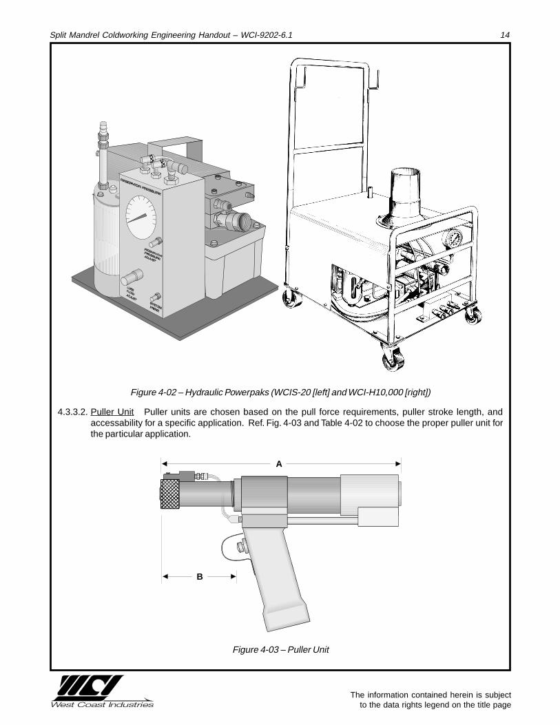
4.3.3.1. Hydraulic Powerpaks WCI manufacturers two powerpaks fitted with automatic lubricators for the splitmandrel process, the WCIS-20, and the WCI-H10,000 (ref figure 4-02). The specification for the units aredetailed in Table 4-01. Other Powerpaks may be used when fitted with a lubricator.
Powerpak
MaximumSystem
Pressure 1Air Supply 2
RequiredNoise Level
Air Line Oiler
Required Dimensions Weight
WCIS-20 10,000 psi 20 CFM @ 90 psi , 1/4 I.D. min. air line 70 dBA No 10 H, 5 W, 15 L 19 Lbs
(69,000 kPa) (0.57 CMM @ 620 kPa, 6.5 mm ID air line) (25.4 cm x 12.7 xm x 38.1 cm) (8.6 kg)
WCI-H10000 10,000 psi 70 CFM @ 90 psi, 1/2 I.D. min. air line 75 dBA No 18 H, 13.5 W, 18.5 L 77 Lbs
(69,000 kPa) (2 CMM @ 620 kPa, 12.5 mm ID air line) (47.7 cm x 34.3 cm x 47 cm) (35 kg)1–Factory preset output2–Air supply must be clean and dry
Table 4-01: Hydraulic Powerpak Specifications
The information contained herein is subject to the data rights legend on the title page
Split Mandrel Coldworking Engineering Handout – WCI-9202-6.1 14
������
��������
Figure 4-02 – Hydraulic Powerpaks (WCIS-20 [left] and WCI-H10,000 [right])
4.3.3.2. Puller Unit Puller units are chosen based on the pull force requirements, puller stroke length, andaccessability for a specific application. Ref. Fig. 4-03 and Table 4-02 to choose the proper puller unit forthe particular application.
A
B
������
Figure 4-03 – Puller Unit
The information contained herein is subject to the data rights legend on the title page
Split Mandrel Coldworking Engineering Handout – WCI-9202-6.1 15
Table 4-02 – Puller Unit Specifications
4.3.5. Expendable Tooling
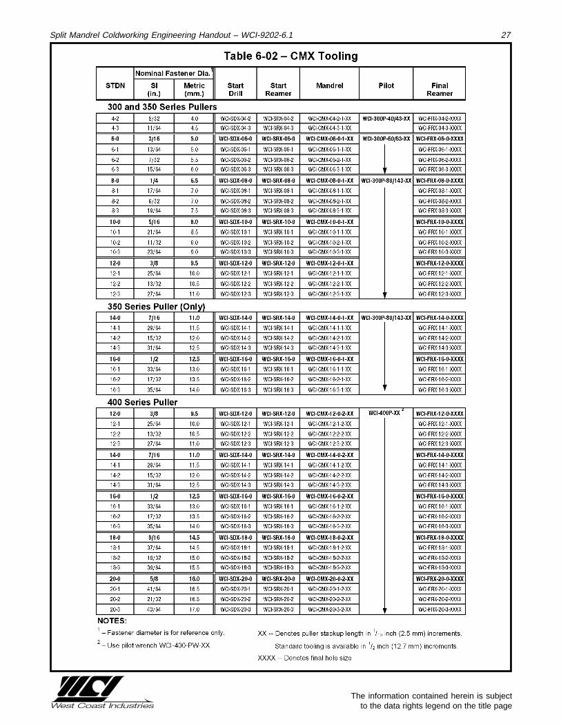
4.3.5.1. Expendable tooling consists of the following items: split-mandrels, pilots, nosecaps, drills, reamers, gages,inspection pins, and pilot wrench. They are grouped according to puller unit (Ref. Tables 5-02 and 6-02).Part numbers for individual tools are tabulated according to coldworking process, puller unit, and hole sizein the following tables.
4.3.5.2. Nosecap If the hole has no access restrictions, select the flush nosecap. If the hole has a front or lateralaccess restriction, select the extension nosecap.
4.3.5.3. Expendable CMS and CMX tooling are not interchangeable.
4.4. Hole Preparation
4.4.1. Holes which require coldworking in accordance with this specification shall be indicated on the drawing bya note similar to the following:
“0.309 to 0.310 inch [or "7.85 to 7.87 mm"] diameter hole. Cold-work in accordance with WCI-PS-9601 or equivalent engineer-ing specification.”
4.4.2. The hole diameters indicated on the drawings apply to the final hole size after coldworking and post-reaming if required.
4.4.3. Start hole diameters shall be determined per Table 5-01 for the CMS process, and Table 6-01 for the CMXprocess.
4.4.4. WCI recommends that start holes be drilled and reamed (when required) using a drill bushing in a toolingfixture such as a drill plate, drill table, drill block, or drill jig.
The information contained herein is subject to the data rights legend on the title page
Split Mandrel Coldworking Engineering Handout – WCI-9202-6.1 16
4.4.5. Drill and/or ream the existing hole to the start hole dimensions described for the particular final hole sizein Tables 5-01 or 6-01. The start hole shall be cleaned of all paint, sealant, and any other foreign material.
4.4.6. Start holes shall have a maximum surface roughness value of 125 microinches (3.2 micrometers) orbetter, with a circular lay and no longitudinal scratches, galling, or rifling.
4.4.7. Perpendicularity of the start hole to the surface where the manufactured head of the fastener is to beinstalled shall be maintained within two degrees. WCI offers a line of gages to insure proper angularity ofa hole. Contact WCI for more information on these gages.
4.4.8. Bell mouthing, ovality, or barreling of the start hole shall be acceptable, provided the applicable holetolerance limits of Tables 5-01 and 6-01 are not exceeded.
4.4.9. Internal measurement tools with a minimum accuracy of +/- 0.0005 inch (0.0127 mm) and two contactpoints for measurements shall be the preferred tool to check start holes for bell mouthing, ovality, barrel-ing, or stepping. All measurement tools shall be regularly calibrated. One hundred percent of all start holesshall be inspected prior to coldworking.
4.5. Tool Assemb ly
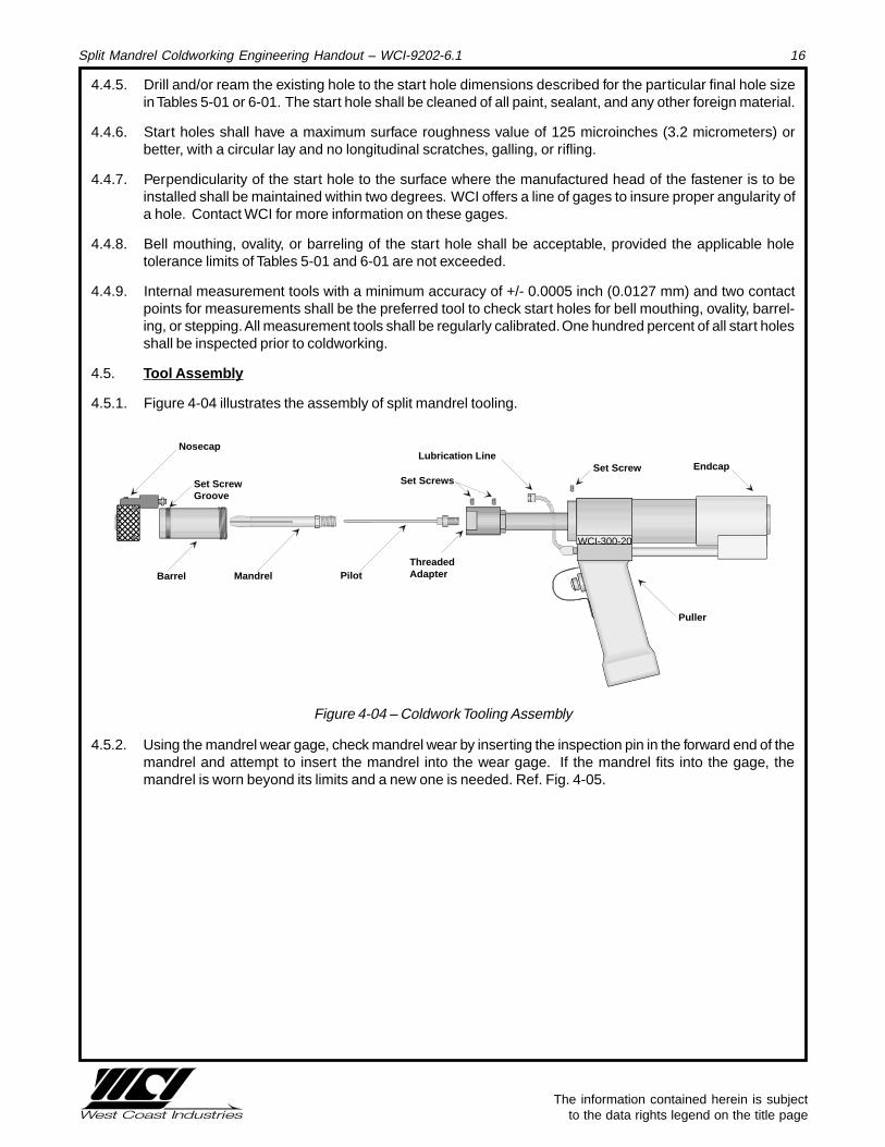
4.5.1. Figure 4-04 illustrates the assembly of split mandrel tooling.
ThreadedAdapterMandrel Pilot
Nosecap
WCI-300-20
�
Puller
Set ScrewGroove
������
Barrel
Lubrication LineSet Screw
Set ScrewsEndcap
Figure 4-04 – Coldwork Tooling Assembly
4.5.2. Using the mandrel wear gage, check mandrel wear by inserting the inspection pin in the forward end of themandrel and attempt to insert the mandrel into the wear gage. If the mandrel fits into the gage, themandrel is worn beyond its limits and a new one is needed. Ref. Fig. 4-05.

The information contained herein is subject to the data rights legend on the title page
Split Mandrel Coldworking Engineering Handout – WCI-9202-6.1 17
������
NO-GO
����
Acceptable
Unacceptable
Mandrel Wear Gage Block
Inspection PinNote: Dimensions exaggerated for clarity
������
Figure 4-05 – Checking for Mandrel Wear
NOTETHE USE OF NONCONFORMING OR WORN TOOLING WILL
REDUCE FATIGUE LIFE IMPROVEMENT OR POSSIBLY
RESULT IN EXTENSIVE REWORK
4.5.3. Connect the hydraulic powerpak to an air line with a nominal pressure of 90 psi (620 kPa) of clean, dry air.Use filters, if necessary, to prevent oil or moisture from entering the powerpak through the air line.
4.5.4. With the nosecap, barrel, and mandrel removed, install the pilot into the puller unit with the pilot wrench.Hold the outer wrench stationary, while turning the inner wrench, thus screwing the pilot into the puller unit.The pilot needs to be only finger tight.
4.5.5. Install the mandrel by placing it over the pilot and inserting the threaded end into the threaded adapter andtightening the set screw. The mandrel needs to be only finger tight.
4.5.6. Place barrel over mandrel and securely thread into puller unit. Tighten set screw.
4.5.7. Install the nosecap assembly over the mandrel and onto the barrel. Tighten set screws. Connect lube lineto nosecap assembly.
4.5.8. Connect the hose assembly lines from the puller unit to the powerpak. Ensure that the couplings are tight.
4.5.9. Functionally test the puller unit by depressing the trigger. The test is successful if the mandrel is drawncompletely into the nosecap of the puller unit. A mandrel not drawing into the nosecap sufficiently may becaused by a failure to thread the mandrel completely into the threaded adapter or selection of an incorrectmandrel length. Refer to the equipment operating manuals for troubleshooting information.
4.5.10. Remove any trapped air present in the hydraulic system by fully cycling the puller unit at least three times.Sluggish cylinder action in the puller unit is usually the first sign of trapped air in the system. Whentrapped air is removed from the hydraulic circuit, the tool will advance and retract smoothly.
4.6. Pre-Coldwork Hole Preparation
4.6.1. When the “Go” portion of either the start hole or combination gage will not enter the hole, the hole isconsidered undersize and is not acceptable. A tight fit through the entire hole is a good indication that thehole is within tolerance.
The information contained herein is subject to the data rights legend on the title page
Split Mandrel Coldworking Engineering Handout – WCI-9202-6.1 18
4.6.2. If the “No-Go” gage can enter the hole, the hole is oversize and not acceptable. If this occurs contactQuality Assurance/Control personnel for instructions.
4.7. General Coldworking Procedure
4.7.1. Check the structure visually and, where possible, with a 0.002 inch (0.05 mm) feeler gage, to ensure thatno gaps exist as a result of burrs from drilling and reaming operations. If gaps exist, separate thestructure’s components and deburr.
4.7.2. For stackups greater than 1.00" (25.4 mm), lubricate the hole.
4.7.3. Insert the mandrel into the hole until the nosecap is seated against the workpiece.
4.7.4. Activate the puller unit by squeezing the trigger.
4.8. Post-Cold working
4.8.1. Coldworked holes shall be identified with the operator’s stamp on the part or assembly immediately aftercoldworking. The operator’s stamp shall also be applied to the accompanying manufacturing paperwork tomaintain traceability of coldworking operations.
4.8.2. Check the hole, and coldwork tooling visually for galling and other damage due to improper coldworkingprocesses.
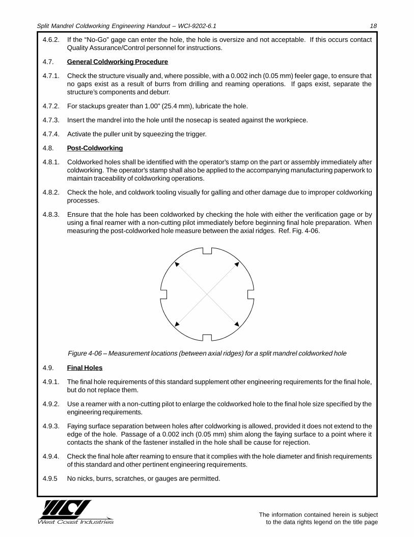
4.8.3. Ensure that the hole has been coldworked by checking the hole with either the verification gage or byusing a final reamer with a non-cutting pilot immediately before beginning final hole preparation. Whenmeasuring the post-coldworked hole measure between the axial ridges. Ref. Fig. 4-06.
Figure 4-06 – Measurement locations (between axial ridges) for a split mandrel coldworked hole
4.9. Final Holes
4.9.1. The final hole requirements of this standard supplement other engineering requirements for the final hole,but do not replace them.
4.9.2. Use a reamer with a non-cutting pilot to enlarge the coldworked hole to the final hole size specified by theengineering requirements.
4.9.3. Faying surface separation between holes after coldworking is allowed, provided it does not extend to theedge of the hole. Passage of a 0.002 inch (0.05 mm) shim along the faying surface to a point where itcontacts the shank of the fastener installed in the hole shall be cause for rejection.
4.9.4. Check the final hole after reaming to ensure that it complies with the hole diameter and finish requirementsof this standard and other pertinent engineering requirements.
4.9.5 No nicks, burrs, scratches, or gauges are permitted.
The information contained herein is subject to the data rights legend on the title page
Split Mandrel Coldworking Engineering Handout – WCI-9202-6.1 19
4.9.6. After the hole has been reamed to final size, visually check the area around the hole, including all fayingsurfaces, for gaps resulting from upset material. When access allows, also check for gaps using a 0.002inch (0.05 mm) feeler gage. Upset material may occur as far as one final hole diameter away from theedge of the final hole. When upset material is detected, remove it per paragraph 4.10.
4.9.7. The final hole may contain a region near the entry, exit, or faying surface interfaces which does not totally“clean-up” during the final reaming operation. The final hole shall be acceptable, provided the axial lengthof this region is not longer than 0.020 inch (0.50 mm) or 10 percent of the stackup thickness, whichever isless.
4.10. Upset Material Removal
4.10.1. Prior to fastener installation, an area at least one final hole diameter distance around the final hole,including all faying surfaces, shall be checked for upset material.
4.10.2. When gaps are detected between mating surfaces of joints due to material upset around the coldworkedhole, the upset material shall be removed by sanding until the applicable flat surface specified per engi-neering requirement is achieved.
4.10.3. When the removal of upset material results in bare metal on finished surfaces or the removal of fayingsurface sealant, the part or assembly shall be refinished per the requirements of the engineering drawingor, if not specified by the drawing, per the requirements of the applicable finish specification, and resealedper the requirements of the engineering drawing. When removal of upset material will result in bare metalon plated surfaces, contact Quality Assurance/Control personnel.
4.10.4. Bulging from coldworking on the edge of the part shall be acceptable, unless the bulging will cause a lackof fit on the next assembly.
4.11. Rework
4.11.1 Holes require rework if Paragraph 4.9 requirements are not satisfied.
4.11.2 Re-coldwork is not required if the oversize hole diameter is less than or equal to the maximum allowablehole size in accordance with the applicable table. Quality Assurance/Control approval is required.
4.11.3 Re-coldwork is required if the oversize hole diameter exceeds the maximum allowable hole size in accor-dance with the applicable table. Re-coldwork shall be performed in accordance with paragraphs 4.4. through4.9. Quality Assurance/Control approval is required.
4.11.4 All rework shall be documented as required by the applicable Quality Assurance/Control provisions.

The information contained herein is subject to the data rights legend on the title page
Split Mandrel Coldworking Engineering Handout – WCI-9202-6.1 20
5.0 – CMS Process Tables

The information contained herein is subject to the data rights legend on the title page
Split Mandrel Coldworking Engineering Handout – WCI-9202-6.1 21
Table 5-01 – CMS Process Hole ParametersFastener Start Hole
STDN Nom. Dia. (1) Final Hole Maximum 2000 Series 7000 Series
Fraction Dec Min Dia Max Dia Allow. Dia (2) Min Dia Max Dia Min Dia Max Dia
4-1 9/64 0.1406 0.1400 0.1554 0.1580 0.1280 0.1300 0.1280 0.1300
4-2 5/32 0.1562 0.1555 0.1709 0.1730 0.1430 0.1450 0.1430 0.1450
4-3 11/64 0.1719 0.1710 0.1864 0.1890 0.1590 0.1610 0.1590 0.1610
6-0 3/16 0.1875 0.1865 0.1994 0.2060 0.1740 0.1760 0.1760 0.1780
6-1 13/64 0.2031 0.1995 0.2149 0.2170 0.1855 0.1875 0.1875 0.1895
6-2 7/32 0.2188 0.2150 0.2304 0.2330 0.2010 0.2030 0.2030 0.2050
6-3 15/64 0.2344 0.2305 0.2464 0.2480 0.2160 0.2180 0.2180 0.2200
8-0 1/4 0.2500 0.2465 0.2619 0.2647 0.2320 0.2340 0.2345 0.2365
8-1 17/64 0.2656 0.2620 0.2774 0.2840 0.2480 0.2500 0.2500 0.2520
8-2 9/32 0.2812 0.2775 0.2929 0.2950 0.2630 0.2650 0.2650 0.2670
8-3 19/64 0.2969 0.2930 0.3089 0.3110 0.2790 0.2810 0.2810 0.2830
10-0 5/16 0.3125 0.3090 0.3244 0.3272 0.2945 0.2965 0.2970 0.2990
10-1 21/64 0.3281 0.3245 0.3399 0.3425 0.3105 0.3125 0.3125 0.3145
10-2 11/32 0.3438 0.3400 0.3554 0.3575 0.3255 0.3275 0.3275 0.3295
10-3 23/64 0.3594 0.3555 0.3714 0.3735 0.3415 0.3435 0.3435 0.3455
12-0 3/8 0.3750 0.3715 0.3869 0.3897 0.3575 0.3595 0.3590 0.3610
14-0 7/16 0.4375 0.4340 0.4490 0.4522 0.4155 0.4175 0.4165 0.4185
Note: All dimensions in inches
(1) -- Fastener Nominal Diameter is for reference only.
(2) -- Maximum Allowable Diameter that can be reamed while still retaining the desired coldworking benefit.
The information contained herein is subject to the data rights legend on the title page
Split Mandrel Coldworking Engineering Handout – WCI-9202-6.1 22
Table 5-02 – CMS Tooling
Fastener Nom. Dia. (1)
Fraction Decimal Start Start Mandrel Pilot (2) Final
STDN (in.) (in.) Drill Reamer Reamer
300 and 350 Series Pullers4-0 1/8 0.1250 WCI-SDM-04-0 WCI-SRM#-04-0 WCI-CMS-04-0-XX WCI-300P-40/43-XX WCI-FRM#-04-0-XXXX
4-1 9/64 0.1406 WCI-SDM-04-1 WCI-SRM#-04-1 WCI-CMS-04-1-XX WCI-FRM#-04-1-XXXX
4-2 5/32 0.1562 WCI-SDM-04-2 WCI-SRM#-04-2 WCI-CMS-04-2-XX WCI-FRM#-04-2-XXXX
4-3 11/64 0.1719 WCI-SDM-04-3 WCI-SRM#-04-3 WCI-CMS-04-3-XX WCI-FRM#-04-3-XXXX
6-0 3/16 0.1875 WCI-SDM-06-0 WCI-SRM#-06-0 WCI-CMS-06-0-XX WCI-300P-60/63-XX WCI-FRM#-06-0-XXXX
6-1 13/64 0.2031 WCI-SDM-06-1 WCI-SRM#-06-1 WCI-CMS-06-1-XX WCI-FRM#-06-1-XXXX
6-2 7/32 0.2188 WCI-SDM-06-2 WCI-SRM#-06-2 WCI-CMS-06-2-XX WCI-FRM#-06-2-XXXX
6-3 15/64 0.2344 WCI-SDM-06-3 WCI-SRM#-06-3 WCI-CMS-06-3-XX WCI-FRM#-06-3-XXXX
8-0 1/4 0.2500 WCI-SDM-08-0 WCI-SRM#-08-0 WCI-CMS-08-0-XX WCI-300P-80/143-XX WCI-FRM#-08-0-XXXX
8-1 17/64 0.2656 WCI-SDM-08-1 WCI-SRM#-08-1 WCI-CMS-08-1-XX WCI-FRM#-08-1-XXXX
8-2 9/32 0.2812 WCI-SDM-08-2 WCI-SRM#-08-2 WCI-CMS-08-2-XX WCI-FRM#-08-2-XXXX
8-3 19/64 0.2969 WCI-SDM-08-3 WCI-SRM#-08-3 WCI-CMS-08-3-XX WCI-FRM#-08-3-XXXX
10-0 5/16 0.3125 WCI-SDM-10-0 WCI-SRM#-10-0 WCI-CMS-10-0-XX WCI-FRM#-10-0-XXXX
10-1 21/64 0.3281 WCI-SDM-10-1 WCI-SRM#-10-1 WCI-CMS-10-1-XX WCI-FRM#-10-1-XXXX
10-2 11/32 0.3438 WCI-SDM-10-2 WCI-SRM#-10-2 WCI-CMS-10-2-XX WCI-FRM#-10-2-XXXX
10-3 23/64 0.3594 WCI-SDM-10-3 WCI-SRM#-10-3 WCI-CMS-10-3-XX WCI-FRM#-10-3-XXXX
12-0 3/8 0.3750 WCI-SDM-12-0 WCI-SRM#-12-0 WCI-CMS-12-0-XX WCI-FRM#-12-0-XXXX
14-0 7/16 0.4375 WCI-SDM-14-0 WCI-SRM#-14-0 WCI-CMS-14-0-XX WCI-FRM#-14-0-XXXX
NOTES:1 Fastener diameter is for reference only. XX -- Denotes puller stackup length in 1/10 increments.
2 Use pilot wrench WCI-300-PW-XX Standard tooling is available in 1/2 inch increments
# -- Denotes aluminum alloy being coldworked. XXXX -- Denotes final hole size
Insert a 2 for 2000 series and a 7 for 7000 series.
The information contained herein is subject to the data rights legend on the title page
Split Mandrel Coldworking Engineering Handout – WCI-9202-6.1 23
Table 5-02 – CMS Tooling (cont.)
Mandrel
Flush Extension Combination Wear Inspection Pilot
STDN Nosecap Nosecap Gage Gage Pin Wear Gage
300 and 350 Series Pullers4-0 WCI-300N-04-0 WCI-300EN-04-0 WCI-CBGM#-04-0 WCI-WG-04-0 WCI-IP-40/43 WCI-300-PDW-40/43
4-1 WCI-300N-04-1 WCI-300EN-04-1 WCI-CBGM#-04-1 WCI-WG-04-1
4-2 WCI-300N-04-2 WCI-300EN-04-2 WCI-CBGM#-04-2 WCI-WG-04-2
4-3 WCI-300N-04-3 WCI-300EN-04-3 WCI-CBGM#-04-3 WCI-WG-04-3
6-0 WCI-300N-06-0 WCI-300EN-06-0 WCI-CBGM#-06-0 WCI-WG-06-0 WCI-IP-60/63 WCI-300-PDW-60/63
6-1 WCI-300N-06-1 WCI-300EN-06-1 WCI-CBGM#-06-1 WCI-WG-06-1
6-2 WCI-300N-06-2 WCI-300EN-06-2 WCI-CBGM#-06-2 WCI-WG-06-2
6-3 WCI-300N-06-3 WCI-300EN-06-3 WCI-CBGM#-06-3 WCI-WG-06-3
8-0 WCI-300N-08-0 WCI-300EN-08-0 WCI-CBGM#-08-0 WCI-WG-08-0 WCI-IP-80/143 WCI-300-PDW-80/143
8-1 WCI-300N-08-1 WCI-300EN-08-1 WCI-CBGM#-08-1 WCI-WG-08-1
8-2 WCI-300N-08-2 WCI-300EN-08-2 WCI-CBGM#-08-2 WCI-WG-08-2
8-3 WCI-300N-08-3 WCI-300EN-08-3 WCI-CBGM#-08-3 WCI-WG-08-3
10-0 WCI-300N-10-0 WCI-300EN-10-0 WCI-CBGM#-10-0 WCI-WG-10-0
10-1 WCI-300N-10-1 WCI-300EN-10-1 WCI-CBGM#-10-1 WCI-WG-10-1
10-2 WCI-300N-10-2 WCI-300EN-10-2 WCI-CBGM#-10-2 WCI-WG-10-2
10-3 WCI-300N-10-3 WCI-300EN-10-3 WCI-CBGM#-10-3 WCI-WG-10-3
12-0 WCI-300N-12-0 WCI-300EN-12-0 WCI-CBGM#-12-0 WCI-WG-12-0
14-0 WCI-300N-14-0 WCI-300EN-14-0 WCI-CBGM#-14-0 WCI-WG-14-0
NOTES:# -- Denotes aluminum alloy being coldworked.
Insert a 2 for 2000 series and a 7 for 7000 series.

The information contained herein is subject to the data rights legend on the title page
Split Mandrel Coldworking Engineering Handout – WCI-9202-6.1 24
6.0 – CMX Process Tables
The information contained herein is subject to the data rights legend on the title page
Split Mandrel Coldworking Engineering Handout – WCI-9202-6.1 25
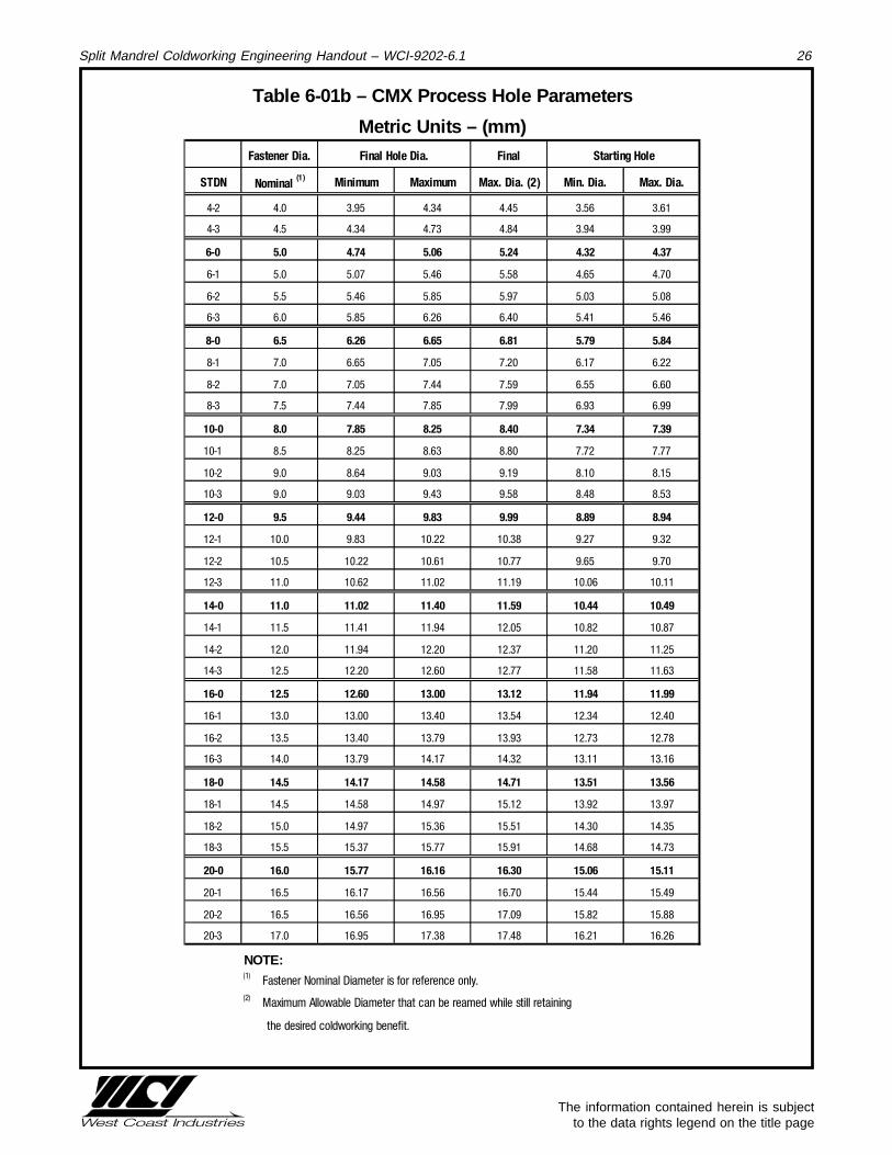
Table 6-01a – CMX Process Hole Parameters
SI Units – (inches)
Fastener Nom. Dia. (1)
Final Hole Dia. Final Starting Hole
STDN Fraction Decimal Minimum Maximum Max. Dia. (2) Min. Dia. Max. Dia.
4-2 5/32 0.1562 0.1555 0.1709 0.1750 0.140 0.142
4-3 11/64 0.1719 0.1710 0.1864 0.1906 0.155 0.157
6-0 3/16 0.1875 0.1865 0.1994 0.2061 0.170 0.172
6-1 13/64 0.2031 0.1995 0.2149 0.2195 0.183 0.185
6-2 7/32 0.2188 0.2150 0.2304 0.2350 0.198 0.200
6-3 15/64 0.2344 0.2305 0.2464 0.2520 0.213 0.215
8-0 1/4 0.2500 0.2465 0.2619 0.2680 0.228 0.230
8-1 17/64 0.2656 0.2620 0.2774 0.2835 0.243 0.245
8-2 9/32 0.2812 0.2775 0.2929 0.2989 0.258 0.260
8-3 19/64 0.2969 0.2930 0.3089 0.3144 0.273 0.275
10-0 5/16 0.3125 0.3090 0.3247 0.3309 0.289 0.291
10-1 21/64 0.3281 0.3248 0.3399 0.3464 0.304 0.306
10-2 11/32 0.3438 0.3400 0.3554 0.3619 0.319 0.321
10-3 23/64 0.3594 0.3555 0.3714 0.3773 0.334 0.336
12-0 3/8 0.3750 0.3715 0.3869 0.3932 0.350 0.352
12-1 25/64 0.3906 0.3870 0.4024 0.4087 0.365 0.367
12-2 13/32 0.4062 0.4025 0.4179 0.4241 0.380 0.382
12-3 27/64 0.4219 0.4180 0.4339 0.4407 0.396 0.398
14-0 7/16 0.4375 0.4340 0.4490 0.4562 0.411 0.413
14-1 29/64 0.4531 0.4491 0.4699 0.4746 0.426 0.428
14-2 15/32 0.4688 0.4700 0.4804 0.4871 0.441 0.443
14-3 31/64 0.4844 0.4805 0.4959 0.5026 0.456 0.458
16-0 1/2 0.5000 0.4960 0.5119 0.5165 0.470 0.472
16-1 33/64 0.5156 0.5120 0.5274 0.5329 0.486 0.488
16-2 17/32 0.5312 0.5275 0.5429 0.5484 0.501 0.503
16-3 35/64 0.5469 0.5430 0.5579 0.5638 0.516 0.518
18-0 9/16 0.5625 0.5580 0.5739 0.5790 0.532 0.534
18-1 37/64 0.5781 0.5740 0.5894 0.5954 0.548 0.550
18-2 19/32 0.5938 0.5895 0.6049 0.6108 0.563 0.565
18-3 39/64 0.6094 0.6050 0.6209 0.6263 0.578 0.580
20-0 5/8 0.6250 0.6210 0.6364 0.6417 0.593 0.595
20-1 41/64 0.6406 0.6365 0.6519 0.6573 0.608 0.610
20-2 21/32 0.6562 0.6520 0.6674 0.6728 0.623 0.625
20-3 43/64 0.6719 0.6675 0.6844 0.6882 0.638 0.640
NOTE:(1) Fastener Nominal Diameter is for reference only.(2) Maximum Allowable Diameter that can be reamed while still retaining
the desired coldworking benefit.
The information contained herein is subject to the data rights legend on the title page
Split Mandrel Coldworking Engineering Handout – WCI-9202-6.1 26
Table 6-01b – CMX Process Hole Parameters
Metric Units – (mm)Fastener Dia. Final Hole Dia. Final Starting Hole
STDN Nominal (1)
Minimum Maximum Max. Dia. (2) Min. Dia. Max. Dia.
4-2 4.0 3.95 4.34 4.45 3.56 3.61
4-3 4.5 4.34 4.73 4.84 3.94 3.99
6-0 5.0 4.74 5.06 5.24 4.32 4.37
6-1 5.0 5.07 5.46 5.58 4.65 4.70
6-2 5.5 5.46 5.85 5.97 5.03 5.08
6-3 6.0 5.85 6.26 6.40 5.41 5.46
8-0 6.5 6.26 6.65 6.81 5.79 5.84
8-1 7.0 6.65 7.05 7.20 6.17 6.22
8-2 7.0 7.05 7.44 7.59 6.55 6.60
8-3 7.5 7.44 7.85 7.99 6.93 6.99
10-0 8.0 7.85 8.25 8.40 7.34 7.39
10-1 8.5 8.25 8.63 8.80 7.72 7.77
10-2 9.0 8.64 9.03 9.19 8.10 8.15
10-3 9.0 9.03 9.43 9.58 8.48 8.53
12-0 9.5 9.44 9.83 9.99 8.89 8.94
12-1 10.0 9.83 10.22 10.38 9.27 9.32
12-2 10.5 10.22 10.61 10.77 9.65 9.70
12-3 11.0 10.62 11.02 11.19 10.06 10.11
14-0 11.0 11.02 11.40 11.59 10.44 10.49
14-1 11.5 11.41 11.94 12.05 10.82 10.87
14-2 12.0 11.94 12.20 12.37 11.20 11.25
14-3 12.5 12.20 12.60 12.77 11.58 11.63
16-0 12.5 12.60 13.00 13.12 11.94 11.99
16-1 13.0 13.00 13.40 13.54 12.34 12.40
16-2 13.5 13.40 13.79 13.93 12.73 12.78
16-3 14.0 13.79 14.17 14.32 13.11 13.16
18-0 14.5 14.17 14.58 14.71 13.51 13.56
18-1 14.5 14.58 14.97 15.12 13.92 13.97
18-2 15.0 14.97 15.36 15.51 14.30 14.35
18-3 15.5 15.37 15.77 15.91 14.68 14.73
20-0 16.0 15.77 16.16 16.30 15.06 15.11
20-1 16.5 16.17 16.56 16.70 15.44 15.49
20-2 16.5 16.56 16.95 17.09 15.82 15.88
20-3 17.0 16.95 17.38 17.48 16.21 16.26
NOTE:(1) Fastener Nominal Diameter is for reference only.(2) Maximum Allowable Diameter that can be reamed while still retaining
the desired coldworking benefit.
The information contained herein is subject to the data rights legend on the title page
Split Mandrel Coldworking Engineering Handout – WCI-9202-6.1 27

The information contained herein is subject to the data rights legend on the title page
Split Mandrel Coldworking Engineering Handout – WCI-9202-6.1 28
The information contained herein is subject to the data rights legend on the title page
Split Mandrel Coldworking Engineering Handout – WCI-9202-6.1 29
7.0 – Split Mandrel Countersink Extension Nosecap
7.1 WCI has developed a new nosecap that enables users to use the split mandrel system to coldworkpreviously countersunk holes in repair applications. The new nosecap supports, but does not coldwork,the countersink surface. Only the straight portion of the hole is coldworked.
7.2 The nosecap is used with either the CMS or CMX split mandrel process.
7.3 The same general coldworking process is used for the countersunk holes.
7.4 The nosecap is only available in the extended version.
7.5 Use the following part number when ordering:
WCI-XX0ENXC-XX-X where:
XX0 denotes puller model, either 300 (includes 350), or 400
-XX - X denotes Standard Tool Code (e.g., 08-0, 10-1)
For more information, contact WCI.
The information contained herein is subject to the data rights legend on the title page
Split Mandrel Coldworking Engineering Handout – WCI-9202-6.1 30
8.0 – Safety
8.1. Always keep fingers clear of the area between the front of the nosecap and the workpiece.
8.2. Release the puller unit trigger when the mandrel clears the workpiece and the puller unit is removed fromthe structure.
8.3. To avoid injury or damage to the equipment, always disconnect the air supply while working on the unit andensure that all air and hydraulic connections are tight before checking the operation of the unit.

The information contained herein is subject to the data rights legend on the title page
Split Mandrel Coldworking Engineering Handout – WCI-9202-6.1 31
9.0 – Quality Assurance/Control
9.1. Facility Requirements All measurement tools and gaging shall show evidence of valid calibration statusprior to use.
9.2. Process Control Provide supervision as necessary to verify compliance with this standard and otherapplicable engineering requirements with particular attention to the following:
9.2.1. Personnel performing coldworking operations meet the requirements of paragraph 4.1.2. of this document.
9.2.2. Appropriate tools and equipment have been selected and used in accordance with the applicable tablesand requirements of this document.
9.2.3. Coldworking of holes is performed in accordance with the process requirements of this document.
9.2.4. Complete faying surface contact is maintained during hole preparation, coldworking and final hole sizing inaccordance with paragraph 4.1.3.3 of this standard.
9.2.5. Setup specimens are used in conjunction with appropriate tools and equipment to check for satisfactorycoldworked holes prior to coldworking production parts in the instances outlined in paragraph 4.2.1.
9.2.6. Mandrel diameters are checked for the acceptable minimum diameter with a mandrel wear gage prior tousage on each hole or group of holes to be coldworked.
9.2.7. Start holes comply with paragraphs 4.4 through 4.9 and have been checked per paragraph 4.6, prior tocoldworking.
9.2.8. All metal chips, burrs, and foreign material are removed from the inside of the start hole before beginningcoldworking operations.
9.2.9. Aluminum backup blocks are used in accordance with the requirements of paragraph 4.1.3.2 of thisstandard.
9.2.10. Cracks due to coldworking, visible without magnification, are cause for rejection.
9.2.11. Coldworked holes and the accompanying manufacturing paperwork, are identified with the operator’s stampper paragraph 4.8.1 immediately after coldworking.
9.2.12. Coldworked holes, and the split mandrels, are visually examined for evidence of galling or cracks.
9.2.13. Final holes are prepared in accordance with paragraph 4.9.
9.3. Acceptance Inspection
9.3.1. Inspect as necessary to verify conformance to engineering drawing with particular attention that finishedhole dimensions meet the requirements of this standard and the applicable engineering drawing.
Characteristic Acceptable Quality Level (AQL %)In accordance with MIL-STD105 or equivalent
Start Hole Diameter 1.5
Finished Hole Diameter(1) 2.5
Surface Defects Faying Surface Separation 2.5
All Other Engineering Requirements 4.0(1) Measured In at least two positions, with a 90º separation
Table 9.1: Acceptable Quality Levels