spm-d11 synchronizing unit - cee - spm-d11 manual.pdf · the prime mover control device(s) ......
TRANSCRIPT

37259E
Manual from Software version 6.3xx
Manual 37259E
SPM-D11 Synchronizing Unit

Manual 37259E SPM-D11 - Synchronizing Unit
Page 2/82 © Woodward
WARNING Read this entire manual and all other publications pertaining to the work to be performed before instal-ling, operating, or servicing this equipment. Practice all plant and safety instructions and precautions. Failure to follow instructions can cause personal injury and/or property damage. The engine, turbine, or other type of prime mover should be equipped with an overspeed (overtempe-rature, or overpressure, where applicable) shutdown device(s), that operates totally independently of the prime mover control device(s) to protect against runaway or damage to the engine, turbine, or oth-er type of prime mover with possible personal injury or loss of life should the mechanical-hydraulic governor(s) or electric control(s), the actuator(s), fuel control(s), the driving mechanism(s), the lin-kage(s), or the controlled device(s) fail. Any unauthorized modifications to or use of this equipment outside its specified mechanical, electric-al, or other operating limits may cause personal injury and/or property damage, including damage to the equipment. Any such unauthorized modifications: (i) constitute "misuse" and/or "negligence" with-in the meaning of the product warranty thereby excluding warranty coverage for any resulting damage, and (ii) invalidate product certifications or listings.
CAUTION To prevent damage to a control system that uses an alternator or battery-charging device, make sure the charging device is turned off before disconnecting the battery from the system. Electronic controls contain static-sensitive parts. Observe the following precautions to prevent dam-age to these parts. • Discharge body static before handling the control (with power to the control turned off, contact a
grounded surface and maintain contact while handling the control). • Avoid all plastic, vinyl, and Styrofoam (except antistatic versions) around printed circuit boards. • Do not touch the components or conductors on a printed circuit board with your hands or with
conductive devices.
OUT-OF-DATE PUBLICATION This publication may have been revised or updated since this copy was produced. To verify that you have the latest revision, be sure to check the Woodward website: http://www.woodward.com/pubs/current.pdf The revision level is shown at the bottom of the front cover after the publication number. The latest version of most publications is available at: http://www.woodward.com/publications If your publication is not there, please contact your customer service representative to get the latest copy.
Important definitions
WARNING Indicates a potentially hazardous situation that, if not avoided, could result in death or serious injury.
CAUTION Indicates a potentially hazardous situation that, if not avoided, could result in damage to equipment.
NOTE Provides other helpful information that does not fall under the warning or caution categories.
Woodward reserves the right to update any portion of this publication at any time. Information provided by Woodward is believed to be correct and reliable. However, Woodward assumes no responsibility unless otherwise expressly undertaken.
© Woodward
All Rights Reserved.

Manual 37259E SPM-D11 - Synchronizing Unit
© Woodward Page 3/82
Revision History
Rev. Date Editor Change B 04-08-04 TP LSR/LSXR update C 04-10-19 TP 1/3-phase measurement functionality updated; linguistic update D 06-03-28 TP Minor corrections; Load/var sharing updated; Package harmonization E 11-06-29 TE Minor corrections
Contents
CHAPTER 1. GENERAL INFORMATION ....................................................................................... 6
CHAPTER 2. ELECTROSTATIC DISCHARGE AWARENESS ............................................................ 7
CHAPTER 3. INSTALLATION ...................................................................................................... 8 Wiring Diagram ........................................................................................................................................ 9
SPM-D11/LSR ................................................................................................................................ 9 SPM-D11/LSXR ........................................................................................................................... 10
Reference Point ...................................................................................................................................... 11 Power Supply ......................................................................................................................................... 11 Measuring Inputs .................................................................................................................................... 12
Voltage ......................................................................................................................................... 12 Current ......................................................................................................................................... 13
Discrete Inputs ....................................................................................................................................... 14 Analog Inputs ......................................................................................................................................... 15 Relay Outputs ......................................................................................................................................... 16 Controller Outputs .................................................................................................................................. 17
SPM-D11/LSR .............................................................................................................................. 17 SPM-D11/LSXR ........................................................................................................................... 18
CHAPTER 4. DESCRIPTION OF FUNCTIONS .............................................................................. 20 Functional Description ............................................................................................................................ 20
Table for Terminal 6 = "Enable Control" ...................................................................................... 20 Table for Terminal 6 = "Enable Power Set point Value 2" ........................................................... 21 Additional Conditions ................................................................................................................... 22
Control Inputs ......................................................................................................................................... 23 Isolation of the Power Supply from the Discrete Inputs.......................................................................... 24 Operating Conditions .............................................................................................................................. 25
No Load Control ........................................................................................................................... 25 Synchronization ............................................................................................................................ 25 Synch-Check ................................................................................................................................ 26 Isolated Operation ........................................................................................................................ 26 Closing the CB Without Synchronization (Dead Bus Start) ......................................................... 26 Shutdown ..................................................................................................................................... 27 Mains Parallel Operation .............................................................................................................. 27 Load Sharing ................................................................................................................................ 27 var Sharing ................................................................................................................................... 28 LED "Gen CB - ON" Flashes........................................................................................................ 28
Control Outputs ...................................................................................................................................... 29 Analog Controller Outputs ...................................................................................................................... 30

Manual 37259E SPM-D11 - Synchronizing Unit
Page 4/82 © Woodward
CHAPTER 5. DISPLAY AND OPERATING ELEMENTS .................................................................. 33 Brief Explanation of the LEDs and Push Buttons .................................................................................. 34
LEDs ............................................................................................................................................ 34 Buttons ........................................................................................................................................ 34 Others .......................................................................................................................................... 34
LEDs ...................................................................................................................................................... 35 Push Buttons.......................................................................................................................................... 37 LC Display .............................................................................................................................................. 38
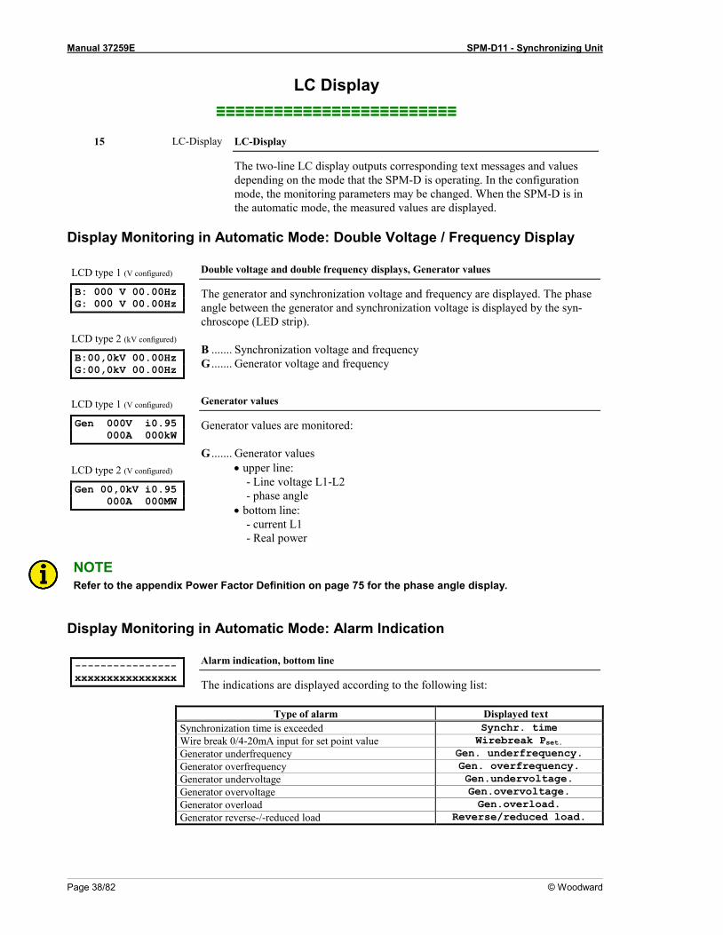
Display Monitoring in Automatic Mode: Double Voltage / Frequency Display ............................. 38 Display Monitoring in Automatic Mode: Alarm Indication ............................................................ 38
CHAPTER 6. CONFIGURATION ................................................................................................. 39 Configure Basic Data ............................................................................................................................. 39
Password Protection .................................................................................................................... 40 Direct Configuration ..................................................................................................................... 41
Configure Basic Settings ....................................................................................................................... 42 Potential Transformer .................................................................................................................. 42 Current Transformer .................................................................................................................... 43
Configure Controller ............................................................................................................................... 44 Idle Control .................................................................................................................................. 44 Frequency Controller ................................................................................................................... 44 Voltage Controller ........................................................................................................................ 48 Power Factor Control ................................................................................................................... 51 Real Power Controller.................................................................................................................. 53 Load/Var Sharing ......................................................................................................................... 57
Synchronization...................................................................................................................................... 58 Configure Synchronization ........................................................................................................... 58 Synchronization Time Monitoring ................................................................................................ 60
Dead Bus Start....................................................................................................................................... 61 Configure Monitoring.............................................................................................................................. 62
Generator Reverse/Reduced Power Monitoring .......................................................................... 62 Generator Overload Monitoring ................................................................................................... 63 Generator Frequency Monitoring ................................................................................................. 64 Generator Voltage Monitoring ..................................................................................................... 65 Auto Acknowledge Messages ..................................................................................................... 65
Password Configuration ......................................................................................................................... 66
CHAPTER 7. COMMISSIONING ................................................................................................. 67
APPENDIX A. DIMENSIONS ..................................................................................................... 69
APPENDIX B. TECHNICAL DATA .............................................................................................. 70
APPENDIX C. LIST OF PARAMETERS ....................................................................................... 72
APPENDIX D. POWER FACTOR DEFINITION .............................................................................. 75
APPENDIX E. SERVICE OPTIONS ............................................................................................. 77 Product Service Options ........................................................................................................................ 77 Returning Equipment for Repair ............................................................................................................ 77
Packing a Control ........................................................................................................................ 78 Return Authorization Number RAN ............................................................................................. 78
Replacement Parts ................................................................................................................................ 78 How to contact Woodward ..................................................................................................................... 79 Engineering Services ............................................................................................................................. 80 Technical Assistance ............................................................................................................................. 81

Manual 37259E SPM-D11 - Synchronizing Unit
© Woodward Page 5/82
Illustrations and Tables
Illustrations Figure 3-1: Wiring diagram SPM-D11/LSR ............................................................................................................................... 9 Figure 3-2: Wiring diagram SPM-D11/LSXR .......................................................................................................................... 10 Figure 3-3: Reference point ...................................................................................................................................................... 11 Figure 3-4: Power supply .......................................................................................................................................................... 11 Figure 3-5: Measuring inputs - Generator ................................................................................................................................. 12 Figure 3-6: Measuring inputs - Synchronization voltage .......................................................................................................... 13 Figure 3-7: Measuring inputs - Current .................................................................................................................................... 13 Figure 3-8: Digital inputs .......................................................................................................................................................... 14 Figure 3-9: Analog inputs ......................................................................................................................................................... 15 Figure 3-10: Load sharing ......................................................................................................................................................... 15 Figure 3-11: Relay outputs - control outputs I (CB control) ..................................................................................................... 16 Figure 3-12: Relay outputs - control outputs II (acknowledgements) ....................................................................................... 16 Figure 3-13: Controller - SPM-D11/LSR - three-position controller ........................................................................................ 17 Figure 3-14: Controller - SPM-D11/LSXR - three-position controller ..................................................................................... 18 Figure 3-15: Controller - SPM-D11/LSXR - Analog controller output - Speed/frequency/real power .................................... 19 Figure 3-16: Controller - SPM-D11/LSXR - Analog controller output - Voltage/power factor ............................................... 19 Figure 4-1: Control loop ........................................................................................................................................................... 30 Figure 4-2: Step response (example) ......................................................................................................................................... 30 Figure 4-3: Step response - controller set-up ............................................................................................................................ 32 Figure 5-1: Front foil ................................................................................................................................................................ 33 Figure 7-1: Dimensions ............................................................................................................................................................. 69
Tables Table 3-1: Conversion chart - wire size ...................................................................................................................................... 8 Table 4-1: Operating conditions - Terminal 6 = "Enable control" ............................................................................................ 20 Table 4-2: Operating conditions - Terminal 6 = "OFF" ............................................................................................................ 21 Table 4-3: Operating conditions - status of measuring inputs and configuration ...................................................................... 22 Table 4-4: Power set point modes ............................................................................................................................................. 27

Manual 37259E SPM-D11 - Synchronizing Unit
Page 6/82 © Woodward
Chapter 1. General Information
The SPM-D11 is a synchronizing unit with integrated control functions for generator power levels and load shar-ing. Through the application of appropriate logic to the discrete inputs the following functions can be realized: • Synchronization • Synch-check • Black start • Load/var control • Load/var sharing The SPM-D starts as a standard unit that may have additional functions added with each package. The model of the SPM-D is designated as follows: SPM-D11 4 5 B/ xx
Packages according to the Package list. These packages can be found in the manual. Each headline points out if the described function is standard or part of a package.
Mounting
[B].. Flush-mounting
CT's, current transformers, secondary [1] = ../1 A [5] = ../5 A
Voltage transformers/PT's, secondary [1] = 100 Vac [4] = 400 Vac
Type
Examples: • SPM-D1145B/LSR (LSR package with 400 Vac PT measuring inputs and ../5 A CT measuring inputs) • SPM-D1111B/LSXR (LSXR package with 100 Vac PT measuring inputs and ../1 A CT measuring inputs) Intended Use The control must only be operated for the uses described in this manual. The prerequisite for a proper and safe operation of the product is correct transportation, storage and installation, as well as careful oper-ation and maintenance.
NOTE This manual has been developed for a control fitted with all available options. Inputs/outputs, func-tions, configuration screens and other details described, which do not exist on your control, may be ignored. The present manual has been prepared to enable the installation and commissioning of the control. Due to the large variety of parameter settings, it is not possible to cover every combination. The ma-nual is therefore only a guide. In case of incorrect entries or a total loss of functions, the default set-tings can be taken from the list of parameters located in the rear of this manual.
Manual 37259E SPM-D11 - Synchronizing Unit
© Woodward Page 7/82
Chapter 2. Electrostatic Discharge Awareness
All electronic equipment is static-sensitive, some components more than others. To protect these components from static damage, you must take special precautions to minimize or eliminate electrostatic discharges. Follow these precautions when working with or near the control. 1. Before performing maintenance on the electronic control, discharge the static electricity on your body to
ground by touching and holding a grounded metal object (pipes, cabinets, equipment, etc.). 2. Avoid the build-up of static electricity on your body by not wearing clothing made of synthetic materials.
Wear cotton or cotton-blend materials as much as possible because these do not store static electric charges as much as synthetics.
3. Keep plastic, vinyl, and Styrofoam materials (such as plastic or Styrofoam cups, cup holders, cigarette
packages, cellophane wrappers, vinyl books or folders, plastic bottles, and plastic ash trays) away from the control, the modules, and the work area as much as possible.
4. Opening the control cover may void the unit warranty.
Do not remove the Printed Circuit Board (PCB) from the control cabinet unless absolutely necessary. If you must remove the PCB from the control cabinet, follow these precautions:
• Ensure that the device is completely de-energized (all connectors must be disconnected).
• Do not touch any part of the PCB except the edges.
• Do not touch the electrical conductors, connectors, or components with conductive devices with your
hands.
• When replacing a PCB, keep the new PCB in the protective antistatic bag it comes in until you are ready to install it. Immediately after removing the old PCB from the control cabinet, place it in the pro-tective antistatic bag.
CAUTION To prevent damage to electronic components caused by improper handling, read and observe the pre-cautions in Woodward manual 82715, Guide for Handling and Protection of Electronic Controls, Printed Circuit Boards, and Modules.

Manual 37259E SPM-D11 - Synchronizing Unit
Page 8/82 © Woodward
Chapter 3. Installation
WARNING A circuit breaker must be located near to the control and in a position easily accessible to the opera-tor. This must also bear a sign identifying it as an isolating switch for the control.
NOTE Inductive devices connected to the system (such as operating current coils, undervoltage tripping units, or auxiliary/power contacts) must be connected to a suitable interference suppressor.
WARNING All technical data and ratings indicated in this chapter are not definite! Only the values indicated in Appendix B: Technical Data on page 70 are valid!
The following chart may be used to convert square millimeters [mm²] to AWG and vice versa:
AWG mm² AWG mm² AWG mm² AWG mm² AWG mm² AWG mm² 30 0.05 21 0.38 14 2.5 4 25 3/0 95 600MCM 300 28 0.08 20 0.5 12 4 2 35 4/0 120 750MCM 400 26 0.14 18 0.75 10 6 1 50 300MCM 150 1000MCM 500 24 0.25 17 1.0 8 10 1/0 55 350MCM 185 22 0.34 16 1.5 6 16 2/0 70 500MCM 240
Table 3-1: Conversion chart - wire size

Manual 37259E SPM-D11 - Synchronizing Unit
© Woodward Page 9/82
Wiring Diagram ≡≡≡≡≡≡≡≡≡≡≡≡≡≡≡≡≡≡≡≡≡≡≡≡≡
SPM-D11/LSR
s1 (k)
Reference point (terminal 29/30)
14
Command: close CB
2423
3
alternatively
3
Subject to technical modifications.
L1
L2 Mains voltage orBusbar voltage
153
411
2120
1013
128
9
CB
3
CB
alternatively
3Dr
iveG
Reply: CB is open
Enable CB
Generator voltage
Common (term. 3, 4, 5, 6)
Release isolated operation / dead bus
Release control orSetpoint power
0
2006-01-26 | SPM-D11 Wiring Diagram spmd11ww-0406-ap.SKF
15
26
Ready for operation
719
18
- Power supply
+ Power supply (refer to label for actual rating Vaux)
The
sock
et fo
r the
PC
conf
igura
tion
is sit
uate
d on
the
side
of th
e un
it.
SPEED / REAL POWERThree-position controller
VOLTAGE / POWER FACTORThree-position controller
lower
raise
raise
lower
L1
L2
Battery#
SPM
-D11
/LSR
(Syn
chro
nizing
Unit
)
2625
Generator current L1s2 (l)
Load sharing 29 SPM-D11
var sharing 30 SPM-D11
External real power setpoint valueGND
2827
3940 Command: open CB
(for shutdown)16
1738
3742
4144
43N.O.
N.C.
N.C.
N.C.
N.C.
Powerlimit value
Reverse/reduced poweroverload
Generator overvoltagegenerator undervoltage
Generator overfrequencygenerator underfrequency
0 to 4 Vdc
0 to 4 Vdc
0 to 20 mA
N.O.
N.O.
All relays are open if the unit is de-energizedN.O.: The relay closes if the command is issued or the function is fulfilledN.C.: The relay opens if the function is triggered
Figure 3-1: Wiring diagram SPM-D11/LSR
Manual 37259E SPM-D11 - Synchronizing Unit
Page 10/82 © Woodward
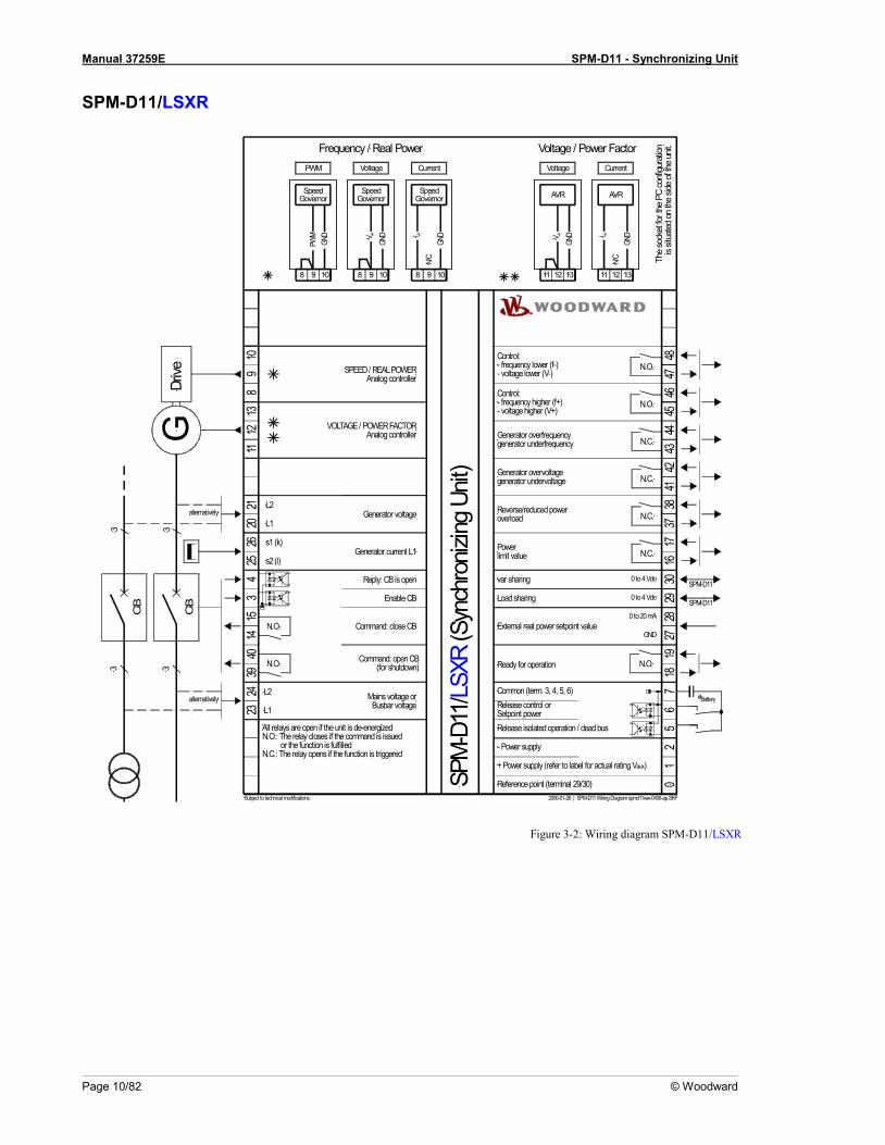
SPM-D11/LSXR
s1 (k)
Reference point (terminal 29/30)
14
Command: close CB
2423
3
alternatively
3
Subject to technical modifications.
L1
L2 Mains voltage orBusbar voltage
153
411
2120
1013
128
9
CB
3
CB
alternatively
3Dr
iveG
Reply: CB is open
Enable CB
Generator voltage
SPEED / REAL POWERAnalog controller
VOLTAGE / POWER FACTORAnalog controller
Common (term. 3, 4, 5, 6)
Release isolated operation / dead bus
Release control orSetpoint power
0
2006-01-26 | SPM-D11 Wiring Diagram spmd11ww-0406-ap.SKF
15
26
Ready for operation7
1918
- Power supply
+ Power supply (refer to label for actual rating Vaux)
The
sock
et fo
r the
PC
conf
igura
tion
is sit
uate
d on
the
side
of th
e un
it.
8 109
Current
SpeedGovernor
AIN/
CGN
D
Voltage
SpeedGovernor
A
GND
PWM
SpeedGovernor
GND
PWM
L1
L2
Battery#
8 109 8 109 11 1312
Current
AIN/
CGN
D
Voltage
A
GND
AVRAVR
11 1312
SPM
-D11
/LSX
R (S
ynch
roniz
ing U
nit)
2625
Generator current L1s2 (l)
Voltage / Power FactorFrequency / Real Power
Load sharing 29 SPM-D11
var sharing 30 SPM-D11
External real power setpoint valueGND
2827
3940 Command: open CB
(for shutdown)16
1738
3742
4144
4346
4548
47N.O.
N.C.
N.C.
N.C.
N.C.
Powerlimit value
Reverse/reduced poweroverload
Generator overvoltagegenerator undervoltage
Generator overfrequencygenerator underfrequency
N.O.Control:- frequency higher (f+)- voltage higher (V+)
Control:- frequency lower (f-)- voltage lower (V-)
N.O.
VV
0 to 4 Vdc
0 to 4 Vdc
0 to 20 mA
N.O.
N.O.
All relays are open if the unit is de-energizedN.O.: The relay closes if the command is issued or the function is fulfilledN.C.: The relay opens if the function is triggered
Figure 3-2: Wiring diagram SPM-D11/LSXR

Manual 37259E SPM-D11 - Synchronizing Unit
© Woodward Page 11/82
Reference Point ≡≡≡≡≡≡≡≡≡≡≡≡≡≡≡≡≡≡≡≡≡≡≡≡≡
0 Reference point Figure 3-3: Reference point
Terminal Description Amax
0 Reference point: Neutral point of the three-phase system or neutral terminal of the voltage transformer (Measuring reference point); with three-conductor (delta) systems, do not connect
Sold.lug
Power Supply ≡≡≡≡≡≡≡≡≡≡≡≡≡≡≡≡≡≡≡≡≡≡≡≡≡
WARNING There are two different versions of this unit with different voltage input ratings. Look at the DATA PLATE of the unit to determine the correct voltage input ratings. An incorrect power supply may de-stroy the unit. The voltage input ratings are:
• Vaux = 24 Vdc • Vaux = 12/24 Vdc
24 Vdc12/24 Vdc
21
0 Vdc24 Vdc / 12/24 Vdc Power supply
Figure 3-4: Power supply
Terminal Description Amax 1 +24 Vdc or +12/24Vdc 2.5 mm² 2 0 Vdc 2.5 mm²

Manual 37259E SPM-D11 - Synchronizing Unit
Page 12/82 © Woodward
Measuring Inputs ≡≡≡≡≡≡≡≡≡≡≡≡≡≡≡≡≡≡≡≡≡≡≡≡≡
NOTE The unit always assumes a clockwise three-phase system (right-handed rotary field). If the unit is used with a counter-clockwise field (left-handed rotary field), the power factor measurement will not be cor-rect. This may be compensated by adapting the angle adjustment (refer to Current Transformer section on page 43).
Voltage
NOTE The SPM-D11 can only operate (monitor) one synchronization point (one power circuit breaker), due to the 1-power-circuit-breaker configuration. The measured voltage at terminals 23/24 is the voltage ref-erence point for the synchronization at terminals 20/21. The synchronization reference voltage can be the mains or busbar voltage.
NOTE There are generally three variations for connection of the measuring circuit voltage: Direct connection to a low voltage system Connection to medium voltage via two-phase isolated transformer (e. g. in the case of a delta connection) Connection to medium voltage via single- phase isolated transformer (e. g. Y-connection). The SPM-D11 may be connected to L1/L2 or L1/N. Regardless of what connection is used, the genera-tor and mains/busbar must always be connected identically. Correct measured values can be achieved for three-phase and single-phase systems if the SPM-D11 is configured accordingly (refer to Current Transformer section on page 43).
Generator
Generatorvoltage
020
21
G
L2L1
123
MCB
L2L1
L3N
GCB
Figure 3-5: Measuring inputs - Generator
Note: Connection corresponding to the mains configuration (see wiring diagram)
Terminal Measurement Description Amax
Connection of the measuring circuit voltage corresponding to the variant , or 20
direct or Transformer
../100 V
Generator voltage L1 2.5 mm² 21 Generator voltage L2 2.5 mm²
0
Reference point: N-terminal of the low voltage system or star point of the voltage transducer (measuring reference point); do not connect in delta connection installa-tions
Solder.lug

Manual 37259E SPM-D11 - Synchronizing Unit
© Woodward Page 13/82
Mains/Busbar
GCB
Synchronizingvoltage
G
L2L123
24
123
N
L1L2L3
231
MCB
Figure 3-6: Measuring inputs - Synchronization voltage
Note: Connection corresponding to the Bus configuration (see wiring diagram).
Terminal Measurement Description Amax
Connection of the measuring circuit voltage corresponding to variant , or 23 direct
or ../100 V Synchronization ref. voltage L1 2.5 mm²
24 Synchronization ref. voltage L2 2.5 mm²
Current
WARNING Before disconnecting the secondary terminals of the current transformer or the connections of the current transformer at the unit, ensure that the transformer is short-circuited.
NOTE Current transducers are generally to be grounded on one side of the secondary.
N
L2L3
L1
Generator current../1 A or ../5 A
MCB
2625
s1 (k)s2 (l)
L1
GCB
GS2 S1s2 s1
Figure 3-7: Measuring inputs - Current
Terminal Measurement Description Amax 25 Transformer
../1 A o. ../5 A
Generator current L1, transformer terminal s2 (l) 2.5 mm²
26 Generator current L1, transformer terminal s1 (k) 2.5 mm²
NOTE If the generator load is always symmetrically, the current may also be measured in L2 or L3. This must be considered when configuring the SPM-D11 (refer to Current Transformer section on page 43). If there is a possibility that the load may be asymmetrical, the current must be measured in L1.

Manual 37259E SPM-D11 - Synchronizing Unit
Page 14/82 © Woodward
Discrete Inputs ≡≡≡≡≡≡≡≡≡≡≡≡≡≡≡≡≡≡≡≡≡≡≡≡≡
WARNING There are two versions of this unit with different discrete inputs. The discrete inputs have different maximum voltage ratings. Look at the DATA PLATE of the unit to determine the correct voltage input ratings. Applying incorrect voltages to the discrete inputs may destroy the hardware. The voltage input ratings are: • VCont, dig. input = +/-18 to 250 Vac/dc • VCont, dig. input = 12/24 Vdc
Signal device
Digital inputBA
CBReply
Digital inputDC
3
+/-18 to 250 Vac/dc12/24 Vdc
Figure 3-8: Digital inputs
Terminal Associated zero-terminal
Description (to DIN 40 719 part 3, 5.8.3)
Amax
NO (make) contact A B 3
7 Enable CB 2.5 mm²
5 Enable isolated operation / dead bus start 2.5 mm² 6 Enable control or release power set point value 2 * 2.5 mm²
NC (break) contact C D 4 7 Reply: CB is open 2.5 mm²
* refer to parameter Parameter 14 "Terminal 6" on page 44

Manual 37259E SPM-D11 - Synchronizing Unit
© Woodward Page 15/82
Analog Inputs ≡≡≡≡≡≡≡≡≡≡≡≡≡≡≡≡≡≡≡≡≡≡≡≡≡
WARNING The analog inputs of the SPM-D are not isolated. When using an isolation monitor, we recommend to use two-pole, isolated transmitters. The analog inputs for active transmitters (0 to 20 mA, 0 to 10V) should only be operated with two-pole, isolated transmitters.
0 V0
AA Analog input0 to 4 V
0 V0
AIB Analog input0/4 to 20 mA
additional SPM-D11s V
Figure 3-9: Analog inputs
Terminal Associated zero-terminal
Description (to. DIN 40 719 part 3, 5.8.3)
Amax
0 to 4 Vdc A 29 0 Real power load sharing 2.5 mm² 30 Reactive power load sharing 2.5 mm²
0/4 to 20 mA B 28 27 Real power set point value 2.5 mm²
All controls that are load sharing must be interconnected via terminal 29 (terminals 30 must also be intercon-nected for var sharing). If an SPM-D11 is switched off, the load/var sharing line must be disconnected to prevent the disabled SPM-D11 from influencing the other controls.
additionalSPM-D11s
0 Vd
c
24 V
dc
Refe
renc
e po
int
Load
shar
ing
var s
harin
g
30 29 2 1 0
24 Vdc0 Vdc
SPM-D11Analog output
0 to 4 Vdc
0 Vd
c
24 V
dc
Refe
renc
e po
int
Load
shar
ing
var s
harin
g
30 29 2 1 0
SPM-D11Analog output
0 to 4 Vdc
0 Vd
c
24 V
dc
Refe
renc
e po
int
Load
shar
ing
var s
harin
g
30 29 2 1 0
SPM-D11Analog output
0 to 4 Vdc
Figure 3-10: Load sharing

Manual 37259E SPM-D11 - Synchronizing Unit
Page 16/82 © Woodward
Relay Outputs ≡≡≡≡≡≡≡≡≡≡≡≡≡≡≡≡≡≡≡≡≡≡≡≡≡
max. 250 V AC
ABexternal device Relay output
Figure 3-11: Relay outputs - control outputs I (CB control)
Root Switched Description Amax A B 14 15 Synchronizing pulse, Command: close CB 2.5 mm² 39 40 Command: open CB for shutdown 2.5 mm²
NOTE The relay "open CB for shutdown“ is used to automatically open the CB after the power has been re-duced (see also Control Outputs on page 29). This relay is not controlled by monitoring functions.
max. 250 V AC
ABexternal device Relay output
Figure 3-12: Relay outputs - control outputs II (acknowledgements)
Monitoring relay N.C. functionality Root Switched Description Amax
A B Note: The relays are de-energized and open in case of an fault.
37 38 Reverse/reduced load, overload 2.5 mm² 41 42 Generator over/under voltage 2.5 mm² 43 44 Generator over/under frequency 2.5 mm²
Signal relay N.O. functionality
Root Switched Description Amax A B Note: The relay is energized and closed when the
function is fulfilled.
18 19 Ready for operation 2.5 mm² N.C. functionality
Root Switched Description Amax A B Note: The relay will be de-energized and opens
when the power limit is exceeded.
16 17 Power limit 2.5 mm²

Manual 37259E SPM-D11 - Synchronizing Unit
© Woodward Page 17/82
Controller Outputs ≡≡≡≡≡≡≡≡≡≡≡≡≡≡≡≡≡≡≡≡≡≡≡≡≡
The SPM-D11/LSR is equipped with two three-position controllers for voltage and frequency (each comprising a form C and form A relay). The SPM-D11/LSXR permits various analog or PWM output signals to be selected by configuration, which can then be utilized in different ways.
SPM-D11/LSR max. 250 Vac
1112
13Voltagecontroller
Common
Raise
Lower
Voltage controller
8 Common
Speedcontroller Speed / frequency
controller
910 Lower
Raise
Figure 3-13: Controller - SPM-D11/LSR - three-position controller
Terminal Description Amax 8 common Speed/frequency controller
Real power controller
2.5 mm² 9 raise 2.5 mm²
10 lower 2.5 mm² 11 common Voltage controller
Power factor controller
2.5 mm² 12 raise 2.5 mm² 13 lower 2.5 mm²

Manual 37259E SPM-D11 - Synchronizing Unit
Page 18/82 © Woodward
SPM-D11/LSXR The SPM-D11/LSXR controller outputs can be configured for the following signals and may require the use of an external jumper between terminals.
Versions
NOTE Only one controller output may be configured as three-step controller.
- Three-step controller via relay manager
- Control of n/f: Parameter "f control type" = THREESTEP n+/f+ = Relay connected to terminals 45/46 n-/f- = Relay connected to terminals 47/48 - Control of V: parameter "V control type" = THREESTEP V+ = Relay connected to terminals 45/46 V- = Relay connected to terminals 47/48
- Analog controller output
- Control of n/f: Parameter "f control type" = ANALOG Current output (mA) = no external bridge/jumper necessary Voltage output (V) = external bridge/jumper between 8/9 Connect the Controller to terminals 9/10 - Control of V: Parameter "V control type" = ANALOG Current output (mA) = no external bridge/jumper necessary Voltage output (V) = external bridge/jumper between 11/12 Connect the controller to terminals 12/13
- PWM controller output
- Control of n/f: Parameter "f control type" = PWM PWM output = external bridge/jumper between 8/9 Connect the controller to terminals 9/10
Connection of the controllers
Setting: 'THREESTEP' (three-position controller)
The relay has to be decoupled.
AB Relay output
max. 250 Vac
Figure 3-14: Controller - SPM-D11/LSXR - three-position controller
Terminal Description Amax 45 raise Speed / Frequency controller
or Voltage controller
2.5 mm² 46 2.5 mm² 47 lower 2.5 mm² 48 2.5 mm²

Manual 37259E SPM-D11 - Synchronizing Unit
© Woodward Page 19/82
Setting: 'ANALOG' and 'PWM' (Analog Controller) - Frequency/real power controller
GND
Speed / powercontroller
810
9
GND
PWM
Spee
dGo
vern
or GNDPWM PWM
Speed / powercontroller
810
9 A
Volta
ge
Spee
dGo
vern
or
A
GND
Speed / powercontroller
8 AI
109
GND
Curre
nt
Spee
dGo
vern
or
AI
GNDN/C
VV
Figure 3-15: Controller - SPM-D11/LSXR - Analog controller output - Speed/frequency/real power
Type Terminal Description Amax
I Current
8 IA
Speed controller / Frequency controller / Real power controller
2.5 mm² 9 2.5 mm²
10 GND 2.5 mm²
V Voltage
8 2.5 mm² 9 VA 2.5 mm²
10 GND 2.5 mm²
PWM 8 2.5 mm² 9 PWM 2.5 mm²
10 GND 2.5 mm²
Setting: 'ANALOG' (Analog Controller) -Voltage / power factor controller
Voltage / re-activepower controller
11 AI
1312
GND
Curre
nt
AVR
AIN/C
GND
Voltage / re-activepower controller
1113
12 A
Volta
ge
A
GND GND
AVR VV
Figure 3-16: Controller - SPM-D11/LSXR - Analog controller output - Voltage/power factor
Type Terminal Description Amax
I Current
11 IA
Voltage controller Power factor cosphi controller
2.5 mm² 12 2.5 mm² 13 GND 2.5 mm²
V Voltage
11 2.5 mm² 12 VA 2.5 mm² 13 GND 2.5 mm²

Manual 37259E SPM-D11 - Synchronizing Unit
Page 20/82 © Woodward
Chapter 4. Description of Functions
Functional Description ≡≡≡≡≡≡≡≡≡≡≡≡≡≡≡≡≡≡≡≡≡≡≡≡≡
Table for Terminal 6 = "Enable Control" With this setting, the control can be used as an SPM-A. The status of the discrete inputs "Reply: CB is open" and "Enable CB" is displayed via the LEDs "Gen CB - ON" and "Gen CB free" on the pressure-sensitive front membrane. Additional to the input signals the conditions Table 4-3: Operating conditions - must be observed.
Input signal Operating condition Cond. Relay "Command: close CB"
Operating mode SPM-A
LED
"G
en-C
B O
N"
LED
"G
en C
B fr
ee"
Dis
cr. i
nput
term
. 5: "
Enab
le
Isol
ated
ope
ratio
n/ d
ead
star
t"
Dis
cret
e in
put t
erm
. 6
"Ena
ble
cont
rolle
r"
0 0 x 0 OFF or automatic idle control
- C1
OFF OFF OFF
0 0 x 1 Idle operation or synchronization
C A
OFF OFF CHECK
0 1 0 0 OFF A Slip or phase matching PERMISSIVE
0 1 0 1 Idle operation or synchronization
C A
OFF Slip or phase matching RUN
0 1 1 0 OFF A Synchro-Check -
0 1 1 1 Idle operation or
synchronization or dead bus start
C A B
- Slip or phase matching
dead bus start
RUN (extended)
1 x x 0 OFF - OFF -
1 0 0 1 Mains parallel operation or shut down
- E
OFF OFF -
1 1 0 1 Mains parallel operation - OFF -
1 1 1 1 Load/var sharing or Isolated operation
F D
OFF OFF -
1 0 1 1 Load/var sharing or isolated operation or
shut down
F D E
OFF OFF OFF
-
0: "OFF" / 1: "ON" / x: Signal of no significance (0 or 1) Table 4-1: Operating conditions - Terminal 6 = "Enable control"

Manual 37259E SPM-D11 - Synchronizing Unit
© Woodward Page 21/82
Table for Terminal 6 = "Enable Power Set point Value 2" The status of the digital inputs "Reply: CB is open" and "Enable CB" is displayed via the LEDs "GCB closed" and "Release GCB" on the pressure-sensitive front membrane. Additional to the input signals the conditions listed in Table 4-3: Operating conditions - must be observed.
Input signal Operating condition Cond. Relay "Command: close CB" LE
D
"Gen
-CB
ON
"
LED
"G
en C
B fr
ee"
Dis
cr. i
nput
term
. 5: "
Enab
le
Isol
ated
ope
ratio
n/ d
ead
star
t"
0 0 x OFF or idle operation
- C1
OFF OFF
0 1 0 Idle operation or synchronization
C A
OFF Slip or phase matching
0 1 1 Idle operation or
synchronization or dead bus start
C A B
OFF Slip or phase matching
Black start
1 0 0 Mains parallel operation or shut down
- E
OFF OFF
1 1 0 Mains parallel operation - OFF
1 1 1 Load/var sharing or isolated operation
F D
OFF OFF
1 0 1 Load/var sharing or isolated operation or
shut down
F D E
OFF OFF OFF
0: "OFF" / 1: "ON" / x: Signal of no significance (0 or 1) Table 4-2: Operating conditions - Terminal 6 = "OFF"

Manual 37259E SPM-D11 - Synchronizing Unit
Page 22/82 © Woodward
Additional Conditions The function of the control is also dependent, apart from the digital input signals, on the state of the available measured voltages. The particular function must also be enabled in configuration mode: Condition
A Synchronization Generator circuit breaker
- Generator and synchronization voltage must comply with the following: 50 % < V < 125 % of the rated voltage VN 80 % < f < 110 % of the rated frequency fN (after time monitoring expires, the synchronization will be aborted)
B Dead bus Generator circuit breaker
- Parameter "Dead bus GCB ON" - Synchronization voltage must be less then 5% of the rated voltage - Generator voltage and frequency must be within the configured limits of the dead
bus start
C1 Automatic no-load control
- Parameter "Automatic no-load control ON" - The frequency controller complies with the following conditions:
Generator voltage > 50 % of the rated voltage VN - The voltage controller complies with the following conditions:
Generator frequency > 90 % of the rated frequency fN
C No-load operation
- for f control: Generator voltage > 50 % of rated voltage VN
- for V control: Generator frequency > 90 % of rated frequency fN
D Isolated operation
- Generator voltage > 50 % of rated voltage VN - For voltage controller: Parameter "Voltage controller in no-load operation ON" - For frequency controller: Parameter "Frequency controller in isolated operation
ON". E Shut down - Parameter "Shut down ON"
F Load/var sharing control
- for load sharing: Parameter "Load sharing ON"
- for var sharing: Parameter "var sharing ON"
Table 4-3: Operating conditions - status of measuring inputs and configuration

Manual 37259E SPM-D11 - Synchronizing Unit
© Woodward Page 23/82
Control Inputs ≡≡≡≡≡≡≡≡≡≡≡≡≡≡≡≡≡≡≡≡≡≡≡≡≡
Release CB
Terminal 3 • Terminal 6 = "Release control"
A signal into this discrete input enables operation of the power circuit breaker. For tests during commissioning, ensuring that no voltage is ap-plied to this input will prevent the power circuit breaker from operating, even if the control functions are enabled.
• Terminal 6 = "Set point power" A signal into this discrete input enables the operation of the breaker and the control functions.
Reply:
CB is open Terminal 4
The status of the CB must be transmitted to the unit through this input. The input must be energized if the CB is open. The status of this input is checked for its plausibility and is signaled with the LED "Gen CB - ON".
Enable: Isolated opera-
tion/dead bus start Terminal 5
Energizing this input when the breaker is open enables a dead bus start. Energizing this input when the breaker is closed enables the frequency and voltage controllers for isolated operation or load sharing control.
Enable control
Enable Pset 2 Terminal 6
• Terminal 6 = "Release control" The frequency and voltage controllers are enabled by energizing this in-put. For tests during commissioning, ensuring that no voltage is applied to this input will prevent the power circuit breaker from operating, even if the control functions are enabled.
• Terminal 6 = "Set point power" The second set point value or the set point value via analog input is enabled.
CAUTION If several generators feed one busbar, it has to be ensured with external interlocking that only one of the generators is released for dead bus start at a time. If several generators are released for dead bus start at the same time, it may happen that the generator circuit breakers close at the same time, which might cause serious damage to the generators!

Manual 37259E SPM-D11 - Synchronizing Unit
Page 24/82 © Woodward
Isolation of the Power Supply from the Discrete Inputs ≡≡≡≡≡≡≡≡≡≡≡≡≡≡≡≡≡≡≡≡≡≡≡≡≡
NOTE Please observe the notes about the maximum voltage ratings in the section Discrete Inputs on page 14!
By means of appropriate external wiring, the common reference point of the discrete inputs (terminal 7) can be galvanically separated from the supply voltage (0 V, terminal 2) . This is necessary, for instance, if the discrete inputs are not to be controlled with +24 Vdc and a galvanic separation of the control voltage (e. g. 220 Vdc, 220 Vac) from the supply voltage needs to be ensured. Wiring should be made as follows: • Reference points connected with 0 V
Jumper between terminal 7 and terminal 2 (0 V) • Reference point of the discrete inputs potential-free:
Terminal 2: 0 V (supply voltage) Terminal 7: 0 V or N (control voltage)

Manual 37259E SPM-D11 - Synchronizing Unit
© Woodward Page 25/82
Operating Conditions ≡≡≡≡≡≡≡≡≡≡≡≡≡≡≡≡≡≡≡≡≡≡≡≡≡
No Load Control The generator voltage and generator frequency are adjusted to the configured set point values. The generator cir-cuit breaker is open.
Synchronization
Synchronization with slip The generator voltage will be corrected to the amplitude and frequency of the synchronization voltage. The close command for the power circuit breaker will be issued, taking into account the inherent switching delay. The syn-chronization is carried out under the following conditions (see also tables in chapter "Function" at page 20): • The control is in the automatic mode (LED "Automatic" lights up) • The synchronization is switched on • The voltages and frequencies are within the specified range • The input "Enable CB" is energized (if terminal 6 = OFF) • The input "Enable CB" is energized to enable the close command and the input "Release control" is energized,
to enable the control functions (if terminal 6 = Release control) • The input "Reply: CB is open" is energized • The synchronization time monitoring is not switched on or has not tripped
Phase Matching Synchronization The voltage controller will correct the generator voltage to the amplitude of the synchronization voltage. The fre-quency controller operates in two possible stages: • Frequency correction: - As long as the difference of the frequency between generator and busbar/mains does
not fall below the configured value "df start", the generator frequency is corrected to that of the busbar/mains. • Phase angle correction: - If the frequency difference between generator and busbar/mains is less than the value
"df start", the frequency controller adjusts the phase angle of the generator to that of the busbar/mains, in order to drive the phase difference to zero. The control of the phase angle is stopped only when the frequency dif-ference between the generator and the busbar/mains becomes greater then the value "df start" plus a fixed pro-grammed hysteresis of 0.8 Hz.
The close command for the power circuit breaker is issued under the following conditions: • The configured limits for voltage and frequency are met • The phase angle between the systems is less then the maximal permissible angle for at least the configured
time • The input "Enable CB" is energized (if terminal 6 = OFF) • The input "Enable CB" is energized, to enable the close command and the input "Release control" is ener-
gized, to enable the controls (if terminal 6 = Release control) • The input "Reply CB is open" is energized The close command is issued without consideration of the inherent switching delay. In the phase-angle-zero-control mode, the analog input should be selected for the frequency controller.

Manual 37259E SPM-D11 - Synchronizing Unit
Page 26/82 © Woodward
Synch-Check In this condition, the unit can be used as a check-synchronizer. No control is carried out. The relay "Command: CB close" remains energized, as long as the following conditions are met: • The configured limit for the voltage difference is met
(screen "synchronization dVmax) • The configured limits for the frequency difference are met
(screen "synchronization dfmax and dfmin") • The configured limit for the phase angle is met
(screen "slip synchroniz. phasemax") • The input "Reply: CB is open" is energized • The parameter "Terminal 6" is configured to "Release control" • The terminal 6 is not energized (the control is disabled) • The input "Enable isolated operation / dead bus start" is energized • The input "Enable CB" is energized The synchronization time monitoring is disabled.
Isolated Operation The generator voltage and frequency are controlled according to the configurable set point values. The generator breaker is closed. To activate the voltage controller, the parameter "volt. controller in isol. oper." must be set to "ON". To activate the frequency controller, the parameter "freq. controller in isol. oper." must be set to "ON". Additionally, the discrete input "Enable isolated operation / dead bus start" must be energized to enable isolated operation.
Closing the CB Without Synchronization (Dead Bus Start) A close command for the power circuit breaker will be output without synchronization if the following conditions are met: • The control is in the automatic mode (LED "Automatic" lights up) • The parameter "Gen. circ.break. Dead bus op." has been set to "ON" • The bus bar is not energized (VSS < 5 % VN) • The generator voltage and frequency are within the configured limits • The input "Enable isolated operation / dead bus start" is energized • The input "Enable CB" is energized • The input "Reply: CB is open" is energized
CAUTION If several participants in a power pool are enabled to perform a dead bus start, an external interlock must ensure that it is not possible for two or more units to perform a dead bus start.

Manual 37259E SPM-D11 - Synchronizing Unit
© Woodward Page 27/82
Shutdown If the parameter "Download and open GCB" has been configured as "ON", the controller can be configured to perform a shutdown function in the following manner: • Terminal 3 "Enable CB" is de-energized, initiating the shutdown • The power will be reduced according to the setting configured in "Power controller ramp" (refer to section
Power Set point Value on page 54) • When the real power falls below 10 % of the generator rated power, the relay "Command: open CB" will open
Mains Parallel Operation In mains parallel operation both circuit breakers are closed and the real power and the power factor cos phi are controlled to the configured set point values, provided that the controllers are configured to enabled. If the para-meter "terminal 6 = Release control" is set, terminal 6 must also be energized, so that the controllers operate.
Selection of the power set point value
• If the generator is connected in parallel with the mains via the CB, initially a partial load is assumed. • When the partial load pre-run is completed (or deactivated) the following table is valid for the selection of the
power set point mode: Parameter "Terminal 6"
Condition "Terminal 6"
Parameter "Power set point ex-
ternal"
active set point value
Release control x ON External: via 0 to 20 mA OFF Internal: Power controller Pset2
Set point power 1 ON External: via 0 to 20 mA OFF Internal: Power controller Pset2
0 x Internal: Power controller Pset1 0: "OFF" / 1: "ON" / x: Signal of no significance (0 or 1)
Table 4-4: Power set point modes
• If an external signal has been selected for the parameter "Power set point external", the correct signal type must be selected on the following configuration screen.
• The power set point upper limit must be configured as the value "Power controller P max" • The power set point lower limit must be configured as the value "Power controller P min" • The power set point has a configurable ramp rate. This slope can be configured in the parameter "Power con-
troller Ramp".
Load Sharing The SPM-D11 is designed so that when several generators are operating in parallel (isolated operation) on a common mains bus, the real power of the isolated system (in reference to the relevant rated load) is shared equally among the generators. Isolated/mains parallel operation. Each controller participating in load sharing influences the genset to which it is assigned in such a manner that the preset rated frequency (main control variable) remains constant. All units are interlinked via an analog signal against which any deviation in real power (generator power) can be determined for each genset. This control variable (secondary variable) is taken into consideration in controlling the frequency. The weighting, with which the secondary and the main control variable (= "reference variable") are processed, can be set via a weighting factor (parameters "Act. load share Factor"). In settled state, the isolated system has the set rated frequency, whereby the total real power (in reference to the relevant rated power) is subdivided equally amongst those gensets involved. Note – The frequency regulators of the generators must be suitably configured for parallel operation (i.e. droop operation mode)

Manual 37259E SPM-D11 - Synchronizing Unit
Page 28/82 © Woodward
Note – Other SPM-D11 units, which are not participating in load sharing, must not be connected to the load shar-ing signal line (terminal 29) Prerequisite – The following values and adjustments of each unit in the load sharing system must be identical • All units must have identical configured rated frequencies • All units must have the "Load sharing" function configured to "ON" • All units must have the same status signal for "Enable CB" (either all logic "1" or all logic "0") • All units must have the same status signal for "Reply: CB closed" (either all logic "1" or all logic "0") • Only one unit may have the parameter "Gen. circ.break. Dead bus op" configured as "ON" The "Gen. circ.break. Dead bus op" parameter can be enabled for several units, provided that a control is availa-ble to override the function via the digital inputs "Enable CB" or "Enable isolated parallel operation".
var Sharing The SPM-D11 is designed so that when several generators are operating in parallel (isolated operation) on a common mains bus, the reactive power of the isolated system (in reference to the relevant rated load) is shared equally among the generators. Isolated/mains parallel operation. Each controller participating in var sharing influences the genset to which it is assigned in such a manner that the preset rated voltage (main control variable) remains constant. All units are interlinked via an analog signal against which any deviation in reactive power (generator power) can be deter-mined for each genset. This control variable (secondary variable) is taken into consideration in controlling the voltage. The weighting, with which the secondary and the main control variable (= "reference variable") are processed, can be set via a weighting factor (parameters "React. load share Factor"). In settled state, the isolated system has the set rated voltage, whereby the total reactive power (in reference to the relevant rated power) is subdivided equally amongst those gensets involved. Note – The voltage regulators of the generators must be suitably configured for parallel operation (i.e. droop op-eration mode) Note – Other SPM-D11 units, which are not participating in var sharing, must not be connected to the load shar-ing signal line (terminal 30) Prerequisite – The following values and adjustments of each unit in the var sharing system must be identical • All units must have identically configured rated voltage • All units must have the parameter "Reactive power Load-share" configured as "ON" • All units must have the same status signal for "Enable CB" (either all logic "1" or all logic "0") • All units must have the same status signal for "Reply: CB closed" (either all logic "1" or all logic "0") The "Gen. circ.break. Dead bus op" parameter can be enabled for several units, provided that a control is availa-ble to override the function via the digital inputs "Enable CB" or "Enable isolated parallel operation".
LED "Gen CB - ON" Flashes LED "Gen CB - ON" flashes: Incorrect signal state of the "Reply: CB is open" on terminal 4. Possible faults: • Reply "closed" is present (= 0 V) and the generator and mains/busbar voltage not synchronized If the LED flashes, one must check to see whether the input on terminal 4 is wired correctly. If the terminal is wired correctly, there will be 0 V applied to the input when the power circuit breaker is closed.

Manual 37259E SPM-D11 - Synchronizing Unit
© Woodward Page 29/82
Control Outputs ≡≡≡≡≡≡≡≡≡≡≡≡≡≡≡≡≡≡≡≡≡≡≡≡≡
Synchronization pulse:
Command: Close CB Terminals 14/15
Energizing this relay will close the CB. The relay de-energizes after the close pulse is output. Exception: "Synch-check" operating mode.
Readiness for operation
Terminals 18/19 The relay contact is closed when the control is ready for operation. The relay will de-energize if any of the following occurs: a) The internal self-monitoring system signals an alarm condition. In this
case a trouble-free function of the control cannot be guaranteed and other appropriate corrective measures must be taken.
b) The synchronization time monitoring system is enabled and the confi-gured time has expired before synchronization has occurred.
Command: open CB
(for shut down) Terminal 39/40
The contact for this function is a N.O. contact. In normal operations, this contact is continuously energized. It is de-energized when the "Shut down" function is enabled. Prerequisites:
• The parameter "Download and open GCB" is configured to ON • The circuit breaker is closed
The controller can be configured to perform a shutdown function in the fol-lowing manner:
• Terminal 3 "Enable CB" is re-energized, initiating the shutdown • The power will be reduced • When the real power falls below 10 % of the generator rated power,
the relay "Command: open CB" will open This relay is reserved for shut down functions and operates independently from the watchdogs.
Power limit
Terminal 16/17 This relay serves for controlling the power to a configured limit. The relay opens when the power limit value is exceeded for the configured time and closes again, when the power falls below the limit value minus the confi-gured hysteresis. Using this relay, it is possible for example to disconnect loads or activate further generators.

Manual 37259E SPM-D11 - Synchronizing Unit
Page 30/82 © Woodward
Analog Controller Outputs ≡≡≡≡≡≡≡≡≡≡≡≡≡≡≡≡≡≡≡≡≡≡≡≡≡
The analog PID controller forms a closed-loop control loop together with the controlled system (usually a first-order lag element). The parameters of the PID controller (proportional-action coefficient KP, derivative-action time TV and reset time Tn) can be modified individually.
Kp T1
Controlled system (PT1)PID controller
Kpr Tn Tv
Lag element (Tt)
Influencinyquantity Tt
Figure 4-1: Control loop
If an abrupt disturbance variable is applied to the control loop, the reaction of the controlled system can be rec-orded at the output as a function of time (step response).
0 t/s
x
TT
1
0T
xx d
m
x d
x m
T
Rise time
OvershootSystem deviation
rise
rise
Tolerance band
Settling timesett
sett Figure 4-2: Step response (example)
Various values can be derived from the step response; these are required for adjusting the controller to its opti-mum setting: Rise time Trise: Period starting when the value of the control variable leaves a predefined tolerance range for this variable following a jump in the disturbance variable or reference input variable and ending the first time the val-ue re-enters this range. Settling time Tsett: Period starting when the value of the control variable leaves the predefined tolerance range for the control variable following a step in the disturbance variable or reference input variable and ending when the value re-enters this range permanently.

Manual 37259E SPM-D11 - Synchronizing Unit
© Woodward Page 31/82
Overshoot xm: Highest transient deviation from the set point value during the transition from one steady-state condition to a new steady-state condition, following a change in value of the disturbance variable or reference in-put variable (xm Optimal ≤ 10 %). Permanent control deviation xd: The resultant deviation between set point value and output variable in the steady-state condition (PID controller: xd = 0). From these values, the values KP, Tn and TV can be derived. It is possible, to determine the optimal controller set-tings by calculating compensation or adjustment of the time constants, T-sum rule, or symmetrical optimum. Oth-er setting procedures and information may be obtained from current literature.
CAUTION The following must be observed regarding the controller setting: • Ensure that the emergency shutdown system is ready for use. • While determining the critical frequency, pay attention to the amplitude and frequency. • If the two values change in an uncontrollable manner:
EMERGENCY SHUTDOWN Initial state: The initial state determines the start position of the controller. If the controller is switched off, the initial state can be used to output a fixed controller position. Even when the analog controller is switched off, the initial state can be freely adjusted (e.g. the speed controller can be controlled in a static manner). Controller output Initial state 000%
Initial state 0 to 100 %
Analog controller output setting with controller switched off. General settings: The setting rule described below only serves as an example. Whether this method is suitable for setting your particular control system is not and cannot be taken into account, as each controlled system be-haves uniquely. There are various methods of setting a controller. The setting rules of Ziegler and Nichols are explained below (determination for abrupt disturbances on the system input); this setting method assumes a pure lag element con-nected in series with a first-order lag system.

Manual 37259E SPM-D11 - Synchronizing Unit
Page 32/82 © Woodward
1. Controller operated as a P-only controller
(where Tn = ∞ [screen setting: Tn =0], TV = 0). 2. Increase gain KP (P gain) until the control loop oscillates continuously at KP = KPcrit.
CAUTION If the control starts to oscillate uncontrollably, perform an emergency shutdown and change the screen setting accordingly.
3. Measuring of the cycle duration Tcrit 4. Set the parameters: PID controller PI controller KP = 0,6 × KPcrit KP = 0,45 × KPcrit Tn = 0,5 × Tcrit Tn = 0,83 × Tcrit TV = 0,125 × Tcrit
Step response Controller setting Optimum (xm ≤ 10 %)
Controller setting Tcrit
Controller setting Incorrect
x
0 t/s 0
x
t/s
x
0 t/s Figure 4-3: Step response - controller set-up
Pr.-sensitivity Kp = 000
P gain (KP) Proportional-action coefficient 1 to 240
The proportional-action coefficient KP indicates the closed-loop control system gain. By increasing the gain, the response is increased to permit larger corrections to the variable to be controlled. The optimum setting depends on the behavior of the system. If the gain is too low, the control action becomes slow. If the gain is confi-gured too high, the result is excessive overshoot/undershoot of the desired value.
Reset time Tn = 00.0s
Reset time (Tn) 0.2 to 60.0 s
The reset time Tn represents the I-component of the PID controller. The reset time corrects for any offset (between set point and process variable) over time until the process variable and the set point are the same. This parameter defines how quickly the reset attempts to correct for any offset. If Tn is configured as 0.00 s, the I-component of the PID loop is disabled.
Derivative act. time Tv=0.00s
Derivative-action time (TV) 0.00 to 6.00 s
The derivative-action time TV represents the D-component of the PID controller. The D-component of the controller output becomes effective with large variations of the offset, e.g. in case of load-shedding. The lower the derivative-action time is configured, the higher the controller reaction is. If TV is configured as 0.00 s, the D-component of the PID loop is disabled.

Manual 37259E SPM-D11 - Synchronizing Unit
© Woodward Page 33/82
Chapter 5. Display and Operating Elements
The foil of the front plate is made of coated plastic. All keys have been designed as touch-sensitive membrane switch elements. The display is a LC-display, consisting of 2 rows each with 16 characters, which are indirectly il-luminated red. Contrast of the display is infinitely variable by a rotary potentiometer at the left side.
Gen CB - ON Bus CB - ON
Free
FreeAutomatic
CB close
Synchronizing SystemBus CB
Gen CB
f - f + V - V +
SPM-D
15
1234
5
10 11 12 13 14
9
8
7
6
Figure 5-1: Front foil

Manual 37259E SPM-D11 - Synchronizing Unit
Page 34/82 © Woodward
Brief Explanation of the LEDs and Push Buttons ≡≡≡≡≡≡≡≡≡≡≡≡≡≡≡≡≡≡≡≡≡≡≡≡≡
LEDs No Description Function 1 Bus CB Free Non-functional 2 Gen CB Free Enable CB 3 Automatic Automatic mode 4 CB close Close command to the CB issued 5 Synchroscope Display of phase position 6 f- Governor output: frequency lower (reduce speed) 7 f+ Governor output: frequency raise (increase speed) 8 V- Governor output: voltage lower (reduce excitation) 9 V+ Governor output: voltage raise (increase excitation) 10 Gen CB - ON Reply: CB is closed 11 Bus CB - ON Non-functional
Buttons No Description Function 12 Display↓ Scroll display 12 Select Confirm selection 13 Digit↑ Increase digit 14 Clear Acknowledge alarm 14 Cursor→ Shift input position one digit to the right
Others No Description Function 15 LC-Display LC-Display Potentiometer Adjust LCD contrast
Manual 37259E SPM-D11 - Synchronizing Unit
© Woodward Page 35/82
LEDs ≡≡≡≡≡≡≡≡≡≡≡≡≡≡≡≡≡≡≡≡≡≡≡≡≡
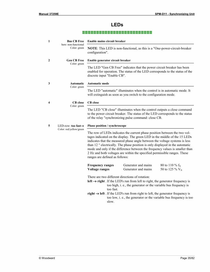
1 Bus CB Free
here: non-functional Color: green
Enable mains circuit breaker
NOTE: This LED is non-functional, as this is a "One-power-circuit-breaker configuration".
2 Gen CB Free
Color: green Enable generator circuit breaker
The LED "Gen CB Free" indicates that the power circuit breaker has been enabled for operation. The status of the LED corresponds to the status of the discrete input "Enable CB".
3 Automatic
Color: green Automatic mode
The LED "automatic" illuminates when the control is in automatic mode. It will extinguish as soon as you switch to the configuration mode.
4 CB close
Color: green CB close
The LED "CB close" illuminates when the control outputs a close command to the power circuit breaker. The status of the LED corresponds to the status of the relay "synchronizing pulse command: close CB.
5 LED-row: too fast→
Color: red/yellow/green Phase position / synchroscope
The row of LEDs indicates the current phase position between the two vol-tages indicated on the display. The green LED in the middle of the 15 LEDs indicates that the measured phase angle between the voltage systems is less than 12 ° electrically. The phase position is only displayed in the automatic mode and only if the difference between the frequency values is smaller than 2 Hz and both voltages are within the specified permissible ranges. These ranges are defined as follows: Frequency ranges Generator and mains 80 to 110 % fN Voltage ranges Generator and mains 50 to 125 % VN There are two different directions of rotation: left → right . If the LED's run from left to right, the generator frequency is
too high, i. e., the generator or the variable bus frequency is too fast.
right → left . If the LED's run from right to left, the generator frequency is too low, i. e., the generator or the variable bus frequency is too slow.

Manual 37259E SPM-D11 - Synchronizing Unit
Page 36/82 © Woodward
6 f-
Color: yellow Governor output decrease frequency
Three position controller The LED "f-" indicates if the control outputs a pulse to decrease the frequen-
cy. The status of the LED corresponds to the status of the relay "speed low-er".
Analog controller If the actuator output signal of the controller is changing to reduce the fre-quency, the LED illuminates.
7 f+
Color: yellow Governor output increase frequency
Three position controller The LED "f+" indicates if the control outputs a pulse to increase the fre-
quency. The status of the LED corresponds to the status of the relay "speed raise"."
Analog controller r If the actuator output signal of the controller is changing to increase the fre-quency, the LED illuminates.
8 V-
Color: yellow Governor output reduce voltage
Three-position controller The LED "V-" indicates if the control outputs a pulse to decrease voltage.
The status of the LED corresponds to the status of the relay "voltage lower".
Analog controller If the actuator output signal of the controller is changing to reduce the vol-tage, the LED illuminates.
9 V+
Color: yellow Governor output increase voltage
Three-position controller The LED "V+" indicates if the control outputs a pulse to increase voltage.
The status of the LED corresponds to the status of the relay "voltage raise".
Analog controller r If the actuator signal of the controller is changing to increase the voltage, the LED illuminates.
10 Gen CB - ON
Color: green Power circuit breaker ON
The LED "Gen CB - ON" signals the response of the generator circuit breaker. The LED illuminates if the discrete input "Reply: CB is open" is not energized and will extinguish as soon as the discrete input is energized. (see also chapter "LED "Gen CB - ON" Flashes" on page 28).
11 Bus CB – ON
here: non-functional Color: green
Mains power circuit breaker ON
NOTE: This LED is non-functional, as this is a "One-power-circuit-breaker configuration".

Manual 37259E SPM-D11 - Synchronizing Unit
© Woodward Page 37/82
Push Buttons ≡≡≡≡≡≡≡≡≡≡≡≡≡≡≡≡≡≡≡≡≡≡≡≡≡
Configuration may be performed by manually inputting the desired set points utilizing the pushbuttons and the LC display. In order to facilitate configuring the parameters, the push buttons have been enabled with an AUTOROLL function. This permits the user to advance to the next setting, configuration screen, digit, and/or cursor position more rapidly by pressing and holding the corresponding pushbutton.
12 Display / Select
Display / Select
Automatic mode: Display - By pressing this button, the user may navigate through the displayed measured parameters and alarm messag-es.
Configuration: Select - Advances the LC display to the next configuration screen. If any values in a configuration screen have been mod-ified with the "Digit↑" or "Cursor→", then the "Select" button must be pressed to save the new setting. By pressing this push-button again, the user causes the system to display the next configuration screen.
13 Digit↑
Digit ↑
Automatic mode: Digit↓ - no function Configuration: Digit↑ - Numerical values over the cursor are increased by
one digit. The increase is restricted by the admissible limits (re-fer to the list of parameters included in the appendix). If the maximum admissible number is reached, the number automati-cally returns to the lowest admissible number.
14 Clear / Cursor →
Clear / Cursor→
Automatic mode: Clear - Alarms that have occurred may be acknowledged by pressing this button as long as the fault that triggered the alarm is no longer present.
Configuration: Cursor→ - This button moves the cursor one position from left to right. When the cursor is under the last digit that may be changed, it may be moved to the first number of the value by pressing the "Cursor→" button again.
Manual 37259E SPM-D11 - Synchronizing Unit
Page 38/82 © Woodward
LC Display ≡≡≡≡≡≡≡≡≡≡≡≡≡≡≡≡≡≡≡≡≡≡≡≡≡
15 LC-Display LC-Display
The two-line LC display outputs corresponding text messages and values depending on the mode that the SPM-D is operating. In the configuration mode, the monitoring parameters may be changed. When the SPM-D is in the automatic mode, the measured values are displayed.
Display Monitoring in Automatic Mode: Double Voltage / Frequency Display LCD type 1 (V configured)
B: 000 V 00.00Hz G: 000 V 00.00Hz
LCD type 2 (kV configured)
B:00,0kV 00.00Hz G:00,0kV 00.00Hz
Double voltage and double frequency displays, Generator values
The generator and synchronization voltage and frequency are displayed. The phase angle between the generator and synchronization voltage is displayed by the syn-chroscope (LED strip). B ....... Synchronization voltage and frequency G ....... Generator voltage and frequency
LCD type 1 (V configured)
Gen 000V i0.95 000A 000kW
LCD type 2 (V configured)
Gen 00,0kV i0.95 000A 000MW
Generator values
Generator values are monitored: G ....... Generator values • upper line:
- Line voltage L1-L2 - phase angle • bottom line: - current L1 - Real power
NOTE Refer to the appendix Power Factor Definition on page 75 for the phase angle display.
Display Monitoring in Automatic Mode: Alarm Indication ---------------- xxxxxxxxxxxxxxxx
Alarm indication, bottom line
The indications are displayed according to the following list:
Type of alarm Displayed text Synchronization time is exceeded Synchr. time Wire break 0/4-20mA input for set point value Wirebreak Pset. Generator underfrequency Gen. underfrequency. Generator overfrequency Gen. overfrequency. Generator undervoltage Gen.undervoltage. Generator overvoltage Gen.overvoltage. Generator overload Gen.overload. Generator reverse-/-reduced load Reverse/reduced load.
Manual 37259E SPM-D11 - Synchronizing Unit
© Woodward Page 39/82
Chapter 6. Configuration
CAUTION Please note that configuration should not be carried out while the control unit is in operation.
NOTE A list of parameters may be found in the List of Parameters on page 72.
The configuration mode will be enabled through the front face panel by simultaneously pressing the "Digit↑" and "Cursor→" buttons. The user may advance through the configuration screens by pressing the "Select" button. Pressing and holding the "Select" button will enable the "AUTOSCROLL" function, permitting the user to rapidly advance through the configuration screens. Note that it is possible to back up to previous configuration screens, but the user may only move back up to four (4) screens and cannot back up from the first configuration screen to the last configuration screen. If the controller is left idle for 10 minutes, the controller automatically returns to the automatic mode.
Configure Basic Data ≡≡≡≡≡≡≡≡≡≡≡≡≡≡≡≡≡≡≡≡≡≡≡≡≡
SPRACHE/LANGUAGE ----------------
Language selection English / German
The desired language for the controller to operate in is set by this parameter. The screens (configuration and display screens) can be displayed either in German or English.
Software version x.xxxx
Software version
Indicates the software version currently installed.

Manual 37259E SPM-D11 - Synchronizing Unit
Page 40/82 © Woodward
Password Protection The unit is equipped with a three-level code hierarchy. This permits access to different levels of selected parame-ters and configuration privileges. A distinction is made between: • Code level 0 (CL0) - User: Third party
This code level does not allow access to the parameters. The configuration function is locked. • Code level 1 (CL1) - User: Customer
This code level authorizes the user to change selected parameters. Authorization for changing the pass code is not permitted at this level.
• Code level 2 (CL2) - User: Commissioner
This code level grants full access privileges to all parameters. Authorization is also granted to changing pass codes. In this level, the code protection can be turned OFF (see below).
Enter code XXXX
Enter code number 0000 to 9999
When entering the configuration mode, the unit generates a random number. The appropriate code in now entered and confirmed with the "Select" button. If the ran-dom number was confirmed without being changed, the code level of the unit re-mains unchanged. Two four-digit code numbers (0000-9999) exist for accessing the parameters. The "Third Party" level does not have a code assigned since this level does not obtain access privileges to the configuration (protected by the code). If an incorrect pass code is entered, the control unit changes to code level 0.
NOTE Once the code level has been set, it will remain unchanged, even after repeatedly entering the configu-ration mode. In the event that an incorrect code number is entered, the code level is set to CL0 and locked to the third party user level, thus preventing access to any user (reference: change passwords on page 40). Two hours after the last operation, the unit automatically reverts to code level CL0. By en-tering the correct code number, the appropriate privileges will be granted again. The default code number for code level 1 (CL1) is "0001"! The default code number for code level 2 (CL2) is "0002"! Only in code level 2 can the password protection be disabled!
Enter Password Protection ON
Password protection ON/OFF
ON ................ The password for code level 1 or 2 must be entered to access configu-ration. If a wrong code number was entered, the configuration will be blocked.
OFF .............. All users have direct access to all parameters, the pass code is not re-quired.

Manual 37259E SPM-D11 - Synchronizing Unit
© Woodward Page 41/82
Direct Configuration
NOTE To carry out direct configuration, you require a direct configuration cable (revision B or higher: part number 5417-557), the LeoPC1 program (supplied with the cable), and the corresponding configuration files. Please consult the online help installed when the program is installed for a description of the LeoPC1 PC program and its setup.
The parameters of the unit can be read via the configuration plug at any time. The parameters can only be altered via direct configuration if the password protection disabled or the unit is in code level 2. If the password protec-tion is enabled and the unit is in code level 0 or 1, the password (code number) for code level 2 must be entered via direct configuration, to modify the parameters. The ability to modify parameters via the display is not affected by the password being entered through LeoPC1. Direct para. YES
Configuration via the lateral plug YES/NO
YES .............. Configuration via the configuration plug is enabled. The following further conditions must be met in order to carry out configuration via the configuration plug: - A connection must be established via the direct configuration cable between the control and the PC - The baud rate of the LeoPC1 program must be set to 9600 Baud - The corresponding configuration file must be used (file name: "*.cfg")
NO ................ Configuration via the configuration plug is disabled.

Manual 37259E SPM-D11 - Synchronizing Unit
Page 42/82 © Woodward
Configure Basic Settings ≡≡≡≡≡≡≡≡≡≡≡≡≡≡≡≡≡≡≡≡≡≡≡≡≡
WARNING The following values must be entered correctly to ensure proper monitoring of the generator. Failure to do so may lead to incorrect measuring of parameters resulting in damage to or destruction of the ge-nerator and/or personal injury or death!
Parameter 1
Rated Frequency fn = 00.0Hz
Rated generator frequency 48.0 to 62.0 Hz
Enter the rated frequency of the generator (or the utility mains) which in most cases is 50 Hz or 60 Hz.
Parameter 2
Generator freq. Set point=00.0Hz
Generator set point frequency 48.0 to 62.0 Hz
The set point frequency of the generator is to be entered in this screen. It will be needed for the frequency controller while in no-load operation.
Potential Transformer
Parameter 3
Gen. voltage secondary 000V
Secondary generator voltage (potential transformer) 1] 50 to 125 V, [4] 50 to 440 V
The secondary generator voltage (busbar voltage) is set here in V. This information serves to show the primary voltage in the display. For voltages of 400 V measured without a potential transformer, 400 V must be entered here.
Parameter 4
Mains voltage secondary 000V
Secondary mains voltage (potential transformer) 1] 50 to 125 V, [4] 50 to 440 V
Secondary mains voltage (busbar voltage) is set here in V. This entry serves to indi-cate the primary voltages in the display. In the case of measured voltages of 400 V without a potential transformer, 400 V must be entered here.
Parameter 5
Gen. voltage primary 00.000kV
Primary generator voltage (potential transformer) 0.1 to 65.0 kV
The primary generator voltage is set here in kV. This entry serves to show the pri-mary voltage in the display. For voltages of 400 V measured without a potential transformer, 0.40 kV must be entered here.
Parameter 6
Mains voltage primary 00.000kV
Primary mains voltage (potential transformer) 0.1 to 65.0 kV
The primary mains voltage (busbar voltage) is set her in kV. The entry is serves to show the primary voltages on the display. In the case of measured voltages of 400 V without a potential transformer 0.40 kV must be set here.
Parameter 7
Rated voltage Vn = 000V
Rated voltage [1] 50 to 125 V, [4] 70 to 420 V
This value is used, among other things, to determine the permissible range for the synchronization.
Parameter 8
Gen. voltage Set point 000V
Generator set point voltage [1] 50 to 125 V, [4] 50 to 440 V
This value of the voltage specifies the set point of the generator voltage for no-load and isolated operation.

Manual 37259E SPM-D11 - Synchronizing Unit
© Woodward Page 43/82
Current Transformer
Parameter 9
Current transf. Generator 0000/x
Generator current transformer 10 to 9.990/x A
For the indication and control of the generator current, it is necessary to enter the current transducer ratio. The ratio must be selected in a manner to ensure that at maximum power, at least 60 % of the transformer rated current is flowing. Lower percentage values may lead to malfunctions. Moreover, additional inaccuracies oc-cur in the control and monitoring functions. X / 1 A ....... Secondary rated current = 1 A at primary rated current = X A; X / 5 A ....... Secondary rated current = 5 A at primary rated current = X A;
NOTE Starting with software version 6.3640 it is possible to perform power measurement for single-phase or three-phase generators with the SPM-D11. The necessary settings have to be made in the following two screens.
Parameter 10
Connection type Gen. 1W2
from version 6.3640
Connection type generator 1W / 1W2
1W ................ Power measurement in single-phase system 1W2 .............. Power measurement in three-phase system
Parameter 11
Angle adjustment Gen. Curr. 000
from version 6.3640
Angle adjustment generator current -180° to 180°
The angle adjustment allows the use of current transformers, which are installed in a different current path than L1, for measurement. The angle adjustment serves to ad-just the shift between current and voltage.
Single-phase System
The voltage VL1N is shifted by 30° compared with VL1L2. This difference must be corrected for power measure-ment. Additionally, the phase of the current measurement must be taken in consideration.
Current transformer in phase Connection type generator Angle adjustment L1 1W -030° L2 1W 090° L3 1W -150°
Three-phase System with Symmetrical Load
For three-phase systems, the angle must be corrected only if the current is measured in L2 or L3, or if a counter clockwise rotating field is present. If the load is not symmetrical, the current must be measured in L1.
Current transformer in phase
Connection type generator Angle adjustment for rotating field right
Angle adjustment for rotating field left
L1 1W2 000 -060 L2 1W2 120 060 L3 1W2 -120 -180
Parameter 12
Rated power Gen. = 0000kW
Generator rated power [1] 100 to 9,999 kW; [4] 5 to 9,999 kW
Value of the generator rated power.

Manual 37259E SPM-D11 - Synchronizing Unit
Page 44/82 © Woodward
Configure Controller ≡≡≡≡≡≡≡≡≡≡≡≡≡≡≡≡≡≡≡≡≡≡≡≡≡
Entering the values in the subsequent screens will change the parameters of the controller.
CAUTION Incorrect entries may lead to wrong measuring values and result in damage to the generator!
Idle Control Parameter 13
Automatic idle Running ON
Automatic no-load control ON/OFF
ON ................ With the generator power circuit breaker open, frequency and voltage are controlled to the adjusted set point values in spite of the controller not being enabled (see also chapter "Function" on page 20).
OFF .............. No-load control is carried out only with controller enabled (see also chapter "Function" on page 20).
Parameter 14
Terminal 6 ----------------
Function of terminal 6 Release control / Set point power
Release control The controller is enabled via the discrete input on terminal 6. The power circuit breaker is enabled separately via terminal 3 (Enable CB). Changing the set point value is not possible.
Set point power: The power set point value is changed by energizing terminal 6. Enabling of the controller occurs along with enabling of the power circuit breaker via terminal 3 (Enable CB).
Frequency Controller The SPM-D11/LSR is equipped with a three-position controller for frequency and does not contain the following screens. Only the screens for setting the three-position controller are available. With the extended version SPM-D 11/LSXR, several controller output signals can be selected via the screens, which are listed by the controller mod-el.
Parameter 15
f control type --------
LSXR Package only
Frequency controller type THREESTEP/ANALOG/PWM
THREESTEP The frequency controller operates as three-step controller and issues raise (f+) and lower (f-) pulses via the configured relays. Only one of the two controllers (the frequency or the voltage controller) can be used for relay output at a time.
ANALOG ..... The frequency controller operates as a continuous controller with an analog output signal (mA or V).
PWM ............ The frequency controller operates as a continuous controller with a pulse-width-modulated output signal and constant level.
Note: The controller setting and the following screens differ, depending on which type of controller is selected here.

Manual 37259E SPM-D11 - Synchronizing Unit
© Woodward Page 45/82
Three-Step Controller (SPM-D11/LSR and SPM-D11/LSXR: Setting 'THREESTEP')
Parameter 16
Freq. controller ON
LSXR Package: setting 'THREESTEP'
Frequency controller ON/OFF
ON ................ The generator frequency is controlled. The control is executed in var-ious manners depending on the task (no load / isolated operation / synchronization). The following screens of this function are dis-played.
OFF .............. Control is not carried out, and the following screens of this function are not displayed.
Parameter 17
Freq. controller Isol. oper. ON
LSXR Package: setting 'THREESTEP'
Isolated operation frequency controller ON/OFF
The setting of this screen has no influence on the load sharing control. ON ................ In isolated operation the frequency controller is enabled. OFF .............. In isolated operation the frequency controller is disabled.
Parameter 18
Freq. Controller Ramp =.00.0Hz/s
LSXR Package: setting 'THREESTEP'
Frequency controller set point ramp 0.1 to 99.9 Hz/s
A change in set point is supplied to the controller via a ramp. The slope of the ramp is used to alter the rate at which the controller changes the set point value. The more rapidly the change in the set point is to be carried out, the greater the value must be which is entered here.
Parameter 19
Freq. controller Dead band=0.00Hz
LSXR Package: setting 'THREESTEP' only
Frequency controller insensitivity 0.02 to 1.00 Hz
No load/Isolated operation: The measured generator frequency is controlled so that it does not deviate from the configured frequency by more than the value configured in this dead band setting while operating in a steady state.
Synchronization: The measured generator frequency is controlled so that the diffe-rential frequency does not exceed this dead band setting while operat-ing in a steady state. The mains or busbar frequency is used as the set point value.
Parameter 20
Freq. controller Time pulse>000ms
LSXR Package: setting 'THREESTEP' only
Minimum ON period – frequency controller 10 to 250 ms
The minimum ON period of the relay should be selected in such a manner that the downstream control element responds reliably to the pulse length set here. The smallest possible time must be set in order to ensure optimum control behavior.
Parameter 21
Freq. controller Gain Kp 00.0
LSXR Package: setting 'THREESTEP' only
Frequency controller gain 0.1 to 99.9
The gain factor Kp influences the ON time of the relays. By increasing the gain, the response is increased to permit larger corrections to the variable to be controlled re-sulting in longer ON time periods. The optimum setting depends on the behavior of the system. If the gain is too low, the control action becomes slow. If the gain is configured too high, the result is excessive overshoot/undershoot of the desired val-ue.
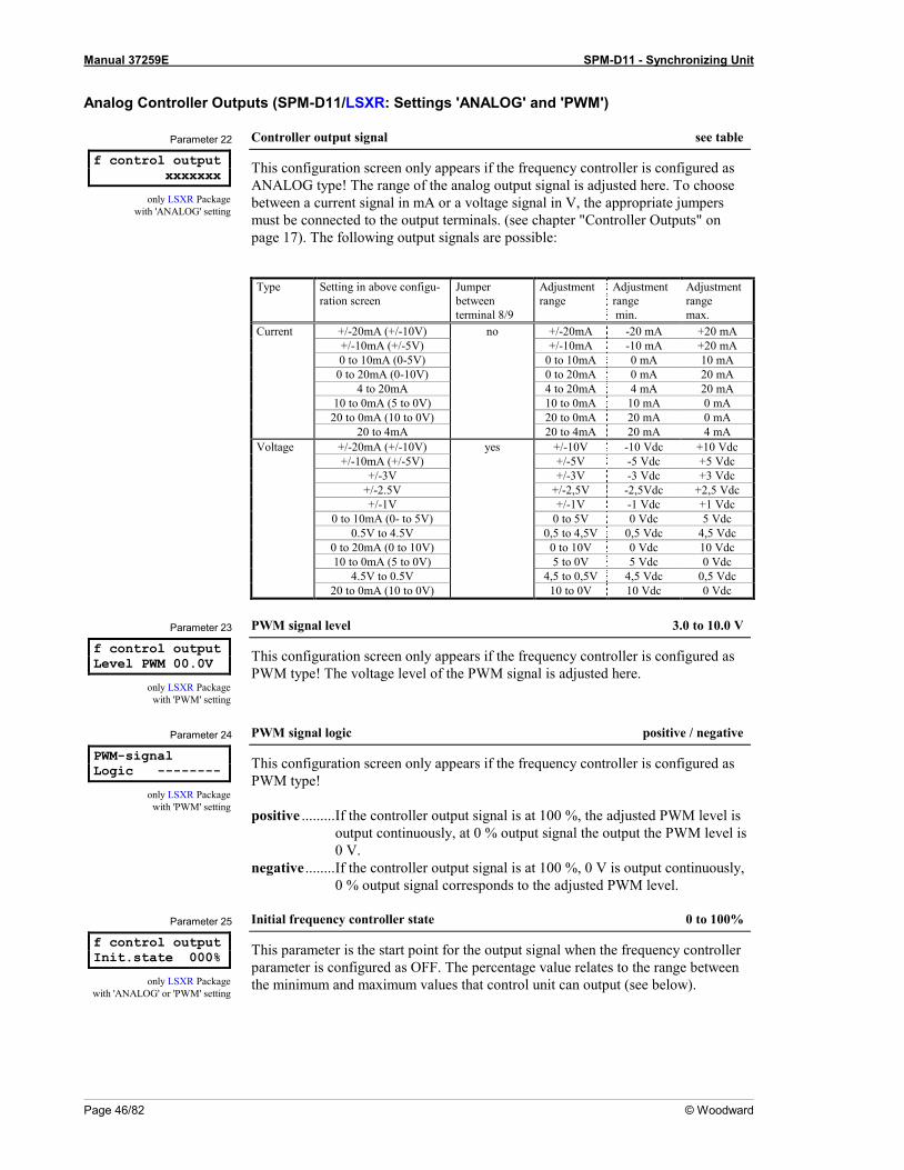
Manual 37259E SPM-D11 - Synchronizing Unit
Page 46/82 © Woodward
Analog Controller Outputs (SPM-D11/LSXR: Settings 'ANALOG' and 'PWM')
Parameter 22
f control output xxxxxxx
only LSXR Package with 'ANALOG' setting
Controller output signal see table
This configuration screen only appears if the frequency controller is configured as ANALOG type! The range of the analog output signal is adjusted here. To choose between a current signal in mA or a voltage signal in V, the appropriate jumpers must be connected to the output terminals. (see chapter "Controller Outputs" on page 17). The following output signals are possible: Type Setting in above configu-
ration screen Jumper between terminal 8/9
Adjustment range
Adjustment range min.
Adjustment range max.
Current +/-20mA (+/-10V) no +/-20mA -20 mA +20 mA +/-10mA (+/-5V) +/-10mA -10 mA +20 mA 0 to 10mA (0-5V) 0 to 10mA 0 mA 10 mA 0 to 20mA (0-10V) 0 to 20mA 0 mA 20 mA 4 to 20mA 4 to 20mA 4 mA 20 mA 10 to 0mA (5 to 0V) 10 to 0mA 10 mA 0 mA 20 to 0mA (10 to 0V) 20 to 0mA 20 mA 0 mA 20 to 4mA 20 to 4mA 20 mA 4 mA Voltage +/-20mA (+/-10V) yes +/-10V -10 Vdc +10 Vdc +/-10mA (+/-5V) +/-5V -5 Vdc +5 Vdc +/-3V +/-3V -3 Vdc +3 Vdc +/-2.5V +/-2,5V -2,5Vdc +2,5 Vdc +/-1V +/-1V -1 Vdc +1 Vdc 0 to 10mA (0- to 5V) 0 to 5V 0 Vdc 5 Vdc 0.5V to 4.5V 0,5 to 4,5V 0,5 Vdc 4,5 Vdc 0 to 20mA (0 to 10V) 0 to 10V 0 Vdc 10 Vdc 10 to 0mA (5 to 0V) 5 to 0V 5 Vdc 0 Vdc 4.5V to 0.5V 4,5 to 0,5V 4,5 Vdc 0,5 Vdc 20 to 0mA (10 to 0V) 10 to 0V 10 Vdc 0 Vdc
Parameter 23
f control output Level PWM 00.0V
only LSXR Package with 'PWM' setting
PWM signal level 3.0 to 10.0 V
This configuration screen only appears if the frequency controller is configured as PWM type! The voltage level of the PWM signal is adjusted here.
Parameter 24
PWM-signal Logic --------
only LSXR Package with 'PWM' setting
PWM signal logic positive / negative
This configuration screen only appears if the frequency controller is configured as PWM type! positive ......... If the controller output signal is at 100 %, the adjusted PWM level is
output continuously, at 0 % output signal the output the PWM level is 0 V.
negative ........ If the controller output signal is at 100 %, 0 V is output continuously, 0 % output signal corresponds to the adjusted PWM level.
Parameter 25
f control output Init.state 000%
only LSXR Package with 'ANALOG' or 'PWM' setting
Initial frequency controller state 0 to 100%
This parameter is the start point for the output signal when the frequency controller parameter is configured as OFF. The percentage value relates to the range between the minimum and maximum values that control unit can output (see below).

Manual 37259E SPM-D11 - Synchronizing Unit
© Woodward Page 47/82
Parameter 26
Freq. controller ON
LSXR Package with 'ANALOG' or 'PWM' setting
Frequency controller ON/OFF
ON ................ The generator frequency is controlled. The generator frequency is controlled in various manners depending on the task (no load / iso-lated operation / synchronization). The following screens of this func-tion are displayed.
OFF .............. Control is not carried out and the following screens of this function are not displayed.
Parameter 27
Freq. controller Isol. oper. ON
LSXR Package with 'ANALOG' or 'PWM' setting
Frequency controller – isolated operation ON/OFF
The setting of this screen has no influence on the load share control. ON ................ In isolated operation the frequency controller is enabled. OFF .............. In isolated operation the frequency controller is disabled.
Parameter 28
Freq. controller Ramp 00.0Hz/s
LSXR Package with 'ANALOG' or 'PWM' setting
Frequency controller set point ramp 0.1 to 99.9 Hz/s
A change in set point is supplied to the controller via a ramp. The slope of the ramp is used to alter the rate at which the controller follows the set point value. The more rapidly the set point should change, the greater this setting should be.
Parameter 29
f control output (max.) 000%
only LSXR Package with 'ANALOG' or 'PWM' setting
Maximum value frequency controller 0 to 100%
Upper limit of the analog controller output.
Parameter 30
f control output (min.) 000%
only LSXR Package with 'ANALOG' or 'PWM' setting
Minimum value frequency controller 0 to 100%
Lower limit of the analog controller output.
Parameter 31
Freq. controller Gain Kp 000
only LSXR Package with 'ANALOG' or 'PWM' setting
P gain of the frequency controller 1 to 240
The proportional-action coefficient KP indicates the closed-loop control system gain. By increasing the gain, the response is increased to permit larger corrections to the variable to be controlled. The optimum setting depends on the behavior of the system. If the gain is too low, the control action becomes slow. If the gain is confi-gured too high, the result is excessive overshoot/undershoot of the desired value. Refer to "Analog Controller Outputs" on page 30.
Parameter 32
Freq. controller Reset Tn 00.0s
only LSXR Package with 'ANALOG' or 'PWM' setting
Reset time frequency controller 0.0 to 60.0 s
The reset time Tn represents the I-component of the PID controller. The reset time corrects for any offset (between set point and process variable) over time until the process variable and the set point are the same. This parameter defines how quickly the reset attempts to correct for any offset. If Tn is configured as 0.00 s, the I-component of the PID loop is disabled. Refer to "Analog Controller Outputs" on page 30.

Manual 37259E SPM-D11 - Synchronizing Unit
Page 48/82 © Woodward
Parameter 33
Freq. controller Derivat.Tv 0.00s
only LSXR Package with 'ANALOG' or 'PWM' setting
Derivative-action time frequency controller 0.00 to 6.00 s
The derivative-action time TV represents the D-component of the PID controller. The D-component of the controller output becomes effective with large variations of the offset, e.g. in case of load-shedding. The lower the derivative-action time is configured, the higher the controller reaction is. If TV is configured as 0.00 s, the D-component of the PID loop is disabled. Refer to "Analog Controller Outputs" on page 30.
Voltage Controller The SPM-D11/LSR is provided with a three-step controller for voltages and does not contain the following screen. Moreover, only the screens for setting the three-step controller exist. Several controller output signals can be selected using the following screen with the SPM-D11/LSRX. Depending on the selected controller type, the following screens belonging to it appear.
Parameter 34
V contr. type xxxxxxx
LSRX Package only
Voltage controller type THREESTEP/ANALOG
THREESTEP: The voltage controller operates as three-step controller and issues raise (V+) and lower (V-) pulses via the respective relays. Only one of the two controllers (the frequency or the voltage controller) can be used for relay output at a time.
ANALOG ..... The voltage controller operates as continuous controller with an ana-log output signal (mA or V).
Note: The controller setting and the following screens are different, depending on the controller type selected here.
Three-Position Controller (SPM-D11/LSR and SPM-D11/LSXR: Setting 'THREESTEP')
Parameter 35
Volt. controller ON
LSXR Package: setting 'THREESTEP'
Voltage controller ON/OFF
ON ................ Generator voltage control is carried out. The generator voltage is con-trolled in various manners depending on the task (no load / isolated operation / synchronization). The following screens of this function are displayed.
OFF .............. Control is not carried out, and the following screens of this function are not displayed.
Parameter 36
Volt. controller Isol. oper. ON
LSXR Package: setting 'THREESTEP'
Voltage controller isolated mode ON/OFF
The setting of this screen has no influence on the load share control. ON ................ In isolated operation the voltage controller is enabled. OFF .............. In isolated operation the voltage controller is disabled.
Parameter 37
Volt. controller Ramp = 00V/s
LSXR Package: setting 'THREESTEP'
Voltage controller set point ramp 1 to 99 V/s
A change in set point is supplied to the controller via a ramp. The slope of the ramp is used to alter the rate at which the controller follows the set point value. The more rapidly the set point should change, the greater should be the value set here.

Manual 37259E SPM-D11 - Synchronizing Unit
© Woodward Page 49/82
Parameter 38
Volt. controller Dead band= 00,0V
LSXR Package: setting 'THREESTEP' only
Voltage controller insensitivity [1] 0.1 to 15.V, [4] 0.5 to 60.0 V
No load/Isolated operation: The measured generator voltage is controlled so that it does not deviate from the configured voltage by more than the value configured in this dead band setting while operating in a steady state.
Synchronization: The measured generator voltage is controlled so that the diffe-rential voltage does not exceed this dead band setting while operating in a steady state. The mains or busbar voltage is used as the set point value.
Parameter 39
Volt. controller Time pulse>000ms
LSXR Package: setting 'THREESTEP' only
Minimum voltage controller ON period 20 to 250 ms
The minimum ON period of the relay should be selected in such a manner that the downstream control element responds reliably to the pulse length that has been set here. The smallest possible time must be set in order to ensure optimum control be-havior.
Parameter 40
Volt. controller Gain Kp 00.0
LSXR Package: setting 'THREESTEP' only
Voltage controller gain factor 0.1 to 99.9
The gain factor Kp influences the ON time of the relays. The gain factor Kp influ-ences the ON time of the relays. By increasing the gain, the response is increased to permit larger corrections to the variable to be controlled resulting in longer ON time periods. The optimum setting depends on the behavior of the system. If the gain is too low, the control action becomes slow. If the gain is configured too high, the re-sult is excessive overshoot/undershoot of the desired value.
Analog Controller Outputs (SPM-D11/LSXR: Setting 'ANALOG')
Parameter 41
V control output -------
only LSXR Package with 'ANALOG' setting
Controller output signal see table
The range of the analog output signal is adjusted here. To choose between a current signal in mA or a voltage signal in V, the appropriate jumpers must be connected to the output terminals. (see chapter Relay Outputs on page 16). The following output signals are possible: Type Setting in above configu-
ration screen Jumper between terminal 11/12
Adjustment range
Adjustment range min.
Adjustment range max.
Current +/-20mA (+/-10V) no +/-20mA -20 mA +20 mA +/-10mA (+/-5V) +/-10mA -10 mA +10 mA 0 to 10mA (0 to 5V) 0 to 10mA 0 mA 10 mA 0 to 20mA (0 to 10V) 0 to 20mA 0 mA 20 mA 4 to 20mA 4 to 20mA 4 mA 20 mA 10 to 0mA (5 to 0V) 10 to 0mA 10 mA 0 mA 20 to 0mA (10 to 0V) 20 to -0mA 20 mA 0 mA 20 to 4mA 20 to 4mA 20 mA 4 mA Voltage +/-20mA (+/-10V) yes +/-10V -10 Vdc +10 Vdc +/-10mA (+/-5V) +/-5V -5 Vdc +5 Vdc +/-3V +/-3V -3 Vdc +3 Vdc +/-2.5V +/-2,5V -2,5Vdc +2,5 Vdc +/-1V +/-1V -1 Vdc +1 Vdc 0 to 10mA (0 to 5V) 0-5V 0 Vdc 5 Vdc 0.5V to 4.5V 0,5 to 4,5V 0,5 Vdc 4,5 Vdc 0 to 20mA (0 to 10V) 0 to 10V 0 Vdc 10 Vdc 10 to 0mA (5 to 0V) 5 to 0V 5 Vdc 0 Vdc 4.5V to -0.5V 4,5 to 0,5V 4,5 Vdc 0,5 Vdc 20 to 0mA (10 to 0V) 10 to 0V 10 Vdc 0 Vdc

Manual 37259E SPM-D11 - Synchronizing Unit
Page 50/82 © Woodward
Parameter 42
V control output Init.state 000%
only LSXR Package with 'ANALOG' setting
Voltage controller - initial state 0 to 100%
This parameter is the start point for the output signal when the frequency controller parameter is configured as OFF. The percentage value relates to the range between the minimum and maximum values that control unit can output (see below).
Parameter 43
Volt. controller ON
LSXR Package with 'ANALOG' setting
Voltage controller ON/OFF
ON ................ Generator voltage control is carried out. The generator voltage is con-trolled in various manners depending on the task (no load / isolated operation / synchronization). The following screens of this function are displayed.
OFF .............. Control is not carried out, and the following screens of this function are not displayed.
Parameter 44
Volt. controller Isol. oper. ON
LSXR Package with 'ANALOG' setting
Voltage controller isolated mode ON/OFF
The setting of this screen has no influence on the load share control. ON ................ In isolated operation the voltage controller is enabled. OFF .............. In isolated operation the voltage controller is disabled.
Parameter 45
Volt. Controller Ramp = 00V/s
LSXR Package with 'ANALOG' setting
Voltage controller set point ramp 1 to 99 V/s
A change in set point is supplied to the controller via a ramp. The slope of the ramp is used to alter the rate at which the controller follows the set point value. The more rapidly the set point should change, the greater should be the value set here.
Parameter 46
V control output (max.) 000%
only LSXR Package with 'ANALOG' setting
Voltage controller maximum output 0 to 100 %
Upper limit of the analog controller output.
Parameter 47
V control output (min.) 000%
only LSXR Package with 'ANALOG' setting
Voltage controller minimum output 0 to 100 %
Lower limit of the analog controller output.
Parameter 48
Volt. controller Gain Kp 000
only LSXR Package with 'ANALOG' setting
Voltage controller P-gain 1 to 240
The proportional-action coefficient KP indicates the closed-loop control system gain. By increasing the gain, the response is increased to permit larger corrections to the variable to be controlled. The optimum setting depends on the behavior of the system. If the gain is too low, the control action becomes slow. If the gain is confi-gured too high, the result is excessive overshoot/undershoot of the desired value. Refer to "Analog Controller Outputs" on page 30.
Parameter 49
Volt. controller Reset Tn 00.0s
only LSXR Package with 'ANALOG' setting
Voltage controller reset time 0.0 to 60.0 s
The reset time Tn represents the I-component of the PID controller. The reset time corrects for any offset (between set point and process variable) over time until the process variable and the set point are the same. This parameter defines how quickly the reset attempts to correct for any offset. If Tn is configured as 0.00 s, the I-component of the PID loop is disabled. Refer to "Analog Controller Outputs" on page 30.

Manual 37259E SPM-D11 - Synchronizing Unit
© Woodward Page 51/82
Parameter 50
Volt. controller Derivat.Tv=0.00s
only LSXR Package with 'ANALOG' setting
Voltage controller - derivative-action time 0.00 to 6.00 s
The derivative-action time TV represents the D-component of the PID controller. The D-component of the controller output becomes effective with large variations of the offset, e.g. in case of load-shedding. The lower the derivative-action time is configured, the higher the controller reaction is. If TV is configured as 0.00 s, the D-component of the PID loop is disabled. Refer to "Analog Controller Outputs" on page 30.
Power Factor Control
NOTE Refer to the appendix Power Factor Definition on page 75 for this.
Parameter 51
Pow.fact.control ON
Power factor controller ON/OFF
ON ................ A load-independent control of the power ϕ factor is carried out during mains/parallel operation. The power factor cannot be measured accu-rately and the controller is automatically locked to prevent instability when small currents (less than 5 % of the CT secondary rated current) are detected. The following screen masks of this option will be dis-played.
OFF .............. The frequency is not controlled, and the following screens of this op-tion will not be displayed.
Parameter 52
Pow.fact.control Set point = 0.00
Power factor controller set point i0.70 to 1.00 to c0.70
While operating in a mains/parallel operation, the reactive load is controlled so that this preset power factor is maintained when the generator is in a steady state. The letters "i" stands for "inductive = lagging" (overexcited generator) and "c" for "ca-pacitive = leading" (underexcited generator) reactive load. This parameter is only enabled when operating in mains/parallel.
Parameter 53
Pow.fact.control Ramp 0.00/s
Set point ramp of the power factor controller 0.01 to 0.30 /s
The set point ramp determines how fast the power factor set point approaches its target value. The slope of the ramp is linear.

Manual 37259E SPM-D11 - Synchronizing Unit
Page 52/82 © Woodward
NOTE Refer to the parameter settings for the voltage controller under Voltage Controller starting on page 48. The parameter settings performed for the voltage controller may be applied to the power factor con-troller as well.
Three-Position Controller (SPM-D11/LSR and SPM-D11/LSXR: Setting 'THREESTEP')
Parameter 54
Pow.fact.control Dead band 00.0%
LSXR Package: setting 'THREESTEP' only
Power factor controller insensitivity 0.5 to 25.0 %
The control automatically calculates the amount of reactive load which corresponds to the power factor set point. In mains/parallel operation, the reactive load is controlled so that it does not deviate from the configured power factor set point by more than the value configured in this dead band (%) setting while operating in a steady state. The percentage value refers to the generator nominal power.
Parameter 55
Pow.fact.control Gain Kp=00.0
LSXR Package: setting 'THREESTEP' only
Power factor controller gain 0.1 to 99.9
The gain factor Kp influences the ON time of the relays. By increasing the gain, the response is increased to permit larger corrections to the variable to be controlled re-sulting in longer ON time periods. The optimum setting depends on the behavior of the system. If the gain is too low, the control action becomes slow. If the gain is configured too high, the result is excessive overshoot/undershoot of the desired val-ue.
Analog Controller (SPM-D11/LSXR: Setting 'ANALOG')
Parameter 56
Pow.fact.control Gain Kp 000
only LSXR Package with 'ANALOG' setting
Power factor controller gain 1 to 240
The proportional-action coefficient KP indicates the closed-loop control system gain. By increasing the gain, the response is increased to permit larger corrections to the variable to be controlled. The optimum setting depends on the behavior of the system. If the gain is too low, the control action becomes slow. If the gain is confi-gured too high, the result is excessive overshoot/undershoot of the desired value. Refer to "Analog Controller Outputs" on page 30.
Parameter 57
Pow.fact.control Reset Tn 00.0s
only LSXR Package with 'ANALOG' setting
Power factor controller reset time 0.0 to 60.0 s
The reset time Tn represents the I-component of the PID controller. The reset time corrects for any offset (between set point and process variable) over time until the process variable and the set point are the same. This parameter defines how quickly the reset attempts to correct for any offset. If Tn is configured as 0.00 s, the I-component of the PID loop is disabled. Refer to "Analog Controller Outputs" on page 30.
Parameter 58
Pow.fact.control Derivat.Tv 0.00s
only LSXR Package with 'ANALOG' setting
Power factor controller – derivative action time 0.00 to 6.00 s
The derivative-action time TV represents the D-component of the PID controller. The D-component of the controller output becomes effective with large variations of the offset, e.g. in case of load-shedding. The lower the derivative-action time is configured, the higher the controller reaction is. If TV is configured as 0.00 s, the D-component of the PID loop is disabled. Refer to "Analog Controller Outputs" on page 30.

Manual 37259E SPM-D11 - Synchronizing Unit
© Woodward Page 53/82
Real Power Controller
Parameter 59
Power controller ON
Real power controller ON/OFF
ON ................ During mains/parallel operation the real power is controlled to the pre-selected set point value. The following screens of this option are displayed.
OFF .............. The power is not controlled, and the following screens of this option not displayed.
Power Limitation
Parameter 60
Power controller P max.= 000 %
Maximum power limitation (maximum demand) 10 to 120 %
If limiting control of the generator maximum real power is required, a value in per-cent referring to the generator rated power is set in this screen. The value "Pmax" limits only the set value of the real power controller and has no function in isolated operation.
Parameter 61
Power controller P min.= 000 %
Minimum power limitation (minimum power) 0 to 50 %
If limiting control of the generator minimum real power is required, a value in per-cent referring to the generator rated power is set in this screen. The value "Pmin" limits only the set value of the real power controller and has no function in isolated operation.
Part Load Lead
Parameter 62
Warm up load Set point = 000%
Limit value partial load 5 to 110 %
If the engine requires a warming-up period a lower fixed power set point value can be specified. The limit value of partial load refers to the generator rated power.
Parameter 63
Warm up load time 000s
Period of partial load limit 0 to 600 s
If a warm up load set point value has been selected, the time period for this warm up is configured in this parameter. The time period for the partial load imitates at the closing of the generator circuit breaker. If a warm up period is not desired, enter "0" for this parameter.
Shut Down
Parameter 64
Download and open GCB ON
Shut down ON / OFF
ON ................ The generator set will shut down if the input "enable GCB" is re-moved. Refer to the Shutdown section on page 27 for more informa-tion).
OFF .............. If "enable GCB" is removed, the CB will not be opened in isolated operation. In parallel isolated operation the generator CB remains closed.

Manual 37259E SPM-D11 - Synchronizing Unit
Page 54/82 © Woodward
Power Set point Value
NOTE The SPM-D11 does not take the connection to the utility into consideration. This means that if the plant generates excess power, power will be exported to the utility. If the plant does not generate enough power to meet demand, then power will be imported from the utility. This power controller does not perform process control.
Parameter 65
Power controller P set1 = 0000kW
Set value 1 Real power controller 0 to 9,999 kW
Setting of the internal power set value 1( Pset 1). If this set point is selected, this is the reference value for controlling the real power.
Parameter 66
Power controller P set2 = 0000kW
Set value 2 Real power controller 0 to 9,999 kW
Setting of the internal power set value 2 (Pset2). If this set point is selected, this is the reference value for controlling the real power.
Parameter 67
Power set point External ON
External set value ON/OFF
Selection of the external power set point. If this set point is selected, the real power is controlled to the external power set reference value.
Parameter 68
Analog input 0..00mA
External set point value: Range 0 to 20 / 4 to 20 mA
The analog reference signal input of the real power controller can be switched be-tween 0 to 20 mA and 4 to 20 mA depending on the remote set point signal. 0 to 20 mA .... Minimum value of the set point value: 0 mA; Maximum value:
20 mA. 4 to 20 mA .... Minimum value of the set point value: 4 mA; Maximum value:
20 mA. Wire break monitoring is performed.
Parameter 69
External setp. 0mA 0000kW
Scaling the minimum value 0 to 8,000 kW
The minimum value of the real power set point is defined here.
Parameter 70
External setp. 20mA 0000kW
Scaling the maximum value 0 to 8.000 kW
The maximum value of the real power set point is defined here.
Parameter 71
External setp. Value = 000kW
Display of the current set point value 0 to 8,000 kW
This screen is not used to enter a value, but to display the current measured value, calculated into kW, of the analog input. This permits the mA signal to be validated even if the engine is stopped.
Parameter 72
Power controller Ramp 000 kW/s
Real power controller set point ramp 1 to 999 kW/s
A change in set point is supplied to the controller via a ramp. The slope of the ramp is used to alter the rate at which the controller follows the set point value. The more rapidly the set point should change, the greater should be the value set here. This ramp will also be used to reduce the power with a Shutdown (refer to page 27).

Manual 37259E SPM-D11 - Synchronizing Unit
© Woodward Page 55/82
Three-Position Controller (SPM-D11/LSR and SPM-D11/LSXR: Setting 'THREESTEP')
Parameter 73
Power controller Dead band= 00.0%
LSXR Package: setting 'THREESTEP' only
Real power controller insensitivity 0.1 to 25.0 %
In mains/parallel operation the real power will be controlled so that it does not de-viate from the configured power factor set point by more than the value configured in this dead band (%) setting while operating in a steady state. This percentage is based on the generator nominal power.
Parameter 74
Power controller Gain Kp 00.0
LSXR Package: setting 'THREESTEP' only
Gain of real load controller 0.1 to 99.9
The gain factor Kp influences the ON time of the relays. By increasing the gain, the response is increased to permit larger corrections to the variable to be controlled re-sulting in longer ON time periods. The optimum setting depends on the behavior of the system. If the gain is too low, the control action becomes slow. If the gain is configured too high, the result is excessive overshoot/undershoot of the desired val-ue.
Parameter 75
Power controller Sens.red. *0.0
LSXR Package: setting 'THREESTEP' only
Sensitivity reduction of real power controller 1.0 to 9.9
If the controller does not issue an actuating pulse at least 5 seconds after reaching steady state condition, the sensitivity will be reduced by the entered factor. Example: In case of a dead band of 2.5 % and a factor 2.0 the dead band will be increased to 5.0 % after 5 seconds. If the system deviation afterwards exceeds 5.0 %, the original dead band (2.5 %) of the con-troller will be set automatically. Using this entry, frequent unnecessary actuation processes can be avoided, thus extending the life of the actuating device.
Analog controller (SPM-D11/LSXR: Setting 'ANALOG' & 'PWM')
Parameter 76
Power controller Gain Kp 000
only LSXR Package with 'ANALOG' or 'PWM' setting
P gain of the real power controller 1 to 240
The proportional-action coefficient KP indicates the closed-loop control system gain. By increasing the gain, the response is increased to permit larger corrections to the variable to be controlled. The optimum setting depends on the behavior of the system. If the gain is too low, the control action becomes slow. If the gain is confi-gured too high, the result is excessive overshoot/undershoot of the desired value. Refer to "Analog Controller Outputs" on page 30.
Parameter 77
Power controller Reset Tn 00.0s
only LSXR Package with 'ANALOG' or 'PWM' setting
Reset time of the active load controller 0.0 to 60.0 s
The reset time Tn represents the I-component of the PID controller. The reset time corrects for any offset (between set point and process variable) over time until the process variable and the set point are the same. This parameter defines how quickly the reset attempts to correct for any offset. If Tn is configured as 0.00 s, the I-component of the PID loop is disabled. Refer to "Analog Controller Outputs" on page 30.
Parameter 78
Power controller Derivat.Tv 0.00s
only LSXR Package with 'ANALOG' or 'PWM' setting
Derivative action time of the active load controller 0,00 to 6,00 s
The derivative-action time TV represents the D-component of the PID controller. The D-component of the controller output becomes effective with large variations of the offset, e.g. in case of load-shedding. The lower the derivative-action time is configured, the higher the controller reaction is. If TV is configured as 0.00 s, the D-component of the PID loop is disabled. Refer to "Analog Controller Outputs" on page 30.

Manual 37259E SPM-D11 - Synchronizing Unit
Page 56/82 © Woodward
Power Limit
The generator power is monitored for exceeding the configured threshold value. The excess is signaled with the relay "Power limit". As long as the power is below the threshold value, the relay is energized (the contact is closed). If the power has exceeded the threshold value for at least the configured delay, the relay contact will be opened. The relay contact will close, after the power is below the threshold value minus the configured hysteresis for at least a fixed delay of 1 second. Using this relay and external circuits it is possible to disconnect loads or ac-tivate further generators.
NOTE This watchdog is not part of the generator protection functions. No message is displayed when the watchdog is triggered, only a relay is energized. The overload protection is intended for a generator that has been configured for equivalent operations (see page 63).
Parameter 79
Gen.active-power Monitoring ON
Generator power monitoring ON/OFF
ON ................ The generator real power is monitored. The following screens of this option are displayed.
OFF .............. There is no active power monitoring performed and the following screens of this option are not displayed.
Parameter 80
Power monitoring Threshold =000%
Generator power monitoring threshold 0 to 150 %
The threshold relates to the rated power of the generator.
Parameter 81
Power monitoring Hysteresis =000%
Generator power monitoring hysteresis 0 to 100 %
The hysteresis relates to the rated power of the generator. This value is how much below the threshold limit that the monitored power must drop for the controller to terminate the power threshold limit surpassed operations.
Parameter 82
Power monitoring Delay time =000%
Generator power monitoring delay 0 to 600 s
To open the relay contact, the threshold hast to be exceeded continuously for the time configured here.

Manual 37259E SPM-D11 - Synchronizing Unit
© Woodward Page 57/82
Load/Var Sharing
Parameter 83
Active power Load-share ON
Load sharing ON/OFF
ON ................ Real power is distributed among the generators operating in parallel. The generator outputs are distributed depending on the set values. The following screens of this function are displayed
OFF .............. There is no load sharing control performed, and the following screens of this function are not displayed.
Parameter 84
Act. load share Factor =00%
Load sharing reference variable 10 to 99 %
The higher the weighing factor is configured, the more influence the main control variable (frequency) has on the control. The lower the weighing factor is confi-gured, the greater the influence of the secondary control variable (generator real power).
The value of the analog signal depends on the measured real power in relation to the rated power. Therefore, there is the following relation between real power and analog signal:
0 to 4 V of the analog signal corresponds with 0 to 100 % of the rated power Example for a rated power of 400 kW:
Currently measured power Analog signal 100 kW 1 V 200 kW 2 V 400 kW 4 V
Parameter 85
Reactive power Load-share ON
var sharing ON/OFF
ON ................ Re-active power is distributed among the several generators operating in parallel. The generator outputs are distributed depending on the set values. The following screens of this function are displayed:
OFF .............. There is no var sharing control performed, and the following screens of this function are not displayed.
Parameter 86
React.load share Factor =00%
var sharing reference variable 10 to 99 %
The higher the weighing factor is configured, the more influence the main control variable (voltage) has on the control. The lower the weighing factor is configured, the greater the influence of the secondary control variable (generator reactive pow-er).
The value of the analog signal depends on the measured reactive power in relation to the rated power. Therefore, there is the following relation between reactive power and analog signal:
0 to 5V of the analog signal corresponds with 85% of the capacitive rated power to 85% of the inductive rated power
Example for a rated power of 400 kW:
Actual reactive power (without display) Analog signal -340 kW 0 V 85% of the rated power
capacitive = negative reactive power 0 kW 2.5V 0% of the rated power
no reactive power +340 kW 5 V 85% of the rated power
inductive = positive reactive power

Manual 37259E SPM-D11 - Synchronizing Unit
Page 58/82 © Woodward
Synchronization ≡≡≡≡≡≡≡≡≡≡≡≡≡≡≡≡≡≡≡≡≡≡≡≡≡
Configure Synchronization
CAUTION Please consider that the unit does not have an internal rotating field monitoring. The unit assumes always a clockwise phase rotation direction of all voltage systems, which are meas-ured. A rotating field monitoring must be provided by the customer in order to avoid a CB closure with a counter-clockwise rotating field.
Parameter 87
Synchronizing functions ON
Synchronization functions ON/OFF
ON ................ Frequency and voltage matching for the generator and busbar is per-formed and a close command is issued. The subsequent screens of this function are displayed.
OFF .............. No synchronization occurs, but no-load control functions are per-formed if necessary. No close command is issued. The subsequent screens of this function are not displayed.
Parameter 88
Synchronization df max = 0.00Hz
Max. permissible differential frequency (positive slip) 0.02 to 0.49 Hz
The prerequisite for initiating a close command that the differential frequency must be lower than the value configured here. This value specifies the upper frequency limit. A positive value indicates that the generator frequency is greater than the bus-bar frequency.
Parameter 89
Synchronization df min =-0.00Hz
Max. permissible differential frequency (negative slip) 0.00 to 0.49 Hz
The prerequisite for initiating a close command that the differential frequency must be higher than the value configured here. This value specifies the lower frequency limit. A negative value indicates that the generator frequency is less than the busbar frequency.
Parameter 90
Synchronization dV max = 00V
Max. permissible differential voltage [1] 1 to 20 V, [4] 1 to 60 V
A close command will not be issued until the measured differential voltage of the generator and busbar falls below the value configured here.
Parameter 91
Synchronization Brk.hold T>0.00s
Minimum pulse period of close relay 0.04 to 0.50 s
The length of the close command pulse can be adjusted to the requirement of the subordinate switching circuit.

Manual 37259E SPM-D11 - Synchronizing Unit
© Woodward Page 59/82
Parameter 92
Phase matching ON
Phase matching control ON/OFF
ON ................ The synchronization is performed with phase matching control and the power circuit breaker closure is dependent upon the phase angle (refer to "Phase Matching Synchronization" on page 25). Only the pa-rameters relating to phase matching are displayed.
OFF .............. Synchronization is performed when the frequency and voltage diffe-rential are within the specified ranges. The circuit breaker is closed at the synchronous point (refer to "Synchronization with slip" on page 25). Only the parameters relating to slip synchronization are displayed.
Parameter 93
Slip synchroniz. Max phase < 00°
Phase matching control = OFF
Max. perm. differential angle in case of phase-angle-zero-control 0 to 60°
This configuration screen is displayed only if the phase matching control is dis-abled! A connect command is only issued when the phase angle differential is less than the value configured in this screen. Synchronization with slip - When operating in the "slip synchronization" mode this phase angle may be set as the maximum value that a close breaker command may be issued. This is determined by the formula:
Δφ = TClose * 360° * Δf
Example: If the frequency difference is 0.5Hz and the delay of the circuit breaker delay is 80ms the delta phi is determined as follows:
TClose = 80ms, Δf= 0.5Hz => Δφ = 0.08s*360*0.5 = 14.4° As an example if the desired synchronization window is to be limited to a maximum of 10°, then the limit value of 10° would be entered here. If this parameter is not re-quired, then the angle must be configured as 60° Synch-check - In the operation mode "Synch-check" the phase angle differential must be less than the value configured here for the relay "Command: close CB" to be energized.
Parameter 94
Slip synchroniz. TClose GCB=000ms
Phase matching control = OFF
Inherent delay of CB 40 to 300 ms
This configuration screen is displayed only if the phase matching control is dis-abled! All circuit breakers have an inherent delay from the time the close command is issued until the circuit breaker contacts are closed. That time is configured in this screen. This permits the controller to issue the breaker closure command with enough lead-time so that the breaker contacts close at the synchronous point.
Parameter 95
Phase matching Max phase < 00°
Phase matching control = ON
Max. permissible differential angle 0 to 60°
This configuration screen is displayed only if the phase matching control is enabled! A connect command is only issued when the phase angle differential is less than the value configured in this screen.
Parameter 96
Phase matching Dwell time 00.0s
Phase matching control = ON
Phase matching control breaker transition dwell time 0.2 to 10.0 s
This configuration screen is displayed only if the phase matching control is enabled! Once the controller detects that the phase angle matching has been achieved, a timer is started. Only after the expiration of this dwell time is the connect command is-sued. If the controller detects that one of the synchronization parameters has left the required range, the dwell timer is reset.
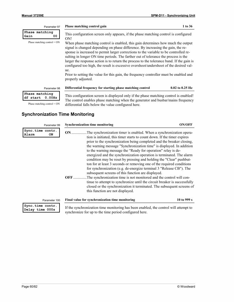
Manual 37259E SPM-D11 - Synchronizing Unit
Page 60/82 © Woodward
Parameter 97
Phase matching Gain 00
Phase matching control = ON
Phase matching control gain 1 to 36
This configuration screen only appears, if the phase matching control is configured ON! When phase matching control is enabled, this gain determines how much the output signal is changed depending on phase difference. By increasing the gain, the re-sponse is increased to permit larger corrections to the variable to be controlled re-sulting in longer ON time periods. The farther out of tolerance the process is the larger the response action is to return the process to the tolerance band. If the gain is configured too high, the result is excessive overshoot/undershoot of the desired val-ue. Prior to setting the value for this gain, the frequency controller must be enabled and properly adjusted.
Parameter 98
Phase matching df start 0.00Hz
Phase matching control = ON
Differential frequency for starting phase matching control 0.02 to 0.25 Hz
This configuration screen is displayed only if the phase matching control is enabled! The control enables phase matching when the generator and busbar/mains frequency differential falls below the value configured here.
Synchronization Time Monitoring
Parameter 99
Sync.time contr. Alarm ON
Synchronization time monitoring ON/OFF
ON ................ The synchronization timer is enabled. When a synchronization opera-tion is initiated, this timer starts to count down. If the timer expires prior to the synchronization being completed and the breaker closing, the warning message "Synchronization time" is displayed. In addition to the warning message the “Ready for operation" relay is de-energized and the synchronization operation is terminated. The alarm condition may be reset by pressing and holding the "Clear" pushbut-ton for at least 3 seconds or removing one of the required conditions for synchronization (e.g. de-energize terminal 3 "Release CB"). The subsequent screens of this function are displayed.
OFF .............. The synchronization time is not monitored and the control will con-tinue to attempt to synchronize until the circuit breaker is successfully closed or the synchronization it terminated. The subsequent screens of this function are not displayed.
Parameter 100
Sync.time contr. Delay time 000s
Final value for synchronization time monitoring 10 to 999 s
If the synchronization time monitoring has been enabled, the control will attempt to synchronize for up to the time period configured here.
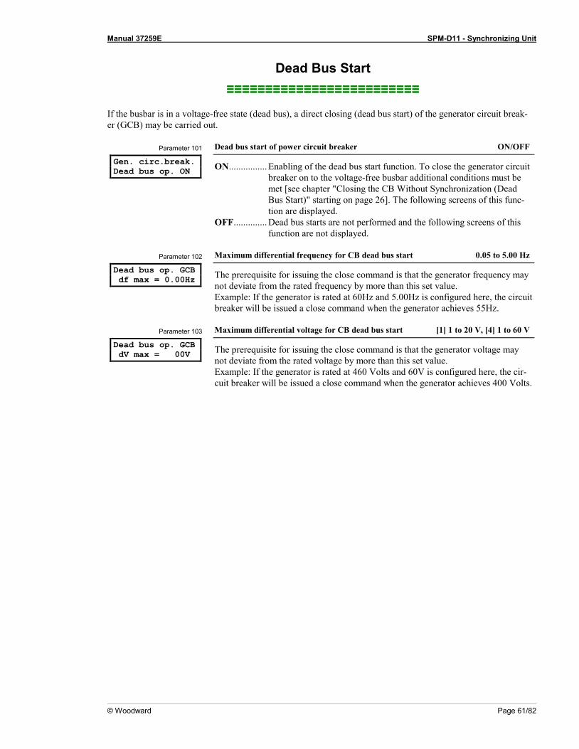
Manual 37259E SPM-D11 - Synchronizing Unit
© Woodward Page 61/82
Dead Bus Start ≡≡≡≡≡≡≡≡≡≡≡≡≡≡≡≡≡≡≡≡≡≡≡≡≡
If the busbar is in a voltage-free state (dead bus), a direct closing (dead bus start) of the generator circuit break-er (GCB) may be carried out.
Parameter 101
Gen. circ.break. Dead bus op. ON
Dead bus start of power circuit breaker ON/OFF
ON ................ Enabling of the dead bus start function. To close the generator circuit breaker on to the voltage-free busbar additional conditions must be met [see chapter "Closing the CB Without Synchronization (Dead Bus Start)" starting on page 26]. The following screens of this func-tion are displayed.
OFF .............. Dead bus starts are not performed and the following screens of this function are not displayed.
Parameter 102
Dead bus op. GCB df max = 0.00Hz
Maximum differential frequency for CB dead bus start 0.05 to 5.00 Hz
The prerequisite for issuing the close command is that the generator frequency may not deviate from the rated frequency by more than this set value. Example: If the generator is rated at 60Hz and 5.00Hz is configured here, the circuit breaker will be issued a close command when the generator achieves 55Hz.
Parameter 103
Dead bus op. GCB dV max = 00V
Maximum differential voltage for CB dead bus start [1] 1 to 20 V, [4] 1 to 60 V
The prerequisite for issuing the close command is that the generator voltage may not deviate from the rated voltage by more than this set value. Example: If the generator is rated at 460 Volts and 60V is configured here, the cir-cuit breaker will be issued a close command when the generator achieves 400 Volts.

Manual 37259E SPM-D11 - Synchronizing Unit
Page 62/82 © Woodward
Configure Monitoring ≡≡≡≡≡≡≡≡≡≡≡≡≡≡≡≡≡≡≡≡≡≡≡≡≡
Generator Reverse/Reduced Power Monitoring Generator real power is monitored to ensure it does not fall below a preset limit. The watchdog assigned to this relay is at terminals 37/38. The relay contact is a N.O. contact. When operating in normal operations the relay is continuously energized. If the monitored values leave the configured range, the relay will de-energize, the contact will open, and the message "Reverse/reduced power" will be displayed. If the fault conditions exist for less than 1 second, the relay returns to normal operations. The fault message on the display may be cleared automatically or by pressing the "Clear" button (see chapter Auto Acknowledge Messages at page 65).
Parameter 104
Reverse/min.pow. Monitoring ON
Reverse/reduced load monitoring ON/OFF
ON ................ Monitoring of reverse or reduced generator real power is performed. The following screens of this function are displayed.
OFF .............. There is no reverse or reduced power monitoring and the following screens of this function are not displayed
Parameter 105
Reverse/min.pow. Threshold = 00%
Reverse/reduced power monitoring threshold value -99 to 99 %
The threshold value refers to the configured rated power of the generator. Reduced power monitoring: A reduced power condition is detected if the meas-
ured real power drops below the (positive) limit value. Reverse power monitoring: A reverse power condition is detected if the measured
real power drops below the (negative) limit value. A reverse power condition can only be detected if the current is at least 2% of the CT’s rating. This must be considered when configuring the reverse power protec-tion.
Parameter 106
Reverse/min.pow. Delay 00.0s
Delay of reverse/reduced load monitoring 0.1 to 99.9 s
The generator real power must remain below the threshold value without interrup-tion for at least the period of time specified in this screen for a fault condition to be recognized.

Manual 37259E SPM-D11 - Synchronizing Unit
© Woodward Page 63/82
Generator Overload Monitoring Generator real power is monitored to ensure it does not exceed a preset limit. The watchdog assigned to this relay is at terminals 37/38. The relay contact is a N.O. contact. When operating in normal operations the relay is conti-nuously energized. If the monitored values leave the configured range, the relay will de-energize, the contact will open, and the message "Gen. overload" will be displayed. If the fault conditions exist for less than 1 second, the relay returns to normal operations. The fault message on the display may be cleared automatically or by pressing the ""Clear" button (see chapter Auto Acknowledge Messages at page 65).
Parameter 107
Gen. overload Monitoring ON
Overload monitoring ON / OFF
ON ................ Monitoring of generator real power for overload is performed. The following screens of this function are displayed.
OFF .............. There is no real power overload monitoring and the following screens of this function are not displayed.
Parameter 108
Gen. overload Threshold =000%
Generator overload threshold 0 to 150 %
The threshold value refers to the configured generator rated power.
Parameter 109
Gen. overload Delay time = 00s
Generator overload monitoring delay 0 to 99 s
The generator real power must remain above the threshold value without interrup-tion for at least the period of time specified in this screen for a fault condition to be recognized. If 0 seconds if configured here, the delay time is approximately 80ms.

Manual 37259E SPM-D11 - Synchronizing Unit
Page 64/82 © Woodward
Generator Frequency Monitoring Generator frequency is monitored to ensure it does not exceed or fall below the threshold value. The watchdog as-signed to this relay is at terminals 43/44. The relay contact is a N.O. contact. When operating in normal opera-tions the relay is continuously energized. If the monitored values leave the configured range, the relay will de-energize, the contact will open, and the message "Gen. overfreq." or. "Gen. underfreq." will be displayed. If the fault conditions exist for less than 1 second, the relay returns to normal operations. The fault message on the dis-play may be cleared automatically or by pressing the "Clear" button (see chapter Auto Acknowledge Messages at page 65).
Parameter 110
Gen.frequency- Monitoring ON
Generator frequency monitoring ON/OFF
ON ................ Generator frequency monitoring is enabled. The generator frequency is monitored for overfrequency and underfrequency. The following screens of this function are displayed.
OFF .............. There is no frequency monitoring, and the following screens of this function are not displayed.
Parameter 111
Gen. overfreq. f > 00.00Hz
Threshold value: Generator overfrequency 40.0 to 70.0 Hz
If the value of the generator frequency exceeds the value set here, an overfrequency alarm is issued.
Parameter 112
Gen. overfreq. Delay time=0.00s
Generator overfrequency threshold delay 0.04 to 9.98 s
In order to initiate an overfrequency alarm, the measured frequency must exceed and remain above the configured threshold without interruption for at least the time specified in this screen.
Parameter 113
Gen. underfreq. f < 00,00Hz
Threshold value: Generator underfrequency 40.0 to 70.0 Hz
If the value of the generator frequency falls below the value set here, an underfre-quency alarm is issued.
Parameter 114
Gen. underfreq. Delay time=0.00s
Generator underfrequency threshold delay 0.04 to 9.98 s
In order to initiate an underfrequency alarm, the measured frequency must fall be-low and remain below the configured threshold without interruption for at least the time specified in this screen.

Manual 37259E SPM-D11 - Synchronizing Unit
© Woodward Page 65/82
Generator Voltage Monitoring The line voltages VL1/VL2 of the generator are monitored to ensure they do not exceed or fall below the threshold values. The watchdog assigned to this relay is at terminals 41/42. The relay contact is a N.O. contact. When oper-ating in normal operations the relay is continuously energized. If the monitored values leave the configured range, the relay will de-energize, the contact will open, and the message "Gen. overvoltage" or. "Gen. undervoltage" will be displayed. If the fault conditions exist for less than 1 second, the relay returns to normal operations. The fault message on the display may be cleared automatically or by pressing the "Clear" button (see chapter Auto Ac-knowledge Messages at page 65).
Parameter 115
Gen.voltage- Monitoring ON
Generator voltage monitoring ON / OFF
ON ................ The generator voltage monitoring is enabled. The generator voltage is monitored with regard to overvoltage and undervoltage. The follow-ing screens of this function are displayed.
OFF .............. No overvoltage or undervoltage monitoring is performed and the fol-lowing screens of this function are not displayed.
Parameter 116
Gen.overvoltage U > 000V
Threshold value: Gen. overvoltage [1] 20 to 150 V; [4] 20 to 520 V
If the value of the generator voltage exceeds the value set here, an overvoltage alarm is issued.
Parameter 117
Gen.overvoltage Delay time=0.00s
Generator overvoltage threshold delay 0.04 to 9.98 s
In order to initiate an overvoltage alarm, the measured voltage must exceed and re-main above the configured threshold without interruption for at least the time speci-fied in this screen.
Parameter 118
Gen.undervoltage U < 000V
Threshold value: Gen. undervoltage [1] 20 to 150 V; [4] 20 to 520 V
If the value of the generator voltage falls below the value set here, an undervoltage alarm is issued.
Parameter 119
Gen.undervoltage Delay time=0.00s
Generator undervoltage threshold delay 0,04 to 9,98 s
In order to initiate an undervoltage alarm, the measured voltage must fall below and remain below the configured threshold without interruption for at least the time spe-cified in this screen.
Auto Acknowledge Messages Parameter 120
Auto-acknowledge messages ON
Messages auto acknowledgment EIN/AUS
ON ................ When fault conditions are no longer detected and the clear message delay time has expired, the corresponding message is automatically deleted.
OFF .............. When fault conditions are no longer detected and the corresponding message continues to be displayed. Pressing the "Clear" button for at least 3 seconds will clear the fault message. The following screen is not displayed.
Parameter 121
Acknowledge Message aft. 00s
Clear messages delay 1 to 99 s
This screen only appears if the screen "Messages auto-acknowledgement" is set to ON. Clearing the messages occurs after the specified time.

Manual 37259E SPM-D11 - Synchronizing Unit
Page 66/82 © Woodward
Password Configuration ≡≡≡≡≡≡≡≡≡≡≡≡≡≡≡≡≡≡≡≡≡≡≡≡≡
NOTE Once the code level is entered, access to the configuration menus will be allowed for two hours or until another password is entered into the control. If a user needs to exit a code level then code level CL0 should be entered. This will block any configuration of the control. A user may return to CL0 by allow-ing the entered password to expire after two hours or by changing any one digit on the random number generated on the password screen and entering it into the unit.
Parameter 122
Define level 1 code 0000
Code level 1 (Customer) 0000 to 9999
This parameter is only accessible with code level 2 rights. After the password has been set for this parameter, only the personnel who are assigned this password will have access rights to this code level. When the CL1 (Customer) password is entered, only select parameters may be accessed. Refer to page 40 for more information to password protection. The default setting for this code level is CL1 = 0 0 0 1
Parameter 123
Define level 2 code 0000
Code level 2 (Commissioner) 0000 to 9999
This parameter is only accessible with code level 2 rights. After the password has been set for this parameter, only the personnel who are assigned this password will have access rights to this code level. When the CS2 (Commissioner) password is en-tered, all parameters may be accessed. Refer to page 40 for more information to password protection. The default setting for this code level is CL2 = 0 0 0 2

Manual 37259E SPM-D11 - Synchronizing Unit
© Woodward Page 67/82
Chapter 7. Commissioning
DANGER - HIGH VOLTAGE When commissioning the control, please observe all safety rules that apply to the handling of live equipment. Ensure that you know how to provide first aid in the event of an uncontrolled release of energy and that you know where the first aid kit and the nearest telephone are. Never touch any live components of the system or on the back of the system.
L I F E T H R E A T E N I N G
WARNING Only a qualified technician may commission unit. The "EMERGENCY-STOP" function must be opera-tional prior to commissioning of the system, and must not depend on the unit for its operation.
CAUTION Prior to commissioning ensure that all measuring devices are connected in correct phase sequence. The connect command for the unit circuit breaker must be disconnected at the unit circuit breaker. The field rotation must be monitored for proper rotation. Any absence of or incorrect connection of voltage measuring devices or other signals may lead to malfunctions and damage the unit, the engine, and/or components connected to the unit!
CAUTION Please consider that the unit does not have an internal rotating field monitoring. The unit assumes always a clockwise phase rotation direction of all voltage systems, which are meas-ured. A rotating field monitoring must be provided by the customer in order to avoid a CB closure with a counter-clockwise rotating field.
Procedure 1. Disconnect the close command connections at the power circuit breaker. 2. After checking the unit wiring and ensuring all voltage-measuring devices are phased correctly, apply the
control system voltage (i.e. 12/24 Vdc). 3. Before accessing the configuration mode, make sure to reset the discrete input "configuration locked"
(connect to 0 V or disconnect). By simultaneously pressing the two push buttons "Digit↑" and "Cursor→", the configuration mode is accessed. After entering the access code number, the unit may be configured ac-cording to the application requirements (see the chapter regarding the parameters). The "automatic" LED will darken when in the configuration mode.
4. Set all parameters according to Chapter Configuration on page 39. The setting limits can be either read
from the description in the controller display or from the list of parameters at the end of the operating ma-nual.
5. After applying the measuring variables, the unit will display the measured values. These values should be
confirmed with a calibrated measuring instrument. It is possible to issue an asynchronous close com-mand in case of an active dead bus start if a measuring voltage has been wired incorrectly or not at all!

Manual 37259E SPM-D11 - Synchronizing Unit
Page 68/82 © Woodward
6. Verify the status of all control and auxiliary inputs and the appropriate LEDs on the display of the control
are illuminated. Verify the status of all control and auxiliary outputs as well as the settings of the controller outputs.
7. Synchronizing the power circuit breaker:
a) Disconnect the breaker operation connection to the power circuit breaker; b) The voltage to which the system has to synchronize must be within the permissible range c) The signal "Enable CB" must be enabled. e) When the generator voltage exceeds 50 % of the configured rated value, the frequency controller starts
to operate. Set the parameters of the controller in such a way that the set point value is controlled in an optimum manner.
f) Prior to the automatic closing of the circuit breaker ensure that all measuring inputs are wired and ap-plied correctly. Upon reaching the synchronous point check whether all conditions for synchronizing have been met. This test is best done using a differential voltage meter direct at the power circuit breaker.
8. Dead bus start a) Disconnect the breaker operation connection to the power circuit breaker. b) Check all conditions and measuring voltages and test the close command. c) Allow the generator circuit breaker to close automatically.
9. After successful closing of the power circuit breaker the LED "Gen CB - ON" must illuminate.

Manual 37259E SPM-D11 - Synchronizing Unit
© Woodward Page 69/82
Appendix A. Dimensions
Back plate mountoption (please order
brackets P/N 8923-1023)
Front view
2008-04-28 | SPM-D Dimensions spmdww-0818-ab.SKF
144
136
Bottom view108.8
8
72
50
65
179
2735
Back view withconnecting terminals
Configuration portConfiguration port
SPM-D11
10 24
48 25
The presence of the terminal strips depends on the Package configuration
Figure 7-1: Dimensions
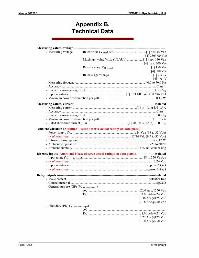
Manual 37259E SPM-D11 - Synchronizing Unit
Page 70/82 © Woodward
Appendix B. Technical Data
Measuring values, voltage ----------------------------------------------------------------------------------- - Measuring voltage Rated value (Vrated) /∆ ....................................... [1] 66/115 Vac
[4] 230/400 Vac Maximum value VPh-Ph (UL/cUL) ................... [1] max. 150 Vac [4] max. 300 Vac Rated voltage VPh-ground [1] 150 Vac [4] 300 Vac Rated surge voltage [1] 2.5 kV [4] 4.0 kV
- Measuring frequency .................................................................................... 40.0 to 70.0 Hz - Accuracy ....................................................................................................................Class 1 - Linear measuring range up to .................................................................................. 1.3 × VN - Input resistance..................................................................... [1] 0.21 MΩ, or [4] 0.696 MΩ - Maximum power consumption per path .................................................................... 0.15 W
Measuring values, current ------------------------------------------------------------------------- isolated - Measuring current .............................................................................. [1] ../1 A, or [5] ../5 A - Accuracy ....................................................................................................................Class 1 - Linear measuring range up to .................................................................................... 3.0 × IN - Maximum power consumption per path ............................................................... < 0.15 VA - Rated short-time current (1 s) ..................................................[1] 50.0 × IN, or [5] 10.0 × IN
Ambient variables (Attention! Please observe actual ratings on data plate!) --------------------- - Power supply (Vaux) ........................................................................... 24 Vdc (18 to 32 Vdc) - or alternatively ............................................................................ 12/24 Vdc (9.5 to 32 Vdc) - Intrinsic consumption ........................................................................................... max. 12 W - Ambient temperature .......................................................................................... -20 to 70 °C - Ambient humidity ............................................................................... 95 %, not condensing
Discrete inputs (Attention! Please observe actual ratings on data plate!) ----------------- isolated - Input range (VCont, dig. input) ........................................................................... 18 to 250 Vac/dc - or alternatively ..................................................................................................... 12/24 Vdc - Input resistance............................................................................................... approx. 68 kΩ - or alternatively .............................................................................................. approx. 6.8 kΩ
Relay outputs ------------------------------------------------------------------------------------------ isolated - Make contact .................................................................................................... potential free - Contact material ........................................................................................................ AgCdO - General purpose (GP) (VCont, relay output)
AC ................................................................ 2.00 Aac@250 Vac DC ................................................................. 2.00 Adc@24 Vdc 0.36 Adc@125 Vdc 0.18 Adc@250 Vdc
- Pilot duty (PD) (VCont, relay output) AC ............................................................................................... DC ................................................................. 1.00 Adc@24 Vdc 0.22 Adc@125 Vdc 0.10 Adc@250 Vdc

Manual 37259E SPM-D11 - Synchronizing Unit
© Woodward Page 71/82
Analog inputs ------------------------------------------------------------------------------- freely scaleable - Resolution .................................................................................................................... 10 Bit - 0/4 to 20 mA input ............................................................................................... load 250 Ω
Analog outputs ------------------------------------------------------------------------------- freely scalable - Resolution .................................................................................................................... 12 Bit - 0/4 to 20 mA ................................................................................. external load max. 500 Ω - 0 to 10 Vdc .........................................................................internal source resistance 500 Ω - PWM signal ............................................................................max. 10 Vdc, approx. 500 Hz
Load sharing --------------------------------------------------------------------------------------------------- - Voltage ................................................................................................................. 0 to 4 Vdc - Resistance ........................................................................................................ approx. 5 kΩ
Housing ---------------------------------------------------------------------------------------------------------- - Type ............................................................................................ APRANORM DIN 43 700 - Dimensions (W × H × D) ....................................................................... 144 × 72 × 122 mm - Front cutout (W×H) ................................................................... 138 [+1.0] × 67 [+0.7] mm - Wiring ............................................................................ Screw-type terminals depending on
plug connector 1.5 mm² or 2.5 mm² - Recommended tightening torque ............................................................. 0.4 Nm or 0.5 Nm
use 60/75 °C copper wire only use class 1 wire only or equivalent
- Weight .............................................................................................................approx. 800 g
Protection -------------------------------------------------------------------------------------------------------- - Protection system ...................................................... IP42 from front for proper installation
IP54 from front with gasket (gasket: P/N 8923-1037) IP21 from back
- Front foil .................................................................................................... insulating surface - EMV test (CE) ................................................ tested according to applicable EN guidelines
Listings CE marking, UL listing for ordinary locations UL/cUL listed, Ordinary Locations, File No.: E231544

Manual 37259E SPM-D11 - Synchronizing Unit
Page 72/82 © Woodward
Appendix C. List of Parameters
Product number P/N _____________________________ Rev _______________________________ Version SPM-D11______________________________________________________________ Project ______________________________________________________________________ Serial number S/N _______________ Date ______________________________
Option Parameter 100/400V; 1/5 A Adjustment range Standard
setting Customer settings
CONFIGURE GENERAL PARAMETERS SPRACHE/LANGUAGE german/english english G E G E Software version 6.3xxx Enter code 0000 to 9.999 XXXX Password Protection ON/OFF OFF on off on off Direct para. YES/NO NO Y N Y N
CONFIGURE BASIC SETTINGS Rated Frequency fn 48.0 to 62.0 Hz 50.0 Hz Generator freq. Set point 48.0 to 62.0 Hz 50.0 Hz Gen. voltage secondary [1] 50 to 125 V, [4] 50 to 440 V 400 V Mains voltage secondary [1] 50 to 125 V, [4] 50 to 440 V 400 V Gen. voltage primary 0.1 to 65.0 kV 0.4 kV Mains voltage primary 0.1 to 65.0 kV 0.4 kV Rated voltage Vn [1] 50 to 125 V, [4] 70 to 420 V 400 V Gen. voltage Set point [1] 50 to 125 V, [4] 50 to 440 V 400 V Current transf. Generator 10 to 9,999/x A 1000/x A Connection type Gen. 1W/1W2 1W2 1W 1W2 1W 1W2 Angle adjustment Gen. Curr -180° to 180° 000
Rated power Gen. [1] 100 to 9,999 kW [4] 5 to 9,999 kW 100 kW
CONFIGURE CONTROLLER Automatic idle - Running ON/OFF OFF on off on off
Terminal 6 Release control/Set point power Release con-trol RC SP RC SP
f control type ANALOG/PWM ANALOG Freq. controller ON/OFF ON on off on off Freq. controllerIsol. oper. ON/OFF AUS on off on off Freq. controller Ramp. 0.1 to 99.9 Hz/s 5.0 Hz/s Freq. controller Dead band 0.02 to 1.00 Hz 0.10 Hz Freq. controllerTime pulse > 10 to 250 ms 80 ms Freq. controller Gain Kp 0.1 to 99.9 15.0 f control output see table +/-20 mA
(+/-10 V)
f control output Level PWM 3.0 to 10.0 V 10.0 V PWM-signal Logic positive/negative positive f control output Init.state 0 to 100 % 50 % f control output (max.) 0 to 100 % 100 % f control output (min.) 0 to 100 % 0 % Freq. controller Gain Kp 1 to 240 15 Freq. controller Reset Tn 0.0 to 60.0 s 2.5 s Freq. controller Derivat.Tv 0.00 to 6.00 s 0.00 s

Manual 37259E SPM-D11 - Synchronizing Unit
© Woodward Page 73/82
Option Parameter 100/400V; 1/5 A Adjustment range Standard
setting Customer settings
V contr. type THREESTEP/ANALOG ANALOG T A T A Volt. controller ON/OFF ON on off on off Volt. controllerIsol. oper. ON/OFF OFF on off on off Volt. controller Ramp 1 to 99 V/s 25 V/s Volt. controller Dead band [1] 0.1 to 15.V, [4] 0.5 to 60.0 V 2.0 V Volt. controllerTime pulse> 20 to 250 ms 80 ms Volt. controller Gain Kp 0.1 to 99.9 15.0 V control output see table +/-20 mA
(+/-10 V)
V control output Init.state 0 to 100 % 50 % V control output (max.) 0 to 100 % 100 % V control output (min.) 0 to 100 % 0 % Volt. controller Gain Kp 1 to 240 15 Volt. controller Reset Tn 0.0 to 60.0 s 2.5 s Volt. controller Derivat.Tv 0.00 to 6.00 s 0.00 s Pow.fact.control ON/OFF OFF on off on off Pow.fact.control Set point i0.70 to 1.00 to c0.70 1.00 Pow.fact.control Ramp 0.01 to 0.30 /s 0.01 /s Pow.fact.control Dead band 0.5 to 25.00 % 2.5 % Pow.fact.control Gain Kp 0.1 to 99.9 15.0 Pow.fact.control Gain Kp 1 to 240 15 Pow.fact.control Reset Tn 0.0 to 60.0 s 2.5 s Pow.fact.control Derivat.Tv 0.00 to 6.00 s 0.00 s Power controller ON/OFF OFF on off on off Power controller P max 10 to 120 % 100 % Power controller P min 0 to 50 % 0 % Warm up load Set point 5 to 100 % 20 % Warm up load time 0 to 600 s 15 s Download and open GCB ON/OFF OFF on off on off Power controller P set1 = 0 to 9,999 kW 300 kW Power controller P set2 = 0 to 9,999 kW 500 kW Power set point External ON/OFF OFF on off on off Analog input 0 to 20 / 4 to 20 mA 0 to 20 mA External setp. 0mA, 4mA 0 to 9.999 kW 0 kW External setp. 20mA 0 to 9.999 kW 500 kW Power controller Ramp 1 to 999 kW/s 50 kW/s Power controller Dead band= 0.1 to 25.0 % 2.5 % Power controller Gain Kp 0.1 to 99.9 15.0 Power controller Sens.red. 1.0 to 9.9 2.0 Power controller Gain Kp 1 to 240 15 Power controller Reset Tn 0.0 to 60.0 s 2.5 s Power controller Derivat.Tv 0.00 to 6.00 s 0.00 s Gen.active-power Monitoring ON/AUS OFF on off on off Power monitoring threshold 0 to 150 % 80% Power monitoring hysteresis 0 to 100 % 20 % Power monitoring delay time 0 to 60 s 10 s Active power Load-share ON/OFF OFF on off on off Act. load share Factor 10 to 99 % 50 % Reactive power Load-share ON/OFF OFF on off on off React.load share Factor 10 to 99 % 50 %

Manual 37259E SPM-D11 - Synchronizing Unit
Page 74/82 © Woodward
Option Parameter 100/400V; 1/5 A Adjustment range Standard
setting Customer settings
CONFIGURE SYNCHRONIZATION Synchronizing functions ON/OFF ON on off on off Synchronization df max 0.02 to 0.49 Hz 0.18 Hz Synchronization df min 0.00 to -0.49 Hz -0.10 Hz Synchronization dV max [1] 1 to 20 V, [4] 1 to 60 V 24 V Synchronization Brk.hold T> 0.04 to 0.50 s 0.20 s Phase matching ON/OFF OFF on off on off Phase matching Max phase < 0 to 60° 7 ° Slip synchroniz. TClose GCB 40 to 300 ms 80 ms Slip synchroniz.Max phase < 0 to 60 ° 7 ° Phase matching Dwell time 0.2 to 10.0 s 10.0 s Phase matching Gain 1 to 36 2 Phase matching df start 0.02 to 0.25 Hz 0.20 Hz
CONFIGURE SYNCHRONIZATION TIME MONITORING Sync.time contr. ON/OFF OFF on off on off Sync.time contr. Delay time 10 to 999 s 120 s
CONFIGURE DEAD BUS START Gen. circ.break.Gen.schalter ON/OFF OFF on off on off Dead bus op. GCB df max 0.05 to 5.00 Hz 0.25 Hz Dead bus op. GCB dV max [1] 1 to 20 V, [4] 1 to 60 V 40 V
CONFIGURE MONITORING Reverse/min.pow. Monitoring ON/OFF OFF on off on off Reverse/min.pow. Threshold -99 to 99 % -20 % Reverse/min.pow. Delay 0.1 to 99.9 s 1.0 s Gen. overload Monitoring ON/OFF OFF on off on off Gen. overload Threshold. 0 to 150 % 120 % Gen. overload Delay time 0 to 99 s 20 s Gen.frequency- Monitoring ON/OFF OFF on off on off Gen. overfreq. f > 40.0 to 70.0 Hz 55.0 Hz Gen. overfreq. Delay time 0.04 to 9.98 s 3.00 s Gen. underfreq. f < 40.0 to 70.0 Hz 45.0 Hz Gen. underfreq. Delay time 0.04 to 9.98 s 3.00 s Gen.voltage- Monitoring ON/OFF OFF on off on off Gen.overvoltage U > [1] 20 to 150 V; [4] 20 to 520 V 460 V Gen.overvoltage Delay time 0.04 to 9.98 s 3.00 s Gen.undervoltage U < [1] 20 to 150 V; [4] 20 to -520 V 340V Gen.undervoltage Delay time 0.04 to 9.98 s 3.00 s Auto-acknowledge Messages ON/OFF ON on off on off Acknowledge Message aft 1 to 99 s 1 s
CONFIGURE PASSWORD Define level 1 code 0000 to 9999 0001 Define level 2 code 0000 to 9999 0002

Manual 37259E SPM-D11 - Synchronizing Unit
© Woodward Page 75/82
Appendix D. Power Factor Definition
The phasor diagram is used from the generator's view. This defines the following definitions. Power Factor is defined as a ratio of the real power to apparent power. In a purely resistive circuit, the voltage and current waveforms are instep resulting in a ratio or power factor of 1.00 (often referred to as unity). In an in-ductive circuit the current lags behind the voltage waveform resulting in usable power (real power) and unusable power (reactive power). This results in a positive ratio or lagging power factor (i.e. 0.85lagging). In a capacitive circuit the current waveform leads the voltage waveform resulting in usable power (real power) and unusable power (reactive power). This results in a negative ratio or a leading power factor (i.e. 0.85leading). Inductive: Electrical load whose current waveform lags the voltage waveform thus having a lagging power fac-tor. Some inductive loads such as electric motors have a large startup current requirement resulting in lagging power factors.
Capacitive: Electrical load whose current waveform leads the voltage waveform thus having a leading power factor. Some capacitive loads such as capacitor banks or buried cable result in leading power factors.
Different power factor displays at the unit: i0.91 (inductive) lg.91 (lagging)
c0.93 (capacitive) ld.93 (leading)
Reactive power display at the unit: 70 kvar (positive) -60 kvar (negative) Output at the interface: + (positive) - (negative) In relation to the voltage, the current is lagging leading The generator is over excited under excited Control: If the control unit is equipped with a power factor controller A voltage lower "-" signal is output as long as the measured value is "more inductive" than the reference set point Example: measured = i0.91; set point = i0.95
A voltage raise "+" signal is output as long as the meas-ured value is "more capacitive" than the reference set point Example: measured = c0.91; set point = c0.95

Manual 37259E SPM-D11 - Synchronizing Unit
Page 76/82 © Woodward
Phasor diagram: inductive capacitive

Manual 37259E SPM-D11 - Synchronizing Unit
© Woodward Page 77/82
Appendix E. Service Options
Product Service Options ≡≡≡≡≡≡≡≡≡≡≡≡≡≡≡≡≡≡≡≡≡≡≡≡≡
The following factory options are available for servicing Woodward equipment, based on the standard Woodward Product and Service Warranty (5-01-1205) that is in effect at the time the product is purchased from Woodward or the service is performed. If you are experiencing problems with installation or unsatisfactory performance of an installed system, the following options are available: • Consult the troubleshooting guide in the manual. • Contact Woodward technical assistance (see "How to Contact Woodward" later in this chapter) and discuss
your problem. In most cases, your problem can be resolved over the phone. If not, you can select which course of action you wish to pursue based on the available services listed in this section.
Returning Equipment for Repair ≡≡≡≡≡≡≡≡≡≡≡≡≡≡≡≡≡≡≡≡≡≡≡≡≡
If a control (or any part of an electronic control) is to be returned to Woodward for repair, please contact Wood-ward in advance to obtain a Return Authorization Number. When shipping the control(s), attach a tag with the fol-lowing information: • name and location where the control is installed • name and phone number of contact person • complete Woodward part numbers (P/N) and serial number (S/N) • description of the problem • instructions describing the desired repair
CAUTION To prevent damage to electronic components caused by improper handling, read and observe the pre-cautions in Woodward manual 82715, Guide for Handling and Protection of Electronic Controls, Printed Circuit Boards, and Modules.
Manual 37259E SPM-D11 - Synchronizing Unit
Page 78/82 © Woodward
Packing a Control Use the following materials when returning a complete control: • protective caps on any connectors • antistatic protective bags on all electronic modules • packing materials that will not damage the surface of the control • at least 100 mm (4 inches) of tightly packed, industry-approved packing material • a packing carton with double walls • a strong tape around the outside of the carton for increased strength
Return Authorization Number RAN When returning equipment to Woodward, please telephone and ask for the Customer Service Department in Stuttgart [+49 (0) 711-789 54-0]. They will help expedite the processing of your order through our distributors or local service facility. To expedite the repair process, contact Woodward in advance to obtain a Return Authoriza-tion Number, and arrange for issue of a purchase order for the control(s) to be repaired. No work can be started until a purchase order is received.
NOTE We highly recommend that you make arrangement in advance for return shipments. Contact a Wood-ward customer service representative at +49 (0) 711-789 54-0 for instructions and for a Return Authori-zation Number.
Replacement Parts ≡≡≡≡≡≡≡≡≡≡≡≡≡≡≡≡≡≡≡≡≡≡≡≡≡
When ordering replacement parts for controls, include the following information: • the part numbers P/N (XXXX-XXX) that is on the enclosure nameplate • the unit serial number S/N, which is also on the nameplate

Manual 37259E SPM-D11 - Synchronizing Unit
© Woodward Page 79/82
How to contact Woodward ≡≡≡≡≡≡≡≡≡≡≡≡≡≡≡≡≡≡≡≡≡≡≡≡≡
Please contact following address if you have questions or if you want to send a product for repair: Woodward GmbH Handwerkstrasse 29 70565 Stuttgart - Germany Phone: +49 (0) 711-789 54-0 (8.00 - 16.30 German time) Fax: +49 (0) 711-789 54-100 e-mail: [email protected] For assistance outside Germany, call one of the following international Woodward facilities to obtain the address and phone number of the facility nearest your location where you will be able to get information and service. Facility Phone number USA +1 (970) 482 5811 India +91 (129) 409 7100 Brazil +55 (19) 3708 4800 Japan +81 (476) 93 4661 The Netherlands +31 (23) 566 1111 You can also contact the Woodward Customer Service Department or consult our worldwide directory on Wood-ward’s website (www.woodward.com) for the name of your nearest Woodward distributor or service facility. [For worldwide directory information, go to www.woodward.com/ic/locations.]

Manual 37259E SPM-D11 - Synchronizing Unit
Page 80/82 © Woodward
Engineering Services ≡≡≡≡≡≡≡≡≡≡≡≡≡≡≡≡≡≡≡≡≡≡≡≡≡
Woodward Industrial Controls Engineering Services offers the following after-sales support for Woodward prod-ucts. For these services, you can contact us by telephone, by e-mail, or through the Woodward website. • Technical support • Product training • Field service during commissioning Technical Support is available through our many worldwide locations, through our authorized distributors, or through GE Global Controls Services, depending on the product. This service can assist you with technical ques-tions or problem solving during normal business hours. Emergency assistance is also available during non-business hours by phoning our toll-free number and stating the urgency of your problem. For technical engineer-ing support, please contact us via our toll-free or local phone numbers, e-mail us, or use our website and reference technical support. Product Training is available on-site from several of our worldwide facilities, at your location, or from GE Global Controls Services, depending on the product. This training, conducted by experienced personnel, will as-sure that you will be able to maintain system reliability and availability. For information concerning training, please contact us via our toll-free or local phone numbers, e-mail us, or use our website and reference customer training. Field Service engineering on-site support is available, depending on the product and location, from our facility in Colorado, or from one of many worldwide Woodward offices or authorized distributors. Field engineers are expe-rienced on both Woodward products as well as on much of the non-Woodward equipment with which our prod-ucts interface. For field service engineering assistance, please contact us via our toll-free or local phone numbers, e-mail us, or use our website and reference field service.

Manual 37259E SPM-D11 - Synchronizing Unit
© Woodward Page 81/82
Technical Assistance ≡≡≡≡≡≡≡≡≡≡≡≡≡≡≡≡≡≡≡≡≡≡≡≡≡
If you need to telephone for technical assistance, you will need to provide the following information. Please write it down here before phoning: Contact Your company _____________________________________________ Your name ________________________________________________ Phone number _____________________________________________ Fax number _______________________________________________ Control (see name plate) Unit no. and Revision: P/N: ____________________ REV: _______ Control type SPM-D11 ____________________________ Serial number S/N _________________________________ Description of your problem _________________________________________________________ _________________________________________________________ _________________________________________________________ _________________________________________________________ _________________________________________________________ _________________________________________________________ Please be sure you have a list of all parameters available.

We appreciate your comments about the content of our publications.
Please send comments to: [email protected] Please include the manual number from the front cover of this publication.
Woodward GmbH Handwerkstrasse 29 - 70565 Stuttgart - Germany
Telefon +49 (0) 711-789 54-0 • Fax +49 (0) 711-789 54-100 [email protected]
Homepage
http://www.woodward.com/power
Woodward has company-owned plants, subsidiaries, and branches, as well as authorized distributors and other authorized service and sales facilities throughout the world.
Complete address/phone/fax/e-mail information
for all locations is available on our website (www.woodward.com).
2011/6/Stuttgart