spray control for maximizing energy effi- …multiphase.asu.edu/paper/aas_2012.pdfatomization and...
TRANSCRIPT

Atomization and Sprays,x(x): xxx–xxx (2012)
SPRAY CONTROL FOR MAXIMIZING ENERGY EFFI-CIENCY AND REDUCING EMISSION IN COMBUSTIONENGINES
N. Chigier,1,∗ W. Bachalo,2 R. Reitz,3 J. Bellan,4 & M. Herrmann5
1Department of Mechanical Engineering, Carnegie Mellon University, Pittsburgh, PA
2Artium Technologies, Inc., 150 West Iowa Avenue, Unit 202, Sunnyvale, CA
3Engine Research Center, University of Wisconsin-Madison,WI
4Jet Propulsion Laboratory, California Institute of Technology, Pasadena, CA
5School for Engineering of Matter, Transport and Energy, Arizona State University, Tempe, AZ
∗Address all correspondence to N. Chigier E-mail: [email protected]
Original Manuscript Submitted: 5/8/2011; Final Draft Received: 01/10/2012
Combustion engines for automotive, locomotive, land, shipand aircraft, utilize liquid fuel injected into combustionchambers. Projected increases in the price of fuel and effects of emissions on pollution and climate change are requir-ing increased efforts to increase combustion and energy efficiency within combustion chambers together with minimiz-ing emission of particulates, oxides of nitrogen and sulfurand other pollutants, including CO2. The question that isbeing addressed is how research can contribute to the objective of improving the efficiency of engines using liquid fueland reducing the amount of pollutants generated in the energy conversion process by control of drop size, velocity andtrajectory and local air/fuel mixture ratios which have a dominant influence on ignition, combustion and exhaust emis-sions. Basic predictions of global spray combustion phenomena may not result in sufficient understanding that can leadto the necessary improvements. Advancing our knowledge of the associated phenomena with careful experimentationand modeling can hold the key to a deeper understanding of theinvolved processes and thus can result in the requiredimprovements. This paper provides a brief overview about the current state and challenges in some of the key researchareas related to understanding the processes involved in liquid fuel combustion. It represents a summary of a Forumdiscussion titled “Spray Control for Maximizing Energy Efficiency and Reducing Emission in Combustion Engines”held at the ILASS-Americas 22nd Annual Conference on LiquidAtomization and Spray Systems in Cincinnati, OH.
KEY WORDS: spray combustion; experiment; simulation
1. INTRODUCTION
It is a well accepted fact that changes are necessary inproviding for our energy requirements. Since it remainsunknown what these changes will be, it is expected thatfor the foreseeable future combustion will remain a keyprocess in providing our energy needs. Despite realiz-
ing significant benefits from combustion of fossil fuels,this practice continues to have consequential negative im-pacts on the world; including deleterious health effectsdue to combustion generated pollutants including partic-ulates, anthropogenic climate change due to CO2 releaseand soot, and photochemical smog. Maintaining secure
1044–5110/10/$35.00 c© 2012 by Begell House, Inc. 1
2 Chigier et al.
sources of energy also leads to local and large-scale mil-itary conflicts which can be expected to heighten as de-mands increase and supply begins to diminish. It is there-fore imperative that we manage these finite resources asefficiently and effectively as possible. Some argue that itis even immoral to burn fossil fuels since these are pre-cious resources needed in manufacturing plastics, syn-thetic rubber, dyes, lubrication, etc., now and for futuregenerations (Abbott, 2010). Until other sources of en-ergy are devised, we must strive to build highly efficientcombustion systems that make the most use of these non-renewable resources.
A vast amount of our energy is derived from burningfossil fuels through spray combustion. Drop size, ve-locity and trajectory play primary roles in determiningair-fuel mixture ratios, ignition, combustion and exhaustemissions. These in turn are influenced by the physicaland chemical properties of the fuel, fuel injector geome-try, liquid jet breakup, atomization, vaporization, fuel-airmixing, residence time, temperature and species concen-tration distributions, heat and mass transfer.
A wide range of atomizers has been developed andstudied. Tangential injection of liquid and air in nozzlesgenerates swirling flows with high shear which are ben-eficial to efficient atomization. Acoustic and ultrasonicvibrations applied to nozzles facilitate liquid breakup,particularly for high viscosity liquids. Piezo-electric in-jectors provide more precise control of injection dura-tion. Injection of gas bubbles and cavitation in nozzlesstrongly enhance atomization. Recent studies have shownthat reducing orifice size and increasing injection pres-sures, generates smaller drop size and consequently in-creased gas entrainment into the spray. Smaller drop sizeincreases surface contact between fuel and air as wellas generating higher turbulence which enhances entrain-ment and fuel evaporation. Consequently ignition delayis shortened and this leads to decrease in emission of par-ticulates.
The traditional single-hole injector for diesel enginesis in the process of being replaced by multi-hole orifices,where groups of micro-orifices, close together, with smallangles between the orifices, allow variation of momen-tum and penetration of the spray. Clusters of small ori-fices generate sprays which entrain larger mass of ambi-ent gas and result in higher rates of evaporation. Spraytip penetration is shorter than single hole sprays and de-position of liquid on surfaces is reduced. With group-holenozzles, premixed combustion has been achieved with re-duced particulate matter and reduced NOx emissions as aresult of leaner and more homogeneous fuel/air mixture
ratios. Increasing fuel injection pressures results in for-mation of more homogeneous fuel/air mixture ratios.
Airblast atomization increases liquid breakup and gen-erates leaner air/fuel mixture ratios and consequentlylower soot, CO and NOx emissions. During cold start,particularly in cold climates, combustion is unstable re-sulting in emission of CO, HC, and soot.
Impaction of drops on wall surfaces generates liquidwall films which have significant adverse effects on en-gine performance and emissions. This is of special im-portance in small bore diesel engines that have a higherincidence of wall impingement. The density, surface ten-sion and viscosity of the fuel, coupled with droplet size,angle of impaction and velocity as well as surface temper-ature, roughness and thickness of the wall layer, governwhether droplets will stick, rebound, breakup, splash orform a liquid film on the surface. Liquid fuel films on hotsurfaces generate coke and increase HC emissions partic-ulate matter. Drop size, momentum and trajectories needto be controlled to avoid drop impact on wall surfaces.
Finally, alternative fuels such as biodiesel, ethanol, andbio-derivative fuels have significantly different viscosi-ties, surfaces tension and chemical properties than con-ventional fuels and hence require adjustments to fuel in-jection systems.
The question that is being addressed here is how re-search can contribute to the objective of improving theefficiency of engines using liquid fuel and reducing theamount of pollutants generated in the energy conversionprocess by control of drop size, velocity and trajectoryand local air/fuel mixture ratios which have a dominantinfluence on ignition, combustion and exhaust emissions.Great progress has been made in computational numericalsimulations of fuel injection and combustion. These sim-ulations provide important tools in engine developmentand can provide deeper understanding of spray and com-bustion processes. Simulations include: fuel injection,liquid jet and drop breakup, droplet collision, evaporation,turbulence, mixture formation and their significant impacton autoignition and heat release. However, despite therecognized progress, there may not yet be sufficient un-derstanding of global spray combustion phenomena, andtherefore basic predictions may not yet provide the infor-mation necessary to desired improvements. Advancingour knowledge of spray phenomena with careful exper-imentation and modeling may hold the key to a deeperunderstanding of the involved processes, and thus couldresult in the required improvements.
From the experimental viewpoint the diagnostics haveevolved to provide a wide range of possibilities for ac-
Atomization and Sprays

Spray Control for Maximizing Energy Efficiency and ReducingEmission in Combustion Engines 3
curate measurements. Optically clear quartz casingsand pistons permit diagnostic measurement of both coldsprays and spray combustion. A wide range of instru-ments are available for measurement of spray and com-bustion systems including: high speed motion photogra-phy, particle image velocimetry, phase Doppler particleanalyzers, digital holography, optical interferometry, laserinduced fluorescence, elastic and laser absorption scatter-ing, Mie scattering and shadowgraphy, spontaneous Ra-man, ultraviolet laser absorption, laser induced fluores-cence and high energy X-ray radiography.
The following sections provide a brief overview aboutthe current state and challenges in some of the key re-search areas related to understanding the processes in-volved in liquid fuel combustion. These sections are notintended to be a comprehensive review of the respectivetopics, but rather represent a summary of a Forum discus-sion titled “Spray Control for Maximizing Energy Effi-ciency and Reducing Emission in Combustion Engines”held at the ILASS-Americas 22nd Annual Conferenceon Liquid Atomization and Spray Systems in Cincinnati,OH.
2. SPRAY CHARACTERIZATION: A REQUIRE-MENT FOR GREATER COMBUSTION EFFI-CIENCY AND POLLUTANT EMISSIONS RE-DUCTION
Over the past decades, significant progress has been madein the development of diagnostics and modeling of spraycombustion. Subsequently, this has resulted in improve-ments to our understanding of the processes needed forachieving combustion efficiency and emissions reduction.In just over three decades, we have advanced from a prim-itive level of investigation to making detailed spray mea-surements in situ and efficiently in complex spray flowswith good accuracy, precision, and resolution. Opticaldiagnostics continue to be a key means for measuringthese complex reacting spray flows including spray for-mation, in situ drop size and velocity characterization,droplet number density and volume flux measurements.These methods are also essential for investigating the sub-sequent complex turbulent two-phase flows that are asso-ciated with all spray combustion systems. These auto-mated measurements not only include drop size distribu-tions at points within the spray field, but also measure-ments of the droplet size, velocity, and angle of trajec-tory for individual droplets in these complex flows. Gasphase flows including mean and turbulence velocities canbe measured in the presence of the dispersed phase sim-
ply by restricting the measurements to very small particlesthat will track the gas phase accurately. Measurementscan now be made in relatively dense sprays, a capabilitythat was only dreamed of a few decades ago. Further-more, in situ droplet size, velocity, and temperature havebeen measured in spray flames (Sankar et al., 1994, 1997).
Advancement of optical diagnostics has providedmeans to penetrate the complexities of reacting sprayflows and, consequently, has contributed to significant ad-vances in spray combustion in gas turbine, spark ignition,and diesel engines as well as in industrial liquid-fueledcombustors. For example, it is becoming more commonfor direct fuel injection at high pressure to be used to re-duce droplet size and enhance fuel distribution and mix-ing in the combustion chamber. This strategy is rapidlybeing adopted for spark ignition engines. Unfortunately,direct injection systems can lead to fuel rich zones andwall wetting and consequently, to soot production. Evo-lution of such injection strategies has been enabled by theavailability of spray diagnostics that are capable of char-acterizing spray behavior in very complex reacting flowenvironments.
2.1 Ensemble Light Scatter Detection Methods
Of the available optical methods, the Fraunhofer diffrac-tion method; also known as laser diffraction, ensemblelight scatter detection, etc. was one of the first meth-ods capable of probing sprays with realistic droplet num-ber densities. Single particle counting systems availableat that time were based on forward scatter light detec-tion. This resulted in sample volumes that were too largeto handle spray drop number densities even in relativelydilute sprays. Ensemble methods succeeded since theywere able to measure sprays with relatively higher dropletnumber densities. The method utilizes cumulatively scat-tered light energy produced by particles throughout theexposed laser beam which is integrated over ring detec-tors located in the Fourier transform plane of the receiverlens. In the near forward direction, the scattered light in-tensity distribution has an intensity distribution propor-tional to droplet diameter squared and an angular distri-bution inversely proportional to the particle size. Thismethod is by now well-known and has been described innumerous articles (Heuer and Leschonski, 1985; Hirle-man, 1983; Swithenbank et al., 1977). The method hasbeen evaluated through comparison to other methods aswell as performing measurements on well-characterizedparticles (Dodge, 1984). Some questions have remainedregarding the performance of the method and the use of
Volume x, Number x, 2012

4 Chigier et al.
the simplified Fraunhofer diffraction theory to describelight scattering when measuring sprays (Bachalo, 2004).It was demonstrated that the Fraunhofer diffraction the-ory could lead to error in estimating the model indepen-dent size distribution when measuring sprays composedof transparent droplets. Instrument manufacturers havenow recognized this as a source of measurement uncer-tainty and have turned to the Mie theory, which reliablydescribes complete light scattering by uniformly illumi-nated spherical particles. Of course, the measurementscan no longer be claimed to be independent of the dropletproperties or shape.
An apparent unfortunate consequence of using the en-semble method is that spray characterizations typicallymust be made in cold spray flows with only limited evap-oration. Very early, it was observed that the ensemblemethod could not make reliable measurements in react-ing spray flows due to beam steering caused by thermally-induced refractive index fluctuations. However, informa-tion is needed in combusting spray environments, whichare quite different from the cold flow conditions. It issomewhat ironic that gas turbine sprays, for example,with very high number densities when measured undercold conditions challenge the measurement techniques.But the droplet number density decreases significantlyin a burning spray environment since the small dropletsevaporate very rapidly. Methods not troubled by beamsteering actually perform better when measuring react-ing sprays with lower number densities. The approachof measuring just cold sprays is a useful starting point butmeasurements need to be made in reacting spray flows.Nonetheless, the ensemble light scattering method hasprovided significant information on sprays and was heav-ily used in the early days of developing spray correlations,especially for gas turbine applications.
2.2 Phase Doppler Interferometry
Introduction of phase Doppler interferometry (Bachalo,1980; Bachalo and Houser, 1984) represented a signifi-cant step forward in our ability to directly measure dropsize distributions without the need to employ distributionfunctions or to invert ill-posed, ill-conditioned integralequations. Developed as a means for measuring spraybehavior within turbulent reacting flows associated withgas turbine combustion (Bachalo and Houser, 1985), themethod has been demonstrated to be capable of makingreliable spray measurements in these environments. Si-multaneous measurements of drop size and velocity aswell as the gas phase turbulence in the presence of a
dispersed phase are now possible. This new capabil-ity allowed characterization of spray combustion as tur-bulent two-phase evaporating and reacting flows. Themethod represents a robust technique for such applica-tions since the measurements are based on the wavelengthof light which does not change through interaction withthe spray environment, including scattering by the inter-vening spray drops and combustion generated particulatesin the laser beam. Phase Doppler interferometry dependsupon the coherence of the laser beam at the measurementpoint. Hence, multiply scattered light does not partici-pate in the spray measurements. Only laser beam photonsthat have not scattered but penetrate to the measurementpoint produce a coherent signal that is used in characteriz-ing the droplet size and velocity. Scattered light reachingthe receiver may undergo extinction but multiple scatter-ing which may affect the signal-to-noise ratio does notaffect the information used in obtaining particle velocityand size. Measurements are made at a point (very smallvolume) and light multiply scattered from outside of themeasurement volume is not detected.
One of the limitations of single particle counting meth-ods when applied to dense spray measurements has beenthe requirement of having a high probability of only oneparticle residing in the sample volume at one time. Alarge factor in the success of the phase Doppler methodis the use of off-axis light scatter detection which sig-nificantly reduced and allowed much greater control onthe size of the sample volume (Bachalo, 1980). Modernphase Doppler instruments can use sample volumes thatare as small or smaller than the largest drop being mea-sured. Using more powerful lasers to overcome light ex-tinction, small sample volumes to minimize the probabil-ity of droplet coincident occurrences and modern digitalsampling and Fourier transform signal processing has al-lowed measurements in very high droplet number densitysprays. In recent years, proprietary developments havebeen introduced enabling the method to make reliablemeasurements in sprays with even greater number den-sities (mean droplet separation less that 10 mean dropletdiameters).
Fuel spray combustion relies heavily upon understand-ing the spray droplet dynamics and complex relationshipsbetween the turbulent two-phase flow and the chemistryinvolved in spray combustion. Spray combustion phe-nomena represent a complex exchange of mass, momen-tum, species, and energy within a heterogeneous environ-ment and over a large range of length and time scales.It is well-known that there is a significant interaction be-tween the dispersed phase and the gas phase turbulence.
Atomization and Sprays

Spray Control for Maximizing Energy Efficiency and ReducingEmission in Combustion Engines 5
Greater detail in the measurements of turbulent transportof droplets within these highly turbulent, highly transientenvironments is essential to the evolution and refinementof spray combustion methodologies. For example, in re-ciprocating engines, droplet injection momentum needsto be characterized to evaluate the probability of such un-desirable phenomena as wall and piston head wetting. Awidely varying range of turbulence length scales in thegas phase can be expected to occur during compression.These phenomena affect the dispersion of the drops andmixing.
Detailed measurements of complex transient phenom-ena are generally lacking. For example, the normal andshear stress components of the kinetic stresses to whichthe droplets are subjected need to be characterized. Mech-anisms of turbulent transport of droplets and fuel vaporinside and at the boundaries of the spray plume lead-ing to concentration gradients in the fuel-air mixing needto be measured. More information is required on thegas phase and droplet transport statistics in these highReynolds number transient spray flows. Obtaining suchmeasurements in situ may be very difficult or impossible.Scaled experiments focusing on different aspects of thesecomplex processes must be made and detailed measure-ments of the turbulent transport phenomena characterizedto help guide the development of submodels, essential topredicting the spray behavior. Although turbulent mix-ing of sprays and the interaction with the turbulent flowcan be characterized even in reacting environments usingphase Doppler interferometry, the method has not beenfully exploited in the investigation of these highly com-plex spray flows and spray combustion environments. Toooften, basic measurements of drop size distributions anddrop size versus velocity have been considered sufficientto characterize the spray flow. Investigations associatedwith spray combustion phenomena require that measure-ments should be made in highly evaporating and reactingenvironments which are closer simulations of the actualspray combustion environments. Global descriptions ofthe fuel/air mixing within the cylinder can only lead toconjecture as to the details of the air mixing and com-bustion phenomena within the combustion chamber. Theglobal measurements of combustion energy and pollutantemissions provide useful information, but do not revealthe internal details that may expedite a greater under-standing of the fuel-air mixing and combustion processesinvolved.
Statements have been made that optical methods can-not obtain measurements in dense sprays, especially nearinjector exits (Cai et al., 2003; Kastengren et al., 2008).
These statements need to be qualified as to what is meantby a dense spray. Typically, it is not a dense spray, butspray formation that is referred to in these comments.This includes injected liquid that is undergoing breakupwith an intact liquid core and large ligaments. Methodsdesigned for measuring sprays (dispersed liquid in theform of droplets) cannot be expected to produce reliabledrop size measurements where drops do not exist or theconditions are mixed. These regions are best character-ized using imaging methods since there are random liquidstructures present in addition to droplets that cannot beproperly described by a size distribution or mean dropletsize. Moving forward, the obvious difficulty, if not im-possibility of making detailed measurements within thesenozzle flows will undoubtedly require the use of CFDmodeling and appropriate submodels. Unfortunately, themodeling efforts still require experimental data for devel-opment and verification. In this case, modeling the scaledup flow model and direct comparisons with measurementsseems to be the only recourse available. A closer integra-tion of experimentation and modeling becomes essentialif further advances are to be made in a timely manner.
2.3 Optical Imaging of Spray Formation
Using basic imaging techniques, important qualitativeand quantitative information may be gained near the in-jector exit region where liquid jets break up to form thespray. It is well-known that the combustion character-istics are significantly influenced by the mixing processwhich originates near to the nozzle tip and subsequentfuel-air mixing. This region is often referred to as thedense spray region but preferably, should be described asthe spray formation region. Generally, in this region amajority of droplets have not yet formed and the highlyconcentrated mixed structures of intact core, ligaments,and droplets present a significant challenge to the mea-surement techniques. Nonetheless, this is an importantregion of the phenomena since it influences the subse-quent development of the spray size distribution and ofthe spray flow dynamics. Properly illuminated imagesof these liquid breakup mechanisms can reveal a wealthof qualitative and quantitative information on the mech-anisms of spray formation. Shadowgraph imaging usingpulsed lasers for illumination and high-resolution-, high-speed-, high-frame rate digital cameras provide excellentdetail in the important region of spray formation. For ex-ample, advanced optical imaging methods utilizing veryfast, high resolution CMOS cameras have been appliedto studies of the spray formation region to better investi-
Volume x, Number x, 2012

6 Chigier et al.
gate this important early stage of the spray development(Bolszo et al., 2010). Once again, creative lighting ofthe sprays using laser light sheets or simultaneously usingboth back-lighted and front-lighted imaging can produceremarkable detail on the spray formation characteristics(Smallwood et al., 1994). For very high pressure dieselinjection studies, it may be necessary to use nanosecond,picosecond or even femtosecond laser pulse durations toadequately freeze images of the flow structures. Incor-porating double pulse imaging can produce quantitativeinformation on the motion of the various structures dur-ing spray formation as well as on the spatial wavelengthsassociated with the breakup processes.
Unfortunately, in higher liquid structure and spray den-sity regions, photons will be multiply scattered to a signif-icant degree. Strictly, multiple scattering occurs with asfew as two droplets or structures in the beam path but thedegree of multiple scattering becomes a concern when asignificant percentage of the photons are multiply scat-tered. Multiply-scattered photons can reach the imageplane from different directions illuminating and distort-ing what should otherwise be representative shadows ofthe spray structures and drops. It must be emphasized thatthere is not a hard and fast point where multiple scatteringbecomes a serious problem; it is a continuum with the lossof image quality progressing in proportion to the degreeof multiple light scattering. At some point, the signal-to-noise ratio degenerates to a level where other measuresare required to deal with the problem.
Holographic imaging may be one of the earliest meansof mitigating the effects of multiple scattering on the im-ages of dense sprays (Trolinger and Bachalo, 1977, 1980).An often missed advantage of holographic imaging is thefact that it is a heterodyning approach wherein interfer-ometry is used in recording information on the amplitudeand phase of the light waves. As such, only coherent lightor ballistic photons participate in the formation and recon-struction of the image. Multiply-scattered light appears asbackground noise but does not produce a significant con-tribution to the recording and reconstruction of the image.
Significant development in ballistic imaging has beencarried out by a number of researchers(Linne et al., 2006;Sedarsky et al., 2009, 2006). This method improves theshadow images considerably when light beam extinctionby spray droplets and obscuration by larger scale struc-tures is very high (greater than 90%). The method utilizesfemtosecond laser light pulses for illuminating the sprayand a very fast acousto-optical shutter to block the mul-tiply scattered photons. Ballistic photons which are notscattered by spray structures or that only undergo small
angle light scattering will reach the shutter plane earlierthan the multiply scattered photons. These early photonsthat emerge from the object field are captured and producea line-of-sight shadow image of the structures and largerdroplets in the spray formation. The multiply-scatteredphotons are blocked from participating in the formation ofthe image or more specifically, in the obscuration of theshadow image. Removal of the multiply scattered pho-tons allow observation of the internal structures in verydense spray formation regions. Although these methodsonly provide line of sight information, they do offer valu-able information that is useful in understanding the com-plexities of spray formation. With the available lasers anddetectors, this method is now easier to apply and can beused for shadowgraph imaging in sprays that range fromdilute to spray regions that have very high light extinctionand obscuration.
3. TOWARD 60% THERMAL EFFICIENCY, LOW-EMISSIONS INTERNAL COMBUSTION EN-GINES VIA OPTIMIZED FUEL REACTIVITYCONTROL
The above review summarizes major advances in spraydiagnostics that have occurred over the past 3 decades.Thanks to these advances it is now possible to providedetailed validation data for engine sprays. This has al-lowed the development of more reliable submodels thathave been integrated into engine Computational Fluid Dy-namics (CFD) codes. These codes include the capabilityto represent moving meshes for the piston and valves, andthey provide submodels to handle the turbulent compress-ible flows with spray and droplet evaporation and com-plex fuel combustion chemistry that characterize engines.It is now widely recognized that engine CFD model sim-ulations can offer significant advantages and can supple-ment experimental measurements in the engine develop-ment process by providing detailed in-cylinder informa-tion, which is normally not available or is inaccessiblein experiments. This section presents an example appli-cation where CFD modeling has been applied to studynew low temperature combustion concepts called Homo-geneous Charge Compression Ignition (HCCI), PremixedCharge Compression Ignition (PCCI) and Reactivity Con-trolled Compression Ignition (RCCI). These regimes ofoperation offer the promise of dramatically improved en-gine efficiencies.
To begin, it is useful to review the current status ofengine efficiencies. Once supplied with electricity, elec-tric motors are more than 96% energy-efficient. How-
Atomization and Sprays

Spray Control for Maximizing Energy Efficiency and ReducingEmission in Combustion Engines 7
ever, complex combustion, heat transfer and fluid-flowprocesses limit the efficiencies of electric power genera-tion devices. For example, typical light-water reactor nu-clear power plants have thermal efficiencies of only about35% (thermal efficiency is defined as useful work out-put divided by energy input in the fuel). A modern coal-powered electricity generation plant with a super-criticalboiler is about 44% efficient. State-of-the-art gas turbineshave efficiencies in the 40% to 46% range in simple-cycleoperation. However, if the turbine exhaust is input to asteam turbine to create a combined-cycle power plant,efficiencies are expected to reach beyond 60%. Detailsabout the performance of such advanced Steam and Natu-ral Gas (STAG) H-class power generation equipment areavailable in trade publications from General Electric, Mit-subishi, and Siemens Power Generation, for example. Itshould be noted that the achievement of these high effi-ciencies is the result of intense research efforts that havebeen carried out over decades of development. As an ex-ample of the advanced technologies employed, the tur-bines feature nozzle and bucket materials with thermalbarrier coatings for heat transfer control, together withcomplex 3-stage, lean pre-mix Dry Low NOx combustionstrategies.
By comparison, the automotive Spark-Ignition (SI) in-ternal combustion engine, equipped with its 3-way cata-lyst for emission control, has a thermal efficiency of onlyabout 30% (Heywood, 1988). On the other hand, dieselengines are about 35% more fuel efficient than SI engines,and are therefore among the most efficient engines in ex-istence with thermal efficiencies exceeding 50% for largemarine engines. This explains why diesel engines havebeen so widely used commercially, especially for heavy-duty applications and transportation. However, moderndiesel engines are required to meet stringent emissionstandards, and NOx and soot emission reductions of morethan 95% have been mandated by the Environmental Pro-tection Agency (EPA) over past 20 years.
Unfortunately, measures introduced to meet emissionsmandates, such as the use of non-optimal fuel injec-tion timings, large amounts of Exhaust Gas Recirculation(EGR) or ultra-high injection pressures tend to reducediesel engine fuel efficiencies and also to increase engineexpense. As a result, many engine manufacturers haveelected to use Selective Catalytic Reduction (SCR) ex-haust after-treatment for NOx reduction. However, withSCR there is also a fuel penalty since a reducing agentsuch as urea (carbamide - (NH2)2CO) must be sprayedinto the exhaust stream at rates (and cost) of about 1%of the fuel flow rate for every 1 g/kWh of NOx reduction
desired. Soot control is achieved using Diesel ParticulateFilters (DPF), which generally require periodic regener-ation. This is achieved by adjusting the fuel-air mixturestrength so as to increase exhaust temperatures to burnoff the accumulated soot, and is accompanied by an addi-tional fuel efficiency penalty that can be as much as 3%.
The desire to increase internal combustion engine fuelefficiency while simultaneously meeting emissions man-dates has motivated considerable research into new com-bustion regimes, including Homogeneous Charge Com-pression Ignition (HCCI) and Partially Premixed chargeCompression Ignition (PCCI). Figure 1 shows predictedsoot, NOx and CO (indicative of unburned fuel) emissiontrends as a function of the local in-cylinder fuel-air equiv-alence ratio (unity equals chemically correct) and the lo-cal peak combustion temperature (Park and Reitz, 2007).In conventional diesel combustion locations exist withinthe combustion chamber, which span both the fuel-rich,soot-forming, and the high temperature, NOx-producingregions. H/PCCI compression ignition strategies attemptto avoid both flame propagation, which results in highburned gas temperatures in SI engines, and diesel diffu-sion combustion, which leads to high local temperaturesand rich mixtures.
As can be seen in Fig. 1, a high efficiency, low emis-sions region is available if peak cylinder temperaturesare kept between 1600 and 1800K, with equivalence ra-tios below unity. Operation in this regime requires pre-
10
.0
145.
0
280.0
1090.0
1630.0
10
.0
145.
0
280.0
1090.0
1630.0
0.5
12
.6
24.7 97.4
Peak cylinder temperature (K)
Eq
uiv
ale
nce
ratio
1400 1600 1800 2000 2200 24000.0
0.5
1.0
1.5
2.0
CO(g/kg-f)
1900.01630.01360.01090.0
820.0550.0280.0
10.0
NO(g/kg-f)
170.0145.8121.6
97.473.148.924.7
0.5NO
CO
10
.0
0.5
0.5
Peak cylinder temperature (K)
Eq
uiv
ale
nce
ratio
1400 1600 1800 2000 2200 24000.0
0.5
1.0
1.5
2.0
CO(g/kg-f)
1900.01630.01360.01090.0
820.0550.0280.0
10.0
NO(g/kg-f)
170.0145.8121.6
97.473.148.924.7
0.5
Soot(g/kg-f)
5.54.84.13.42.61.91.20.5
NO
Soot
CO
HCCI
Conventional
Diesel
PCCI
FIG. 1: Conventional diesel and HCCI and PCCI op-erating regimes shown on a Phi-T map (Park and Reitz,2007). The high efficiency, low emissions region is foundwhen peak cylinder temperatures are kept between 1600and 1800K, with equivalence ratios are below unity.
Volume x, Number x, 2012

8 Chigier et al.
cise charge preparation to control local fuel-air ratios, andto control the fuel chemistry to ensure the optimal auto-ignition timing for low temperature combustion.
HCCI and PCCI strive to achieve a well mixed fuel-aircharge by injecting the fuel early in the intake or com-pression strokes, since with enough time for mixing, richregions are avoided. However, a consequence of a homo-geneously distributed charge is that, once the charge tem-perature reaches a critical value due to the piston com-pression, auto-ignition occurs at more-or-less the samemoment throughout the combustion chamber. This canlead to unacceptably high rates of energy release and highcylinder pressures, unless the overall charge is very lean(i.e., high dilution via excess air or EGR is required).PCCI improves on this situation by maintaining a degreeof fuel-air mixture stratification in the chamber. This isachieved by injecting the fuel later in the compressionstroke than in HCCI, but early enough to avoid rich re-gions at the time of ignition. However, in both HCCI andPCCI the combustion event is still relatively fast com-pared to conventional diesel combustion, and this canlimit operation to light loads unless high EGR is used toslow chemical rates.
The above discussion emphasizes the importance ofthe fuel chemistry, since it controls the ignition processand the combustion duration, and hence the peak combus-tion pressures and temperatures. The question thus arisesas to what is the best fuel for chemical kinetics controlledcombustion? As depicted in Fig. 2, diesel fuel ignites rel-atively easily, which is helpful for light load operation.
FIG. 2: Schematic diagram showing compression igni-tion process for two-stage (e.g., diesel) and single stage(e.g., gasoline) fuels.
However, combustion can occur too early at high loadswith unacceptably high cylinder pressures, leading to loadlimitations. In contrast, gasoline-type fuels are more dif-ficult to ignite, leading to poor combustion at low loads,but to better performance at higher loads. Thus, both fu-els have benefits and drawbacks. Thus it is of interest toattempt to exploit the benefits of both fuels by using dual-fuel combustion (i.e., using both diesel and gasoline-likefuels). At first thought, it is not appealing to suggest theuse of two fuels, but it should be noted that two fuels arerequired with urea SCR exhaust after-treatment. More-over, the distribution infrastructure for gasoline and dieselfuels is already widely available, whereas urea distribu-tion is still limited.
Engine experiments and computer modeling and opti-mization of the in-cylinder blending of two fuels with dif-ferent reactivities have been performed by Kokjohn et al.(2009); Kokjohn and Reitz (2009). The fuel blending isaccomplished using port fuel injection of gasoline (withan inexpensive automotive fuel injector) and early-cycle,optimized direct multiple injections of diesel fuel (witha low pressure common rail diesel injector). The com-putations were performed using the KIVA code coupledwith the CHEMKIN code and a reduced Primary Ref-erence Fuel chemistry model (Ra and Reitz, 2008). Asshown in the CFD model predictions of Fig. 3, the morereactive fuel (represented by n-heptane diesel fuel surro-gate) reacts first, leading to the formation of combustionprecursor species, including formaldehyde. Upon furthercompression, second stage combustion is reached, as in-dicated by the appearance of OH radicals, and the reactionof the less reactive fuel (indicated by iso-octane gasoline
-25 -20 -15 -10 -5 0 5 10 15 201E-6
1E-5
1E-4
1E-3
0.01
oh
HRR
Temp
ch2o
conc7h16
Crank [°ATDC]
Mass F
raction
[-]
ic8h18
0
200
400
600
800
1000
1200
1400
1600
HR
R [J/°
] a
nd A
ve
rage
Te
mp
era
ture
[K
]
FIG. 3: Predicted total in-cylinder mass fraction histo-ries of more reactive fuel (n-heptane) and less reactivefuel (iso-octane) with first and second stage combustionintermediate species. Note the extended heat release rate(HRR) duration and low peak combustion temperature.
Atomization and Sprays
Spray Control for Maximizing Energy Efficiency and ReducingEmission in Combustion Engines 9
surrogate) is completed. As can be seen in Fig. 3, thisstaged combustion process also extends the heat releaseduration, leading to acceptable pressure rise rates and lowpeak combustion temperatures and pressures.
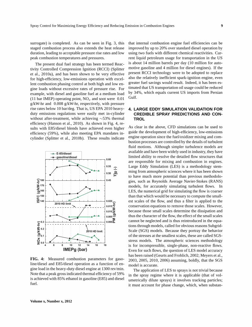
The present dual fuel strategy has been termed Reac-tivity Controlled Compression Ignition (RCCI) (Splitteret al., 2010a), and has been shown to be very effectivefor high-efficiency, low-emissions operation with excel-lent combustion phasing control at both high and low en-gine loads without excessive rates of pressure rise. Forexample, with diesel and gasoline fuel at a medium load(11 bar IMEP) operating point, NOx and soot were 0.01g/kW-hr and 0.008 g/kW-hr, respectively, with pressurerise rates below 10 bar/deg. That is, US EPA 2010 heavy-duty emissions regulations were easily met in-cylinderwithout after-treatment, while achieving∼53% thermalefficiency (Hanson et al., 2010). As shown in Fig. 4, re-sults with E85/diesel blends have achieved even higherefficiency (59%), while also meeting EPA mandates in-cylinder (Splitter et al., 2010b). These results indicate
4 6 8 10 12 14 16 180.0
0.1
0.2
0.3 0.000
0.005
0.010
0.015
0.020140
150
160
170
180 0.45
0.50
0.55
0.60
2010 HD limit
NO
x (
g/k
W-h
r)
IMEPg (bar)
2010 HD limit
PM
(g
/kW
-hr)
E-85/diesel
gasoline/diesel
ISF
C (
g/k
W-h
r)
ηg
(-)
FIG. 4: Measured combustion parameters for gaso-line/diesel and E85/diesel operation as a function of en-gine load in the heavy-duty diesel engine at 1300 rev/min.Note that a peak gross indicated thermal efficiency of 59%is achieved with 85% ethanol in gasoline (E85) and dieselfuel.
that internal combustion engine fuel efficiencies can beimproved by up to 20% over standard diesel operation byusing two fuels with different chemical reactivities. Cur-rent liquid petroleum usage for transportation in the USis about 14 million barrels per day (10 million for auto-motive gasoline and 4 million for diesel engines). If thepresent RCCI technology were to be adopted to replacealso the relatively inefficient spark-ignition engine, evengreater fuel savings would result. Indeed, it has been es-timated that US transportation oil usage could be reducedby 34%, which equals current US imports from PersianGulf.
4. LARGE EDDY SIMULATION VALIDATION FORCREDIBLE SPRAY PREDICTIONS AND CON-TROL
As clear in the above, CFD simulations can be used toguide the development of high-efficiency, low-emissionsengine operation since the fuel/oxidizer mixing and com-bustion processes are controlled by the details of turbulentfluid motions. Although simpler turbulence models areavailable and have been widely used in industry, they havelimited ability to resolve the detailed flow structures thatare responsible for mixing and combustion in engines.Large Eddy Simulation (LES) is a methodology stem-ming from atmospheric sciences where it has been shownto have much more potential than previous methodolo-gies, such as Reynolds Average Navier-Stokes (RANS)models, for accurately simulating turbulent flows. InLES, the numerical grid for simulating the flow is coarserthan that which would be necessary to compute the small-est scales of the flow, and thus a filter is applied to theconservation equations to remove those scales. However,because those small scales determine the dissipation andthus the character of the flow, the effect of the small scalescannot be neglected and is thus reintroduced in the equa-tions through models, called for obvious reasons Subgrid-Scale (SGS) models. Because they portray the behaviorof the stresses at the smallest scales, these are called SGS-stress models. The atmospheric sciences methodologyis for incompressible, single-phase, non-reactive flows.Even for such flows, the question of LES model accuracyhas been raised (Geurts and Frohlich, 2002; Meyers et al.,2003, 2005, 2010, 2006) assuming, boldly, that the SGSmodel is accurate.
The application of LES to sprays is not trivial becausein the spray regime where it is applicable (that of vol-umetrically dilute sprays) it involves tracking particles;it must account for phase change, which, when substan-
Volume x, Number x, 2012
10 Chigier et al.
tially influencing the flow, makes the flow compressible;and it must for some applications account for reactions.Even when introducing Favre averaging to render the LESequations for compressible flows similar to those for in-compressible flows, it is unclear that some of the assump-tions made in atmospheric sciences (e.g. isotropy at theKolmogorov scale, i.e. the smallest flow scale) are stillvalid. For these spray flows, additional to the SGS-stressmodel, one must provide SGS-flux models for mass andenthalpy. In the many applications where sprays are stud-ied in the context of reacting flows, it is necessary to intro-duce models other than representing the SGS-stress andSGS-fluxes for mass and enthalpy; these new models arefor the turbulent reaction rate. It is thus clear that theaddition of all these models, with corresponding assump-tions, makes the atmospheric-science LES potential ques-tionable for the more arduous spray problem. WithoutLES model validation, it is impossible to recommend LESfor routine spray prediction utilization. Some of the chal-lenges encountered in LES spray prediction have been al-ready outlined elsewhere (Bellan, 2000).
There is, however, an inherent difficulty in LES val-idation. Unlike in RANS where all scales are modeledusing the same model and grid convergence is attainedby gradually refining the grid, in the currently utilizedLES formulation, the large scales are exactly solved andonly the small scales are modeled. Thus, in the currentLES formulation, when refining the grid one no longerhas the same model because the SGS model is resolved-scale dependent. This fact has been recently highlightedfor two-phase flow formulations (Radhakrishnan and Bel-lan, 2010). Just as vexing a problem is the fact that fortwo-phase flow, LES computations are made by follow-ing computational drops instead of physical drops on theirtrajectories, but it is still unclear how one should choosethe number of computational drops to be accurately rep-resenting the physical drops. By rigorously defining com-putational drops (Okong’o and Bellan, 2004), it has beenshown that while the CPU simulation time decreases withdecreasing number of drops, so does the accuracy of thecomputation. A recent study using the same concept ofcomputational drops indicates that for large reductionsfrom physical to computational drops, a fine-grid LES isnot as accurate as a coarse-grid LES, beside being com-putationally more intensive (Radhakrishnan and Bellan,2011). This is attributed to the fact that a fine-grid LESused in conjunction with a reduction in the number of fol-lowed drops from the physical to a computational dropfield, implies that there is necessarily a smaller numberof drops in a computational cell than in Direct Numer-
ical Simulations (DNS); this aspect naturally influencesthe flow development and biases it from the true flow atthe LES resolution. Key to success seems to be matching,within a factor of two, the increase in the computationalcell volume in LES with the decrease in the number offollowed drops so that the LES computational cells haveapproximately the same number of drops as those in theDNS. This finding highlights the importance of obtain-ing drop-number experimental data in statistically-steadycombustion chambers or natural flows. Indeed, typicalKolmogorov scale values can be experimentally measuredin a flow, thus providing a reference from which the LESgrid can be chosen, but lack of drop number data currentlyprevents a cogent choice of the number of computationaldrops in LES calculations. Moreover, the results of thisstudy also show that the current, but unacknowledged,practice of increasing the number of computational dropsto obtain LES convergence in the same frame of mindas refining the LES grid to obtain grid-convergence, isflawed. Indeed, increasing number of particles to obtainsimulation convergence is borrowed from Monte-Carlosimulations in which the particles are a random field. Butin sprays, the drops do not represent a random field; theyare deterministic particles obeying trajectories influencedby drag and evaporation effects. This deterministic aspectis in conflict with the expectation of convergence with in-creasing number of drops.
Finally, it is well known that LES predictions can bequite different according to the choice of the SGS model.The questions are: Why are some models better than oth-ers? How should one choose among several possibilitiesthe best SGS model? Can one SGS model predict moreaccurately all quantities of interest in a spray application?If this is not the case, perhaps a good strategy would beto select quantities of interest, which we may call objec-tives and choose a SGS model best suited for those objec-tives very much like some investigators chose grids pro-viding optimal model accuracy (Meyers et al., 2006). Asystematic study following these directions of thought isstill missing.
Clearly, there is substantial work to be done to makeLES a truly predictive model for spray applications. Thequestions of grid independence and appropriate numberof computational drops should be augmented by otherimportant computational aspects, such as discretization-order dependence for the spatial representation. Indeed,without a robust LES methodology, it is impossible togive credence to simulations and compare them to ex-perimental data. If one can adjust model parameters toagree with data, this is no longer a predictive model, but
Atomization and Sprays

Spray Control for Maximizing Energy Efficiency and ReducingEmission in Combustion Engines 11
rather a descriptive model. However, predictive modelsare sought for applications because otherwise one cannotconstruct a control strategy. Once models are constructedthat are independent of the numerical part of the simula-tion, the next question is that of accuracy. The questionof accuracy relies on achieving a better understanding onthe strategy for choosing an appropriate SGS model.
Progress towards LES as a predictive tool has beenrecently made (Bose et al., 2010), but in the context ofincompressible flows and only for a single SGS model.Whether the same methodology remains valid for com-pressible flows, or for two-phase compressible flows withphase change, remains to be seen. Just as important isto determine the influence of the SGS models used, andwhether one model is better than others and if so, for whatreasons. Studies are currently conducted by the authorand collaborators to determine some of these crucial as-pects of LES validation.
5. SIMULATING NEAR NOZZLE FLOWS FROMFIRST PRINCIPLE
Understanding the physical details of the initial breakupof injected liquid fuel jets remains one of the outstandingproblems in multi-phase flows. While significant progresshas been made in the past years to study the primary at-omization region experimentally, using for example bal-listic imaging (Linne et al., 2006, 2005) and X-ray tech-niques (Wang et al., 2008, 2006), such analysis cannotyet provide the full 4-D data needed for a detailed anal-ysis. Numerical simulations, on the other hand, have thepotential to generate the needed comprehensive 4-D datasets. However, to become a tool that can be used compli-mentary to or even instead of experimental analysis, nu-merical simulations have to fulfill a list of requirements.These include governing equations derived ideally fromfirst principle, consistent code and solution verification,and validation if any type of modeling assumptions areintroduced.
Although tremendous progress has been made in thepast decade, current practice for simulations of the atom-ization process in combustion engines is still lacking inseveral of these requirements, most notably in the areas ofcode and solution verification. This is in part due to sev-eral yet open research questions in the area of numericalmathematics, but is driven primarily by limited availablecomputational resources.
The following sections are intended to outline the idealcase, being mindful of the fact that even if all open re-search questions on numerical methods can be answered
in the coming years, the necessary computational powerto perform true numerical experiments of the atomiza-tion process will be large and likely available only on thefastest supercomputers. Still, because of the continued in-crease in computational power, todays fastest supercom-puters will be commonplace machines within a decade, soadvances in methodology and numerical techniques needto be developed now in order to make good use of thesecomputational resources for the atomization communityin the near future.
5.1 Governing Equations
The first requirement is that the governing equations haveto be known. This, at first glance, seems trivial, sinceit is usually accepted that the combination of continuityequation, momentum equations augmented by a term de-scribing surface tension, and energy equation (abbrevi-ated as Navier-Stokes equations in the following) describethe flow encountered during primary atomization. How-ever, are these equations true from first principle in thecontext of an atomizing flow? The answer to this questionhas implications for validation and the predictive capabil-ities of simulations.
In single phase flows, the Navier-Stokes equations arecommonly accepted to be valid from first principle. How-ever, in liquid/gas flows, the phase interface representsa change in material properties, i.e. composition, den-sity, heat capacity, viscosity, and thermal conductivity,onscales associated with the mean free path of molecules.On such length scales, the continuum hypothesis inherentin the Navier-Stokes equations is no longer valid and onewould need to resort to a statistical mechanics descrip-tion. Enforcing the continuum hypothesis, i.e. limiting amesh Knudsen number, defined as the ratio of the meanfree path of molecules to the mesh spacing, to be muchsmaller than unity, turns the phase interface into a mate-rial discontinuity in the Navier-Stokes equations.
In non-atomizing liquid/gas flows, at least from a the-oretical point of view, this is not problematic, althoughit poses a number of numerical challenges. In atomizingflows, however, the length scale associated with the ac-tual break-up event goes to zero at the instant of topologychange. The associated Knudsen number thus becomeslarge and the Navier-Stokes equations are no longer valid.From a first principle point of view, the dynamics at themoment of topology change and for a short time beforeand after thus have to be treated using a statistical me-chanics approach which includes the then dominant van-der Waals forces. In the absence of a statistical mechanics
Volume x, Number x, 2012

12 Chigier et al.
treatment a model has to be introduced for the details ofthe topology change. The use of such a model impliesthat the governing equations are no longer derived fromfirst principle.
It remains an open question, of whether a treatmentof the phase interface as a material discontinuity usingthe Navier-Stokes equations is a valid approximation foratomization of liquid jets in engine applications. If thefinal stages of individual breakup events are dominatedby instabilities represented by the Navier-Stokes equa-tions, e.g. shear layer, Rayleigh-Taylor, or capillary insta-bilities, the solutions to the Navier-Stokes equations canbe expected to capture the correct atomization physics.If the breakup mechanism occurs via the formation andbreakup of thin liquid sheets, the incorporation of a sta-tistical mechanics treatment to describe the sheet ruptureis likely required. In internal combustion engines, bothtype of breakup mechanisms are present: sheet like struc-tures generated at the leading tip of the jet due to start-up vortices, and ligament type breakup from the liquidcore (Herrmann, 2011; Shinjo and Umemura, 2010, 2011;Umemura, 2011).
5.2 Numerical Methods
Providing an overview of available numerical methods tosolve for liquid/gas flows in the continuum limit is be-yond the scope of this contribution. Instead the readeris referred to available overview articles in the literature(Gorokhovski and Herrmann, 2008; Scardovelli and Za-leski, 1999). Instead, this section is intended to point outsome of the numerical challenges a chosen method hasto address to be viable for predictive atomization simula-tions.
The guiding principle for choosing or designing a nu-merical method should be that numerical discretizationerrors must be clearly differentiable from modeling errorsinherent in the governing equations. Any mixing of thetwo is unacceptable from a fundamental point of view,since it precludes solution verification and thus cannotgive a fair evaluation of the error and applicability of themodel itself. Unfortunately, it remains common practiceto violate this principle and either couple physical model-ing parameters directly to numerical parameters like gridspacing, or accept modeling restrictions that limit howsmall grid spacings can become.
An example of the former is the topology changemodel inherent in fixed grid methods. The topologychange model, which is a necessity for simulations basedon the continuum Navier-Stokes equations, typically con-
sists of a breakup length scale, such that if two opposinginterface segments approach each other closer, topologychange is introduced. In fixed grid methods like the levelset method or volume of fluid, the breakup length scaleis equal to the local grid spacing and thus is a numericaland not a modeling parameter. An example of the latterare standard Lagrangian point particle spray models, al-though non-violating methods have been proposed in thepast (Garg et al., 2007, 2009).
From a theoretical point of view, a chosen numeri-cal method has to fulfill three requirements: it has to beconsistent, i.e. the numerical approximation approachesthe governing PDEs under grid and time step refinement,it has to be stable, i.e. the numerical solution remainsbounded, and it has to converge, i.e. the numerical solu-tion approaches the solution of the governing PDEs un-der grid and time step refinement. For linear, well posedinitial value problems, convergence is guaranteed if themethod is both consistent and stable, however, in how farthis is true for the non-linear Navier-Stokes equations is anot fully answered question.
A further challenge is that the standard proof for con-sistency of a numerical method relies on Taylor series ex-pansions and the requirement that higher order derivativesremain bounded. This is obviously not the case at thephase interface, since it is a material discontinuity andspatial derivatives become infinite. Thus appropriate nu-merical methods either have to provide for a split treat-ment of the two phases coupled via a separate treatmentat the phase interface by for example explicitly enforcingthe appropriate Rankine-Hugoniot jump conditions, or re-sort to integral forms of the governing equations.
It should be pointed out that for many numerical meth-ods currently in use for liquid/gas flows, the formal proofof consistency, stability, and convergence has not beenachieved and thus requires further research. Strictlyspeaking, finite difference methods, for example, un-avoidably incur a zeroth-order error in the infinity normat the phase interface, since even the smallest error in theposition of the interface causes an intermittent O(1) errorin material properties due to their discontinuous nature.The question then becomes whether this inability to con-verge under grid refinement in the infinity norm impactsthe perhaps more relevant one- and two-norms and howthe error propagates into the rest of the computational do-main polluting the solution there. By similar arguments,finite volume methods incur at least a first-order error incells containing the phase interface and are likely sub-ject to the same error propagation and pollution behavior.Even though it is common practice to blend out errors
Atomization and Sprays

Spray Control for Maximizing Energy Efficiency and ReducingEmission in Combustion Engines 13
at discontinuities when analyzing the convergence behav-ior of numerical methods, whether this is appropriate foratomizing flows, where the atomization process is dom-inated by the dynamics at the phase interface is an openquestion.
5.3 Code Verification
Code verification is an often overlooked key requirementfor a predictive simulation tool. Its goal is to ensure thatthe consistent, stable, and convergent numerical solutiontechniques of the governing equations are implemented inthe software correctly. To check this, the obtained numer-ical solution has to follow the theoretical error conver-gence behavior that can be derived from the theoreticalproof of convergence of the numerical method.
The major challenge is that this requires an exact solu-tion to the governing equations in order to be able to cal-culate the error of the discrete solution. While exact solu-tions to the Navier-Stokes equations are known, these, forthe most part, rely on the introduction of simplificationsthat deactivate terms in the governing equations. Thesesimple exact solutions are thus not sufficient for code ver-ification purposes since they cannot test the deactivatedterms. In fact, to the knowledge of the author, there ex-ists no exact solution to the three-dimensional unsteadyNavier-Stokes equations including phase interfaces thathas every term in the equations non-zero. Without furtherresearch in this area, using exact solutions to the Navier-Stokes equations can thus be at best a necessary, but notsufficient code verification exercise.
An alternative to using exact solutions to the Navier-Stokes equations is to use the method of manufacturedsolution (Oberkampf and Blottner, 1998; Roache, 2002;Roy, 2005). The key idea is to allow an extension of thegoverning equations by adding source terms to the equa-tions. Then, instead of trying to find an exact solutionto the governing equations, one reverses the process andchooses an exact solution and derives the source termsthat would result in the chosen exact solution. Becausethe exact solution is chosen, it can be arbitrarily complexand have each term in the governing equations non-zero,i.e. active. Since code verification is a mere numericalmathematical exercise, the chosen exact solution need notbe a physical one. It in fact is often beneficial to chooseexact solutions that are unphysical to thoroughly test allimplementation terms.
The method of manufactured solution has proven verysuccessful in code verification of single phase solvers,however extension of the technique to liquid/gas flows
with discontinuous phase interfaces are areas of active re-search with some promising initial results (Brady et al.,2011).
Established reference numerical solutions are oftenused for code verification as well. From a fundamentalpoint of view this is somewhat unsatisfactory, since it re-lies on the results of another simulation framework thatin itself might be prone to error. The requirement thatit be an established solution provides some level of com-munity check, however, a mathematical proof as availablethrough exact or manufactured solutions is always prefer-able.
Finally, it is important to note that code verificationis a continuous process. It is in principle not sufficientto perform it ones in the evolution process of a code andthen simply refer to that exercise as proof of code verifi-cation. Any time any part of a simulation infrastructure ischanged, code verification has to be performed anew, ide-ally in the form of periodic regression testing. Althoughcurrently not the norm, a statement to the effect that com-prehensive code verification has been passed immediatelypreceding the generation of any simulation result shouldbe included in all publications of numerical results.
5.4 Solution Verification
Solution verification refers to the exercise that ensuresthat an obtained numerical solution to the governing equa-tions is not unduly impacted by numerical discretizationerrors both in space and time. It can be done by perform-ing a series of simulations using varying grid and timestep sizes. Unlike code verification, an exact or estab-lished solution is typically not available for comparisonand definition of an error norm. So when can a simula-tion be considered unimpeded of numerical error? Thekey is to demonstrate that the numerical solution is in theasymptotic convergence region. Note that the achievable,so-called observed order of accuracy is usually smallerthan the formal order of accuracy that Taylor series ex-pansions can provide.
Roache (1994) established a formal method of re-porting solution verification results by introducing theso-called grid convergence index (GCI). It is based onRichardson-extrapolation and includes a formal quanti-tative measure of whether a solution is in the asymp-totic range. Although the GCI in principle can establishwhether a solution is verified, its application to liquid/gasflows with phase interfaces is complicated by the fact thatthe phase interface is a discontinuity in the continuumlimit. Further research is needed of how to consistently
Volume x, Number x, 2012

14 Chigier et al.
incorporate the phase interface discontinuity in the GCIanalysis. Among the open questions is if and how er-rors introduced at the phase interface influence the sim-ulation results away from the phase interface. As men-tioned above, some numerical methods are by definitionprone to zeroth- or first-order errors at the phase interface.While it is believed that such methods are not dominatedby these errors away from the interface, it remains to beconclusively proven for the case of atomizing flows.
Strictly speaking solution verification has to be per-formed for each simulation anew, even if initial andboundary conditions do not significantly change. Thusalthough the common practice of establishing a requiredresolution either by physical arguments or by solutionverification of a single operating condition is understand-able from a simulation cost perspective, it is not sufficient.Such arguments can only be made to give guidance on thelikely necessary resolution, which then still has to be ver-ified. Using the guidance, this can then be done in a costeffective manner by performing grid/time step coarseninginstead of refinement.
As for code verification, a major complication for so-lution verification is the typical inherent mixing of model-ing and numerical parameters. As a further example, con-sider the surface tension force. It is active only at the loca-tion of the phase interface, so mathematically is describedby a delta function affixed to the phase interface. Puredelta functions are notoriously difficult to treat in numer-ical methods, so it is common practice in many numericalmethods to spread the surface tension force across a smallnumber of cells in the front normal direction (Brackbillet al., 1992; Sussman et al., 1994). The associated thick-ness of the surface tension force application region thenin fact becomes a modeling parameter. If, this modelingparameter is directly coupled to the local grid spacing atthe phase interface, a grid refinement study, as is requiredfor verification, has the unattended consequence of mod-ifying the used model parameter and thus the employedmodel. It thus becomes impossible to differentiate be-tween modeling errors and numerical errors.
It should be noted that Large Eddy Simulations (LES)face a very similar predicament, in that the implicit andexplicit filter widths are usually coupled to the local gridspacing as well. In both cases the argument is commonlymade that because grid refinement changes the employedmodel, simulation verification is in principle not possi-ble and in fact not necessary, because refining the gridwill approach the non-modeled state, in the case of LES adirect numerical simulation, and for phase interfaces themathematical delta function. Albeit convenient, this line
of argument is inconsistent. To ascertain the validity andquality of a model, it is imperative to be able to knowthe models answer on its own merit, i.e. unimpeded bynumerical errors. For surface tension models using finitewidths, this means that the width of the delta function ap-proximation should not be coupled to the mesh size andhas to be kept constant under grid refinement. For thetopology change model discussed earlier, a similar argu-ment holds that the breakup length scale has to be decou-pled from the local grid spacing.
5.5 Validation
The purpose of validation is to ensure that the correct gov-erning equations for the analyzed physical problem aresolved. It can only be performed after successful codeverification and only using numerical results that have un-dergone solution verification. If these two pre-requisitesare fulfilled and the governing equations are derived fromfirst principle, then, strictly speaking, validation is notre-quired, since it can only check the validity of the govern-ing equations, which are valid from first principle.
In practical simulation tools for atomization basedon the Navier-Stokes equations alone, there does unfor-tunately remain a need to validate the solver, becausethe first principle assumption of the governing equationsbreaks down near the moment of topology change and atopology change model has to be introduced. In addition,if the governing equations are modified to allow a finitewidth of the phase interface on the continuum scale thevalidity of these modified equations has to confirmed.
The challenge for validating simulation tools for atom-izing flows lies in the limited available experimental val-idation data. With few exceptions, experimental data isavailable only in regions far away from the injector, con-sists of integral quantities, and does not fully define allboundary or initial conditions. There is in fact a severelack of quality experimental data useable for validationand significant efforts should be made to establish thesedata sets in the near future.
Another challenge lies in the fact that although simula-tions are deterministic in nature, small changes in bound-ary and initial conditions can have different outcomes. Assuch a validation simulation has to be performed for anensemble of boundary and initial conditions that repre-sent the experimental conditions and it is the ensembleaverages that have to be compared.
While quantitative agreement of simulation data withintegral quantities from experiments is a necessary con-dition for validation, it is not sufficient to claim a vali-
Atomization and Sprays

Spray Control for Maximizing Energy Efficiency and ReducingEmission in Combustion Engines 15
dated tool, since the good agreement might simply be theresult of fortuitous modeling error cancellation. Further-more it must be stressed that reproducing experimentallyobtained results while adjusting model parameters is notvalidation. Validation simulations should be performedwithout any knowledge of the experimental results, ex-cept for the boundary and initial conditions. Only aftercode and solution verification should the numerical re-sults be quantitatively compared to the experimental re-sults. If at that stage, a discrepancy is found and the modelis adjusted, the simulation is no longer a validation and anew validation case has to be performed.
Finally, if modeling constants are not constants butrequire adjustments using tuning simulations, validationcases have to span the entire operating condition space ofthe target application for which the simulation tool is tobe used.
5.6 Prediction
Prediction is the generation of simulation results forwhich no experimental data is available. For atomiza-tion simulations, this can have a two-fold meaning. Onthe one hand, and this is the traditional view, a predictionsimulation can generate results for operating conditionsfor which no data is yet available. Can these results betrusted? If code and solution verification have been suc-cessfully performed and the governing equations are validfrom first principle, then the simulation results are as goodif not superior to a physical experiment. If the governingequations are not derived from first principle and model-ing is involved, then the prediction simulations operatingconditions have to be within the validation domain of op-erating conditions. In some sense a prediction simulationthen turns into an interpolation in the validated operatingcondition space.
On the other hand, one can use a prediction simulationto study details of physical processes that are not acces-sible to experimental analysis. This can happen for op-erating conditions, for which integral experimental datais available and reproduced by the simulation. An in-teresting question is whether tuning is allowed in sucha simulation to reproduce the integral experimental dataor whether the experimental data has to be reproduced ina true validation simulation. The answer to this questiondepends on the amount of modeling, i.e. how far awayfrom first principle the governing equations are, and whatphysical processes are to be studied. Thus, an answerlikely cannot be generalized. It is however this secondcategory where simulations will have their largest impact
in the coming years, especially in conjunction with lat-est experimental techniques for the primary atomizationregion that can provide spot validation data of the phaseinterface geometry and dynamics.
6. SUMMARY AND OUTLOOK
Spray combustion will remain as an important sourceof energy for many more years. Although further largeimprovements in energy efficiency cannot be obtainedthrough perfecting the fuel delivery methods, additionaldevelopment is warranted. The greatest benefits can berealized in pollutant emissions reduction. As outlinedin this review, innovations in spray diagnostics and es-pecially in optical methods have allowed acquisition ofnecessary information that has led to insights and a betterunderstanding of these very complex combustion sprayflows. Early measurements of basic spray parameterswere a necessary start in this process of understandingand innovation. However, spray flows associated withcombustion systems represent one of the most complexfluid mechanics problems. These flows involve turbulentliquid breakup mechanisms, gas phase turbulence inter-action with the dispersed phase, vaporization, and chem-ical reaction. Basic drop size measurements are far fromsufficient in defining these complex conditions. With in-creasing atomization pressures and decreasing nozzle ori-fice diameters come much greater complexity and diffi-culty when attempting to measure or otherwise charac-terize the flow within and near the exit of the injectors.There is currently great interest in the effects of cavita-tion on near-exit atomization. There is also growing in-terest in the possibility of flow swirl initiated within theinjector and its subsequent effect on the spray formationand dispersion. These phenomena are extremely difficult,if not impossible, to measure or even to observe experi-mentally due to the small scales, turbulent, deformed liq-uid surfaces, high droplet and gas phase velocities, andhigh pressures involved. Observations of scaled-up mod-els have been used but questions arise as to their validityin describing the conditions at actual spray orifice sizesand conditions (Balewski, 2009). Future developmentsincorporating significant innovations in the diagnosticsand modeling will be required to extract information onthese small-scale, but important flows.
At this stage, it appears that modeling efforts have agreater chance of succeeding in predicting and describinginternal flow features. It is very unlikely that measure-ments can be made within these very small orifices at thepressures and velocities that currently prevail. Clearly,
Volume x, Number x, 2012

16 Chigier et al.
there needs to be a greater effort in integrating experi-mentation and modeling to advance our understanding inthe future development of these very complex combustionsystems.
However, a number of theoretical challenges remain tomake simulations predictive and a tool to be used for dis-covery on par with experimental methods. A remaininglimitation is the available computational resources.
The requirement of code verification, the need for en-semble average solution verified validation, and the ne-cessity for ensuring the predictive aspects of simulationsdrastically increases the computational cost. Although,using todays computational resources, single non-verifiedsimulations of the atomization process in IC engines arepossible, following a stringent procedure just outlinedadds orders of magnitude more cost. However, with thecontinued fast paced growth of supercomputers, the re-quired computational power will become available in thenext one to two decades. At that point, and perhaps sig-nificantly earlier, simulations will be able to enhance andperhaps replace experiments as the preeminent scientificdiscovery tool for atomizing flows.
ACKNOWLEDGEMENTS
Part of this work was carried out at the Jet Propulsion Lab-oratory, California Institute of Technology, under a con-tract with the National Aeronautics and Space Adminis-tration. Government sponsorship is acknowledged.
REFERENCES
Abbott, D., Keeping the energy debate clean: How do we sup-ply the world’s energy needs?,Proc. of IEEE, vol. 98, no. 1,2010.
Bachalo, W. D., A method for measuring the size and velocity ofspheres by dual beam scatter interferometry,Applied Optics,vol. 19, no. 3, 1980.
Bachalo, W. D., Spray characterization: Are we making anyprogress?,ILASS Americas 17th Annual Conference, Wash-ington DC, 2004.
Bachalo, W. D. and Houser, M. J., Phase doppler spray analyzerfor simultaneous measurements of drop size and velocity dis-tributions,Optical Engineering, vol. 23, no. 5, 1984.
Bachalo, W. D. and Houser, M. J., Spray drop size and veloc-ity measurements using the phase/doppler particle analyzer,Proceedings of the Third International Conference on LiquidAtomization and Spray Systems, 1985.
Balewski, B., Experimental Investigation of the Influence of
Nozzle-Flow Properties on the Primary Spray Breakup, PhDthesis, TU Darmstadt, 2009.
Bellan, J., Perspectives on large eddy simulations for sprays: Is-sues and solutions,Atom. Sprays, vol. 10, pp. 409–425, 2000.
Bolszo, C. D., Rohani, M., Narvaez, A. A., Dunn-Rankin, D.,McDonell, V. G., and Sirignano, W. A., Breakup of water-in-oil emulsions in liquid jets and conical sheets,ILASS Ameri-cas 22nd Annual Conference, Cincinnati, OH, 2010.
Bose, S. T., Moin, P., and You, D., Grid-independent large-eddy simulation using explicit filtering,Phys. Fluids, vol. 22,no. 105103, pp. 1–11, 2010.
Brackbill, J. U., Kothe, D. B., and Zemach, C., A contin-uum method for modeling surface tension,J. Comput. Phys.,vol. 100, pp. 335–354, 1992.
Brady, P., Herrmann, M., and Lopez, J., Code verification by themethod of manufactured solutions for two-phase flows withsharp interfaces,ILASS Americas 23rd Annual Conference onLiquid Atomization and Spray Systems, Ventura Beach, CA,2011.
Cai, W., Powell, C. F., Yue, Y., Narayanan, S., and Wang, J.,Quantitative analysis of highly transient fuel sprays by time-resolved x-radiography,Applied Physics Letters, vol. 83,no. 8, 2003.
Dodge, L. G., Change of calibration of diffraction-based particlesizers in dense sprays,Optical Engineering, vol. 23, no. 4,1984.
Geurts, B. J. and Frohlich, J., A framework for predicting ac-curacy limitations in large-eddy simulation,Phys. Fluids,vol. 14, no. 6, pp. L41–L44, 2002.
Garg, R., Narayanan, C., Lakehal, D., and Subramaniam, S., Ac-curate numerical estimation of interphase momentum trans-fer in lagrangian–eulerian simulations of dispersed two-phaseflows, International Journal of Multiphase Flow, vol. 33,no. 12, pp. 1337–1364, 2007.
Garg, R., Narayanan, C., and Subramaniam, S., A numericallyconvergent lagrangian–eulerian simulation method for dis-persed two-phase flows,International Journal of MultiphaseFlow, vol. 35, no. 4, pp. 376–388, 2009.
Gorokhovski, M. and Herrmann, M., Modeling primary atom-ization,Annual Review of Fluid Mechanics, vol. 40, no. 1, pp.343–366, 2008.
Hanson, R., Reitz, R. D., Splitter, D., and Kokjohn, S., An ex-perimental investigation of fuel reactivity controlled PCCIcombustion in a heavy-duty engine,SAE Paper, no. 2010-01-0864, pp. SP–2279, 2010.
Herrmann, M., 2011. On simulating primary atomization usingthe refined level set grid method, accepted for publication inAtom. Sprays.
Heuer, M. and Leschonski, K., Results obtained with a new in-strument for the measurement of particle size distributions
Atomization and Sprays

Spray Control for Maximizing Energy Efficiency and ReducingEmission in Combustion Engines 17
from diffraction patterns,Part. Charact., pp. 7–13, 1985.
Heywood, J. B.,Internal Combustion Engine Fundamentals,McGraw Hill, 1988.
Hirleman, E. D., On-line calibration technique for laser diffrac-tion droplet sizing instruments,28th Int. Gas Turbine Con-ference, no. 83–GT–232, Am. Soc. Mech. Eng., New York,1983.
Kastengren, A. L., Powell, C. F., Wang, Y., Im, K.-S., and Wang,J., X-ray radiography measurements of diesel spray structureat engine-like ambient density,ILASS Americas 21st AnnualConference, Orlando, FL, 2008.
Kokjohn, S., Hanson, R., Splitter, D., and Reitz, R. D., Exper-iments and modeling of dual fuel HCCI and PCCI combus-tion using in-cylinder fuel blending,SAE paper, no. 2009-01-2647, 2009.
Kokjohn, S. L. and Reitz, R. D., A modeling study of chargepreparation in an HCCI engine using a variable pressure pulse(VPP) injection system and optimized PRF blends,Proc. Int.Conf. Liq. Atom. Spray Syst., Vol. 11, Vail, CO, 2009.
Linne, M., Paciaroni, M., Hall, T., and Parker, T., Ballistic imag-ing of the near field in a diesel spray,Experiments in Fluids,vol. 40, pp. 836–846, 2006.
Linne, M. A., Paciaroni, M., Gord, J. R., and Meyer, T. R., Bal-listic imaging of the liquid core for a steady jet in crossflow,Applied Optics, vol. 44, no. 31, pp. 6627–6634, 2005.
Meyers, J., Geurts, B. J., and Baelmans, M., Database analy-sis of errors in large-eddy simulation,Phys. Fluids, vol. 15,no. 9, pp. 2740–2755, 2003.
Meyers, J., Geurts, B. J., and Baelmans, M., Optimality of thedynamic procedure for large-eddy simulations,Phys. Fluids,vol. 17, no. 045108, pp. 1–9, 2005.
Meyers, J., Meneveau, C., and Geurts, B. J., Error-landscape-based multiobjective calibration of the smagorinsky eddy-viscosity using high-reynolds-number decaying turbulencedata,Phys. Fluids, vol. 22, no. 125106, pp. 1–14, 2010.
Meyers, J., Sagaut, P., and Geurts, B. J., Optimal model parame-ters for multi-objective large eddy simulations,Phys. Fluids,vol. 18, no. 095103, pp. 1–12, 2006.
Oberkampf, W. L. and Blottner, F. G., Issues in computationalfluid dynamics code verification and validation,AIAA J.,vol. 36, no. 5, pp. 687–695, 1998.
Okong’o and Bellan, J., Consistent large eddy simulation ofatemporal mixing layer laden with evaporating drops. part 1:Direct numerical simulation, formulation and a priori analy-sis,J. Fluid Mech., vol. 499, pp. 1–47, 2004.
Park, S. W. and Reitz, R. D., Numerical study on the low emis-sion window of homogeneous charge compression ignitiondiesel combustion,Combust. Sci. and Tech., vol. 179, no. 11,pp. 2279–2307, 2007.
Ra, Y. and Reitz, R. D., A reduced chemical kinetic model for ic
engine combustion simulations with primary reference fuels,Comb. Flame, vol. 155, pp. 713–738, 2008.
Radhakrishnan, S. and Bellan, J., Effect of grid spacing inlarge-eddy simulation of evaporating drops in a mixing layer,ILASS Americas 22nd Annual Conference, Cincinnati, OH,2010.
Radhakrishnan, S. and Bellan, J., Influence of computationaldrop representation in les of a droplet-laden mixing layer,ILASS Americas 23rd Annual Conference on Liquid Atom-ization and Spray Systems, Ventura Beach, CA, 2011.
Roache, P. J., Perspective: A method for uniform reporting ofgrid refinement studies,J. Fluids Eng., vol. 116, 1994.
Roache, P. J., Code verification by the method of manufacturedsolutions,J. Fluids Eng., vol. 124, no. 1, pp. 4–10, 2002.
Roy, C. J., Review of code and solution verification proce-dures for computational simulation,Journal of Computa-tional Physics, vol. 205, no. 1, pp. 131–156, 2005.
Sankar, S. V., Buermann, D. H., and Bachalo, W. D., Simultane-ous measurements of droplet size, velocity, and temperaturein a swirl-stabilized spray flame,7th Int’l. Symp. on the Appl.of Laser Techniques to Fluid Mechanics, Lisbon, Portugal,1994.
Sankar, S. V., Robert, D. M., and Bachalo, W. D., Detailed char-acterization of fuel droplets in a spray flame using an inte-grated phase doppler/rainbow refractometer system,Sympo-sium on Spray Systems Technology, International MechanicalEngineering Congress, ASME Winter Annual Meeting, Dal-las, Texas, 1997.
Scardovelli, R. and Zaleski, S., Direct numerical simulationof free-surface and interfacial flow,Annu. Rev. Fluid Mech.,vol. 31, pp. 567–603, 1999.
Sedarsky, D. L., Gord, J., Carter, C., Meyer, T. R., and Linne,M., Fast-framing ballistic imaging of velocity in an aeratedspray,Optics Letter, vol. 34, no. 18, 2009.
Sedarsky, D. L., Paciaroni, M. E., Linne, M. A., Gord, J. R., andMeyer, T. R., Velocity imaging for the liquid–gas interfaceinthe near field of an atomizing spray: Proof of concept,OpticsLetter, vol. 31, pp. 906–908, 2006.
Shinjo, J. and Umemura, A., Simulation of liquid jet primarybreakup: Dynamics of ligament and droplet formation,In-ternational Journal of Multiphase Flow, vol. 36, no. 7, pp.513–532, 2010.
Shinjo, J. and Umemura, A., Surface instability and primaryatomization characteristics of straight liquid jet sprays, In-ternational Journal of Multiphase Flow, vol. 37, no. 10, pp.1294–1304, 2011.
Smallwood, G. J., Gulder, O. L., and Snelling, D. R., The struc-ture of the dense core region in transient diesel sprays,Proc.Combust. Inst., vol. 25, pp. 371–379, 1994.
Splitter, D. A., Hanson, R., and Reitz, R. D., High efficiency,
Volume x, Number x, 2012
18 Chigier et al.
low emissions reactivity controlled combustion through useof a fuel additive,SAE 2010 Powertrains Fuels & LubricantsMeeting, no. 10FFL-0045, San Diego, CA, 2010a.
Splitter, D. A., Hanson, R. M., Kokjohn, S. L., and Reitz, R.,Improving engine performance by optimizing fuel reactivityin a dual-fuel PCCI strategy,THIESEL 2010 Conference onThermo-and Fluid Dynamic Processes in Diesel Engines, Va-lencia, Spain, 2010b.
Sussman, M., Smereka, P., and Osher, S., A level set methodfor computing solutions to incompressible two-phase flow,J.Comput. Phys., vol. 114, p. 146, 1994.
Swithenbank, J., Beer, J. M., Taylor, D., Abbot, D., and Mc-Creath, C. G., Experimental diagnostics in gas phase com-bustion systems,Progress in Astronautics and Aeronautics,vol. 53, pp. 421–447, 1977.
Trolinger, J. D. and Bachalo, W. D., Particle field diagnos-tics systems for high temperature/pressure environments,EPA/ERDA Symposium on High Temperature/Pressure Par-ticulate Control, Washington DC, 1977.
Trolinger, J. D. and Bachalo, W. D., Optical diagnostics in com-bustion research,Conference on Laser and Electro-OpticalSystems, San Diego, CA, 1980.
Umemura, A., Self-destabilizing mechanism of a laminar invis-cid liquid jet issuing from a circular nozzle,Physical ReviewE, vol. 83, no. 4, 2011.
Wang, Y., Liu, X., Im, K.-S., Lee, W.-K., Wang, J., Fezzaa, K.,Hung, D. L. S., and Winkelman, J. R., Ultrafast X-ray studyof dense-liquid-jet flow dynamics using structure-trackingvelocimetry,Nat Phys, vol. 4, no. 4, pp. 305–309, 2008.
Wang, Y. J., Im, K.-S., Fezzaa, K., Lee, W. K., Wang, J.,Micheli, P., and Laub, C., Quantitative X-ray phase-contrastimaging of air-assisted water sprays with high Weber num-bers,Applied Physics Letters, vol. 89, no. 15, pp. 151913–151913, 2006.
Atomization and Sprays