standard mission assurance requirements · the developer shall direct the suspensi on of any work...
TRANSCRIPT

320-MAR-1001D
Standard Mission Assurance Requirements
Requirements, Acronym List, DIDs, DID List, MAR Response Form,
and Tailoring Table
Code 320 Controlled Document
Release Date: 02/08/2012
National Aeronautics and Space Administration
Goddard Space Flight Center Greenbelt, Maryland

320-MAR-1001D Standadrd Mission Assurance Requirements (MAR) p. 2/114
Check the OSSMA Controlled Documents List at: https://ossmacm.gsfc.nasa.gov/index.cfm to verify that this is
the correct version prior to use.
This is a Code 320 Mission Support Division document controlled under the Code 300 configuration management system. Requests for changes to this document are to be submitted electronically at https://ossmacm.gsfc.nasa.gov/index.cfm. Document Approval Signature: Original Signed by: Michael P. Kelly Date: Chief, Mission Assurance Division
_02/08/2012 _
Code 320

320-MAR-1001D Standadrd Mission Assurance Requirements (MAR) p. 3/114
Check the OSSMA Controlled Documents List at: https://ossmacm.gsfc.nasa.gov/index.cfm to verify that this is
the correct version prior to use.
Table of Contents
1. Applicability……………………………………………………………………………………………… 4 2. Change Control Board (CCB)……………………………………………………………………………..4 3. Guidelines for Use………………………………………………………………………………..………. 4
3.1. Out-of-House Project MAR…………………………………………………………………………. 4 3.2 Project-level MAR…………………………………………………………………………………….4
Appendix 1. Mission Assurance Requirements……………………………………………………………... 6 Appendix 2. Acronym List………………………………………………………………………………… 19 Appendix 3. Data Item Descriptions………………………………………………………………………. 21 Appendix 4. MAR Response Form…………………………………………………………………………91 Appendix 5. Data Item Description List…………………………………………………………………… 98 Appendix 6. Tailoring Table……………………………………………………………………………… 104 Change History Log……………………………………………………………………………………….. 110

320-MAR-1001D Standadrd Mission Assurance Requirements (MAR) p. 4/114
Check the OSSMA Controlled Documents List at: https://ossmacm.gsfc.nasa.gov/index.cfm to verify that this is
the correct version prior to use.
1. Applicability This document is to be used for developing a Mission Assurance Requirements (MAR) document for contracts related to GSFC managed projects. The baseline requirements of this document are intended to meet those of a Class B out-of-house mission. A tailoring table is included that contains requirements and recommendations for modifying the requirements to a Class A, C, or D mission. The document can serve as a guide to develop a project-level MAR. The project-level MAR can be used to provide a high level perspective on assurance requirements that will be addressed in an out-of-house project’s MAR or an in-house project’s mission assurance implementation plan (MAIP). 2. Configuration Control Board (CCB) The Code 320 deputy division chief shall chair the Configuration Control Board (CCB) for this document. The CCB will consist of the deputy division chief and technical and administrative personnel necessary for recommending the disposition of configuration change requests (CCRs). The deputy division chief shall process CCRs per 300-PG-1410.2.1. In processing CCRs, the deputy division chief shall:
− Request support from technical and administrative personnel in formulating a disposition − Present recommended dispositions to the Code 320 division chief for approval − Prepare the signature folder with supporting documentation for the Code 300 configuration manager
The Code 320 division chief shall indicate approval of the document and CCRs by signature. The Code 320 division office shall maintain CCB records. 3. Guidelines for Use The Code 320 CSO (Chief Safety and Mission Assurance Officer) prepares the project MAR using the contents of this document’s appendices and project requirements. The MAR should conform to the project’s configuration management system requirements. The MAR becomes a project-controlled document after its approval by Code 300 with the expectations that the CSO is a member of the CCB that controls changes to it and that the CSO will inform Code 320 management of significant changes. 3.1. Out-of-House Project MAR The MAR will be part of the project procurement packages for spacecraft, instruments, and subassemblies. The MAR will consist of a narrative section derived from Appendix 1, an acronym list from Appendix 2, data item descriptions (DIDs) from Appendix 3, and the MAR response form from Appendix 4. Appendix 5 can be used to prepare a list of DIDs for the project’s contract deliverable requirements list (CDRL). The contents of Appendices 1, 2, 3, and 4 are generally suitable for a Class B mission. Included in the appendices are notations to the CSO in bold italics that indicate elements that must or may be tailored. For example, certain areas require tailoring for specific projects, such as launch vehicle and range or the type of equipment being procured. In other cases, tailoring is optional, such as whether the GSFC parts engineer is a voting or nonvoting member of the developer’s parts control board. Note that the language in bold italics is not to appear in the MAR. Since Appendices 1 and 3 are intended to meet the requirements of a Class B mission, it is expected that the CSO will tailor elements of Appendices 1 and 3 for a Class A, C, or D mission. Appendix 6 identifies areas that require tailoring and others that may be tailored. The contents of Appendix 2 are the acronyms in Appendix 1. Modifications to the contents of Appendices 1 or 3 made during project MAR development may need to be reflected in the use of Appendix 2.

320-MAR-1001D Standadrd Mission Assurance Requirements (MAR) p. 5/114
Check the OSSMA Controlled Documents List at: https://ossmacm.gsfc.nasa.gov/index.cfm to verify that this is
the correct version prior to use.
3.2 Project-level MAR The CSO may determine that it is reasonable to prepare a project-level MAR to delineate the high level safety and mission assurance requirements that apply to a project. The general recommendation is that Appendices 1 and 2 can be used for this purpose, with references to the DIDs removed and references to applicable GSFC GPRs, PGs, WIs, and standards added.
320-MAR-1001D Standadrd Mission Assurance Requirements (MAR) p. 6/114
Check the OSSMA Controlled Documents List at: https://ossmacm.gsfc.nasa.gov/index.cfm to verify that this is
the correct version prior to use.
Appendix 1. Mission Assurance Requirements Section 1. GENERAL 1.1 Systems Safety and Mission Assurance Program The developer shall prepare, document, and implement a Mission Assurance Implementation Plan (MAIP) in accordance with the Statement of Work (DID 1-1). The MAIP shall cover:
- All flight hardware and software that is designed, built, or provided by the developer and its subcontractors or furnished by the government, from project initiation through launch and mission operations
- The ground system that interfaces with flight equipment to the extent necessary to assure the integrity and safety of flight items
- The ground data system 1.2 Management The developer shall designate a manager for assurance activities. The assurance manager shall not be responsible for project costs and schedules other than those pertaining to assurance activities. The manager shall have direct access to management that is independent of project management and functional freedom and authority to interact with all elements of the project. 1.3 Requirements Flowdown The developer shall apply the requirements in this document to subcontractors and suppliers to the extent necessary to ensure that the delivered product meets performance requirements. 1.4 Suspension of Work Activities The developer shall direct the suspension of any work activity that presents a hazard, imminent danger, or future hazard to personnel, property, or mission operations resulting from unsafe acts or conditions that are identified by inspection, test, or analysis. 1.5 Contract Data Requirements List (CDRL) The CDRL identifies Data Item Descriptions (DID) for deliverables. The developer shall deliver data items per the requirements of the applicable DID. The developer shall perform work in accordance with the following definitions:
- Deliver for approval: The GSFC Project approves the deliverable within the specified period of time before the developer proceeds with the associated work.
- Deliver for review: The GSFC Project reviews the deliverable and provides comments with the
specified period of time before the developer proceeds with the associated work. The developer can continue with the associated work while preparing a response to the GSFC comments unless directed to stop work.
- Deliver for information: For GSFC Project information only. The developer continues with the
associated work. The developer may combine deliverables if the requirements for the individual deliverables are addressed. 1.6 Surveillance
320-MAR-1001D Standadrd Mission Assurance Requirements (MAR) p. 7/114
Check the OSSMA Controlled Documents List at: https://ossmacm.gsfc.nasa.gov/index.cfm to verify that this is
the correct version prior to use.
The developer shall grant access for National Aeronautics and Space Administration (NASA) and NASA assurance representatives to conduct an audit, assessment, or survey upon notice. The developer shall supply documents, records, equipment, and a work area within the developer’s facilities. Note: see Federal Acquisition Regulations (FAR) Parts 46.103, 46.104, 46.202-2, 46.4, and 46.5 for government quality assurance requirements at contractor facilities. See FAR Part 52.246 for inspection clauses by contract type. 1.7 Use of Previously Developed Product The developer shall document the compliance of previously developed product with the requirements of the SOW and the MAIP (DID 1-2). Section 2. QUALITY MANAGEMENT SYSTEM 2.1 General The developer shall have a quality management system that is compliant with the requirements of SAE AS9100 Quality Systems - Aerospace - Model for Quality Assurance in Design, Development, Production, Installation and Servicing (DID 2-1). 2.2 Supplemental Quality Management System Requirements 2.2.1 Control of Nonconforming Product Control of Nonconforming Product – The developer shall have a documented closed loop system for identifying, reporting, and correcting nonconformances. The system shall ensure that the adequacy of corrective action is determined by audit or test, that objective evidence is collected, and that preventive action is implemented to preclude recurrence. 2.2.2 Material Review Board (MRB) Tailoring note: Consideration should be given to whether GSFC membership is required on MRBs and whether membership is voting or nonvoting. Consideration should be given to whether the definitions of major and minor nonconformances are included here rather than being defined by the developer. The developer shall have a documented process for the establishment and operation of a MRB to process nonconformances, including the definitions of major and minor nonconformances. The developer shall appoint a MRB chairperson who is responsible for implementing the MRB process and functional and project representatives as MRB members. The developer shall inform the government of MRB actions (DID 2-2). The MRB shall use the following disposition actions:
- Scrap — the product is not usable - Re-work — the product will be re-worked to conform to requirements - Return to supplier — the product will be returned to the supplier - Repair — the product will be repaired using a repair process approved by the MRB - Use as is — the product will be used as is
The developer shall submit a waiver for a use-as-is disposition involving a major nonconformance (DID 2-3). 2.2.3 Anomaly Reporting and Disposition
320-MAR-1001D Standadrd Mission Assurance Requirements (MAR) p. 8/114
Check the OSSMA Controlled Documents List at: https://ossmacm.gsfc.nasa.gov/index.cfm to verify that this is
the correct version prior to use.
Tailoring note: Consideration should be given to whether GSFC membership is required on the ARB and whether minor anomalies should be reported. The developer shall have a documented process for anomaly reporting and disposition. The process will establish an anomaly review board (ARB) whose membership will include a government representative as a voting member with approval authority for proposed actions. The process will require major anomalies to be submitted to the ARB and the government (DID 2-4). The developer shall report major hardware anomalies beginning with the first application of power at the component level, major software anomalies beginning with flight software acceptance testing and when interfacing with flight hardware, and major mechanical system anomalies beginning with the first operation. Major anomalies are those that have resulted in hardware or software test failures and damage or potential damage to hardware. Examples of major anomalies are overvoltage or over current conditions, exceedance of test limits resulting in overstress, blown fuses, and unexpected system responses. The developer shall assess the failure risk ratings and failure effect risk ratings for major anomalies (see DID 2-4 for criteria) and shall identify those that have a failure effect risk rating of 2 or 3 and a failure corrective action risk rating of 3 or 4 as a significant residual risk in the risk list (see DID 7-2). The process will allow the developer to disposition minor anomalies with an appropriate subset of the ARB. Minor anomalies are those that have caused no damage to hardware or required no change in flight software. Examples of minor anomalies are those that can be resolved immediately, procedural errors, database problems, operator errors, and exceedance of test limits that do not affect the end item. Section 3. SYSTEM SAFETY 3.1 General The developer shall document and implement a system safety program, support the ELV Safety Review Process as defined in paragraphs 2.4 and 2.5 of NPR 8715.7 Expendable Launch Vehicle Payload Safety Program, meet launch service provider requirements, and launch range safety requirements. Specific safety requirements include the following:
- The developer shall incorporate three independent inhibits in the design (dual failure tolerant) if a system failure may lead to a catastrophic hazard. A catastrophic hazard is defined as a condition that may cause death or a permanent disabling injury or the destruction of a major system or facility on the ground or of the vehicle during the mission.
- The developer shall incorporate two independent inhibits in the design (single failure tolerant if a system failure may lead to a critical hazard. A critical hazard is defined as a condition that may cause a severe injury or occupational illness to personnel or major property damage to facilities, systems, or flight hardware.
- The developer shall adhere to specific detailed safety requirements, including compliance verification that must be met for design elements with hazards that cannot be controlled by failure tolerance. The process by which safety is incorporated into these design elements (e.g., structures and pressure vessels) is called "Design for Minimum Risk".
3.2 Mission Related Safety Requirements Documentation Tailoring note: delete subsections that do not apply to the mission. Verify applicability and existence of specific foreign safety requirement documents before including them in the contract. The developer shall implement launch range safety requirements as applicable for the specific launch site. The most stringent applicable safety requirement shall take precedence in the event of conflicting requirements.

320-MAR-1001D Standadrd Mission Assurance Requirements (MAR) p. 9/114
Check the OSSMA Controlled Documents List at: https://ossmacm.gsfc.nasa.gov/index.cfm to verify that this is
the correct version prior to use.
ELV Eastern Test Range (ETR) or Western Test Range (WTR) Missions
- NASA-STD 8719.24 (with Annex) NASA Expendable Launch Vehicle Payload Safety Requirements
- KNPR 8715.3, “KSC Safety Practices Procedural Requirements” (applicable at KSC property, KSC-controlled property, and offsite facility areas where KSC has operational responsibility)
- NPR 8715.7, “Expendable Launch Vehicle Payload Safety Program” - Launch Site Facility-specific Safety Requirements, as applicable (e.g., Astrotech)
Wallops Flight Facility (WFF) Missions
- NASA-STD 8719.24 (with Annex) NASA Expendable Launch Vehicle Payload Safety Requirements
- RSM-2002, “Range Safety Manual for GSFC/WFF” Japanese Missions
- NASA-STD 8719.24 (with Annex) NASA Expendable Launch Vehicle Payload Safety Requirements, as negotiated with JAXA and GSFC SMA Directorate
- JMR 002, “Launch Vehicle Payload Safety Requirements” - JERG-1-007, “Safety Regulations for Launch Site Operations/Flight Control Operations” - KDP-99105, “Safety Guide for H-II/H-IIA Payload Launch Campaign”
European Missions
- NASA-STD 8719.24 (with Annex) NASA Expendable Launch Vehicle Payload Safety Requirements, as negotiated by each project with ESA and GSFC SMA Directorate
- ECSS-E-10A, “Space Engineering – System Engineering” - ECSS-Q-40-02A, “Space Product Assurance – Hazard Analysis” - ECSS-Q-40, “Space Product Assurance: Safety” - CSG-RS-09A-CN, “Centre Spatial Guyanais (CSG) Safety Regulations Volumes and Parts List” - CSG-RS-10A-CN, “Centre Spatial Guyanais (CSG) Safety Regulations Vol. I: General Rules” - CSG-RS-21A-CN, “CSG Safety Regulations Vol. 2 Pt. 1: Specific Rules: Ground Installations” - CSG-RS-22A-CN, “CSG Safety Regulations Vol. 2 Pt. 2: Specific Rules: Spacecraft” - CSG-RS-33A-SE, “CSG Safety Regulations Vol. 3 Pt. 3: Substantiation and Data Sheets
Concerning Payloads” Russian Missions
- P32928-103 Requirements for International Partner Cargoes Transported on Russian Progress and Soyuz Vehicles
3.3 System Safety Deliverables 3.3.1 System Safety Program Plan The developer shall prepare a System Safety Program Plan (SSPP) that describes the tasks and activities of system safety management and engineering required to identify, evaluate, and eliminate or control hazards to the hardware, software, and system design by reducing the associated risk to an acceptable level throughout the system life cycle, including launch range safety requirements. (DID 3-1). 3.3.2 Safety Requirements Compliance Checklist

320-MAR-1001D Standadrd Mission Assurance Requirements (MAR) p. 10/114
Check the OSSMA Controlled Documents List at: https://ossmacm.gsfc.nasa.gov/index.cfm to verify that this is
the correct version prior to use.
The developer shall document and implement a Safety Requirements Compliance Checklist to demonstrate that the payload is in compliance with NASA and range safety requirements (DID 3-2). Noncompliances to safety requirements will be documented in waivers and submitted for approval. 3.3.3 Hazard Analyses 3.3.3.1 Preliminary Hazard Analysis – The developer shall document Preliminary Hazard Analyses (PHA)
(DID 3-3) to obtain an initial risk assessment and identify safety critical areas of a concept or system. 3.3.3.2 Operations Hazard Analysis (OHA) and Hazard Verification Tracking Log (VTL)
Tailoring note: DID 3-4 refers to a delivery relative to Pre-Environmental Review (PER); some projects will have a System Integrated Review (SIR) specified instead of a PER and the DID will need to be modified as appropriate. See the IIRP for the appropriate review title.
The developer shall perform and document an Operations Hazard Analysis (OHA) and a Hazard Verification Tracking Log (VTL) to demonstrate that hardware operations, test equipment operations, and integration and test (I&T) activities comply with facility safety requirements and that hazards associated with those activities are mitigated to an acceptable level of risk (DID 3-4). The developer shall update and maintain the Hazard Verification Tracking Log during I&T activities to track open issues. 3.3.3.3 Lifting Device Safety Requirements
Tailoring note: Delete the first paragraph if the developer is an instrument developer or the second paragraph if the developer is the spacecraft integrator.
The developer shall implement the following safety requirements for lifting devices and equipment when performing NASA work at non-NASA facilities beginning with integration of the instruments: The developer shall implement the following safety requirements for lifting devices and equipment when performing NASA work at non-NASA facilities:
- Perform and document a recognized safety hazard analysis, such as fault tree analysis, FMEA, or Operating and Support Hazard Analysis (O&SHA), for lifting devices and equipment that will be used for critical lifts per NASA Standard 8719.9 (DID 3-5). Determination of critical lifts shall comply with the following definitions: - Failure/loss of control could result in loss of or damage to flight hardware, a lift involving
special high dollar items such as spacecraft, one-of-a-kind articles, or major facility components, whose loss would have serious programmatic or institutional impact.
- The lifting of personnel with a crane. - Where personnel are required to work under a suspended load - Operations with special personnel and equipment safety concerns beyond normal lifting
hazards. - Ensure that for critical lifts overhead cranes, winches, and hoists have dual holding brakes and
dual upper limit switches installed as defined in NASA Standard 8719.9 paragraphs 4.2.6 and 4.2.7;
- Ensure that for non-critical lifts cranes comply with applicable ANSI/ASME B30 and B56 standards.
- Ensure that medical examinations for crane operators comply with the requirements of applicable ANSI/ASME lifting device standards (e.g., B30, B56, etc.).
- Ensure that lifting device and equipment operators and riggers are trained by a NCCCO (National Commission for the Certification of Crane Operators) certified or equivalent trainer.
- Use qualified employees or contractors for training programs and maintain relevant documentation.

320-MAR-1001D Standadrd Mission Assurance Requirements (MAR) p. 11/114
Check the OSSMA Controlled Documents List at: https://ossmacm.gsfc.nasa.gov/index.cfm to verify that this is
the correct version prior to use.
- Perform periodic load testing in accordance with NASA-STD-8719.9 (paragraphs 4.3, 5.3, 7.3, 8.3 and 10.3) for the following lifting devices and equipment: overhead cranes; mobile cranes and derricks; hooks hydra-sets and load measuring devices; and slings and riggings.
- Perform the load testing for overhead cranes used for critical lifts at a minimum of four-year intervals.
- Perform daily and formal periodic inspections the following lifting devices and equipment: overhead cranes; mobile cranes and derricks; hooks hydra-sets and load measuring devices; and slings and riggings in accordance with NASA-STD-8719.9 (paragraphs 4.4, 5.4, 7.4, 8.4 and 10.4).
- Perform NDT inspections using an American Society of Nondestructive Testing (ASNT) or equivalently trained inspector on critical lifting hardware and equipment after initial proof test and load testing.
- Label and tag lifting devices and equipment per NASA-STD-8719.9 paragraphs 4.2.2, 5.2.2, 8.2.2 and 10.2.2.
- Ensure that personnel shall not be under suspended or moving loads unless the operation adheres to the OSHA-approved NASA Alternate Standard for Suspended Load Operations (see Appendix A of NASA-STD-8719.9).
- Ensure that lifting of personnel with a crane shall be in accordance with 29 CFR 1926.550 (see Appendix C of NASA-STD-8719.9.
3.3.3.4 Operating and Support Hazard Analysis – The developer shall perform and document an Operating and
Support Hazard Analyses (O&SHA) to evaluate activities for hazards introduced during pre-launch processing and to evaluate the adequacy of operational and support procedures used to eliminate, control, or mitigate hazards (DID 3-6).
3.3.4 Tailoring note: delete the non-applicable title and paragraph and the related DID.
Instrument Safety Assessment Report (ISAR) The developer shall generate an ISAR to document the comprehensive evaluation of the risk being assumed prior to the testing or operation of an instrument. The spacecraft developer will use the ISAR as an input to the Safety Data Package (SDP) (DID 3-7).
Safety Data Package (SDP)
The developer shall prepare an integrated SDP to document the results of hazard analyses identifying the prelaunch, launch and ascent hazards associated with the flight system, ground support equipment, and their interfaces in hazard reports (DID 3-7). 3.3.5 Verification Tracking Log (VTL) The developer shall prepare, implement, and maintain a VTL (DID 3-8). 3.3.6 Hazardous Procedures for Payload I&T and Pre-launch Processing The developer shall document and implement hazardous procedures that comply with applicable facility safety requirements when performing integration and test activities and pre-launch activities at the launch site (DID 3-9). The developer shall provide safety support for hazardous operations at the launch site. 3.3.7 Safety Waivers The developer shall submit Safety Waivers for variations from the applicable safety requirements per paragraph 1.5 of NPR 8715.7 (DID 3-10).

320-MAR-1001D Standadrd Mission Assurance Requirements (MAR) p. 12/114
Check the OSSMA Controlled Documents List at: https://ossmacm.gsfc.nasa.gov/index.cfm to verify that this is
the correct version prior to use.
3.3.8 Orbital Debris Assessment Report (ODAR) and End of Mission Plan (EOMP) The developer shall provide the inputs necessary for the development of the ODAR and the EOMP per the content defined in NASA-STD 8719.14, (DID 3-11). 3.3.9 Mishap Reporting and Investigation The developer shall prepare a Pre-Mishap Plan that describes appropriate mishap and close call notification, reporting, recording, and investigation procedures per NPR 8621.1 NASA Procedures and Guidelines for Mishap Reporting, Investigating, and Recordkeeping (DID 3-12). All accidents, test failures, or other mishaps or close calls shall be promptly investigated to determine the root cause. 3.3.10 Range Safety Forms Tailoring note: listed forms are specific to the ETR and WTR; other forms or information may be needed to support other launch sites. The developer shall prepare the following forms (DID 3-13):
- KTI-5212 Material Selection List for Plastic Films, Foams, and Adhesive Tapes - KSC FORM 16-294 NS Radiation Training and Experience Summary (Ionizing Radiation) - KSC FORM 16-295 NS Radiation Use Request/Authorization (Radiation Materials) - KSC FORM 16-447 Laser Device Use Request/Authorization - KSC FORM 16-450 NS Radiation Training & Experience Summary (Non-ionizing Radiation) - KSC FORM 16-451 NS Radio Frequency/Microwave System Use Request/ Authorization - KSC Form 26-551V2 Process Waste Questionnaire - AF Form 813 Request for Environmental Impact Analysis
Section 4. PROBABILISTIC RISK ASSESSMENT (PRA) AND RELIABILITY Tailoring note: The PRA and reliability engineering section requires tailoring per the classification requirements of NPR 8705.4, NPR 8705.5, and project-specific requirements. 4.1 Reliability Program Plan (RPP)
Tailoring note: If PRA is being invoked in section 4.2, change section 4.1to read from “...implement a Reliability Program Plan (RPP)” to “...”implement a Reliability Program Plan, including the developer’s approach to PRA requirements in section 4.2, ...” The developer shall document and implement an RPP using both qualitative and quantitative techniques to support decisions regarding mission success and safety throughout system development (DID 4-1). The RPP shall include a detailed approach to the analysis of hardware and software for their contributions to system reliability and mission success. 4.2 Probabilistic Risk Assessment (PRA) Tailoring notes: See paragraph 2.2.1a of NPR 8705.5 for criteria regarding the requirement to perform a PRA. If a PRA is not required, delete this section and the related DIDs. If a PRA will be performed, delete the nonapplicaable paragraph and related DID. The developer shall perform a PRA per NPR 8705.5, Probabilistic Risk Assessment (PRA) Technical Procedures for Safety and Mission Success for NASA Programs and Projects (DID 4-2).

320-MAR-1001D Standadrd Mission Assurance Requirements (MAR) p. 13/114
Check the OSSMA Controlled Documents List at: https://ossmacm.gsfc.nasa.gov/index.cfm to verify that this is
the correct version prior to use.
The developer shall provide the information for a PRA per NPR 8705.5, Probabilistic Risk Assessment (PRA) Technical Procedures for Safety and Mission Success for NASA Programs and Projects (DID 4-2). 4.3 Failure Modes and Effects Analysis (FMEA) and Critical Items List (CIL) Tailoring note: the scope of the FMEA will be commensurate with the risk classification per Appendix B of NPR8705.4. The developer shall perform an FMEA to identify potential failures with severity categories 1, 1R, 1S, 2, 2R, 3, and 4 per Table 4.1 (DID 4-3). The developer shall also prepare and maintain a CIL for severity categories 1, 1R, 1S, 2, and 2R per Table 4.1 (DID 4-3). The developer shall:
- Analyze failure modes resulting in severity categories 1, 1R, 1S, 2, or 2R to determine the root cause, corresponding mitigation actions, and retention rationale.
- Identify and assess common cause failure modes and causes for category 1R and 2R items - Address flight hardware and software that is designed, built, or provided by their organization or
subcontractors, from project initiation through launch and mission operations. - Address the ground system that interfaces with flight equipment to the extent necessary to assure
the integrity and safety of flight items. - Identify and address safety critical software, as defined in NASA-STD-8719.13 NASA Software
Safety Standard.
Table 4.1 Severity Categories
Category Severity Description 1 Catastrophic/
Critical Catastrophic failure modes that may cause death or a permanent disabling injury or the destruction of a major system or facility on the ground or of the vehicle during the mission. Critical failure modes that could in a condition that may cause a severe injury or occupational illness to personnel or major property damage to facilities, systems, or flight hardware.
1R Failure modes of identical or equivalent redundant hardware or software elements that could result in Category 1 effects if all failed.
1S Failure in a safety or hazard monitoring system that could cause the system to fail to detect a hazardous condition or fail to operate during such condition and lead to Category 1 consequences.
2 Critical Failure modes that could result in loss of one or more mission objectives as defined by the GSFC project office.
2R Failure modes of identical or equivalent redundant hardware or software that could result in Category 2 effects if all failed.
3 Significant Failure modes that could cause degradation to mission objectives.
4 Minor Failure modes that could result in insignificant or no loss to mission objectives

320-MAR-1001D Standadrd Mission Assurance Requirements (MAR) p. 14/114
Check the OSSMA Controlled Documents List at: https://ossmacm.gsfc.nasa.gov/index.cfm to verify that this is
the correct version prior to use.
4.4 Fault Tree Analysis
Tailoring note: If a PRA is not being performed, delete the last sentence. The developer shall perform qualitative fault tree analyses to address mission failures and degraded modes of operation (DID 4-4). The fault tree analyses shall be extended to include software contributions to loss of mission scenarios. The developer shall perform quantitative fault tree analysis to address undesirable fault propagation scenarios/events as part of the PRA. 4.5 Parts Stress Analysis Tailoring note: The scope of the Parts Stress Analysis should be commensurate with the risk classification per Appendix B of NPR 8705.4. The developer shall perform parts stress and derating analyses for electrical, electronic, and electromechanical (EEE) parts in accordance with GSFC INST-EEE-002 Instruction for EEE Parts Selection, Screening, Qualification, and Derating (DID 4-5). 4.6 Worst Case Analysis Tailoring note: the scope of the WCA should be commensurate with the risk classification per Appendix B of NPR 8705.4. The developer shall perform worst case analyses (WCA) for circuits (DID 4-6) 4.7 Reliability Assessments and Predictions Tailoring note: the scope of this section should be commensurate with the project goals and risk classification per Appendix B of NPR 8705.4. The developer shall perform comparative numerical reliability assessments and reliability predictions (DID 4-7). 4.8 Trend Analysis The developer shall prepare and maintain a list of subsystem and components to be assessed, parameters to be monitored, and trend analysis reports as defined in the approved PRA and Reliability Program Plan. The developer shall begin the monitoring, collection, and analysis at component acceptance testing and continue through the system integration and test phases. 4.9 Analysis of Test Results The developer shall document the analysis of test information, trend data, and failure investigations to assess reliability and identify potential or existing problem areas. The developer shall report the results as defined in the approved Reliablity Program Plan. 4.10 Limited Life Items The developer shall prepare and implement a plan to identify and manage limited life items (DID 4-8). Section 5. SOFTWARE ASSURANCE

320-MAR-1001D Standadrd Mission Assurance Requirements (MAR) p. 15/114
Check the OSSMA Controlled Documents List at: https://ossmacm.gsfc.nasa.gov/index.cfm to verify that this is
the correct version prior to use.
5.1 Applicable Software Definitions When identifying, developing, verifying, and maintaining software, the developer shall apply the following definition:
Software is defined as computer programs, procedures, scripts, rules, and associated documentation and data pertaining to the development and operation of a computer system. Software includes commercial–off-the-shelf (COTS) software, government-off-the-shelf (GOTS) software, modified-off-the-shelf (MOTS) software, custom software, reused software, heritage software, auto generated code, and complex electronics that include microprocessors.
The definitions of safety critical software and mission critical software are in NASA-STD-8719.13. 5.2 Software Assurance Program The developer shall plan and implement a Software Assurance Program that complies with the definitions in 5.1 and:
• NASA-STD-8739.8 NASA Standard for Software Assurance • NASA-STD-8719.13 Software Safety Standard
The developer shall identify the person responsible for directing and managing the software assurance program and interfacing with government assurance personnel. The developer shall document the software assurance program in a Software Assurance Plan (DID 5-1). The plan will address the disciplines of Software Quality, Software Safety, Software Reliability, Software Verification and Validation (V&V), and Independent Verification and Validation (IV&V) and detail the role of assurance and their activities in ensuring quality products and processes for each discipline. The plan will include the software assurance processes, procedures, tools, and techniques to be used commensurate with the Software Classification Assessment. The plan will address software assurance as applied to digital devices and the necessary collaboration between software assurance, system safety, system reliability, and software engineering. 5.2.1 Software Quality The developer shall evaluate processes and work products per Capability Maturity Model Integration (CMMI) Process and Product Quality Assurance (PPQA) practices for Level 2 process areas. The developer shall identify and document noncompliance issues, communicate the results of quality assurance activities, maintain records, and ensure disposition of noncompliances. 5.2.2 Software Safety Analysis The developer shall identify safety critical software per NASA-STD-8719.13, Software Safety Standard, Section 4.1.1. For software that is safety critical, the developer shall perform Software Safety Analyses per NASA-STD-8719.13 Standard for Software Safety to a) identify whether software can contribute to a hazard (for example, as a cause or control), b) identify specific software modules or functions associated with the hazard cause, c) identify hazard elimination and hazard control methodologies and associated software safety requirements, and d) verify that the inhibits and controls incorporated to eliminate or mitigate hazards are effective. The developer shall incorporate the results from the Software Safety Analyses, including references to the associated software and fault management requirements, into hazard reports and delivered as part of the SDP (DID 3-7). 5.2.3 Software Reliability Analysis

320-MAR-1001D Standadrd Mission Assurance Requirements (MAR) p. 16/114
Check the OSSMA Controlled Documents List at: https://ossmacm.gsfc.nasa.gov/index.cfm to verify that this is
the correct version prior to use.
The developer shall include in its software plans the processes and procedures for identifying mission critical software, and performing the reliability analyses. The software plans will include details on the following processes:
• Integrating software into the system level reliability analysis • Conducting and reviewing software subsystem and component/task level FTAs and FMEAs. • Deriving fault and failure management requirements from software subsystem and component/task
level FTA and FMEAs • Reviewing and verifying fault and failure management requirements
The developer shall perform Fault Tree Analysis (DID 4-4) to identify software that is mission critical and to evaluate safety hazards per NASA-STD-8719.13 Software Safety Standard. For safety critical and mission critical software, the developer shall produce a functional block diagram (FBD) that accounts for the interfaces, corresponding inputs/outputs, and the sequence of operations between the software and other components of critical system, subsystem, and task-level level functions. The developer shall utilize the FBD(s) as inputs to the FMEA (DID 4-3). The developer shall update requirement specifications associated with mission critical software to uniquely identify the associated requirements and to capture fault and failure management requirements derived from the FMEA. 5.2.4 Verification and Validation The developer shall maintain records of software verification and validation results and collect defect data to analyse for software quality metrics. The developer shall document software discrepancy reports and participate in failure review boards to resolve outstanding software-related issues. 5.2.5 Independent Verification and Validation Tailoring note: include this paragraph only if IVV is required. The developer shall provide required information (i.e., access to software products and processes) to IV&V personnel and address corrective actions. 5.3 Reviews In addition to the reviews specified in Section 8 and NPR 7150.2 (Section 4.3), the developer shall conduct the following:
• Software test readiness review • Software acceptance review • System level safety reviews
The developer shall provide advance notification, as well as the review materials, prior to all reviews. 5.4 Government Furnished Equipment (GFE), Existing, and Purchased Software The developer shall ensure that software provided as GFE, existing, and purchased software meets the functional, performance, and interface requirements. The developer shall ensure that the software meets applicable standards, including those for design, code, and documentation. 5.5 Surveillance of Software Development, Maintenance, and Assurance Activities

320-MAR-1001D Standadrd Mission Assurance Requirements (MAR) p. 17/114
Check the OSSMA Controlled Documents List at: https://ossmacm.gsfc.nasa.gov/index.cfm to verify that this is
the correct version prior to use.
The developer shall provide the following:
• Direct access to the software problem reporting system • Electronic access to the software documentation (i.e., management plans, assurance plans,
configuration management plans, requirements specifications, design documents, test plans, test cases, test procedures, test results, schedule, maintenance plans)
• Electronic access to the software review results • Electronic access to source code • Schedule of assurance reviews, audits, and assessments of the developer’s processes and products • Access to the corrective actions from process and product audits • Access to review action item status and resolution • Access to monthly software measurement and metrics data prepared per the requirements of NPR
7150.2 NASA Software Engineering Requirements • Access to requirements traceability matrices and data prepared per the requirements of NPR 7150.2
NASA Software Engineering Requirements and CMMI • Software Assurance Status Report (DID 5-2)
Section 6. GROUND SYSTEMS AND EQUIPMENT 6.1 General The developer shall document and implement a mission assurance implementation plan for ground support equipment that assures that the integrity, health, and safety of flight hardware and software is maintained (DID 6-1). 6.2 Ground Support Equipment The developer shall document and implement a ground support equipment program for flight and ground operations products (DID 6-2). 6.3 Flight Operations Ground Support Equipment The developer shall prepare and implement a program to design, build, and test the ground support equipment for launch and flight operations (DID 6-3). Section 7. RISK MANAGEMENT 7.1 General The developer shall document and implement a risk management plan (DID 7-1). 7.2 Risk List The developer shall prepare and maintain a risk list (DID 7-2). Section 8. SYSTEMS REVIEWS 8.1 Systems Reviews The developer shall participate in the implementation of the Systems Review Program (SRP) as required by GSFC-STD-1001 Criteria for Flight and Flight Support Systems Lifecycle Reviews.

320-MAR-1001D Standadrd Mission Assurance Requirements (MAR) p. 18/114
Check the OSSMA Controlled Documents List at: https://ossmacm.gsfc.nasa.gov/index.cfm to verify that this is
the correct version prior to use.
The developer shall provide a review agenda, presentation materials, and a copy of reference materials at the reviews (DID 8-1). The developer shall submit responses to review action items (DID 8-2). 8.2 Peer Reviews The developer shall prepare and implement an engineering peer review program that covers the design, development, and testing of hardware and software (DID 8-3). Section 9. SYSTEM PERFORMANCE VERIFICATION 9.1 System Performance Verification Program Plan The developer shall plan and implement a system performance verification program per the requirements of GSFC-STD-7000 General Environmental Verification Standard (DID 9-1). 9.2 Environmental Verification Plan The developer shall prepare and implement an environmental verification plan (DID 9-2). 9.3 System Performance Verification Matrix The developer shall prepare and maintain a system performance verification matrix (DID 9-3). 9.4 Environmental Test Matrix The developer shall prepare and maintain an environmental test matrix (DID 9-4). 9.5 Verification Reports The developer shall prepare and submit verification reports (DID 9-5). 9.6 System Performance Verification Report The developer shall prepare and submit system performance reports (DID 9-6). Section 10. WORKMANSHIP 10.1 General The developer shall implement a workmanship program to assure that electronic packaging technologies, processes, and workmanship meet mission objectives for quality and reliability per the requirements of the following standards:
NASA-STD-8739.1 Workmanship Standard for Staking and Conformal Coating of Printed Wiring Boards and Electronic Assemblies NASA-STD-8739.4 Crimping, Interconnecting Cables, Harnesses, and Wiring NASA-STD-8739.5 Fiber Optic Terminations, Cable Assemblies, and Installation IPC-J-STD-001ES, Joint Industry Standard, Space Applications Electronic Hardware Addendum (except Chapter 10 of this standard and Chapter 10 of IPC-J-STD-001E) IPC-2221 Generic Standard on Printed Board Design (except paragraph 3.1.1) IPC-2222 Sectional Design Standard for Rigid Organic Printed Boards IPC-2223 Sectional Design Standard for Flexible Printed Boards
320-MAR-1001D Standadrd Mission Assurance Requirements (MAR) p. 19/114
Check the OSSMA Controlled Documents List at: https://ossmacm.gsfc.nasa.gov/index.cfm to verify that this is
the correct version prior to use.
IPC-2225 Sectional Design Standard for Organic Multichip Modules (MCM-L) and MCM-L Assemblies IPC A-600 Acceptability of Printed Boards (Class 3 requirements) IPC-6011 Generic Performance Specification for Printed Boards (Class 3 requirements; except paragraph 3.5) IPC-6012B Qualification and Performance Specification for Rigid Printed Boards (Class 3/A requirements) IPC-6013 Qualification and Performance Specification for Flexible Printed Boards (Class 3 requirements) IPC-6015 Qualification and Performance Specification for Organic Multichip Module (MCM-L) Mounting and Interconnecting Structures IPC-6018 Microwave End Product Board Inspection and Test (Class 3 requirements)
10.2 Personnel Certification for J-STD-001ES
10.2.1 All operators and inspectors must be certified a minimum of once every two years. Minimum certification requirements for workmanship operators and inspectors for J-STD-001ES are as follows:
• Completion of initial training from an IPC® certified trainer (IPC® CIT or IPC® MIT) for IPC J-STD-001ES. Completion of retraining from a CIT or MIT every two years afterwards. The duration between training courses shall not exceed 27 months.
• Achievement of vision requirements per paragraph 8 below. • Continuous competency. • No more than a six month absence from performing related duties.
10.2.2 The use of partial operator training either through the use of a supplier’s custom course or by completion of less than Modules 1,2,3,4 and 6 of the IPC modular course shall also noted on the personnel’s training and certification record. 10.2.3 Training program curriculum and materials which are developed solely by the supplier and shall be made available to NASA programs and projects for review and approval upon request. 10.2.4 For custom IPC® J-STD-001ES retraining courses, computer-based training is allowed but must be combined with practical exercises and exams which are administered and evaluated by an IPC® CIT or IPC® MIT. 10.2.5 Custom computer-based courses shall not be used for IPC® J-STD-001ES initial training. 10.2.6 NASA workmanship certification is not portable between employers for operators and inspectors. NASA workmanship certifications for these personnel must be revoked when employment is terminated. A change of employer requires the new employer to certify the newly hired individual. 10.2.7 Evidence of certification status shall be maintained in the work area. 10.2.8 Vision Requirements 10.2.8.1 The supplier is responsible for ensuring that all personnel intended for workmanship certification meet the vision requirements. Vision screening is a prerequisite for initial training and retraining. 10.2.8.2 Vision requirements may be met with corrected vision (eyeglasses or contact lenses). 10.2.8.3 Vision examinations must be administered a minimum of once every two years by a qualified examiner using standard instruments and techniques.

320-MAR-1001D Standadrd Mission Assurance Requirements (MAR) p. 20/114
Check the OSSMA Controlled Documents List at: https://ossmacm.gsfc.nasa.gov/index.cfm to verify that this is
the correct version prior to use.
10.2.8.4 Results of the visual examinations must be made available to training centers when students register for workmanship training.
10.2.8.5 Following are minimum vision requirements:
• Near Vision. Jaeger 1 at 14 inches (355.0 mm), reduced Snellen 20/20, or equivalent. • Color Vision. Ability to distinguish red, green, blue, and yellow colors as prescribed in Dvorine
Charts, Ishihara Plates, or AO-HRR Tests. • A practical test using color coded wires or electrical parts is acceptable for color vision testing.
10.3 Design and Process Qualification The developer shall perform and document qualification of designs and processes that are not covered by or do not conform to the above standards 10.4 Electrostatic Discharge Control (ESD) The developer shall prepare and implement an ESD control program that conforms to the requirements of ANSI/ESD S20.20, Protection of Electrical and Electronic Parts, Assemblies and Equipment (Excluding Electrically Initiated Explosive Devices) (DID 10-1). 10.5 Splices, Circuit Board Trace Cuts, and Jumper Wires The developer shall not use splices, trace cuts, or jumper wires except as approved by MRB. Section 11. EEE PARTS 11.1 General The developer shall document and implement a parts control plan (PCP) per the Level 2 requirements of GSFC EEE-INST-002 Instruction for EEE Parts Selection, Screening, Qualification, and Derating (DID 11-1). The developer shall identify the person responsible for directing and managing the EEE parts program and interfacing with government assurance personnel. 11.2 Parts Control Board Tailoring note: Consideration should be given to the GSFC parts engineer be a member of the PCB and whether that membership is voting or nonvoting. The developer shall establish a parts control board (PCB) that is responsible for the planning, management, and coordination of the selection, application, and procurement requirements of EEE parts (DID 11-2). 11.3 EEE Parts Lists The developer shall develop and maintain EEE parts lists. 11.3.1 Parts Identification List (PIL) The developer shall prepare a list of EEE parts that are proposed for use in flight hardware and approved by the PCB (DID 11-3). 11.3.2 Project Approved Parts List (PAPL)

320-MAR-1001D Standadrd Mission Assurance Requirements (MAR) p. 21/114
Check the OSSMA Controlled Documents List at: https://ossmacm.gsfc.nasa.gov/index.cfm to verify that this is
the correct version prior to use.
The developer shall prepare a list of EEE parts that are approved for use in flight hardware by the PCB (DID 11-4). 11.3.3 As-designed Parts List (ADPL) The developer shall prepare a list of EEE parts that are used in the design of flight hardware (DID 11-5). 11.3.4 As-built Parts List (ABPL) The developer shall prepare a list of EEE parts that are used in the flight hardware (DID 11-6). Section 12. MATERIALS AND PROCESSES 12.1 General The developer shall prepare and implement a materials and processes selection, control, and implementation plan (DID 12-1). 12.2 Life Test Plan for Lubricated Mechanisms The developer shall prepare and implement a life test plan for lubricated mechanisms (DID 12-2). 12.3 Materials Usage Agreement (MUA) The developer shall prepare materials usage agreements (DID 12-3). 12.4 Materials Identification and Usage List (MIUL) The developer shall prepare a materials identification and usage list (DID 12-4). Note: Soldering flux shall be included in the MIUL. Solvents used for cleaning flight electronic assemblies other than isopropyl alcohol or deionized water shall be included in the MIUL. 12.5 Nondestructive Evaluation (NDE) Plan The developer shall prepare and implement a nondestructive evaluation plan for the procedures and specifications used in the inspection of materials (DID 12-5). 12.6 Printed Wiring Board (PWB) Test Coupons The developer shall provide printed wiring board test coupons to the GSFC or to a GSFC-approved facility for analysis (DID 12-6). The developer shall indicate on coupon submittals if brominated fire retardant material was used in PWB fabrication. The developer shall not use printed wiring boards until coupon analysis results are received. 12.7 Fire-Retardant Polyimide Laminate in PWBs If brominated fire-retardant polyimide laminate is used in PWB fabrication, the developer shall ensure that the laminate contains no discrete bromide particles. Note: Polyimide without the brominate additive is recommended, but brominated material may be used if it is homogeneous so as to avoid conductive anodic filament (CAF) failures. The developer shall include information regarding the bromination is included on the MIUL for fire retardant laminate.

320-MAR-1001D Standadrd Mission Assurance Requirements (MAR) p. 22/114
Check the OSSMA Controlled Documents List at: https://ossmacm.gsfc.nasa.gov/index.cfm to verify that this is
the correct version prior to use.
12.8 Titanium Alloys The developer shall use the specifications superseding SAE AMS-T-9046 and SAE AMS-T-9047 to procure titanium. The developer shall reduce design allowables to 110 ksi yield and 120 ksi ultimate for all Ti-6Al-4V hardware produced from billet and reduce other properties, such as shear and compression strength, by ten percent (10%). The developer shall have billet properties independently verified if reduced allowables are insufficient to provide adequate safety margins and shall document the properties in a Materials Usage Agreement (MUA). Products that cannot be manufactured from a billet, such as sheet, rod, tubing, extruded stock, and fasteners, do not require additional testing. Section 13. CONTAMINATION CONTROL 13.1 Contamination Control Plan The developer shall prepare and implement a contamination control program (DID 13-1). Section 14. METROLOGY AND CALIBRATION 14.1 Metrology and Calibration Program The developer shall comply with ANSI/NCSL Z540.3-2006 Requirements for the Calibration of Measuring and Test Equipment. 14.2 Use of Calibrated and Non-calibrated Instruments The developer shall maintain the calibration of test and measuring equipment and safety instruments used for: acceptance testing; inspection; maintenance; flight hardware qualification; measurement where accuracy is essential for the safety of personnel or the public; telecommunication, transmission, and test equipment where exact signal interfaces and circuit confirmations are essential to mission success; development, testing, and special applications where the specifications, end products, or data are accuracy sensitive, including instruments used in hazardous and critical applications The developer shall limit the use of non-calibrated instruments to applications where substantiated accuracy is not required and for indication-only purposes in non-hazardous, non-critical applications. Section 15. GIDEP ALERTS AND PROBLEM ADVISORIES 15.1 Government-Industry Data Exchange Program (GIDEP) The developer shall participate in GIDEP per the GIDEP Operations Manual S0300-BT-PRO-010 and GIDEP Requirements Guide S0300-BU-GYD-010 (Note: these documents are available through http://www.gidep.org). 15.2 Alert Disposition The developer shall review the following, hereafter referred to collectively as Alerts, for affects on NASA products: GIDEP Alerts; GIDEP SAFE-ALERTS; GIDEP Problem Advisories; GIDEP Agency Action Notices; NASA Advisories and component issues as distributed by the project office. The developer shall eliminate or mitigate the effects of Alerts on NASA products.

320-MAR-1001D Standadrd Mission Assurance Requirements (MAR) p. 23/114
Check the OSSMA Controlled Documents List at: https://ossmacm.gsfc.nasa.gov/index.cfm to verify that this is
the correct version prior to use.
The developer shall report the disposition of Alerts (DID 15-1). 15.3 GIDEP Reporting
The developer shall prepare and submit failure experience data and safety issue reports per the requirements of S0300-BT-PRO-010 and S0300-BU-GYD-010 whenever failed or nonconforming items that are available to other buyers are discovered (DID 15-2). 15.4 Review Reporting The developer shall report the status of NASA products that are affected by Alerts or by significant EEE parts, materials, and safety problems at program milestone reviews and readiness reviews (see Section 8). The developer shall include a summary of the review status for EEE parts and materials lists and of actions taken to eliminate or mitigate negative effects. Section 16. END ITEM ACCEPTANCE DATA PACKAGE The developer shall submit an end item acceptance data package (DID 16-1).
320-MAR-1001D Standadrd Mission Assurance Requirements (MAR) p. 24/114
Check the OSSMA Controlled Documents List at: https://ossmacm.gsfc.nasa.gov/index.cfm to verify that this is
the correct version prior to use.
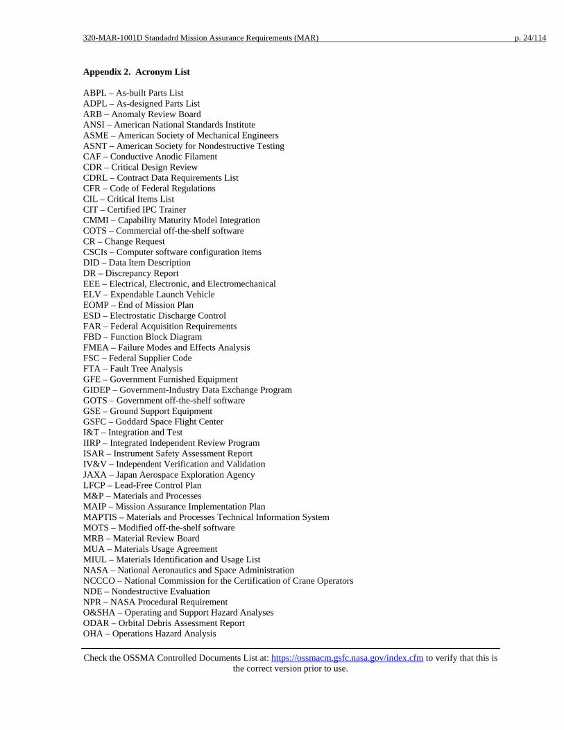
Appendix 2. Acronym List ABPL – As-built Parts List ADPL – As-designed Parts List ARB – Anomaly Review Board ANSI – American National Standards Institute ASME – American Society of Mechanical Engineers ASNT – American Society for Nondestructive Testing CAF – Conductive Anodic Filament CDR – Critical Design Review CDRL – Contract Data Requirements List CFR – Code of Federal Regulations CIL – Critical Items List CIT – Certified IPC Trainer CMMI – Capability Maturity Model Integration COTS – Commercial off-the-shelf software CR – Change Request CSCIs – Computer software configuration items DID – Data Item Description DR – Discrepancy Report EEE – Electrical, Electronic, and Electromechanical ELV – Expendable Launch Vehicle EOMP – End of Mission Plan ESD – Electrostatic Discharge Control FAR – Federal Acquisition Requirements FBD – Function Block Diagram FMEA – Failure Modes and Effects Analysis FSC – Federal Supplier Code FTA – Fault Tree Analysis GFE – Government Furnished Equipment GIDEP – Government-Industry Data Exchange Program GOTS – Government off-the-shelf software GSE – Ground Support Equipment GSFC – Goddard Space Flight Center I&T – Integration and Test IIRP – Integrated Independent Review Program ISAR – Instrument Safety Assessment Report IV&V – Independent Verification and Validation JAXA – Japan Aerospace Exploration Agency LFCP – Lead-Free Control Plan M&P – Materials and Processes MAIP – Mission Assurance Implementation Plan MAPTIS – Materials and Processes Technical Information System MOTS – Modified off-the-shelf software MRB – Material Review Board MUA – Materials Usage Agreement MIUL – Materials Identification and Usage List NASA – National Aeronautics and Space Administration NCCCO – National Commission for the Certification of Crane Operators NDE – Nondestructive Evaluation NPR – NASA Procedural Requirement O&SHA – Operating and Support Hazard Analyses ODAR – Orbital Debris Assessment Report OHA – Operations Hazard Analysis

320-MAR-1001D Standadrd Mission Assurance Requirements (MAR) p. 25/114
Check the OSSMA Controlled Documents List at: https://ossmacm.gsfc.nasa.gov/index.cfm to verify that this is
the correct version prior to use.
PAPL – Project Approved Parts List PCB – Parts control board PCP – Parts Control Plan PDR – Preliminary Design Review PHA – Preliminary Hazard Analyses PIL – Parts Identification List PPQA – Process and Product Quality Assurance PRA – Probabilistic Risk Assessment PSR – Pre-Ship Review PWB – Printed Wiring Board RPP – Reliability Program Plan SAE – Society of Automotive Engineers SCM – Software Configuration Management SDP – Safety Data Package – STS missions only SMA – Safety and Mission Assurance SMA-D – Safety and Mission Assurance Directorate SOW – Statement of Work SQAP – Software Quality Assurance Plan SRP – Systems Review Program SSPP – System Safety Program Plan V&V – Verification and Validation VDD – Version Description Documents VTL – Verification Tracking Log WCA – Worst Case Analysis WFF – Wallops Flight Facility

320-MAR-1001D Standadrd Mission Assurance Requirements (MAR) p. 26/114
Check the OSSMA Controlled Documents List at: https://ossmacm.gsfc.nasa.gov/index.cfm to verify that this is
the correct version prior to use.
Appendix 3. Data Item Descriptions
DID 1-1 MISSION ASSURANCE IMPLEMENTATION PLAN
Title: Mission Assurance Implementation Plan DID No.: 1-1 MAR Paragraph: 1.1 Use:
Documents the developer’s plan for implementing a system safety and mission assurance program.
Reference Documents: Place/Time/Purpose of Delivery:
- Delivered to the Project Office sixty (60) days after contract award for approval
Preparation Information:
The MAIP shall cover: - All flight hardware and software that is designed, built, or provided by the developer and its
subcontractors, or furnished by the government, from project initiation through launch and mission operations
- The ground system that interfaces with flight equipment to the extent necessary to assure the integrity and safety of flight items
- The ground data system
The MAIP shall include a traceability matrix for the mission assurance requirements
320-MAR-1001D Standadrd Mission Assurance Requirements (MAR) p. 27/114
Check the OSSMA Controlled Documents List at: https://ossmacm.gsfc.nasa.gov/index.cfm to verify that this is
the correct version prior to use.
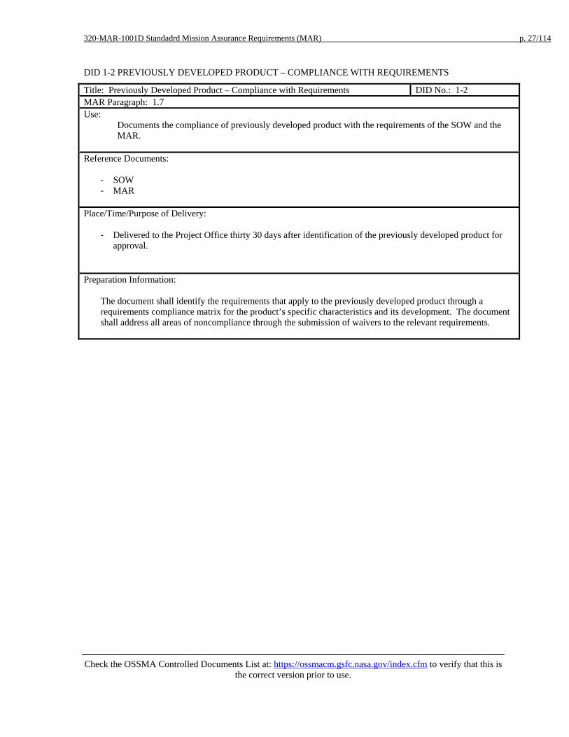
DID 1-2 PREVIOUSLY DEVELOPED PRODUCT – COMPLIANCE WITH REQUIREMENTS
Title: Previously Developed Product – Compliance with Requirements DID No.: 1-2 MAR Paragraph: 1.7 Use:
Documents the compliance of previously developed product with the requirements of the SOW and the MAR.
Reference Documents:
- SOW - MAR
Place/Time/Purpose of Delivery:
- Delivered to the Project Office thirty 30 days after identification of the previously developed product for approval.
Preparation Information:
The document shall identify the requirements that apply to the previously developed product through a requirements compliance matrix for the product’s specific characteristics and its development. The document shall address all areas of noncompliance through the submission of waivers to the relevant requirements.

320-MAR-1001D Standadrd Mission Assurance Requirements (MAR) p. 28/114
Check the OSSMA Controlled Documents List at: https://ossmacm.gsfc.nasa.gov/index.cfm to verify that this is
the correct version prior to use.
DID 2-1 QUALITY MANUAL
Title: Quality Manual DID No.: 2-1 MAR Paragraph: 2.1 Use:
Documents the developer's quality management system.
Reference Documents:
- SAE AS9100 Quality Systems - Aerospace - Model for Quality Assurance in Design, Development, Production, Installation and Servicing
- ISO 10013 Quality Manual Development Guide
Place/Time/Purpose of Delivery:
- Provide with proposal for GSFC review. - After contract award provide updates to the project office within 30 days for review.
Preparation Information:
Prepare a Quality Manual addressing applicable requirements of AS9100; refer to ISO 10013 Quality Manual Development Guide for guidelines on preparation of a quality manual.
320-MAR-1001D Standadrd Mission Assurance Requirements (MAR) p. 29/114
Check the OSSMA Controlled Documents List at: https://ossmacm.gsfc.nasa.gov/index.cfm to verify that this is
the correct version prior to use.
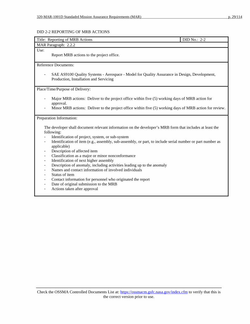
DID 2-2 REPORTING OF MRB ACTIONS
Title: Reporting of MRB Actions DID No.: 2-2 MAR Paragraph: 2.2.2 Use:
Report MRB actions to the project office. Reference Documents:
- SAE AS9100 Quality Systems - Aerospace - Model for Quality Assurance in Design, Development, Production, Installation and Servicing
Place/Time/Purpose of Delivery:
- Major MRB actions: Deliver to the project office within five (5) working days of MRB action for approval.
- Minor MRB actions: Deliver to the project office within five (5) working days of MRB action for review.
Preparation Information:
The developer shall document relevant information on the developer’s MRB form that includes at least the following: - Identification of project, system, or sub-system - Identification of item (e.g., assembly, sub-assembly, or part, to include serial number or part number as
applicable) - Description of affected item - Classification as a major or minor nonconformance - Identification of next higher assembly - Description of anomaly, including activities leading up to the anomaly - Names and contact information of involved individuals - Status of item - Contact information for personnel who originated the report - Date of original submission to the MRB - Actions taken after approval
320-MAR-1001D Standadrd Mission Assurance Requirements (MAR) p. 30/114
Check the OSSMA Controlled Documents List at: https://ossmacm.gsfc.nasa.gov/index.cfm to verify that this is
the correct version prior to use.
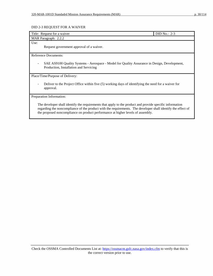
DID 2-3 REQUEST FOR A WAIVER
Title: Request for a waiver DID No.: 2-3 MAR Paragraph: 2.2.2 Use:
Request government approval of a waiver. Reference Documents:
- SAE AS9100 Quality Systems - Aerospace - Model for Quality Assurance in Design, Development, Production, Installation and Servicing
Place/Time/Purpose of Delivery:
- Deliver to the Project Office within five (5) working days of identifying the need for a waiver for approval.
Preparation Information:
The developer shall identify the requirements that apply to the product and provide specific information regarding the noncompliance of the product with the requirements. The developer shall identify the effect of the proposed noncompliance on product performance at higher levels of assembly.

320-MAR-1001D Standadrd Mission Assurance Requirements (MAR) p. 31/114
Check the OSSMA Controlled Documents List at: https://ossmacm.gsfc.nasa.gov/index.cfm to verify that this is
the correct version prior to use.
DID 2-4 MAJOR ANOMALY REPORT
Title: Major Anomaly Report DID No.: 2-4 MAR Paragraph: 2.2.3 Use:
Document anomalies, investigative activities, rationale for closure, and corrective and preventive actions. Reference Documents:
- SAE AS9100 Quality Systems - Aerospace - Model for Quality Assurance in Design, Development, Production, Installation and Servicing
Place/Time/Purpose of Delivery:
- Deliver initial submission to the project office within 24 hours of occurrence for information. - Deliver notice of a change in status within 24 hours of occurrence for information. - Deliver the proposed closure to the project office prior to closure for approval.
Preparation Information:
Document anomalies, changes in status, or proposed closure to identify the following information: - Identification of project, system, or sub-system - Identification of failed item (e.g., assembly, sub-assembly, or part) - Description of item - Identification of next higher assembly - Description of anomaly, including activities leading up to anomaly, if known - Names and contact information of individuals involved in anomaly - Date and time of anomaly - Status of item - Contact information for personnel who originated the report - Date of original submission - Anomaly cause - Corrective actions implemented - Retesting performed and results - Other items affected - Risk ratings – the numerical ratings for failure effect risk and corrective action risk per the following
criteria: a. Failure Effect Risk Rating – indicates the potential impact of the anomaly on hardware or software
performance if it occurred during the mission. Redundancy shall be ignored in establishing this rating. The project shall assign a failure effect risk rating per the following criteria: and corresponding numerical values: 1. Negligible or no effect on mission, system or instrument performance, reliability or safety. 2. Moderate or significant effect on the mission, system or instrument performance, reliability or
safety, defined as: an appreciable change in functional capability, an appreciable degradation of engineering or science telemetry, causing significant operational difficulties or constraints, or causing a reduction in mission lifetime.
3. Catastrophic or major degradation to mission, system or instrument performance, reliability or safety.
b. Corrective Action Rating – indicates the confidence in the root cause and the corrective action. The project shall assign a failure corrective action risk rating per the following criteria: 1. Recurrence very unlikely – the root cause of the anomaly has been determined with confidence
by analysis or test. Corrective action has been determined, implemented, and verified with
320-MAR-1001D Standadrd Mission Assurance Requirements (MAR) p. 32/114
Check the OSSMA Controlled Documents List at: https://ossmacm.gsfc.nasa.gov/index.cfm to verify that this is
the correct version prior to use.
certainty. There is a very low probability of recurrence. 2. Recurrence unlikely – the root cause of the anomaly has not been determined with confidence.
However, some corrective action has been determined, implemented, and verified to the extent that there is a very low probability of recurrence.
3. Recurrence possible – the root cause is considered known and understood with confidence. Corrective action has not been determined, implemented, or verified with certainty. There exists a possibility that the anomaly may recur.
4. Recurrence credible – the root cause has not been determined with confidence. Corrective action has not been determined, implemented, or verified with certainty. There exists a possibility that the anomaly may recur.

320-MAR-1001D Standadrd Mission Assurance Requirements (MAR) p. 33/114
Check the OSSMA Controlled Documents List at: https://ossmacm.gsfc.nasa.gov/index.cfm to verify that this is
the correct version prior to use.
DID 3-1 SYSTEM SAFETY PROGRAM PLAN
Title: System Safety Program Plan DID No.: 3-1 MAR Paragraph: 3.3.1 Use:
The System Safety Program Plan (SSPP) describes the tasks and activities of system safety management and engineering required to identify, evaluate, and eliminate or control hazards to the hardware, software, and system design by reducing the associated risk to an acceptable level throughout the system life cycle.
Reference Documents:
- NPR 8715.7 Expendable Launch Vehicle Payload Safety Program - NASA-STD 8719.24 (with Annex), NASA Expendable Launch Vehicle Payload Safety Requirements
Place/Time/Purpose of Delivery:
- Deliver preliminary plan to the Project Office at SRR for approval. - Deliver final plan to the Project Office forty-five (45) days prior to PDR for approval.
Preparation Information:
The developer shall prepare a SSPP that describes the development and implementation of a system safety program that complies with the requirements of NPR 8715.7, the launch service provider, and launch range safety. The developer shall - Define the roles and responsibilities of personnel - Define the required documentation, applicable requirements documents, and completion schedules for
analyses, reviews, and safety packages - Address support for Safety Reviews, Safety Working Group Meetings and TIMs - Provide for early identification and control of hazards to personnel, facilities, support equipment, and the
flight system during product development, including design, fabrication, test, transportation, and ground activities.
- Address compliance with the launch range safety requirements - Include a safety review process that meets the requirements of NASA-STD-8715.7 Expendable Launch
Vehicle Payloads Safety Program - Address compliance with industrial safety requirements imposed by NASA and OSHA design and
operational needs (e.g., NASA-STD-8719.9 Lifting Devices and Equipment as applicable) and contractually imposed mission unique obligations

320-MAR-1001D Standadrd Mission Assurance Requirements (MAR) p. 34/114
Check the OSSMA Controlled Documents List at: https://ossmacm.gsfc.nasa.gov/index.cfm to verify that this is
the correct version prior to use.
DID 3-2 SAFETY REQUIREMENTS COMPLIANCE CHECKLIST
Title: Safety Requirements Compliance Checklist DID No.: 3-2 MAR Paragraph: 3.3.2 Use:
The checklist indicates for each requirement whether the proposed design is compliant, non-compliant but meets intent, non-compliant, or if the requirement is not applicable. An indication other than compliant will include rationale. Note: the developer shall submit safety waivers for non-compliant design elements per paragraph 3.2.7 and DID 3-10.
Reference Documents:
- NASA-STD 8719.24 (with Annex), NASA Expendable Launch Vehicle Payload Safety Requirements - Reference MAR Section 3.1.1, Mission Related Safety Requirements Documentation
Place/Time/Purpose of Delivery:
- Deliver Preliminary version to the Project Office forty-five (45) days prior to PDR for approval. - Deliver Final version to the Project Office forty-five (45) days prior to CDR for approval.
Preparation Information:
The developer shall prepare a compliance checklist of all design, test, analysis, and data submittal requirements. The following shall be included: - Criteria and requirement. - System - Indication of compliance, noncompliance, or not applicable - Rationale for indications other than compliant - Resolution - Reference - Copies of Range Safety and NASA approved non-compliances, including waivers and equivalent levels of
safety certifications

320-MAR-1001D Standadrd Mission Assurance Requirements (MAR) p. 35/114
Check the OSSMA Controlled Documents List at: https://ossmacm.gsfc.nasa.gov/index.cfm to verify that this is
the correct version prior to use.
DID 3-3 PRELIMINARY HAZARD ANALYSIS
Title: Preliminary Hazard Analysis DID No.: 3-3 MAR Paragraph: 3.3.3.1 Use:
The Preliminary Hazard Analysis (PHA) is used to obtain an initial risk assessment and identify safety critical areas of a concept or system. It is based on the best available data, including mishap data from similar systems and other lessons learned. The developer shall evaluate hazards associated with the proposed design or function for severity, probability, and operational constraints. The developer shall identify safety provisions and alternatives that are needed to eliminate hazards or reduce their associated risk to an acceptable level.
Reference Documents:
- NASA-STD 8719.24 (with Annex), NASA Expendable Launch Vehicle Payload Safety Requirements - JMR 002, Launch Vehicle Payload Safety Requirements - NPR 8715.7, ELV Payload Safety Program - MIL-STD-882E, Standard Practice for System Safety, Appendix B
Place/Time/Purpose of Delivery: Tailoring note: delete the non-applicable requirement
- Submit the PHA with the Preliminary ISAR (DID 3-7) to the Project Office for approval. - Submit the PHA with the SDP I (DID 3-7) to the Project Office for approval.

320-MAR-1001D Standadrd Mission Assurance Requirements (MAR) p. 36/114
Check the OSSMA Controlled Documents List at: https://ossmacm.gsfc.nasa.gov/index.cfm to verify that this is
the correct version prior to use.
Preparation Information: The PHA shall consider the following for identification and evaluation of hazards as a minimum:
• Hazardous components (e.g., fuels, propellants, lasers, explosives, toxic substances, hazardous construction materials, pressure systems, and other energy sources).
• Safety related interface considerations among various elements of the system (e.g., material
compatibilities, electromagnetic interference, inadvertent activation, fire/explosive initiation and propagation, and hardware and software controls). This shall include consideration of the potential contribution by software (including software developed by other contractors/sources) to subsystem/system mishaps. Safety design criteria to control safety-critical software commands and responses (e.g., inadvertent command, failure to command, untimely command or responses, inappropriate magnitude, or other undesired events) shall be identified and appropriate action taken to incorporate them in the software (and related hardware) specifications.
• Environmental constraints including the operating environments (e.g., drop, shock, vibration, extreme
temperatures, noise, exposure to toxic substances, health hazards, fire, electrostatic discharge, lightning, electromagnetic environmental effects, ionizing and non-ionizing radiation including laser radiation).
• Operating, test, maintenance, built-in-tests, diagnostics, and emergency procedures (e.g., human factors
engineering, human error analysis of operator functions, tasks, and requirements; effect of factors such as equipment layout, lighting requirements, potential exposures to toxic materials, effects of noise or radiation on human performance; explosive ordnance render safe and emergency disposal procedures; life support requirements and their safety implications in manned systems, crash safety, egress, rescue, survival, and salvage). Those test unique hazards which will be a direct result of the test and evaluation of the article or vehicle.
• Facilities, real property installed equipment, support equipment (e.g., provisions for storage, assembly,
checkout, proof testing of hazardous systems/assemblies which may involve toxic, flammable, explosive, corrosive or cryogenic materials/wastes; radiation or noise emitters; electrical power sources) and training (e.g. training and certification pertaining to safety operations and maintenance).
• Safety related equipment, safeguards, and possible alternate approaches (e.g., interlocks; system
redundancy; fail safe design considerations using hardware or software controls; subsystem protection; fire detection and suppression systems; personal protective equipment; heating, ventilation, and air-conditioning; and noise or radiation barriers).
• Malfunctions to the system, subsystems, or software. Each malfunction shall be specified, the causing
and resulting sequence of events determined, the degree of hazard determined, and appropriate specification and/or design changes developed.

320-MAR-1001D Standadrd Mission Assurance Requirements (MAR) p. 37/114
Check the OSSMA Controlled Documents List at: https://ossmacm.gsfc.nasa.gov/index.cfm to verify that this is
the correct version prior to use.
DID 3-4 OPERATIONS HAZARD ANALYSIS AND HAZARD VERIFICATION TRACKING LOG
Title: Operations Hazard Analysis and Hazard Verification Tracking Log DID No.: 3-4 MAR Paragraph: 3.3.3.2 Use:
The Operations Hazard Analysis (OHA) and Hazard Verification Tracking Log (VTL) shall demonstrate that hazards related to the operation of hardware and test equipment during integration and test activities have been addressed with respect to facility safety requirements.
Reference Documents:
- GSFC 500-PG-8715.1.2 AETD Safety Manual (for operations at GSFC) - NASA-STD-8719.9 Standard for Lifting Devices and Equipment
Place/Time/Purpose of Delivery:
- Deliver the OHA and Hazard VTL to the Project Office forty-five (45) days prior to Pre-Environmental Review for approval.
Preparation Information:
The OHA shall include the following information: - Introduction – a summary of the major findings of the analysis and the proposed corrective actions and
definitions of special terms, acronyms, and abbreviations. - System Description – a description of system hardware and configuration, with a list of subsystem
components and schedules for integration and testing - Analysis of Hazards - List of real or potential hazards to personnel, equipment, and property during I&T processing - The following information shall be included for each hazard:
- System Component/Phase – the phase and component with which the analysis is concerned; e.g., system, subsystem, component, operating/maintenance procedure, or environmental condition.
- System Description and Hazard Identification, Indication: - A description of expected results from operating the component/subsystem or performing the
operating/maintenance action - A complete description of the actual or potential hazard resulting from normal actions or
equipment failures; indicate whether the hazard will cause personnel injury and equipment damage.
- A description of crew indications which include means of identifying the hazard to operating or maintenance personnel.
- A description of the safety hazards of software controlling hardware systems where the hardware effects are safety critical.
- Effect on System – the detrimental effects of an uncontrolled hazard on the system - Risk Assessment. - Caution and Warning Notes – a list of warnings, cautions, procedures required in operating and
maintenance manuals, training courses, and test plans - Status/Remarks – the status of actions to implement hazard controls.
- References (e.g., test reports, preliminary operating and maintenance manuals, and other hazard analyses)

320-MAR-1001D Standadrd Mission Assurance Requirements (MAR) p. 38/114
Check the OSSMA Controlled Documents List at: https://ossmacm.gsfc.nasa.gov/index.cfm to verify that this is
the correct version prior to use.
DID 3-5 SAFETY HAZARD ANALYSIS ON CRITICAL LIFT EQUIPMENT
Title: Safety Hazard Analysis for Critical Lift Equipment DID No.: 3-5 MAR Paragraph: 3.3.3.3 Use:
A recognized safety hazard analysis, such as fault tree analysis, FMEA, Operating and Support Hazard Analysis (O&SHA), shall be performed on all lifting devices used for critical lifts.
Reference Documents:
- NASA-STD-8719.9 Standard for Lifting Devices and Equipment, Para. 4.2.3, 5.2.3, 6.2.3, 8.2.3, 9.2.3, 11.2.3, 12.2.3, 13.2.3, and A.4.7
Place/Time/Purpose of Delivery:
- Deliver the analysis to the project office thirty (30) days prior to use in a critical lift for approval. - Deliver a revised analysis to the project office fifteen (15) days prior to use in a critical lift for approval.
Preparation Information:
The analysis shall determine potential sources of danger, identify failure modes, and recommend resolutions and a system of risk acceptance for those conditions found in the hardware-facility-environment-human relationship that could cause loss of life, personal injury, and loss of or damage to the crane, facility, or load.

320-MAR-1001D Standadrd Mission Assurance Requirements (MAR) p. 39/114
Check the OSSMA Controlled Documents List at: https://ossmacm.gsfc.nasa.gov/index.cfm to verify that this is
the correct version prior to use.
DID 3-6 OPERATING AND SUPPORT HAZARD ANALYSIS
Title: Operating and Support Hazard Analysis (O&SHA) DID No.: 3-6 MAR Paragraph: 3.3.3.4 Use:
The Operating & Support Hazard Analysis (O&SHA) addresses hazards to personnel and equipment that are introduced via the usage of operational and support procedures during testing, transportation, storage, and integration operations at the launch site. Its primary purpose is to evaluate the adequacy of procedures used to eliminate, control or mitigate identified hazards in order to ensure implementation of safety requirements for personnel, procedures, and equipment used during testing, transportation, storage, and integration operations at the launch site.
Reference Documents:
- NASA-STD 8719.24 (with Annex), NASA Expendable Launch Vehicle Payload Safety Requirements - NPR 8715.7, ELV Payload Safety Program
Place/Time/Purpose of Delivery:
Tailoring note: delete the non-applicable requirement.
- Deliver the results of the O&SHA to the Project Office as a part of the Intermediate & Final ISARs (DID 3-7) for approval
- Deliver the results of the O&SHA to the Project Office as a part of the SDP II & SDP III (DID 3-7) for approval
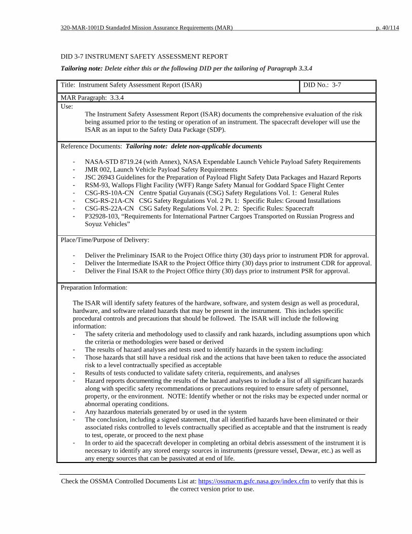
320-MAR-1001D Standadrd Mission Assurance Requirements (MAR) p. 40/114
Check the OSSMA Controlled Documents List at: https://ossmacm.gsfc.nasa.gov/index.cfm to verify that this is
the correct version prior to use.
DID 3-7 INSTRUMENT SAFETY ASSESSMENT REPORT
Tailoring note: Delete either this or the following DID per the tailoring of Paragraph 3.3.4 Title: Instrument Safety Assessment Report (ISAR) DID No.: 3-7
MAR Paragraph: 3.3.4 Use:
The Instrument Safety Assessment Report (ISAR) documents the comprehensive evaluation of the risk being assumed prior to the testing or operation of an instrument. The spacecraft developer will use the ISAR as an input to the Safety Data Package (SDP).
Reference Documents: Tailoring note: delete non-applicable documents
- NASA-STD 8719.24 (with Annex), NASA Expendable Launch Vehicle Payload Safety Requirements - JMR 002, Launch Vehicle Payload Safety Requirements - JSC 26943 Guidelines for the Preparation of Payload Flight Safety Data Packages and Hazard Reports - RSM-93, Wallops Flight Facility (WFF) Range Safety Manual for Goddard Space Flight Center - CSG-RS-10A-CN Centre Spatial Guyanais (CSG) Safety Regulations Vol. 1: General Rules - CSG-RS-21A-CN CSG Safety Regulations Vol. 2 Pt. 1: Specific Rules: Ground Installations - CSG-RS-22A-CN CSG Safety Regulations Vol. 2 Pt. 2: Specific Rules: Spacecraft - P32928-103, “Requirements for International Partner Cargoes Transported on Russian Progress and
Soyuz Vehicles”
Place/Time/Purpose of Delivery:
- Deliver the Preliminary ISAR to the Project Office thirty (30) days prior to instrument PDR for approval. - Deliver the Intermediate ISAR to the Project Office thirty (30) days prior to instrument CDR for approval. - Deliver the Final ISAR to the Project Office thirty (30) days prior to instrument PSR for approval.
Preparation Information:
The ISAR will identify safety features of the hardware, software, and system design as well as procedural, hardware, and software related hazards that may be present in the instrument. This includes specific procedural controls and precautions that should be followed. The ISAR will include the following information: - The safety criteria and methodology used to classify and rank hazards, including assumptions upon which
the criteria or methodologies were based or derived - The results of hazard analyses and tests used to identify hazards in the system including: - Those hazards that still have a residual risk and the actions that have been taken to reduce the associated
risk to a level contractually specified as acceptable - Results of tests conducted to validate safety criteria, requirements, and analyses - Hazard reports documenting the results of the hazard analyses to include a list of all significant hazards
along with specific safety recommendations or precautions required to ensure safety of personnel, property, or the environment. NOTE: Identify whether or not the risks may be expected under normal or abnormal operating conditions.
- Any hazardous materials generated by or used in the system - The conclusion, including a signed statement, that all identified hazards have been eliminated or their
associated risks controlled to levels contractually specified as acceptable and that the instrument is ready to test, operate, or proceed to the next phase
- In order to aid the spacecraft developer in completing an orbital debris assessment of the instrument it is necessary to identify any stored energy sources in instruments (pressure vessel, Dewar, etc.) as well as any energy sources that can be passivated at end of life.
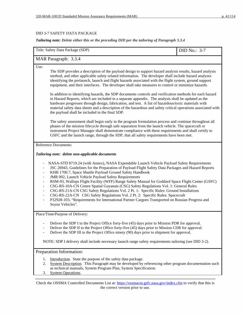
320-MAR-1001D Standadrd Mission Assurance Requirements (MAR) p. 41/114
Check the OSSMA Controlled Documents List at: https://ossmacm.gsfc.nasa.gov/index.cfm to verify that this is
the correct version prior to use.
DID 3-7 SAFETY DATA PACKAGE
Tailoring note: Delete either this or the preceding DID per the tailoring of Paragraph 3.3.4 Title: Safety Data Package (SDP) DID No.: 3-7
MAR Paragraph: 3.3.4 Use:
The SDP provides a description of the payload design to support hazard analysis results, hazard analysis method, and other applicable safety related information. The developer shall include hazard analyses identifying the prelaunch, launch and flight hazards associated with the flight system, ground support equipment, and their interfaces. The developer shall take measures to control or minimize hazards.
In addition to identifying hazards, the SDP documents controls and verification methods for each hazard in Hazard Reports, which are included in a separate appendix. The analysis shall be updated as the hardware progresses through design, fabrication, and test. A list of hazardous/toxic materials with material safety data sheets and a description of the hazardous and safety critical operations associated with the payload shall be included in the final SDP. The safety assessment shall begin early in the program formulation process and continue throughout all phases of the mission lifecycle through safe separation from the launch vehicle. The spacecraft or instrument Project Manager shall demonstrate compliance with these requirements and shall certify to GSFC and the launch range, through the SDP, that all safety requirements have been met.
Reference Documents: Tailoring note: delete non-applicable documents
- NASA-STD 8719.24 (with Annex), NASA Expendable Launch Vehicle Payload Safety Requirements - JSC 26943, Guidelines for the Preparation of Payload Flight Safety Data Packages and Hazard Reports - KHB 1700.7, Space Shuttle Payload Ground Safety Handbook - JMR 002, Launch Vehicle Payload Safety Requirements - RSM-93, Wallops Flight Facility (WFF) Range Safety Manual for Goddard Space Flight Center (GSFC) - CSG-RS-10A-CN Centre Spatial Guyanais (CSG) Safety Regulations Vol. 1: General Rules - CSG-RS-21A-CN CSG Safety Regulations Vol. 2 Pt. 1: Specific Rules: Ground Installations - CSG-RS-22A-CN CSG Safety Regulations Vol. 2 Pt. 2: Specific Rules: Spacecraft - P32928-103, “Requirements for International Partner Cargoes Transported on Russian Progress and
Soyuz Vehicles”. Place/Time/Purpose of Delivery:
- Deliver the SDP I to the Project Office forty-five (45) days prior to Mission PDR for approval. - Deliver the SDP II to the Project Office forty-five (45) days prior to Mission CDR for approval. - Deliver the SDP III to the Project Office ninety (90) days prior to shipment for approval. NOTE: SDP I delivery shall include necessary launch range safety requirements tailoring (see DID 3-2).
Preparation Information: 1. Introduction. State the purpose of the safety data package. 2. System Description. This Paragraph may be developed by referencing other program documentation such
as technical manuals, System Program Plan, System Specification. 3. System Operations.

320-MAR-1001D Standadrd Mission Assurance Requirements (MAR) p. 42/114
Check the OSSMA Controlled Documents List at: https://ossmacm.gsfc.nasa.gov/index.cfm to verify that this is
the correct version prior to use.
a. A description of the procedures for operating, testing, and maintaining the system, including the safety features and controls.
b. A description of special safety procedures needed to assure safe operations, test and maintenance, including emergency procedures.
c. A description of anticipated operating environments and specific operator skills. d. A description of special facility requirements or personal equipment to support the system.
4. Systems Safety Engineering Assessment. This Paragraph shall include: a. A summary of the criteria and methodology for classifying and ranking hazardous conditions. b. A description of the analyses and tests performed to identify inherent hazardous conditions, including
the software safety analysis c. A separate appendix documenting the Hazard Reports by subsystem or major component level with
the Hazard Reports being listed in alphanumeric order based on the chosen Hazard Report numbering scheme.
i. A discussion of the actions taken to eliminate or control these items. ii. A discussion of the effects of these controls on the probability of occurrence and severity
level of potential mishaps. iii. A discussion of the residual risks that remain after the controls are applied or for which no
controls could be applied. iv. A discussion of the results of tests conducted to validate safety criteria requirements and
analyses, including a reference to the specific test/analysis/inspection reports that provide this verification. These reports shall be made available to the Project office upon request.
5. Conclusions and Recommendations. This Paragraph shall include: a. An assessment of the results of the safety program efforts; a list of significant hazards and specific
safety recommendations to ensure the safety of personnel and property. b. For hazardous materials:
(1) Material identification as to type, quantity, and hazards. (2) Safety precautions and procedures for use, storage, transportation, and disposal. (3) A copy of the Material Safety Data Sheet (OSHA Form 20 or DD Form 1813).
c. Appropriate radiation forms/analysis. d. Reference material to include a list of all pertinent references such as Test Reports, Preliminary
Operating Manuals and Maintenance Manuals e. Recommendations applicable to the safe interface of this system with the other system(s). f. A statement signed by the developer’s System Safety Manager and Program Manager certifying that
all identified hazards have been eliminated or controlled and that the system is ready to test, operate, or proceed to the next acquisition phase.

320-MAR-1001D Standadrd Mission Assurance Requirements (MAR) p. 43/114
Check the OSSMA Controlled Documents List at: https://ossmacm.gsfc.nasa.gov/index.cfm to verify that this is
the correct version prior to use.
DID 3-8 VERIFICATION TRACKING LOG
Title: Verification Tracking Log DID No.: 3-8 MAR Paragraph: 3.3.5 Use:
Provides documentation of a Hazard Control and Verification Tracking process as a closed-loop system to ensure that safety compliance has been satisfied in accordance to applicable launch range safety requirements.
Reference Documents: Tailoring note: delete non-applicable documents
- NASA-STD 8719.24 (with Annex), NASA Expendable Launch Vehicle Payload Safety Requirements - KHB 1700.7, Space Shuttle Payload Ground Safety Handbook - RSM-93, WFF Range Safety Manual for Goddard Space Flight Center (GSFC) - CSG-RS-10A-CN Centre Spatial Guyanais (CSG) Safety Regulations Vol. 1: General Rules - CSG-RS-21A-CN CSG Safety Regulations Vol. 2 Pt. 1: Specific Rules: Ground Installations - CSG-RS-22A-CN CSG Safety Regulations Vol. 2 Pt. 2: Specific Rules: Spacecraft
Place/Time/Purpose of Delivery: Tailoring note: delete non-applicable requirements:
- The Verification Tracking Log (VTL) that identifies hazard controls that are not verified as closed shall be delivered to the Project Office with the final ISAR (DID 3-7) for review.
- The Verification Tracking Log (VTL) that identifies hazard controls that are not verified as closed shall be delivered to the Project Office with the SDP III DID (3-7) for review.
- Regular updates to this log shall be provided to the Project Office for review until all hazard controls are verified as closed.
Note: the developer shall close items with the appropriate verification rationale (e.g., test reports, analysis reports, procedure step references, etc.) prior to first operational use or restraint.
Preparation Information:
The VTL provides documentation that demonstrates the process of verifying the control of all hazards by test, analysis, inspection, similarity to previously qualified hardware, or any combination of these activities. All verifications that are listed on the hazard reports shall reference the specific test/analysis/inspection reports with a summary of the pertinent results. Results of these tests/analyses/inspections shall be available for review and submitted in accordance with the contract schedule and applicable launch site range safety requirements. The VTL shall contain the following information in tabular format: - Hazard Report number - Safety Verification number - Description (Identify procedures/analyses by number and title) - Constraints on Launch Site Operations - Independent Verification Required (e.g., mandatory inspection points) - Scheduled Completion Date - Completion Date - Method of Closure
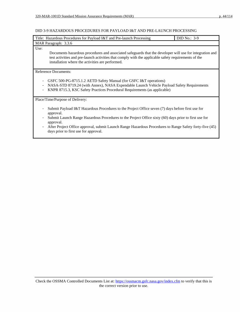
320-MAR-1001D Standard Mission Assurance Requirements (MAR) p. 44/114
Check the OSSMA Controlled Documents List at: https://ossmacm.gsfc.nasa.gov/index.cfm to verify that this is
the correct version prior to use.
DID 3-9 HAZARDOUS PROCEDURES FOR PAYLOAD I&T AND PRE-LAUNCH PROCESSING
Title: Hazardous Procedures for Payload I&T and Pre-launch Processing DID No.: 3-9 MAR Paragraph: 3.3.6 Use:
Documents hazardous procedures and associated safeguards that the developer will use for integration and test activities and pre-launch activities that comply with the applicable safety requirements of the installation where the activities are performed.
Reference Documents:
- GSFC 500-PG-8715.1.2 AETD Safety Manual (for GSFC I&T operations) - NASA-STD 8719.24 (with Annex), NASA Expendable Launch Vehicle Payload Safety Requirements - KNPR 8715.3, KSC Safety Practices Procedural Requirements (as applicable)
Place/Time/Purpose of Delivery:
- Submit Payload I&T Hazardous Procedures to the Project Office seven (7) days before first use for approval.
- Submit Launch Range Hazardous Procedures to the Project Office sixty (60) days prior to first use for approval.
- After Project Office approval, submit Launch Range Hazardous Procedures to Range Safety forty-five (45) days prior to first use for approval.
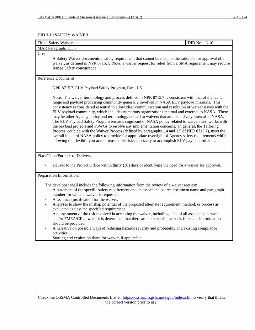
320-MAR-1001D Standard Mission Assurance Requirements (MAR) p. 45/114
Check the OSSMA Controlled Documents List at: https://ossmacm.gsfc.nasa.gov/index.cfm to verify that this is
the correct version prior to use.
DID 3-10 SAFETY WAIVER
Title: Safety Waiver DID No.: 3-10 MAR Paragraph: 3.3.7 Use:
A Safety Waiver documents a safety requirement that cannot be met and the rationale for approval of a waiver, as defined in NPR 8715.7. Note: a waiver request for relief from a SMA requirement may require Range Safety concurrence.
Reference Documents:
- NPR 8715.7, ELV Payload Safety Program, Para. 1.5 Note: The waiver terminology and process defined in NPR 8715.7 is consistent with that of the launch range and payload processing community generally involved in NASA ELV payload missions. This consistency is considered essential to allow clear communication and resolution of waiver issues with the ELV payload community, which includes numerous organizations internal and external to NASA. There may be other Agency policy and terminology related to waivers that are exclusively internal to NASA. The ELV Payload Safety Program remains cognizant of NASA policy related to waivers and works with the payload projects and PSWGs to resolve any implementation concerns. In general, the Tailoring Process, coupled with the Waiver Process (defined by paragraphs 1.4 and 1.5 of NPR 8715.7), meet the overall intent of NASA policy to provide for appropriate oversight of Agency safety requirements while allowing the flexibility to accept reasonable risks necessary to accomplish ELV payload missions.
Place/Time/Purpose of Delivery:
- Deliver to the Project Office within thirty (30) days of identifying the need for a waiver for approval.
Preparation Information:
The developer shall include the following information from the review of a waiver request: - A statement of the specific safety requirement and its associated source document name and paragraph
number for which a waiver is requested. - A technical justification for the waiver. - Analyses to show the mishap potential of the proposed alternate requirement, method, or process as
evaluated against the specified requirement. - An assessment of the risk involved in accepting the waiver, including a list of all associated hazards
and/or FMEA/CILs; when it is determined that there are no hazards, the basis for such determination should be provided.
- A narrative on possible ways of reducing hazards severity and probability and existing compliance activities.
- Starting and expiration dates for waiver, if applicable.

320-MAR-1001D Standard Mission Assurance Requirements (MAR) p. 46/114
Check the OSSMA Controlled Documents List at: https://ossmacm.gsfc.nasa.gov/index.cfm to verify that this is
the correct version prior to use.
DID 3-11 INPUT TO ORBITAL DEBRIS ASSESSMENT REPORT (ODAR) AND END OF MISSION PLAN (EOMP) Title: Input to Orbital Debris Assessment Report (ODAR) and End of Mission Plan (EOMP)
DID No.: 3-11
MAR Paragraph: 3.3.8 Use:
Ensure NASA requirements for post mission orbital debris control and end of mission planning are met.
Reference Documents:
- NASA-STD-8719.14 Process for Limiting Orbital Debris (Appendix A for ODAR, & Appendix B for EOMP
Place/Time/Purpose of Delivery:
- Deliver preliminary inputs to the Project Office fifteen (15) days prior to mission PDR for information. - Deliver interim inputs to the Project Office sixty (60) days prior to mission CDR for information. - Deliver the final/updated inputs to the Project Office 90 days prior to PSR for information.
Preparation Information:
NASA-STD-8719.14 Process for Limiting Orbital Debris Appendix A (ODAR) and Appendix B (EOMP) provide details on what information is required for the Project Office to complete these analyses NOTE: Orbital Debris Assessment Software is available for download from Johnson Space Center at URL: http://sn-callisto.jsc.nasa.gov/mitigate/das/das.html
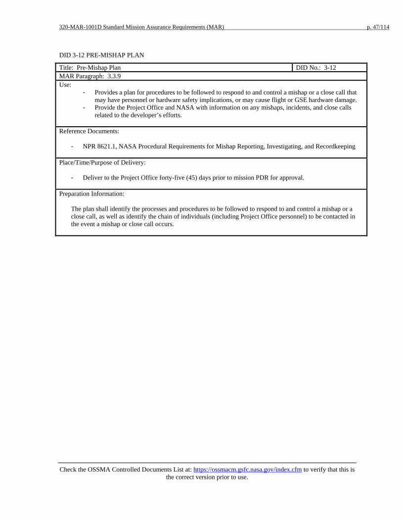
320-MAR-1001D Standard Mission Assurance Requirements (MAR) p. 47/114
Check the OSSMA Controlled Documents List at: https://ossmacm.gsfc.nasa.gov/index.cfm to verify that this is
the correct version prior to use.
DID 3-12 PRE-MISHAP PLAN
Title: Pre-Mishap Plan DID No.: 3-12 MAR Paragraph: 3.3.9 Use:
- Provides a plan for procedures to be followed to respond to and control a mishap or a close call that may have personnel or hardware safety implications, or may cause flight or GSE hardware damage.
- Provide the Project Office and NASA with information on any mishaps, incidents, and close calls related to the developer’s efforts.
Reference Documents:
- NPR 8621.1, NASA Procedural Requirements for Mishap Reporting, Investigating, and Recordkeeping
Place/Time/Purpose of Delivery:
- Deliver to the Project Office forty-five (45) days prior to mission PDR for approval.
Preparation Information:
The plan shall identify the processes and procedures to be followed to respond to and control a mishap or a close call, as well as identify the chain of individuals (including Project Office personnel) to be contacted in the event a mishap or close call occurs.

320-MAR-1001D Standard Mission Assurance Requirements (MAR) p. 48/114
Check the OSSMA Controlled Documents List at: https://ossmacm.gsfc.nasa.gov/index.cfm to verify that this is
the correct version prior to use.
DID 3-13 RANGE SAFETY FORMS
Title: Range Safety Forms DID No.: 3-13 MAR Paragraph: 3.3.10 Use:
Submitted to Launch Range Safety for assessment of range safety.
Reference Documents:
- KTI-5212 Material Selection List for Plastic Films, Foams, and Adhesive Tapes - KNPR 1860.1 KSC Ionizing Radiation Protection Program - KNPR 1860.2 KSC Non-Ionizing Radiation Protection Program
Place/Time/Purpose of Delivery: Tailoring note: delete the non-applicable requirement:
- Deliver to the Project Office with the Final ISAR (DID 3-7) for review. - Deliver to the Project Office with the SDP III (DID 3-7) for review.
Preparation Information:
The developer shall complete the following forms: - KTI-5212 Material Selection List for Plastic Films, Foams, and Adhesive Tapes - KSC FORM 16-294 NS Radiation Training and Experience Summary (Ionizing Radiation) - KSC FORM 16-295 NS Radiation Use Request/Authorization (Radiation Materials) - KSC FORM 16-447 Laser Device Use Request/Authorization - KSC FORM 16-450 NS Radiation Training & Experience Summary (Non-ionizing Radiation) - KSC FORM 16-451 NS Radio Frequency/Microwave System Use Request/ Authorization - KSC Form 26-551V2 Process Waste Questionnaire - AF Form 813 Request for Environmental Impact Analysis NOTE: - Material Selection Forms are available for download from ELV Payload Safety Program website at URL:
http://kscsma.ksc.nasa.gov/ELVPayloadSafety/Requirements.html - Radiation Forms are available for download from ELV Payload Safety Program website at URL:
http://kscsma.ksc.nasa.gov/ELVPayloadSafety/Forms.html
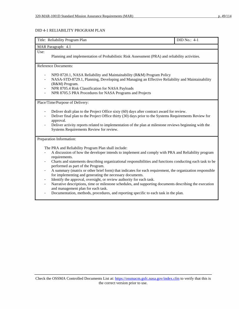
320-MAR-1001D Standard Mission Assurance Requirements (MAR) p. 49/114
Check the OSSMA Controlled Documents List at: https://ossmacm.gsfc.nasa.gov/index.cfm to verify that this is
the correct version prior to use.
DID 4-1 RELIABILITY PROGRAM PLAN
Title: Reliability Program Plan DID No.: 4-1
MAR Paragraph: 4.1 Use:
Planning and implementation of Probabilistic Risk Assessment (PRA) and reliability activities. Reference Documents:
- NPD 8720.1, NASA Reliability and Maintainability (R&M) Program Policy - NASA-STD-8729.1, Planning, Developing and Managing an Effective Reliability and Maintainability
(R&M) Program. - NPR 8705.4 Risk Classification for NASA Payloads - NPR 8705.5 PRA Procedures for NASA Programs and Projects
Place/Time/Purpose of Delivery:
- Deliver draft plan to the Project Office sixty (60) days after contract award for review. - Deliver final plan to the Project Office thirty (30) days prior to the Systems Requirements Review for
approval. - Deliver activity reports related to implementation of the plan at milestone reviews beginning with the
Systems Requirements Review for review.
Preparation Information:
The PRA and Reliability Program Plan shall include: - A discussion of how the developer intends to implement and comply with PRA and Reliability program
requirements. - Charts and statements describing organizational responsibilities and functions conducting each task to be
performed as part of the Program. - A summary (matrix or other brief form) that indicates for each requirement, the organization responsible
for implementing and generating the necessary documents. - Identify the approval, oversight, or review authority for each task. - Narrative descriptions, time or milestone schedules, and supporting documents describing the execution
and management plan for each task. - Documentation, methods, procedures, and reporting specific to each task in the plan.

320-MAR-1001D Standard Mission Assurance Requirements (MAR) p. 50/114
Check the OSSMA Controlled Documents List at: https://ossmacm.gsfc.nasa.gov/index.cfm to verify that this is
the correct version prior to use.
DID 4-2: PROBABILISTIC RISK ASSESSMENT
Note: Delete this DID and paragraph 4.2 if a PRA is not required. Use this DID and the appropriate paragraph of 4.2 if the developer is performing the PRA and delete the following DID 4-2.
Title: Probabilistic Risk Assessment DID No.: 4-2
MAR Paragraph: 4.2
Use:
To provide a structured and disciplined approach to: analyzing system risk; supporting management decisions; improving safety, operations, performing maintenance and upgrades; improving performance; reducing costs.
Reference Documents:
- NPR 8705.4 Risk Classification for NASA Payloads - NPR 8705.5 Technical Probabilistic Risk Assessment (PRA) Procedures for Safety and Mission Success
for NASA Programs and Projects - NPR 8715.3 NASA General Safety Program Requirements - PRA Procedures Guide for NASA Managers and Practitioners
(http://www.hq.nasa.gov/office/codeq/doctree/praguide.pdf) Place/Time/Purpose of Delivery:
- Deliver a PRA plan to the Project office sixty (60) days after contract award for review (Note: PRA may be stand-alone document or included as part of the Reliability Program Plan (RPP), Risk Management Plan (RMP), etc. The PRA Plan shall meet requirements delineated in DID 4-1.).
- Deliver interim PRA to the Project Office thirty (30) days prior to PDR for review. - Deliver updated interim PRA to the Project Office thirty (30) days prior to CDR for review. - Deliver updated interim PRA to the Project Office thirty (30) days prior to MOR for review. - Deliver final PRA to the Project Office thirty (30) days prior to FOR for approval.
Preparation Information:
The PRA shall be performed in accordance with NPR 8705.5 and include the following: - The objective and scope of the PRA - End-states-of-interest to the decision-maker, - Definition of the mission phases and success criteria, - Initiating event categories, - Top level scenarios, - Initiating and pivotal event models (e.g., fault trees and phenomenological event models), including
assessments of common cause failure modes - Data development for probability calculations, - Integrated model and quantification to obtain risk estimates, - Assessment of uncertainties, - Summary of results and conclusions, including a ranking of the lead contributors to risk.

320-MAR-1001D Standard Mission Assurance Requirements (MAR) p. 51/114
Check the OSSMA Controlled Documents List at: https://ossmacm.gsfc.nasa.gov/index.cfm to verify that this is
the correct version prior to use.
DID 4-2: INPUT FOR THE PROBALISTIC RISK ASSESSMENT (PRA)
Note:. Delete this DID and paragraph 4.2 if a PRA is not required. Delete the previous DID 4-2 and use this DID if a PRA required and is being performed by GSFC. Title: Information for the Probabilistic Risk Assessment (PRA) DID No.: 4-2 MAR Paragraph: 4-2 Use:
To provide a structured and disciplined approach to: analyzing system risk; supporting management decisions; address safety, operations, maintenance, and upgrades; manage performance; manage costs.
Reference: - NPR 8705.4 Risk Classification for NASA Payloads - NPR 8705.5 Technical Probabilistic Risk Assessment (PRA) Procedures for Safety and Mission Success for
NASA Programs and Projects - NPR 8715.3 NASA General Safety Program Requirements - PRA Procedures Guide for NASA Managers and Practitioners
(http://www.hq.nasa.gov/office/codeq/doctree/praguide.pdf) Related Documents
None Place/Time/Purpose of Delivery:
- Deliver preliminary heritage information, including the percent applicable, to the Project Office sixty (60) days after contract award for information.
- Deliver updated heritage information, including the percent applicable heritage to the subject mission, to the Project Office thirty (30) days to prior major milestone reviews beginning with the SRR for information.
- Deliver product information and process information for elements within the scope of the Mission PRA to the Project Office thirty (90) days prior to the PDR and thirty (30) days prior to subsequent major milestone reviews for information.
Preparation Information:
The government will provide a notification to the developer of the scope and/or area of inputs needed to support the risk assessment 30 days prior to needing information in preparation of the PRA. Types of information needed may include heritage information (e.g., current flight history, current operating hours, operational and storage environments, TRLs, etc.), product information (e.g., hardware and/or software configurations, parts lists, schematics), interim analysis (e.g, working-level copies of fault tree analysis, failure modes and effects analysis, reliability predictions, etc) and/or process information (e.g., design documents, manufacturing documents, parts program documents,etc) germane to the element(s) being evaluated within the scope of Mission PRA and Instrument development. The developer and their collaborators will provide access to the information necessary to support the scope of the Mission PRA.

320-MAR-1001D Standard Mission Assurance Requirements (MAR) p. 52/114
Check the OSSMA Controlled Documents List at: https://ossmacm.gsfc.nasa.gov/index.cfm to verify that this is
the correct version prior to use.
DID 4-3: FAILURE MODE AND EFFECTS ANALYSIS AND CRITICAL ITEMS LIST
Title: Failure Mode and Effects Analysis (FMEA) and Critical Items List (CIL) DID No.: 4-3
MAR Paragraph: 4.3
Use: Used to evaluate design against requirements, to identify single point failures and hazards, and to identify modes of failure within a system design for the early mitigation of potential catastrophic and critical failures.
Reference Documents
- GSFC Flight Assurance Procedure, FAP P-322-208, Performing a Failure Mode and Effects Analysis - NPR 8705.4 Risk Classification for NASA Payloads
Place/Time/Purpose of Delivery:
- Deliver preliminary FMEA to the Project Office thirty (30) days before PDR for review. - Deliver final FMEA to the Project Office thirty (30) days prior to CDR for approval. - Deliver updated FMEA and CIL to the Project Office thirty (30) days prior to each subsequent milestone
review leading up to Launch for approval.
Preparation Information:
The FMEA Report shall include the following: - A discussion of the approach of the analysis, methodologies, assumptions, results, conclusions, and
recommendations. - Objectives - Level of the analysis - Ground rules - Functional description - Functional block diagrams - Reliability block diagrams - Equipment analyzed - Data sources used - Problems identified - Single-point failure analysis, to include the root cause, mitigation, and retention rationale for those with
severity categories 1, 1R, 1S,2 or 2R. - Corrective actions - Work sheets identifying failure modes, causes, severity category, and effects at the item, next higher
level, and mission level, detection methods, and mitigating provisions. - Critical Items List (CIL) for severity categories 1, 1R, 1S, 2, and 2R, including item identification, cross-
reference to FMEA line items, and retention rationale. Appropriate retention rationale may include design features, historical performance, acceptance testing, manufacturing product assurance, elimination of undesirable failure modes, and failure detection methods.
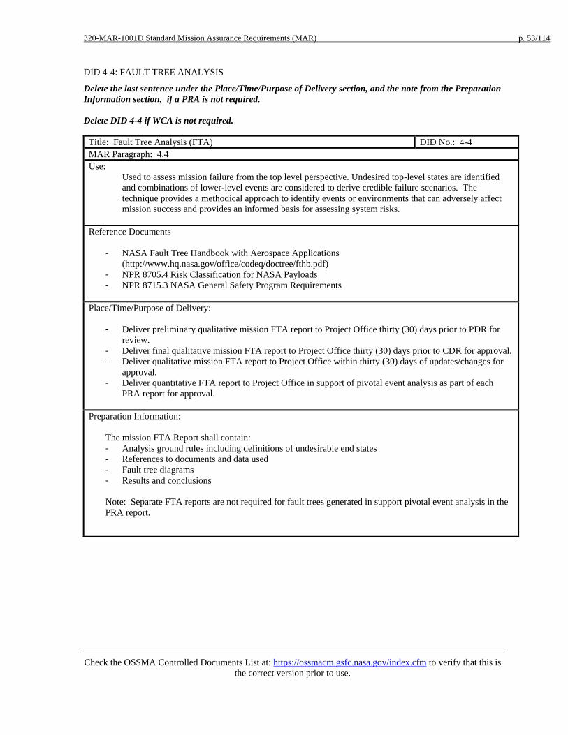
320-MAR-1001D Standard Mission Assurance Requirements (MAR) p. 53/114
Check the OSSMA Controlled Documents List at: https://ossmacm.gsfc.nasa.gov/index.cfm to verify that this is
the correct version prior to use.
DID 4-4: FAULT TREE ANALYSIS
Delete the last sentence under the Place/Time/Purpose of Delivery section, and the note from the Preparation Information section, if a PRA is not required. Delete DID 4-4 if WCA is not required.
Title: Fault Tree Analysis (FTA) DID No.: 4-4 MAR Paragraph: 4.4 Use:
Used to assess mission failure from the top level perspective. Undesired top-level states are identified and combinations of lower-level events are considered to derive credible failure scenarios. The technique provides a methodical approach to identify events or environments that can adversely affect mission success and provides an informed basis for assessing system risks.
Reference Documents
- NASA Fault Tree Handbook with Aerospace Applications (http://www.hq.nasa.gov/office/codeq/doctree/fthb.pdf)
- NPR 8705.4 Risk Classification for NASA Payloads - NPR 8715.3 NASA General Safety Program Requirements
Place/Time/Purpose of Delivery:
- Deliver preliminary qualitative mission FTA report to Project Office thirty (30) days prior to PDR for review.
- Deliver final qualitative mission FTA report to Project Office thirty (30) days prior to CDR for approval. - Deliver qualitative mission FTA report to Project Office within thirty (30) days of updates/changes for
approval. - Deliver quantitative FTA report to Project Office in support of pivotal event analysis as part of each
PRA report for approval. Preparation Information:
The mission FTA Report shall contain: - Analysis ground rules including definitions of undesirable end states - References to documents and data used - Fault tree diagrams - Results and conclusions
Note: Separate FTA reports are not required for fault trees generated in support pivotal event analysis in the PRA report.

320-MAR-1001D Standard Mission Assurance Requirements (MAR) p. 54/114
Check the OSSMA Controlled Documents List at: https://ossmacm.gsfc.nasa.gov/index.cfm to verify that this is
the correct version prior to use.
DID 4-5: PARTS STRESS ANALYSIS
Delete DID 4-5 if Reliability Assessments and Predictions is not required.
Title: Parts Stress Analysis DID No.: 4-5 MAR Paragraph: 4.5 Use:
Provides EEE parts stress analyses for verifying circuit design conformance to derating requirements; demonstrates that environmental operational stresses on parts comply with project derating requirements.
Reference Documents
- GSFC EEE-INST-002 <http://nepp.nasa.gov/DocUploads/FFB52B88-36AE-4378-A05B2C084B5EE2CC/EEE-INST-002_add1.pdf>
- NASA Parts Selection List <http://nepp.nasa.gov/npsl/index.htm>
Place/Time/Purpose of Delivery:
- Deliver Parts Stress Analysis Report to Project Office forty-five (45) days prior to CDR for review. - Deliver revisions to Project Office within thirty (30) days of changes for review.
Preparation Information:
The Parts Stress Analysis Report shall contain: - Analysis ground rules - Reference documents and data used - Results and conclusions including:
o Design trade study results o Parts stress analysis results impacting design or risk decisions
- Analysis worksheets; the worksheets at a minimum shall include: o Part identification (traceable to circuit diagrams) o Assumed environmental (consider all expected environments) o Rated stress o Applied stress (consider all significant operating parameter stresses at the extremes of
anticipated environments) o Ratio of applied-to-rated stress

320-MAR-1001D Standard Mission Assurance Requirements (MAR) p. 55/114
Check the OSSMA Controlled Documents List at: https://ossmacm.gsfc.nasa.gov/index.cfm to verify that this is
the correct version prior to use.
DID 4-6: WORST CASE ANALYSIS
Title: Worst Case Analysis DID No.: 4-6 MAR Paragraph: 4.6 Use:
Demonstrate design margins in electronic and electrical circuits, optics, and electromechanical and mechanical items.
Reference Documents
- NPD 8720.1, NASA Reliability and Maintainability (R&M) Program Policy. - NASA-STD-8729.1, Planning, Developing and Managing an Effective R&M Program. - NPR 8705.4, Risk Classification for NASA Payloads
Place/Time/Purpose of Delivery:
- Deliver Worst Case Analysis Report to Project Office thirty (30) days prior to CDR for review. - Deliver revisions to Worst Case Analysis Report to Project Office within thirty (30) days for review.
Preparation Information:
The Worst Case Analysis Report shall include the following: - Address worst case conditions performed on each component. - Discuss how each analysis includes the mission life. - Discuss consideration of critical parameters at maximum and minimum limits. - The effect of environmental stresses on the operational parameters being evaluated.

320-MAR-1001D Standard Mission Assurance Requirements (MAR) p. 56/114
Check the OSSMA Controlled Documents List at: https://ossmacm.gsfc.nasa.gov/index.cfm to verify that this is
the correct version prior to use.
DID 4-7: RELIABILITY ASSESSMENTS AND PREDICTIONS
Title: Reliability Assessments and Predictions DID No.: 4-7 MAR Paragraph: 4.7 Use:
Used to assist in evaluating alternative designs and to identify potential mission limiting elements that may require special attention.
Reference Documents:
- IEEE Standard Methodology for Reliability Prediction and Assessment for Electronic Systems and Equipment – Std 1413
- RADC-TR-85-229, Reliability Prediction for Spacecraft Place/Time/Purpose of Delivery:
- Deliver reliability assessment methodology to Project Office thirty (30) days prior to System Requirements Review for review.
- Deliver initial report to Project Office thirty (30) days prior to PDR for review. - Deliver final report to Project Office thirty (30) days prior to CDR for review.
Preparation Information:
The Reliability Assessment and Prediction Report shall include the following: - The methodology and results of comparative reliability assessments including mathematical models - Reliability block diagrams - Failure rates - Failure definitions - Degraded operating modes - Trade-offs - Assumptions - Any other pertinent information used in the assessment process - A discussion to show reliability was considered as a discriminator in the design process

320-MAR-1001D Standard Mission Assurance Requirements (MAR) p. 57/114
Check the OSSMA Controlled Documents List at: https://ossmacm.gsfc.nasa.gov/index.cfm to verify that this is
the correct version prior to use.
DID 4-8 LIMITED-LIFE ITEMS LIST Title: Limited-Life Items List DID No.: 4-8 MAR Paragraph: 4.10 Use:
Tracks the selection and application of limited-life items and the predicted impact on mission operations. Reference Documents Place/Time/Purpose of Delivery:
- Deliver Limited-Life Items List to the Project Office thirty (30) days prior to PDR for approval. - Deliver updates to the Project Office no later than thirty (30) days after changes are made for approval.
Preparation Information:
The developer shall prepare and maintain a list of life-limited items and their predicted impact on mission operations. The list shall include expected life, required life, duty cycles, and rationale for selecting and using the item. The list may include such items as structures, thermal control surfaces, solar arrays, electromechanical mechanisms, batteries, compressors, seals, bearings, valves, tape recorders, momentum wheels, gyros, actuators and scan devices. The environmental or application factors that may affect the items include such things as atomic oxygen, solar radiation, shelf-life, extreme temperatures, thermal cycling, wear and fatigue.

320-MAR-1001D Standard Mission Assurance Requirements (MAR) p. 58/114
Check the OSSMA Controlled Documents List at: https://ossmacm.gsfc.nasa.gov/index.cfm to verify that this is
the correct version prior to use.
DID 5-1: SOFTWARE ASSURANCE PLAN
Title: Software Assurance Plan DID No.: 5-1 MAR Paragraph: 5.2 Use:
Documents the developers’ Software Assurance roles and responsibilities and surveillance activities to be performed as outlined in the NASA Software Assurance Standard.
Reference Documents:
- NASA-STD-8739.8, NASA Standard for Software Assurance - NASA-STD-8719.13, NASA Software Safety Standard - IEEE Standard 730-2002, Software Quality Assurance Plans
Place/Time/Purpose of Delivery:
- Deliver preliminary plan to the Project Office thirty (30) days prior to SRR for review. - Deliver baseline plan to the Project Office fifteen (15) days prior to PDR for approval. - Deliver updates to the Project Office fifteen (15) days prior to implementation for approval.
Preparation Information:
The Software Assurance Plan (SAP) shall address the following: - Purpose - Scope - Reference documents and definitions - Assurance Organization and Management - Assurance Activities by discipline
o Software Quality (process and product) o Software Safety o Software Reliability o Software Verification and Validation o Independent Verification and Validation (if applicable)
- Assurance Activities for Complex Programmable Logic Devices (See note below) - Assurance tools, techniques, and methodologies - Software Assurance Program Metrics - Problem Reporting and Corrective Action - Assurance records, collection, maintenance, and retention - Training - Risk Management - Requirements Compliance Matrix (NASA-STD-8739.8 Appendix C) - SAP Change procedure and history

320-MAR-1001D Standard Mission Assurance Requirements (MAR) p. 59/114
Check the OSSMA Controlled Documents List at: https://ossmacm.gsfc.nasa.gov/index.cfm to verify that this is
the correct version prior to use.
DID 5-2: SOFTWARE ASSURANCE STATUS REPORT
Title: Software Assurance Status Report DID No.: 5-2 MAR Paragraph: 5.5 Use:
Software Assurance Status Report provides information regarding the developer’s assurance activities, accomplishments, significant problems, and future plans.
Reference Documents:
- NASA-STD-8739.8, NASA Standard for Software Assurance - NASA-STD-8719.13, NASA Software Safety Standard - NPR 7150.2, NASA Software Engineering Requirements
Place/Time/Purpose of Delivery:
- Deliver to Project Office monthly beginning sixty (60) days after contract award for information.
Preparation Information:
Separately, or as part of the Project Monthly Status Reports, the developer shall status the following software assurance activities: - Organization and key personnel changes - Assurance accomplishments and resulting software assurance metrics (e.g., number of planned vs. actual
audits/assessments, number of open vs. closed corrective actions resulting from audits) - Subcontractor assurance accomplishments - Trends in software quality metric data (e.g., total number of software problem reports, including the
number of problem reports that were opened and closed in that reporting period) - Significant problems or issues - Plans for upcoming software assurance activities - Recommendations and lessons learned

320-MAR-1001D Standard Mission Assurance Requirements (MAR) p. 60/114
Check the OSSMA Controlled Documents List at: https://ossmacm.gsfc.nasa.gov/index.cfm to verify that this is
the correct version prior to use.
DID 6-1 GROUND SYSTEMS MISSION ASSURANCE IMPLEMENTATION PLAN
Title: Ground Systems Mission Assurance Implementation Plan DID No.: 6-1 MAR Paragraph: 6.1 Use:
Documents the developer's mission assurance implementation plan for ground systems. Reference Documents:
- NASA-STD-8719.9 Standard for Lifting Devices and Equipment - GSFC-STD-1000 Rules for the Design, Development, Verification, and Operation of Flight Systems
Place/Time/Purpose of Delivery:
- Deliver to Project Office thirty (30) days after contract award for approval. Preparation Information:
The developer’s plan shall address the ground systems and equipment requirements with respect to procurement, development, test, operation, and maintenance for both ground systems and flight systems. The plan shall address support to flight items to the extent necessary to assure functional integrity of flight items, including health and safety.

320-MAR-1001D Standard Mission Assurance Requirements (MAR) p. 61/114
Check the OSSMA Controlled Documents List at: https://ossmacm.gsfc.nasa.gov/index.cfm to verify that this is
the correct version prior to use.
DID 6-2 GROUND SUPPORT EQUIPMENT PLAN
Title: Ground Support Equipment Plan DID No.: 6-2 MAR Paragraph: 6.2 Use:
Documents the developer's plan for ground support equipment that will be used in the development of ground operations equipment and flight items.
Reference Documents:
- NASA-STD-8719.9 Standard for Lifting Devices and Equipment - GSFC-STD-1000 Rules for the Design, Development, Verification, and Operation of Flight Systems
Place/Time/Purpose of Delivery:
- Deliver to the project office thirty (30) days prior to System Requirements Review for approval.
Preparation Information:
The developer shall document a plan that: - Identifies GSE functions necessary to develop and test flight and ground operations items - Develops and builds the GSE
The program shall address: - Requirements definition, management, traceability, and verification - Verification and validation - Acceptance criteria for testing - Configuration control (functional and physical) - Interface control drawings - Requirement for single fault tolerance at flight equipment interfaces - Critical Interfaces - Testing—unit testing, integration and test, system level, acceptance test, interface, end-to-end testing,
compatibility testing, data flow testing, mission simulations, regression testing and operational readiness testing.
- User and operational manuals - Mechanical stress analysis - Items that directly interface with flight items and are required to be built and maintained to the same
standards as the flight items - Analyses required to prevent induced damage to flight items, including FMEA for the flight equipment
interfaces, such as that for ground support equipment, facility test equipment and software, and mission operations equipment

320-MAR-1001D Standard Mission Assurance Requirements (MAR) p. 62/114
Check the OSSMA Controlled Documents List at: https://ossmacm.gsfc.nasa.gov/index.cfm to verify that this is
the correct version prior to use.
DID 6-3 GROUND OPERATIONS EQUIPMENT PLAN
Title: Ground Operations Equipment Plan DID No.: 6-3 MAR Paragraph: 6.3 Use:
Documents the developer's plans for developing, building, and maintaining ground operations equipment to support launch and flight operations.
Reference Documents: Place/Time/Purpose of Delivery:
- Deliver to the GSFC Project Office fifteen (15) days prior to mission PDR for review. - Deliver to the GSFC Project Office fifteen (15) days prior to mission CDR for approval.
Preparation Information:
The developer shall address the following: - Functions necessary to support launch and flight operations - Requirements definition, management, traceability, and verification - Verification and validation - Acceptance criteria - Configuration control (functional and physical) - Interface control drawings - Critical Interfaces - Testing—unit testing, integration and test, system level, acceptance test, interface, end-to-end testing,
compatibility testing, data flow testing, mission simulations, regression testing and operational readiness testing.
- User and operational manuals - Control center and flight operations Failure Modes and Effects Analysis - Software Code walkthroughs and reviews - Trend data - Controls to prevent actions or events that threaten mission success - Equipment Failures - Control center availability (redundancy, repair, spares, sparing) - Contingency plans and procedures - Acceptance testing, end-to-end, compatibility testing, data flow and operational readiness testing,
including appropriate support from ground data system elements to demonstrate operational compatibility of system to perform as required

320-MAR-1001D Standard Mission Assurance Requirements (MAR) p. 63/114
Check the OSSMA Controlled Documents List at: https://ossmacm.gsfc.nasa.gov/index.cfm to verify that this is
the correct version prior to use.
DID 7-1 RISK MANAGEMENT PLAN
Title: Risk Management Plan DID No.: 7-1 MAR Paragraph: 7.1 Use:
Defines the process by which the developer identifies, evaluates, and mitigates the risks associated with program, project, and/or mission goals
Reference Documents:
- NPR 8000.4, Risk Management Procedures and Guidelines
Place/Time/Purpose of Delivery:
- Deliver to the Project Office sixty (60) days after contract award for approval.
Preparation Information:
The Risk Management Plan shall include: - Description of contract requirements - Purpose and Scope - Assumptions, Constraints, and Policies - Reference Documents and Standards - Risk Management Process Summary (Philosophy, Integration) - Risk Management Organization
- Roles and Responsibilities - Risk Management Review Board - Standard Practices - Communication
- Risk Attributes that will be used to classify risks - As a minimum attributes shall be defined for safety, cost, schedule, and technical or performance areas
- Risk buy-down chart (waterfall chart) - Criteria for prioritization of risks - Mitigation plan content - Process Details
- Baselines - Database (Use, Access, Updates, Responsibilities, etc.) - Identifying Risks - Analyzing Risks - Planning, Actions - Tracking (metrics and their use) - Control - Documentation and Reporting
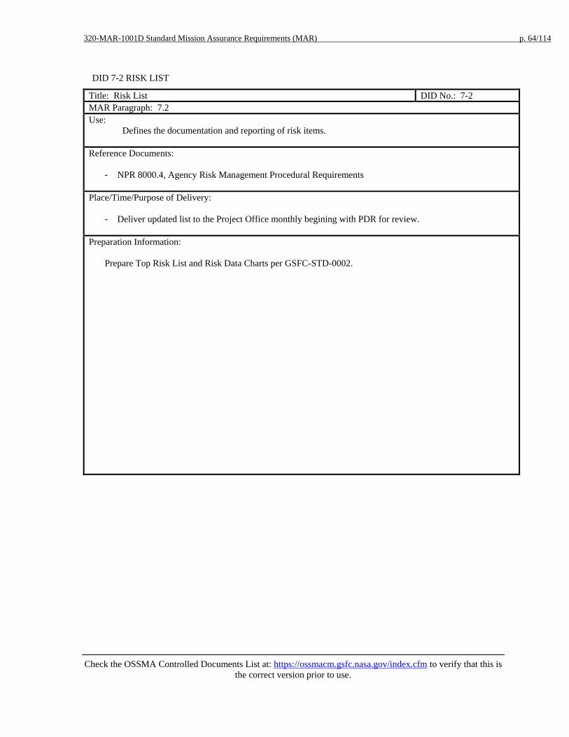
320-MAR-1001D Standard Mission Assurance Requirements (MAR) p. 64/114
Check the OSSMA Controlled Documents List at: https://ossmacm.gsfc.nasa.gov/index.cfm to verify that this is
the correct version prior to use.
DID 7-2 RISK LIST
Title: Risk List DID No.: 7-2 MAR Paragraph: 7.2 Use:
Defines the documentation and reporting of risk items.
Reference Documents:
- NPR 8000.4, Agency Risk Management Procedural Requirements
Place/Time/Purpose of Delivery:
- Deliver updated list to the Project Office monthly begining with PDR for review.
Preparation Information:
Prepare Top Risk List and Risk Data Charts per GSFC-STD-0002.

320-MAR-1001D Standard Mission Assurance Requirements (MAR) p. 65/114
Check the OSSMA Controlled Documents List at: https://ossmacm.gsfc.nasa.gov/index.cfm to verify that this is
the correct version prior to use.
DID 8-1 SYSTEMS REVIEW MATERIALS
Title: Systems Review Materials DID No.: 8-1 MAR Paragraph: 8.1 Use:
To provide the systems review team with the materials used to conduct the review. Reference Documents
- Project Systems Review Plan - GSFC-STD-1001 Criteria for Flight Project Critical Milestone Reviews - NPR 7120.5 NASA Space Flight Program and Project Management Requirements, Section 2.5 - NPR 7123.1 NASA Systems Engineering Processes and Requirements, Chapter 5
Place/Time/Purpose of Delivery:
- Provide the review agenda to the Project Office fourteen (14) days prior to commencement of the review for information.
- Provide the review presentation materials to the Project Office seven (7) days prior to the review for information.
- Provide review related reference materials to the Project Office at the review for information. Preparation Information:
See the guidelines presented in the reference documents.

320-MAR-1001D Standard Mission Assurance Requirements (MAR) p. 66/114
Check the OSSMA Controlled Documents List at: https://ossmacm.gsfc.nasa.gov/index.cfm to verify that this is
the correct version prior to use.
DID 8-2 ACTION ITEM RESPONSES
Title: Action Item Responses DID No.: 8-2 MAR Paragraph: 8.1 Use:
To respond to action items resulting from the review. Reference Documents
- Project Systems Review Plan (provided by Project Office) - GSFC-STD-1001 Criteria for Flight Project Critical Milestone Reviews
Place/Time/Purpose of Delivery:
- Provide response to action items to the Project Office thirty (30) days after end of review for approval Preparation Information:
See the guidelines presented in the related documents.

320-MAR-1001D Standard Mission Assurance Requirements (MAR) p. 67/114
Check the OSSMA Controlled Documents List at: https://ossmacm.gsfc.nasa.gov/index.cfm to verify that this is
the correct version prior to use.
DID 8-3 ENGINEERING PEER REVIEW PROGRAM
Title: Engineering Peer Review Program DID No.: 8-3 MAR Paragraph: 8.2 Use:
To define the plan for conducting the developer's engineering peer review program.
Reference Documents
- GPR 8700.6 Engineering Peer Reviews Place/Time/Purpose of Delivery:
- Provide to the Project Office sixty (60) days after contract award for review. Preparation Information:
See the guidelines presented in the reference document.

320-MAR-1001D Standard Mission Assurance Requirements (MAR) p. 68/114
Check the OSSMA Controlled Documents List at: https://ossmacm.gsfc.nasa.gov/index.cfm to verify that this is
the correct version prior to use.
DID 9-1 SYSTEM PERFORMANCE VERIFICATION PLAN
Title: System Performance Verification Plan DID No.: 9-1 MAR Paragraph: 9.1 Use:
Establishes the System Performance Verification Plan.
Reference Documents:
- GSFC-STD-7000 General Environmental Verification Standard (GEVS) for GSFC Flight Programs and Projects
Place/Time/Purpose of Delivery:
- Provide preliminary plan to Project Office thirty (30) days prior to PDR for review. - Provide final plan to Project Office thirty (30) days prior to CDR for approval.
Preparation Information:
The System Performance Verification Plan shall be prepared to comply with the requirements of paragraph 2.1.1.1 of GSFC-STD-7000.

320-MAR-1001D Standard Mission Assurance Requirements (MAR) p. 69/114
Check the OSSMA Controlled Documents List at: https://ossmacm.gsfc.nasa.gov/index.cfm to verify that this is
the correct version prior to use.
DID 9-2 ENVIRONMENTAL VERIFICATION PLAN
Title: Environmental Verification Plan DID No.: 9-2 MAR Paragraph: 9.2 Use:
Establishes the Environmental Verification Plan.
Reference Documents:
- GSFC-STD-7000 General Environmental Verification Standard (GEVS) for GSFC Flight Programs and Projects
Place/Time/Purpose of Delivery:
- Provide preliminary plan to Project Office thirty (30) days prior to PDR for review. - Provide final plan to Project Office thirty (30) days prior to CDR for approval.
Preparation Information:
The Environmental Verification Plan shall be prepared to comply with the requirements of paragraph 2.1.1.1.1 of GSFC-STD-7000.

320-MAR-1001D Standard Mission Assurance Requirements (MAR) p. 70/114
Check the OSSMA Controlled Documents List at: https://ossmacm.gsfc.nasa.gov/index.cfm to verify that this is
the correct version prior to use.
DID 9-3 SYSTEM PERFORMANCE VERIFICATION MATRIX
Title: System Performance Verification Matrix DID No.: 9-3 MAR Paragraph: 9.3 Use:
Establishes the System Performance Verification Matrix. Reference Documents:
- GSFC-STD-7000 General Environmental Verification Standard (GEVS) for GSFC Flight Programs and Projects
Place/Time/Purpose of Delivery:
- The updated System Performance Verification Matrix shall be included in the data packages for the Integrated Independent Reviews, beginning with PDR, for review
Preparation Information:
The System Performance Verification Matrix shall be prepared and maintained per the requirements of paragraph 2.1.1.2 of GSFC-STD-7000.

320-MAR-1001D Standard Mission Assurance Requirements (MAR) p. 71/114
Check the OSSMA Controlled Documents List at: https://ossmacm.gsfc.nasa.gov/index.cfm to verify that this is
the correct version prior to use.
DID 9-4 ENVIRONMENTAL TEST MATRIX
Title: Environmental Test Matrix DID No.: 9-4 MAR Paragraph: 9.4 Use:
Establishes a matrix that summarizes the environmental tests and test status for flight hardware and other equipment.
Reference Documents:
- GSFC-STD-7000 General Environmental Verification Standard (GEVS) for GSFC Flight Programs and Projects
Place/Time/Purpose of Delivery:
- The updated matrix shall be included with the review data package for milestone reviews beginning with PDR for review.
Preparation Information:
Guidelines for environmental test matrices are in paragraph 2.1.1.2.1 of GSFC-STD-7000. An example of an environmental test matrix is given in Figure 2.1-1
.

320-MAR-1001D Standard Mission Assurance Requirements (MAR) p. 72/114
Check the OSSMA Controlled Documents List at: https://ossmacm.gsfc.nasa.gov/index.cfm to verify that this is
the correct version prior to use.
DID 9-5 VERIFICATION REPORTS
Title: Verification Reports DID No.: 9-5 MAR Paragraph: 9.5 Use:
Establishes the requirement to submit Verification Reports Reference Documents:
- GSFC-STD-7000 General Environmental Verification Standard (GEVS) for GSFC Flight Programs and Projects
Place/Time/Purpose of Delivery:
- Preliminary verification report shall be provided to Project Office within seventy-two (72) hours of test completion for information.
- Final verification report shall be provided to Project Office within thirty (30) days of test completion for information.
Preparation Information:
The Verification Reports shall be prepared to comply with the requirements of paragraph 2.1.1.5 of GSFC-STD-7000.

320-MAR-1001D Standard Mission Assurance Requirements (MAR) p. 73/114
Check the OSSMA Controlled Documents List at: https://ossmacm.gsfc.nasa.gov/index.cfm to verify that this is
the correct version prior to use.
DID 9-6 SYSTEM PERFORMANCE VERIFICATION REPORT
Title: System Performance Verification Report DID No.: 9-6 MAR Paragraph: 9.6 Use:
Establishes a Performance Verification Report that compares hardware/software specifications with the final verified values.
Reference Documents:
- GSFC-STD-7000 General Environmental Verification Standard (GEVS) for GSFC Flight Programs and Projects
Place/Time/Purpose of Delivery:
- Updated reports shall be provided with the review data package at milestone reviews, beginning with CDR, for information
- The final report shall be submitted within thirty (30) days after completion of on-orbit checkout for information
Preparation Information:
The System Performance Verification Report shall be prepared and maintained per paragraph 2.1.1.6 of GSFC-STD-7000.

320-MAR-1001D Standard Mission Assurance Requirements (MAR) p. 74/114
Check the OSSMA Controlled Documents List at: https://ossmacm.gsfc.nasa.gov/index.cfm to verify that this is
the correct version prior to use.
DID 10-1 ESD CONTROL PLAN
Title: ESD Control Plan DID No.: 10-1 MAR Paragraph: 10.4 Use:
Implementation of an ESD control program at the developer’s facility
Reference Documents:
- ANSI/ESD S20.20 For the Development of an Electrostatic Discharge Control Program for Protection of Electrical and Electronic Parts, Assemblies and Equipment (Excluding Electrically Initiated Explosive Devices)
Place/Time/Purpose of Delivery:
- The developer shall submit an ESD Control Plan to the Project thirty (30) days prior to PDR for review. Preparation Information:
The ESD Control Plan shall be prepared and implemented to comply with ANSI/ESD S20.20 requirements and the ESD sensitivity of the product being developed.

320-MAR-1001D Standard Mission Assurance Requirements (MAR) p. 75/114
Check the OSSMA Controlled Documents List at: https://ossmacm.gsfc.nasa.gov/index.cfm to verify that this is
the correct version prior to use.
DID 11-1: PARTS CONTROL PLAN (PCP) Title: Parts Control Plan DID No.: 11-1 MAR Paragraph: 11.1 Use:
Development and implementation of an EEE parts control plan that addresses the system requirements for mission lifetime and reliability.
Reference Documents
- GSFC EEE-INST-002 Instructions for EEE Parts Selection, Screening, Qualification, and Derating - S-311-M-70 Specification for Destructive Physical Analysis - SAE AS5553 Counterfeit Electronic Parts; Avoidance, Detection, Mitigation, and Disposition
Place/Time/Purpose of Delivery:
- The developer shall submit the PCP to the project office thirty (30) days after contract award for approval. Preparation Information:
The PCP shall address the following: - Parts control program organization and management - Shelf life control plan - Parts application derating - Supplier and manufacturer surveillance - Qualification - Procedures regarding application specific integrated circuits, gate arrays, system-on-chip, and custom
integrated circuits - Incoming inspection and test - Sparing policies - Destructive physical analysis - Defective parts controls program. - Handling, preservation, and packing - Contamination control - Alternate quality conformance inspection and small lot sampling - Traceability and lot control - Failure analysis - Counterfeit parts control plan per AS5553 - Radiation hardness assurance program, which shall address: total ionizing dose; displacement damage
(total non-ionizing dose); destructive and non-destructive single-event effects; single-event effect rates; proton hardness/tolerance

320-MAR-1001D Standard Mission Assurance Requirements (MAR) p. 76/114
Check the OSSMA Controlled Documents List at: https://ossmacm.gsfc.nasa.gov/index.cfm to verify that this is
the correct version prior to use.
DID 11-2: PARTS CONTROL BOARD (PCB) Title: Parts Control Board DID No.: 11-2 MAR Paragraph: 11.2 Use:
Organization and operation of the Parts Control Board regarding the implementation of the Parts Control Program.
Reference Documents: Place/Time/Purpose of Delivery:
- The developer shall submit the Parts Control Board operating procedures to the project office thirty (30) days after contract award for approval.
Preparation Information:
The developer shall address the following in the Parts Control Board procedures: - Organization and membership - Meeting schedule - Meeting notices - Distribution of meeting agenda, notes, and minutes - Review and approval responsibilities and processes

320-MAR-1001D Standard Mission Assurance Requirements (MAR) p. 77/114
Check the OSSMA Controlled Documents List at: https://ossmacm.gsfc.nasa.gov/index.cfm to verify that this is
the correct version prior to use.
DID 11-3: PARTS IDENTIFICATION LIST Title: Parts Identification List (PIL) DID No.: 11-3 MAR Paragraph: 11.3.1 Use:
A list of EEE parts that may be selected for use in flight hardware. Reference Documents: Place/Time/Purpose of Delivery:
- The developer shall submit EEE parts to be added to the PIL to the Parts Control Board ten (10) business days prior to the first PCB meeting for approval by the PCB
Preparation Information:
The Parts Identification List shall contain the following information in a searchable electronic format: - Flight component identity to the circuit board level - Complete part number (i.e. Defense Supply Center Columbus part number, Specification Control Drawing
part number, with all suffixes) - Manufacturer’s Generic Part number - Manufacturer (not distributor) - Part Description (please include meaningful detail) - Federal Supply Class - Procurement Specification - Comments and clarifications, as appropriate - Estimated quantity required (for procurement forecasting)

320-MAR-1001D Standard Mission Assurance Requirements (MAR) p. 78/114
Check the OSSMA Controlled Documents List at: https://ossmacm.gsfc.nasa.gov/index.cfm to verify that this is
the correct version prior to use.
DID 11-4: PROJECT APPROVED PARTS LIST Title: Project Approved Parts List (PAPL) DID No.: 11-4 MAR Paragraph: 11.3.2 Use:
A list of EEE parts that are approved by the Parts Control Board for use in flight hardware. Reference Documents: Place/Time/Purpose of Delivery:
- The developer shall submit EEE parts to be added to the Project Approved Parts List to the Parts Control Board ten (10) business days prior to the PCB meeting at which they will be presented for approval by the PCB
Preparation Information:
The PAPL shall contain all PIL fields plus the following information in a searchable electronic format: - Procurement Part Number - Flight Part Number (if different from the procurement part number) - Package Style/Designation - Single Event Latch-up (SEL) Hardness/Tolerance and Data Source - Single Event Upset (SEU) Hardness/Tolerance and Data Source - Total Ionizing Dose (TID) Hardness/Tolerance and Data Source - Displacement Damage Hardness/Tolerance (total non-ionizing dose) and Data Source - Proton Hardness/Tolerance and Data Source - PCB Status - PCB Approval Date - PCB Required Testing/Evaluations

320-MAR-1001D Standard Mission Assurance Requirements (MAR) p. 79/114
Check the OSSMA Controlled Documents List at: https://ossmacm.gsfc.nasa.gov/index.cfm to verify that this is
the correct version prior to use.
DID 11-5: AS DESIGNED PARTS LIST Title: As Designed Parts List (ADPL) DID No.: 11-5 MAR Paragraph: 11.3.3 Use:
A list of EEE parts that are designed into in flight hardware. Reference Documents
Place/Time/Purpose of Delivery:
- The developer shall submit EEE Parts to be added to the As Designed Parts List to the Parts Control Board ten (10) business days prior to the PCB meeting at which they will be presented for approval by the PCB
Preparation Information:
The As Designed Parts List (ADPL) shall contain all PAPL fields plus the following information in a searchable electronic format: - Assembly Name/Number - Next Level of Assembly - Need Quantity - Reference Designator(s) - Item number (if applicable)

320-MAR-1001D Standard Mission Assurance Requirements (MAR) p. 80/114
Check the OSSMA Controlled Documents List at: https://ossmacm.gsfc.nasa.gov/index.cfm to verify that this is
the correct version prior to use.
DID 11-6: AS BUILT PARTS LIST Title: As Built Parts List (ABPL) DID No.: 11-6 MAR Paragraph: 11.3.4 Use:
A list of EEE parts that are used in the flight hardware. Reference Documents
Place/Time/Purpose of Delivery:
- The developer shall submit EEE Parts to be added to the As Built Parts List to the Parts Control Board ten (10) business days prior to the PCB meeting at which they will be reviewed by the PCB
Preparation Information:
The As Built Parts List (ABPL): shall contain all ADPL fields plus the following information in a searchable electronic format: - Assembly serial number - Item revision - Next Level of Assembly serial number - Lot/Date/Batch/Heat/Manufacturing Code, as applicable - Manufacturer’s Cage Code (specific plant location when relevant) - Distributor/supplier, if applicable - Part number - Part serial number (if applicable)

320-MAR-1001D Standard Mission Assurance Requirements (MAR) p. 81/114
Check the OSSMA Controlled Documents List at: https://ossmacm.gsfc.nasa.gov/index.cfm to verify that this is
the correct version prior to use.
DID 12-1 MATERIALS AND PROCESSES SELECTION, CONTROL, & IMPLEMENTATION PLAN
Title: Materials and Processes Selection, Control, & Implementation Plan DID No.: 12-1 MAR Paragraph: 12.1 Use:
Defines the implementation of NASA-STD-6016 with prescribed changes as described in the Preparation Information.
Reference Documents:
NASA-STD-6016 Standard Materials and Processes Requirement for Spacecraft
Place/Time/Purpose of Delivery:
- Provide to the Project Office sixty (60) days after contract award for approval.
Preparation Information:
For each paragraph in Section 4 of NASA-STD-6016, with the changes prescribed below, the plan shall state the requirement from NASA-STD-6016, identify the degree of conformance under the subheading "Degree of Conformance," and identify the method of implementation under the subheading "Method of Implementation."
The plan shall address the following: - Conformance to the requirements of NASA-STD-6016 with the changes prescribed below and a
description of the method of implementation. - Organizational authority and responsibility for review and approval of M&P specified prior to release of
engineering documentation. - Identification and documentation of Materials and Processes - Procedures and data documentation for proposed test programs to support materials screening and
verification testing - Materials Usage Agreement (MUA) Procedures - Determination of material design properties, including statistical approaches to be employed. - Identification of process specifications used to implement requirements in NASA-STD-6016. - In addition to the requirements of paragraph 4.2.2.11, the developer shall meet the requirements of
GEIA-STD-0005-1 and GEIA-STD-0005-2 for solders and surface finishes that are less than 3% lead by weight. The LFCP shall comply with the Level "2C" requirements set.
- In paragraph 4.1.2, the developer may use GFSC forms or the developer’s equivalent forms in lieu of the MAPTIS format.
- The developer may use the GSFC outgassing database in addition to MAPTIS (URL http://outgassing.nasa.gov).
Prescribed changes to NASA-STD-6016: - The developer shall use the NASA-STD-8719.24 NASA Expendable Launch Vehicle Payload Safety
Requirements Table in place of paragraph 4.2.1. - In addition to the requirements of paragraph 4.2.3.4, the developer shall qualify all lubricated
mechanisms either by life testing in accordance with a life test plan or heritage with an identical mechanism used in an identical application. The developer shall perform a lubricant loss analysis for all mechanisms to show that the design meets a 10X margin (see DID 12-2).
- In addition to the requirements of paragraph 4.2.3.6, the developer shall provide the vacuum bake out schedule for materials that fail outgassing requirements with the MIUL or MUA.
- Paragraph 4.2.3.8 does not apply. - In paragraph 4.2.5.1, the developer shall develop and implement a Non-Destructive Evaluation Plan only
for fracture critical flight hardware (see DID 12-5).

320-MAR-1001D Standard Mission Assurance Requirements (MAR) p. 82/114
Check the OSSMA Controlled Documents List at: https://ossmacm.gsfc.nasa.gov/index.cfm to verify that this is
the correct version prior to use.
- In paragraph 4.2.6.5, the developer shall use 541-PG-8072.1.2 GSFC Fastener Specification in place of NASA-STD-6008.
- Paragraph 4.2.6.6 does not apply.

320-MAR-1001D Standard Mission Assurance Requirements (MAR) p. 83/114
Check the OSSMA Controlled Documents List at: https://ossmacm.gsfc.nasa.gov/index.cfm to verify that this is
the correct version prior to use.
DID 12-2 Life Test Plan for Lubricated Mechanisms Title: Life Test Plan for Lubricated Mechanisms DID No.: 12-2 MAR Paragraph: 12.2
Use:
Defines the life test evaluation process, acceptance criteria, and reporting for lubricated mechanisms.
Reference Documents:
- NASA-STD-6016 Standard Materials and Processes Requirement for Spacecraft - NASA-TM-86556 Lubrication Handbook for the Space Industry (Part A: Solid Lubricants, Part B:
Liquid Lubricants) - NASA/CR-2005-213424 Lubrication for Space Applications
Place/Time/Purpose of Delivery:
- Provide plan to the Project thirty (30) days prior to PDR for approval. - Provide report to the Project thirty (30) days after acceptance test completion for review.
Preparation Information:
The Life Test Plan for Lubricated Mechanisms shall contain: - Table of Contents - Description of lubricated mechanisms, performance functions, summary of subsystem specification, and
life requirements. - Heritage of identical mechanisms and descriptions of identical applications. - Design, drawings, and lubrication system used by the mechanism. - Test plan, including vacuum, temperature, and vibration test environmental conditions. - Criteria for a successful test. - Final report.

320-MAR-1001D Standard Mission Assurance Requirements (MAR) p. 84/114
Check the OSSMA Controlled Documents List at: https://ossmacm.gsfc.nasa.gov/index.cfm to verify that this is
the correct version prior to use.
DID 12-3 MATERIALS USAGE AGREEMENT
Title: Materials Usage Agreement (MUA) DID No.: 12-3 MAR Paragraph: 12.3 Use:
Establishes the process for submitting a MUA for a material or process that does not meet the requirements of NASA-STD-6016 and does not affect reliability or safety when used per the Materials and Processes Selection, Control, and Implementation Plan.
Reference Documents:
- NASA-STD-6016 Standard Materials and Processes Requirement for Spacecraft - MSFC-STD-3029 Guidelines for the Selection of Metallic Materials for Stress Corrosion Cracking
Resistance in Sodium Chloride Environments
Place/Time/Purpose of Delivery:
- Provide new MUAs to the Project thirty (30) days prior to CDR for approval. - After the initial submission of MUAs, revised MUAs shall be provided to the Project within thirty (30)
days of their identification for approval.
Preparation Information:
The MUA system shall be defined in the Materials and Processes Selection, Control, and Implementation Plan as approved per paragraph 1.2 (see DID 12-1). The MUA package shall include the technical information required to justify the application. MUAs for stress corrosion shall include a Stress Corrosion Cracking Evaluation Form per MSFC-STD-3029 (see NASA-STD-6016) and a stress analysis.

320-MAR-1001D Standard Mission Assurance Requirements (MAR) p. 85/114
Check the OSSMA Controlled Documents List at: https://ossmacm.gsfc.nasa.gov/index.cfm to verify that this is
the correct version prior to use.
DID 12-4 MATERIALS IDENTIFICATION AND USAGE LIST
Title: Materials Identification and Usage List (MIUL) DID No.: 12-4 MAR Paragraph: 12.4 Use:
Establishes the Materials Identification and Usage List (MIUL).
Reference Documents:
- NASA-STD-6016 Standard Materials and Processes Requirement for Spacecraft
Place/Time/Purpose of Delivery:
- Provide to the Project Office thirty (30) days prior to PDR for review - Provide to the Project Office thirty (30) days prior to CDR approval - Provide updates to the Project Office within thirty (30) days of identification for review
Preparation Information:
The MIUL documenation approach shall be defined in the Materials and Processes Selection, Control, and Implementation Plan as approved per paragraph 1.2 (see DID 12-1).

320-MAR-1001D Standard Mission Assurance Requirements (MAR) p. 86/114
Check the OSSMA Controlled Documents List at: https://ossmacm.gsfc.nasa.gov/index.cfm to verify that this is
the correct version prior to use.
DID 12-5 NONDESTRUCTIVE EVALUATION PLAN
Title: Nondestructive Evaluation Plan DID No.: 12-5 MAR Paragraph: 12.5 Use:
Establishes the Non-Destructive Evaluation (NDE) plan for the procedures and specifications employed in the inspection of materials.
Reference Documents:
- NASA-STD-6016 Standard Materials and Processes Requirement for Spacecraft - MIL-HDBK-6870, Inspection Program Requirements, Nondestructive for Aircraft and Missile Materials
and Parts - NASA-STD-5009 Nondestructive Evaluation Requirements for Fracture-Critical Metallic Components
Place/Time/Purpose of Delivery:
- Provide to the Project thirty (30) days prior to PDR for review. - Provide to the Project thirty (30) days prior to CDR for approval. - Provide updates to the Project thirty (30) days after identification for approval.
Preparation Information:
The NDE Plan shall describe the process for establishment, implementation, execution and control of NDE. The plan shall meet the intent of MIL-HDBK-6870, Inspection Program Requirements, Nondestructive for Aircraft and Missile Materials and Parts and NASA-STD-5009 Nondestructive Evaluation Requirements for Fracture-Critical Metallic Components, as specified by NASA-STD-6016. The plan shall define NDT planning and requirements to include the following: - Hardware Design - Manufacturing Planning - Personnel Training - NDE Reliability Requirements for Fracture Critical Parts - NDE Reporting

320-MAR-1001D Standard Mission Assurance Requirements (MAR) p. 87/114
Check the OSSMA Controlled Documents List at: https://ossmacm.gsfc.nasa.gov/index.cfm to verify that this is
the correct version prior to use.
DID 12-6 PRINTED WIRING BOARDS TEST COUPONS
Title: Printed Wiring Board (PWB) Test Coupons DID No.: 12-6 MAR Paragraph: 12.6 Use:
PWB test coupons are evaluated to validate that PWBs are suitable for use in space flight and mission critical ground applications.
Reference Documents:
- IPC-6011 Generic Performance Specifications for Printed Boards (Class 3 Requirements) - IPC-6012B Qualification and Performance Specification for Rigid Printed Boards (Class 3/A
Requirements /Performance Specification Sheet for Space and Military Avionics) - IPC-6013 Qualification and Performance Specification for Flexible Printed Boards (Class 3 ) - IPC-6018 Microwave End Product Board Inspection and Test - IPC A-600 Guidelines for Acceptability of Printed Boards (Class 3 Requirements)
Place/Time/Purpose of Delivery:
- The developer shall deliver test coupons and supporting manufacturing information traceable to the flight boards to GSFC or a GSFC-approved laboratory as soon as practicable for analysis of the printed wiring boards for approval.
- In the case that a GSFC-approved laboratory is used, the developer shall deliver the laboratory results to GSFC with the end item data package.
Preparation Information:
Notify GSFC regarding shipment of PWB test coupons.

320-MAR-1001D Standard Mission Assurance Requirements (MAR) p. 88/114
Check the OSSMA Controlled Documents List at: https://ossmacm.gsfc.nasa.gov/index.cfm to verify that this is
the correct version prior to use.
DID 13-1 CONTAMINATION CONTROL PLAN AND DATA
Title: Contamination Control Plan and Data DID No.: 13-1 MAR Paragraph: 13.1 Use:
To establish contamination allowances, methods for controlling contamination, and record test results
Reference Documents:
- GSFC-STD-7000 General Environmental Verification Standard (GEVS) - GSFC-STD-1000 Rules for the Design, Development, Verification, and Operation of Flight Systems - ASTM E595 Standard Test Methods for Total Mass Loss and Collected Volatile Condensable Materials
from Outgassing in a Vacuum Environment - Outgassing Data for Selecting Spacecraft Materials (URL: http://outgassing.nasa.gov/)
Place/Time/Purpose of Delivery:
- Provide to the Project Office thirty (30) days before PDR for GSFC review. - Provide to the Project Office thirty (30) days before the CDR for approval. - Final thermal vacuum bakeout results provided to the Project Office within thirty (30) of completion for
review. - Provide contamination certificate of compliance with End Item Acceptance Data Package (DID 16-1) for
review
Preparation Information:
The developer shall provide: material properties data; design features; test data; system tolerance of degraded performance; methods to prevent degradation. The items below shall be addressed in the plan: - Beginning of life and end of life requirements for contamination sensitive surfaces or subsystems - Methods and procedures used to measure and maintain the levels of cleanliness required during each of
the various phases of the item’s lifetime (e.g., protective covers, environmental constraints, purges, cleaning/monitoring procedures)
- Materials - Outgassing as a function of temperature and time. - Nature of outgassing chemistry. - Areas, weight, location, view factors of critical surfaces.
- Venting: size, location and relation to external surfaces. - Thermal vacuum test contamination monitoring plan, to include vacuum test data, QCM location and
temperature, pressure data, system temperature profile, and shroud temperature. - On-orbit spacecraft and instrument performance as affected by contamination deposits.
- Contamination effect monitor - Methods to prevent and recover from contamination in orbit - Evaluation of on-orbit degradation - Photopolymerization of outgassing products on critical surfaces - Space debris risks and protection - Atomic oxygen erosion and re-deposition
- Analysis of contamination impact on the satellite on orbit performance - In orbit contamination impact from other sources such as STS, space station, and adjacent instruments - Ground/Test support equipment controls to prevent contamination of flight item(s) - Facility controls and processes to maintain hardware integrity (protection and avoidance) - Training - Data package on test results for materials and as-built product
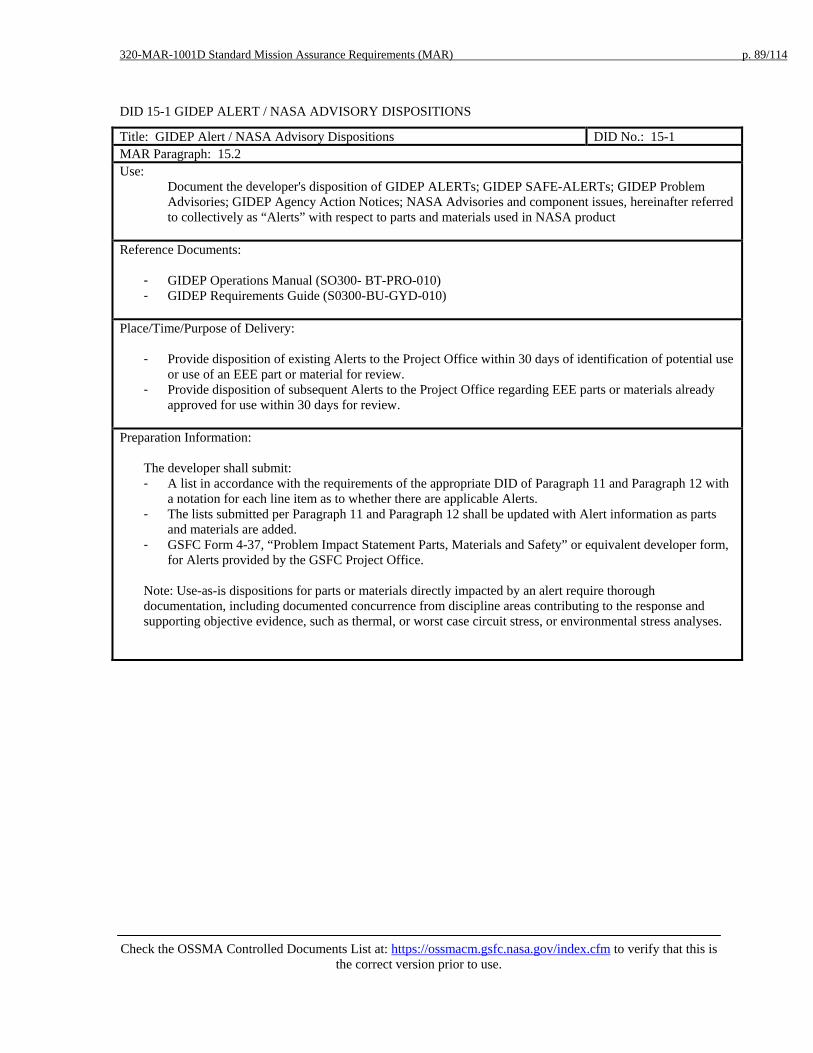
320-MAR-1001D Standard Mission Assurance Requirements (MAR) p. 89/114
Check the OSSMA Controlled Documents List at: https://ossmacm.gsfc.nasa.gov/index.cfm to verify that this is
the correct version prior to use.
DID 15-1 GIDEP ALERT / NASA ADVISORY DISPOSITIONS
Title: GIDEP Alert / NASA Advisory Dispositions DID No.: 15-1 MAR Paragraph: 15.2 Use:
Document the developer's disposition of GIDEP ALERTs; GIDEP SAFE-ALERTs; GIDEP Problem Advisories; GIDEP Agency Action Notices; NASA Advisories and component issues, hereinafter referred to collectively as “Alerts” with respect to parts and materials used in NASA product
Reference Documents:
- GIDEP Operations Manual (SO300- BT-PRO-010) - GIDEP Requirements Guide (S0300-BU-GYD-010)
Place/Time/Purpose of Delivery:
- Provide disposition of existing Alerts to the Project Office within 30 days of identification of potential use or use of an EEE part or material for review.
- Provide disposition of subsequent Alerts to the Project Office regarding EEE parts or materials already approved for use within 30 days for review.
Preparation Information:
The developer shall submit: - A list in accordance with the requirements of the appropriate DID of Paragraph 11 and Paragraph 12 with
a notation for each line item as to whether there are applicable Alerts. - The lists submitted per Paragraph 11 and Paragraph 12 shall be updated with Alert information as parts
and materials are added. - GSFC Form 4-37, “Problem Impact Statement Parts, Materials and Safety” or equivalent developer form,
for Alerts provided by the GSFC Project Office.
Note: Use-as-is dispositions for parts or materials directly impacted by an alert require thorough documentation, including documented concurrence from discipline areas contributing to the response and supporting objective evidence, such as thermal, or worst case circuit stress, or environmental stress analyses.

320-MAR-1001D Standard Mission Assurance Requirements (MAR) p. 90/114
Check the OSSMA Controlled Documents List at: https://ossmacm.gsfc.nasa.gov/index.cfm to verify that this is
the correct version prior to use.
DID 15-2 SIGNIFICANT PARTS, MATERIALS, AND SAFETY PROBLEMS
Title: Significant parts, materials, and safety problems DID No.: 15-2 MAR Paragraph: 15.3 Use:
Document the developer's identification of significant parts, material, and safety problems and the developer’s actions as required by the GIDEP manual regarding the decision to prepare an Alert, including the type of Alert that is applicable.
Reference Documents:
- GIDEP Operations Manual (SO300- BT-PRO-010) - GIDEP Requirements Guide (S0300-BU-GYD-010)
Place/Time/Purpose of Delivery:
- Deliver to the Project Office within thirty (30) days of identification for review. Preparation Information:
The developer shall submit relevant information (e.g., failure analyses, test reports, root cause and corrective action evaluations).
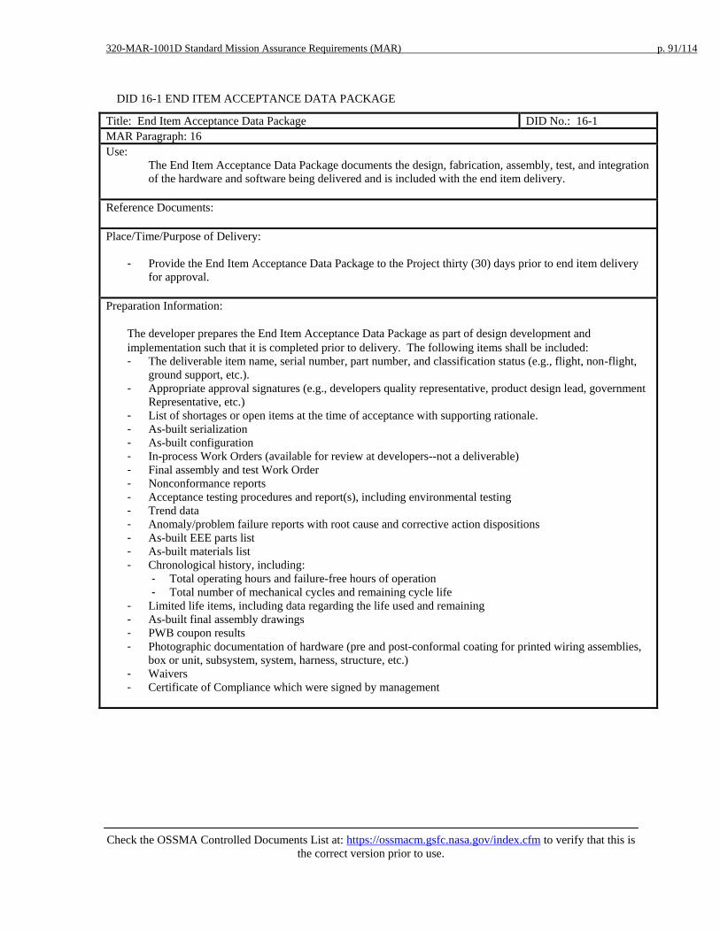
320-MAR-1001D Standard Mission Assurance Requirements (MAR) p. 91/114
Check the OSSMA Controlled Documents List at: https://ossmacm.gsfc.nasa.gov/index.cfm to verify that this is
the correct version prior to use.
DID 16-1 END ITEM ACCEPTANCE DATA PACKAGE
Title: End Item Acceptance Data Package DID No.: 16-1 MAR Paragraph: 16 Use:
The End Item Acceptance Data Package documents the design, fabrication, assembly, test, and integration of the hardware and software being delivered and is included with the end item delivery.
Reference Documents: Place/Time/Purpose of Delivery:
- Provide the End Item Acceptance Data Package to the Project thirty (30) days prior to end item delivery for approval.
Preparation Information:
The developer prepares the End Item Acceptance Data Package as part of design development and implementation such that it is completed prior to delivery. The following items shall be included: - The deliverable item name, serial number, part number, and classification status (e.g., flight, non-flight,
ground support, etc.). - Appropriate approval signatures (e.g., developers quality representative, product design lead, government
Representative, etc.) - List of shortages or open items at the time of acceptance with supporting rationale. - As-built serialization - As-built configuration - In-process Work Orders (available for review at developers--not a deliverable) - Final assembly and test Work Order - Nonconformance reports - Acceptance testing procedures and report(s), including environmental testing - Trend data - Anomaly/problem failure reports with root cause and corrective action dispositions - As-built EEE parts list - As-built materials list - Chronological history, including:
- Total operating hours and failure-free hours of operation - Total number of mechanical cycles and remaining cycle life
- Limited life items, including data regarding the life used and remaining - As-built final assembly drawings - PWB coupon results - Photographic documentation of hardware (pre and post-conformal coating for printed wiring assemblies,
box or unit, subsystem, system, harness, structure, etc.) - Waivers - Certificate of Compliance which were signed by management

320-MAR-1001D Standard Mission Assurance Requirements (MAR) p. 92/114
Check the OSSMA Controlled Documents List at: https://ossmacm.gsfc.nasa.gov/index.cfm to verify that this is
the correct version prior to use.
Appendix 4. MAR Response Form Note: Delete one of the two entries in paragraph 3.3.3 and DID 3.7 of this table to correspond with the tayloring selection made for Paragraph 3.3.3 of the MAR.
• Enter Yes or No regarding compliance with the requirements. • A response of Yes indicates full compliance with the requirements. The Comment
column should be used as required to indicate how compliance will be achieved, e.g., through an equivalent procedure.
• A response of No indicates less than full compliance with the requirements and requires an entry in the Comment column to explain the deviation from full compliance.
Paragraph
or DID Title
Comply Y / N
Comment (Required for No)
1 General
1.1 Systems Safety and Mission Assurance Program
1.2 Management
1.3 Requirements Flowdown
1.4 Suspension of Work Activities
1.5 Contract Data Requirements List
1.6 Surveillance
1.7 Use of Previously Developed Product
DID 1-1 Mission Assurance Implementation Plan
DID 1-2 Previously Developed Product – Compliance with Requirements
2 Quality Management System
2.1 General
2.2 Supplemental Quality Management System Requirements
2.2.1 Control of Nonconforming Product
2.2.2 Material Review Board 2.2.3 Anomaly Reporting and
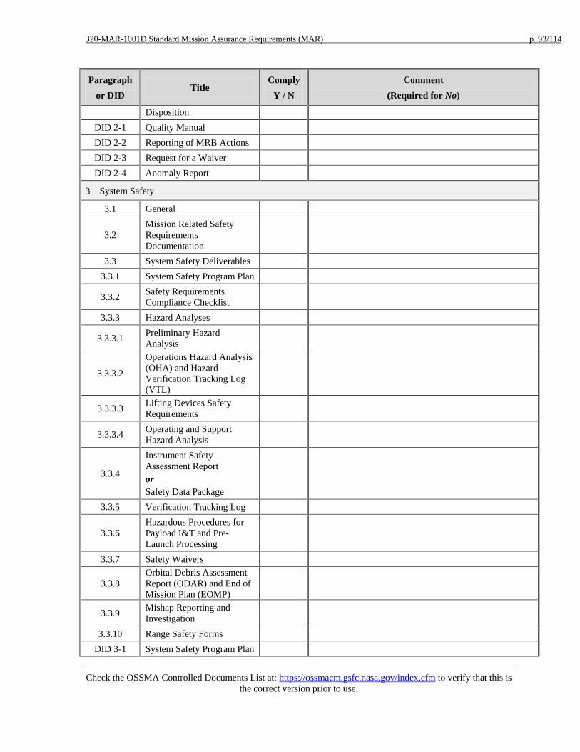
320-MAR-1001D Standard Mission Assurance Requirements (MAR) p. 93/114
Check the OSSMA Controlled Documents List at: https://ossmacm.gsfc.nasa.gov/index.cfm to verify that this is
the correct version prior to use.
Paragraph or DID
Title Comply
Y / N Comment
(Required for No)
Disposition DID 2-1 Quality Manual DID 2-2 Reporting of MRB Actions DID 2-3 Request for a Waiver DID 2-4 Anomaly Report
3 System Safety
3.1 General
3.2 Mission Related Safety Requirements Documentation
3.3 System Safety Deliverables 3.3.1 System Safety Program Plan
3.3.2 Safety Requirements Compliance Checklist
3.3.3 Hazard Analyses
3.3.3.1 Preliminary Hazard Analysis
3.3.3.2
Operations Hazard Analysis (OHA) and Hazard Verification Tracking Log (VTL)
3.3.3.3 Lifting Devices Safety Requirements
3.3.3.4 Operating and Support Hazard Analysis
3.3.4
Instrument Safety Assessment Report or Safety Data Package
3.3.5 Verification Tracking Log
3.3.6 Hazardous Procedures for Payload I&T and Pre-Launch Processing
3.3.7 Safety Waivers
3.3.8 Orbital Debris Assessment Report (ODAR) and End of Mission Plan (EOMP)
3.3.9 Mishap Reporting and Investigation
3.3.10 Range Safety Forms DID 3-1 System Safety Program Plan

320-MAR-1001D Standard Mission Assurance Requirements (MAR) p. 94/114
Check the OSSMA Controlled Documents List at: https://ossmacm.gsfc.nasa.gov/index.cfm to verify that this is
the correct version prior to use.
Paragraph or DID
Title Comply
Y / N Comment
(Required for No)
DID 3-2 Safety Requirements Compliance Checklist
DID 3-3 Preliminary Hazard Analysis
DID 3-4 Operations Hazard Analysis
DID 3-5 Safety Hazard Analysis on Critical Lift Equipment
DID 3-6 Operating and Support Hazard Analysis
DID 3-7 Instrument Safety Assessment Report or Safety Data Package
DID 3-8 Verification Tracking Log
DID 3-9 Hazardous Procedures for Payload I&T and Pre-Launch Processing
DID 3-10 Safety Waivers
DID 3-11 Input to Orbital Debris Assessment Report and End of Mission Plan
DID 3-12 Pre-Mishap Plan DID 3-13 Range Safety Forms
4 Probablistic Risk Assessment and Reliability
4.1 Reliability Program Plan
4.2 Probabilistic Risk Assessment (PRA)
4.3 Failure Modes and Effects Analysis (FMEA) and Critical Items List (CIL)
4.4 Fault Tree Analysis 4.5 Parts Stress Analysis 4.6 Worst Case Analysis
4.7 Reliability Assessments and Predictions
4.8 Trend Analysis 4.9 Analysis of Test Results
4.10 Limited Life Items DID 4-1 Reliability Program Plan
DID 4-2 Probabilistic Risk Assessment (PRA) or Input
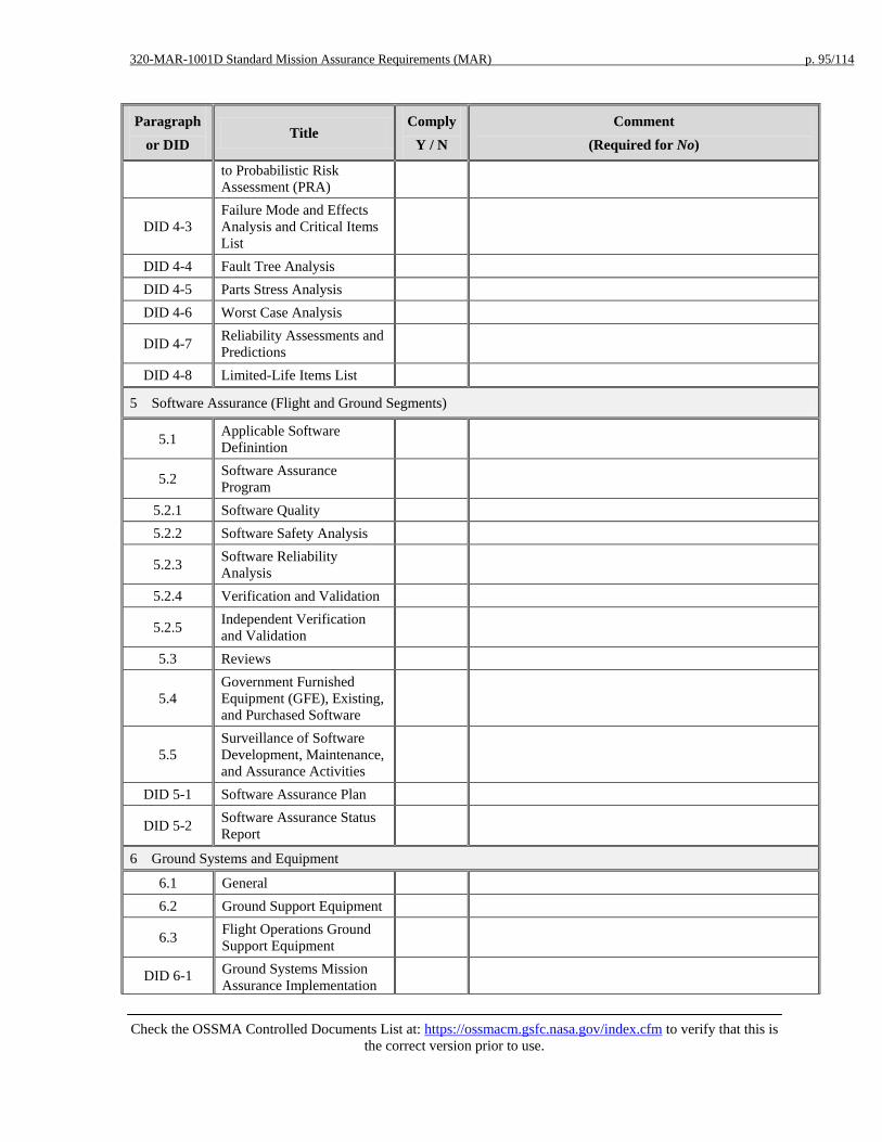
320-MAR-1001D Standard Mission Assurance Requirements (MAR) p. 95/114
Check the OSSMA Controlled Documents List at: https://ossmacm.gsfc.nasa.gov/index.cfm to verify that this is
the correct version prior to use.
Paragraph or DID
Title Comply
Y / N Comment
(Required for No)
to Probabilistic Risk Assessment (PRA)
DID 4-3 Failure Mode and Effects Analysis and Critical Items List
DID 4-4 Fault Tree Analysis DID 4-5 Parts Stress Analysis DID 4-6 Worst Case Analysis
DID 4-7 Reliability Assessments and Predictions
DID 4-8 Limited-Life Items List
5 Software Assurance (Flight and Ground Segments)
5.1 Applicable Software Definintion
5.2 Software Assurance Program
5.2.1 Software Quality 5.2.2 Software Safety Analysis
5.2.3 Software Reliability Analysis
5.2.4 Verification and Validation
5.2.5 Independent Verification and Validation
5.3 Reviews
5.4 Government Furnished Equipment (GFE), Existing, and Purchased Software
5.5 Surveillance of Software Development, Maintenance, and Assurance Activities
DID 5-1 Software Assurance Plan
DID 5-2 Software Assurance Status Report
6 Ground Systems and Equipment
6.1 General 6.2 Ground Support Equipment
6.3 Flight Operations Ground Support Equipment
DID 6-1 Ground Systems Mission Assurance Implementation

320-MAR-1001D Standard Mission Assurance Requirements (MAR) p. 96/114
Check the OSSMA Controlled Documents List at: https://ossmacm.gsfc.nasa.gov/index.cfm to verify that this is
the correct version prior to use.
Paragraph or DID
Title Comply
Y / N Comment
(Required for No)
Plan
DID 6-2 Ground Support Equipment Plan
DID 6-3 Ground Operations Equipment Plan
7 Risk Management
7.1 General 7.2 Risk List
DID 7-1 Risk Management Plan DID 7-2 Risk List
8 Systems Reviews
8.1 Systems Reviews 8.2 Peer Reviews
DID 8-1 Systems Review Materials DID 8-2 Action Item Responses
DID 8-3 Engineering Peer Review Program
9 System Performance Verification
9.1 System Performance Verification Program Plan
9.2 Environmental Verificaton Plan
9.3 System Performance Verification Matrix
9.4 Environmental Test Matrix 9.5 Verification Reports
9.6 System Performance Verification Report
DID 9-1 System Performance Verification Plan
DID 9-2 Environmental Verification Plan
DID 9-3 System Performance Verification Matrix
DID 9-4 Environmental Test Matrix DID 9-5 Verification Reports
DID 9-6 System Performance Verification Report
10 Workmanship

320-MAR-1001D Standard Mission Assurance Requirements (MAR) p. 97/114
Check the OSSMA Controlled Documents List at: https://ossmacm.gsfc.nasa.gov/index.cfm to verify that this is
the correct version prior to use.
Paragraph or DID
Title Comply
Y / N Comment
(Required for No)
10.1 General
10.2 Personnel Certification for J-STD-001ES
10.3 Design and Process Qualification
10.4 Electrostatic Discharge Control (ESD)
10.5 Splices, Circuit Board Trace Cuts, and Jumper Wires
DID 10-1 ESD Control Plan
11 EEE Parts
11.1 General 11.2 Parts Control Board 11.3 EEE Parts Lists
11.3.1 Parts Identification List (PIL)
11.3.2 Project Approved Parts List (PAPL)
11.3.3 As-Designed Parts List (ADPL)
11.3.4 As-Built Parts List (ABPL) DID 11-1 Parts Control Plan DID 11-2 Parts Control Board DID 11-3 Parts Identification List DID 11-4 Project Approved Parts List DID 11-5 As Designed Parts List DID 11-6 As Built Parts List
12 Materials and Processes
12.1 General
12.2 Life Test Plan for Lubricated Mechanisms
12.3 Materials Usage Agreement (MUL)
12.4 Materials Identification and Usage List (MIUL)
12.5 Nondestructive Evaluation Plan (NDE)
12.6 Printed Wiring Board Test Coupons

320-MAR-1001D Standard Mission Assurance Requirements (MAR) p. 98/114
Check the OSSMA Controlled Documents List at: https://ossmacm.gsfc.nasa.gov/index.cfm to verify that this is
the correct version prior to use.
Paragraph or DID
Title Comply
Y / N Comment
(Required for No)
12.7 Fire-Retardant Polyimide Laminate
12.8 Titanium Alloys
DID 12-1 Materials & Processes Selection, Control, and Implementation
DID 12-2 Life Test Plan for Lubricated Mechanisms
DID 12-3 Materials Usage Agreement
DID 12-4 Materials Identification and Usage List
DID 12-5 Nondestructive Evaluation Plan
DID 12-6 Printed Wiring Boards Test Coupons
DID 12-7 Fire-retardant Polyimide Laminate in PWBs
DID 12-8 Titanium Alloys
13 Contamination Control
13.1 Contamination Control Plan
DID 13-1 Contamination Control Plan and Data
14 Metrology and Calibration
14.1 Metrology and Calibration Program
14.2 Use of Non-calibrated Instruments
15 GIDEP Alerts and Problem Advisories
15.1 Government-Industry Data Exchange Program (GIDEP)
15.2 Alert Disposition
15.3 GIDEP Reporting
15.4 Review Reporting
DID 15-1 GIDEP Alert and NASA Advisory Dispositions
DID 15-2 Significant Parts, Materials, and Safety Problems
16 End Item Acceptance Data Package
16 End Item Acceptance Data

320-MAR-1001D Standard Mission Assurance Requirements (MAR) p. 99/114
Check the OSSMA Controlled Documents List at: https://ossmacm.gsfc.nasa.gov/index.cfm to verify that this is
the correct version prior to use.
Paragraph or DID
Title Comply
Y / N Comment
(Required for No)
Package
DID 16-1 End Item Acceptance Data Package
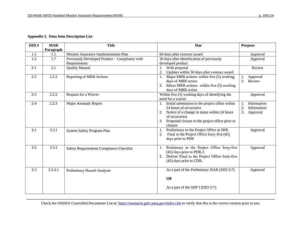
320-MAR-1001D Standard Mission Assurance Requirements (MAR) p. 100/114
Check the OSSMA Controlled Documents List at: https://ossmacm.gsfc.nasa.gov/index.cfm to verify that this is the correct version prior to use.
Appendix 5. Data Item Description List DID # MAR
Paragraph Title Due Purpose
1-1 1.1 Mission Assurance Implementation Plan 60 days after contract award Approval 1-2 1.7 Previously Developed Product – Compliance with
Requirements 30 days after identification of previously developed product
Approval
2-1 2.1 Quality Manual 1. With proposal 2. Updates within 30 days after contract award
Review
2-2 2.2.2 Reporting of MRB Actions 1. Major MRB actions: within five (5) working days of MRB action
2. Minor MRB actions: within five (5) working days of MRB action
1. Approval 2. Review
2-3 2.2.2 Request for a Waiver Within five (5) working days of identifying the need for a waiver
Approval
2-4 2.2.3 Major Anomaly Report 1. Initial submission to the project office within 24 hours of occurrence
2. Notice of a change in status within 24 hours of occurrence
3. Proposed closure to the project office prior to closure
1. Information 2. Information 3. Approval
3-1 3.3.1 System Safety Program Plan 1. Preliminary to the Project Office at SRR. 2. Final to the Project Office forty-five (45)
days prior to PDR
Approval
3-2 3.3.2 Safety Requirements Compliance Checklist 1. Prelminary to the Project Office forty-five (45) days prior to PDR.3
2. Deliver Final to the Project Office forty-five (45) days prior to CDR.
Approval
3-3 3.3.3.1 Preliminary Hazard Analysis As a part of the Preliminary ISAR (DID 3-7) OR As a part of the SDP I (DID 3-7)
Approval
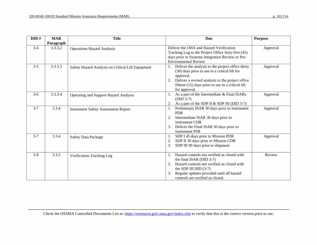
320-MAR-1001D Standard Mission Assurance Requirements (MAR) p. 101/114
Check the OSSMA Controlled Documents List at: https://ossmacm.gsfc.nasa.gov/index.cfm to verify that this is the correct version prior to use.
DID # MAR Paragraph
Title Due Purpose
3-4 3.3.3.2 Operations Hazard Analysis Deliver the OHA and Hazard Verification Tracking Log to the Project Office forty-five (45) days prior to Systems Integration Review or Pre-Environmental Review
Approval
3-5 3.3.3.3 Safety Hazard Analysis on Critical Lift Equipment 1. Deliver the analysis to the project office thirty (30) days prior to use in a critical lift for approval.
2. Deliver a revised analysis to the project office fifteen (15) days prior to use in a critical lift for approval.
Approval
3-6 3.3.3.4 Operating and Support Hazard Analysis 1. As a part of the Intermediate & Final ISARs (DID 3-7)
2. As a part of the SDP II & SDP III (DID 3-7)
Approval
3-7 3.3.4 Instrument Safety Assessment Report 1. Preliminary ISAR 30 days prior to instrument PDR
2. Intermediate ISAR 30 days prior to instrument CDR
3. Deliver the Final ISAR 30 days prior to instrument PSR
Approval
3-7 3.3.4 Safety Data Package 1. SDP I 45 days prior to Mission PDR 2. SDP II 30 days prior to Mission CDR 3. SDP III 90 days prior to shipment
Approval
3-8 3.3.5 Verification Tracking Log 1. Hazard controls not verified as closed with the final ISAR (DID 3-7)
2. Hazard controls not verified as closed with the SDP III DID (3-7)
3. Regular updates provided until all hazard controls are verified as closed.
Review

320-MAR-1001D Standard Mission Assurance Requirements (MAR) p. 102/114
Check the OSSMA Controlled Documents List at: https://ossmacm.gsfc.nasa.gov/index.cfm to verify that this is the correct version prior to use.
DID # MAR Paragraph
Title Due Purpose
3-9 3.3.6 Hazardous Procedures for Payload I&T and Pre-Launch Processing
1. I&T hazardous procedures to Project Office 7 days before first use
2. Launch Range Hazardous Procedures to the Project Office 60 days prior to first use
3. Launch Range Hazardous Procedures to Range Safety forty-five (45) days prior to first use (after NASA approval)
Approval
3-10 3.3.7 Safety Waivers Within thirty (30) days of identifying the need for a waiver
Approval
3-11 3.3.8 Input to Orbital Debris Assessment Report (ODAR) and End of Mission Plan (EOMP)
1. Deliver preliminary inputs to the Project Office fifteen (15) days prior to mission PDR.
2. Deliver interim inputs to the Project Office sixty (60) days prior to mission CDR.
3. Deliver the final/updated inputs to the Project Office 90 days prior to PSR.
Information
3-12 3.3.9 Pre-Mishap Plan 45 days prior to mission PDR Approval 3-13 3.3.10 Range Safety Forms 1. With Final ISAR (DID 3-7)
2. With SDP III (DID 3-7) Review
4-1 4.1 Reliability Program Plan 1. Sixty (60) days after contract award 2. Final plan 30 days prior to the Systems
Requirements Review 3. Activity reports at milestone reviews
beginning with the Systems Requirements Review
1. Review 2. Approval 3. Review

320-MAR-1001D Standard Mission Assurance Requirements (MAR) p. 103/114
Check the OSSMA Controlled Documents List at: https://ossmacm.gsfc.nasa.gov/index.cfm to verify that this is the correct version prior to use.
DID # MAR Paragraph
Title Due Purpose
4-2* 4.2 Probabilistic Risk Assessment 1. Deliver a PRA plan to the Project office sixty (60) days after contract award
2. Deliver interim PRA to the Project Office thirty (30) days prior to PDR.
3. Deliver updated interim PRA to the Project Office thirty (30) days prior to CDR.
4. Deliver updated interim PRA to the Project Office thirty (30) days prior to MOR.
5. Deliver final PRA to the Project Office thirty (30) days prior to FOR.
1. Review 2. Review 3. Review 4. Review 5. Approval
4-2 4-2 Input to the Probalistic Risk assessment (PRA) 1. Deliver preliminary heritage information, including the percent applicable, to the Project Office sixty (60) days after contract award.
2. Deliver updated heritage information, including the percent applicable heritage to the subject mission, to the Project Office thirty (30) days to prior major milestone reviews beginning with the SRR.
3. Deliver product information and process information for elements within the scope of the Mission PRA to the Project Office thirty (90) days prior to the PDR and thirty (30) days prior to subsequent major milestone reviews.
Information
4-3 4.3 Failure Mode and Effects Analysis and Critical Items List 1. Preliminary FMEA thirty (30) days before PDR
2. Final FMEA thirty (30) days prior to CDR 3. Updated FMEA and CIL thirty (30) days prior
to each subsequent milestone review leading up to Launch
1. Review 2. Approval 3. Approval

320-MAR-1001D Standard Mission Assurance Requirements (MAR) p. 104/114
Check the OSSMA Controlled Documents List at: https://ossmacm.gsfc.nasa.gov/index.cfm to verify that this is the correct version prior to use.
DID # MAR Paragraph
Title Due Purpose
4-4 4.4 Fault Tree Analysis 1. Preliminary qualitative FTA report thirty (30) days prior to PDR
2. Final qualitative FTA report thirty (30) days prior to CDR
3. Updated qualitative FTA report thirty (30) days of updates/changes
4. Final quantitative FTA report in support of pivotal event analysis as part of each PRA report
1. Review 2. Approval 3. Approval 4. Approval
4-5 4.5 Parts Stress Analysis 1. Forty-five (45) days prior to CDR 2. Revisions within thirty (30) days
Review
4-6 4.6 Worst Case Analysis 1. Thirty (30) days prior to CDR 2. Revisions within thirty (30) days
Review
4-7 4.7 Reliability Assessments and Predictions 1. Methodology thirty (30) days prior to System Requirements Review
2. Initial report thirty (30) days prior to PDR 3. Final report thirty (30) days prior to CDR
Review
4-8 4.10 Limited-Life Items List 1. Thirty (30) days prior to PDR 2. Updates to the Project Office within thirty
(30) days of changes
Approval
5-1 5.2 Software Assurance Plan 1. Preliminary plan to the Project Office thirty (30) days prior to SRR
2. Baseline plan to the Project Office fifteen (15) days prior to PDR
3. Updates to the Project Office fifteen (15) days prior to implementation
1. Review 2. Approval 3. Approval
5-2 5.5 Software Assurance Status Report 1. Monthly beginning sixty (60) days after contract award
Information
6-1 6.1 Ground Systems Mission Assurance Implementation Plan Thirty (30) days after contract award Approval 6-2 6.2 Ground Support Equipment Plan Thirty (30) days prior to System Requirements
Review Approval
6-3 6.3 Ground Operations Equipment Plan 1. Fifteen (15) days prior to mission PDR 2. Fifteen (15) days prior to mission CDR
1. Review 2. Approval
7-1 7.1 Risk Management Plan Sixty (60) days after contract award Approval

320-MAR-1001D Standard Mission Assurance Requirements (MAR) p. 105/114
Check the OSSMA Controlled Documents List at: https://ossmacm.gsfc.nasa.gov/index.cfm to verify that this is the correct version prior to use.
DID # MAR Paragraph
Title Due Purpose
7-2 7.2 Risk List Monthly beginning with PDR Review 8-1 8.1 Systems Review Materials 1. Agenda fourteen (14) days prior to
commencement of the review 2. Presentation materials seven (7) days prior to
the review 3. Reference materials at the review
Information
8-2 8.1 Action Item Responses Thirty (30) days after end of review Approval 8-3 8.2 Peer Review Program Sixty (60) days after contract award Review 9-1 9.1 System Performance Verification Plan 1. Preliminary plan thirty (30) days prior to PDR
2. Final plan thirty (30) days prior to CDR 1. Review 2. Approval
9-2 9.2 Environmental Verification Plan 1. Preliminary plan thirty (30) days prior to PDR 2. Final plan thirty (30) days prior to CDR
1. Review 2. Approval
9-3 9.3 System Performance Verification Matrix Updated matrix included in the data packages for the Integrated Independent Reviews beginning with PDR
Review
9-4 9.4 Environmental Test Matrix Updated matrix included in the review data package for milestone reviews beginning with PDR.
Review
9-5 9.5 Verification Reports 1. Preliminary verification report within seventy-two (72) hours of test completion
2. Final verification report within thirty (30) days of test completion
Information
9-6 9.6 System Performance Verification Report 1. Updated reports with the review data package at milestone reviews, beginning with CDR
2. Final report within thirty (30) days after completion of on-orbit checkout
Information
10-1 10.3 ESD Control Plan Thirty (30) days prior to PDR Review 11-1 11.1 Parts Control Plan Thirty (30) days after contract award Approval 11-2 11.2 Parts Control Board Thirty (30) days after contract award Approval 11-3 11.3.1 Parts Identification List Ten (10) business days prior to the PCB meeting Approval 11-4 11.3.2 Project approved Parts List Ten (10) business days prior to the PCB meeting
at which they will be presented Approval
11-5 11.3.3 As designed Parts List Ten (10) business days prior to the PCB meeting at which they will be presented
Approval

320-MAR-1001D Standard Mission Assurance Requirements (MAR) p. 106/114
Check the OSSMA Controlled Documents List at: https://ossmacm.gsfc.nasa.gov/index.cfm to verify that this is the correct version prior to use.
DID # MAR Paragraph
Title Due Purpose
11-6 11.3.4 As Built Parts List Ten (10) business days prior to the PCB meeting at which they will be reviewed
Review
12-1 12.1 Materials & Processes Selection, Control, and Implementation Plan
Sixty (60) days after contract award Approval
12-2 12.2 Life Test Plan for Lubricated Mechanisms 1. Plan thirty (30) days prior to PDR 2. Report thirty (30) days after acceptance test
completion
1. Approval 2. Review
12-3 12.3 Materials Usage Agreement 1. New MUAs thirty (30) days prior to CDR 2. Revised MUAs within thirty (30) days of
identification
1. Approval 2. Approval
12-4 12.4 Materials Identification and Usage List 1. Thirty (30) days prior to PDR 2. Thirty (30) days prior to CDR 3. Updates to the Project Office within thirty
(30) days of identification
1. Review 2. Approval 3. Review
12-5 12.5 Nondestructive Evaluation Plan 1. Thirty (30) days prior to PDR 2. Thirty (30) days prior to CDR 3. Updates thirty (30) days after identification
1. Review 2. Approval 3. Approval
12-6 12.6 Printed Wiring Boards Test Coupons As soon as practicable Approval 13-1 13.1 Contamination Control Plan 1. Plan thirty (30) days before PDR
2. Plan thirty (30) days before the CDR 3. Final thermal vacuum bakeout results
provided within thirty (30) of completion 4. Contamination certificate of compliance with
End Item Acceptance Data Package
1. Review 2. Approval 3. Review 4. Review
15-1 15.4 GIDEP Alert and NASA Advisory Dispositions 1. Alert disposition within thirty (30) days of identification of potential use or use of a EEE part or material
2. Disposition of Alerts provided by the Project Office within thirty (30) days
Review
15-2 15.4 Significant Parts, Materials, and Safety Problems Within thirty (30) days Review 16-1 16 End Item Acceptance Data Package Thirty (30) days prior to end item delivery Approval
* Delete one of the two per the related tailoring in the narrative
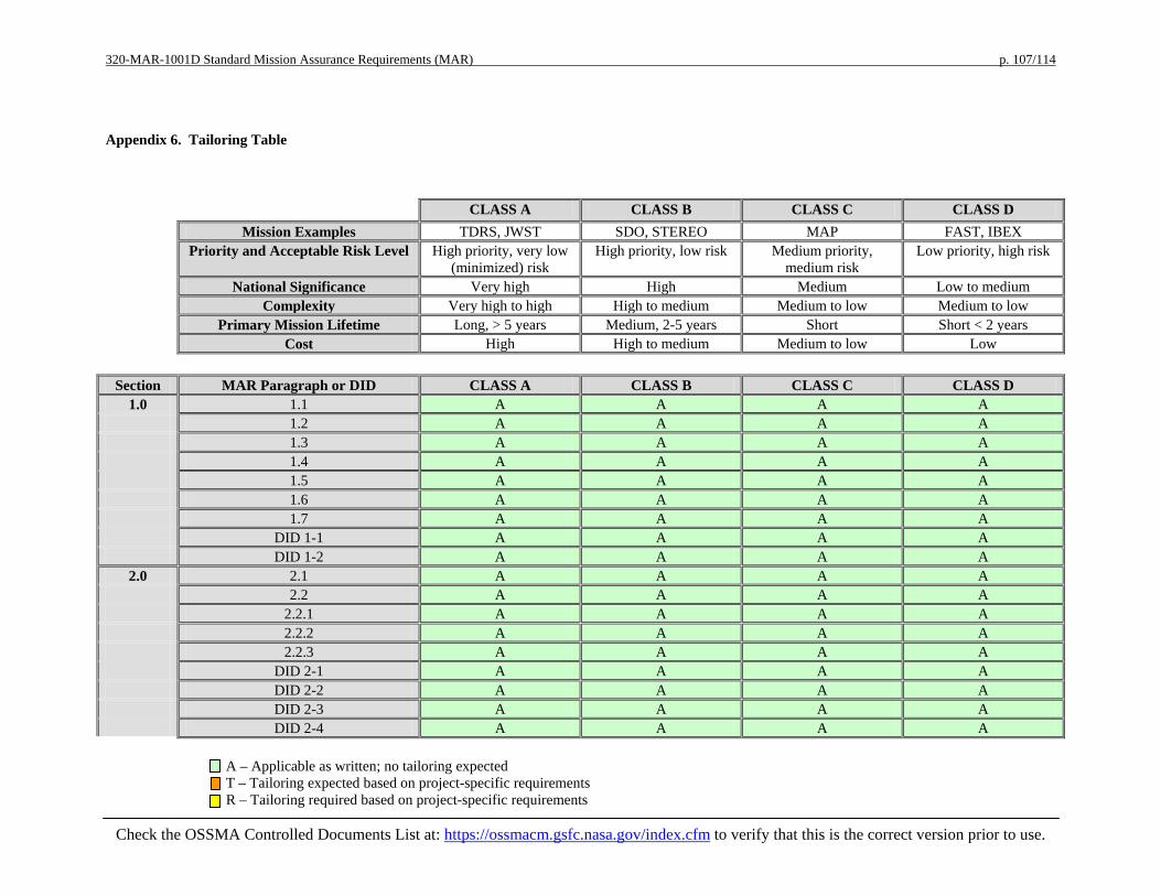
320-MAR-1001D Standard Mission Assurance Requirements (MAR) p. 107/114
A – Applicable as written; no tailoring expected T – Tailoring expected based on project-specific requirements R – Tailoring required based on project-specific requirements
Check the OSSMA Controlled Documents List at: https://ossmacm.gsfc.nasa.gov/index.cfm to verify that this is the correct version prior to use.
Appendix 6. Tailoring Table
CLASS A CLASS B CLASS C CLASS D Mission Examples TDRS, JWST SDO, STEREO MAP FAST, IBEX Priority and Acceptable Risk Level High priority, very low
(minimized) risk High priority, low risk Medium priority,
medium risk Low priority, high risk
National Significance Very high High Medium Low to medium Complexity Very high to high High to medium Medium to low Medium to low Primary Mission Lifetime Long, > 5 years Medium, 2-5 years Short Short < 2 years Cost High High to medium Medium to low Low
Section MAR Paragraph or DID CLASS A CLASS B CLASS C CLASS D
1.0 1.1 A A A A 1.2 A A A A 1.3 A A A A 1.4 A A A A 1.5 A A A A 1.6 A A A A 1.7 A A A A DID 1-1 A A A A DID 1-2 A A A A
2.0 2.1 A A A A 2.2 A A A A 2.2.1 A A A A 2.2.2 A A A A 2.2.3 A A A A DID 2-1 A A A A DID 2-2 A A A A DID 2-3 A A A A DID 2-4 A A A A
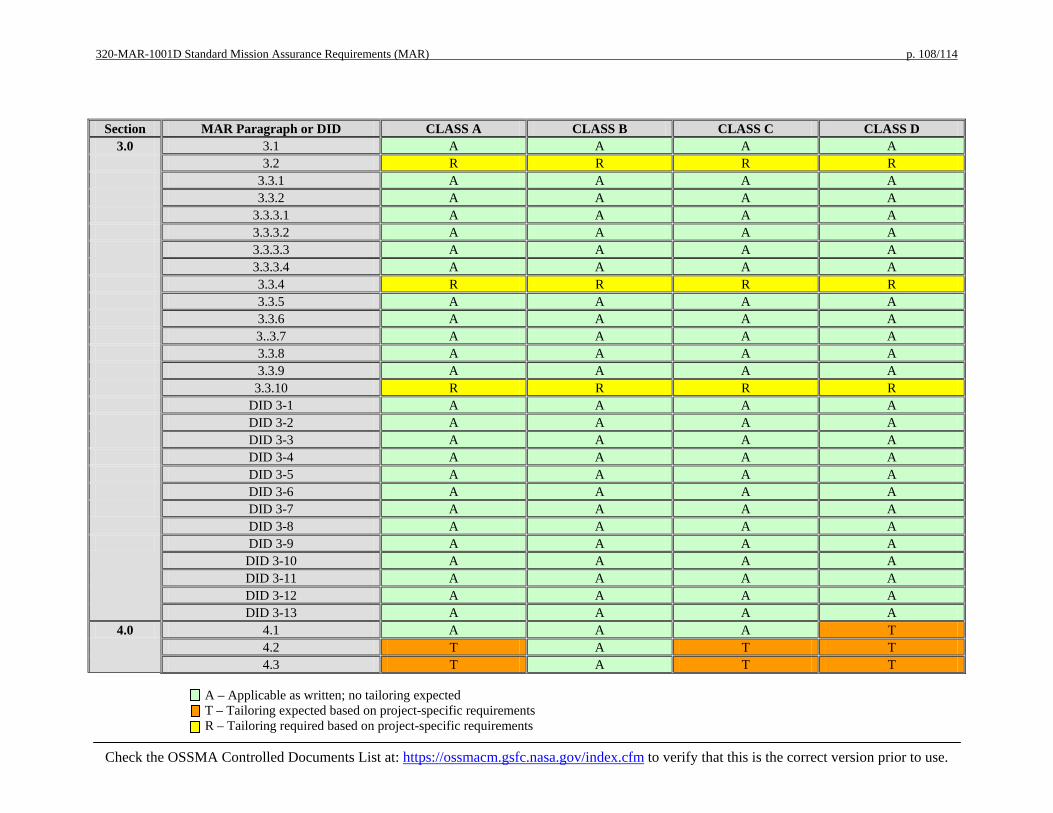
320-MAR-1001D Standard Mission Assurance Requirements (MAR) p. 108/114
A – Applicable as written; no tailoring expected T – Tailoring expected based on project-specific requirements R – Tailoring required based on project-specific requirements
Check the OSSMA Controlled Documents List at: https://ossmacm.gsfc.nasa.gov/index.cfm to verify that this is the correct version prior to use.
Section MAR Paragraph or DID CLASS A CLASS B CLASS C CLASS D 3.0 3.1 A A A A
3.2 R R R R 3.3.1 A A A A 3.3.2 A A A A 3.3.3.1 A A A A 3.3.3.2 A A A A 3.3.3.3 A A A A 3.3.3.4 A A A A 3.3.4 R R R R 3.3.5 A A A A 3.3.6 A A A A 3..3.7 A A A A 3.3.8 A A A A 3.3.9 A A A A 3.3.10 R R R R DID 3-1 A A A A DID 3-2 A A A A DID 3-3 A A A A DID 3-4 A A A A DID 3-5 A A A A DID 3-6 A A A A DID 3-7 A A A A
DID 3-8 A A A A DID 3-9 A A A A
DID 3-10 A A A A DID 3-11 A A A A DID 3-12 A A A A DID 3-13 A A A A
4.0 4.1 A A A T 4.2 T A T T 4.3 T A T T

320-MAR-1001D Standard Mission Assurance Requirements (MAR) p. 109/114
A – Applicable as written; no tailoring expected T – Tailoring expected based on project-specific requirements R – Tailoring required based on project-specific requirements
Check the OSSMA Controlled Documents List at: https://ossmacm.gsfc.nasa.gov/index.cfm to verify that this is the correct version prior to use.
Section MAR Paragraph or DID CLASS A CLASS B CLASS C CLASS D 4.4 A A A T 4.5 A A A T 4.6 A A T T 4.7 A A T T 4.8 A A A T 4.9 A A A T
4.10 A A A T DID 4-1 A A A A DID 4-2 T A T T DID 4-3 T A T T DID 4-4 A A A T DID 4-5 A A A T DID 4-6 A A T T DID 4-7 A A T T DID 4-8 A A A T
5.0 5.1 A A A A 5.2 A A A A 5.2.1 A A A A 5.2.2 A A A A 5.2.3 A A A A
5.2.4 A A A A 5.2.5 A A A A 5.3 A A A A 5.4 A A A A
5.5 A A A A DID 5-1 A A A A DID 5-2 A A A A
6.0 6.1 A A A A 6.2 A A A A
6.3 A A A A DID 6-1 A A A A

320-MAR-1001D Standard Mission Assurance Requirements (MAR) p. 110/114
A – Applicable as written; no tailoring expected T – Tailoring expected based on project-specific requirements R – Tailoring required based on project-specific requirements
Check the OSSMA Controlled Documents List at: https://ossmacm.gsfc.nasa.gov/index.cfm to verify that this is the correct version prior to use.
Section MAR Paragraph or DID CLASS A CLASS B CLASS C CLASS D DID 6-2 A A A A
DID 6-3 A A A A 7.0 7.1 A A A A
7.2 A A A A DID 7-1 A A A A DID 7-2 A A A A
8.0 8.1 A A A A 8.2 A A A A
DID 8-1 A A A A DID 8-2 A A A A DID 8-3 A A A A
9.0 9.1 A A A A 9.2 A A A A 9.3 A A A A 9.4 A A A A 9.5 A A A A
9.6 A A A A DID 9-1 A A A A DID 9-2 A A A A DID 9-3 A A A A DID 9-4 A A A A
DID 9-5 A A A A DID 9-6 A A A A
10.0 10.1 A A A A 10.2 A A A A
10.3 A A A A 10.4 A A A A DID 10-1 A A A A
11.0 11.1 T A T T 11.2 A A A A 11.3 A A A A

320-MAR-1001D Standard Mission Assurance Requirements (MAR) p. 111/114
A – Applicable as written; no tailoring expected T – Tailoring expected based on project-specific requirements R – Tailoring required based on project-specific requirements
Check the OSSMA Controlled Documents List at: https://ossmacm.gsfc.nasa.gov/index.cfm to verify that this is the correct version prior to use.
Section MAR Paragraph or DID CLASS A CLASS B CLASS C CLASS D 11.3.1 A A T T 11.3.2 A A A A
11.3.3 A A A A 11.3.4 A A A A
DID 11-1 T A T T DID 11-2 A A A A DID 11-3 A A A T
DID 11-4 A A A A DID 11-5 A A A A DID 11-6 A A A A
12.0 12.1 A A A A 12.2 A A A A
12.3 A A A A 12.4 A A A A 12.5 A A A A 12.6 A A A A
12.7 A A A A 12.8 A A A A
DID 12-1 R R R R DID 12-2 A A A A
DID 12-3 A A A T DID 12-4 A A A T DID 12-5 A A A T DID 12-6 A A A A
13.0 13.1 A A A A DID 13-1 A A A A
14.0 14.1 A A A A 14.2 A A A A
15.0
15.1 A A A A 15.2 A A A A 15.3 A A A A
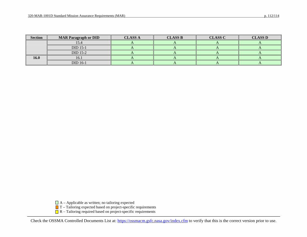
320-MAR-1001D Standard Mission Assurance Requirements (MAR) p. 112/114
A – Applicable as written; no tailoring expected T – Tailoring expected based on project-specific requirements R – Tailoring required based on project-specific requirements
Check the OSSMA Controlled Documents List at: https://ossmacm.gsfc.nasa.gov/index.cfm to verify that this is the correct version prior to use.
Section MAR Paragraph or DID CLASS A CLASS B CLASS C CLASS D 15.4 A A A A
DID 15-1 A A A A DID 15-2 A A A A
16.0 16.1 A A A A DID 16-1 A A A A

320-MAR-1001D Standard Mission Assurance Requirements (MAR) p. 113/114
Check the OSSMA Controlled Documents List at: https://ossmacm.gsfc.nasa.gov/index.cfm to verify
that this is the correct version prior to use.
CHANGE HISTORY LOG
Revision Effective Date Description of Changes
- 08/10/09 Baseline Issue – CCR-D-0007
A 11/13/09
Revision A Approved per CCR-D-0017 • See CCR # for complete list of changes • Significant changes in Section 4 of Appendices 1 and 3 • Added notes in various places to enhance clarity • Modified due dates for several DIDs to better align with
project schedules • Added language to Section 3.1 to describe the use of
Appendix 4 MAR Response Form • Added Appendix 4 and renumbered subsequent appendix
B 05/20/2010
Revision B Approved per CCR-D-0022 • 10.4 - Added to prohibit jumper wires and trace cuts on circuit
boards • 12.7 - Added Control Level 2C to indicate the exact restriction
on lead-free finishes • 12.8 - Added to prohibit the use of fire retardant laminate in
flight circuit boards • DID 6-2 - Revised to require single fault tolerance at flight
equipment interfaces and FMEA for the flight equipment interfaces
• DID 11-1 – Added requirement for a counterfeit parts control plan per AS5553
• Revised related areas in the document to reflect the above changes
C 03/14/2011
Revision C Approved per CCR-D-0032 • Sect. 3: added 321-REQ-1001 regarding processing of Li-ion
batteries • Revised ordering of hazard analyses • Added EOMP to ODAR • Revised mishap reporting phrasing Sect. 4 • Changes regarding PRA; changes in depth of various analyses • Sect. 5: complete rewrite • Sect. 10: specified revision B of IPC-6012; modified wording
regarding trace cuts and jumpers, added splices • Sect. 12: modified Pb-free and Sn whisker control wording;
modified fire retardant polyimide wording • Revised acronyms as necessary • Reworked DIDs and other sections to reconcile changes
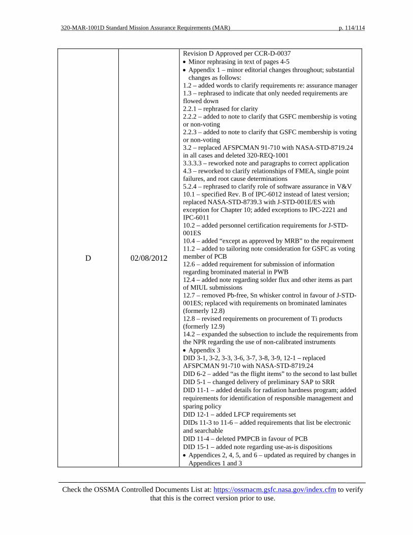
320-MAR-1001D Standard Mission Assurance Requirements (MAR) p. 114/114
Check the OSSMA Controlled Documents List at: https://ossmacm.gsfc.nasa.gov/index.cfm to verify
that this is the correct version prior to use.
D 02/08/2012
Revision D Approved per CCR-D-0037 • Minor rephrasing in text of pages 4-5 • Appendix 1 – minor editorial changes throughout; substantial
changes as follows: 1.2 – added words to clarify requirements re: assurance manager 1.3 – rephrased to indicate that only needed requirements are flowed down 2.2.1 – rephrased for clarity 2.2.2 – added to note to clarify that GSFC membership is voting or non-voting 2.2.3 – added to note to clarify that GSFC membership is voting or non-voting 3.2 – replaced AFSPCMAN 91-710 with NASA-STD-8719.24 in all cases and deleted 320-REQ-1001 3.3.3.3 – reworked note and paragraphs to correct application 4.3 – reworked to clarify relationships of FMEA, single point failures, and root cause determinations 5.2.4 – rephrased to clarify role of software assurance in V&V 10.1 – specified Rev. B of IPC-6012 instead of latest version; replaced NASA-STD-8739.3 with J-STD-001E/ES with exception for Chapter 10; added exceptions to IPC-2221 and IPC-6011 10.2 – added personnel certification requirements for J-STD-001ES 10.4 – added “except as approved by MRB” to the requirement 11.2 – added to tailoring note consideration for GSFC as voting member of PCB 12.6 – added requirement for submission of information regarding brominated material in PWB 12.4 – added note regarding solder flux and other items as part of MIUL submissions 12.7 – removed Pb-free, Sn whisker control in favour of J-STD-001ES; replaced with requirements on brominated laminates (formerly 12.8) 12.8 – revised requirements on procurement of Ti products (formerly 12.9) 14.2 – expanded the subsection to include the requirements from the NPR regarding the use of non-calibrated instruments • Appendix 3 DID 3-1, 3-2, 3-3, 3-6, 3-7, 3-8, 3-9, 12-1 – replaced AFSPCMAN 91-710 with NASA-STD-8719.24 DID 6-2 – added “as the flight items” to the second to last bullet DID 5-1 – changed delivery of preliminary SAP to SRR DID 11-1 – added details for radiation hardness program; added requirements for identification of responsible management and sparing policy DID 12-1 – added LFCP requirements set DIDs 11-3 to 11-6 – added requirements that list be electronic and searchable DID 11-4 – deleted PMPCB in favour of PCB DID 15-1 – added note regarding use-as-is dispositions • Appendices 2, 4, 5, and 6 – updated as required by changes in
Appendices 1 and 3