standing seam installation guide - vmzinc tones of quartz-zinc blend well with existing construction...
TRANSCRIPT
Standing seaminstallation guide
Uniclass
CI/SfB(47)
G312:G24:P45:N131
January 2016Mh7
ROOFING
2 Standing seam installation guide
Contents
3 ......... Introduction to VMZINC
4 ......... Surface finishes
5 ......... Warm and cold roof build-ups
6 ......... Wall build-up
7 ......... Standing seam requirements
9 ......... Compatibility with other materials
10 ....... Detailing10. Eaves14. Hips18. Ridges22. Verges25. Transverse junctions28. Valleys30. Fascias32. Rooflights37. Windows
42 ....... Installing zinc
45 ....... Maintenance and storage
47 ....... Sustainable performance
VMZINC® manufactures a wide range ofrolled zinc products for use in constructionand has almost two centuries ofexperience. In addition to the standingseam system, products include rainwatersystems, cladding systems and decorativeroofing products such as dormers, bull’seyes, weather vanes, finials andbalustrades. VMZINC is part of the UmicoreGroup which has worldwide interests inprecious metal services, recycling of non-ferrous metals, and catalyst technologiesfor the automotive industry. It alsomanufactures substrates for photovoltaicsand LEDs, materials for photonics andlenses, and optical assemblies for nightvision applications.
Company profileand
background to zinc
Zinc is among the most sustainable metals used in constructiontoday and has been used on the roofs of Paris for almost 200years. VMZINC roof, wall and rainwater systems are also highlycost-effective, both from an initial procurement and design lifeperspective. Whether for new build or refurbishment, the VMZINCsystems have been designed to complement a wide range ofbuilding materials and styles.
The finishes available offer exceptional colour stability. Thisensures that maintenance requirements will be minimalthroughout the system’s design life and that the material’sinstalled appearance will be retained for many years.
VMZINC can be used for warm or cold roof constructions as well asrainscreen facades. Some of its many benefits are listed opposite.
3Standing seam installation guide
Introduction to VMZINC
Benefits of the VMZINC
systems
This installation guide is designed to givecontractors information about the use anddetailing of VMZINC, clarifying the limits ofthe material with specific regard to correctdetailing. This guide should be read andused in conjunction with other VMZINCdocuments including:VMZINC General Technical Recommendations
VMZINC Standing Seam Guidelines for Design & Specification
VMZINC Soldering
VMZ Standing Seam G3 Installation Guide
VMZINC Facades Guidelines for Design & Specification
VMZ Rainwater Systems Guidelines for Design & Installation
These documents address substrate requirements, compatibility with otherproducts and material aesthetics as well as many other subjects.
� Lightweight and durable
� Minimal expansion and creak
� Fully recyclable
� A design life of 80 years
� Virtually maintenance-free
� Can be installed on pitches from 3°-90°
� Complex shapes can be easily achieved.Zinc panels can be pre-curved to aradius as low as 600mm
� Can be used to cover soffits (box gutteroverhangs, etc)
� BRE Green Guide certified
� BBA certified
� Conforms to EN 988
� Can be laid in lengths up to 13 metreswithout the need for expansion steps
� Fire performance rating ‘AA’ - BS 476: Part 3(‘low vulnerability’ class in Scotland)
� VMZINC has a fire classification of A2-s1, d0in accordance with EN 13501-1 2002
� Available in a choice of natural finish, 6pre-weathered finishes, and anengraved finish
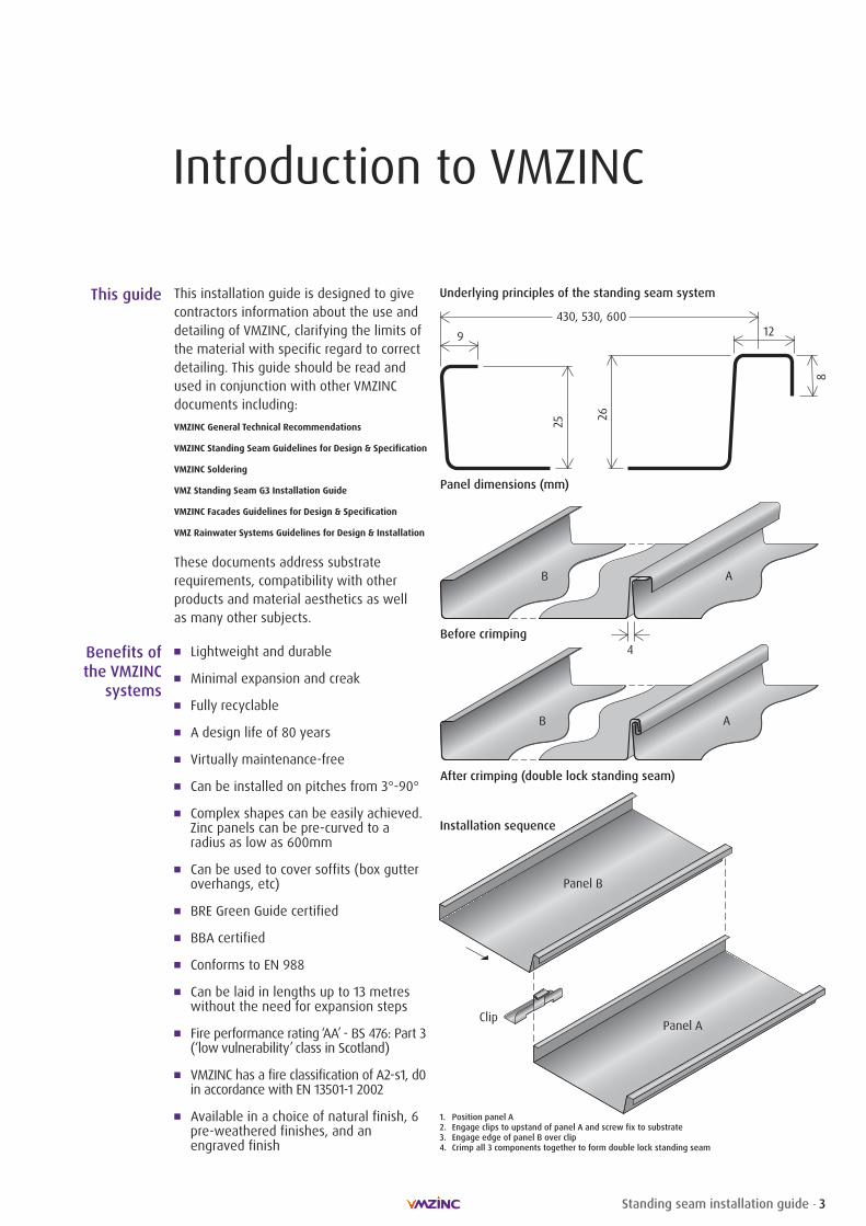
This guide
Before crimping
Panel dimensions (mm)
After crimping (double lock standing seam)
4
129
430, 530, 600
8
25 26
B A
B A
Panel B
Panel AClip
Installation sequence
1. Position panel A2. Engage clips to upstand of panel A and screw fix to substrate3. Engage edge of panel B over clip4. Crimp all 3 components together to form double lock standing seam
Underlying principles of the standing seam system
4 Standing seam installation guide
Surface finishes
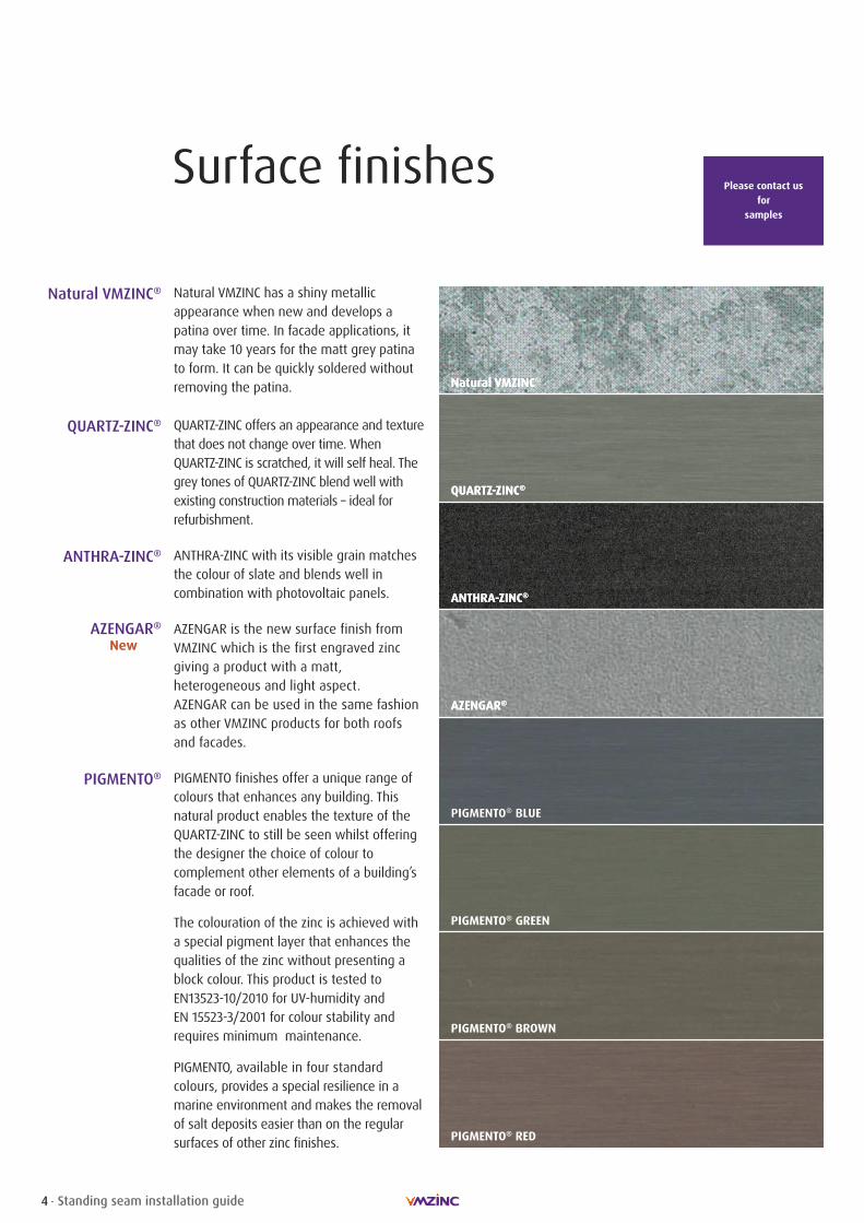
Natural VMZINCNatural VMZINC®
QUARTZ-ZINC®
ANTHRA-ZINC®
AZENGAR®AZENGAR®
QUARTZ-ZINC®
ANTHRA-ZINC®
PIGMENTO® BLUEPIGMENTO® BLUE
PIGMENTO® GREEN
PIGMENTO® BROWN
PIGMENTO® RED
Natural VMZINC®
QUARTZ-ZINC®
ANTHRA-ZINC®
Natural VMZINC has a shiny metallicappearance when new and develops apatina over time. In facade applications, itmay take 10 years for the matt grey patinato form. It can be quickly soldered withoutremoving the patina.
QUARTZ-ZINC offers an appearance and texturethat does not change over time. WhenQUARTZ-ZINC is scratched, it will self heal. Thegrey tones of QUARTZ-ZINC blend well withexisting construction materials – ideal forrefurbishment.
ANTHRA-ZINC with its visible grain matchesthe colour of slate and blends well incombination with photovoltaic panels.
AZENGAR®New
AZENGAR is the new surface finish fromVMZINC which is the first engraved zincgiving a product with a matt, heterogeneous and light aspect. AZENGAR can be used in the same fashionas other VMZINC products for both roofsand facades.
PIGMENTO finishes offer a unique range ofcolours that enhances any building. Thisnatural product enables the texture of theQUARTZ-ZINC to still be seen whilst offeringthe designer the choice of colour tocomplement other elements of a building’sfacade or roof.
The colouration of the zinc is achieved witha special pigment layer that enhances thequalities of the zinc without presenting ablock colour. This product is tested toEN13523-10/2010 for UV-humidity and EN 15523-3/2001 for colour stability andrequires minimum maintenance.
PIGMENTO, available in four standardcolours, provides a special resilience in amarine environment and makes the removalof salt deposits easier than on the regularsurfaces of other zinc finishes.
PIGMENTO®
Please contact us for
samples

5Standing seam installation guide
Warm and cold roof build-ups
Warm non-ventilated and cold ventilated roofs are two terms whichdo not always denote the same ideas to all building professionals. In order to put the warm non-ventilated roof system into context,we will refer to it as a roof where there is absolutely no ventedspace within the roof build-up and furthermore the entire roofstructure is on the warm side of the insulation. In the UK this meansthat the roof structure is entirely below the insulation.
Fundamental elements of the system:
� VMZINC PLUS must be used on all warm roof build-ups
� VMZINC Membrane must be used (breather membrane)
� The substrate must be continuous and even and the correctfixing clips must be used
� A fully supported continuous vapour barrier must be installed(bitumen-backed aluminium foil). Polythene films are notacceptable
� For humidity class 5 (swimming pools) the Compact roof withFoamglas must be used. This build-up, as with the Structuralroof, carries a BBA certificate
CERTIFICATE No 12/4900
Definition ofwarm roof in the UK
Basic requirements
VMZINC must not only be installed according to our recommendationsbut also designed to them as well. VMZINC can be installed on non-vented warm roof build-ups as well as on vented cold roof build-ups. For standing seam build-ups a roof would have a slope ofno more than 70º (Compact roof 60º); above this slope it should beconsidered wall cladding. All wall cladding should be ventilated.VMZINC will only give a warranty for recommended build-ups anddetails. The minimum slope for zinc roofs is 3º as built.
Definition ofcold roof in the UK
In order to put the cold ventilated roof system into context, wewill refer to it as a roof where there is a continuous air space of atleast 50mm between the substrate supporting the zinc and theinsulation. This air space must be a vented space with openingsgenerally at the eaves and the ridge.
Hybrid roofs are not recommended by VMZINC and can result in thewhole roof including the zinc failing.
Fundamental elements of the system:
� VMZINC PLUS must be used on plywood whereas VMZINC isacceptable on open-gap softwood boards
� VMZINC Membrane can be used to protect the insulation
� The substrate must be continuous and even, and the correctfixing clips must be used
Linear air vents must be at least 10mm wide and are commonlyprotected by insect mesh. It is always good practice to include avapour control layer in the build-up and this should be installedon the warm side of the insulation. The system is covered by theCode of Practice 143-5: 1964.
Result of using a hybrid roof.
Cold Roof: Air inlets and outlets are generally linear (at least 10mm wide) but can be individual. The ventilation must correspond to BS 5250: 2002.
Warm Roof: Continuous layer of insulation covering afully supported vapour barrier.
For further information please see ourbrochures on facades and the
standing seam system
Wall build-up
6 Standing seam installation guide
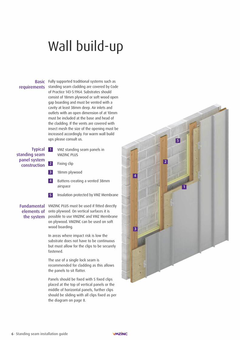
Typicalstanding seampanel systemconstruction
1
2
3
4
VMZ standing seam panels in VMZINC PLUS
Fixing clip
18mm plywood
Battens creating a vented 38mmairspace
Insulation protected by VMZ Membrane5
1
2
3
4
5
Basic requirements
Fully supported traditional systems such asstanding seam cladding are covered by Codeof Practice 143-5:1964. Substrates shouldconsist of 18mm plywood or soft wood opengap boarding and must be vented with acavity at least 38mm deep. Air inlets andoutlets with an open dimension of at 10mmmust be included at the base and head ofthe cladding. If the vents are covered withinsect mesh the size of the opening must beincreased accordingly. For warm wall buildups please consult us.
Fundamentalelements ofthe system
VMZINC PLUS must be used if fitted directlyonto plywood. On vertical surfaces it ispossible to use VMZINC and VMZ Membraneon plywood. VMZINC can be used on softwood boarding.
In areas where impact risk is low thesubstrate does not have to be continuousbut must allow for the clips to be securelyfastened.
The use of a single lock seam isrecommended for cladding as this allowsthe panels to sit flatter.
Panels should be fixed with 5 fixed clipsplaced at the top of vertical panels or themiddle of horizontal panels, further clipsshould be sliding with all clips fixed as perthe diagram on page 8.
Standing seam requirements
7Standing seam installation guide
Minimum slope
Panel size
Noise
VMZINC andVMZINC PLUS
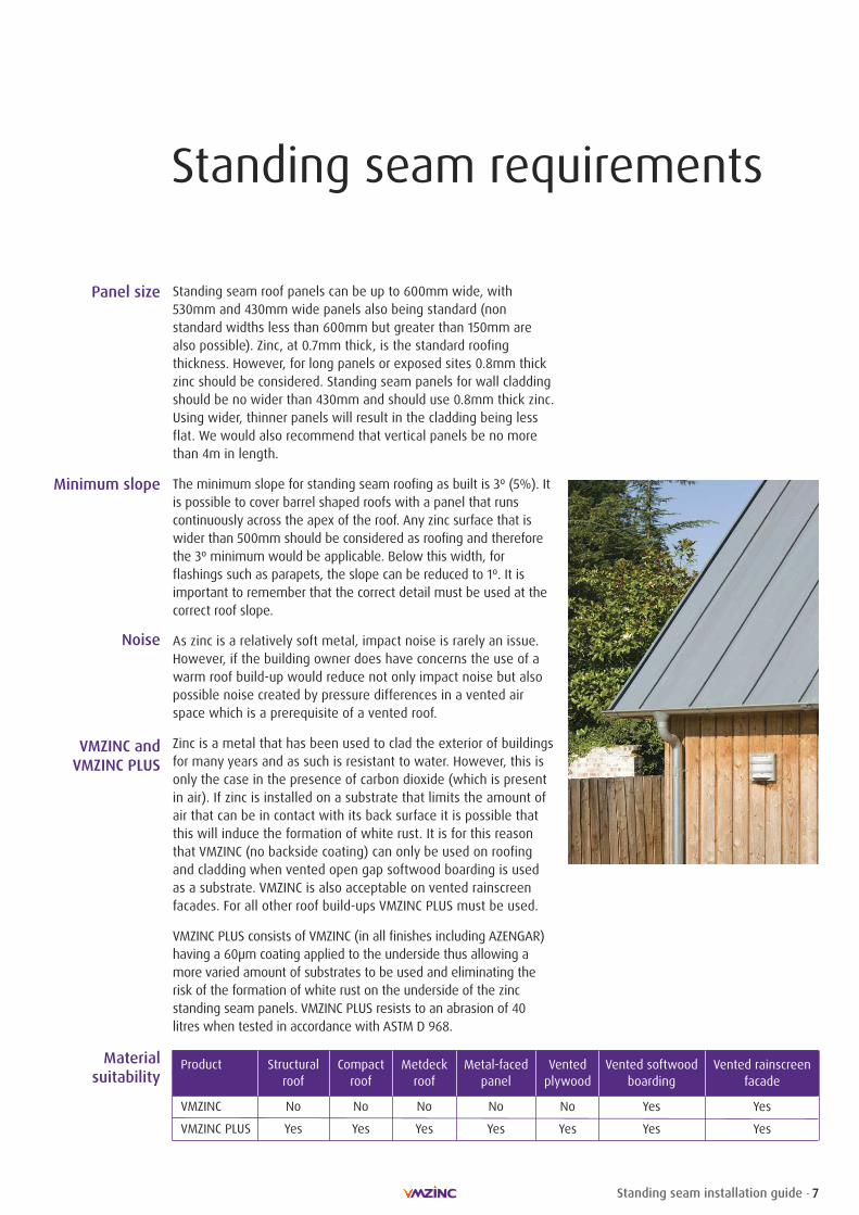
Standing seam roof panels can be up to 600mm wide, with530mm and 430mm wide panels also being standard (nonstandard widths less than 600mm but greater than 150mm arealso possible). Zinc, at 0.7mm thick, is the standard roofingthickness. However, for long panels or exposed sites 0.8mm thickzinc should be considered. Standing seam panels for wall claddingshould be no wider than 430mm and should use 0.8mm thick zinc.Using wider, thinner panels will result in the cladding being lessflat. We would also recommend that vertical panels be no morethan 4m in length.
The minimum slope for standing seam roofing as built is 3º (5%). Itis possible to cover barrel shaped roofs with a panel that runscontinuously across the apex of the roof. Any zinc surface that iswider than 500mm should be considered as roofing and thereforethe 3º minimum would be applicable. Below this width, forflashings such as parapets, the slope can be reduced to 1º. It isimportant to remember that the correct detail must be used at thecorrect roof slope.
As zinc is a relatively soft metal, impact noise is rarely an issue.However, if the building owner does have concerns the use of awarm roof build-up would reduce not only impact noise but alsopossible noise created by pressure differences in a vented airspace which is a prerequisite of a vented roof.
Zinc is a metal that has been used to clad the exterior of buildingsfor many years and as such is resistant to water. However, this isonly the case in the presence of carbon dioxide (which is presentin air). If zinc is installed on a substrate that limits the amount ofair that can be in contact with its back surface it is possible thatthis will induce the formation of white rust. It is for this reasonthat VMZINC (no backside coating) can only be used on roofingand cladding when vented open gap softwood boarding is usedas a substrate. VMZINC is also acceptable on vented rainscreenfacades. For all other roof build-ups VMZINC PLUS must be used.
VMZINC PLUS consists of VMZINC (in all finishes including AZENGAR)having a 60μm coating applied to the underside thus allowing amore varied amount of substrates to be used and eliminating therisk of the formation of white rust on the underside of the zincstanding seam panels. VMZINC PLUS resists to an abrasion of 40litres when tested in accordance with ASTM D 968.
Material suitability
Product Structural Compact Metdeck Metal-faced Vented Vented softwood Vented rainscreenroof roof roof panel plywood boarding facade
VMZINC No No No No No Yes Yes
VMZINC PLUS Yes Yes Yes Yes Yes Yes Yes

8 Standing seam installation guide
Standing seam requirements
Fixing clip types, location and
spacing
All standing seam panels must have a fixed area of at least 5 fixedclips which do not allow any thermal expansion or contraction. Itshould be noted that when items such as PV panels or snowretention systems are being fitted directly to the zinc roof acalculation of shear load must be carried out. This will determinewhether by increasing the number of fixed clips will be sufficientor not to deal with the possible shear loads. Maximum clip spacingis 330mm (A) with this reducing to 200mm (B) along the edges ofthe roof (at least 1100mm or 1/8 of the projected roof) and 150mm (C) where two edges meet.
200
Sliding clipEaves strip
Fixed clip Fixed zone5 fixed clipsLength 1.50m maximum
200
EqualEqual
200200
200200
200200
330330
Eaves
Ridge
Sliding Clip:Sliding piece should be central during installation
Opening
Sliding clip
Fixed clip
3º to 10º
10º to 30º
2/3 1/3 3/4 1/4The normal zone for fixed clips is at the top of the roof panel (above).For panels of length between 10m and 13m it is advisable to movethe fixed zone down the roof panel (as shown on the right).
For slopes exceeding 30º, maximum panel length should be 10m.
All dimensions in mm
1100 min.
600
1100 min.
Ridge
600Eaves
C
C
C
C
B
B
B
B
A

9Standing seam installation guide
Compatibility with othermaterials
* This list is not exhaustive
Importantconsiderations
When placed in contact with zinc, certain products can havedetrimental effects on the appearance and/or structural integrityof the zinc. Acidic products and products that can generate agalvanic reaction must not be used with zinc. Run-off from noncompatible products onto zinc also must be avoided. In general,products with a pH lower than 5 and higher than 7 are notcompatible with zinc.
There are no issues with zinc in combination with metals otherthan copper and mild steel. When zinc is in contact with copper inthe presence of an electrolyte (such as water) a galvanic reactionwill lead to corrosion of the zinc and subsequent failure of theroof or wall cladding.
Run-off from a copper surface to a zinc surface must be avoidedunder all circumstances. Zinc in contact with mild (carbon) steel isnot desirable either, due to similar electron transfers between themetal that will result in zinc corrosion and deterioration.
Zinc can be installed adjacent to limestone. The run-off fromlimestone onto zinc material is acceptable. However, limestone dustand gypsum dust generated during cutting operations can reactwith zinc in the presence of water and form a superficial layer ofwhite rust. No dust should be in contact with unprotected zinc. Toprevent white rust, good construction practices should be used tolimit the amount of dust that comes in contact with the zinc.
Compatible contact products
Metals
Lead
Aluminium (painted, anodised or bare)
Galvanised steel
Stainless steel
Woods
Pine
Spruce
Scots pine
Poplar
Miscellaneous materials
Polyurethane
Non-acetic silicones
MS polymer mastics
Organic timber treatments
Incompatible contact products & run-off*Metals
Copper
Steel (non-galvanised)
Gypsum dust/limestone dust
Woods
Larch
Oak
Chestnut
Red cedar
Douglas fir
White cedar
All woods with a pH < 5
Miscellaneous materials
Mortar
Building paper
Bituminous membranes
Fire retardant & preservative treatments
Acidic cleaners (brick cleaner etc)
Acetic silicones
Metal salt timber treatments
Eaves installation
10 Standing seam installation guide
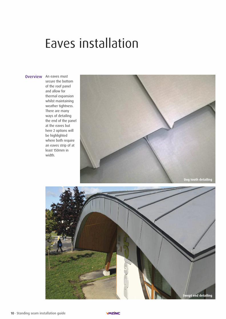
Overview An eaves mustsecure the bottomof the roof paneland allow forthermal expansionwhilst maintainingweather tightness.There are manyways of detailingthe end of the panelat the eaves buthere 2 options willbe highlightedwhere both requirean eaves strip of atleast 150mm inwidth.
Dog tooth detailing
Swept end detailing

Eaves installation
11Standing seam installation guide
VMZINC PLUS StandingSeam
First sliding clip
G3 eaves strip
Galvanised steelsupport
Plywood, 6mm thinnerthan adjacent boards
Plywood
Ventilated space
Insect mesh
VMZINC PLUS flashing
VMZINC PLUScontinuous sheet strip
VMZ Gutter Bracket
VMZ Gutter
Breather membrane
Insulation
1
23a
4
5
67
89
10
10
Eaves detail
8
7
9
2
10
11
12
1
3a
5
46
12
11
10
3b
13
13
3b
All dimensions in mm
Recommendations:Hanging gutters should have a minimum fall of 1:200. Internal gutters should have minimum falls of 1:100.
A
C1
B
150
C
Managingthermal
movement A = B = 30mm for panels shorter than 7m in lengthA = B = 50mm for panels longer than 7m in lengthC = C1 = Varies depending on the temperature during the installation. For
most situations a 6mm gap is left, however this may be increasedif the panels are long and/or installed in very hot weather –consult us for further information.
Eaves installation
12 Standing seam installation guide
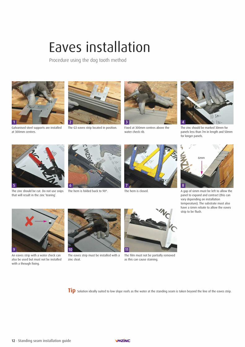
Procedure using the dog tooth method
1 2 3 4Galvanised steel supports are installedat 300mm centres.
The G3 eaves strip located in position.
5 6
Fixed at 300mm centres above thewater check rib.
The zinc should be marked 30mm forpanels less than 7m in length and 50mmfor longer panels.
The zinc should be cut. Do not use snipsthat will result in the zinc ‘tearing’.
The hem is folded back to 90º. The hem is closed. A gap of 6mm must be left to allow thepanel to expand and contract (this canvary depending on installationtemperature). The substrate must alsohave a 6mm rebate to allow the eavesstrip to be flush.
7 8
9 10An eaves strip with a water check canalso be used but must not be installedwith a through fixing.
The eaves strip must be installed with azinc cleat.
The film must not be partially removedas this can cause staining.
11
Tip Solution ideally suited to low slope roofs as the water at the standing seam is taken beyond the line of the eaves strip.
�
6mm

Eaves installation
13Standing seam installation guide
Procedure using the swept end method
1 2 3 4Mark the zinc with a template (80mm inlength).
Straighten the upstand.
5 6
Cut back the zinc. Flatten the zinc.
Fold back the upstand. Install 2nd panel. Open up the upstand. Mark the zinc at 15mm above the cutedge.
7 8
9 10Cut the zinc back. Pinch over the overlap. Hammer over the overlap.
11 12Hammer over swept end.
13Completed eaves prior to film removal.
Tip This detail is elegant but does require more time and skill to be installed properly.
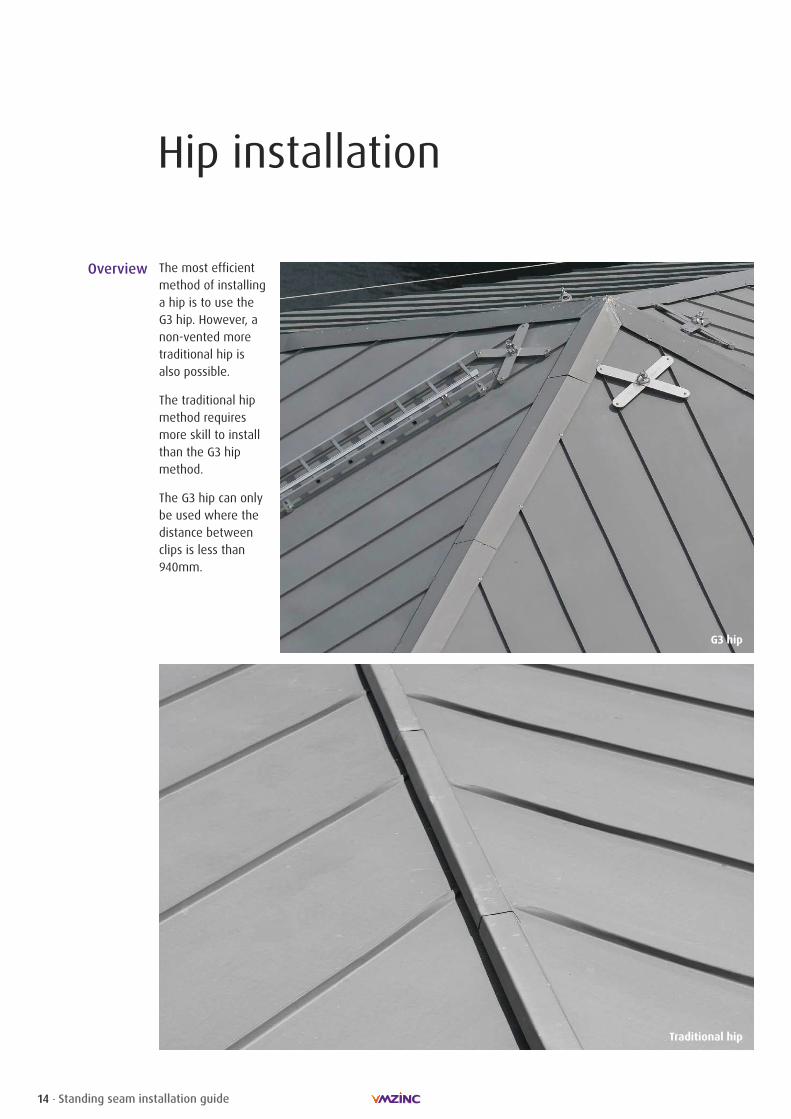
Hip installation
14 Standing seam installation guide
Overview The most efficientmethod of installinga hip is to use theG3 hip. However, anon-vented moretraditional hip isalso possible.
The traditional hipmethod requiresmore skill to installthan the G3 hipmethod.
The G3 hip can onlybe used where thedistance betweenclips is less than940mm.
G3 hip
Traditional hip
Hip installation
15Standing seam installation guide
8010
10 min.
15
185 18550
G3 hip detail
VMZINC PLUS StandingSeam
Plywood
Compression strip G3
Insect mesh
VMZINC Ridge Clip G3(fixed part)
VMZINC Ridge Clip G3(moving part)
VMZINC Hip G3
VMZINC Membrane
Clip fixing in accordancewith the specification
Ventilated space
1
2
345
6
78
9
3
41
5
6
7
9
5
6
2
810
10
All dimensions in mm
Traditional hip detail
VMZINC Standing Seam
Hip cap
Stainless steel clip
Flattened seam
Timber hip batten
Open gap softwoodboarding
Rafter
1
23
4
5
6
7
1 23 45
6 7

Hip installation
16 Standing seam installation guide
Procedure using the G3 hip method
1 2 3 4The panel is folded up over 15mm. A dog ear fold is created and the seam
is crimped.
5 6
The G3 hip is used the mark theprotective film that is then removed.
The clip is installed.
The tape is removed from thecompression strip.
The strip is installed (no gaps must beleft).
The distance between hip and 1st seammust be at least 370mm and the hipshould be flattened over 150mm.
The end of the G3 hip is folded backover 30mm.
7 8
9 10The G3 hip is hooked onto the eaves strip.G3 flashings require a 100mm overlap(with stiffening folds cut back). For slopesless than 25% the elements must besoldered together.
The G3 hip is installed into the clip andfixed with a stainless steel screw.
Tip The hip is installed from bottom to top and clips must be no more than940mm apart. The G3 hip is a kit and individual parts must not besubstituted and replaced.
Hip installation
17Standing seam installation guide
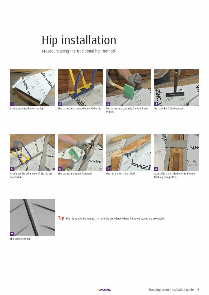
Procedure using the traditional hip method
1 2 3 4Panels are installed on the hip. The seams are crimped beyond the hip.
5 6
The seams are carefully flattened over150mm.
The panel is folded upwards.
Panels on the other side of the hip areseamed up.
The seams are again flattened. The hip batten is installed. A zinc clip is installed prior to the hipflashing being fitted.
7 8
Tip This hip cannot be vented. It is also the only detail where flattened seams are acceptable.
9The completed hip
18 Standing seam installation guide
Ridge installation
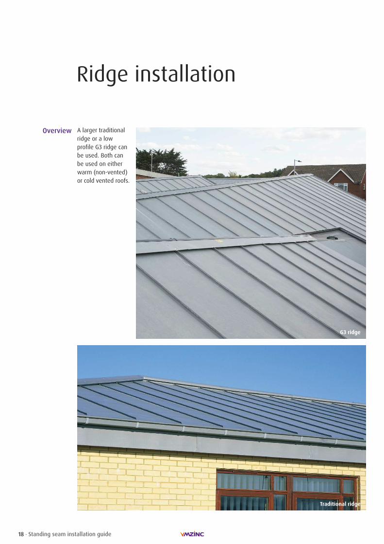
Overview A larger traditionalridge or a lowprofile G3 ridge canbe used. Both canbe used on eitherwarm (non-vented)or cold vented roofs.
G3 ridge
Traditional ridge
19Standing seam installation guide
Ridge installation
8010
10 min.
15
185 18550
G3 ridge detail
VMZINC PLUS StandingSeam
Plywood
Compression strip G3
Insect mesh
VMZINC Ridge Clip G3(fixed part)
VMZINC Ridge Clip G3(moving part)
VMZINC Ridge G3
VMZINC Membrane
Clip fixing in accordancewith the specification
Ventilated space
1
2
345
6
78
9
3
41
5
6
7
9
5
6
2
VMZINC PLUS StandingSeam
Plywood
Sprocket piece
Insect mesh
Ventilated space
VMZINC saddle piece
VMZINC PLUS sheet clip,0.8mm thick, width80mm, 2 per m
VMZINC folded clip, 2 per m
VMZ ridge piece
VMZINC Membrane
1
2
3
45
6
7
8
910
Traditional ridgedetail
80
5530
50
170
1 2
3
4
5
6
79
8
10
8
810
10
All dimensions in mm

20 Standing seam installation guide
Ridge installationProcedure using the G3 ridge method
1 2 3 4Lay a G3 ridge cap on the axis of theridge and cut the film back.
5 6
Install the G3 clips on each side with thebottom of the clip lined up with the cutfilm. Insert the clip into the seam.
Stick the compression strip between theseams. The strip should be 10mm belowthe upstand and the length of the stripshould be 20mm wider than the c/cdistance between the seams.
The angle of the G3 ridge can bealtered. For low sloped roofs more openG3 ridges can be ordered. The ridge isinserted into the clips.
Connector pieces should be fitted beforethe ridge is installed.
Stainless steel screws must be used toattach the clip to the ridge piece.
For ridge end piece. Cut back hem onridge cap by 65mm.
7 8
9 10Notch ridge at 30mm and 35mm and atangle of the roof.
Fold end ridge into position. Fix end cap with stainless steel screwsinto verge.
11
The panels are installed with a 15mmupstand (25mm should be used for awarm roof). An airspace should be leftfor vented roofs and should beprotected with insect mesh.
Tip The fixing clip can be moved up and down the seam using a mallet if necessary. As with the G3 hip the G3 ridge is a kitand individual parts should not be replaced and swapped.
21Standing seam installation guide
Ridge installationProcedure using the traditional ridge method
1 2 3 4Mark the zinc at 100mm. Cut away return fold on the profiles.
5 6
Create a dog ear fold. Fold up the panel.
Create fold on panel upstand. Finish fold on panel upstand. Seam panels together. Fit saddle piece and pinch at seam.
7 8
9 10Fit clip for ridge flashing. Insert ridge flashing. Do not partially remove film.
11
Tip As with all details, the plastic film can be scored with a piece of zinc and removed leaving a clean sharp line. Under no circumstances must the film be allowed to `flap` as this will result in staining.

22 Standing seam installation guide
Verge installation
Overview A verge can becreated either byusing a G3 whichmoves the standingseam away from theridge or a standingseam verge. In bothcases the downstandshould be at least60mm.
G3 verge
Standing seam verge

20 min.
23Standing seam installation guide
Verge installation
All dimensions in mm
Standing seamverge detail
G3 verge detail
10
150 min. to 370 max.
VMZINC PLUS StandingSeam
VMZINC PLUS G3 EavesStrip pack
Ventilated space
Plywood
VMZINC Membrane
1
2
3
4
5
VMZINC PLUS StandingSeam
Ventilated space
VMZ stainless steelSliding Clip (adjusted onsite)
VMZINC PLUS Fascia
VMZINC PLUScontinuous edgeflashing
Wall
Breather membrane inaccordance with thespecification
Plywood
1
2
3
4
5
6
7
8
12
3
4
5
2
2
3
4
6
8
1
75
24 Standing seam installation guide
Verge installation
1 2 3Fit the verge strip into the stiffener andfix with nails. The strips should overlapby 50mm.
The standing seam panels are fitted inthe normal fashion and by being hookedinto the verge strip with a 30mm hem.The distance between the verge and thefirst seam must be at least 150mm but nomore than 370mm.
Fix the stiffeners at 300mm centres.
Tip The G3 verge can be used on curved roofs but the radius must be at least3m. However the verge must be cut at interval of 1/10 of the radius. Forexample for a 5m radius roof the verge strip must be notched every 500mm.
Procedure using the G3 verge method
1 2 3 4Position the standing seam panel.
5 6
Fit the verge strip. Crimp the standing seam at the verge.
Crimped seam. Completed verge.
Install a zinc clip with nails leaving a20mm space with the verge.
Tip The 20mm space between the verge and wall acts as a drip and must be respected.
Procedure using the standing seam verge method

25Standing seam installation guide
Transverse junction installation
Overview
Double welt joints
Step joint
Standing seam zincroofing panels canbe joined usingeither steps orwelted joints.
Step joints can beused with roofpitches down to 3º.They allow forexpansion andcontraction as wellas ventilation.
Double welt joints(also known as across welt withcontinuously solderedundercloak) are notrecommended below14º. They also onlyallow very limitedthermal expansionand contraction.
26 Standing seam installation guide
Transverse junction installation
All dimensions in mm
Step joint detail
Double welt jointdetail
80
60
150
VMZINC PLUS StandingSeam
VMZINC saddle piece
VMZINC PLUS sheet clip,0.7mm thick, width80mm, 2 per m
Insect mesh
VMZINC PLUScontinuous folded strip
VMZINC PLUS eavesapron strip
Plywood, main sheeting
Plywood, 5mm thinnerthan adjacent mainsheeting
Ventilated space
VMZINC Membrane
1
23
4
5
6
78
9
10
1
2
3
46
7
8
910
7
71
5
3 9
VMZINC PLUS StandingSeam panel
Continuous, solderedcleat
Fixing clip
Open-gap boarding
1
2
3
4
150
10
100
30
30
2015
25
15
12
3
4
3
41
2

27Standing seam installation guide
Transverse junction installation
1 2 3 4Pinch saddle piece into place.
5
Fit eaves strip as per the eaves.(See page 8)
A G3 eaves strip can also be used.
Fit the upper panels as per the eaves.(See page 8)
Create upstand as per ridge. (See page 16)
Tip A double welt junction requires some of the standing seam on the lower panel to be cut back. This does allow for a verylimited amount of thermal movement but means that it cannot be used below 14º. The use of a step allows thermalmovement, the detail to be used at 3º, and has the added benefit of allowing a ventilation entry and exit route.
1 2 3 4Solder welted strip onto panel 150mmbelow the water check.
Hook upper panel into place. Complete double welt by gentlyhammering a wooden block onto thelower hem.
Fold 25mm hem on panel and removepatina 150mm further down panel.
Tip A roof step joint can allow the roof to ventilate as well as permitting thermal expansion. This joint can also be useddown to the minimum slope of 3º.
Procedure using the step joint method
Procedure using the double welt joint method
28 Standing seam installation guide
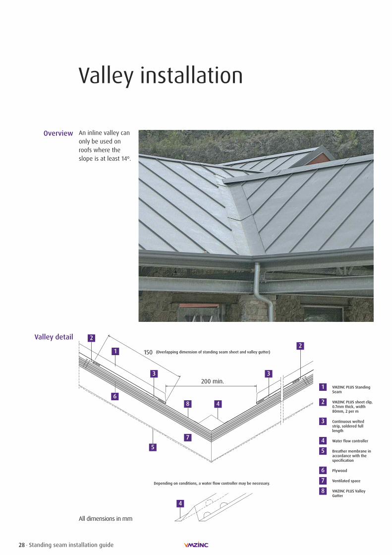
Valley installation
Overview An inline valley canonly be used onroofs where theslope is at least 14º.
All dimensions in mm
Valley detail
VMZINC PLUS StandingSeam
VMZINC PLUS sheet clip,0.7mm thick, width80mm, 2 per m
Continuous weltedstrip, soldered fulllength
Water flow controller
Breather membrane inaccordance with thespecification
Plywood
Ventilated space
VMZINC PLUS ValleyGutter
1
2
3
4
5
6
7
8
1
4
5
6
7
(Overlapping dimension of standing seam sheet and valley gutter)
Depending on conditions, a water flow controller may be necessary.
4
8
2
3 3
2
29Standing seam installation guide
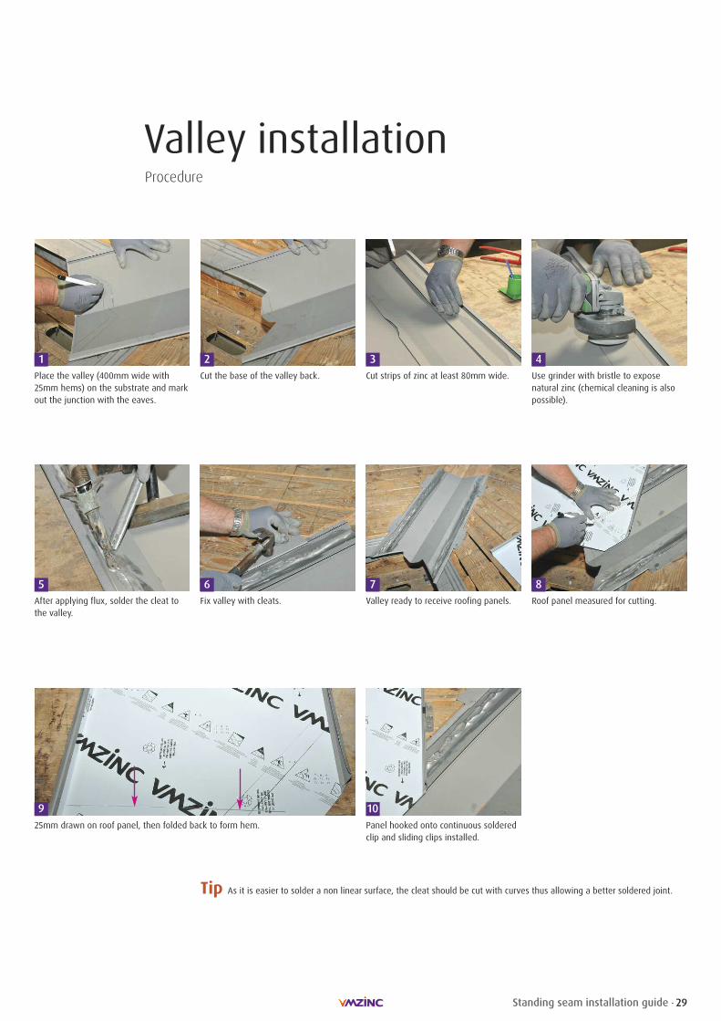
Valley installation
1 2 3 4Cut the base of the valley back.
5 6
Cut strips of zinc at least 80mm wide. Use grinder with bristle to exposenatural zinc (chemical cleaning is alsopossible).
After applying flux, solder the cleat tothe valley.
Fix valley with cleats. Valley ready to receive roofing panels. Roof panel measured for cutting.
7 8
925mm drawn on roof panel, then folded back to form hem. Panel hooked onto continuous soldered
clip and sliding clips installed.
10
Place the valley (400mm wide with25mm hems) on the substrate and markout the junction with the eaves.
Tip As it is easier to solder a non linear surface, the cleat should be cut with curves thus allowing a better soldered joint.
Procedure

50 m
in.
80 m
in.
60
Upstand slope 1° (2%)
30
150 min.
Detail between the welted panels
4030
15
30 Standing seam installation guide
Fascia installation
Overview
Fasciadetail
VMZINC PLUS StandingSeam
VMZINC PLUS sheet clip,0.7mm thick, width80mm, 2 per m
VMZINC PLUS continuouseaves apron strip,0.7mm thick
Plywood, 5mm thinnerthan adjacent boards
Plywood
VMZINC PLUS boxedgutter
VMZINC PLUScontinuous bracket,0.7mm thick
VMZINC PLUS fascia andsoffit welted panels,400mm x 2000mm
Breather membrane inaccordance with the specification
VMZINC PLUScontinuous welt piece
Insect mesh
Plywood laid to fall onpackers
VMZINC PLUScontinuous sheet strip,0.7mm thick
Ventilated space
VMZINC PLUS saddlepiece at panel junctionsof fascia and soffit
1
2
3
4
5
6
7
There are many waysto clad parapets andfascias. The use of acoulisseau piece isoften the mostappropriate solution.The coulisseau canbe omitted thuscreating a flat lockjoint but the fasciawill not sit as flat.
All dimensions in mm
8
9
10
11
12
13
14
15
12
3
4
5
6 7
8
9
10
11
12
13
14
15 2
14
2
5
8
8
13
Tip Internal guttersrequire expansionjoints every 6mand in some casesbetween fixedpoints which maybe less than 6m.
11

31Standing seam installation guide
Fascia installation
1 2 3 4Fabricate the soffit panel with a 25mmhem and 2 x 25mm return folds.
5 6
Install soffit. Install adjoining soffit.
Open up top fold. Insert coulisseau. Fold down tabs. Fit fascia with a cleat.
7 8
9 10Fit adjoining flashing and turn up folds. Fit 2nd coulisseau.
Fix a base flashing to the bottom of thesoffit using screws.
Tip Individual pieces for fascias should never be more than 3m in length or600mm deep. Parapets that are over 500mm in width should be consideredas roofs and joined with standing seams and have slopes of at least 3º.Slopes of 1º are acceptable for parapets less than 500mm wide.
Procedure

32 Standing seam installation guide
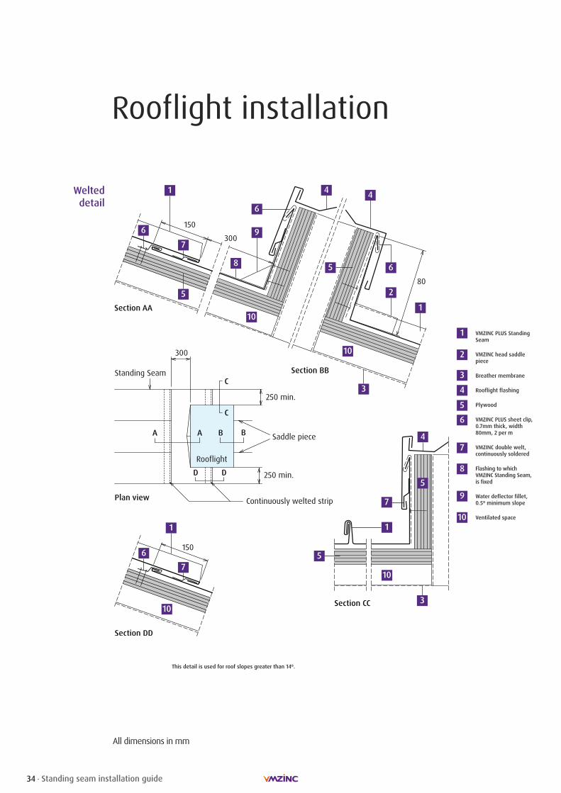
Rooflight installation
Overview The two mostcommonly usedtechniques are: the solderedsolution for roofswith a slopebetween 3º and 14º,and the weltedsolution for roofswith a slope greaterthan 14º.
Soldered solution
Rooflight head detail for welted solution
Rooflight base detail for both soldered and welted solutions

33Standing seam installation guide
Rooflight installation
All dimensions in mm
Soldereddetail
VMZINC PLUS StandingSeam
VMZINC head saddlepiece
Breather membrane
Rooflight flashing
Plywood
VMZINC PLUS sheet clip,0.7mm thick, width80mm, 2 per m
VMZINC double welt,continuously soldered
VMZINC Standing Seam,folded, laid flat andsoldered with space atfillet allowing expansion
Water deflector fillet,0.5º minimum slope
Ventilated space
1
2
3
4
5
6
7
8
9
Penetrations must not interrupt more than three seams.
Above the upper level of the rooflight, expansion of thezinc sheeting must be towards the ridge not the eaves.
This detail is used for roof slopes between 3º and 14º.
1
2
3
4
5
6
7
8
9
1
6
4
5
5
5
1
4
10
10
10
10
3
34 Standing seam installation guide
Rooflight installation
150
Welteddetail
VMZINC PLUS StandingSeam
VMZINC head saddlepiece
Breather membrane
Rooflight flashing
Plywood
VMZINC PLUS sheet clip,0.7mm thick, width80mm, 2 per m
VMZINC double welt,continuously soldered
Flashing to whichVMZINC Standing Seam,is fixed
Water deflector fillet,0.5º minimum slope
Ventilated space
1
2
3
4
5
6
7
8
9
10
1
2
3
4
5
6
8
9
1
6
4
5
10
10
7
5
5
1
4
10
10
76
1
7
6
This detail is used for roof slopes greater than 14º.
All dimensions in mm
3
35Standing seam installation guide
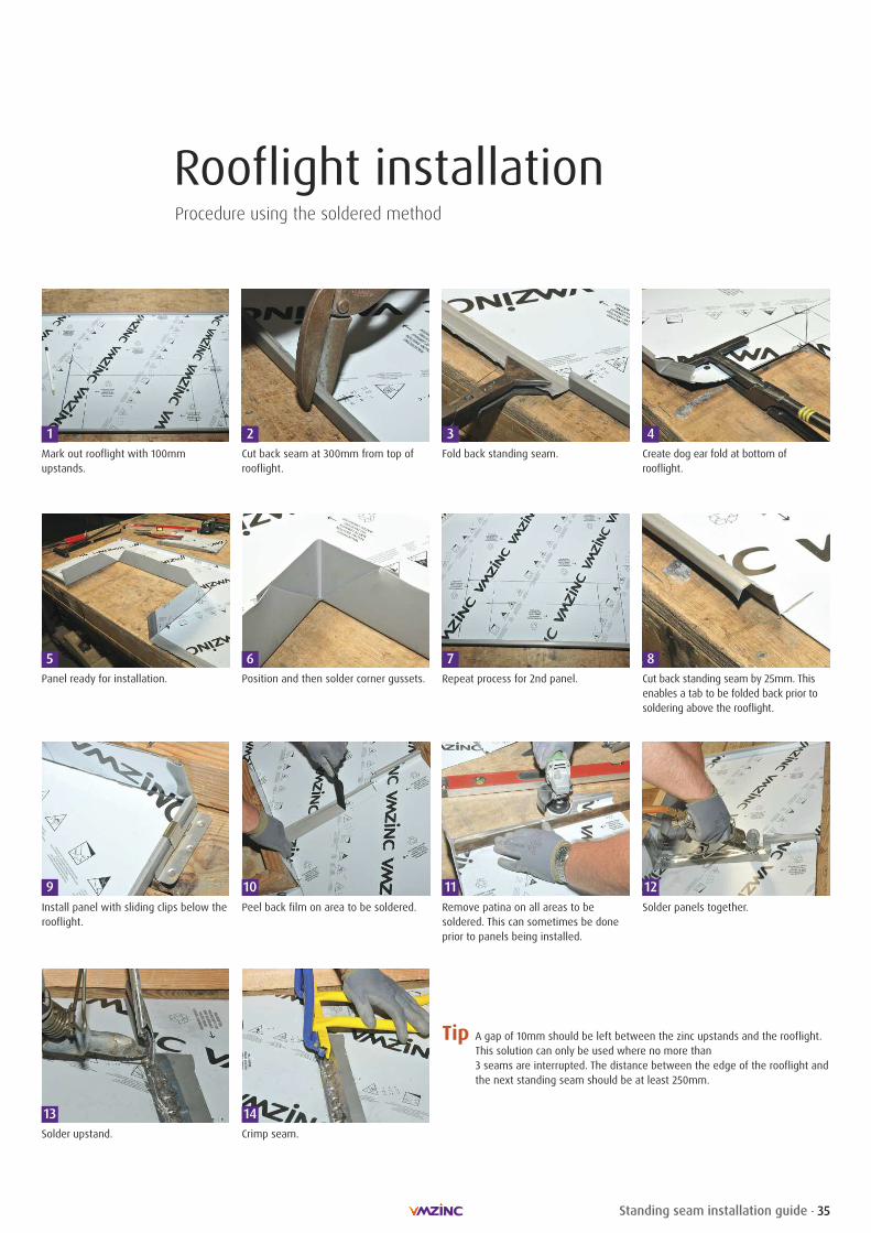
Rooflight installation
1 2 3 4Mark out rooflight with 100mmupstands.
Cut back seam at 300mm from top ofrooflight.
5 6
Fold back standing seam. Create dog ear fold at bottom ofrooflight.
Panel ready for installation. Position and then solder corner gussets. Repeat process for 2nd panel. Cut back standing seam by 25mm. Thisenables a tab to be folded back prior tosoldering above the rooflight.
7 8
9 10Install panel with sliding clips below therooflight.
Peel back film on area to be soldered. Remove patina on all areas to besoldered. This can sometimes be doneprior to panels being installed.
11 12Solder panels together.
13 14Solder upstand. Crimp seam.
Tip A gap of 10mm should be left between the zinc upstands and the rooflight.This solution can only be used where no more than 3 seams are interrupted. The distance between the edge of the rooflight andthe next standing seam should be at least 250mm.
Procedure using the soldered method

36 Standing seam installation guide
Rooflight installationProcedure using the welted method
1 2 3 4Cut zinc out.
5 6
Create dog ear fold at bottom ofrooflight.
Create safety check at top of panel.
Fabricate 2nd panel. Remove patina from all areas to besoldered.
2 panels installed. Solder back plate into position.
7 8
9 10Alternative positioning of welted joint. Back plate with soldered strip. Back plate installed as a double welt.
11
Mark out rooflight and include 100mmupstands.
Tip If the rooflight is over 1m wide a water deflector (gusset) should be moulded in to the rear upstand in order to guidethe water left and right of the obstacle.
37Standing seam installation guide
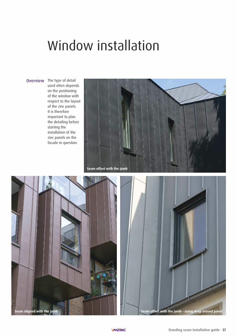
Window installation
Overview The type of detailused often dependson the positioningof the window withrespect to the layoutof the zinc panels. It is thereforeimportant to planthe detailing beforestarting the installation of thezinc panels on thefacade in question.
Seam aligned with the jamb
Seam offset with the jamb
Seam offset with the jamb - using wrap around panel
38 Standing seam installation guide
Window installation
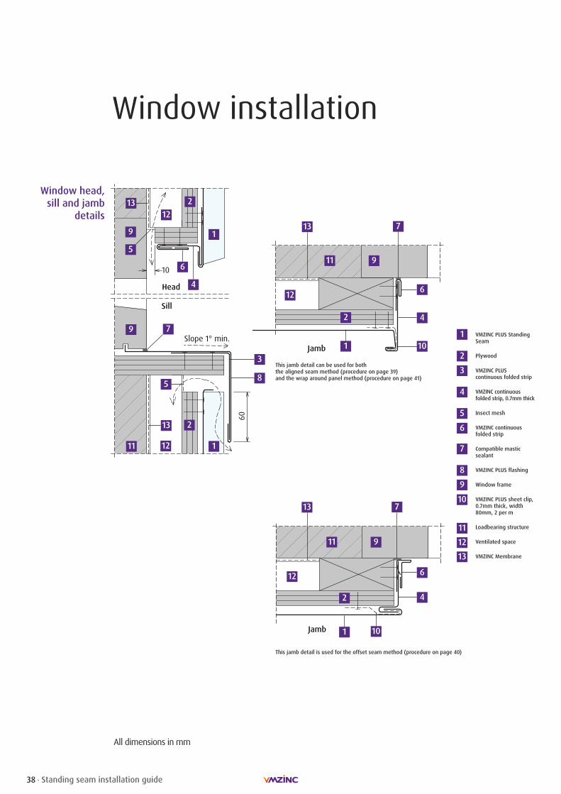
All dimensions in mm
60
Head
10
Slope 1° min.
Sill
Jamb
Window head,sill and jamb
details
VMZINC PLUS StandingSeam
Plywood
VMZINC PLUScontinuous folded strip
VMZINC continuousfolded strip, 0.7mm thick
Insect mesh
VMZINC continuousfolded strip
Compatible masticsealant
VMZINC PLUS flashing
Window frame
VMZINC PLUS sheet clip, 0.7mm thick, width80mm, 2 per m
Loadbearing structure
Ventilated space
VMZINC Membrane
1
2
3
4
5
6
7
8
9
10
11
1
6
12
2
7
12
9
1
13
6
2
9
9
12
12
13
2
4
5
58
3
7
1 10
13
11
11
13
This jamb detail can be used for boththe aligned seam method (procedure on page 39)and the wrap around panel method (procedure on page 41)
This jamb detail is used for the offset seam method (procedure on page 40)
Jamb
7
2
1
9
12
11
13
4
4
10
6

39Standing seam installation guide
Window installationProcedure using the aligned seam method
1 2 3 4The 1st panel is installed aligned withthe jamb.
The panel below the window with a15mm return is installed using a singlelock.
5a 6
The sill is made with a downstand of atleast 60mm.
The sill is notched back by 50mm. Caremust be taken to use a tool that will notleave a tear in the zinc.
5a. The back of the sill must be foldedinto a dog ear.
The sill is installed and the foldedaround the seam.
The jamb receiver strip is fabricated. The strip is notched to create a frictiongrip.
7 8
9 10The strip is installed. A standing seam jamb is made with a
50mm return for the top.The jamb with the friction grip isinstalled.
11 12The head receiver strip is fitted and ameasurement for the head flashing taken.
13 14The head flashing is made. The head flashing is fitted using the
friction grip and slotted holes for screws.
15The next standing seam panel isinstalled with sliding clips.
Remove plastic film at the end of the job.
5b. The sill downstand is then notched.
5b
Tip Always remove the protective film that will get stuck in the joints. The film must be removed by being scored with a piece of zinc as this leaves a clean line.
16

40 Standing seam installation guide
Window installationProcedure using the offset seam method
1 2 3 4The panel is offered up to the window. A hem for a single welt is formed along
with a 90º return for the sill.
5 6
The panel is fixed in place with a fixedclip.
The window sill is formed with a 50mmupstand.
Window sill prior to installation. Sill in position. Jamb receiver strip installed and jambmeasured.
Jamb with reveal joint prior to installation.
7 8
9
10
Installed jamb.
Head strip fitted into receiver strip.
Following panel measured up.
11
12Panel cut out.
13Panel installed and film stripped.
Tip The horizontal joint can be aligned with the sill or further up the jamb. This flashing is excellent in very exposed areas.

41Standing seam installation guide
Window installationProcedure using the wrap around panel method
1 2 4The window is traced onto back of thestanding seam panel. A line 30mm backis drawn and then the zinc is cut out.
An upstand is formed on the panel.
5 6
The sill (as before) is installed.
Jamb receiver strip is installed. Standing seam jamb installed. Jamb crimped to a single lock.
Head trim fitted into receiver strip.
7
8 9
10
Hem on panel folded back.
Completed window.Tip A wuko tool can be used to form the standing seams on the wrap aroundpanel and the jamb. This detail is not suited to very exposed facades.
3The panel is installed around the window.
42 Standing seam installation guide
Installing zinc
Use a professional
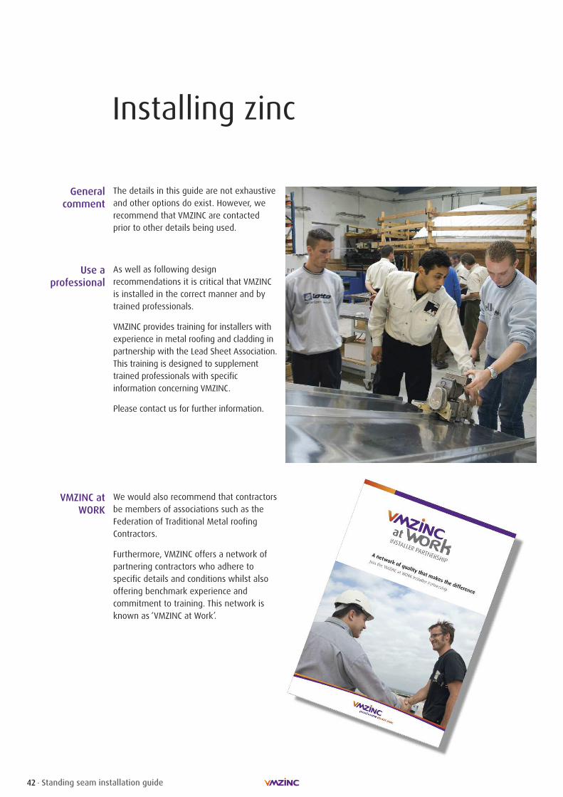
As well as following design recommendations it is critical that VMZINCis installed in the correct manner and bytrained professionals.
VMZINC provides training for installers withexperience in metal roofing and cladding inpartnership with the Lead Sheet Association.This training is designed to supplementtrained professionals with specificinformation concerning VMZINC.
Please contact us for further information.
VMZINC atWORK
We would also recommend that contractorsbe members of associations such as theFederation of Traditional Metal roofingContractors.
Furthermore, VMZINC offers a network ofpartnering contractors who adhere tospecific details and conditions whilst alsooffering benchmark experience andcommitment to training. This network isknown as ‘VMZINC at Work’.
The details in this guide are not exhaustiveand other options do exist. However, werecommend that VMZINC are contactedprior to other details being used.
Generalcomment
43Standing seam installation guide
Installing zinc
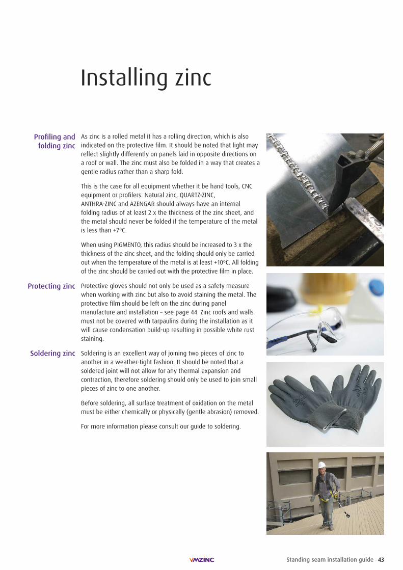
As zinc is a rolled metal it has a rolling direction, which is alsoindicated on the protective film. It should be noted that light mayreflect slightly differently on panels laid in opposite directions ona roof or wall. The zinc must also be folded in a way that creates agentle radius rather than a sharp fold.
This is the case for all equipment whether it be hand tools, CNCequipment or profilers. Natural zinc, QUARTZ-ZINC, ANTHRA-ZINC and AZENGAR should always have an internalfolding radius of at least 2 x the thickness of the zinc sheet, andthe metal should never be folded if the temperature of the metalis less than +7ºC.
When using PIGMENTO, this radius should be increased to 3 x thethickness of the zinc sheet, and the folding should only be carriedout when the temperature of the metal is at least +10ºC. All foldingof the zinc should be carried out with the protective film in place.
Protective gloves should not only be used as a safety measurewhen working with zinc but also to avoid staining the metal. Theprotective film should be left on the zinc during panelmanufacture and installation – see page 44. Zinc roofs and wallsmust not be covered with tarpaulins during the installation as itwill cause condensation build-up resulting in possible white ruststaining.
Soldering is an excellent way of joining two pieces of zinc toanother in a weather-tight fashion. It should be noted that asoldered joint will not allow for any thermal expansion andcontraction, therefore soldering should only be used to join smallpieces of zinc to one another.
Before soldering, all surface treatment of oxidation on the metalmust be either chemically or physically (gentle abrasion) removed.
For more information please consult our guide to soldering.
Profiling andfolding zinc
Protecting zinc
Soldering zinc

44 Standing seam installation guide
Installing zinc
The protective film should be removed from the zinc panels uponcompletion of the facade or roof all at the same time.
The protective film should remain on the zinc no longer than 60days after the installation of the panels. Make sure that othertrades do not contaminate zinc panels after the film is removed.
The film must not be partially removed during installation for theremaining film to be removed at a later date, as this is likely toallow water to become trapped between the zinc and the partiallyremoved film resulting in staining. It should be noted that moststains are very difficult to remove.
If fully filmed sheets are being used to form panels, which maymake it difficult to remove the film after installation, the film canbe scored by using a piece of zinc (greatly reduces scratching ofthe pre-weathering). This must be done on an area of the panelwhere water cannot build up, i.e. in the reveal of a cassette paneland not on the face of a panel. The scoring must also be done soas to leave a clean well-adhered edge to the film.
Once the film has been removed it must not be covered withtimber, tarpaulins, etc as these will trap water and induce staining.
Protective film
Staining resulting from partial removal of protective film.
Partial removal of protective film.
45Standing seam installation guide
Maintenance and storage
Minimumrequirements
andnormal
maintenance
Although zinc is a metal that requires very little maintenance andthe rinsing effect of rain water is often sufficient to keep the zincin ideal condition the following precautions should be followed.The roof should be regularly inspected and any foreign matter suchas leaves, grass and other deposits should be removed. Specialattention should be given to gutters, ensuring that they are cleanand not blocked thus allowing the free flow of water (flat gutterswhich result in standing water are not recommended). Thismaintenance shall be at the owner`s expense after the installationwork has been completed.
Normal foot traffic use implies traffic reduced to a strict minimumfor normal maintenance defined above and for other work, suchas installation and servicing of aerials, etc.
It is advisable to take all the precautions and useful provisionsnecessary so as not to cause any puncturing of the flat parts ordeformation of the joints, roll capping, roof vents, etc. Care mustalso be taken to clean footwear prior to walking on the roof.
In the case where technical equipment requiring frequentinspections (air conditioning, for example) is installed on the roof,certain adaptive arrangements such as walkways should beconsidered.
As indicated above, the rinsing effect of the rain will often meanthat no other cleaning is necessary. However, it is possible towash the zinc with warm water and a mild detergent.
The zinc must always be cleaned in the direction of the grain ofthe metal. Pressure washers are not recommended. Cleaning withdetergent can be supplemented with application of a very smallamount of mineral oil. The zinc must be completely dry prior toany application of mineral oil. It is always advisable that a smalltest area is cleaned and left for 24 hours prior to proceeding to alarger area.
Due to the self healing nature of zinc we would recommend thatsmall scratches be left to heal on their own. We do notrecommend the use of touch-up paint.
Foot traffic
Cleaning
Scratches
Gutters must be regularly cleaned.
Boots should be cleaned prior to working on a zinc roof.
46 Standing seam installation guide
Maintenance and storage
Storage
In coastal areas salty water can stagnate on all surfaces includingzinc. When the water evaporates it is possible that this can leavea white stain.
On surfaces that are rinsed by rainwater the majority of thestaining will be removed. However, on non-rinsed facades andsoffits it is possible that these stains will build up and be moreprominent.
The use of the Pigmento and Strat range reduces staining on un-rinsed surfaces and therefore should be considered for coastalenvironments.
It should be noted that this staining is purely aesthetic. Allprojects within 1km of salt water should be considered as ‘severecoastal’ and within 20km as ‘coastal’.
The zinc sheets, coils, and formed pieces must be stored in a well-ventilated, sheltered and dry area where temperaturevariation is kept to a minimum.
� Temperature variations can cause condensation build-up, that inturn will cause zinc hydroxide (white rust) to form. Ensure thatthe zinc is stored in an area without great temperature variations.Zinc hydroxide forms when the surface of zinc comes into contactwith humidity without carbon dioxide. Zinc hydroxide provides noprotection and leaves unattractive, indelible marks on the zinc.Consequently, we do not recommend installing any panel thathas been affected by zinc hydroxide
� The sheets, coils and formed pieces should be separated fromthe ground by pallet or similar storage device to allowsufficient ventilation of the zinc
� Pallets or similar storage device should allow the zinc sheet tobe stored flat to reduce risk of deformation
� It is recommended that the coils be stored in their originalpackaging
If the coils are to be stacked due to lack of storage space thefollowing recommendations must be followed:
� If coils are delivered on their horizontal axis, the pallets mustbe stored in their original packaging and individually onseparating racks
� If coils are delivered on their vertical axis the pallets must bestored on top of one another with a maximum of 4 pallets forstability reasons
� Zinc must never be stored outside
Salt
47Standing seam installation guide
Sustainable performance
Low energy used in the
manufacturingprocess
VMZINC rolled zinc products are used in construction industries throughout the world for theirsustainability, distinctive appearance, and low maintenance requirements. As with VMZINCfacade and rainwater systems, manufacturing processes for our standing seam systempresents a low environmental impact, particularly with regard to energy expenditure.
Less energy is required to extract zinc from the ground than the other principal metals,and is even more favourable for recycled zinc. Such minimal use of energy in theproduction of zinc clearly indicates its contribution to sustainable development.
95% of old rolled zinc recovered every year in Western Europe, currently estimated at100,000 tonnes, is reused. This represents savings in mining resources of between 1 and2 million tonnes.
The VMZ standing seam system benefits from zinc’s self-protecting patina which developsas a result of exposure to water and carbon dioxide. Over the last 50 years the quantity ofsulphur dioxide in the atmosphere has been greatly reduced. SO2 being the key agent ofcorrosion means that corrosion rates are now 1μm per year. With an initial thickness of0.7mm, the estimated life span of rolled zinc is over a hundred years.
VMZINC undertakes Life Cycle Analysis (LCA) tests on its products and publishes Environmental Product Declarations (EPDs), such as BRE Environmental Profiles, availablefrom our website www.vmzinc.co.uk and www.greenbooklive.com. These provide userswith comprehensive, reliable and transparent information on relevant environmentalcharacteristics. The information is also used by VMZINC as the basis for its eco-design approach.
Low corrosion,long life
Recycledmaterial
A naturalmaterial
Environmental profiles measure the impacts of a construction material, product orbuilding system throughout its life, not only during its manufacture, but also its use in abuilding over an 80 year period. This includes its extraction, processing, use andmaintenance and its eventual disposal.
VMZINC has been audited and reviewed by BRE Global. The Life Cycle Assessment (LCA)modelling derives a Certified Environmental Profile and a Green Guide rating has been produced.
A wide range of zinc roofing and cladding systems has been audited with the systemsreceiving a Green Guide rating of up to A+. These profiles can then be applied to theBREEAM (BRE Environmental Assessment Method) allowing VMZINC to contribute toschemes such as the Code for Sustainable Homes.
Since 2009, VMZINC has been OHSAS 18001 certified, thus conforming to occupationalhealth and safety management systems.
VMZINC manufacturing plants have conformed to ISO 14001 since 2004/5 so processesare strictly controlled to ensure that emissions are significantly below the nationalregulation threshold.
ISO 9001 is the internationally recognised standard for the quality management ofbusinesses and applies to all Umicore/VMZINC products and services. Certification wasoriginally obtained in 1997 and updated in November 2003 to conform to ISO 9001:2000.
Standards

SubjectThe subject of this document is intended for specifiers (building project architectsand design teams) and users (companies responsible for installation on the building site) of the designated product or system. Its purpose is to provide themain information, text and diagrams, relating to specification and installation. Anyuse or specification outside the area of use and/or specifications contained in thisbrochure requires specific consultation with the Umicore technical departments.This does not commit the latter to any responsibility with regard to the feasibilityof the design or implementation of these projects.
Countries of applicationThis document applies exclusively to the specification and installation of the designated products or systems on building sites in the United Kingdom and the Republic of Ireland.
Qualifications and reference documentsPlease note that the specification of all construction systems for a given buildingremains the exclusive responsibility of its design team, who must, in particular,ensure that the specified products are suitable for the purpose of the building andcompatible with the other products and techniques used. Please note that thecorrect use of this manual requires knowledge of VMZINC materials and of thezinc roofing profession. While construction is underway all standards in force mustbe respected.
ResponsibilityThe specification and installation of VMZINC products manufactured by Umicoreare the sole responsibility of the architects and building professionals who mustensure these products are used in a way suited to the end purpose of the construction and that they are compatible with other products and techniquesused. The specification and installation of the products implies respecting thestandards in force and the manufacturer’s recommendations. In this regard, Umicore publishes and regularly updates specification and installation manuals forspecific geographic areas and provides training courses. All the information on thelatter can be obtained from the VMZINC team. Unless otherwise agreed in writ-ing, Umicore cannot be held responsible for any damages resulting from a specification or installation that does not respect all of Umicore’s specificationsand the above standards and practices.
Umicore Marketing Services UKCollier House,Mead Lane,Hertford, Herts, SG13 7AX
Tel 01992 822288Fax 01992 584460Web www.vmzinc.co.ukWeb www.vmzinc.ie