steam engine collection · 2019-02-27 · steam engine collection the new england museum of...
TRANSCRIPT

STEAM ENGINE COLLECTION
The New England Museum of Wireless And SteamFrenchtown Road ~ East Greenwich, R.I.
International Mechanical Engineering Heritage CollectionDesignated September 12, 1992
The American Society ofMechanical Engineers

INTRODUCTION
It has been said that an operating steam engine is ‘visual music’. The New EnglandMuseum of Wireless and Steam provides the steam engine enthusiast, the mechanical engineerand the public at large with an opportunity to experience the ‘music’ when the engines are insteam. At the same time they can appreciate the engineering skills of those who designed theengines.
The New England Museum of Wireless and Steam is unusual among museums in itsfocus on one aspect of mechanical engineering history, namely, the history of the steam engine.It is especially rich in engines manufactured in Rhode Island, a state which has had an influenceon the history of the steam engine in the United States out of all proportion to its size andpopulation. Many of the great names in the design and manufacture of steam engines receivedtheir training in Rhode Island, most particularly in the shops of the Corliss Steam Engine Co. inProvidence.
George H. Corliss, an important contributor to steam engine technology, founded hiscompany in Providence in 1846. Engines that used his patent valve gear were built in largenumbers by the Corliss company, and by others, both in the United States and abroad, eitherunder license or in various modified forms once the Corliss patent expired in 1870. The NewEngland Museum of Wireless and Steam is particularly fortunate in preserving an example of aCorliss engine built by the Corliss Steam Engine Company. This is one of four known enginesof this type in the United States. The museum also has in its collection two other steam enginesthat employed the Corliss valve gear, but were made by the William A. Harris Steam Engine Co.in Providence. This conjunction of engines gives the visitor an unusual opportunity to study andappreciate different versions of this uniquely American engine, which was also used insubstantial numbers outside the United States, particularly in Britain.
The various engines on display at the museum represent machines constructed between1868 and about 1911. This was the heyday of the stationary engine before the arrival of the steamturbine and the ready availability of electric power provided by a utility company. During thistime businesses of all kinds from engineering companies, to textile manufacturers, to printingplants, and so on, employed steam engines to provide the power for their operations. The largerplants would have engines capable of providing several hundred horsepower and requiring thefull-time attention of several enginemen and attendants. Smaller plants needed engines that couldoperate safely and reliably for the duration of the working day with only minimal attention.Those requirements influenced the design of steam engines. The operators of larger plants wereparticularly concerned with efficiency. Engine efficiency is particularly dependent on the designof the valve gear that controls the admission of steam to the engine cylinder and its release fromthe cylinder once its energy has been extracted. Numerous forms of valve gear have beeninvented, in fact it has been said that at one stage in the nineteenth century the U.S. Patent Officereceived applications for steam engine valve gears at the rate of about one a week.
With the application of the steam engine to electrical generation after 1881, substantialattention was devoted to ensuring satisfactory speed regulation. Speed control is a function ofthe governor. A number of varieties of governors - not nearly as many as the varieties of valvegear - have been invented, and the New England Museum’s exhibits provide a number ofinteresting examples of both valve gear and governor mechanisms.
While the visitor to the museum will undoubtedly pay particularly close attention to suchthings as the overall form of the engine, the details of its operation, and its various designfeatures, a sense of the role of the steam engine both in mechanical engineering history andgeneral history should be kept in mind.
The steam engine in some sense may be said to have ‘made’ the mechanical engineer. Itrequired levels of workmanship beyond those of the millwrights who built the early wind and

water mills. It led to the development of manufacturing methods, and it improved the quality ofengineering materials. Studying the engines in the New England Museum’s collection shouldstimulate the visitor to think about how the parts for the engines were made and how those partswere made sufficiently strong to withstand the forces they experienced. This is the essence ofmechanical engineering, and those nineteen century mechanical engineers who solved thoseproblems laid the foundations of the modern profession.
Rhode Island was a particular contributor to the development of the mechanicalengineering profession. A number of important steam engine manufacturers, including theCorliss Steam Engine Co., Thurston, Greene & Co., Fairbanks, Bancroft Co. (later the CorlissSteam Engine Co.), Rice and Sargent Co., Armington & Sims Co., Providence Steam EngineCo., and William A. Harris Steam Engine Co. had their plants in Providence. The CorlissCompany was an especially important incubator of engineers who subsequently made importantcontributions to engineering. Early in their careers Corliss employed such men as WilliamSellers, founder of the William Sellers Co., machine tool builders, Alexander Holley, whobrought the Bessemer steel making process in the United States, Edwin Reynolds, who becamechief engineer for the Allis-Chalmers Co. in Milwaukee, and Nathanael Herreshoff, whoprobably designed more types of steam engines than any other engineer.
The American Society of Mechanical Engineers also has strong links to the mechanicalengineering tradition of Rhode Island. Two of the leading founders of the Society had RhodeIsland connections. Robert H. Thurston, the first president of the Society was born inProvidence and worked at his father’s factory, Thurston, Greene & Co. Alexander L. Holleywas not born in Rhode Island, but was educated at Brown University and received his practicaltraining with the Corliss Steam Engine Co.
The importance of the steam engine engine in bringing about the industrialization of arural world is surely too well known to be worthy of such comment. It was first used for minedrainage in Britain in 1712. These early engines provided a reciprocating motion that was welladapted to operating pumps. It was not until Watt patented his sun-and-planet gear in 1781 thatthe steam engine was introduced into textile manufacture. This industry has been dependent onwater power up to that time, which was limited in quantity and variable in amount. The steamengine provided large amounts of power at any season of the year.
The earliest steam engines in British America arrived in 1755 to pump out the Schuylermine in New Jersey. This was about fifty years before the steam age can be said to have come toNorth America. Steam navigation was the beginning of the American Steam Age. Robert Fultonoperated his Clermont on Hudson River in 1807. Steam water pumps were built in Philadelphiain 1802. However it was the application of the steam engine to textile manufacture that resulted inthe initiation of the steam age in the United States. Water power has been the original impetusfor the establishment of textile manufacture in New England. However with the establishment ofvery large mills, which were attracted to New England by its access to water-borne transportand cheap fuel from the coal regions, water power was no longer adequate and steam power wasessential. Rhode Island became an important center for textile manufacture and engineering. By1860 Providence was one of the leading manufacturing centers for steam engines.
The steam engine did not last forever. Ultimately it was found that engines producingmore than about 3000 horsepower were so massive that their first cost was exorbitant. Theinvention, by Charles Parsons in England, of the steam turbine in 1883 resulted in the eventualdemise of the steam engine. The steam turbine can produce very large amounts of power in aspace much smaller than an equivalent steam engine, if it could be built and operated. They arealso much more efficient than steam engines and they can be balanced perfectly. However,without the experience of building steam engines it is unlikely that mechanical engineers couldhave built steam turbines.

THE CORLISS ENGINE
The three examples of the Corliss engine are undoubtedly the jewels in the New EnglandMuseum’s collection. The Corliss valve gear in one step reduced the fuel consumption of thesteam engine by about 30 percent. This is comparable to the 60 percent improvement producedby James Watt (1736-1819) in his application in 1765 of the separate condenser to the Newcomenengine. In fact, probably for this reason, Corliss has been called the American James Watt.
Significance to steam engine history
The Corliss engine incorporated two significant advances in steam engine technology.Firstly, engine power and speed were controlled by varying the period of steam admissionduring each working stroke of the piston (previously this had been accomplished by opening orclosing the throttle valve located between the boiler and the engine). This greatly improved theefficiency of the engine because it made use of the energy released as the steam decreased inpressure in the cylinder after the point of steam cut-off. The decrease in pressure resulted fromthe increase in the volume occupied by the steam in the cylinder as the piston continued itsoutward stroke after the cut-off point,
Corliss, furthermore, designed his valve gear, which determined the point of steam cut-off, so that the cut-off point was controlled automatically by the power demanded from theengine.The variations in power demand were sensed by the governor, which responded tochanges in engine speed as load was removed from or added to the engine crankshaft. Thisresulted in much closer regulation of engine speed than was possible with hand or governorcontrol of the main steam throttle valve. Good speed regulation was especially important indriving textile machinery.
The Corliss engine and its history
On March 10, 1849 George Corliss was awarded U.S. Patent No. 6162 for a form ofvalve gear that controlled steam admission and exhaust in reciprocating steam engines. Fourvalves were provided, two at each end of the cylinder (See Fig. 1). One of each pair controlledsteam admission, while the other pair controlled steam exhaust. The valves were flat and movedbackward and forwards on flat surfaces. The valve travel was small, being about equal to thesteam port opening. The valves were driven by oscillating arms, and these derived their motionfrom rods that were connected to an oscillating ‘wrist plate’ located outside the cylinder at aboutits mid-point. A very particular feature of this valve gear was the operation of the steamadmission valves. These were opened against the pressure of a spring and at the point of cut-offthe valve was released from its connection to the wrist plate, in consequence the valve was closedvery rapidly under the action of the spring. To minimize the shock to the mechanism on theclosure of the valve, an air-filled dash-pot served to cushion the closing motion of the valve gear.
Apparently in the early 1850’s Corliss replaced the flat valves by the cylindrical valvesthat are now commonly associated with the Corliss engine. It is interesting to note that thismodification to the valve gear was never patented. The rapid closure of the steam admissionvalve assisted the improvement in economy of engines fitted with this type of valve gearcompared to engines using the more usual contemporary flat slide valves that controlled bothsteam admission and release. The slowly closing valves of the latter type led to throttling of thesteam, which constituted a loss of energy that might otherwise have been available for doingwork at the engine crank shaft.
The use of separate admission and exhaust valves, instead of the single slide valve in useat that time, meant that the incoming steam was not exposed to steam passages and ports that hadbeen cooled by the lower temperature exhaust steam that had passed through these passages onthe immediately preceding piston stroke. If the incoming steam was cooled before it entered the

cylinder it had less energy available to supply to the engine load. The Corliss valve arrangementavoided this undesirable phenomenon.
GEORGE HENRY CORLISS (1817-1888)
Corliss was born in Easton, New York which is located about 35 miles north of the statecapital, Albany. In 1843 he patented a machine for stitching shoes, which was a consequence ofhis working in a country store. He migrated to Providence, Rhode Island, which was at thattime the leading center of manufacturing technology. He was employed as a draftsman byBancroft, Nightingale and Co., but he quickly rose in the firm and by 1846 he was a partner inthe new company of Corliss, Nightingale and Co. His rapid elevation is a clear indication of histechnical and commercial capabilities. Apparently he conceived the idea for his valve gear in 1846and in July 1847 his company started construction of the first Corliss engine for use by aProvidence textile finishing company. This was a 260 HP engine with a vertical cylinder thatdrove the output shaft through an oscillating overhead beam. The engine was a success andbusiness grew very rapidly, so that 481 engines had been built in the fifteen years up to 1863.
Corliss used a very similar business practice to that employed more than half a centuryearlier by Boulton and Watt in England. Customers could either pay a fixed price for the engineor a fee for a certain number of years, where that fee depended on the fuel saving compared tothat with the engines they used previously.
In 1849 the Corliss company was sued by the Providence firm of engine builders ofThurston, Greene and Co. They were the users of a valve gear that had been patented byFrederick E. Sickles in 1842. This contained certain features that were present in Corliss’ valvegear patent. The various legal actions associated with this controversy persisted until 1869, andresulted in the expenditure by the Corliss company of more than $100,000. Corliss' position wassustained, and on the basis of the costs incurred in the legal actions Corliss obtained in 1863 aseven year extension of his patent. Following the final expiration of the patent in 1870, Corlissengines with many modifications, were built by various manufacturers both in the United Statesand elsewhere.
In spite of his demonstrated engineering talents and business ability, it has been reportedthat manufacturing methods in the Corliss factory were very much of the ‘one off’ variety.Interchangeability of parts and standardization of components were unknown. However, justprior to his death in 1888, he initiated a complete revamping of production methods so that moreup to date techniques could be used.
THE STEAM ENGINE COLLECTION
The steam engine collection of the New England Museum of Wireless and Steamcomprises 15 larger engines and numerous smaller engines. Details of the former are summarizedin the table at the end of this section. This section will concentrate on the group of larger enginesand will attempt to provide historical and technical details of each one, so that the visitor can havea sense of what to look for in each exhibit and be able to appreciate its importance to the historyof the steam engine.
CORLISS ENGINE
Corliss Steam Engine Company, Providence, Rhode Island (1892)
This engine (see Fig. 2) is an extremely rare specimen among preserved steam engines.It is one of four Corliss engines that were built by the Corliss Steam Engine Co. that probably

survive in the United States. At the time of writing (summer 1992) this engine is being repaired,but when the work is completed it will be operated under steam. It will then probably be uniquein being the only surviving engine of the Corliss type, produced by the Corliss Company, that isstill operated.
This is a girder frame engine constructed in 1892. A noteworthy feature is the wrist platethat drives the valves. This consists of a cast ‘spider’ instead of the more commonly encountereddisc or spoked wheel. The use of bold curves in the various parts of the engine is also acharacteristic of engines produced by the Corliss Steam Engine Co. A careful study of thisengine suggests that its original crank-shaft was replaced by a ‘disc crank’ by its owners, theStratton Co., Maine. The Disc must have been heated in a furnace and then shrunk on thecrankshaft with two compression collars; a remarkable achievement by mechanics working in theremote areas of Maine.
Corliss Engine: William A. Harris Steam Engine Co., Providence, Rhode Island(1892)
This is the older of the two Corliss type engines in the collection that were notmanufactured by the Corless Steam Engine Co. Corliss engines manufactured by the HarrisCompany are commonly known as Harris Corliss engines, and they were widely used bothnationally and internationally (see Fig. 3).
Corliss Engine: William A. Harris Steam Co., Providence, Rhode Island(1911).
This is a heavy duty type with Tangye bed using Brown Valve gear.
Armington & Sims Co., Providence, Rhode Island (1888)
The application of the steam engine to the generation of electric power from about 1881onward required the development of engines capable of operating at much higher speeds than the80 RPM of the long stroke engines typified by the three examples of Corliss engines in thismuseum. “Furthermore, close control of engine speed is needed to avoid “flickering” of electriclights which receive power from engine driven generators.
The Armington & Sims is an example of a single cylinder, horizontal high speed automaticengine (see Fig. 4). High speed because it operates at about three times the speed of its largerpredecessors. It is called an automatic engine because of the sensitivity of its flywheel mountedinertia governor. This governor detects the speed as well as the rate of change of speed, whichresults in a much more rapid response to sudden variations in the engine’s load. This governorconsists of heavy weights mounted on pivoted arms held inward by stiff coil springs in tension.The pivot points are offset and on the opposite side of the shaft center from the weights ratherthan at the shaft center as in the Watt governor. The mass of the arm is so distributed that whenengine load changes gradually the governor acts as a centrifugal governor, but with a suddenchange in load the inertia of the arm augments the centrifugal action resulting in a very highresponse speed. Edison came to Providence and contributed suggestions to Gardner Sims onthis design. Edison had previously studied centrifugal governors to get more exact speedcontrol in his photographs. Edison replaced the Porter Allen engines in the Pearl Street stationwith Armington & Sims and for many years preferred them.
William Baxter Engine, Manufactured by Colt Fire Arms Co.(c.1868)
This engine is an example of a semi-portable engine in which the boiler and engine arecombined in a unit. The cylinder is placed in the top of a three pass vertical fire tube boiler.This minimizes heat loss in delivery pipes and in the engine itself. Also no cylinder drain cocks

are necessary, the unit is compact, and its efficiency, compared to other types of small engines,is exceptionally good. The crankshaft is mounted above the cylinder. The crankshaft carriesthree eccentrics; one for the the feed pump, one for the usual slide valve and one whichoptionally may be used to control cut-off.
Fitchburg Steam Engine Co., Fitchburg, Massachusetts (c 1905)
This is another example of a girder frame, horizontal, mill engine. It is a later design thanthe Corliss engine (see Fig. 5). The valve gear is particularly noteworthy. The admission valvesare operated by quick acting cams driven by the reciprocating eccentric rod. The exhaust valvesare directly driven by a second eccentric rod. The eccentrics are controlled by a shaft governorwhich is mounted next to them. The surface of the piston valves can be expanded to make upfor wear. This is done by tightening nuts which drive gradually tapered cones inside the valves.The range of this expansion is 1 1 / 16 of an inch.
New York Safety Steam Power Co. (1870) manufactured by Nichols andLangworthy, Hope ValleY, Rhode Island
The New York Safety Steam Power engine represents a marked advance in sizereduction, one piece ruggedness, and simplicity of manufacture. It is a vertical, single cylinderengine producing 15 horsepower at 150 RPM on 80 psi. A distinguishing feature of the verticalNYSSP engine is its widely copied bottle shaped frame. The cross head guides are arcs of acylinder. They are machined by the insertion of a boring bar through the lower end of the frame(see Fig. 6).
The NYSSP engine was designed by Stephen Wilcox in 1869. Stephen Wilcox andGeorge Babcock shared an office in New York on Cortlandt Street (engine makers row) wherethey sold Nichols and Langworthy products and began the Babcock and Wilcox boilermanufacturing company.
New York Safety Steam Power Co. (c 1870-1880) Manufactured by Nichols andLangworthy, Hope Valley, Rhode Island.
This is a smaller version of the previous bottle engine. It is distinguished by its walnutcylinder lagging for insulation.
New York Safety Steam Power Co. (1892) Manufactured by Nichols andLangworthy, Hope Valley, Rhode Island.
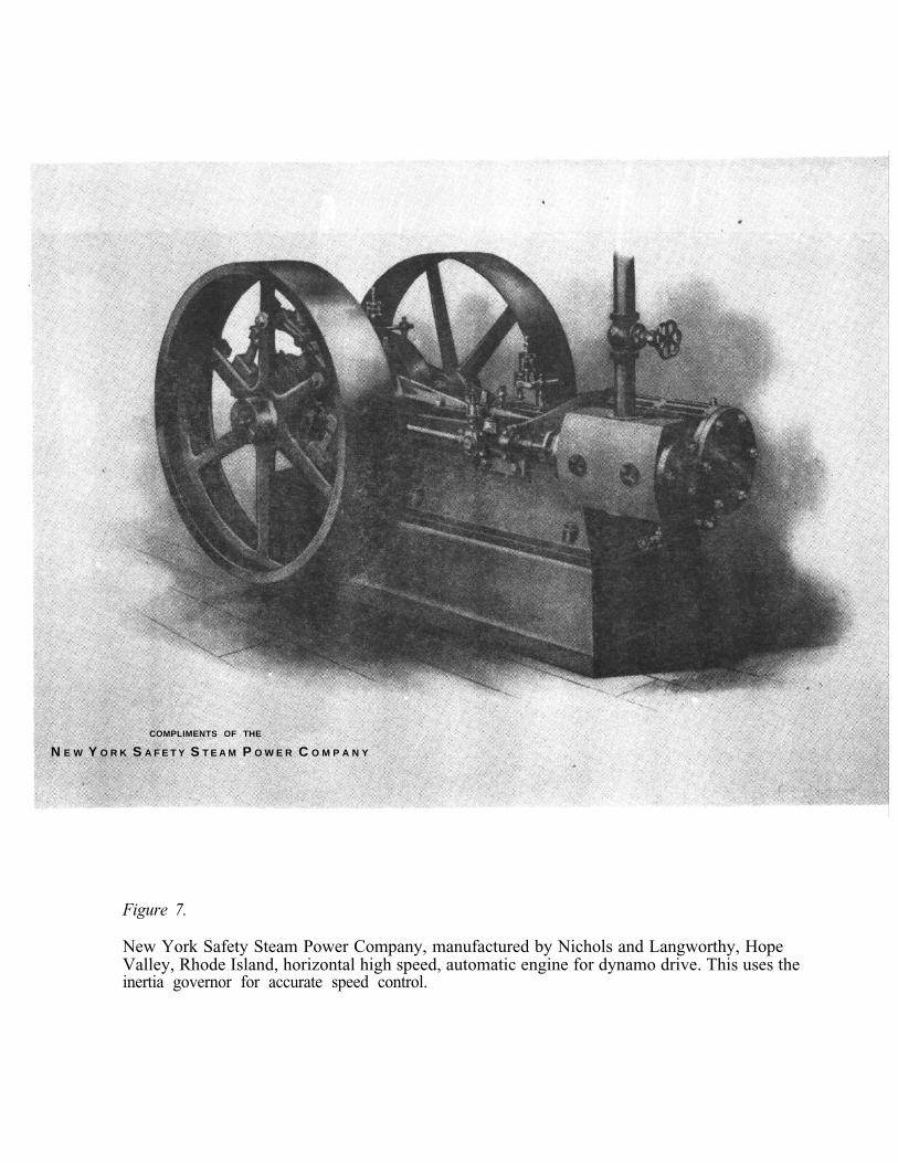
This is a horizontal, piston valve, automatic cut-off engine showing strong influence ofthe Armington & Sims (See Fig. 7).
Herreshoff Manufacturing Co., (1904) Bristol, Rhode Island
This is a 385 horsepower, triple expansion engine originally designed for torpedo boatuse. It exhibits many ingenious techniques to reduce weight and size; for example the splitconnecting rods and the side mounted valves. In the triple expansion engine thermal loss isreduced by expanding the steam in three stages from boiler pressure to condenser pressure. Thetotal temperature drop is divided into three parts so that the temperature difference across anycylinder is one third that of a single cylinder engine. Heat loss is correspondingly reduced.Triple expansion engines often operated with superheated steam, further improving efficiency.
The engine on display was used for 80 years at the Phelps Dodge copper refinery inMaspeth, Long Island, New York. It along with three others drove low voltage DC generatorsto supply current to the electrolytic refining cells. The cylinders are pressure lubricated but the

connecting rods and crankshaft are splash lubricated. For display purposes the crankshaft isopen. Normally it would be closed, much as a modern automobile engine.
Herreshoff Manufacturing Co., Bristol, Rhode Island (c 1905)
This engine is similar in principle to the triple except only two stages of expansion areused. The engine is simpler than the triple while still being a good performer. The compoundwas the preferred engine for tug boats, small yachts, small excursions steamers and fishingboats.
Herreshoff Manufacturing Co., Bristol, Rhode Island (c 1900)
This small vertical, splendidly built, bronze single cylinder, non reversing engine wasprobably used to drive a pump. The bronze construction was characteristic of Captain NathanielHerreshoff.
Granger Foundry and Machine Co., Providence, R.I. (c 1880)
This unusual two cylinder, inverted VEE, simple, slide valve engine was designed todrive textile printing machinery. The arrangement allowed direct connection to the load and the90 degree positioning of the cylinders resulting in positive starting.
American Engine Co., Bound Brook, New Jersey (c 1905)
The American Ball Engine is a later version of the Armington & Sims automatic cut-offengine with flywheel-mounted Rites inertia governor. This engine is designed to run at 240RPM driving a 30 pole, 100 kw three phase General Electric alternator (see Fig. 8).
Eddy Co., Windsor Locks, Connecticut (c 1890)
This unusual triple expansion engine was designed and built to power a racing boat tocompete in the Vanderbilt Cup Races held in the nineties on the Connecticut River. A coil boilerdesigned for 1,000 psi supplied the steam. For strength reasons and also for compactness thehigh pressure cylinder is surrounded by the intermediate pressure cylinder which assume theform of an annulus. In a quick glance this engine looks like a compound but in fact it is a triple.The three pistons are coupled to the crankshaft by scotch yokes.

Maj
or E
ngin
es i
n th
e C
olle
ctio
n of
the
New
Eng
land
Mus
eum
of W
irel
ess
and
Stea
m
Stea
m
Cyl
inde
rSp
eed
Pow
erPr
essu
reSo
urce
Bui
lder
Dat
eT
ype
Arr
ange
men
tD
imen
sion
s*(R
PM)
(BH
P)(p
sig)
Cor
liss
Stea
m18
924
valv
eH
oriz
onta
lB
: 16
"80
100
Stra
tton
Co.
,E
ngin
e C
o.,
Mill
S:
42
"St
ratto
n, M
E,
c 19
78,
Prov
iden
ce,
RI
Will
iam
A. H
arri
s18
92C
orlis
s ty
peH
oriz
onta
lB
: 15
"10
0Po
nd L
ily C
o.,
Stea
m E
ngin
e C
o.,
Mill
S:
42
"W
estv
ille,
CT
, c.
197
7.Pr
ovid
ence
, R
ID
onat
ed b
y Ev
elyn
Mou
lton
Will
iam
A. H
arri
sc1
911
Cor
liss
type
Hor
izon
tal
B:
16"
150
150
Nat
iona
l L
aund
ry C
o.,
Mill
S:
30
:D
orch
este
r, M
A,
1969
Bax
ter
c186
8Sl
ide
valv
eV
ertic
al,
B:
7"10
80Fa
xon
Co.
,M
anuf
actu
ring
Co.
cylin
der
inS:
8"
Qui
ncy,
MA
.bo
iler
Am
eric
an E
ngin
ec1
905
Pist
on v
alve
Hor
izon
tal
B:
14"
150
125
150
Nat
iona
l L
aund
ry C
o.,
Co.
, B
ound
Bro
ok,
Dir
ect
S:
12
"D
orch
este
r, M
A,
1969
NJ
(Am
eric
an B
all
Con
nect
eden
gine
)A
ltern
ator
Her
resc
hoff
1904
Tri
ple
Ver
tical
,B
: 10
"30
038
520
0Ph
elps
Dod
ge C
o.,
Man
ufac
turin
g C
o.ex
pans
ion
mar
ine
type
15"
Bro
okly
n, N
Ypi
ston
va
lves
20
"S
: 1
4"
Fitc
hbur
g St
eam
c190
5pi
ston
va
lve
Hor
izon
tal
B: 1
4 1/
2"15
013
0N
oone
M
ill,
Eng
ine
Co.
,M
illS:
28"
Pete
rbor
o, N
H,
date
Fitc
hbur
g,
MA
unkn
own.
Trip
le
expa
n-M
. E
ddy,
Win
dsor
c189
0si
on I
P cy
lin-
Ver
tical
100
1000
?L
ocks
, C
Tde
r co
ncen
tric
Mar
ine
to H
P cy
linde
r
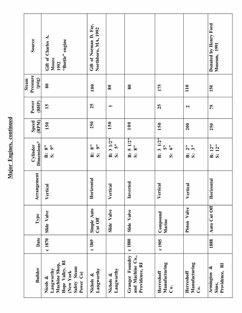
Maj
or E
ngin
es,
cont
inue
d
Stea
m
Cyl
inde
rSp
eed
Pow
erP
ress
ure
Sour
ceB
uild
erD
ate
Typ
eA
rran
gem
ent
Dim
ensi
ons*
(RP
M)
(BH
P)(p
sig)
Nic
ols
&c
1870
Slid
e V
alve
Ver
tica
lB
: 8"
150
1580
Gift
of
Cha
rles
A.
Lan
gwor
thy
S:
9"M
oore
Mac
hine
Sho
p,19
92H
ope
Val
ley,
RI
“Bot
tle”
eng
ine
(New
Yor
kSa
fety
St
eam
Pow
er C
o)
Nic
hols
&c
1869
Sim
ple
Aut
oL
angw
orth
yC
ut O
ff
Nic
hols
&Sl
ide
Val
veL
angw
orth
y
Gra
nger
F
ound
ryc
1880
Slid
e V
alve
and
Mac
hine
Co.
,P
rovi
denc
e, R
I
Hor
izon
tal
Ver
tica
l
Inve
rted
B:
8"25
025
100
Gift
of
Nor
man
D.
Fay,
S:
9"N
orth
boro
, MA
, 199
2
B:
3 1/
2"1
50
580
S:
5"
B:
5 1/
2"1
00
80S
: 8"
Her
resh
off
Man
ufac
turi
ngC
o.
c 19
05C
ompo
und
Mar
ine
Ver
tica
lB
: 3
1/2"
15
025
175
5"S:
6"
Her
resh
off
Man
ufac
turi
ngC
o.
Pist
on
Val
veV
erti
cal
B:
2"20
02
110
S:
3"
Arm
ingt
on
&Si
ms,
Prov
iden
ce,
RI
1888
Aut
o C
ut O
ffH
oriz
onta
lB
: 12
"S:
12"
250
7515
0D
onat
ed b
y H
enry
For
dM
useu
m,
1991

THE NEW ENGLAND WIRELESS & STEAM MUSEUM
The museum began in 1964 with a collection of early wireless and radio equipmentbrought together by Robert W. and Nancy A. Merriam. A formal but private organization wasestablished when a group of interesting historians and important early radio design engineersopened a 35 x 65 foot building to house the collection.
The quality and scope of the collection improved rapidly when several private collectionsof senior engineers were given to the museum. From the beginning Nancy Merriam, who hasserved as librarian, appreciated the importance of preserving documents and as a consequence themuseum has an outstanding reference library of mechanical and electrical engineering history.
In 1966 the museum was incorporated as the New England Wireless & Steam Museumwith R.W. Merriam as its Director and with a distinguished board consisting largely of engineersand businessmen. Merriam’s interest in steam developed naturally, being a native RhodeIslander and being the son of Paul Merriam who taught steam engineering as Lionel S. Mark’sassistant at the Harvard Engineering School 1910-1912.
In 1966 the museum’s board decided to include stationary steam engines, with a specialemphasis on Rhode Island built engines, to insure that this record be preserved. In 1972 aa 40 by 80 foot building was erected entirely by volunteers to house the growing collectionof large steam engines. Every engine in the steam building was a donation. Some have comefrom great distances and all had to be rigged, shipped and re-erected with the effort ofvolunteers. Each of these exercises brought to light long forgotten facts. Today, with theengines connected to boilers, many can appreciate the great work that was done in Rhode Islandmore than 100 years ago when its engines were shipped all over the world.
Also in 1972 an 1822 New England meeting house was saved from the wrecker andmoved to the museum. This building is now on the National Register. It is used for engineeringsociety meeting, seminars, club meetings, and even weddings. The lower floor houses theelectrical engineering reference library.
In 1982 the museum received a remarkable gift in the form of the complete 2 1/2 storycoastal Massie Wireless Telegraph Company station from Point Judith, R.I. This is one of theoldest surviving wireless stations in the world and it has been very little altered since being builtin 1907 It is complete with all its original wireless telegraph equipment. It also houses the ArthurC. Goodnow collection of spark transmitters.
Currently the museum is completing work on the Mayes building named for formerdirector, Thorn L. Mayes, a registered PE in both mechanical and electrical engineering and agenerous benefactor of this museum. The Mayes building will house the mechanical engineeringreference library and the collection of small antique steam engines, models and the extensivecollection of engineering drawings which came from former steam engine manufacturers inRhode Island. It will also be the location of the museum’s office.
The museum is a public IRS (501C) corporation and all contributions to it are tax exempt.The museum has no paid staff. From the beginning it has strictly adhered to a policy neither toseek government grants nor to accept them. It is funded entirely by private gifts, grants fromprivate foundations, by admissions, and by the sale of publications and other items. Its purposeis to preserve engineering history, the record of great innovators and business creators to showthe immense value to society of their work.
PLAQUE
NATIONAL MECHANICAL ENGINEERING HERITAGE COLLECTIONTHE NEW ENGLAND WIRELESS AND STEAM MUSEUM
By the middle of the nineteenth century American industry - especially in New England -was rapidly outgrowing the capacity of the water power that had been its principal prime mover.The need for a new power source inspired an intense development of the steam engine, the workof inventors directed mainly at improving fuel efficiency by reducing steam consumption. Theleader in this effort was George H. Corliss, whose improvements in efficiency and mechanicaldetail earned him the title “The American James Watt.”
By the 1870’s Corliss’ Providence Engine Works was the world’s largest and drew tothe state a number of other important builders, Rhode Island becoming the steam-engine capitalof the nation.
This museum contains the finest collection of Rhode Island engines, including one of thethree built at the Corliss Works known to survive.
THE AMERICAN SOCIETY OF MECHANICAL ENGINEERS - 1992
ACKNOWLEDGEMENTS
This brochure was prepared by Robert W. Merriam, Nancy Merriam, Anthony J. Rafanelli, andEuan F. C. Somerscales.
FURTHER READING
1. Thurston, R.H., A History of the Growth of the Steam-Engine,Centennial Edition with a supplementary chapter by William M. Barnard. Ithaca, NY:Cornell University Press, 1939.(This book is available in several editions, beginning with that originally published byThurston in 1878.)
Hunter, L.C., A History of Industrial Power in the United States 1780-1930.Volume Two: Steam Power. Charlottesville, VA:University Press of Virginia for the Hagley Museum and LIbrary, 1985.
Hills, R.L., Power from Steam: A History of the Stationary Steam Engine. Cambridge:Cambridge University Press, 1989.
2.
3.
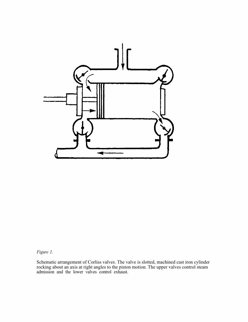
Figure 1.
Schematic arrangement of Corliss valves. The valve is slotted, machined cast iron cylinderrocking about an axis at right angles to the piston motion. The upper valves control steamadmission and the lower valves control exhaust.

Figure 2.
Corliss engine manufactured by the Corliss Steam Engine Company, Providence, Rhode Island,in 1892. The unique spider form of wrist plate should be noted.

Figure 3.
Harris Corliss engine showing Corliss valve gear. The circular disc wrist plate is centrallylocated on the side of the cylinder. It is driven by a rod which extends to the eccentric on thecrank shaft. The ends of the four valves protrude from the four corners of the cylinder casing.The upper valves control the steam admission and the lower valves control its exhaust. Thedashpots are on the floor at the front and rear of the cylinder. Vertical rods tie them to theadmission valves. Rods connect the governor to the admission valves to control the time ofsteam cut-off.
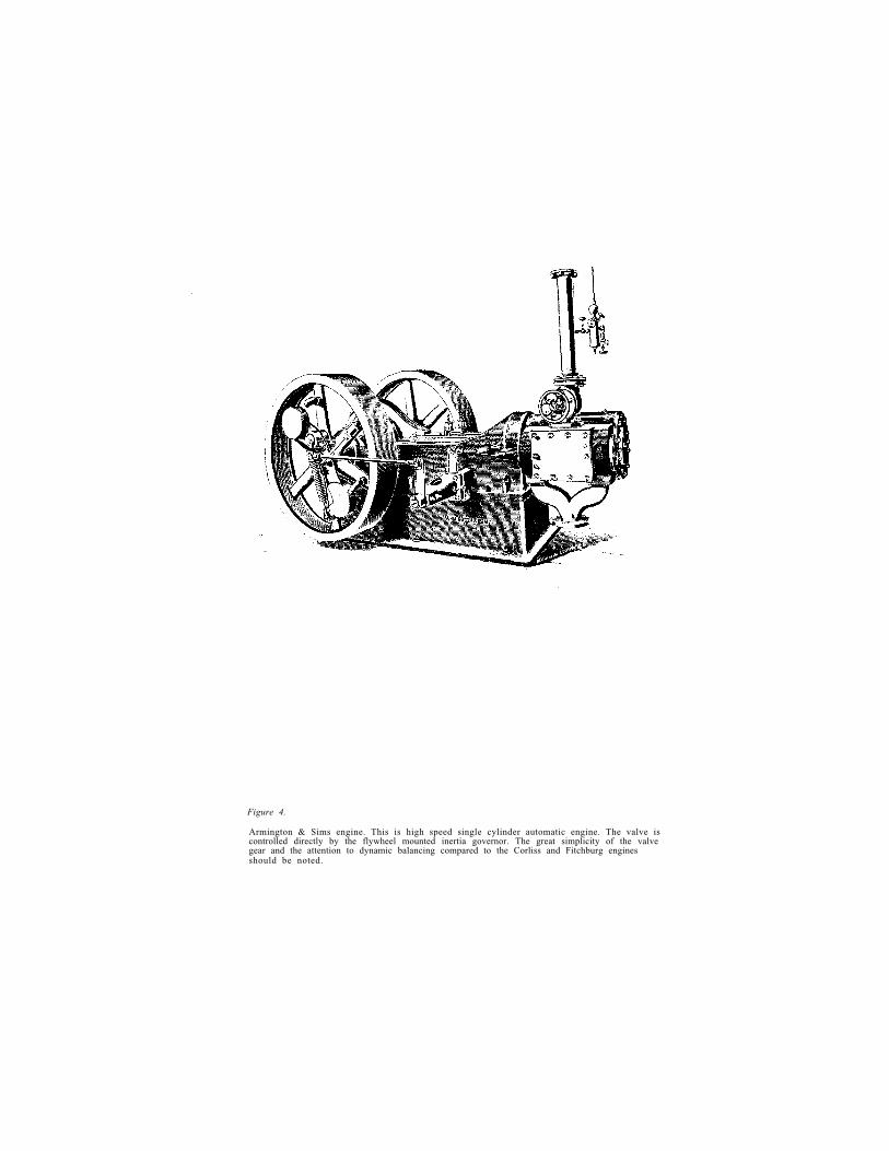
Figure 4.
Armington & Sims engine. This is high speed single cylinder automatic engine. The valve iscontrolled directly by the flywheel mounted inertia governor. The great simplicity of the valvegear and the attention to dynamic balancing compared to the Corliss and Fitchburg enginesshould be noted.

Figure 5.
Fitchburg engine. This is a girder frame engine. Note the double rods that connect the valvegear to the valve eccentrics which are mounted on the main shaft behind the flywheel andgovernor.
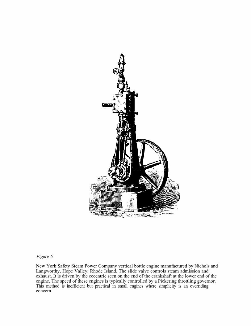
Figure 6.
New York Safety Steam Power Company vertical bottle engine manufactured by Nichols andLangworthy, Hope Valley, Rhode Island. The slide valve controls steam admission andexhaust. It is driven by the eccentric seen on the end of the crankshaft at the lower end of theengine. The speed of these engines is typically controlled by a Pickering throttling governor.This method is inefficient but practical in small engines where simplicity is an overridingconcern.
COMPLIMENTS OF THE
N E W Y O R K S A F E T Y S T E A M P O W E R C O M P A N Y
Figure 7.
New York Safety Steam Power Company, manufactured by Nichols and Langworthy, HopeValley, Rhode Island, horizontal high speed, automatic engine for dynamo drive. This uses theinertia governor for accurate speed control.

THE FAMOUS AMERICAN-BALL SIMPLE ENGINE—GOVERNOR SIDE
Figure 8.
The American Ball engine, built in Bound Brook, New Jersey, is a later version of the highspeed, automatic engine designed for direct alternator drive.

T H E N E W E N G L A N D W I R E L E S S & S T E A M M U S E U MF R E N C H T O W N R O A D E A S T G R E E N W I C H . H I . 0 2 8 1 8
STEAM BUILDING EQUIPMENT LAYOUT
1. 5 hp Vertical Fire Tube Boiler. Built in 19502. 20 HP Dry Back Scotch Boiler. Built in 19763. 150 hp Horizontal Engine. Built circa 19004. 150 hp High Speed Engine, Direct Electric Dynamo Drive. Built circa 19005. 10 hp Baxter Engine/Boiler. Built circa 18686. 150 hp Harris Engine. Heavy duty Frame. Built in.19117. 25 hp Automatic cut off Engine. Built in 1892 for R.I. State College8. 75 hp Automatic Cut Off Horizontal Engine. Built in 18889. 5 hp Horizontal Side Crank Engine. Built circa 189010. 15 hp Riding Cut Portable Farm Engine. Built circa 187011. 20 hp Horizontal Engine. Built circa 187012. 5 HP Vertical Bottle Engine. Built circa 186913. 25 hp, 2 Cylinder, Textile Printing Machine Engine. Built circa 187014. Hydraulic Turbine Governor. Built in 190415. 150 hp Girder Frame Horizontal Mill Engine. Built in 189216. Horizontal Mill Engine, Designed circa 1887, Built in 189217. Boiler Face from Bay Mill East Greenwich. Built circa 190018. 25 hp Enclosed Vertical Engine. Built about 1920 for BP119. 385 hp Triple Expansion Vertical Engine. Built 190420. Noiseless Right Angle Drive. Built 188421. 15 hp Vertical Bottle Engine22. 15 hp Engine with Riding Cut Off. Built circa 188523. 25 hp Coal Stoker Engine. Built circa 191024. Sears Roebuck Engine. Built circa 189925. 2 hp Bipolar DC Generator. Built in 189126. Overhead Line Shafting27. Hot Air Doaestic Water Pumping. Enqine. Built Circa 1890
DIRECTORS OF NEW ENGLAND WIRELESS & STEAM MUSEUM
September 12, 1992
Robert W. MerriamWlNTE
Nancy A. Merriam
Richard B. Hanson
Merrill P. BudlongWlMB
Patrick Malone
Gerald Weinstein
George King III
Walter P. Fay
Rodger B. Dowdell
Harvard Engineering School, M.S., PEPresident, Merriam Instruments, Inc.East Greenwich, RI
R.I. School of Design, B.F.A.Secretary Merriam Instruments, Inc.East Greenwich, RI
Wentworth InstituteDistrict Superintendent,Transmission & DistributionNarragansett Electric Co., Providence, RI
University of Rhode Island, B.S.RetiredEdgewood, RI
U.S. Naval Academy, B.S.Brown University, Ph.D.Senior Lecturer, Brown UniversityProvidence, RI
Wilmington College, B.A.Chairman, General Tools Mfg. Co.,New York NY
USCG (retired)Licensed Marine Steam EngineerNorth Franklin, CT
Boston UniversityRetiredSouth Dartmouth, MA
Brown University, B.S.,U.R.I., M.S.,CEO American Power ConversionWest Kingstown, RI

THE AMERICAN SOCIETY OF MECHANICAL ENGINEERS
Joseph A. Falcon, PresidentDavid L. Belden, Executive DirectorThomas Doherty, Vice President, Region IDonald Kitchin, History & Heritage Chairperson, Region IHarold Keirnan, Director, Northeast Regional Office
AMERICAN SOCIETY OF MECHANICAL ENGINEERSNATIONAL HISTORY AND HERITAGE COMMITTEE
Dr. Euan EC. Sommerscales, Chairperson Joseph P. Van Overveen, P.E.Robert M. Vogel, Secretary John H. LienhardDr. Robert B. Gaither J.L. Lee, P.E.Dr. Richard S. Hartenberg, P. E. R. Carson Dalzell, PE., Chairman EmeritusDr. J. Paul Hartman, P.E. Carron Garvin-Donahue, Staff Liason
THE AMERICAN SOCIETY OF MECHANICAL ENGINEERSPROVIDENCE SECTION
Joseph Nunes, ChairpersonJoseph Borgia, Vice-ChairBijan Kheradi, SecretaryNino Granatiero, TreasurerPatricia Hixson, Past Chair
THE DEDICATION COMMITTEE
Bruce WilcoxAnthony J. Rafanelli, P.E.Robert W. Merriam, P.E.Joseph NunesJoseph Borgia
H164