stereo minidisc recorder dmf-5020 dmf-3020 … · stereo minidisc recorder b60-4074-00 01 ma...
TRANSCRIPT
STEREO MINIDISC RECORDER
B60-4074-00 01 MA (K,P,T) MC 9806
DMF-5020DMF-3020MD-203INSTRUCTION MANUAL
This instruction manual is used to describe multiple models listed above.
Model availability and features (functions) may differ depending on the country and sales
area.
DMF-5020/DMF3020/MD-203 (En)
2
RISK OF ELECTRIC SHOCKDO NOT OPEN
CAUTION
Introduction
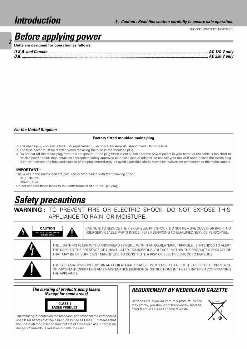
Before applying power
The marking is located on the rear panel and says that the componentuses laser beams that have been classified as Class 1. It means thatthe unit is utilizing laser beams that are of a weaker class. There is nodanger of hazardous radiation outside the unit.
CLASS 1LASER PRODUCT
The marking of products using lasers(Except for some areas)
WARNING : TO PREVENT FIRE OR ELECTRIC SHOCK, DO NOT EXPOSE THISAPPLIANCE TO RAIN OR MOISTURE.
Safety precautions
Factory fitted moulded mains plug
1. The mains plug contains a fuse. For replacement, use only a 13- Amp ASTA-approved (BS1362) fuse.2. The fuse cover must be refitted when replacing the fuse in the moulded plug.3. Do not cut off the mains plug from this equipment. If the plug fitted is not suitable for the power points in your home or the cable is too short to
reach a power point, then obtain an appropriate safety approved extension lead or adapter, or consult your dealer.If nonetheless the mains plugis cut off, remove the fuse and dispose of the plug immediately, to avoid a possible shock hazard by inadvertent connection to the mains supply.
IMPORTANT :The wires in the mains lead are coloured in accordance with the following code :
Blue: NeutralBrown : Live
Do not connect those leads to the earth terminal of a three - pin plug.
For the United Kingdom
CAUTION: TO REDUCE THE RISK OF ELECTRIC SHOCK, DO NOT REMOVE COVER (OR BACK). NOUSER-SERVICEABLE PARTS INSIDE, REFER SERVICING TO QUALIFIED SERVICE PERSONNEL.
THE LIGHTNING FLASH WITH ARROWHEAD SYMBOL, WITHIN AN EQUILATERAL TRIANGLE, IS INTENDED TO ALERTTHE USER TO THE PRESENCE OF UNINSULATED “DANGEROUS VOLTAGE” WITHIN THE PRODUCT’S ENCLOSURETHAT MAY BE OF SUFFICIENT MAGNITUDE TO CONSTITUTE A RISK OF ELECTRIC SHOCK TO PERSONS.
THE EXCLAMATION POINT WITHIN AN EQUILATERAL TRIANGLE IS INTENDED TO ALERT THE USER TO THE PRESENCEOF IMPORTANT OPERATING AND MAINTENANCE (SERVICING) INSTRUCTIONS IN THE LITERATURE ACCOMPANYINGTHE APPLIANCE.
Caution : Read this section carefully to ensure safe operation.
Units are designed for operation as follows.
U.S.A. and Canada ................................................................................................................................................................ AC 120 V onlyU.K. ........................................................................................................................................................................................... AC 230 V only
REQUIREMENT BY NEDERLAND GAZETTE
Batteries are supplied with this product. Whenthey empty, you should not throw away. Instead,hand them in as small chemical waste.
DMF-5020/DMF3020/MD-203 (En)
3
Introduction .......................................................................................................................................... 2
Before applying power ..................................................................................................................... 2Safety precautions ............................................................................................................................ 2Contents ........................................................................................................................................... 3Accessories ...................................................................................................................................... 4Special feature .................................................................................................................................. 5
IMPORTANT SAFEGUARDS ............................................................................................................... 6
Information that you should know .................................................................................................... 8
Safety Precautions ............................................................................................................................ 8Maintenance ..................................................................................................................................... 9
System connections .......................................................................................................................... 10
Names and functions of parts .......................................................................................................... 12
Display/Main unit ............................................................................................................................ 12Remote control unit (DMF-5020) .................................................................................................... 14Remote control unit (DMF-3020/MD-203) ..................................................................................... 15
Operation of remote control unit..................................................................................................... 16
Playback of Mini Disc ........................................................................................................................ 17
Playing tracks in order from track No. 1 ......................................................................................... 17Searching a desired track by its title (TITLE SEARCH) ................................................................... 18Playback from desired track ........................................................................................................... 19Random playback ........................................................................................................................... 19
Programming ..................................................................................................................................... 21
Programming tracks in a desired order .......................................................................................... 21Repeated playback ......................................................................................................................... 23
Recording-related keys ..................................................................................................................... 24
AUTO/MANU. key .......................................................................................................................... 24MONITOR key ................................................................................................................................ 24REC MODE key .............................................................................................................................. 24Automatically starting recording when the track starts (SOUND SYNCHRO REC) ....................... 26Automatically pausing recording when the track ends (REC AUTO PAUSE)................................. 26Starting recording from the sound before the current sound (MEMORY REC) ............................ 26
Recording (ANALOG input) .............................................................................................................. 27
ANALOG recording ......................................................................................................................... 27Recording (DIGITAL input) ................................................................................................................ 29
DIGITAL recording .......................................................................................................................... 29Synchro recording with CD playback.............................................................................................. 31DIGITAL recording and SCMS ........................................................................................................ 31
Editing ................................................................................................................................................. 32
Selecting the editing function type................................................................................................. 32Moving the track being played (TRACK MOVE) ............................................................................. 33Moving several tracks at a time (QUICK MOVE) ............................................................................ 35Dividing the track being played (TRACK DIVIDE) ........................................................................... 37Combining the track being played (TRACK COMBINE) ................................................................. 39Erasing the track being played (TRACK ERASE) ............................................................................ 41Erasing one or more track at a time (QUICK ERASE) .................................................................... 43Editing titles .................................................................................................................................... 45
Changing the displayed contents .................................................................................................... 49
TIME DISPLAY key ......................................................................................................................... 49METER key ..................................................................................................................................... 49
Timer operations ............................................................................................................................... 50
Timer playback, timer recording ..................................................................................................... 50In case of difficulty ............................................................................................................................ 51
Specifications ..................................................................................................................................... 54
Contents
Introduction
Caution : Read the pages marked carefully to ensure safe operation.
DMF-5020/DMF3020/MD-203 (En)
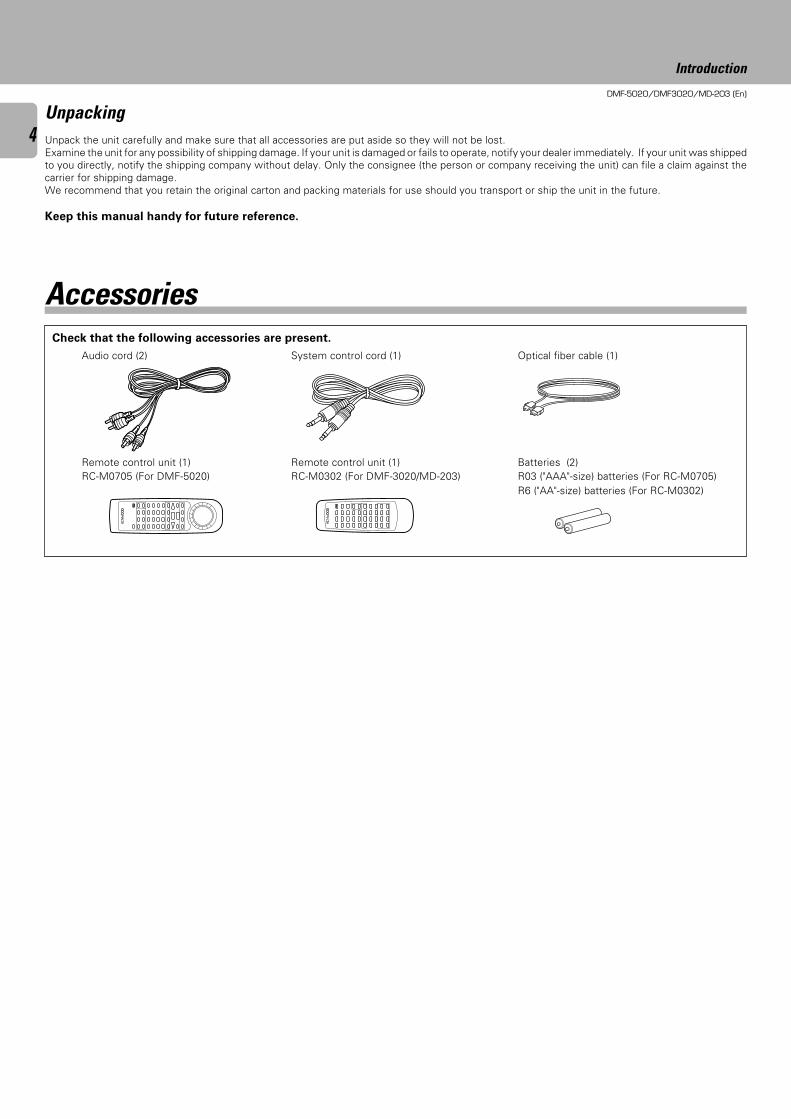
4UnpackingUnpack the unit carefully and make sure that all accessories are put aside so they will not be lost.Examine the unit for any possibility of shipping damage. If your unit is damaged or fails to operate, notify your dealer immediately. If your unit was shippedto you directly, notify the shipping company without delay. Only the consignee (the person or company receiving the unit) can file a claim against thecarrier for shipping damage.We recommend that you retain the original carton and packing materials for use should you transport or ship the unit in the future.
Keep this manual handy for future reference.
Remote control unit (1)RC-M0705 (For DMF-5020)
Batteries (2)R03 ("AAA"-size) batteries (For RC-M0705)R6 ("AA"-size) batteries (For RC-M0302)
Check that the following accessories are present.
Audio cord (2) System control cord (1) Optical fiber cable (1)
Accessories
Introduction
Remote control unit (1)RC-M0302 (For DMF-3020/MD-203)
DMF-5020/DMF3020/MD-203 (En)
5
This unit is audio equipment based on the Mini Disc format. The Mini Disc (MD) is an application of the optical and magneto-optical technology andhas the capability to record signals on discs.The operability of the MD is equivalent to the Compact Disc (CD). The MD uses optional non-contactsystem so the recordings are not degraded by eternal factors and the discs are never scratched or damaged in playback.
Special feature
Sampling rate converter
The DMF-5020 is equipped with KENWOOD-original “24-bit D/A
D.R.I.V.E.II”, providing high quality playback.
(D.R.I.V.E.:Dynamic Resolution Intensive Vector Enhancement)
The sampling rate converter incorporated in this unit is compatible
with all digital sources (32 kHz, 44.1 kHz, 48 kHz).
÷48 kHz : Standard mode of DAT. For recording of B mode broadcasting of BStuner, etc.
÷44.1 kHz: Standard mode of DAT. For recording of CD, MD, etc.÷32 kHz : Standard mode and long-hour mode of DAT. For recording of A mode
broadcasting of BS tuner.
In addition to the conventional editing functions (MOVE, DIVIDE,
COMBINE and ERASE), this unit provides more versatile editing
functions such as the QUICK MOVE function for moving desired tracks
at once or the QUICK ERASE function for erasing desired tracks at
once.
“D.R.I.V.E.” for high-quality playback(For DMF-5020 only)
Versatile editing functions
Title input, title search
This unit is equipped with the “SOUND SYNCHRO REC” and “AUTO
CUT” functions for automatically starting and pausing recording
simultaneously with the sound input, the “REC AUTO PAUSE” func-
tion for automatically stopping recording when the end of one track
on the CD is reached, and the “MEMORY REC” function for starting
recording from approximately 6 seconds before the current sound.
In addition to the “Title input function” which allows to assign disc
and track titles simply using the multi-jog dial and the “Title search
function” which allows to find the desired track title, the “Preset title
function” provides a selection of frequently used titles.
SOUND SYNCHRO REC functions
Introduction
DMF-5020/DMF3020/MD-203 (En)
6
IMPORTANT SAFEGUARDS
Please read all of the safety and operating instructions beforeoperating this appliance. Adhere to all warnings on the applianceand in the instruction manual. Follow all the safety and operatinginstructions. These safety and operating instructions should beretained for future reference.
1. Power sources – The appliance should be connected to apower supply only of the type described in the instructionmanual or as marked on the appliance. If you are not sure ofthe type of power supply to your home, consult your appliancedealer or local power company. For appliances intended tooperate from battery power, or other sources, refer to theinstruction manual.
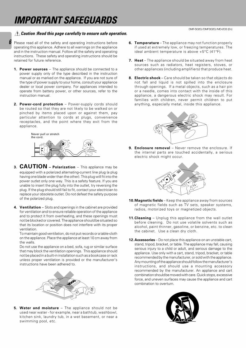
2. Power-cord protection – Power-supply cords shouldbe routed so that they are not likely to be walked on orpinched by items placed upon or against them, payparticular attention to cords at plugs, conveniencereceptacles, and the point where they exit from theappliance.
3. CAUTION – Polarization – This appliance may beequipped with a polarized alternating-current line plug (a plughaving one blade wider than the other). This plug will fit into thepower outlet only one way. This is a safety feature. If you areunable to insert the plug fully into the outlet, try reversing theplug. If the plug should still fail to fit, contact your electrician toreplace your obsolete outlet. Do not defeat the safety purposeof the polarized plug.
4. Ventilation – Slots and openings in the cabinet are providedfor ventilation and to ensure reliable operation of the applianceand to protect it from overheating, and these openings mustnot be blocked or covered. The appliance should be situated sothat its location or position does not interfere with its properventilation.To maintain good ventilation, do not put records or a table-clothon the appliance. Place the appliance at least 10 cm away fromthe walls.Do not use the appliance on a bed, sofa, rug or similar surfacethat may block the ventilation openings. This appliance shouldnot be placed in a built-in installation such as a bookcase or rackunless proper ventilation is provided or the manufacturer’sinstructions have been adhered to.
5. Water and moisture – The appliance should not beused near water - for example, near a bathtub, washbowl,kitchen sink, laundry tub, in a wet basement, or near aswimming pool, etc.
Never pull or stretchthe cord.
6. Temperature – The appliance may not function properlyif used at extremely low, or freezing temperatures. Theideal ambient temperature is above +5°C (41°F).
7. Heat – The appliance should be situated away from heatsources such as radiators, heat registers, stoves, orother appliances (including amplifiers) that produce heat.
8. Electric shock – Care should be taken so that objects donot fall and liquid is not spilled into the enclosurethrough openings. If a metal objects, such as a hair pinor a needle, comes into contact with the inside of thisappliance, a dangerous electric shock may result. Forfamilies with children, never permit children to putanything, especially metal, inside this appliance.
9. Enclosure removal – Never remove the enclosure. Ifthe internal parts are touched accidentally, a seriouselectric shock might occur.
10.Magnetic fields – Keep the appliance away from sourcesof magnetic fields such as TV sets, speaker systems,radios, motorized toys or magnetized objects.
11.Cleaning – Unplug this appliance from the wall outletbefore cleaning. Do not use volatile solvents such asalcohol, paint thinner, gasoline, or benzine, etc. to cleanthe cabinet. Use a clean dry cloth.
12.Accessories – Do not place this appliance on an unstable cart,stand, tripod, bracket, or table. The appliance may fall, causingserious injury to a child or adult, and serious damage to theappliance. Use only with a cart, stand, tripod, bracket, or tablerecommended by the manufacturer, or sold with the appliance.Any mounting of the appliance should follow the manufacturer’sinstructions, and should use a mounting accessoryrecommended by the manufacturer. An appliance and cartcombination should be moved with care. Quick stops, excessiveforce, and uneven surfaces may cause the appliance and cartcombination to overturn.
Caution :Read this page carefully to ensure safe operation.
DMF-5020/DMF3020/MD-203 (En)
713.Lightning – For added protection for this appliance during a
lightning storm, or when it is left unattended and unused forlong periods of time, unplug it from the wall outlet anddisconnect the antenna or cable system. This will preventdamage to the appliance due to lightning and power-linesurges.
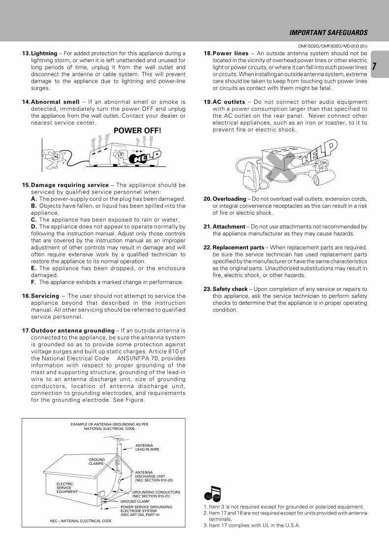
14.Abnormal smell – If an abnormal smell or smoke isdetected, immediately turn the power OFF and unplugthe appliance from the wall outlet. Contact your dealer ornearest service center.
15.Damage requiring service – The appliance should beserviced by qualified service personnel when:A. The power-supply cord or the plug has been damaged.B. Objects have fallen, or liquid has been spilled into theappliance.C. The appliance has been exposed to rain or water.D. The appliance does not appear to operate normally byfollowing the instruction manual. Adjust only those controlsthat are covered by the instruction manual as an improperadjustment of other controls may result in damage and willoften require extensive work by a qualified technician torestore the appliance to its normal operation.E. The appliance has been dropped, or the enclosuredamaged.F. The appliance exhibits a marked change in performance.
16.Servicing – The user should not attempt to service theappliance beyond that described in the instructionmanual. All other servicing should be referred to qualifiedservice personnel.
17.Outdoor antenna grounding – If an outside antenna isconnected to the appliance, be sure the antenna systemis grounded so as to provide some protection againstvoltage surges and built up static charges. Article 810 ofthe National Electrical Code ANSI/NFPA 70, providesinformation with respect to proper grounding of themast and supporting structure, grounding of the lead-inwire to an antenna discharge unit, size of groundingconductors, locat ion of antenna discharge unit ,connection to grounding electrodes, and requirementsfor the grounding electrode. See Figure.
18.Power lines – An outside antenna system should not belocated in the vicinity of overhead power lines or other electriclight or power circuits, or where it can fall into such power linesor circuits. When installing an outside antenna system, extremecare should be taken to keep from touching such power linesor circuits as contact with them might be fatal.
19.AC outlets – Do not connect other audio equipmentwith a power consumption larger than that specified tothe AC outlet on the rear panel. Never connect otherelectrical appliances, such as an iron or toaster, to it toprevent fire or electric shock.
20. Overloading – Do not overload wall outlets, extension cords,or integral convenience receptacles as this can result in a riskof fire or electric shock.
21. Attachment – Do not use attachments not recommended bythe appliance manufacturer as they may cause hazards.
22. Replacement parts – When replacement parts are required,be sure the service technician has used replacement partsspecified by the manufacturer or have the same characteristicsas the original parts. Unauthorized substitutions may result infire, electric shock, or other hazards.
23. Safety check – Upon completion of any service or repairs tothis appliance, ask the service technician to perform safetychecks to determine that the appliance is in proper operatingcondition.
EXAMPLE OF ANTENNA GROUNDING AS PER
NATIONAL ELECTRICAL CODE
ANTENNADISCHARGE UNIT(NEC SECTION 810-20)
POWER SERVICE GROUNDINGELECTRODE SYSTEM(NEC ART 250, PART H)
GROUND CLAMP
ANTENNALEAD IN WIRE
GROUNDCLAMPS
NEC – NATIONAL ELECTRICAL CODE
GROUNDING CONDUCTORS(NEC SECTION 810-21)
1. Item 3 is not required except for grounded or polarized equipment.2. Item 17 and 18 are not required except for units provided with antenna
terminals.3. Item 17 complies with UL in the U.S.A.
POWER OFF!
IMPORTANT SAFEGUARDS
ELECTRICSERVICEEQUIPMENT
NotesNotes
DMF-5020/DMF3020/MD-203 (En)
8Safety Precautions
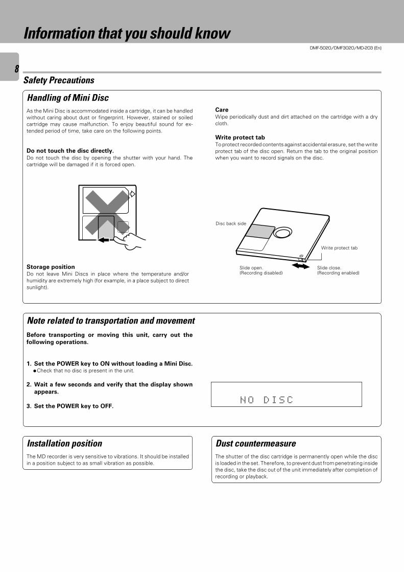
Do not touch the disc directly.Do not touch the disc by opening the shutter with your hand. Thecartridge will be damaged if it is forced open.
Handling of Mini DiscAs the Mini Disc is accommodated inside a cartridge, it can be handledwithout caring about dust or fingerprint. However, stained or soiledcartridge may cause malfunction. To enjoy beautiful sound for ex-tended period of time, take care on the following points.
CareWipe periodically dust and dirt attached on the cartridge with a drycloth.
Write protect tabTo protect recorded contents against accidental erasure, set the writeprotect tab of the disc open. Return the tab to the original positionwhen you want to record signals on the disc.
Before transporting or moving this unit, carry out the
following operations.
1. Set the POWER key to ON without loading a Mini Disc.÷Check that no disc is present in the unit.
2. Wait a few seconds and verify that the display shown
appears.
3. Set the POWER key to OFF.
Storage positionDo not leave Mini Discs in place where the temperature and/orhumidity are extremely high (for example, in a place subject to directsunlight).
Slide close.(Recording enabled)
Slide open.(Recording disabled)
Disc back side
Installation positionThe MD recorder is very sensitive to vibrations. It should be installedin a position subject to as small vibration as possible.
Dust countermeasureThe shutter of the disc cartridge is permanently open while the discis loaded in the set. Therefore, to prevent dust from penetrating insidethe disc, take the disc out of the unit immediately after completion ofrecording or playback.
Information that you should know
Note related to transportation and movement
N O D I S C
SEARCHPGM
MONITOR
ANALOG
32kHz
21 3
48kHz
44.1kHz
DIGITAL
Write protect tab
DMF-5020/DMF3020/MD-203 (En)
9
Caution on condensationCondensation (of dew) may occur inside the unit when there is a greatdifference in temperature between this unit and the outside.This unit may not function properly if condensation occurs. In thiscase, leave the unit for a few hours with the power left ON, andrestart the operation after the condensation has dried up.Be specially cautious against condensation in a follow-
ing circumstance:When this unit is carried from a place to another across a largedifference in temperature, when the humidity in the room where thisunit is installed increases, etc.
Memory backupThe typical period for which the memory can be backed up while thepower cord is unplugged or the POWER key is set to the OFF positionis about 3 weeks, though this may be variable depending on thesurrounding environment.In case of long hours of power failure or slipping out of the power cord,the data related to recording and editing (that is usually recorded at themoment the Mini Disc is ejected) may be cleared or destroyed beforeit is written in the Mini Disc. Remember that the data lost cannot berecovered.After recording or editing, be sure to eject the Mini Disc so that therecording or editing data can be written in the disc.
Reference notes
Maintenance of the setWhen the front panel or case becomes dirty, wipe with a soft, drycloth. Do not use thinner, benzine, alcohol, etc. for these agents maycause discoloration.
In regard to contact cleanerDo not use contact cleaners because it could cause a malfunction. Bespecially careful not to use contact cleaners containing oil, for theymay deform the plastic component.
Maintenance
US and foreign patents licensed from Dolby Laboratories LicensingCorporation.
Information that you should know
Unplug power cord
DMF-5020/DMF3020/MD-203 (En)
10
SL 16 XS-8
SYSTEM CONTROL
ƒ
REC IN
R
L
R
L
PLAY OUT(VARIABLE)
PLAYOUT
OPT.COAX.
RECIN
2 COAX.1 OPT.
LINE SYSTEMCONTROL
DIGITAL
RECIN
2 COAX.1 OPT.
DIGITAL
PLAYOUT
OPT.COAX.
RECIN
2 COAX.1 OPT.
DIGITAL
- + - + R
REC PLAY
MD
SL 16 XS-8
SYSTEM CONTROL
ƒ L
R
OPTICAL
DIGITALOUTPUT
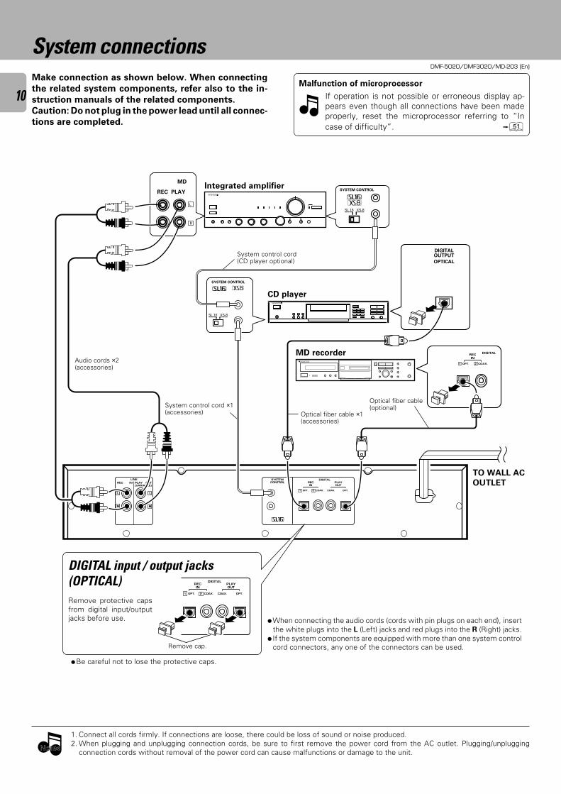
System connectionsMake connection as shown below. When connecting
the related system components, refer also to the in-
struction manuals of the related components.
Caution: Do not plug in the power lead until all connec-
tions are completed.
1. Connect all cords firmly. If connections are loose, there could be loss of sound or noise produced.2. When plugging and unplugging connection cords, be sure to first remove the power cord from the AC outlet. Plugging/unplugging
connection cords without removal of the power cord can cause malfunctions or damage to the unit.
Malfunction of microprocessor
If operation is not possible or erroneous display ap-pears even though all connections have been madeproperly, reset the microprocessor referring to “Incase of difficulty”. Q
÷When connecting the audio cords (cords with pin plugs on each end), insertthe white plugs into the L (Left) jacks and red plugs into the R (Right) jacks.
÷ If the system components are equipped with more than one system controlcord connectors, any one of the connectors can be used.
DIGITAL input / output jacks(OPTICAL)Remove protective capsfrom digital input/outputjacks before use.
Remove cap.
System control cord(CD player optional)
CD player
MD recorderAudio cords ×2(accessories)
Optical fiber cable(optional)
Optical fiber cable ×1(accessories)
System control cord ×1(accessories)
TO WALL AC
OUTLET
Integrated amplifier
NotesNotes
÷Be careful not to lose the protective caps.
DMF-5020/DMF3020/MD-203 (En)
11
About the system control connectionsConnecting system control cords after connecting a Kenwood audio component system lets you take advantage of
convenient system control operations.
There are two Kenwoood system control modes. Make connections according to the groups of terminal symbols shown
below.
[XS8] Mode : lets you combine F, f, and ƒ terminals
[SL16] Mode : for [SL16] terminals only
This unit is compatible.
You can connect this unit via system control if all other equipment using system control connections are set to the [SL16]
mode.
1. [SL16] equipment cannot be combined with [XR], [XS], and [XS8] equipment for systemoperations. If your equipment consists of this kind of combination, please do not connectany system control cords. Even without system control cords, normal operations can becarried out without affecting performance.
2. Even if your amplifier or receiver does not have a system control terminal, the systemcontrol functions between other components can be implemented partially by connectingsystem control cords to the system control terminals of other components.
3. Do not connect system control cords to any components other than those specified byKenwood. It may cause a malfunction and damage your equipment.
4. Be sure the system control plugs are inserted all the way in to the system control terminals.(See the figure at right.)
About the system control operationsRemote Control
Lets you operate this unit with the system remote supplied with the amplifier or receiver.
Automatic Operation
Automatically switches the input selector on the amplifier or receiver when you start playback from this unit.
Synchronized Recording
When recording a CD after setting the amplifier's input selector to CD, starting playback on the CD player allows to
start recording automatically in an interlocked operation.
÷Do not operate the CD player during recording of a digital source other than CD; otherwise malfunction may occur.÷Synchronized recording is not possible while the SOUND SYNCHRO REC, AUTO CUT and REC AUTO PAUSE function is operating.
§⁄
About the system control connections
Note on connection of optical-fiber cable
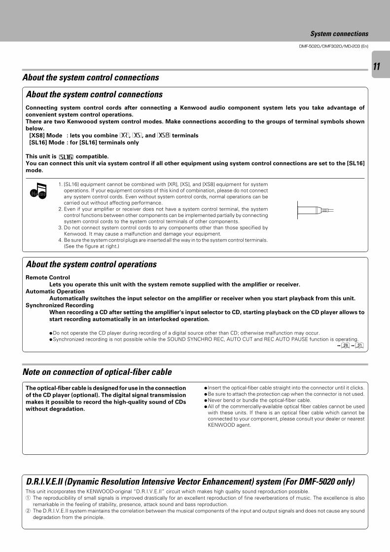
The optical-fiber cable is designed for use in the connection
of the CD player (optional). The digital signal transmission
makes it possible to record the high-quality sound of CDs
without degradation.
÷ Insert the optical-fiber cable straight into the connector until it clicks.÷Be sure to attach the protection cap when the connector is not used.÷Never bend or bundle the optical-fiber cable.÷All of the commercially-available optical fiber cables cannot be used
with these units. If there is an optical fiber cable which cannot beconnected to your component, please consult your dealer or nearestKENWOOD agent.
System connections
NotesNotes
D.R.I.V.E.II (Dynamic Resolution Intensive Vector Enhancement) system (For DMF-5020 only)This unit incorporates the KENWOOD-original “D.R.I.V.E.II” circuit which makes high quality sound reproduction possible.1 The reproducibility of small signals is improved drastically for an excellent reproduction of fine reverberations of music. The excellence is also
remarkable in the feeling of stability, presence, attack sound and bass reproduction.2 The D.R.I.V.E.II system maintains the correlation between the musical components of the input and output signals and does not cause any sound
degradation from the principle.
DMF-5020/DMF3020/MD-203 (En)
12
MIN
REC LEVEL
PHONESENTER
/TIME DISPLAY
REC MODE/CHARAC.
SET
REC INPUTMONITOR/DELETE
STANDBY
POWER
JOG DIAL
TITLE INPUT
EDIT/SPACE
MAX
DISC LOADING MECHANISM
STEREO MINIDISC RECORDER
1
37
¡
0
- ON – OFF
TIMER
REC OFF PLAY
2 3 4 5 6 7
@ # $ ^ £ )&
8 0
( ¡ ™ *! %
IN
REPEAT FADE
OVER
OUT
OVER (−dB)
(−dB)MONO
MANUALA . PAUSE
R
L
REMAIN
TOTAL
SINGLECOPY
TITLE
• • • • • • • • • • • •
∞∞
912 7 5 1340 30 21 18 0
1518 12 9 3640 30 27 24
15
21 0SEARCHPGM
MONITOR
ANALOG
32kHz
21 3
48kHz
44.1kHz
DIGITAL
1 9
OUTPUTLEVEL
4 ¢
REC
While the standby indicator of the unit is lit, a small amount of current is flowing into the unit's internal circuitry to back up the
memory. This condition is referred to as the standby mode of the unit. While the unit is in the standby mode, it can be turned
ON from the remote control unit.
Standby mode
Names and functions of parts
Display / Main unit
Display
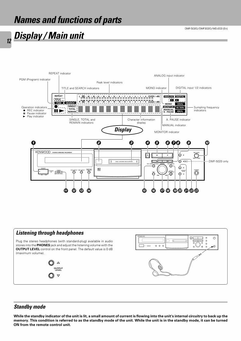
TITLE and SEARCH indicators MONO indicator
PGM (Program) indicatorPeak level indicators
Listening through headphonesPlug the stereo headphones (with standard-plug) available in audiostores into the PHONES jack and adjust the listening volume with theOUTPUT LEVEL control on the front panel. The default value is 0 dB(maximum volume).
ANALOG input indicator
DIGITAL input 1/2 indicators
REPEAT indicator
SINGLE, TOTAL andREMAIN indicators
Character informationdisplay
A. PAUSE indicator
MANUAL indicator
MONITOR indicator
Operation indicators¶ REC indicator8 Pause indicator3 Play indicator
Sumpling frequencyindicators
OUTPUTLEVEL
DMF-5020 only
DMF-5020/DMF3020/MD-203 (En)
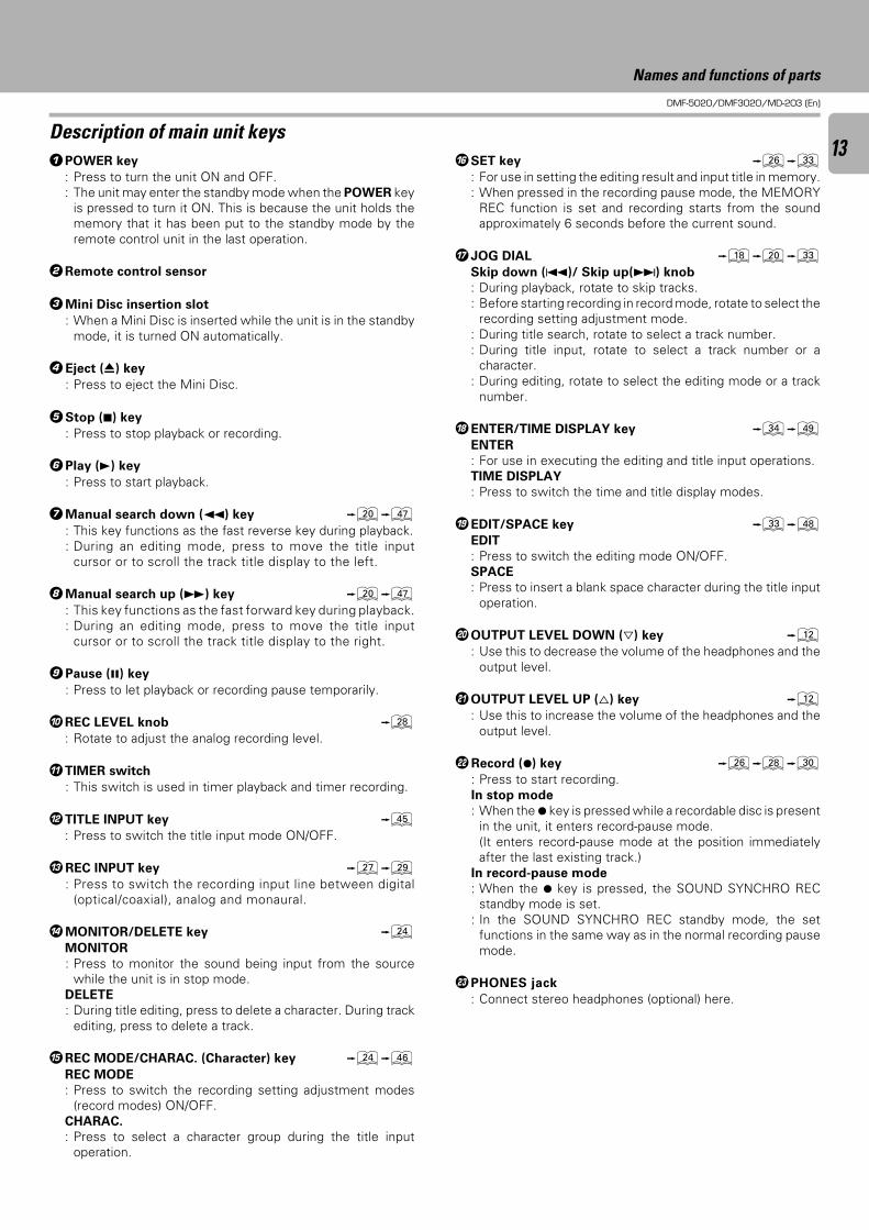
131POWER key
: Press to turn the unit ON and OFF.: The unit may enter the standby mode when the POWER key
is pressed to turn it ON. This is because the unit holds thememory that it has been put to the standby mode by theremote control unit in the last operation.
2Remote control sensor
3Mini Disc insertion slot
: When a Mini Disc is inserted while the unit is in the standbymode, it is turned ON automatically.
4Eject (0) key
: Press to eject the Mini Disc.
5Stop (7) key
: Press to stop playback or recording.
6Play (3) key
: Press to start playback.
7Manual search down (1) key )u: This key functions as the fast reverse key during playback.: During an editing mode, press to move the title input
cursor or to scroll the track title display to the left.
8Manual search up (¡) key )u: This key functions as the fast forward key during playback.: During an editing mode, press to move the title input
cursor or to scroll the track title display to the right.
9Pause (8) key
: Press to let playback or recording pause temporarily.
0REC LEVEL knob •: Rotate to adjust the analog recording level.
!TIMER switch
: This switch is used in timer playback and timer recording.
@TITLE INPUT key t: Press to switch the title input mode ON/OFF.
#REC INPUT key ¶ª: Press to switch the recording input line between digital
(optical/coaxial), analog and monaural.
$MONITOR/DELETE key ¢MONITOR
: Press to monitor the sound being input from the sourcewhile the unit is in stop mode.
DELETE
: During title editing, press to delete a character. During trackediting, press to delete a track.
%REC MODE/CHARAC. (Character) key ¢yREC MODE
: Press to switch the recording setting adjustment modes(record modes) ON/OFF.
CHARAC.
: Press to select a character group during the title inputoperation.
Description of main unit keys
Names and functions of parts
^SET key §‹: For use in setting the editing result and input title in memory.: When pressed in the recording pause mode, the MEMORY
REC function is set and recording starts from the soundapproximately 6 seconds before the current sound.
&JOG DIAL *)‹Skip down (4)/ Skip up(¢) knob
: During playback, rotate to skip tracks.: Before starting recording in record mode, rotate to select the
recording setting adjustment mode.: During title search, rotate to select a track number.: During title input, rotate to select a track number or a
character.: During editing, rotate to select the editing mode or a track
number.
*ENTER/TIME DISPLAY key ›oENTER
: For use in executing the editing and title input operations.TIME DISPLAY
: Press to switch the time and title display modes.
(EDIT/SPACE key ‹iEDIT
: Press to switch the editing mode ON/OFF.SPACE
: Press to insert a blank space character during the title inputoperation.
)OUTPUT LEVEL DOWN (fi) key @: Use this to decrease the volume of the headphones and the
output level.
¡OUTPUT LEVEL UP (%) key @: Use this to increase the volume of the headphones and the
output level.
™Record (¶) key §•º: Press to start recording.In stop mode
: When the ¶ key is pressed while a recordable disc is presentin the unit, it enters record-pause mode.(It enters record-pause mode at the position immediatelyafter the last existing track.)
In record-pause mode
: When the ¶ key is pressed, the SOUND SYNCHRO RECstandby mode is set.
: In the SOUND SYNCHRO REC standby mode, the setfunctions in the same way as in the normal recording pausemode.
£PHONES jack
: Connect stereo headphones (optional) here.
DMF-5020/DMF3020/MD-203 (En)
14
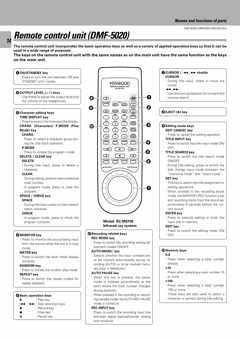
3Character editing keys
TIME DISPLAY key
: Press to switch the time and title display.CHARA. (Character)/ P.MODE (Play
Mode) key
CHARA.
: Press to select a character group dur-ing the title input operation.
P.MODE
: Press to initiate the program mode.DELETE / CLEAR key
DELETE
: During title input, press to delete acharacter.
CLEAR
: During editing, press to clear a selectedtrack number.
: In program mode, press to clear theprogram.
SPACE / CHECK key
SPACE
: During title input, press to insert a blankspace character.
CHECK
: In program mode, press to check theprogram contents.
8EJECT (0) key
9Editing mode keys
EDIT CANCEL key
: Press to cancel the editing operation.TITLE INPUT key
: Press to switch the title input mode ON/OFF.
TITLE SEARCH key
: Press to switch the title search modeON/OFF.
: During title editing, press to switch thetitle change input mode between the“overwrite mode” and “insert mode”.
SET key
: This key is used in the title assignment orediting operations.
: When pressed in the recording pausemode, the MEMORY REC function is setand recording starts from the sound ap-proximately 6 seconds before the cur-rent sound.
ENTER key
: Press to execute editing or enter theinput title in memory.
EDIT key
: Press to switch the editing mode ON/OFF.
Remote control unit (DMF-5020)The remote control unit incorporates the basic operation keys as well as a variety of applied operation keys so that it can be
used in a wide range of purposes.
The keys on the remote control unit with the same names as on the main unit have the same function as the keys
on the main unit.
Model: RC-M0705
Infrared ray system
4MONITOR key
: Press to monitor the sound being inputfrom the source while the unit is in stopmode.
METER key
: Press to switch the level meter displaycontents.
RANDOM key
: Press to initiate the random play mode.REPEAT key
: Press to switch the repeat modes forrepeat playback.
1ON/STANDBY key
: Press to turn the unit between ON andSTANDBY ( / ) modes.
6Recording-related keys
REC MODE key
: Press to switch the recording setting ad-justment modes ON/OFF.
AUTO/MANU. key
: Selects whether the track numbers areto be marked automatically during re-cording (AUTO) or to be marked manu-ally after it (MANUAL).
AUTO PAUSE key
: When this key is pressed, the pausemode is initiated automatically at thepoint where the track number changesduring playback.
: When pressed in the recording or record-ing standby mode, the AUTO REC PAUSEmode is turned on.
REC INPUT key
: Press to switch the recording input linebetween digital (optical/coaxial), analogand monaural.
EDIT CANCEL
MONITOR
÷
0
REC MODE
SET
1
GHI
4
PRS
7
& ( ) - /
+100
METER
AUTO/MANU.
INPUT
ABC
ENTER
2
JKL
5
TUV
8
QZ
0
RANDOM
AUTO PAUSE
SEARCH
DEF
EDIT
3
MNO
6
WXY
9
’ , : ? !
+10
REPEAT
8
REC INPUT
%
fi
CHARA.
DELETE
SPACE
TITLE
™™/CUR.L CUR.R/££
TIMEDISPLAY
OUTPUTLEVEL
POWER
REMOTE CONTROL UNITRC-M0705
4 ¢ £
7
CLEAR
CHECK
P.MODE
8
9
1
2
3
4
5
6
7
0
Names and functions of parts
5Basic operation keys
3 : Play key4 , ¢ : Skip down/up keys¶ : Record key7 : Stop key8 : Pause key
7CURSOR / 1 , ¡ shuttle
CURSOR
: During title input, rotate to move thecursor.
1 , ¡: Use this during playback for forward and
reverse search.
2OUTPUT LEVEL (%fi) keys
: Use these to adjust the output level andthe volume of the headphones.
0Numeric keys
0-9
: Press when selecting a track numberdirectly.
+10
: Press when selecting a track number 10or more.
+100
: Press when selecting a track number100 or more.
: These keys are also used to select acharacter or symbol during title editing.
DMF-5020/DMF3020/MD-203 (En)
15
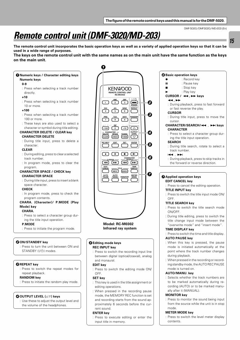
1Numeric keys / Character editing keys
Numeric keys
0-9
: Press when selecting a track numberdirectly.
+10
: Press when selecting a track number10 or more.
+100
: Press when selecting a track number100 or more.
: These keys are also used to select acharacter or symbol during title editing.
CHARACTER DELETE / CLEAR key
CHARACTER DELETE
: During title input, press to delete acharacter.
CLEAR
: During editing, press to clear a selectedtrack number.
: In program mode, press to clear theprogram.
CHARACTER SPACE / CHECK key
CHARACTER SPACE
: During title input, press to insert a blankspace character.
CHECK
: In program mode, press to check theprogram contents.
CHARA. (Character)/ P.MODE (Play
Mode) key
CHARA.
: Press to select a character group dur-ing the title input operation.
P.MODE
: Press to initiate the program mode.
5Editing mode keys
REC INPUT key
: Press to switch the recording input linebetween digital (optical/coaxial), analogand monaural.
EDIT key
: Press to switch the editing mode ON/OFF.
SET key
: This key is used in the title assignment orediting operations.
: When pressed in the recording pausemode, the MEMORY REC function is setand recording starts from the sound ap-proximately 6 seconds before the cur-rent sound.
ENTER key
: Press to execute editing or enter theinput title in memory.
7Applied operation keys
EDIT CANCEL key
: Press to cancel the editing operation.TITLE INPUT key
: Press to switch the title input mode ON/OFF.
TITLE SEARCH key
: Press to switch the title search modeON/OFF.
: During title editing, press to switch thetitle change input mode between the“overwrite mode” and “insert mode”.
TIME DISPLAY key
: Press to switch the time and title display.AUTO PAUSE key
: When this key is pressed, the pausemode is initiated automatically at thepoint where the track number changesduring playback.
: When pressed in the recording or record-ing standby mode, the AUTO REC PAUSEmode is turned on.
AUTO/MANU. key
: Selects whether the track numbers areto be marked automatically during re-cording (AUTO) or to be marked manu-ally after it (MANUAL).
MONITOR key
: Press to monitor the sound being inputfrom the source while the unit is in stopmode.
METER MODE key
: Press to switch the level meter displaycontents.
Remote control unit (DMF-3020/MD-203)The remote control unit incorporates the basic operation keys as well as a variety of applied operation keys so that it can be
used in a wide range of purposes.
The keys on the remote control unit with the same names as on the main unit have the same function as the keys
on the main unit.
Model: RC-M0302
Infrared ray system
3REPEAT key
: Press to switch the repeat modes forrepeat playback.
RANDOM key
: Press to initiate the random play mode.
2ON/STANDBY key
: Press to turn the unit between ON andSTANDBY ( / ) modes.
6Basic operation keys
¶ : Record key8 : Pause key7 : Stop key3 : Play keyCURSOR / 1 , ¡ keys
1 , ¡: During playback, press to fast forward
or fast reverse the play.CURSOR
: During title input, press to move thecursor.
CHARACTER/SEARCH/4 , ¢ keys
CHARACTER
: Press to select a character group dur-ing the title input operation.
SEARCH
: During title search, rotate to select atrack number.
4 , ¢: During playback, press to skip tracks in
the forward or reverse direction.
ABC
1
DEF
2 3
JKL MNO
5
GHI
4 6
TUV WXY
8
PRS
7 9
POWER
EDITCANCEL
QZ ’ , : ? !
0
& ( ) - /
+100 +10
RANDOM
REPEAT
SPACE CHARA.
CHECK
DELETE
CLEAR P.MODE
EDIT SETREC INPUT ENTER
8 7
¡ 1 4 ¢
AUTOPAUSE
AUTO/MANU.
METERMODE
TIMEDISPLAY
OUTPUTLEVEL
MONITOR
REMOTE CONTROL UNITRC-M0302
CURSOR
TITLE
CHARACTER/SEARCH
CHARACTER
%
fi
÷ £
INPUT SEARCH
2
3
4
5
6
7
1
4OUTPUT LEVEL (%fi) keys
: Use these to adjust the output level andthe volume of the headphones.
The figure of the remote control keys used this manual is for the DMF-5020.
DMF-5020/DMF3020/MD-203 (En)
16
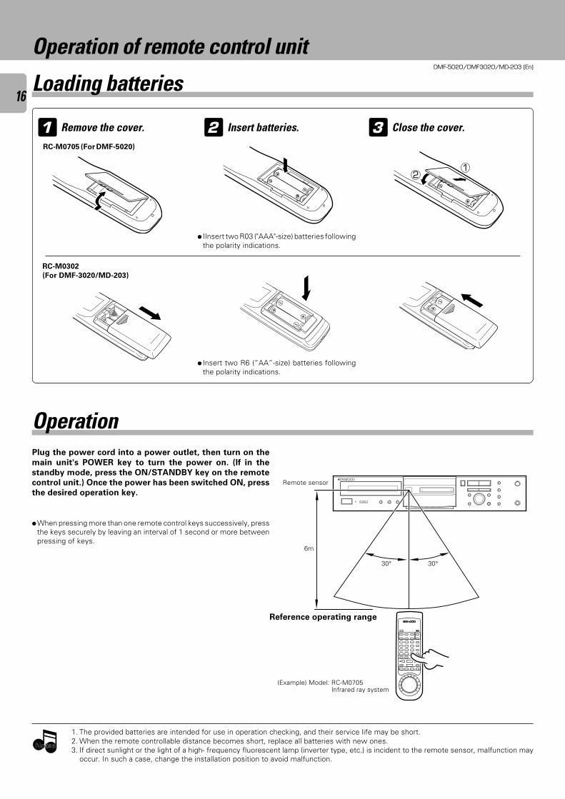
Operation of remote control unit
1 Remove the cover. Insert batteries.2 3 Close the cover.
÷ IInsert two R03 ("AAA"-size) batteries followingthe polarity indications.
Plug the power cord into a power outlet, then turn on the
main unit's POWER key to turn the power on. (If in the
standby mode, press the ON/STANDBY key on the remote
control unit.) Once the power has been switched ON, press
the desired operation key.
Operation
1. The provided batteries are intended for use in operation checking, and their service life may be short.2. When the remote controllable distance becomes short, replace all batteries with new ones.3. If direct sunlight or the light of a high- frequency fluorescent lamp (inverter type, etc.) is incident to the remote sensor, malfunction may
occur. In such a case, change the installation position to avoid malfunction.
÷When pressing more than one remote control keys successively, pressthe keys securely by leaving an interval of 1 second or more betweenpressing of keys.
Loading batteries
Reference operating range
(Example) Model: RC-M0705Infrared ray system
Remote sensor
21
NotesNotes
6m
30° 30°
÷ Insert two R6 (“AA”-size) batteries followingthe polarity indications.
RC-M0705 (For DMF-5020)
RC-M0302
(For DMF-3020/MD-203)
DMF-5020/DMF-3020/MD-203 (En)
17
1
2
3
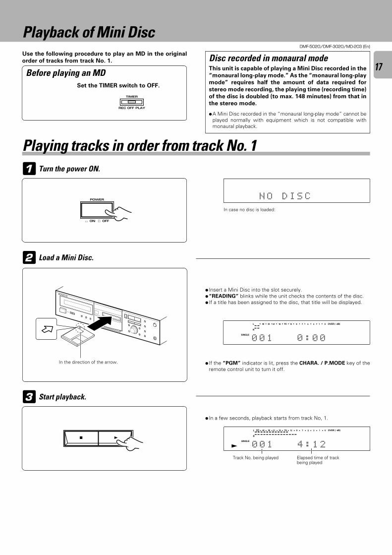
Use the following procedure to play an MD in the original
order of tracks from track No. 1.
Playback of Mini Disc
Before playing an MD
Load a Mini Disc.
Turn the power ON.
Start playback.
÷ In a few seconds, playback starts from track No, 1.
÷ If the “PGM” indicator is lit, press the CHARA. / P.MODE key of theremote control unit to turn it off.
÷ Insert a Mini Disc into the slot securely.÷“READING” blinks while the unit checks the contents of the disc.÷ If a title has been assigned to the disc, that title will be displayed.
Elapsed time of trackbeing played
Track No. being played
Disc recorded in monaural modeThis unit is capable of playing a Mini Disc recorded in the
“monaural long-play mode.” As the “monaural long-play
mode” requires half the amount of data required for
stereo mode recording, the playing time (recording time)
of the disc is doubled (to max. 148 minutes) from that in
the stereo mode.
÷A Mini Disc recorded in the “monaural long-play mode” cannot beplayed normally with equipment which is not compatible withmonaural playback.
In case no disc is loaded:
Set the TIMER switch to OFF.
Playing tracks in order from track No. 1
N O D I S C
SEARCHPGM
MONITOR
ANALOG
32kHz
21 3
48kHz
44.1kHz
DIGITAL
OVER (−dB)
R
L
SINGLE
0 0 1 0 : 0 0
15 912 7 5 1340 30 21 18 0
SEARCHPGM
MONITOR
ANALOG
32kHz
21 3
48kHz
44.1kHz
DIGITAL
OVER (−dB)
R
L
SINGLE
0 0 1 4 : 1 2
∞ 15 912 7 5 1340 30 21 18 0
SEARCHPGM
MONITOR
ANALOG
32kHz
21 3
48kHz
44.1kHz
DIGITAL
TIMER
REC OFF PLAY
In the direction of the arrow.
POWER
- ON – OFF
37
DMF-5020/DMF-3020/MD-203 (En)
18
1
2
3
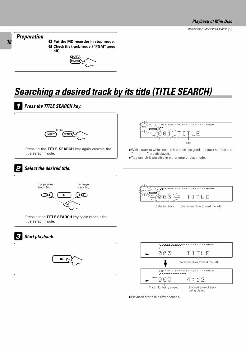
Pressing the TITLE SEARCH key again cancels thetitle serach mode.
Pressing the TITLE SEARCH key again cancels thetitle serach mode.
Preparation
Start playback.
Select the desired title.
Press the TITLE SEARCH key.
Searching a desired track by its title (TITLE SEARCH)
÷With a track to which no title has been assigned, the track number and“. . . . . . . .” are displayed.
÷Title search is possible in either stop or play mode.
Selected track Characters flow toward the left.
Title
÷Playback starts in a few seconds.
Track No. being played Elapsed time of trackbeing played
Characters flow toward the left.
1 Put the MD recorder in stop mode.
2 Check the track mode. (“PGM” goes
off)
Playback of Mini Disc
OVER (−dB)
R
L
TITLE
0 0 1 T I T L E
∞ 15 912 7 5 1340 30 21 18 0
SEARCHPGM
MONITOR
ANALOG
32kHz
21 3
48kHz
44.1kHz
DIGITAL
To smallertrack No.
To largertrack No. OVER (−dB)
R
L
TITLE
0 0 3 T I T L E
∞ 15 912 7 5 1340 30 21 18 0
SEARCHPGM
MONITOR
ANALOG
32kHz
21 3
48kHz
44.1kHz
DIGITAL
OVER (−dB)
R
L
SINGLE
0 0 3 4 : 1 2
∞ 15 912 7 5 1340 30 21 18 0
SEARCHPGM
MONITOR
ANALOG
32kHz
21 3
48kHz
44.1kHz
DIGITAL
OVER (−dB)
R
L
0 0 3 T I T L E
∞ 15 912 7 5 1340 30 21 18 0
SEARCHPGM
MONITOR
ANALOG
32kHz
21 3
48kHz
44.1kHz
DIGITAL
CHARA.
P.MODE
INPUT SEARCHTITLE
4 ¢ £
£
DMF-5020/DMF-3020/MD-203 (En)
19
1
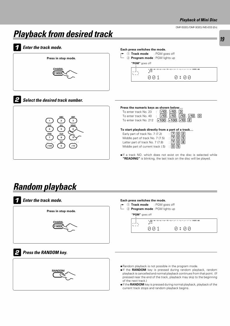
1
2 Press the RANDOM key.
Random playback
Each press switches the mode.
1 Track mode : PGM goes off2 Program mode : PGM lights up
Each press switches the mode.
1 Track mode : PGM goes off2 Program mode : PGM lights up
“PGM” goes off
÷Random playback is not possible in the program mode.÷ If the RANDOM key is pressed during random playback, random
playback is cancelled and normal playback continues from that point. (Ifpressed near the end of the track, playback may skip to the beginningof the next track.)
÷ If the RANDOM key is pressed during normal playback, playback of thecurrent track stops and random playback begins.
2
Enter the track mode.
Enter the track mode.
Select the desired track number.
Playback from desired track
“PGM” goes off
Press the numeric keys as shown below....
To enter track No. 23 : 0, 0, 3To enter track No. 40 : 0, 0, 0, 0, )To enter track No. 212 : +100 , +100 ,0,2
To start playback directly from a part of a track....
Early part of track No. 7 (7.2) : 7)2Middle part of track No. 7 (7.5) : 7)5Latter part of track No. 7 (7.8) : 7)8Middle part of current track (.5) : )5
÷ If a track NO. which does not exist on the disc is selected while“READING” is blinking, the last track on the disc will be played.
Playback of Mini Disc
OVER (−dB)
R
L
0 0 1 0 : 0 0
∞ 15 912 7 5 1340 30 21 18 0
SEARCHPGM
MONITOR
ANALOG
32kHz
21 3
48kHz
44.1kHz
DIGITAL
OVER (−dB)
R
L
0 0 1 0 : 0 0
∞ 15 912 7 5 1340 30 21 18 0
SEARCHPGM
MONITOR
ANALOG
32kHz
21 3
48kHz
44.1kHz
DIGITAL
Press in stop mode.
Press in stop mode.
CHARA.
P.MODE
1
GHI
4
PRS
7
& ( ) - /
+100
ABC
2
JKL
5
TUV
8
QZ
0
DEF
3
MNO
6
WXY
9
’ , : ? !
+10
CHARA.
P.MODE
RANDOM
DMF-5020/DMF-3020/MD-203 (En)
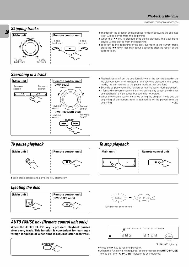
20 ÷The track in the direction of the pressed key is skipped, and the selectedtrack will be played from the beginning.
÷When the 4 key is pressed once during playback, the track beingplayed will be played from the beginning.
÷To return to the beginning of the previous track to the current track,press the 4 key in less than about 2 seconds after the restart of thecurrent track.
To skipforward
To skipforward
To skipbackward
To skipbackward
Searching in a track
Skipping tracks
Reversesearch
Reversesearch
Forwardsearch
Forwardsearch
To pause playback
÷Each press pauses and plays the MD alternately.
÷Playback restarts from the position with which the key is released or thejog dial operation is terminated. (If the key was pressed in the pausemode, the unit returns to the pause mode at that position.)
÷Sound is output when using forward or reverse search during playback.÷ If forward or reverse search is started during play-pause, the disc can
be searched at a high speed but sound is not output.÷When the reverse search is started during the program mode and the
beginning of the current track is attained, it will be played from thebeginning. ¡
To stop playback
Ejecting the disc
Mini Disc has been ejected.
AUTO PAUSE key (Remote control unit only)When the AUTO PAUSE key is pressed, playback pauses
after every track. This function is convenient for learning a
foreign language or when time is required after each track.
÷Press the 3 key to resume playback.÷When this function is not required, be sure to press the AUTO PAUSE
key so that the “A. PAUSE” indicator is extinguished.
“A. PAUSE” lights up
Playback of Mini Disc
N O D I S CEJECT
OVER (−dB)
A . PAUSE
R
L
0 0 2 0 : 0 0
∞ 15 912 7 5 1340 30 21 18 0
SEARCHPGM
MONITOR
ANALOG
32kHz
21 3
48kHz
44.1kHz
DIGITAL
4 ¢ JOG DIAL
4 ¢
4 ¢ £
Main unit Remote control unit
Main unit Remote control unit
™™/CUR.L CUR.R/££
(DMF-5020)
AUTO PAUSE
Main unit Remote control unit
Main unit Remote control unit Main unit Remote control unit
(DMF-5020 only)
0
8 7
(DMF-3020/MD-203)Reversesearch
Forwardsearch
1 ¡
37
0
¡ 1CURSOR
DMF-5020/DMF-3020/MD-203 (En)
21
1 Initiate the program mode.
2
3
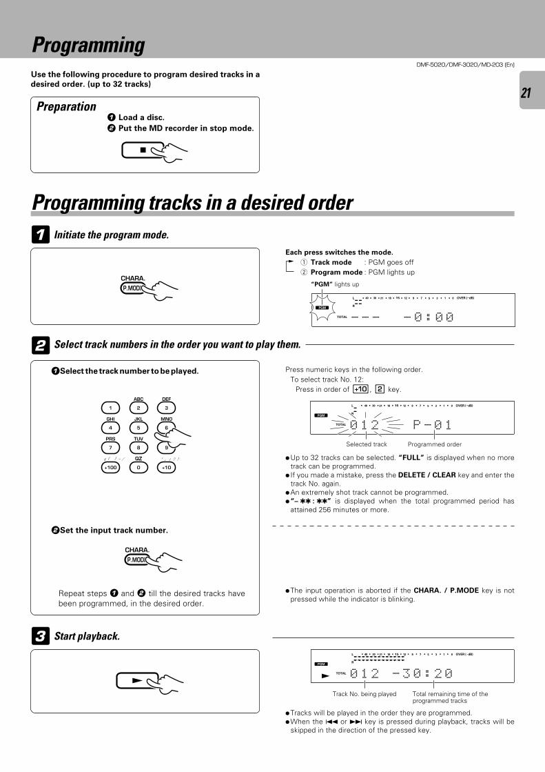
1 Load a disc.
2 Put the MD recorder in stop mode.
ProgrammingUse the following procedure to program desired tracks in a
desired order. (up to 32 tracks)
Preparation
Select track numbers in the order you want to play them.
Start playback.
1Select the track number to be played.
2Set the input track number.
Repeat steps 1 and 2 till the desired tracks havebeen programmed, in the desired order.
Press numeric keys in the following order.To select track No. 12:
Press in order of 0, 2 key.
÷Up to 32 tracks can be selected. “FULL” is displayed when no moretrack can be programmed.
÷ If you made a mistake, press the DELETE / CLEAR key and enter thetrack No. again.
÷An extremely shot track cannot be programmed.÷“– : ” is displayed when the total programmed period has
attained 256 minutes or more.
÷Tracks will be played in the order they are programmed.÷When the 4 or ¢ key is pressed during playback, tracks will be
skipped in the direction of the pressed key.
Total remaining time of theprogrammed tracks
Track No. being played
÷The input operation is aborted if the CHARA. / P.MODE key is notpressed while the indicator is blinking.
“PGM” lights up
Selected track Programmed order
Programming tracks in a desired order
Each press switches the mode.
1 Track mode : PGM goes off2 Program mode : PGM lights up
OVER (−dB)
R
L
TOTAL - - - - 0 : 0 0
15 912 7 5 1340 30 21 18 0
SEARCHPGM
MONITOR
ANALOG
32kHz
21 3
48kHz
44.1kHz
DIGITAL
OVER (−dB)
R
L
TOTAL 0 1 2 P - 0 1
15 912 7 5 1340 30 21 18 0
SEARCHPGM
MONITOR
ANALOG
32kHz
21 3
48kHz
44.1kHz
DIGITAL
OVER (−dB)
R
L
TOTAL 0 1 2 - 3 0 : 2 0
15 912 7 5 1340 30 21 18 0
SEARCHPGM
MONITOR
ANALOG
32kHz
21 3
48kHz
44.1kHz
DIGITAL
7
CHARA.
P.MODE
1
GHI
4
PRS
7
& ( ) - /
+100
ABC
2
JKL
5
TUV
8
QZ
0
DEF
3
MNO
6
WXY
9
’ , : ? !
+10
CHARA.
P.MODE
£
DMF-5020/DMF-3020/MD-203 (En)
22
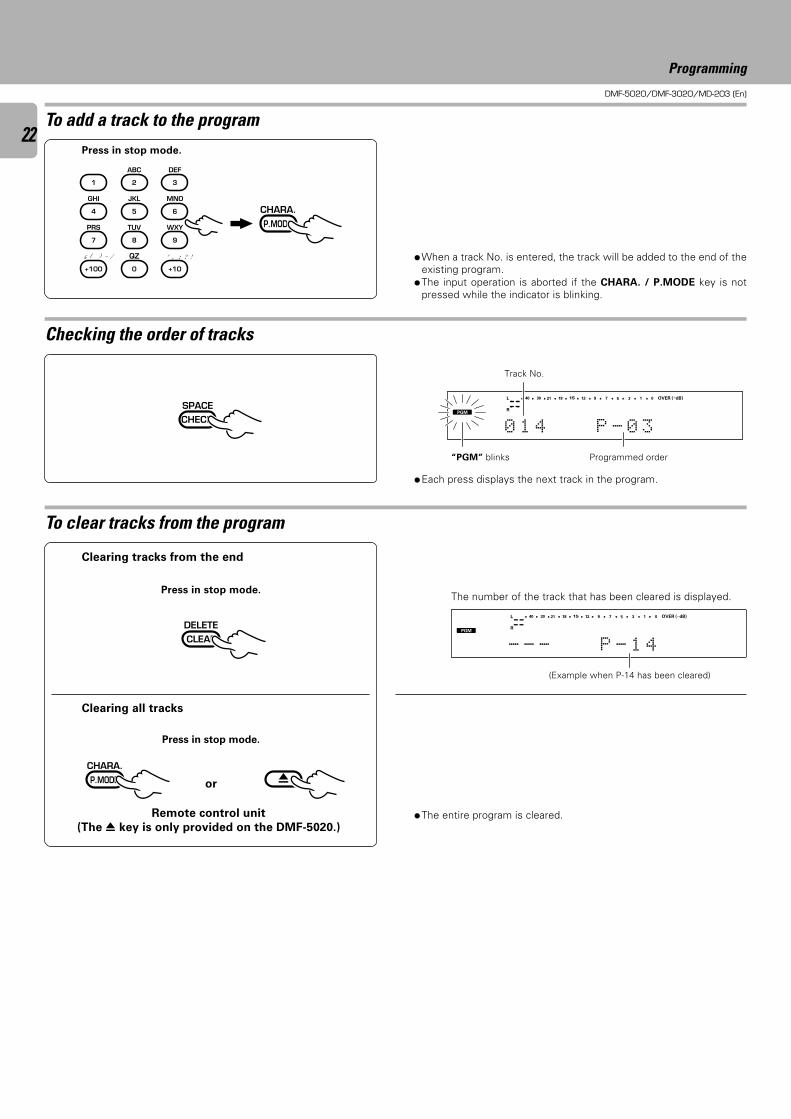
÷When a track No. is entered, the track will be added to the end of theexisting program.
÷The input operation is aborted if the CHARA. / P.MODE key is notpressed while the indicator is blinking.
÷The entire program is cleared.
÷Each press displays the next track in the program.
To add a track to the program
Checking the order of tracks
To clear tracks from the program
“PGM” blinks Programmed order
The number of the track that has been cleared is displayed.
(Example when P-14 has been cleared)
Clearing tracks from the end
Press in stop mode.
Clearing all tracks
Press in stop mode.
Press in stop mode.
or
Programming
Remote control unit
(The 0 key is only provided on the DMF-5020.)
OVER (−dB)
R
L
COPY
0 1 4 P - 0 3
15 912 7 5 1340 30 21 18 0
SEARCHPGM
MONITOR
ANALOG
32kHz
21 3
48kHz
44.1kHz
DIGITAL
OVER (−dB)
R
L
- - - P - 1 4
15 912 7 5 1340 30 21 18 0
SEARCHPGM
MONITOR
ANALOG
32kHz
21 3
48kHz
44.1kHz
DIGITAL
CHARA.
P.MODE
1
GHI
4
PRS
7
& ( ) - /
+100
ABC
2
JKL
5
TUV
8
QZ
0
DEF
3
MNO
6
WXY
9
’ , : ? !
+10
SPACECHECK
DELETECLEAR
CHARA.
P.MODE 0
Track No.
DMF-5020/DMF-3020/MD-203 (En)
23
1Enter the track mode.
2Enter the repeat mode.
3Start playback.
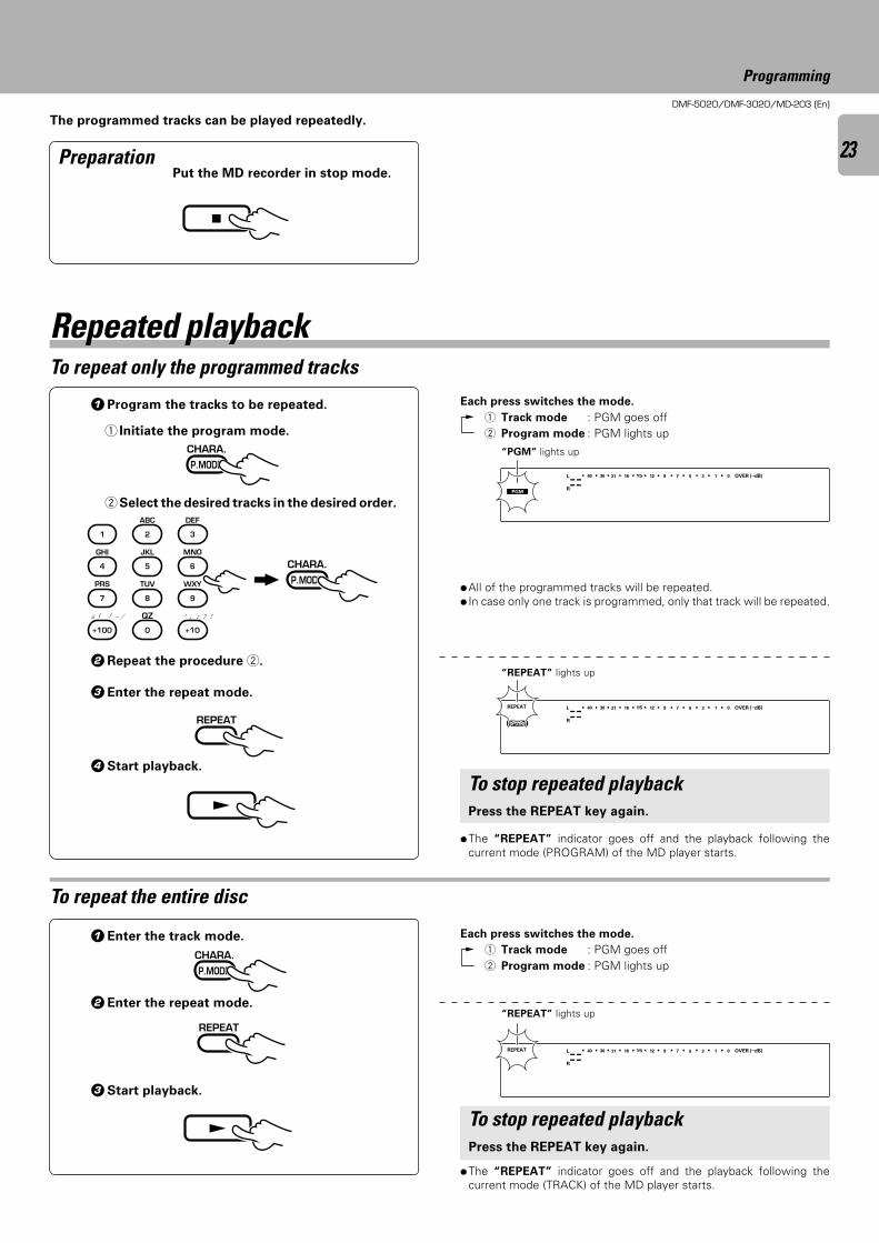
The programmed tracks can be played repeatedly.
Put the MD recorder in stop mode.
“REPEAT” lights up
÷All of the programmed tracks will be repeated.÷ In case only one track is programmed, only that track will be repeated.
Preparation
To repeat only the programmed tracks
1Program the tracks to be repeated.
1 Initiate the program mode.
2 Select the desired tracks in the desired order.
2Repeat the procedure 2.
3Enter the repeat mode.
4Start playback.
To repeat the entire disc
÷The “REPEAT” indicator goes off and the playback following thecurrent mode (TRACK) of the MD player starts.
To stop repeated playbackPress the REPEAT key again.
÷The “REPEAT” indicator goes off and the playback following thecurrent mode (PROGRAM) of the MD player starts.
To stop repeated playbackPress the REPEAT key again.
“REPEAT” lights up
“PGM” lights up
Repeated playback
Each press switches the mode.
1 Track mode : PGM goes off2 Program mode : PGM lights up
Each press switches the mode.
1 Track mode : PGM goes off2 Program mode : PGM lights up
Programming
OVER (−dB)
R
L 15 912 7 5 1340 30 21 18 0
SEARCHPGM
MONITOR
ANALOG
32kHz
21 3
48kHz
44.1kHz
DIGITAL
REPEAT OVER (−dB)
R
L 15 912 7 5 1340 30 21 18 0
SEARCHPGM
MONITOR
ANALOG
32kHz
21 3
48kHz
44.1kHz
DIGITAL
REPEAT OVER (−dB)
R
L 15 912 7 5 1340 30 21 18 0
SEARCHPGM
MONITOR
ANALOG
32kHz
21 3
48kHz
44.1kHz
DIGITAL
7
CHARA.
P.MODE
CHARA.
P.MODE
1
GHI
4
PRS
7
& ( ) - /
+100
ABC
2
JKL
5
TUV
8
QZ
0
DEF
3
MNO
6
WXY
9
’ , : ? !
+10
REPEAT
£
CHARA.
P.MODE
REPEAT
£
DMF-5020/DMF-3020/MD-203 (En)
24
Recording-related keys
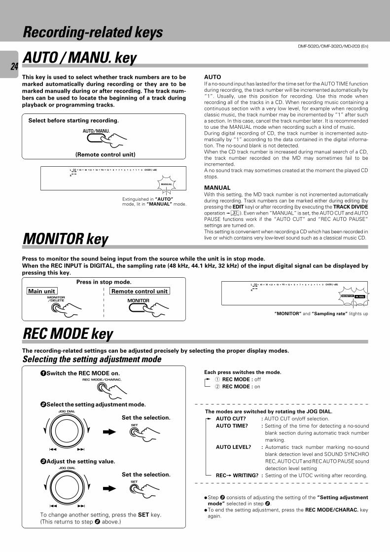
AUTO / MANU. keyThis key is used to select whether track numbers are to be
marked automatically during recording or they are to be
marked manually during or after recording. The track num-
bers can be used to locate the beginning of a track during
playback or programming tracks.
Select before starting recording.
AUTOIf a no-sound input has lasted for the time set for the AUTO TIME functionduring recording, the track number will be incremented automatically by“1”. Usually, use this position for recording. Use this mode whenrecording all of the tracks in a CD. When recording music containing acontinuous section with a very low level, for example when recordingclassic music, the track number may be incremented by “1” after sucha section. In this case, cancel the track number later. It is recommendedto use the MANUAL mode when recording such a kind of music.During digital recording of CD, the track number is incremented auto-matically by “1” according to the data contained in the digital informa-tion. The no-sound blank is not detected.When the CD track number is increased during manual search of a CD,the track number recorded on the MD may sometimes fail to beincremented.A no sound track may sometimes created at the moment the played CDstops.
MANUALWith this setting, the MD track number is not incremented automaticallyduring recording. Track numbers can be marked either during editing (bypressing the EDIT key) or after recording (by executing the TRACK DIVIDE
operation ‡). Even when “MANUAL” is set, the AUTO CUT and AUTOPAUSE functions work if the “AUTO CUT” and “REC AUTO PAUSE”settings are turned on.This setting is convenient when recording a CD which has been recorded inlive or which contains very low-level sound such as a classical music CD.
Press in stop mode.
Press to monitor the sound being input from the source while the unit is in stop mode.
When the REC INPUT is DIGITAL, the sampling rate (48 kHz, 44.1 kHz, 32 kHz) of the input digital signal can be displayed by
pressing this key.
MONITOR key
Extinguished in “AUTO”mode, lit in “MANUAL” mode.
“MONITOR” and “Sampling rate” litghts up
OVER (−dB)
MANUAL
R
L ∞ 15 912 7 5 1340 30 21 18 0
SEARCHPGM
MONITOR
ANALOG
32kHz
21 3
48kHz
44.1kHz
DIGITAL
OVER (−dB)
R
L ∞ 15 912 7 5 1340 30 21 18 0
SEARCHPGM
MONITOR
ANALOG
32kHz
21 3
48kHz
44.1kHz
DIGITAL
Main unit Remote control unit
(Remote control unit)
AUTO/MANU.
MONITORMONITOR/DELETE
Each press switches the mode.
1 REC MODE : off2 REC MODE : on
1Switch the REC MODE on.
2Select the setting adjustment mode.
3Adjust the setting value.
The recording-related settings can be adjusted precisely by selecting the proper display modes.
÷Step 3 consists of adjusting the setting of the “Setting adjustment
mode” selected in step 2.÷To end the setting adjustment, press the REC MODE/CHARAC. key
again.
Selecting the setting adjustment mode
The modes are switched by rotating the JOG DIAL.
AUTO CUT? : AUTO CUT on/off selection.AUTO TIME? : Setting of the time for detecting a no-sound
blank section during automatic track numbermarking.
AUTO LEVEL? : Automatic track number marking no-soundblank detection level and SOUND SYNCHROREC, AUTO CUT and REC AUTO PAUSE sounddetection level setting
REC= WRITING? : Setting of the UTOC writing after recording.
To change another setting, press the SET key.(This returns to step 2 above.)
REC MODE key
REC MODE/CHARAC.
4 ¢ JOG DIAL
4 ¢
SET
Set the selection.
4 ¢ JOG DIAL
4 ¢
SET
Set the selection.
DMF-5020/DMF-3020/MD-203 (En)
25
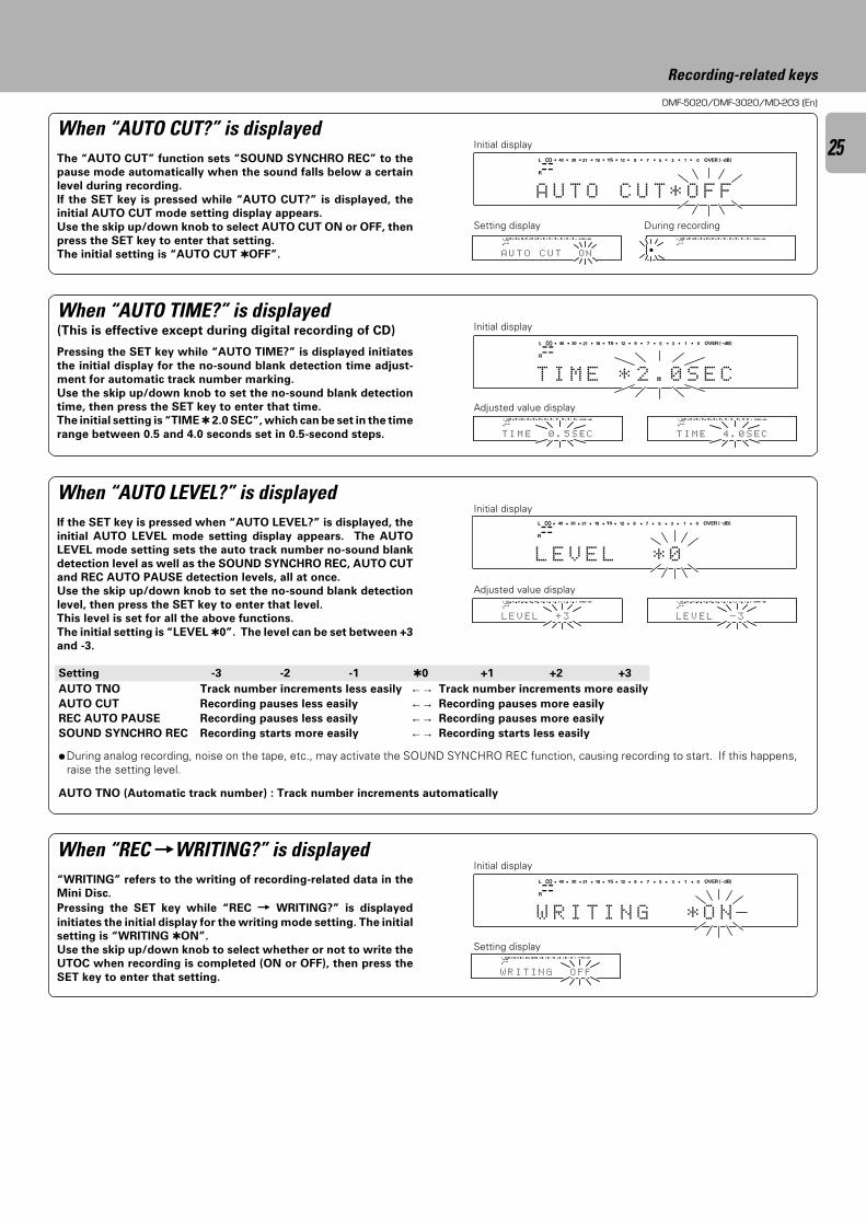
When “REC =WRITING?” is displayed“WRITING” refers to the writing of recording-related data in the
Mini Disc.
Pressing the SET key while “REC = WRITING?” is displayed
initiates the initial display for the writing mode setting. The initial
setting is “WRITING ON”.
Use the skip up/down knob to select whether or not to write the
UTOC when recording is completed (ON or OFF), then press the
SET key to enter that setting.
Initial display
Adjusted value display
Adjusted value display
Initial display
Initial display
Setting display
Recording-related keys
OVER (−dB)
R
L
L E V E * 0L
∞ 15 912 7 5 1340 30 21 18 0
SEARCHPGM
MONITOR
ANALOG
32kHz
21 3
48kHz
44.1kHz
DIGITAL
OVER (−dB)
R
L
FFTIRW
∞ 15 912 7 5 1340 30 21 18 0
SEARCHPGM
MONITOR
ANALOG
32kHz
21 3
48kHz
44.1kHz
DIGITAL
NI G O
OVER (−dB)
R
L
W R I T GNI NO*
∞ 15 912 7 5 1340 30 21 18 0
SEARCHPGM
MONITOR
ANALOG
32kHz
21 3
48kHz
44.1kHz
DIGITAL
When “AUTO TIME?” is displayed(This is effective except during digital recording of CD)
When “AUTO LEVEL?” is displayed
Pressing the SET key while “AUTO TIME?” is displayed initiates
the initial display for the no-sound blank detection time adjust-
ment for automatic track number marking.
Use the skip up/down knob to set the no-sound blank detection
time, then press the SET key to enter that time.
The initial setting is “TIME 2.0 SEC”, which can be set in the time
range between 0.5 and 4.0 seconds set in 0.5-second steps.
If the SET key is pressed when “AUTO LEVEL?” is displayed, the
initial AUTO LEVEL mode setting display appears. The AUTO
LEVEL mode setting sets the auto track number no-sound blank
detection level as well as the SOUND SYNCHRO REC, AUTO CUT
and REC AUTO PAUSE detection levels, all at once.
Use the skip up/down knob to set the no-sound blank detection
level, then press the SET key to enter that level.
This level is set for all the above functions.
The initial setting is “LEVEL 0”. The level can be set between +3
and -3.
OVER (−dB)
R
L
T I M E . 02 S E C
∞ 15 912 7 5 1340 30 21 18 0
SEARCHPGM
MONITOR
ANALOG
32kHz
21 3
48kHz
44.1kHz
DIGITAL
*
Setting display
Initial displayWhen “AUTO CUT?” is displayedThe “AUTO CUT” function sets “SOUND SYNCHRO REC” to the
pause mode automatically when the sound falls below a certain
level during recording.
If the SET key is pressed while “AUTO CUT?” is displayed, the
initial AUTO CUT mode setting display appears.
Use the skip up/down knob to select AUTO CUT ON or OFF, then
press the SET key to enter that setting.
The initial setting is “AUTO CUT OFF”.
OVER (−dB)
R
L
A U T O C T *U O F F
∞ 15 912 7 5 1340 30 21 18 0
SEARCHPGM
MONITOR
ANALOG
32kHz
21 3
48kHz
44.1kHz
DIGITAL
OVER (−dB)
R
L
T NOCOT UUA
∞ 15 912 7 5 1340 30 21 18 0
SEARCHPGM
MONITOR
ANALOG
32kHz
21 3
48kHz
44.1kHz
DIGITAL OVER (−dB)
R
L ∞ 15 912 7 5 1340 30 21 18 0
SEARCHPGM
MONITOR
ANALOG
32kHz
21 3
48kHz
44.1kHz
DIGITAL
During recording
OVER (−dB)
R
L
CE50EMIT
∞ 15 912 7 5 1340 30 21 18 0
SEARCHPGM
MONITOR
ANALOG
32kHz
21 3
48kHz
44.1kHz
DIGITAL
. S
OVER (−dB)
R
L
CE04EMIT
∞ 15 912 7 5 1340 30 21 18 0
SEARCHPGM
MONITOR
ANALOG
32kHz
21 3
48kHz
44.1kHz
DIGITAL
. S
OVER (−dB)
R
L
EVEL
∞ 15 912 7 5 1340 30 21 18 0
SEARCHPGM
MONITOR
ANALOG
32kHz
21 3
48kHz
44.1kHz
DIGITAL
L + 3
OVER (−dB)
R
L
EVEL
∞ 15 912 7 5 1340 30 21 18 0
SEARCHPGM
MONITOR
ANALOG
32kHz
21 3
48kHz
44.1kHz
DIGITAL
L - 3
AUTO TNO (Automatic track number) : Track number increments automatically
Setting -3 -2 -1 0 +1 +2 +3
AUTO TNO Track number increments less easily ←→ Track number increments more easily
AUTO CUT Recording pauses less easily ←→ Recording pauses more easily
REC AUTO PAUSE Recording pauses less easily ←→ Recording pauses more easily
SOUND SYNCHRO REC Recording starts more easily ←→ Recording starts less easily
÷During analog recording, noise on the tape, etc., may activate the SOUND SYNCHRO REC function, causing recording to start. If this happens,raise the setting level.
DMF-5020/DMF-3020/MD-203 (En)
26
Recording-related keys
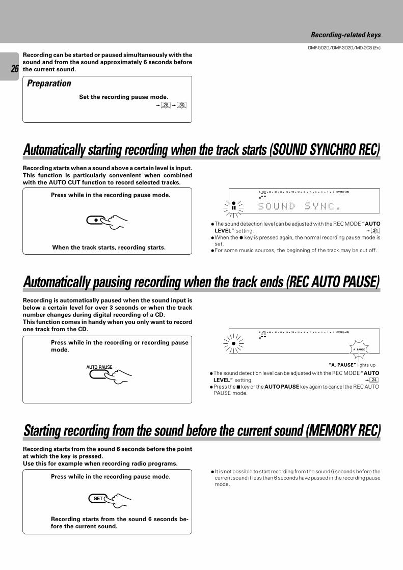
Set the recording pause mode.
•º
Recording can be started or paused simultaneously with the
sound and from the sound approximately 6 seconds before
the current sound.
Preparation
Automatically starting recording when the track starts (SOUND SYNCHRO REC)Recording starts when a sound above a certain level is input.
This function is particularly convenient when combined
with the AUTO CUT function to record selected tracks.
Press while in the recording pause mode.
When the track starts, recording starts.
÷
OVER (−dB)
R
L
S O U N D S Y N C .
∞ 15 912 7 5 1340 30 21 18 0
SEARCHPGM
MONITOR
ANALOG
32kHz
21 3
48kHz
44.1kHz
DIGITAL
÷The sound detection level can be adjusted with the REC MODE “AUTO
LEVEL” setting. ¢÷When the ¶ key is pressed again, the normal recording pause mode is
set.÷For some music sources, the beginning of the track may be cut off.
Automatically pausing recording when the track ends (REC AUTO PAUSE)Recording is automatically paused when the sound input is
below a certain level for over 3 seconds or when the track
number changes during digital recording of a CD.
This function comes in handy when you only want to record
one track from the CD.
Press while in the recording or recording pause
mode.
÷The sound detection level can be adjusted with the REC MODE “AUTO
LEVEL” setting. ¢÷Press the 7 key or the AUTO PAUSE key again to cancel the REC AUTO
PAUSE mode.
AUTO PAUSE
OVER (−dB)
A . PAUSE
R
L ∞ 15 912 7 5 1340 30 21 18 0
SEARCHPGM
MONITOR
ANALOG
32kHz
21 3
48kHz
44.1kHz
DIGITAL
“A. PAUSE” lights up
Starting recording from the sound before the current sound (MEMORY REC)Recording starts from the sound 6 seconds before the point
at which the key is pressed.
Use this for example when recording radio programs.
Press while in the recording pause mode.
Recording starts from the sound 6 seconds be-
fore the current sound.
SET
÷ It is not possible to start recording from the sound 6 seconds before thecurrent sound if less than 6 seconds have passed in the recording pausemode.
DMF-5020/DMF-3020/MD-203 (En)
27
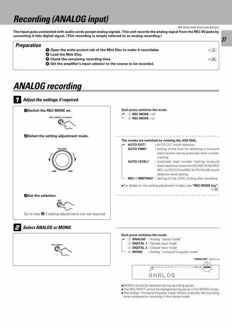
Adjust the settings if required.1
2
1Switch the REC MODE on.
2Select the setting adjustment mode.
3Set the selection.
Go to step 2 if setting adjustments are not required.
The input jacks connected with audio cords accept analog signals. This unit records the analog signal from the REC IN jacks by
converting it into digital signal. (This recording is simply referred to as analog recording.)
Recording (ANALOG input)
÷MONO cannot be selected during recording pause.÷The REC INPUT cannot be changed during pause in the MONO mode.÷The analog “monaural long-play mode”allows to double the recording
time compared to recording in the stereo mode.
Preparation
Each press switches the mode.
1 REC MODE : off2 REC MODE : on
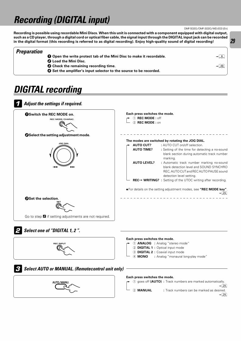
Select ANALOG or MONO.Each press switches the mode.
1 ANALOG : Analog “stereo mode”2 DIGITAL 1 : Optical input mode3 DIGITAL 2 : Coaxial input mode4 MONO : Analog “monaural long-play mode”
“ANALOG” lights up
1 Open the write protect tab of the Mini Disc to make it recordable. 82 Load the Mini Disc.
3 Check the remaining recording time. o4 Set the amplifier’s input selector to the source to be recorded.
ANALOG recording
÷For details on the setting adjustment modes, see “REC MODE key”.¢
OVER (−dB)
R
L
A N A L O G
∞ 15 912 7 5 1340 30 21 18 0
SEARCHPGM
MONITOR
ANALOG
32kHz
21 3
48kHz
44.1kHz
DIGITAL
REC MODE/CHARAC.
4 ¢ JOG DIAL
4 ¢
SET
REC INPUT
The modes are switched by rotating the JOG DIAL.
AUTO CUT? : AUTO CUT on/off selection.AUTO TIME? : Setting of the time for detecting a no-sound
blank section during automatic track numbermarking.
AUTO LEVEL? : Automatic track number marking no-soundblank detection level and SOUND SYNCHROREC, AUTO CUT and REC AUTO PAUSE sounddetection level setting.
REC= WRITING? : Setting of the UTOC writing after recording.
DMF-5020/DMF-3020/MD-203 (En)
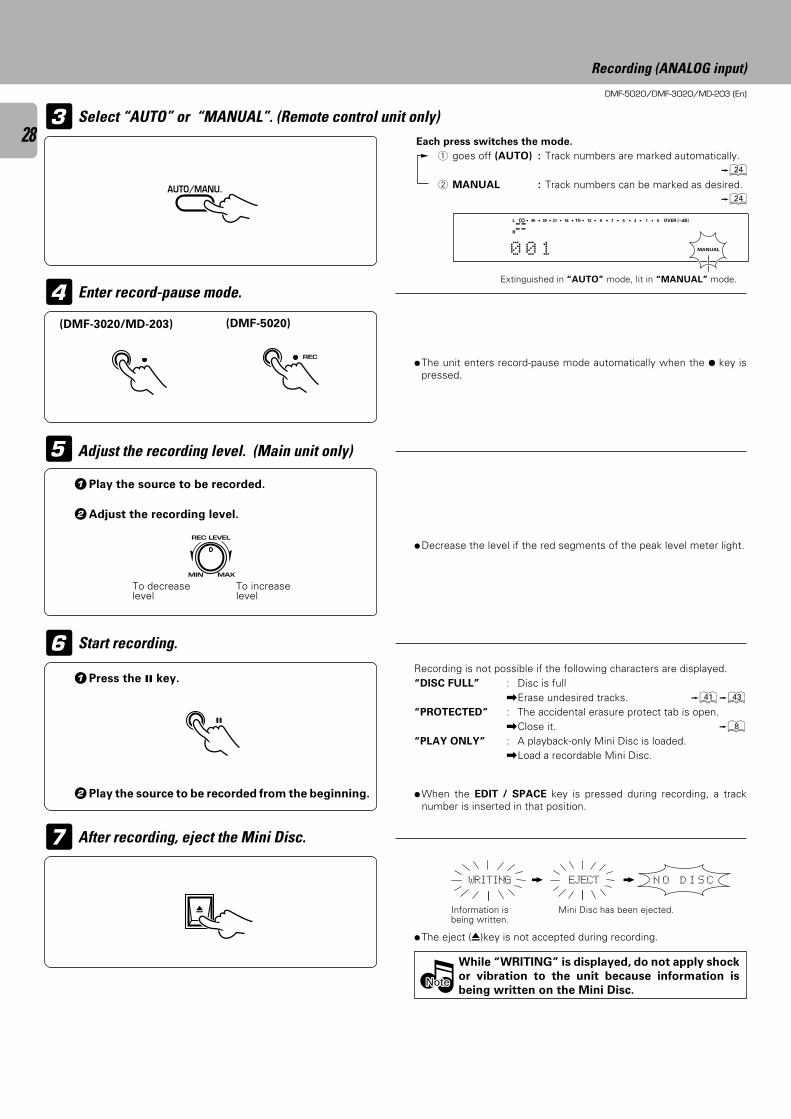
28 Each press switches the mode.
1 goes off (AUTO) : Track numbers are marked automatically.¢
2 MANUAL : Track numbers can be marked as desired.¢
÷The unit enters record-pause mode automatically when the ¶ key ispressed.
1Play the source to be recorded.
2Adjust the recording level.
÷Decrease the level if the red segments of the peak level meter light.
Extinguished in “AUTO” mode, lit in “MANUAL” mode.
Recording is not possible if the following characters are displayed.“DISC FULL” : Disc is full
\Erase undesired tracks. qe“PROTECTED” : The accidental erasure protect tab is open.
\Close it. 8“PLAY ONLY” : A playback-only Mini Disc is loaded.
\Load a recordable Mini Disc.
÷When the EDIT / SPACE key is pressed during recording, a tracknumber is inserted in that position.
After recording, eject the Mini Disc.
Start recording.
Information isbeing written.
Mini Disc has been ejected.
Select “AUTO” or “MANUAL”. (Remote control unit only)
Adjust the recording level. (Main unit only)
To increaselevel
To decreaselevel
1Press the 8 key.
2Play the source to be recorded from the beginning.
Recording (ANALOG input)
OVER (−dB)
MANUAL
R
L
0 0 1
∞ 15 912 7 5 1340 30 21 18 0
SEARCHPGM
MONITOR
ANALOG
32kHz
21 3
48kHz
44.1kHz
DIGITAL
N O D I S CWRITING EJECT
5
3
6
7
÷The eject (0)key is not accepted during recording.
While “WRITING” is displayed, do not apply shock
or vibration to the unit because information is
being written on the Mini Disc.NoteNoteNote
Enter record-pause mode.4
AUTO/MANU.
REC
(DMF-3020/MD-203) (DMF-5020)
MIN
REC LEVEL
MAX
0
DMF-5020/DMF-3020/MD-203 (En)
29
1
Go to step 2 if setting adjustments are not required.
2
3
1Switch the REC MODE on.
2Select the setting adjustment mode.
3Set the selection.
Adjust the settings if required.
Recording (DIGITAL input)Recording is possible using recordable Mini Discs. When this unit is connected with a component equipped with digital output,
such as a CD player, through a digital cord or optical fiber cable, the signal input through the DIGITAL input jack can be recorded
in the digital format (this recording is referred to as digital recording). Enjoy high-quality sound of digital recording!
Preparation1 Open the write protect tab of the Mini Disc to make it recordable. 82 Load the Mini Disc.
3 Check the remaining recording time. o4 Set the amplifier’s input selector to the source to be recorded.
Select AUTO or MANUAL. (Remotecontrol unit only)
Select one of “DIGITAL 1, 2 ”.
Each press switches the mode.
1 REC MODE : off2 REC MODE : on
Each press switches the mode.
1 ANALOG : Analog “stereo mode”2 DIGITAL 1 : Optical input mode3 DIGITAL 2 : Coaxial input mode4 MONO : Analog “monaural long-play mode”
Each press switches the mode.
1 goes off (AUTO) : Track numbers are marked automatically.¢
2 MANUAL : Track numbers can be marked as desired.¢
÷For details on the setting adjustment modes, see “REC MODE key”.¢
DIGITAL recording
REC MODE/CHARAC.
4 ¢ JOG DIAL
4 ¢
SET
REC INPUT
AUTO/MANU.
The modes are switched by rotating the JOG DIAL.
AUTO CUT? : AUTO CUT on/off selection.AUTO TIME? : Setting of the time for detecting a no-sound
blank section during automatic track numbermarking.
AUTO LEVEL? : Automatic track number marking no-soundblank detection level and SOUND SYNCHROREC, AUTO CUT and REC AUTO PAUSE sounddetection level setting.
REC= WRITING? : Setting of the UTOC writing after recording.
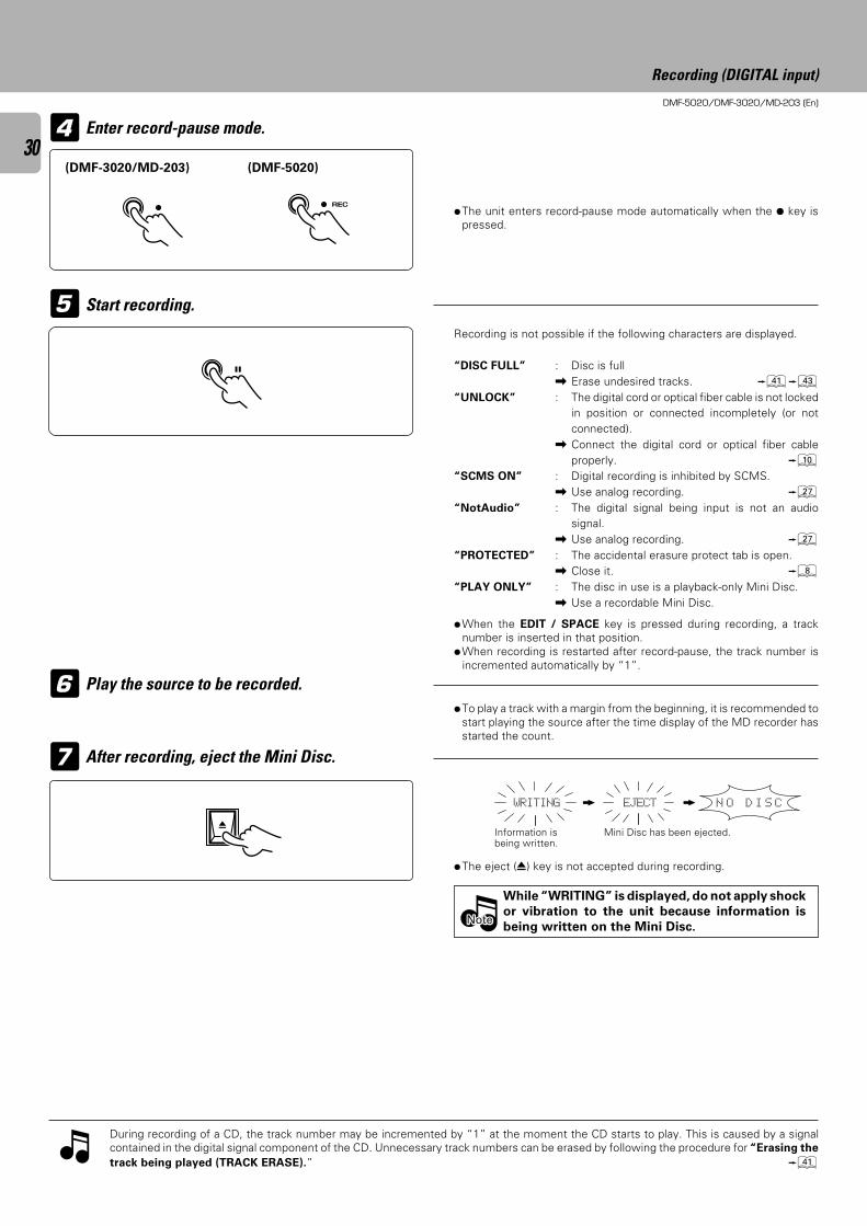
DMF-5020/DMF-3020/MD-203 (En)
30
5
Enter record-pause mode.4
÷The unit enters record-pause mode automatically when the ¶ key ispressed.
7
6
Recording is not possible if the following characters are displayed.
“DISC FULL” : Disc is full\ Erase undesired tracks. qe
“UNLOCK” : The digital cord or optical fiber cable is not lockedin position or connected incompletely (or notconnected).
\ Connect the digital cord or optical fiber cableproperly. 0
“SCMS ON” : Digital recording is inhibited by SCMS.\ Use analog recording. ¶
“NotAudio” : The digital signal being input is not an audiosignal.
\ Use analog recording. ¶“PROTECTED” : The accidental erasure protect tab is open.
\ Close it. 8“PLAY ONLY” : The disc in use is a playback-only Mini Disc.
\ Use a recordable Mini Disc.
Start recording.
During recording of a CD, the track number may be incremented by “1” at the moment the CD starts to play. This is caused by a signalcontained in the digital signal component of the CD. Unnecessary track numbers can be erased by following the procedure for “Erasing the
track being played (TRACK ERASE).” q
While “WRITING” is displayed, do not apply shock
or vibration to the unit because information is
being written on the Mini Disc.
Play the source to be recorded.
After recording, eject the Mini Disc.
÷To play a track with a margin from the beginning, it is recommended tostart playing the source after the time display of the MD recorder hasstarted the count.
÷When the EDIT / SPACE key is pressed during recording, a tracknumber is inserted in that position.
÷When recording is restarted after record-pause, the track number isincremented automatically by “1”.
÷The eject (0) key is not accepted during recording.
Information isbeing written.
Mini Disc has been ejected.
Recording (DIGITAL input)
N O D I S CWRITING EJECT
NoteNoteNote
REC
(DMF-3020/MD-203) (DMF-5020)
0
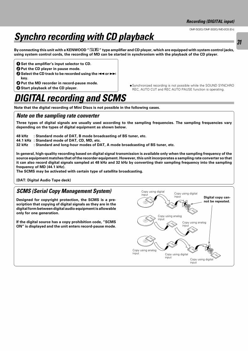
DMF-5020/DMF-3020/MD-203 (En)
31Synchro recording with CD playbackBy connecting this unit with a KENWOOD “ ” type amplifier and CD player, which are equipped with system control jacks,
using system control cords, the recording of MD can be started in synchronism with the playback of the CD player.
DIGITAL recording and SCMS
Recording (DIGITAL input)
1Set the amplifier’s input selector to CD.
2Put the CD player in pause mode.
3Select the CD track to be recorded using the 4 or ¢key.
4Put the MD recorder in record-pause mode.
5Start playback of the CD player.÷Synchronized recording is not possible while the SOUND SYNCHRO
REC, AUTO CUT and REC AUTO PAUSE function is operating.
Three types of digital signals are usually used according to the sampling frequencies. The sampling frequencies vary
depending on the types of digital equipment as shown below.
48 kHz : Standard mode of DAT, B mode broadcasting of BS tuner, etc.
44.1 kHz : Standard mode of DAT, CD, MD, etc.
32 kHz : Standard and long-hour modes of DAT, A mode broadcasting of BS tuner, etc.
In general, high-quality recording based on digital signal transmission is available only when the sampling frequency of the
source equipment matches that of the recorder equipment. However, this unit incorporates a sampling rate converter so that
it can also record digital signals sampled at 48 kHz and 32 kHz by converting their sampling frequency into the sampling
frequency of MD (44.1 kHz).
The SCMS may be activated with certain type of satellite broadcasting.
(DAT: Digital Audio Tape deck)
Note on the sampling rate converter
Designed for copyright protection, the SCMS is a pre-
scription that copying of digital signals as they are in the
digital form between digital audio equipment is allowable
only for one generation.
If the digital source has a copy prohibition code, “SCMS
ON” is displayed and the unit enters record-pause mode.
Copy using digitalinput
Copy using analoginput Copy using digital
input
Copy using analoginput
Copy using analoginput
Copy using digitalinput Copy using digital
input
Note that the digital recording of Mini Discs is not possible in the following cases.
SCMS (Serial Copy Management System)Digital copy can-
not be repeated.
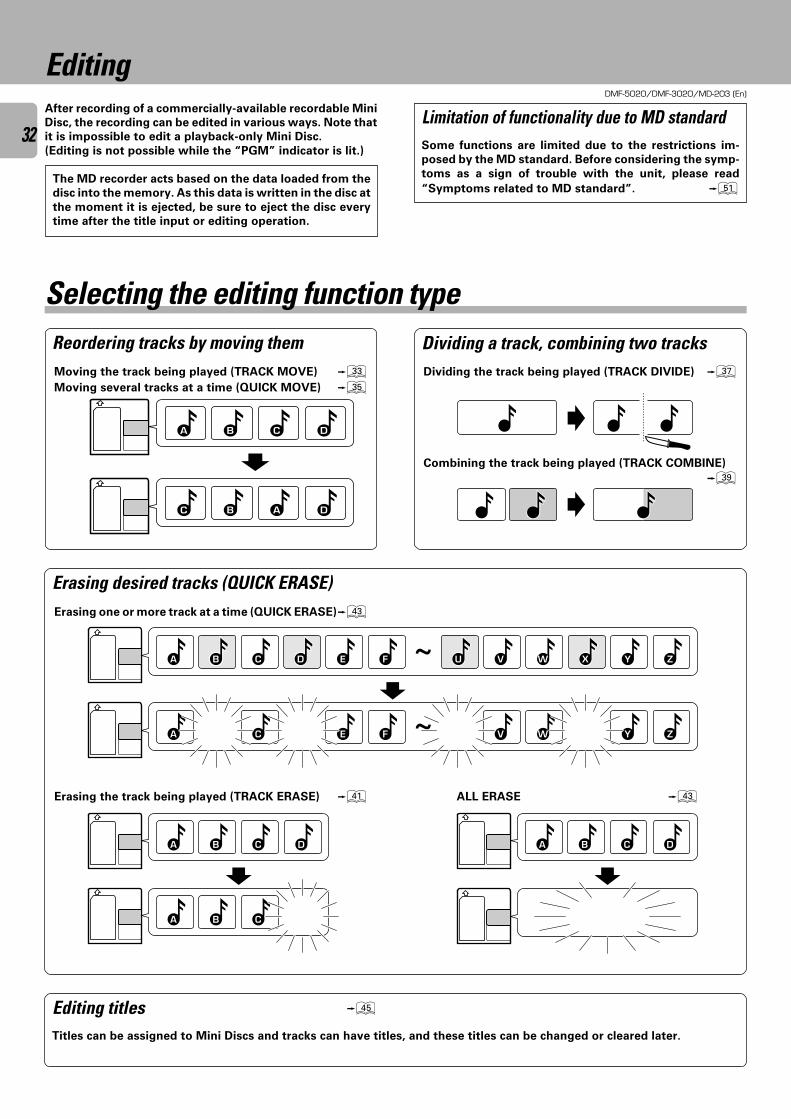
DMF-5020/DMF-3020/MD-203 (En)
32
Editing
Erasing desired tracks (QUICK ERASE)
Some functions are limited due to the restrictions im-
posed by the MD standard. Before considering the symp-
toms as a sign of trouble with the unit, please read
“Symptoms related to MD standard”. Q
Limitation of functionality due to MD standard
Editing titles t
Titles can be assigned to Mini Discs and tracks can have titles, and these titles can be changed or cleared later.
EditingAfter recording of a commercially-available recordable Mini
Disc, the recording can be edited in various ways. Note that
it is impossible to edit a playback-only Mini Disc.
(Editing is not possible while the “PGM” indicator is lit.)
Moving the track being played (TRACK MOVE) ‹Moving several tracks at a time (QUICK MOVE) fi
Reordering tracks by moving them
Selecting the editing function type
Erasing one or more track at a time (QUICK ERASE)e
Erasing the track being played (TRACK ERASE) q ALL ERASE e
DCBA
DABC
DCBA DCBA
CBA
ZCBA ED F ~ YXWVU
ZE F ~ YWVCA
Dividing a track, combining two tracksDividing the track being played (TRACK DIVIDE) ‡
Combining the track being played (TRACK COMBINE)
·
The MD recorder acts based on the data loaded from the
disc into the memory. As this data is written in the disc at
the moment it is ejected, be sure to eject the disc every
time after the title input or editing operation.
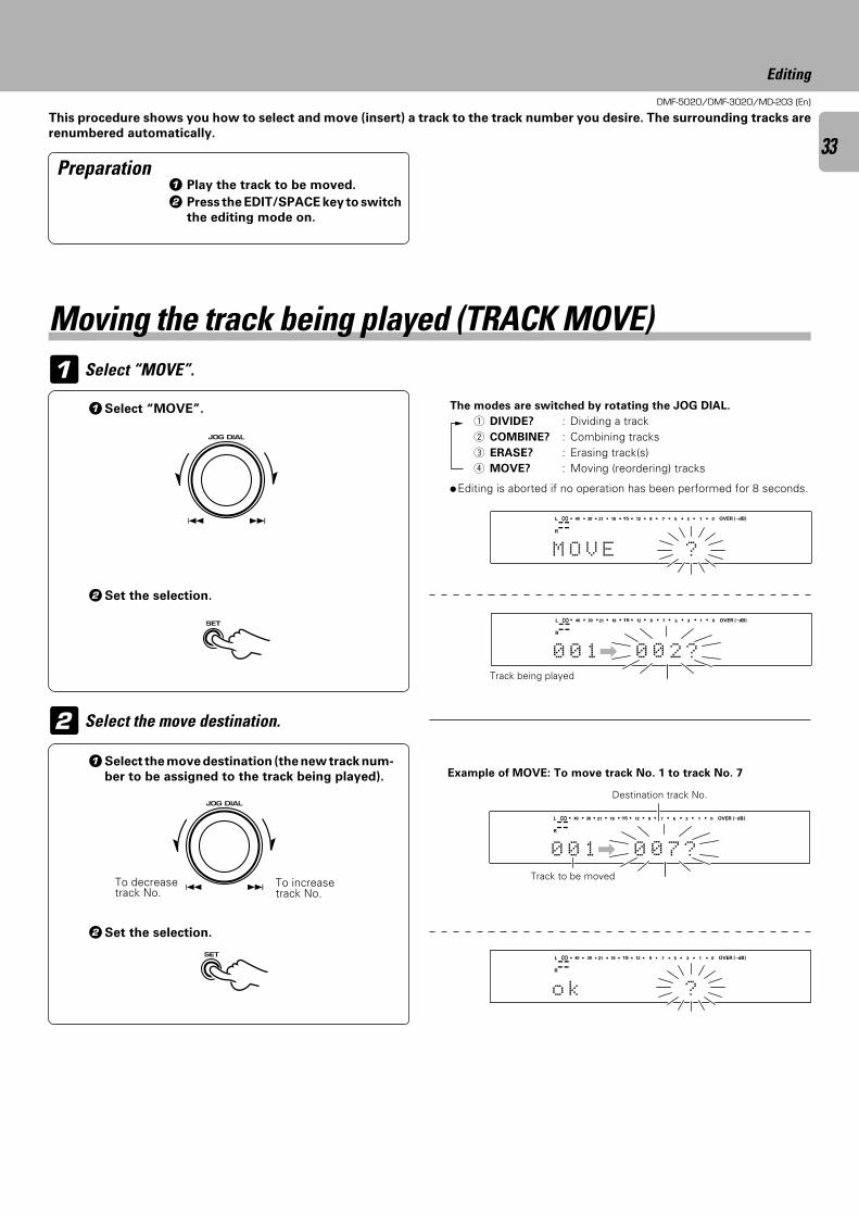
DMF-5020/DMF-3020/MD-203 (En)
33
Editing
The modes are switched by rotating the JOG DIAL.
1 DIVIDE? : Dividing a track2 COMBINE? : Combining tracks3 ERASE? : Erasing track(s)4 MOVE? : Moving (reordering) tracks
1Select the move destination (the new track num-
ber to be assigned to the track being played).
2Set the selection.
Select the move destination.
Example of MOVE: To move track No. 1 to track No. 7
This procedure shows you how to select and move (insert) a track to the track number you desire. The surrounding tracks are
renumbered automatically.
Preparation
Select “MOVE”.
1Select “MOVE”.
2Set the selection.
÷Editing is aborted if no operation has been performed for 8 seconds.
1 Play the track to be moved.
2 Press the EDIT/SPACE key to switch
the editing mode on.
Moving the track being played (TRACK MOVE)
To increasetrack No.
Destination track No.
Track to be moved
OVER (−dB)
R
L
M O V E ?
∞ 15 912 7 5 1340 30 21 18 0
SEARCHPGM
MONITOR
ANALOG
32kHz
21 3
48kHz
44.1kHz
DIGITAL
OVER (−dB)
R
L
0 0 1\ 0 0 2 ?
∞ 15 912 7 5 1340 30 21 18 0
SEARCHPGM
MONITOR
ANALOG
32kHz
21 3
48kHz
44.1kHz
DIGITAL
1
2
4 ¢ JOG DIAL
4 ¢
SET
4 ¢ JOG DIAL
4 ¢
SET
OVER (−dB)
R
L
0 0 1\ 0 0 7 ?
∞ 15 912 7 5 1340 30 21 18 0
SEARCHPGM
MONITOR
ANALOG
32kHz
21 3
48kHz
44.1kHz
DIGITAL
OVER (−dB)
R
L
o k ?
∞ 15 912 7 5 1340 30 21 18 0
SEARCHPGM
MONITOR
ANALOG
32kHz
21 3
48kHz
44.1kHz
DIGITAL
Track being played
To decreasetrack No.
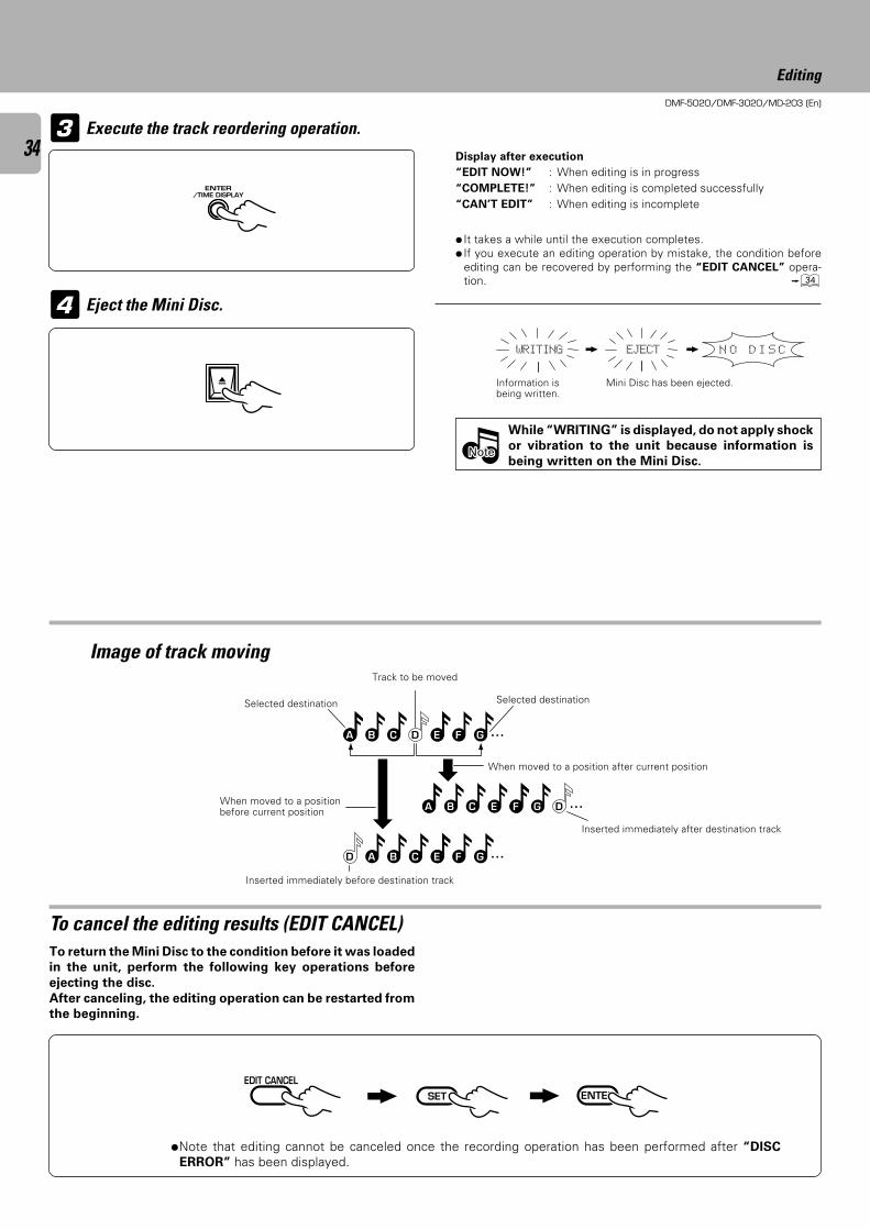
DMF-5020/DMF-3020/MD-203 (En)
34
Editing
3
÷ It takes a while until the execution completes.÷ If you execute an editing operation by mistake, the condition before
editing can be recovered by performing the “EDIT CANCEL” opera-tion. ›
Execute the track reordering operation.
Eject the Mini Disc.
While “WRITING” is displayed, do not apply shock
or vibration to the unit because information is
being written on the Mini Disc.
When moved to a positionbefore current position
Track to be moved
To cancel the editing results (EDIT CANCEL)To return the Mini Disc to the condition before it was loaded
in the unit, perform the following key operations before
ejecting the disc.
After canceling, the editing operation can be restarted from
the beginning.
Display after execution
“EDIT NOW!” : When editing is in progress“COMPLETE!” : When editing is completed successfully“CAN’T EDIT” : When editing is incomplete
Mini Disc has been ejected.Information isbeing written.
Image of track moving
Selected destinationSelected destination
When moved to a position after current position
Inserted immediately after destination track
Inserted immediately before destination track
NoteNoteNote
N O D I S CWRITING EJECT
A D F GCB E
A E G DCB F
D C F GBA E
4
÷Note that editing cannot be canceled once the recording operation has been performed after “DISC
ERROR” has been displayed.
ENTER/TIME DISPLAY
0
EDIT CANCELENTERSET
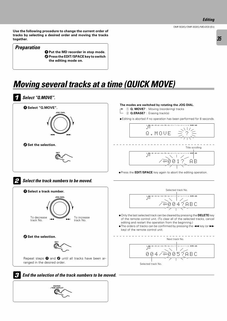
DMF-5020/DMF-3020/MD-203 (En)
35
Editing
Select “Q.MOVE”.
1Select “Q.MOVE”.
2Set the selection.
The modes are switched by rotating the JOG DIAL.
1 Q. MOVE? : Moving (reordering) tracks2 Q.ERASE? : Erasing track(s)
÷Press the EDIT/SPACE key again to abort the editing operation.
Select the track numbers to be moved.
Selected track No.
End the selection of the track numbers to be moved.
Selected track No.
Use the following procedure to change the current order of
tracks by selecting a desired order and moving the tracks
together.
Preparation
÷Only the last selected track can be cleared by pressing the DELETE keyof the remote control unit. (To clear all of the selected tracks, cancelediting and restart the operation from the beginning.)
÷The orders of tracks can be confirmed by pressing the 1 key (or ¡key) of the remote control unit.
1Select a track number.
2Set the selection.
To increasetrack No.
To decreasetrack No.
Repeat steps 1 and 2 until all tracks have been ar-ranged in the desired order.
1Put the MD recorder in stop mode.
2Press the EDIT/SPACE key to switch
the editing mode on.
Moving several tracks at a time (QUICK MOVE)
Title scrolling
Next track No.
1
2
3
÷Editing is aborted if no operation has been performed for 8 seconds.
4 ¢ JOG DIAL
4 ¢
SET
4 ¢ JOG DIAL
4 ¢
SET
ENTER/TIME DISPLAY
OVER (−dB)
R
L
Q . M O V E ?
∞ 15 912 7 5 1340 30 21 18 0
SEARCHPGM
MONITOR
ANALOG
32kHz
21 3
48kHz
44.1kHz
DIGITAL
OVER (−dB)
R
L
|/ 0 0 1 ? A B
∞ 15 912 7 5 1340 30 21 18 0
SEARCHPGM
MONITOR
ANALOG
32kHz
21 3
48kHz
44.1kHz
DIGITAL
OVER (−dB)
R
L
/|0 0 4 ? B CA
∞ 15 912 7 5 1340 30 21 18 0
SEARCHPGM
MONITOR
ANALOG
32kHz
21 3
48kHz
44.1kHz
DIGITAL
OVER (−dB)
R
L
0 0 4 /|0 0 5 ? B CA
∞ 15 912 7 5 1340 30 21 18 0
SEARCHPGM
MONITOR
ANALOG
32kHz
21 3
48kHz
44.1kHz
DIGITAL
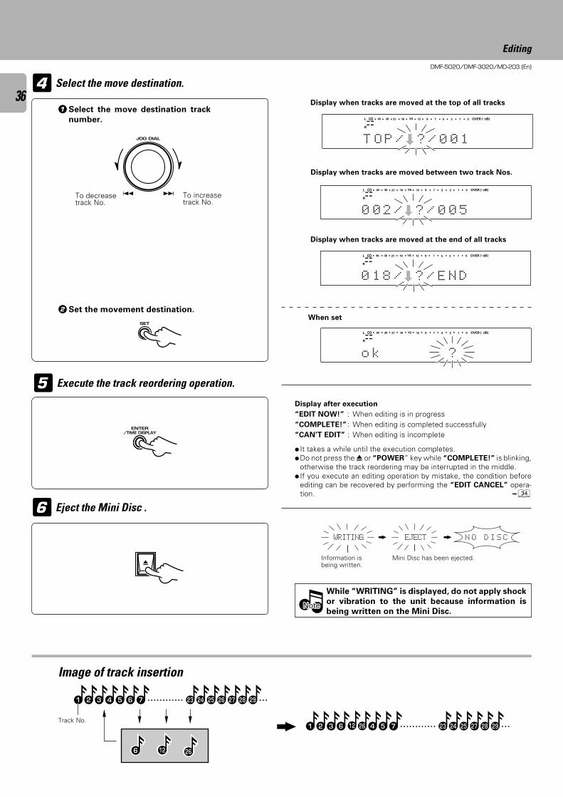
DMF-5020/DMF-3020/MD-203 (En)
36
Editing
1Select the move destination track
number.
2Set the movement destination.
Select the move destination.
Display when tracks are moved at the end of all tracks
To increasetrack No.
To decreasetrack No.
Eject the Mini Disc .
Execute the track reordering operation.
÷ It takes a while until the execution completes.÷Do not press the 0 or “POWER” key while “COMPLETE!” is blinking,
otherwise the track reordering may be interrupted in the middle.÷ If you execute an editing operation by mistake, the condition before
editing can be recovered by performing the “EDIT CANCEL” opera-tion. ›
While “WRITING” is displayed, do not apply shock
or vibration to the unit because information is
being written on the Mini Disc.
Display after execution
“EDIT NOW!” : When editing is in progress“COMPLETE!” : When editing is completed successfully“CAN’T EDIT” : When editing is incomplete
Image of track insertion
Display when tracks are moved between two track Nos.
Display when tracks are moved at the top of all tracks
Track No.
Mini Disc has been ejected.Information isbeing written.
0 1«
OVER (−dB)
R
L
/POT ? / 0
∞ 15 912 7 5 1340 30 21 18 0
SEARCHPGM
MONITOR
ANALOG
32kHz
21 3
48kHz
44.1kHz
DIGITAL
0 5«
OVER (−dB)
R
L
/200 ? / 0
∞ 15 912 7 5 1340 30 21 18 0
SEARCHPGM
MONITOR
ANALOG
32kHz
21 3
48kHz
44.1kHz
DIGITAL
N D«
OVER (−dB)
R
L
/810 ? / E
∞ 15 912 7 5 1340 30 21 18 0
SEARCHPGM
MONITOR
ANALOG
32kHz
21 3
48kHz
44.1kHz
DIGITAL
N O D I S CWRITING EJECT
1 2 3 4 5 6 7 25
12
26 27 28 2923 24
266
1 2 3 4 56 7 2512 27 28 2923 2426
NoteNoteNote
6
5
4
When set
OVER (−dB)
R
L
o k ?
∞ 15 912 7 5 1340 30 21 18 0
SEARCHPGM
MONITOR
ANALOG
32kHz
21 3
48kHz
44.1kHz
DIGITAL
4 ¢ JOG DIAL
4 ¢
SET
ENTER/TIME DISPLAY
0
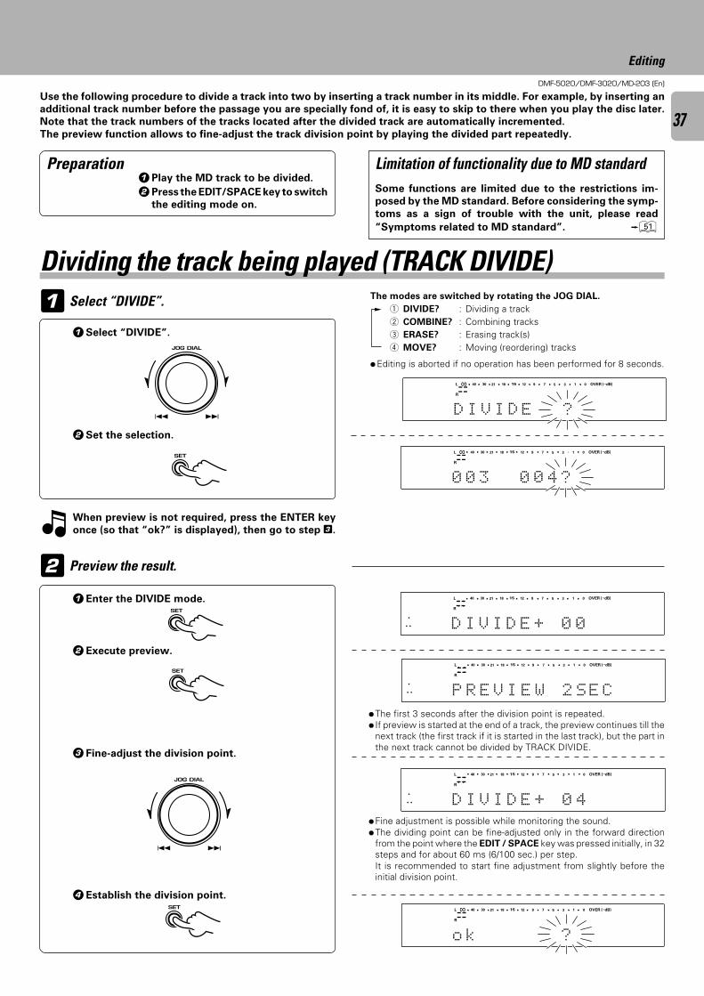
DMF-5020/DMF-3020/MD-203 (En)
37
Editing
Dividing the track being played (TRACK DIVIDE)The modes are switched by rotating the JOG DIAL.
1 DIVIDE? : Dividing a track2 COMBINE? : Combining tracks3 ERASE? : Erasing track(s)4 MOVE? : Moving (reordering) tracks
Use the following procedure to divide a track into two by inserting a track number in its middle. For example, by inserting an
additional track number before the passage you are specially fond of, it is easy to skip to there when you play the disc later.
Note that the track numbers of the tracks located after the divided track are automatically incremented.
The preview function allows to fine-adjust the track division point by playing the divided part repeatedly.
Select “DIVIDE”.
1Select “DIVIDE”.
2Set the selection.
Preview the result.
1Enter the DIVIDE mode.
2Execute preview.
3 Fine-adjust the division point.
4Establish the division point.
÷Fine adjustment is possible while monitoring the sound.÷The dividing point can be fine-adjusted only in the forward direction
from the point where the EDIT / SPACE key was pressed initially, in 32steps and for about 60 ms (6/100 sec.) per step.It is recommended to start fine adjustment from slightly before theinitial division point.
÷The first 3 seconds after the division point is repeated.÷ If preview is started at the end of a track, the preview continues till the
next track (the first track if it is started in the last track), but the part inthe next track cannot be divided by TRACK DIVIDE.
÷Editing is aborted if no operation has been performed for 8 seconds.
Preparation
When preview is not required, press the ENTER key
once (so that “ok?” is displayed), then go to step 3.
1Play the MD track to be divided.
2Press the EDIT/SPACE key to switch
the editing mode on.
Some functions are limited due to the restrictions im-
posed by the MD standard. Before considering the symp-
toms as a sign of trouble with the unit, please read
“Symptoms related to MD standard”. Q
Limitation of functionality due to MD standard
OVER (−dB)
R
L
D I V I D E ?
∞ 15 912 7 5 1340 30 21 18 0
SEARCHPGM
MONITOR
ANALOG
32kHz
21 3
48kHz
44.1kHz
DIGITAL
OVER (−dB)
R
L
0 0 3 0 0 4 ?
∞ 15 912 7 5 1340 30 21 18 0
SEARCHPGM
MONITOR
ANALOG
32kHz
21 3
48kHz
44.1kHz
DIGITAL
START
REPEAT DISC OVER (−dB)
R
L
REMAIN
TOTAL
SINGLEP.C.
TITLE
V EDIID 40+
∞ 15 912 7 5 1340 30 21 18 0
SEARCHPGM
MONITOR
ANALOG
32kHz
1 2
48kHz
44.1kHz
DIGITAL
OVER (−dB)
R
L
o k ?
∞ 15 912 7 5 1340 30 21 18 0
SEARCHPGM
MONITOR
ANALOG
32kHz
21 3
48kHz
44.1kHz
DIGITAL
1
2
START
REPEAT DISC OVER (−dB)
R
L
REMAIN
TOTAL
SINGLEP.C.
TITLE
E EIVRP ES2W C
∞ 15 912 7 5 1340 30 21 18 0
SEARCHPGM
MONITOR
ANALOG
32kHz
1 2
48kHz
44.1kHz
DIGITAL
START
REPEAT DISC OVER (−dB)
R
L
REMAIN
TOTAL
SINGLEP.C.
TITLE
V EDIID 00+
∞ 15 912 7 5 1340 30 21 18 0
SEARCHPGM
MONITOR
ANALOG
32kHz
1 2
48kHz
44.1kHz
DIGITAL
4 ¢ JOG DIAL
4 ¢
SET
SET
SET
4 ¢ JOG DIAL
4 ¢
SET
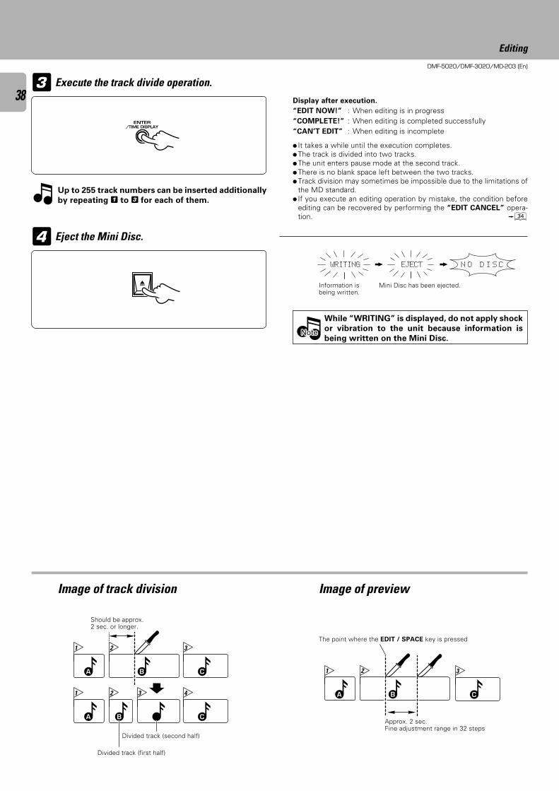
DMF-5020/DMF-3020/MD-203 (En)
38
Editing
÷ It takes a while until the execution completes.÷The track is divided into two tracks.÷The unit enters pause mode at the second track.÷There is no blank space left between the two tracks.÷Track division may sometimes be impossible due to the limitations of
the MD standard.÷ If you execute an editing operation by mistake, the condition before
editing can be recovered by performing the “EDIT CANCEL” opera-tion. ›
Execute the track divide operation.
Eject the Mini Disc.
Divided track (second half)
Divided track (first half)
Should be approx.2 sec. or longer.
Image of track division Image of preview
Display after execution.
“EDIT NOW!” : When editing is in progress“COMPLETE!” : When editing is completed successfully“CAN’T EDIT” : When editing is incomplete
While “WRITING” is displayed, do not apply shock
or vibration to the unit because information is
being written on the Mini Disc.
Up to 255 track numbers can be inserted additionally
by repeating 1 to 3 for each of them.
Approx. 2 sec.Fine adjustment range in 32 steps
The point where the EDIT / SPACE key is pressed
N O D I S CWRITING EJECT
A B C
1 2 3
A B C
1 2 43 A B
1 2
C
3
NoteNoteNote
3
4
Mini Disc has been ejected.Information isbeing written.
ENTER/TIME DISPLAY
0

DMF-5020/DMF-3020/MD-203 (En)
39
Editing
Select “COMBINE”.The modes are switched by rotating the JOG DIAL.
When pressed in play mode:
1 DIVIDE? : Dividing a track2 COMBINE? : Combining tracks3 ERASE? : Erasing track(s)4 MOVE? : Moving (reordering) tracks
Next track
1 Play one of the MD tracks to be
combined.
2 Press the EDIT/SPACE key to switch
the editing mode on.
Use the following procedure to combine two tracks into one by deleting a track number. This operation allows to connect
several tracks or a piece of music divided into several parts. After this operation, the track numbers of tracks located after the
combined tracks are decreased automatically.
1Select “COMBINE”.
2Set the selection.
÷ Editing is aborted if no operation has been performed for 8 seconds.
Select the track to be combined.
÷To combine two tracks during playback, press the EDIT/SPACE keywhile the first track is being played. (The track being played and thetrack immediately after it will be combined.)
÷ If the operation is started during playback, it pauses automatically.
Preparation
To combine the track with the next track to it, go to step
3.
Track being played
To combine track Nos. 5 and 7 :
Combining the track being played (TRACK COMBINE)
To decreasetrack No.
To increasetrack No.
Some functions are limited due to the restrictions im-
posed by the MD standard. Before considering the symp-
toms as a sign of trouble with the unit, please read
“Symptoms related to MD standard”. Q
Limitation of functionality due to MD standard
OVER (−dB)
R
L
C O M B I N E ?
∞ 15 912 7 5 1340 30 21 18 0
SEARCHPGM
MONITOR
ANALOG
32kHz
21 3
48kHz
44.1kHz
DIGITAL
OVER (−dB)
R
L
0 0 5 + 0 0 6 ?
∞ 15 912 7 5 1340 30 21 18 0
SEARCHPGM
MONITOR
ANALOG
32kHz
21 3
48kHz
44.1kHz
DIGITAL
1
2
OVER (−dB)
R
L
0 0 5 + 0 0 7 ?
∞ 15 912 7 5 1340 30 21 18 0
SEARCHPGM
MONITOR
ANALOG
32kHz
21 3
48kHz
44.1kHz
DIGITAL
OVER (−dB)
R
L
o k ?
∞ 15 912 7 5 1340 30 21 18 0
SEARCHPGM
MONITOR
ANALOG
32kHz
21 3
48kHz
44.1kHz
DIGITAL
4 ¢ JOG DIAL
4 ¢
SET
4 ¢ JOG DIAL
4 ¢
Set the selection.3
SET
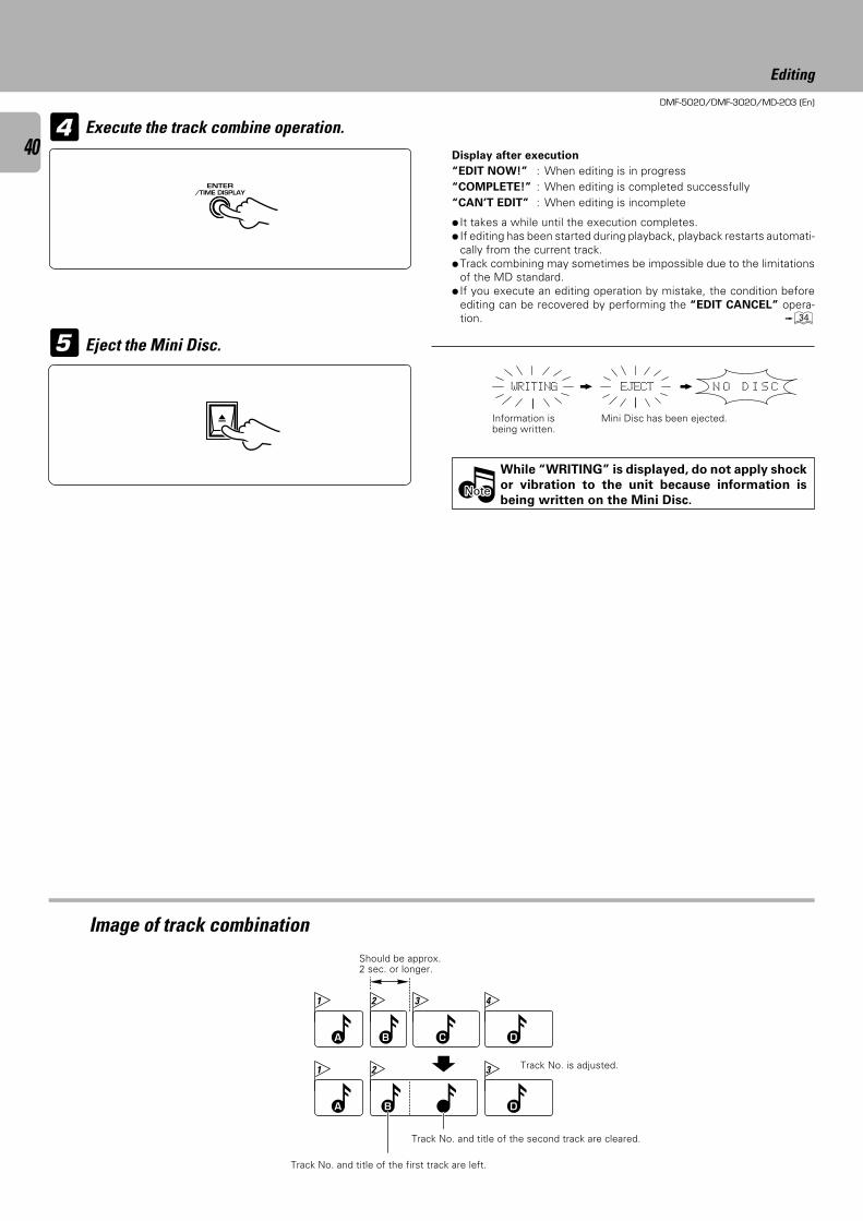
DMF-5020/DMF-3020/MD-203 (En)
40
Editing
÷ It takes a while until the execution completes.÷ If editing has been started during playback, playback restarts automati-
cally from the current track.÷Track combining may sometimes be impossible due to the limitations
of the MD standard.÷ If you execute an editing operation by mistake, the condition before
editing can be recovered by performing the “EDIT CANCEL” opera-tion. ›
Image of track combinationShould be approx.2 sec. or longer.
Execute the track combine operation.
Eject the Mini Disc.
While “WRITING” is displayed, do not apply shock
or vibration to the unit because information is
being written on the Mini Disc.
Display after execution
“EDIT NOW!” : When editing is in progress“COMPLETE!” : When editing is completed successfully“CAN’T EDIT” : When editing is incomplete
Mini Disc has been ejected.Information isbeing written.
Track No. and title of the first track are left.
Track No. is adjusted.
Track No. and title of the second track are cleared.
A B D
1 2 3
A B D
1 2 43
C
N O D I S CWRITING EJECT
NoteNoteNote
4
5
ENTER/TIME DISPLAY
0
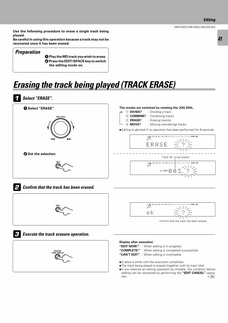
DMF-5020/DMF-3020/MD-203 (En)
41
Editing
1Play the MD track you wish to erase.
2Press the EDIT/SPACE key to switch
the editing mode on.
Confirm that the track has been erased.
Use the following procedure to erase a single track being
played.
Be careful in using this operation because a track may not be
recovered once it has been erased.
Select “ERASE”.
Execute the track erasure operation.
÷ It takes a while until the execution completes.÷The track being played is erased (together with its track title).÷ If you execute an editing operation by mistake, the condition before
editing can be recovered by performing the “EDIT CANCEL” opera-tion. ›
÷Editing is aborted if no operation has been performed for 8 seconds.
Display after execution
“EDIT NOW!” : When editing is in progress“COMPLETE!” : When editing is completed successfully“CAN’T EDIT” : When editing is incomplete
Confirm that the track has been erased.
Preparation
Erasing the track being played (TRACK ERASE)
1Select “ERASE”.
2Set the selection.
The modes are switched by rotating the JOG DIAL.
1 DIVIDE? : Dividing a track2 COMBINE? : Combining tracks3 ERASE? : Erasing track(s)4 MOVE? : Moving (reordering) tracks
Track No. to be erased
OVER (−dB)
R
L
E R A S E ?
∞ 15 912 7 5 1340 30 21 18 0
SEARCHPGM
MONITOR
ANALOG
32kHz
21 3
48kHz
44.1kHz
DIGITAL
OVER (−dB)
R
L
o k ?
∞ 15 912 7 5 1340 30 21 18 0
SEARCHPGM
MONITOR
ANALOG
32kHz
21 3
48kHz
44.1kHz
DIGITAL
1
2
3
OVER (−dB)
R
L
3 ?00-
∞ 15 912 7 5 1340 30 21 18 0
SEARCHPGM
MONITOR
ANALOG
32kHz
21 3
48kHz
44.1kHz
DIGITAL
|
4 ¢ JOG DIAL
4 ¢
SET
SET
ENTER/TIME DISPLAY
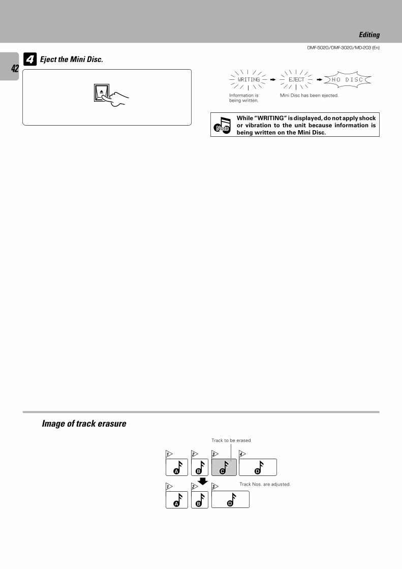
DMF-5020/DMF-3020/MD-203 (En)
42
Editing
Eject the Mini Disc.
Information isbeing written.
Mini Disc has been ejected.
While “WRITING” is displayed, do not apply shock
or vibration to the unit because information is
being written on the Mini Disc.
Track Nos. are adjusted.
Track to be erased
Image of track erasure
N O D I S CWRITING EJECT
NoteNoteNote
A B D
1 2 43
C
A B
1 2 3
D
4
0
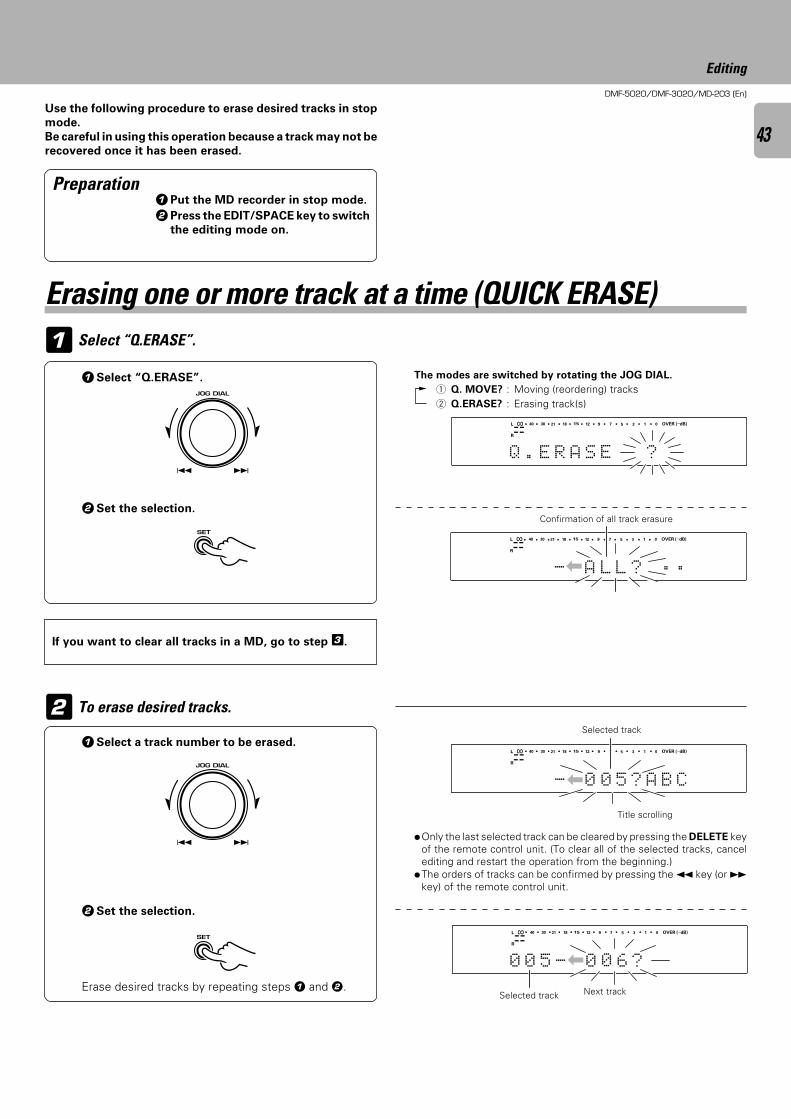
DMF-5020/DMF-3020/MD-203 (En)
43
Editing
Use the following procedure to erase desired tracks in stop
mode.
Be careful in using this operation because a track may not be
recovered once it has been erased.
1 Select “Q.ERASE”.
1Select “Q.ERASE”.
2Set the selection.
To erase desired tracks.
If you want to clear all tracks in a MD, go to step 3.
Selected track
Erase desired tracks by repeating steps 1 and 2.
Title scrolling
Next track
Preparation1Put the MD recorder in stop mode.
2Press the EDIT/SPACE key to switch
the editing mode on.
Erasing one or more track at a time (QUICK ERASE)
The modes are switched by rotating the JOG DIAL.
1 Q. MOVE? : Moving (reordering) tracks2 Q.ERASE? : Erasing track(s)
Confirmation of all track erasure
1Select a track number to be erased.
2Set the selection.
Selected track
OVER (−dB)
R
L
E RQ . A S E ?
∞ 15 912 7 5 1340 30 21 18 0
SEARCHPGM
MONITOR
ANALOG
32kHz
21 3
48kHz
44.1kHz
DIGITAL
OVER (−dB)
R
L
| 5 ? B CA00-
∞ 15 912 7 5 1340 30 21 18 0
SEARCHPGM
MONITOR
ANALOG
32kHz
21 3
48kHz
44.1kHz
DIGITAL
OVER (−dB)
R
L
- 0 0 6 ?500
∞ 15 912 7 5 1340 30 21 18 0
SEARCHPGM
MONITOR
ANALOG
32kHz
21 3
48kHz
44.1kHz
DIGITAL
|
2
OVER (−dB)
R
L
L ÷ ÷ ?LA-
∞ 15 912 7 5 1340 30 21 18 0
SEARCHPGM
MONITOR
ANALOG
32kHz
21 3
48kHz
44.1kHz
DIGITAL
|
÷Only the last selected track can be cleared by pressing the DELETE keyof the remote control unit. (To clear all of the selected tracks, cancelediting and restart the operation from the beginning.)
÷The orders of tracks can be confirmed by pressing the 1 key (or ¡key) of the remote control unit.
4 ¢ JOG DIAL
4 ¢
SET
4 ¢ JOG DIAL
4 ¢
SET
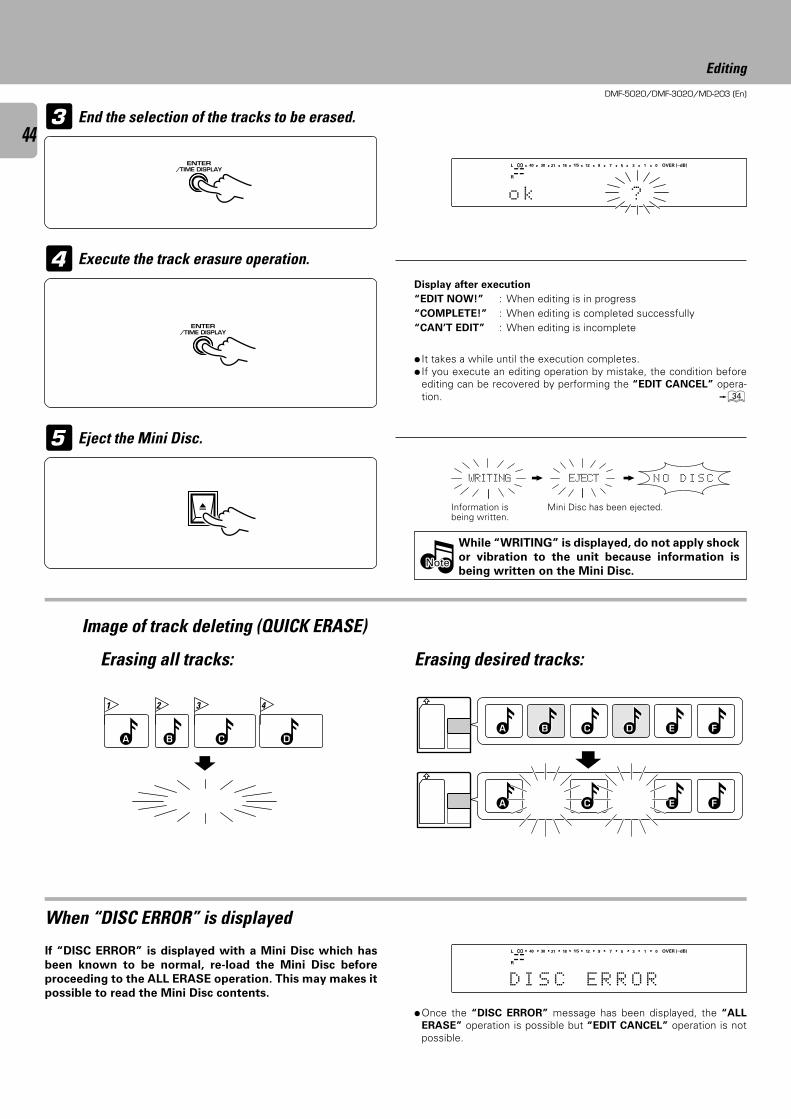
DMF-5020/DMF-3020/MD-203 (En)
44
Editing
End the selection of the tracks to be erased.3
Image of track deleting (QUICK ERASE)
While “WRITING” is displayed, do not apply shock
or vibration to the unit because information is
being written on the Mini Disc.
Execute the track erasure operation.
Eject the Mini Disc.
÷ It takes a while until the execution completes.÷ If you execute an editing operation by mistake, the condition before
editing can be recovered by performing the “EDIT CANCEL” opera-tion. ›
When “DISC ERROR” is displayed
÷Once the “DISC ERROR” message has been displayed, the “ALL
ERASE” operation is possible but “EDIT CANCEL” operation is notpossible.
If “DISC ERROR” is displayed with a Mini Disc which has
been known to be normal, re-load the Mini Disc before
proceeding to the ALL ERASE operation. This may makes it
possible to read the Mini Disc contents.
Display after execution
“EDIT NOW!” : When editing is in progress“COMPLETE!” : When editing is completed successfully“CAN’T EDIT” : When editing is incomplete
Erasing desired tracks:Erasing all tracks:
Mini Disc has been ejected.Information isbeing written.
4
5
OVER (−dB)
R
L
o k ?
∞ 15 912 7 5 1340 30 21 18 0
SEARCHPGM
MONITOR
ANALOG
32kHz
21 3
48kHz
44.1kHz
DIGITAL
N O D I S CWRITING EJECT
A B D
1 2 43
CCBA ED F
E FCA
NoteNoteNote
OVER (−dB)
R
L
D I S C E R R O R
∞ 15 912 7 5 1340 30 21 18 0
SEARCHPGM
MONITOR
ANALOG
32kHz
21 3
48kHz
44.1kHz
DIGITAL
ENTER/TIME DISPLAY
ENTER/TIME DISPLAY
0
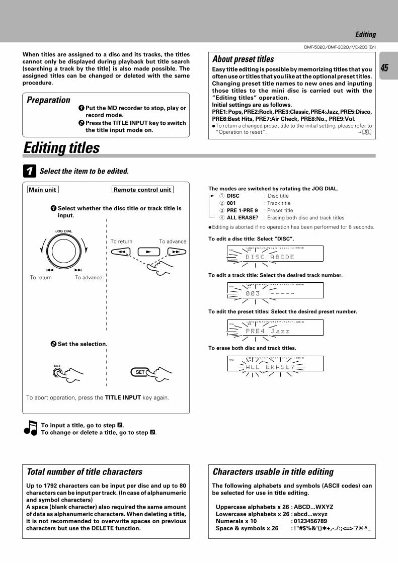
DMF-5020/DMF-3020/MD-203 (En)
45
Editing
1 Select the item to be edited.
The modes are switched by rotating the JOG DIAL.
1 DISC : Disc title2 001 : Track title3 PRE 1-PRE 9 : Preset title4 ALL ERASE? : Erasing both disc and track titles
Characters usable in title editingThe following alphabets and symbols (ASCII codes) can
be selected for use in title editing.
Uppercase alphabets x 26 : ABCD...WXYZ
Lowercase alphabets x 26 : abcd...wxyz
Numerals x 10 : 0123456789
Space & symbols x 26 : !"#$%&'()+,-./:;<=>`?@^_
When titles are assigned to a disc and its tracks, the titles
cannot only be displayed during playback but title search
(searching a track by the title) is also made possible. The
assigned titles can be changed or deleted with the same
procedure.
Total number of title charactersUp to 1792 characters can be input per disc and up to 80
characters can be input per track. (In case of alphanumeric
and symbol characters)
A space (blank character) also required the same amount
of data as alphanumeric characters. When deleting a title,
it is not recommended to overwrite spaces on previous
characters but use the DELETE function.
Preparation
1Select whether the disc title or track title is
input.
1Put the MD recorder to stop, play or
record mode.
2Press the TITLE INPUT key to switch
the title input mode on.
÷Editing is aborted if no operation has been performed for 8 seconds.
To edit a disc title: Select “DISC”.
To edit a track title: Select the desired track number.
To edit the preset titles: Select the desired preset number.
To erase both disc and track titles.2Set the selection.
To abort operation, press the TITLE INPUT key again.
To input a title, go to step 2.
To change or delete a title, go to step 3.
Editing titles
To return To advance
To return To advanceOVER (−dB)
R
L
TITLE
D I S C C D EBA
∞ 15 912 7 5 1340 30 21 18 0
SEARCHPGM
MONITOR
ANALOG
32kHz
21 3
48kHz
44.1kHz
DIGITAL
Easy title editing is possible by memorizing titles that you
often use or titles that you like at the optional preset titles.
Changing preset title names to new ones and inputing
those titles to the mini disc is carried out with the
“Editing titles” operation.
Initial settings are as follows.
PRE1: Pops, PRE2:Rock, PRE3:Classic, PRE4:Jazz, PRE5:Disco,
PRE6:Best Hits, PRE7:Air Check, PRE8:No., PRE9:Vol.÷To return a changed preset title to the initial setting, please refer to
“Operation to reset”. Q
About preset titles
Main unit Remote control unit
OVER (−dB)
R
L
TITLE
0 0 3 - - ---
∞ 15 912 7 5 1340 30 21 18 0
SEARCHPGM
MONITOR
ANALOG
32kHz
21 3
48kHz
44.1kHz
DIGITAL
OVER (−dB)
R
L
TITLE
P R E 4 z zaJ
∞ 15 912 7 5 1340 30 21 18 0
SEARCHPGM
MONITOR
ANALOG
32kHz
21 3
48kHz
44.1kHz
DIGITAL
OVER (−dB)
R
L
TITLE
A L L S E ?ARE
∞ 15 912 7 5 1340 30 21 18 0
SEARCHPGM
MONITOR
ANALOG
32kHz
21 3
48kHz
44.1kHz
DIGITAL
4 ¢ JOG DIAL
4 ¢
SET
4 ¢ £
SET
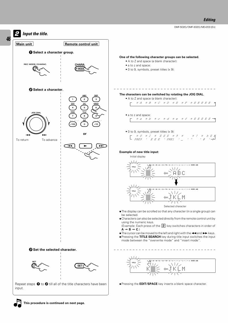
DMF-5020/DMF-3020/MD-203 (En)
46
Editing
2
The characters can be switched by rotating the JOG DIAL.
• A to Z and space (a blank character):
• a to z and space:
• 0 to 9, symbols, preset titles (x 9):
One of the following character groups can be selected.
• A to Z and space (a blank character):• a to z and space:• 0 to 9, symbols, preset titles (x 9):
Input the title.
1Select a character group.
2Select a character.
To return To advance
Example of new title input:
Initial display
÷The display can be scrolled so that any character (in a single group) canbe selected.
÷Characters can also be selected directly from the remote control unit byusing the numeric keys.(Example: Each press of the 2 key switches characters in order ofA = B = C.)
÷The cursor can be moved to the left and right with the 1 and ¡ keys.÷Pressing the TITLE SEARCH key during title input switches the input
mode between the “overwrite mode” and “insert mode”.
Selected character
This procedure is continued on next page.
3Set the selected character.
Repeat steps 1 to 3 till all of the title characters have beeninput.
÷Pressing the EDIT/SPACE key inserts a blank space character.
¤ A ¤ B ¤ C ¤ D ¤ E ¤ F ¤ E E E E E ¤
¤ a ¤ b ¤ c ¤ d ¤ e ¤ f ¤ E E E E E ¤
¤ 0 ¤ 1 ¤ E E E ¤ 9 ¤ ¤ ! ¤ h E E EPRE9 ' E E E ' PRE1 ' _ ' ^ ' @ ' ?
OVER (−dB)
R
L
TITLE
A B C|
∞ 15 912 7 5 1340 30 21 18 0
SEARCHPGM
MONITOR
ANALOG
32kHz
21 3
48kHz
44.1kHz
DIGITAL
OVER (−dB)
R
L
TITLE
J K L M|
∞ 15 912 7 5 1340 30 21 18 0
SEARCHPGM
MONITOR
ANALOG
32kHz
21 3
48kHz
44.1kHz
DIGITAL
OVER (−dB)
R
L
TITLE
J K L M|K
∞ 15 912 7 5 1340 30 21 18 0
SEARCHPGM
MONITOR
ANALOG
32kHz
21 3
48kHz
44.1kHz
DIGITAL
or
Main unit Remote control unit
CHARA.
P.MODE
1
GHI
4
PRS
7
& ( ) - /
+100
ABC
2
JKL
5
TUV
8
QZ
0
DEF
3
MNO
6
WXY
9
’ , : ? !
+10
4 ¢ £
SET
SET
4 ¢ JOG DIAL
4 ¢
REC MODE/CHARAC.
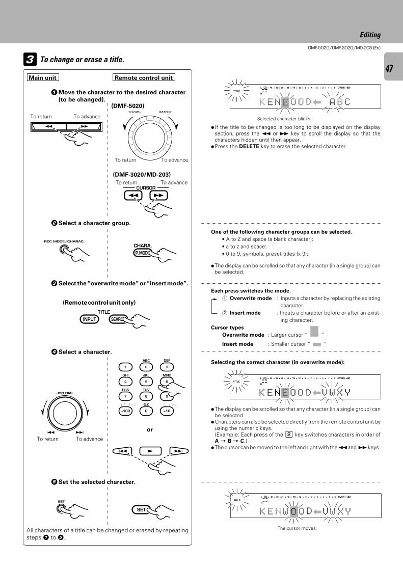
DMF-5020/DMF-3020/MD-203 (En)
47
Editing
To change or erase a title.3
One of the following character groups can be selected.
• A to Z and space (a blank character):• a to z and space:• 0 to 9, symbols, preset titles (x 9):
÷ If the title to be changed is too long to be displayed on the displaysection, press the 1 or ¡ key to scroll the display so that thecharacters hidden until then appear.
÷Press the DELETE key to erase the selected character.
3Select the “overwrite mode” or “insert mode”.
Each press switches the mode.
1 Overwrite mode : Inputs a character by replacing the existingcharacter.
2 Insert mode : Inputs a character before or after an exist-ing character.
Cursor types
Overwrite mode : Larger cursor “ ”
Insert mode : Smaller cursor “ ”
Selecting the correct character (in overwrite mode):
1Move the character to the desired character
(to be changed).
÷The display can be scrolled so that any character (in a single group) canbe selected.
2Select a character group.
4Select a character.
5Set the selected character.
÷The display can be scrolled so that any character (in a single group) canbe selected.
÷Characters can also be selected directly from the remote control unit byusing the numeric keys.(Example: Each press of the 2 key switches characters in order ofA = B = C.)
÷The cursor can be moved to the left and right with the 1 and ¡ keys.
All characters of a title can be changed or erased by repeatingsteps 1 to 5.
To return To advance
To advanceTo return
Selected character blinks.
The cursor moves.
OVER (−dB)
R
L
TITLE
O D| B CAOK NE
∞ 15 912 7 5 1340 30 21 18 0
SEARCHPGM
MONITOR
ANALOG
32kHz
21 3
48kHz
44.1kHz
DIGITAL
E
V
OVER (−dB)
R
L
TITLE
O D| X YWOK NE
∞ 15 912 7 5 1340 30 21 18 0
SEARCHPGM
MONITOR
ANALOG
32kHz
21 3
48kHz
44.1kHz
DIGITAL
E
|V W X Y
OVER (−dB)
R
L
TITLE
O DK NE
∞ 15 912 7 5 1340 30 21 18 0
SEARCHPGM
MONITOR
ANALOG
32kHz
21 3
48kHz
44.1kHz
DIGITAL
W O
4 ¢ JOG DIAL
4 ¢
To return To advance
or
Main unit Remote control unit
1 ¡
REC MODE/CHARAC.
SET
™™/CUR.L CUR.R/££
(DMF-5020)
(DMF-3020/MD-203)
¡ 1CURSOR
To return To advance
CHARA.
P.MODE
(Remote control unit only)
INPUT SEARCHTITLE
1
GHI
4
PRS
7
& ( ) - /
+100
ABC
2
JKL
5
TUV
8
QZ
0
DEF
3
MNO
6
WXY
9
’ , : ? !
+10
4 ¢ £
SET
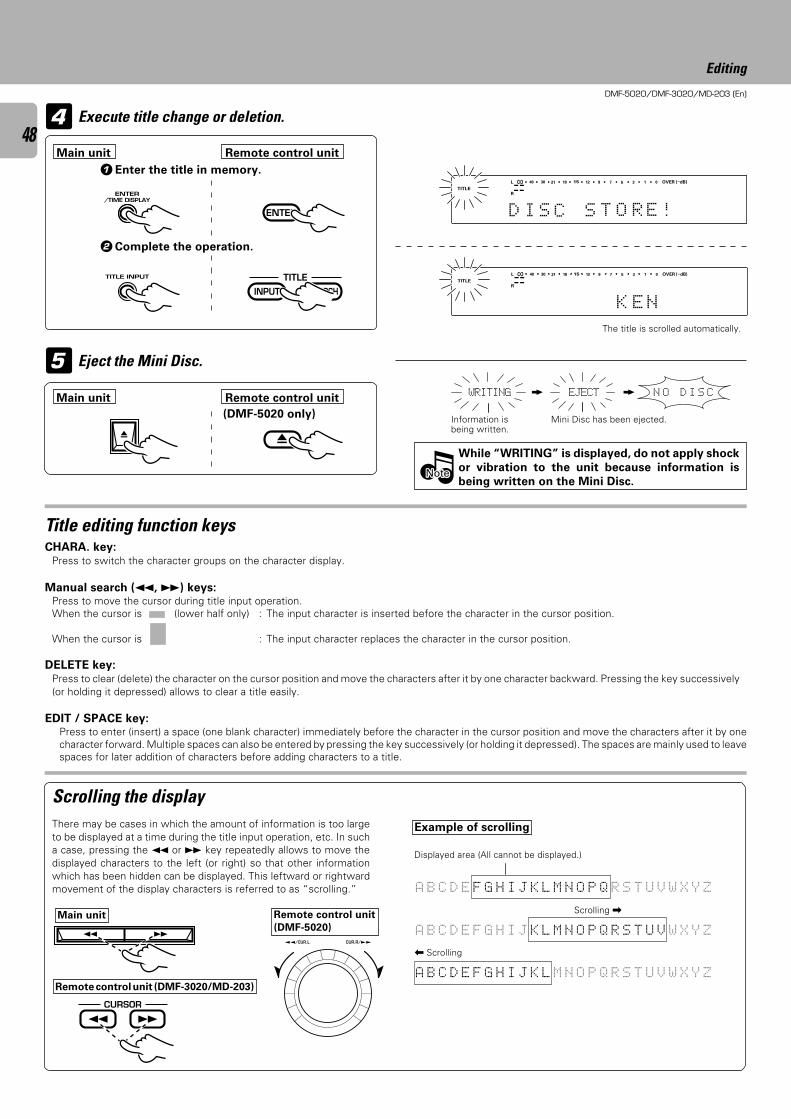
DMF-5020/DMF-3020/MD-203 (En)
48
Editing
CHARA. key:Press to switch the character groups on the character display.
Manual search (1, ¡) keys:Press to move the cursor during title input operation.When the cursor is (lower half only) : The input character is inserted before the character in the cursor position.
When the cursor is : The input character replaces the character in the cursor position.
DELETE key:Press to clear (delete) the character on the cursor position and move the characters after it by one character backward. Pressing the key successively(or holding it depressed) allows to clear a title easily.
EDIT / SPACE key:Press to enter (insert) a space (one blank character) immediately before the character in the cursor position and move the characters after it by onecharacter forward. Multiple spaces can also be entered by pressing the key successively (or holding it depressed). The spaces are mainly used to leavespaces for later addition of characters before adding characters to a title.
4
5 Eject the Mini Disc.
Execute title change or deletion.
While “WRITING” is displayed, do not apply shock
or vibration to the unit because information is
being written on the Mini Disc.
Scrolling the displayThere may be cases in which the amount of information is too largeto be displayed at a time during the title input operation, etc. In sucha case, pressing the 1 or ¡ key repeatedly allows to move thedisplayed characters to the left (or right) so that other informationwhich has been hidden can be displayed. This leftward or rightwardmovement of the display characters is referred to as “scrolling.”
Example of scrolling
Displayed area (All cannot be displayed.)
1Enter the title in memory.
The title is scrolled automatically.
2Complete the operation.
Information isbeing written.
Mini Disc has been ejected.
Title editing function keys
Main unitScrolling \
| Scrolling
N O D I S CWRITING EJECT
A B C D E F G H I J K L M N O P Q R S T U V W X Y Z
A B C D E F G H I J K L M N O P Q R S T U V W X Y Z
A B C D E F G H I J K L M N O P Q R S T U V W X Y Z
NoteNoteNote
K E N
OVER (−dB)
R
L
TITLE∞ 15 912 7 5 1340 30 21 18 0
SEARCHPGM
MONITOR
ANALOG
32kHz
21 3
48kHz
44.1kHz
DIGITAL
O R E !
OVER (−dB)
R
L
TITLE
S TD SI
∞ 15 912 7 5 1340 30 21 18 0
SEARCHPGM
MONITOR
ANALOG
32kHz
21 3
48kHz
44.1kHz
DIGITAL
C
Main unit Remote control unit
Main unit Remote control unit
ENTER
INPUT SEARCHTITLE
0
(DMF-5020 only)
™™/CUR.L CUR.R/££
¡ 1CURSOR
1 ¡
0
TITLE INPUT
ENTER/TIME DISPLAY
Remote control unit
(DMF-5020)
Remote control unit (DMF-3020/MD-203)
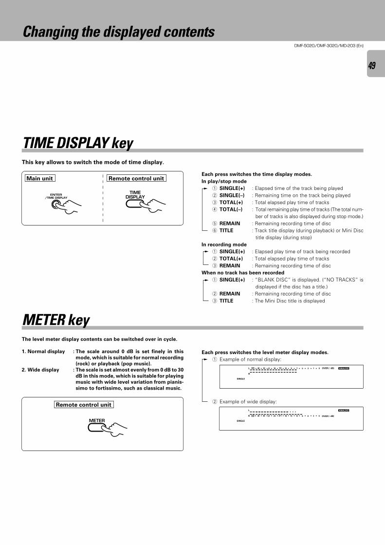
DMF-5020/DMF-3020/MD-203 (En)
49
Changing the displayed contents
This key allows to switch the mode of time display.
Each press switches the time display modes.
In play/stop mode
1 SINGLE(+) : Elapsed time of the track being played2 SINGLE(–) : Remaining time on the track being played3 TOTAL(+) : Total elapsed play time of tracks4 TOTAL(–) : Total remaining play time of tracks (The total num-
ber of tracks is also displayed during stop mode.)5 REMAIN : Remaining recording time of disc6 TITLE : Track title display (during playback) or Mini Disc
title display (during stop)In recording mode
1 SINGLE(+) : Elapsed play time of track being recorded2 TOTAL(+) : Total elapsed play time of tracks3 REMAIN : Remaining recording time of disc
When no track has been recorded
1 SINGLE(+) : “BLANK DISC” is displayed. (“NO TRACKS” isdisplayed if the disc has a title.)
2 REMAIN : Remaining recording time of disc3 TITLE : The Mini Disc title is displayed
The level meter display contents can be switched over in cycle.
1. Normal display : The scale around 0 dB is set finely in this
mode, which is suitable for normal recording
(rock) or playback (pop music).
2. Wide display : The scale is set almost evenly from 0 dB to 30
dB in this mode, which is suitable for playing
music with wide level variation from pianis-
simo to fortissimo, such as classical music.
METER key
TIME DISPLAY key
Each press switches the level meter display modes.
1 Example of normal display:
2 Example of wide display:
OVER
OVER (−dB)
(−dB)R
L
SINGLE
∞∞
15 912 7 5 1340 30 21 18 0
21 1518 12 9 3640 30 27 24 0SEARCHPGM
MONITOR
ANALOG
32kHz
21 3
48kHz
44.1kHz
DIGITAL
OVER (−dB)
R
L
SINGLE
∞ 15 912 7 5 1340 30 21 18 0
SEARCHPGM
MONITOR
ANALOG
32kHz
21 3
48kHz
44.1kHz
DIGITAL
Main unit Remote control unit
Remote control unit
ENTER/TIME DISPLAY
TIMEDISPLAY
METER
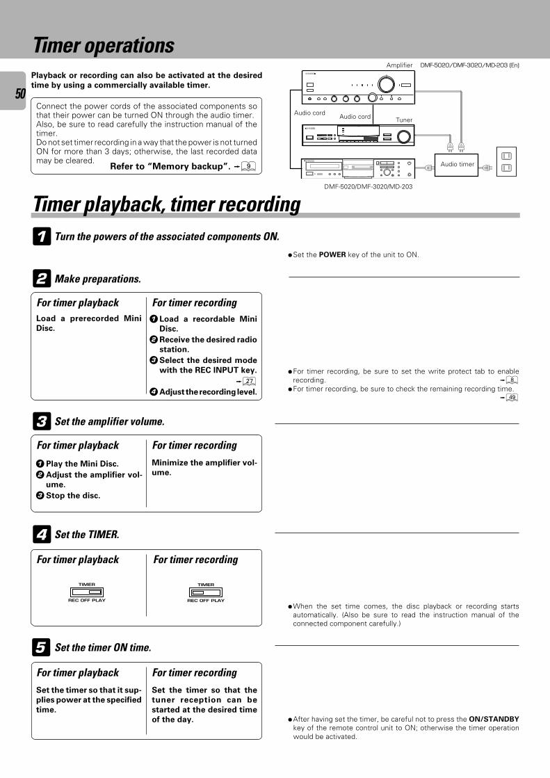
DMF-5020/DMF-3020/MD-203 (En)
50
Timer operations
1 Turn the powers of the associated components ON.
Playback or recording can also be activated at the desired
time by using a commercially available timer.
Audio timer
Connect the power cords of the associated components sothat their power can be turned ON through the audio timer.Also, be sure to read carefully the instruction manual of thetimer.Do not set timer recording in a way that the power is not turnedON for more than 3 days; otherwise, the last recorded datamay be cleared.
Tuner
Amplifier
Audio cord
DMF-5020/DMF-3020/MD-203
Audio cord
Timer playback, timer recording
÷Set the POWER key of the unit to ON.
For timer playback1Load a recordable Mini
Disc.
2Receive the desired radio
station.
3Select the desired mode
with the REC INPUT key.
¶4Adjust the recording level.
Make preparations.
÷For timer recording, be sure to set the write protect tab to enablerecording. 8
÷For timer recording, be sure to check the remaining recording time.o
2
5
÷After having set the timer, be careful not to press the ON/STANDBY
key of the remote control unit to ON; otherwise the timer operationwould be activated.
Set the timer so that the
tuner reception can be
started at the desired time
of the day.
Set the timer so that it sup-
plies power at the specified
time.
Set the timer ON time.
4For timer recording
Set the TIMER.
÷When the set time comes, the disc playback or recording startsautomatically. (Also be sure to read the instruction manual of theconnected component carefully.)
1Play the Mini Disc.
2Adjust the amplifier vol-
ume.
3Stop the disc.
Minimize the amplifier vol-
ume.
3 Set the amplifier volume.
Refer to “Memory backup”. 9
Load a prerecorded Mini
Disc.
For timer recording
For timer playback For timer recording
For timer playback
For timer playback For timer recording
TIMER
REC OFF PLAY
TIMER
REC OFF PLAY
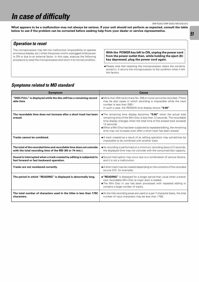
DMF-5020/DMF-3020/MD-203 (En)
51
In case of difficultyWhat appears to be a malfunction may not always be serious. If your unit should not perform as expected, consult the table
below to see if the problem can be corrected before seeking help from your dealer or service representative.
Operation to resetThe microprocessor may fall into malfunction (impossibility to operateerroneous display, etc.) when the power cord is unplugged while poweris ON or due to an external factor. In this case, execute the followingprocedure to reset the microprocessor and return it to normal condition.
With the POWER key left to ON, unplug the power cord
from the power outlet then, while holding the eject (0)
key depressed, plug the power cord again.
Symptom
÷More than 255 tracks (track No. 256 or more) cannot be recorded. (Theremay be also cases in which recording is impossible while the tracknumber is less than 256.)In such a case, the REMAIN time display shows “0:00”.
÷The remaining time display becomes “0:00” when the actual totalremaining time of the Mini Disc is less than 12 seconds. The recordabletime display changes when the total time of the erased track exceeds12 seconds.
÷When a Mini Disc has been subjected to repeated editing, the remainingtime may not increase even after a short track has been erased.
÷A track created as a result of an editing operation may sometimes beimpossible to be combined with another track.
÷As recording is performed on a minimum recording basis of 2 seconds,the displayed time may not coincide with the consumed disc capacity.
÷Sound interruption may occur due to a combination of various factors,and it is not a malfunction.
÷A short track may be created depending on the contents of the recordedsource (CD, for example).
÷“READING” is displayed for a longer period than usual when a brand-new recordable Mini Disc (a virgin disc) is loaded.
÷The Mini Disc in use has been processed with repeated editing orcontains a large number of tracks.
÷As the title recording areas are used on a per-7-character basis, the totalnumber of input characters may be less than 1792.
Cause
÷Please note that resetting the microprocessor clears the contentsstored in, it returns the microprocessor to the condition when it leftthe factory.
Symptoms related to MD standard
“DISC FULL” is displayed while the disc still has a remaining record-
able time.
The recordable time does not increase after a short track has been
erased.
Tracks cannot be combined.
The total of the recorded time and recordable time does not coincide
with the total recording time of the MD (60 or 74 min.).
Sound is interrupted when a track created by editing is subjected to
fast forward or fast backward operation.
Tracks are not numbered correctly.
The period in which “READING” is displayed is abnormally long.
The total number of characters used in the titles is less than 1792
characters.
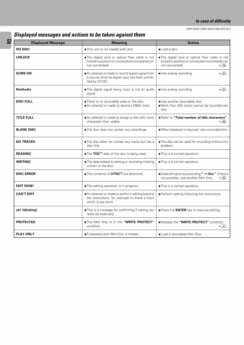
DMF-5020/DMF-3020/MD-203 (En)
52 ActionMeaningDisplayed Message
NO DISC
UNLOCK
SCMS ON
NotAudio
DISC FULL
TITLE FULL
BLANK DISC
NO TRACKS
READING
WRITING
DISC ERROR
EDIT NOW!
CAN’T EDIT
ok? (blinking)
PROTECTED
PLAY ONLY
Displayed messages and actions to be taken against them
÷Load a disc.
÷The digital cord or optical fiber cable is notlocked in position or connected incompletely (ornot connected). 0
÷Use analog recording. ¶
÷Use analog recording. ¶
÷Use another recordable disc.÷More than 255 tracks cannot be recorded per
disc.
÷Refer to ”Total number of title characters”.t
÷When playback is required, use a recorded disc.
÷The disc can be used for recording without anyproblem.
÷This is a normal operation.
÷This is a normal operation.
÷Erase all tracks by executing ”_+ALL”. If this isnot possible, use another Mini Disc. e
÷This is a normal operation.
÷Perform editing following the restrictions.
÷Press the ENTER key to execute editing.
÷Release the “WRITE PROTECT” condition.8
÷Load a recordable Mini Disc.
÷This unit is not loaded with disc.
÷The digital cord or optical fiber cable is notlocked in position or connected incompletely (ornot connected).
÷An attempt is made to record digital signal froma source while its digital copy has been prohib-ited by SCMS.
÷The digital signal being input is not an audiosignal.
÷There is no recordable area on the disc.÷An attempt is made to record a 256th track.
÷An attempt is made to assign a title with morecharacters than usable.
÷The disc does not contain any recordings.
÷The disc does not contain any tracks but has adisc title.
÷The TOC*1 data of the disc is being read.
÷The data related to editing or recording is beingwritten in the disc.
÷The contents of UTOC*2 are abnormal.
÷The editing operation is in progress.
÷An attempt is made to perform editing beyondthe restrictions, for example to erase a trackwhich is too short.
÷This is a message for confirming if editing canreally be executed.
÷The Mini Disc is in the “WRITE PROTECT”
condition.
÷A playback-only Mini Disc is loaded.
In case of difficulty
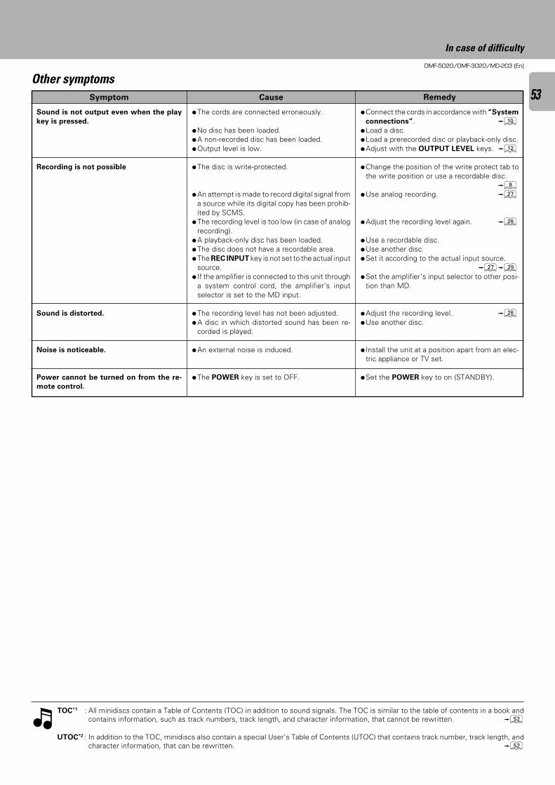
DMF-5020/DMF-3020/MD-203 (En)
53RemedyCauseSymptom
TOC*1 : All minidiscs contain a Table of Contents (TOC) in addition to sound signals. The TOC is similar to the table of contents in a book andcontains information, such as track numbers, track length, and character information, that cannot be rewritten. W
UTOC*2 : In addition to the TOC, minidiscs also contain a special User’s Table of Contents (UTOC) that contains track number, track length, andcharacter information, that can be rewritten. W
Other symptoms
Sound is not output even when the play
key is pressed.
Recording is not possible
Sound is distorted.
Noise is noticeable.
Power cannot be turned on from the re-
mote control.
÷The cords are connected erroneously.
÷No disc has been loaded.÷A non-recorded disc has been loaded.÷Output level is low.
÷The disc is write-protected.
÷An attempt is made to record digital signal froma source while its digital copy has been prohib-ited by SCMS.
÷The recording level is too low (in case of analogrecording).
÷A playback-only disc has been loaded.÷The disc does not have a recordable area.÷The REC INPUT key is not set to the actual input
source.÷ If the amplifier is connected to this unit through
a system control cord, the amplifier’s inputselector is set to the MD input.
÷The recording level has not been adjusted.÷A disc in which distorted sound has been re-
corded is played.
÷An external noise is induced.
÷The POWER key is set to OFF.
÷Connect the cords in accordance with “System
connections”. 0÷Load a disc.÷Load a prerecorded disc or playback-only disc.÷Adjust with the OUTPUT LEVEL keys. @
÷Change the position of the write protect tab tothe write position or use a recordable disc.
8÷Use analog recording. ¶
÷Adjust the recording level again. •
÷Use a recordable disc.÷Use another disc.÷Set it according to the actual input source.
¶ª÷Set the amplifier’s input selector to other posi-
tion than MD.
÷Adjust the recording level. •÷Use another disc.
÷ Install the unit at a position apart from an elec-tric appliance or TV set.
÷Set the POWER key to on (STANDBY).
In case of difficulty
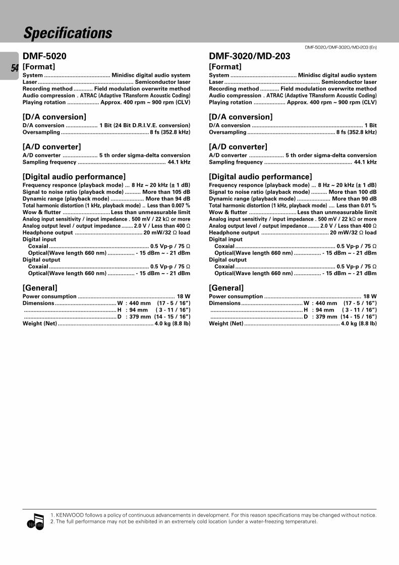
DMF-5020/DMF-3020/MD-203 (En)
54
SpecificationsDMF-5020[Format]System .......................................... Minidisc digital audio system
Laser ............................................................. Semiconductor laser
Recording method ............ Field modulation overwrite method
Audio compression . ATRAC (Adaptive TRansform Acoustic Coding)
Playing rotation .................... Approx. 400 rpm ~ 900 rpm (CLV)
[D/A conversion]D/A conversion .................... 1 Bit (24 Bit D.R.I.V.E. conversion)
Oversampling ........................................................ 8 fs (352.8 kHz)
[A/D converter]A/D converter ...................... 5 th order sigma-delta conversion
Sampling frequency ........................................................ 44.1 kHz
[Digital audio performance]Frequency responce (playback mode) ... 8 Hz ~ 20 kHz (± 1 dB)
Signal to noise ratio (playback mode) .......... More than 105 dB
Dynamic range (playback mode) ..................... More than 94 dB
Total harmonic distortion (1 kHz, playback mode) .. Less than 0.007 %
Wow & flutter .............................. Less than unmeasurable limit
Analog input sensitivity / input impedance . 500 mV / 22 kΩ or more
Analog output level / output impedance ........ 2.0 V / Less than 400 ΩHeadphone output ........................................... 20 mW/32 Ω load
Digital input
Coxaial ................................................................ 0.5 Vp-p / 75 ΩOptical(Wave length 660 nm) ................. - 15 dBm ~ - 21 dBm
Digital output
Coxaial ................................................................ 0.5 Vp-p / 75 ΩOptical(Wave length 660 nm) ................. - 15 dBm ~ - 21 dBm
[General]Power consumption .............................................................. 18 W
Dimensions ....................................... W : 440 mm (17 - 5 / 16”)
........................................................... H : 94 mm ( 3 - 11 / 16”)
........................................................... D : 379 mm (14 - 15 / 16”)
Weight (Net) ............................................................. 4.0 kg (8.8 lb)
1. KENWOOD follows a policy of continuous advancements in development. For this reason specifications may be changed without notice.2. The full performance may not be exhibited in an extremely cold location (under a water-freezing temperature).
NotesNotes
DMF-3020/MD-203[Format]System .......................................... Minidisc digital audio system
Laser ............................................................. Semiconductor laser
Recording method ............ Field modulation overwrite method
Audio compression . ATRAC (Adaptive TRansform Acoustic Coding)
Playing rotation .................... Approx. 400 rpm ~ 900 rpm (CLV)
[D/A conversion]D/A conversion ....................................................................... 1 Bit
Oversampling ........................................................ 8 fs (352.8 kHz)
[A/D converter]A/D converter ...................... 5 th order sigma-delta conversion
Sampling frequency ........................................................ 44.1 kHz
[Digital audio performance]Frequency responce (playback mode) ... 8 Hz ~ 20 kHz (± 1 dB)
Signal to noise ratio (playback mode) .......... More than 100 dB
Dynamic range (playback mode) ..................... More than 90 dB
Total harmonic distortion (1 kHz, playback mode) .... Less than 0.01 %
Wow & flutter .............................. Less than unmeasurable limit
Analog input sensitivity / input impedance . 500 mV / 22 kΩ or more
Analog output level / output impedance ........ 2.0 V / Less than 400 ΩHeadphone output ........................................... 20 mW/32 Ω load
Digital input
Coxaial ................................................................ 0.5 Vp-p / 75 ΩOptical(Wave length 660 nm) ................. - 15 dBm ~ - 21 dBm
Digital output
Coxaial ................................................................ 0.5 Vp-p / 75 ΩOptical(Wave length 660 nm) ................. - 15 dBm ~ - 21 dBm
[General]Power consumption .............................................................. 18 W
Dimensions ....................................... W : 440 mm (17 - 5 / 16”)
........................................................... H : 94 mm ( 3 - 11 / 16”)
........................................................... D : 379 mm (14 - 15 / 16”)
Weight (Net) ............................................................. 4.0 kg (8.8 lb)
DMF-5020/DMF-3020/MD-203 (En)
55For the U.S.A.
KENWOOD CORP. CERTIFIES THIS EQUIPMENT
CONFORMS TO DHHS REGULATIONS NO. 21
CFR 1040.10, CHAPTER 1, SUBCHAPTER J.
For the U.S.A.
Location: Back Panel
FCC WARNINGThis equipment may generate or use radio frequency energy. Changes or modifications to this equipment may cause harmful interference unlessthe modifications are expressly approved in the instruction manual. The user could lose the authority to operate this equipment if an unauthorizedchange or modification is made.
NOTE:This equipment has been tested and found to comply with the limits for a Class B digital device, pursuant to Part 15 of the FCC Rules. These limitsare designed to provide reasonable protection against harmful interference in a residential installation. This equipment may cause harmfulinterference to radio communications, if it is not installed and used in accordance with the instructions. However, there is no guarantee thatinterference will not occur in a particular installation. If this equipment does cause harmful interference to radio or television reception, which canbe determined by turning the equipment off and on, the user is encouraged to try to correct the interference by one or more of the following measures:– – Reorient or relocate the receiving antenna.– – Increase the separation between the equipment and receiver.– – Connect the equipment into an outlet on a circuit different from that to which the receiver is connected.– – Consult the dealer or an experienced radio/TV technician for help.
CAUTION :Use of controls or adjustment or performance of procedures
other than those specified herein may result in hazardous radia-
tion exposure.
In compliance with Federal Regulations, following are reproduc-
tions of labels on, or inside the product relating to laser product
safety.
KENWOOD CORPORATION
2967-3, ISHIKAWA-CHO, HACHIOJI-SHI,
TOKYO,JAPAN

For your recordsRecord the serial number, found on the back of the unit, in the spacesdesignated on the warranty card, and in the space provided below. Referto the model and serial numbers whenever you call upon your dealer forinformation or service on this product.
Model Serial Number