stratford water pollution control plant … · structural rehabilitation for the stratford water...
TRANSCRIPT

Stratford Water Pollution Control Plant Clarifier Upgrades and Structural Rehabilitation
Contract 16-9725
CITY OF STRATFORD
INFRASTRUCTURE & DEVELOPMENT SERVICES DEPARTMENT
FOR REFERENCE O
NLY
NOT OFFIC
IAL B
ID D
OCUMENT

FOR REFERENCE O
NLY
NOT OFFIC
IAL B
ID D
OCUMENT

BIDDER’S CHECK LIST Before submitting your tender, check to ensure the following has all been completed:
1. Have you purchased the Bid Documents at City of Stratford’s Engineering Division? ( )
2. Has your tender been signed in ink, sealed and witnessed? ( )
3. Have you enclosed the Tender Deposit, i.e. certified cheque or bid bond? (whichever, is required by the Contract Documents). ( )
4. Have you enclosed the Agreement to Bond, signed and sealed by your proposed Surety? ( )
5. Have you completed all schedules and prices in the Form of Tender? ( )
6. Have you indicated the number of addenda included in the Tender Price? ( )
7. Have you listed your Sub-Contractors? (if applicable) ( )
8. Have you listed your Experience in Similar Work? (if applicable) ( )
9. Have you listed your Senior Staff? (if applicable) ( )
10. Are the documents complete? ( )
FOR REFERENCE O
NLY
NOT OFFIC
IAL B
ID D
OCUMENT

FOR REFERENCE O
NLY
NOT OFFIC
IAL B
ID D
OCUMENT

LIST OF CONTRACT DOCUMENTS
Section No. Description Addendum Numbered __ to __
Bidder’s Check List Emergency/Contacts List List of Drawings
1. Information to Tenderers 2. Form of Tender
Contingency Allowance Proof of Contractor Ability List of Alternatives or Equivalents Tenderer’s Senior Staff
Tenderer’s Plant and Equipment List of Sub-Contractors and Suppliers Agreement to Bond
3. Contract for Works
4. Special Provisions: Not Applicable
5. Supplemental Specifications: Division 1 to 16 6. Process Control Narrative
NOTE: Ontario Provincial Standards Specifications (OPSS) and the City of Stratford’s Infrastructure Standards and Specifications (ISS)1 are not bound with these documents. Any reference to these Standard Specifications and Drawings is the most recent revision thereof. The Infrastructure Standards and Specifications Standard Drawings (SD) can be found at the above link.
1 https://www.stratfordcanada.ca/en/insidecityhall/infrastructuredevelopment.asp
FOR REFERENCE O
NLY
NOT OFFIC
IAL B
ID D
OCUMENT

FOR REFERENCE O
NLY
NOT OFFIC
IAL B
ID D
OCUMENT

EMERGENCY/CONTACTS LIST
EMERGENCY NUMBER 911
POISON INFORMATION CENTRE 1-800-268-9017 ENVIRONMENTAL SPILL REPORTING 1-800-268-6060 UPPER THAMES RIVER CONSERVATION AUTHORITY 1-519-451-2800
EMERGENCY SERVICES (Office Calls)
AMBULANCE SERVICES 1-800-265-1868 STRATFORD POLICE SERVICES 519-271-4143 STRATFORD FIRE DEPARTMENT 519-271-3213 STRATFORD GENERAL HOSPITAL 519-271-2120
UTILITIES/LOCATE INFORMATION
ONTARIO ONE CALL 1-800-400-2255 BELL CANADA
UNION GAS FESTIVAL HYDRO
ROGERS CABLE TV MORNINGTON COMMUNICATIONS QUADRO COMMUNICATIONS WIGHTMAN TELECOM
HYDRO ONE (Call Centre) 1-888-664-9376 WATER POLLUTION CONTROL PLANT (OCWA) 519-271-9071
CITY OF STRATFORD
INFRASTRUCTURE & DEVELOPMENT SERVICES 519-271-0250 ext. 222 PUBLIC WORKS DIVISION AFTER HOURS 519-271-0820 WATER DIVISION AFTER HOURS 519-271-4700
FOR REFERENCE O
NLY
NOT OFFIC
IAL B
ID D
OCUMENT

FOR REFERENCE O
NLY
NOT OFFIC
IAL B
ID D
OCUMENT

LIST OF DRAWINGS
DWG No. Sheet Name
G00 Title Page
G01 Abbreviations
R001 Removals 1
R002 Removals 2
R003 Removals 3
C101 Site Plan
S001 General Notes
S002 Clarifier Modifications
S003 Clarifier Valve Chamber
S004 Distribution Chamber
S005 Miscellaneous Details
S006 Miscellaneous Details
P001 Hydraulic Profile
P201 General Arrangement
P202 Clarifier Section & Distribution Chamber
P203 Existing Primary Clarifier Valve Chamber
P204 Process Flow Diagram
I001 PLC Control Panel ICP-B Retrofit
I002 ICP-B Control Panel Power Distribution
I003 Analog Input PLC Rack 0 Slot 08
I004 New Digital Input PLC Rack 0 Slot 09
I005 New Digital Output PLC Rack 1 Slot 03
E001 Electrical Site Plan and Layout
E002 Single Line Diagram
FOR REFERENCE O
NLY
NOT OFFIC
IAL B
ID D
OCUMENT

FOR REFERENCE O
NLY
NOT OFFIC
IAL B
ID D
OCUMENT

SECTION NO. 1
INFORMATION FOR TENDERERS
Stratford WPCP Clarifier Upgrades and Structural Rehabilitation Contract 16-9725
CITY OF STRATFORD
INFRASTRUCTURE & DEVELOPMENT SERVICES DEPARTMENT
FOR REFERENCE O
NLY
NOT OFFIC
IAL B
ID D
OCUMENT

FOR REFERENCE O
NLY
NOT OFFIC
IAL B
ID D
OCUMENT

TABLE OF CONTENTS
1. TENDER REQUIREMENT SUMMARY .......................................................................... 1
2. SCOPE OF WORK .............................................................................................................. 1
3. CORPORATION’S REPRESENTITIVES ......................................................................... 2
4. EXAMINATION OF SITE.................................................................................................. 2
5. PRE-BID MEETING ........................................................................................................... 2
6. DELIVERY AND OPENING OF TENDERS .................................................................... 2
7. INTERPRETATIONS AND ADDENDA ........................................................................... 3
8. OMISSIONS AND DISCREPANCIES .............................................................................. 3
9. DISQUALIFICATION OF TENDERS ............................................................................... 3
10. WITHDRAWAL OF TENDERS ........................................................................................ 3
11. INFORMAL OR UNBALANCED TENDERS .................................................................. 4
12. TENDER DEPOSIT ............................................................................................................ 4
13. ACCEPTANCE OR REJECTION OF TENDERS ............................................................. 5
14. QUALIFICATION OF TENDERERS ................................................................................ 5
15. CONDITIONS PRECEDENT TO AWARD....................................................................... 6
16. EXECUTION OF AGREEMENT ....................................................................................... 6
17. CONSTRUCTION PERIOD ............................................................................................... 8
18. SUB-CONTRACTORS ....................................................................................................... 8
19. SALES TAX, FEDERAL AND PROVINCIAL ................................................................. 8
20. PAYMENTS, MAINTENANCE AND HOLDBACKS ..................................................... 8
21. LIQUIDATED DAMAGES .............................................................................................. 10
22. WORKPLACE SAFETY AND INSURANCE BOARD .................................................. 10
23. OCCUPATIONAL HEALTH & SAFETY ....................................................................... 10
24. MUNICIPAL FREEDOM OF INFORMATION & PROTECTION OF PRIVACY ACT11
25. COMPLIANCE WITH AODA ACCESSIBITY STANDARDS ...................................... 11
26. WORKING HOURS & HOLIDAYS ................................................................................ 12
27. GEOTECHNICAL INVESTIGATION ............................................................................. 12
28. ENVIRONMENTAL PROTECTION ............................................................................... 12
29. PROVISIONAL ITEMS .................................................................................................... 13
30. TESTING ALLOWANCE................................................................................................. 13
FOR REFERENCE O
NLY
NOT OFFIC
IAL B
ID D
OCUMENT

FOR REFERENCE O
NLY
NOT OFFIC
IAL B
ID D
OCUMENT

Stratford WPCP Clarifier Upgrades and Structural Rehabilitation Section 1 - Information to Tenderers Contract 16-9725 Page 1
1. TENDER REQUIREMENT SUMMARY
Contract Name: Stratford WPCP Clarifier Upgrades and Structural Rehabilitation
Contract Number: Contract 16-9725 Tender Closing Date: June 15, 2016 Corporation: City of Stratford Address: City Hall, 1 Wellington Street Stratford, Ontario N5A 6W1 Bid Deposit: $500,000 Validity: 90 days Bonding: Performance: 100% Labour and Material Payment: 100%
Maintenance Term: One Year Insurance: Commercial General Liability: $5,000,000.00 Non-owned Automobile: $2,000,000.00 Automobile Third Party: $2,000,000.00 Environmental Impairment Liability: Not Applicable Cancellation Notice: 30 days SPECIAL NOTES: The Corporation of the City of Stratford, and CIMA Canada Inc. are to be added as additional insured(s).
2. SCOPE OF WORK
The work under this contract generally consists of the primary clarifier upgrades and structural rehabilitation for the Stratford Water Pollution Control Plant from Construction Limits. The clarifier upgrades and structural rehabilitation activities primarily relate to replacement of two (2) primary clarifier mechanism, structural refurbishment of upper walls of all four (4) primary clarifiers and modifications of sludge/scum piping system.
FOR REFERENCE O
NLY
NOT OFFIC
IAL B
ID D
OCUMENT

Stratford WPCP Clarifier Upgrades and Structural Rehabilitation Section 1 - Information to Tenderers Contract 16-9725 Page 2
Anticipated Project Schedule:
Tender Pickup: May 16, 2016 Bidders Meeting: May 25, 2016 Tender Close: June 15, 2016 Council Award: June 27, 2016 Pre-Construction Meeting: To be scheduled after tender close Construction Start: July 18, 2016 Working Days: 270 Working Days
3. CORPORATION’S REPRESENTITIVES
City of Stratford Representative: Mike Mortimer Manager of Environmental Services Infrastructure and Development Services Telephone: 519-271-0250 ext. 315 Email: [email protected]
4. EXAMINATION OF SITE Each Tenderer must visit the site of the work before submitting his tender and must satisfy himself by personal examination as to the local conditions to be met with during the construction and conduct of the work. He shall make his own estimate of the facilities and difficulties to be encountered including the nature of the subsurface materials and conditions. The Contractor shall not make claim at any time after tender that there was any misunderstanding of the terms and conditions of the contract relating to site conditions.
5. PRE-BID MEETING
A Bidders meeting will be held on May 25, 2016 at Stratford WPCP 701 West Gore Street, Stratford. Failure to attend the Bidders Meeting may impact selection and contribute to disqualification.
6. DELIVERY AND OPENING OF TENDERS
Sealed tenders clearly marked:
“Stratford WPCP Clarifier Upgrades and Structural Rehabilitation” Contract 16-9725
will be received by: Purchasing Department
City Hall P.O. Box 818 1 Wellington Street Stratford ON N5A 2L3
FOR REFERENCE O
NLY
NOT OFFIC
IAL B
ID D
OCUMENT

Stratford WPCP Clarifier Upgrades and Structural Rehabilitation Section 1 - Information to Tenderers Contract 16-9725 Page 3
until 2:00:00 p.m. LOCAL TIME on June 15, 2016. Upon receipt of the tender, it shall be marked with the time and date of its receipt by the Corporation. Tenders will be opened, read and recorded on June 15, 2016 at 2:15 p.m. LOCAL TIME.
7. INTERPRETATIONS AND ADDENDA No oral interpretation shall be made to a Tenderer as to the meaning of any of the contract documents, or be effective to modify any of the provisions of the contract documents. Every request for an interpretation shall be made in writing, addressed and forwarded to the Engineer. No addendum(s) will be issued within 48 hours prior to bid closing. All addendum(s) become part of the documents and must be acknowledged and/or submitted as instructed with the bid. All addendum(s) will be posted on the City of Stratford website; Bid Opportunities2 . It is the Tenderer’s sole responsibility to check the website for addendum(s) prior to submitting their bid. Any bid received without addendum(s) acknowledged and/or submitted as instructed will be rejected.
8. OMISSIONS AND DISCREPANCIES Should a Tenderer find discrepancies, or omissions from, the drawings or contract documents, or should he be in doubt as to their meaning, he should notify the Engineer who may send a written instruction to all Tenderers.
9. DISQUALIFICATION OF TENDERS Under no circumstances will tenders be considered which:
(a) are received after the closing time stated under Delivery and Opening of Tenders;
(b) are not accompanied by a certified cheque/bank draft/letter of credit/bid bond in the amounts specified.
10. WITHDRAWAL OF TENDERS
A Tenderer who has submitted a tender may submit a further tender at any time up to the official closing time. The last tender received shall supercede and invalidate all tenders previously submitted by that Tenderer for this Contract. A Tenderer may withdraw his tender at any point up to the official closing time by letter bearing the signature of any authorized by the Tenderer.
2 https://www.stratfordcanada.ca/en/insidecityhall/bidopportunities.asp
FOR REFERENCE O
NLY
NOT OFFIC
IAL B
ID D
OCUMENT

Stratford WPCP Clarifier Upgrades and Structural Rehabilitation Section 1 - Information to Tenderers Contract 16-9725 Page 4
All withdrawn or superceded tenders will be returned unopened.
11. INFORMAL OR UNBALANCED TENDERS Tenders which are incomplete, conditional, illegible or obscure, or that contain additions not called for, reservations, erasures, alterations or irregularities of any kind, may be rejected as informal or result in automatic rejection. Tenders that contain prices, which appear to be so unbalanced as likely to affect adversely the interests of the Corporation, may be rejected. The Corporation reserves the right to waive formalities at its discretion. Wherever in a tender the amount tendered for an item does not agree with the extension of the estimated quantity and the tendered unit price, the unit price shall govern and the amount shall be corrected accordingly.
12. TENDER DEPOSIT Each tender shall be accompanied by a tender deposit in the form of a certified cheque/bank draft/letter of credit/ or bid bond, using the most current CCDC format, with 90 day validity made payable to The Corporation of the City of Stratford in the amount of $500,000. The tender deposits of all tenders except two will be returned within ten (10) business days from the date of opening tenders. The tender deposits of the two tenders will be retained until a tender has been accepted and the contract bond and the other documents required herein have been furnished to the satisfaction of the Solicitor and the Engineer for the Corporation save that if a Tenderer has not been notified that his tender has been recommended to the Corporation for acceptance within 90 days after the date of opening tenders, their tender deposit will be returned on demand and if a tender has not been accepted and an Agreement executed within 90 days after the date of opening tenders, any remaining tender deposit will be returned. After the execution of the contract and the receipt by the Corporation of the contract bond the tender deposit of the successful Tenderer will be returned. The demand for the return of a tender deposit in accordance herewith or the return of a tender deposit by the Corporation to a Tenderer whose tender has not been accepted shall constitute the withdrawal of the expiry of the validity of the tender. Except as otherwise herein provided the Tenderer guarantees that if his tender is withdrawn before the Corporation shall have considered the tenders or before or after he has been notified that his tender has been recommended to the Corporation for acceptance or that if the Corporation does not for any reason receive within the said period of seven (7) days and as required herein the Agreement executed by the Tenderer, the contract bond executed by the Tenderer and the surety company and the other documents required herein, the Corporation may retain the tender deposit for the use of the Corporation and may accept any tender, advertise for new tenders, negotiate
FOR REFERENCE O
NLY
NOT OFFIC
IAL B
ID D
OCUMENT

Stratford WPCP Clarifier Upgrades and Structural Rehabilitation Section 1 - Information to Tenderers Contract 16-9725 Page 5
a contract or not accept any tender as the Corporation may deem advisable.
13. ACCEPTANCE OR REJECTION OF TENDERS
Subject to the OPS General Conditions, neither the Engineer nor any officer or employee of the Corporation has authority to make or accept an offer or to enter into a contract on behalf of the Corporation or to create any rights against or to impose any obligations on the Corporation. Recommendation of a tender to the Corporation for acceptance does not constitute acceptance of the tender by the Corporation. A tender is accepted by the Corporation and a contract is made thereby between the Corporation and a Tenderer only when an Agreement is executed by the Corporation and by the Tenderer and the acceptance of a tender and the execution of an Agreement by the Corporation is subject to the express condition that the Corporation receive a contract bond, as required herein and in a form satisfactory to the Solicitor for the Corporation, within seven (7) days after notification of the execution of the Agreement by the Corporation has been mailed to the Tenderer whose tender has been accepted as aforesaid. The Corporation shall not be responsible for any liabilities, costs, expenses, loss or damage incurred, sustained or suffered by any Tenderer prior or subsequent to or by reason of the acceptance of a tender save as provided in the Contract. Tenders are subject to a formal contract being prepared and executed. The Corporation reserves the right to reject any or all tenders and to waive formalities as the interest of the Corporation may require without stating reasons therefore and the lowest or any tender will not necessarily be accepted. In particular, the Corporation reserves both the right to reject a tender from any person or corporation with whom the Corporation is in litigation, and the right to prevent such person or corporation from performing any supply or sub-contract function on this project. By submitting a tender, the Tenderer acknowledges that it shall have no claim against, or entitlement to damages from, the Corporation by reason of the Corporation's rejection of its bid or all bids.
14. QUALIFICATION OF TENDERERS The Corporation may make such investigations as it deems necessary to determine the ability of the Tenderer to perform the work, and the Tenderer shall furnish to the Corporation all such information and data for the purpose as the Corporation may request. The Corporation reserves the right to reject any Tender if the evidence submitted by or investigation of such Tenderer fails to satisfy the Corporation that such Tenderer is properly qualified to carry out the obligations of the Contract and to complete the work as contemplated therein.
FOR REFERENCE O
NLY
NOT OFFIC
IAL B
ID D
OCUMENT

Stratford WPCP Clarifier Upgrades and Structural Rehabilitation Section 1 - Information to Tenderers Contract 16-9725 Page 6
15. CONDITIONS PRECEDENT TO AWARD
The award and execution of the Contract itself may proceed although order to commence will not take force and effect until such time as all approvals have been confirmed. Awarding and execution of this contract is subject to City of Stratford Council, Ministry of Environment and Climate Change approval. If the order to commence by the Engineer has not been satisfied within the period for acceptance of 90 days from contract award due to approvals not being received beyond the City’s control, the Contractor will be free to extend such period, or to refuse to accept the Contract without penalty, or to negotiate revised terms with the Corporation subject to acceptance. The Contractor will save harmless the City of Stratford from any and all damages and claims notwithstanding the fact that the Corporation may have indicated an intent to execute the Contract and/or also notwithstanding the fact that, as a consequence of such indication to enter into a Contract, all relevant Contract Documents may have been supplied and/or fully executed in anticipation of such approvals.
16. EXECUTION OF AGREEMENT
The following is supplementary to the OPS General Conditions. The Tenderer agrees that if they have been notified that their tender has been recommended to the Corporation for acceptance they will execute the Agreement in duplicate in the form bound herein, including the following contract documents, within seven (7) days after being notified so to do by the Corporation or anyone acting on its behalf. (a) (i) Performance Bond
The Tenderer agrees that they will furnish a contract performance bond in the amount of 100% of the total tender price, using the most current Canadian Construction Documents Committee (CCDC) format. Such performance bond shall guarantee faithful performance of the Contract during the period of the Contract, including the period of guaranteed maintenance. One copy of the contract performance bond shall be bound into each of the two executed sets of the contract.
(ii) Labour and Material Payment Bond
This contract will require 100% Labour and Material Payment Bond. This form is to comply with the most current Canadian Construction Documents Committee (CCDC) format. One copy of the Labour and Material Payment Bond shall be attached into each of the two executed sets of the Contract.
(iii) Agreement to Bond
The Tenderer shall include with his tender the Agreement to Bond in the form enclosed herewith, executed under its corporate seal by the surety company from which he proposed to obtain the bond.
FOR REFERENCE O
NLY
NOT OFFIC
IAL B
ID D
OCUMENT

Stratford WPCP Clarifier Upgrades and Structural Rehabilitation Section 1 - Information to Tenderers Contract 16-9725 Page 7
(b) Insurance
Before commencement of the work the Contractor must furnish to The Corporation of the City of Stratford, a Certificate of Insurance (on the Certificate of Insurance form provided at the end of this section) detailing such coverage as provided under the Commercial General Liability policy, Non Owned Automobile Liability policy and Standard Owners Automobile Liability policy, Coverage shall be effected by such Insurer(s) licensed in the Province of Ontario, Canada, and/or acceptable to The Corporation of the City of Stratford. The Commercial General Liability shall be on an “Occurrence basis”. “Claims Made” and/or Comprehensive General Liability policies are not acceptable unless approved in writing by the Engineer. The policies will not be altered to the detriment of the City, cancelled or allowed to lapse without giving 30 days written notice to The Corporation of the City of Stratford and shall remain in force from Contract execution to the end of the Warranty period. The Corporation of the City of Stratford, The Ontario Clean Water Agency (OCWA) and CIMA Canada Inc. must be included as Additional Insured(s) with respect to the Commercial General Liability policy. The Contractor shall indemnify and hold harmless the Corporation of the City of Stratford, it officers and employees from and against any and all liabilities, claims, demands, loss, cost, damages, actions, suits or other proceedings by whomsoever made, directly or indirectly arising out of the project attributable to bodily injury, sickness, disease or death or to damage to or destruction of tangible property caused by acts or omissions of the Contractor, its officers, agents, servants, employees, customers, invitees or licensees, or occurring in or on the premises or any part thereof and, as a result of activities under this contract. Mandatory Coverage: (i) Commercial General Liability (IBC 2100 or its Equivalency)
Shall include the Corporation, its employees and Consultants as Insureds. The Corporation of the City of Stratford and such other entities as directed shall be added as additional Insureds. Minimum acceptable limits are $5,000,000 per Occurrence. The Commercial General Liability policy must include “Blanket Contractual Liability” and “Cross Liability” endorsements.
The policy shall not contain any exclusions with respect to: shoring, underpinning, raising or demolition of any building or structure, pile driving, caisson work, collapse (XCU) of any structure or subsidence of any property or structure, without the prior consent of the Engineer.
FOR REFERENCE O
NLY
NOT OFFIC
IAL B
ID D
OCUMENT

Stratford WPCP Clarifier Upgrades and Structural Rehabilitation Section 1 - Information to Tenderers Contract 16-9725 Page 8
Maximum Property Damage/Bodily Injury Deductible $5,000 for which the Contractor assumes full responsibility.
(ii) Non Owned Automobile Liability Policy
Minimum Limits of Liability $2,000,000 and coverage must be extended to include vehicles hired under Contract.
(iii) Standard Owners Automobile Liability Policy
Minimum Limits of Liability $2,000,000
17. CONSTRUCTION PERIOD
Construction shall start on the date of the Engineer’s written order to commence on or about July 18, 2016. The Tenderer shall complete the work within a time to be known as the “Time for Completion” of 270 Working Days.
18. SUB-CONTRACTORS
No sub-contractors, other than those listed at the time of tendering shall be permitted unless approved in writing by the Engineer. Only one sub-contractor shall be named for each part of the work to be sublet (refer to Statement ‘D’, Form of Tender). Not more than 50% of the tender amount may be sub-contracted.
19. SALES TAX, FEDERAL AND PROVINCIAL
(a) Harmonized Sales Tax The Tenderer shall show separately in the total tender pricing all applicable Harmonized Sales Tax and shall be responsible to verify with the Customs and Excise Branch of Canada Customs and Revenue Agency any rulings for payment of tax or tax exemptions.
(b) Changes to Government Taxes Where a change in Canadian Federal or Provincial taxes occurs after the tender
closing date for this contract, and this change would not have been anticipated at the time of bidding, the municipality will increase or decrease contract payments to account for the exact amount of tax change involved.
20. PAYMENTS, MAINTENANCE AND HOLDBACKS
Subsection GC8 of OPS General Conditions of Contract shall apply except as may be amended or extended herein. (a) Construction Lien Act All payments shall be subject to the general requirements of the Construction Lien
FOR REFERENCE O
NLY
NOT OFFIC
IAL B
ID D
OCUMENT

Stratford WPCP Clarifier Upgrades and Structural Rehabilitation Section 1 - Information to Tenderers Contract 16-9725 Page 9
Act, which shall govern the method of payment and release of holdback. As such, The City of Stratford shall retain a 10% holdback from any monthly payment. Upon expiration of 45 days from the date of publication of the Certificate of Substantial Performance or 45 days from the date of the Final Completion Certificate and satisfactory evidence that any and all claims for construction liens have expired or been discharged, the 10% holdback funds or any remaining portion thereof, shall be paid to the contractor.
(b) Monthly Payment Certificates
Prior to the release of the second and subsequent monthly progress payments, the Contractor shall satisfy the Corporation by submission of a Statutory Declaration Certificate and a Clearance Certificate from Workplace Safety and Insurance Board that each and every subcontractor’s and/or suppliers account is current.
(c) Interest on Claims
Except as provided in Subsection GC8.02.03.10 of OPS General Conditions of Contract, the Corporation shall not pay interest on any amount which may at any time, become payable to the Contractor under this Contract.
(d) Guaranteed Maintenance - Warranty Period
OPS General Conditions of Contract, Subsection GC7.16 stating a 12 month warranty period shall apply.
(e) Maintenance Security Holdback
The Corporation will retain until the expiry of the warranty or guarantee period money in the amount equal to 2.5% of the final contract price or $5,000.00 plus deficiencies – whichever is greater, that may be applied by the Corporation in satisfaction of any claims as a result of default by the Contractor respecting the Contractor’s warranty obligations. Should the Contractor fail to comply promptly with a written notice given by the Engineer to rectify or maintain, the Corporation may, 48 hours after a further written notice to the Contractor, make arrangements for performance of the necessary work and recover the costs from the Maintenance Security holdback or collect the cost from the Contractor.
An irrevocable letter of credit will be accepted in lieu of the 2.5% holdback for this contract, provided that the following clause is included as part of the Letter of Credit: “It is a condition of this Credit that it shall be deemed to be automatically extended for one year from the present or any future expiration date hereof, unless thirty days before any such date we notify you, in writing by Registered Mail, that we elect not to consider this Credit renewed for any such additional period. Upon receipt by you of such notice, you may draw by means of your demand accompanied by your written certification, that the amount drawn will be retained and used by you to meet obligations incurred or to be incurred in connection with the Agreement.”
FOR REFERENCE O
NLY
NOT OFFIC
IAL B
ID D
OCUMENT

Stratford WPCP Clarifier Upgrades and Structural Rehabilitation Section 1 - Information to Tenderers Contract 16-9725 Page 10
21. LIQUIDATED DAMAGES
The Parties acknowledge that if the Contractor fails to complete the work in accordance with the Contract and to the satisfaction of the Contract Administrator within the time or times specified and/or the number of working days allocated, the Corporation will suffer damages including but not limited to additional administrative and project management expenses. The Parties agree that the Contractor will pay to the Corporation the ongoing contract administration costs for office supervision and field inspection, whether those costs are incurred directly by the City or through a third party for each and every working day that the work or works remains unfinished after the time or date specified to cover administrative costs. The amount of $1,500 per working day is the liquidated damages that the Corporation will suffer by reason of a delay and not as a penalty. The Corporation may deduct any amount due under this paragraph from any moneys that may be due or payable to the Contractor on any account whatsoever. The liquidated damages payable are in addition to and without prejudice of any other remedy, action or other alternative that may be available.
22. WORKPLACE SAFETY AND INSURANCE BOARD The Contractor shall at all times pay, or cause to be paid, any assessment or compensation required to be paid pursuant to the Workplace Safety Insurance Act and upon failure to do so, the Corporation may pay such assessment or compensation to the Workplace Safety and Insurance Board, and the Contractor shall forthwith reimburse the Corporation. The Corporation may, at its option, deduct such expense from any monies owed to the Contractor. The Contractor shall provide the Corporation with a certificate of good standing from the Workplace Safety Insurance Board prior to the commencement of work. The Contractor shall continue to provide a certificate of good standing from the Workplace Safety and Insurance Board, every ninety (90) days during construction, and at the completion of Construction.
23. OCCUPATIONAL HEALTH & SAFETY The Contractor shall conduct all work in accordance with the most recent edition of the Occupational Health and Safety Act of Ontario. The Contractor must advise the local Ministry of Labour Office of the contract prior to the commencement of any work. The successful bidder shall submit the following information to the Corporation prior to the start of construction.
A list of the Contractor’s first aid certificate holders. A list of the Contractor’s Health and Safety representatives. A copy of the Contractor’s Health and Safety policy. A list of the Contractors emergency telephone numbers.
FOR REFERENCE O
NLY
NOT OFFIC
IAL B
ID D
OCUMENT

Stratford WPCP Clarifier Upgrades and Structural Rehabilitation Section 1 - Information to Tenderers Contract 16-9725 Page 11
A written emergency plan, which includes a process for addressing a critical injury, accident or incident as defined by the Occupational Health and Safety Act and include an emergency contact list and procedure. This plan must be readily available and posted on site prior to work commencement. All subcontractors or persons working on site must be informed of the emergency plan and where it can be accessed.
The Constructor shall provide appropriate first aid facilities, eye wash stations and any other measures for emergency use as identified in the plan.
The Corporation’s representative must be immediately notified verbally, and by a follow up written report of the following incidents /accidents: ones that required; emergency services, emergency health care, contact/visit with/by the Ministry of Labour, Ministry of the Environment and contact with a utility, or when damage occurred to an adjacent structure or private property. Written notification can be done by a separate report, or by a detailed description in a daily report. Any other health and safety related incidents must be discussed at the next, regularly scheduled, construction site meeting.
City of Stratford Health and Safety Program Manual3
Health and Safety Manual with attached Standard Operating Procedures indicating minimum standards for Health & Safety Best Practices. Especially Note Policy 4, Page 9; Contractors & Subcontractors Responsibilities and Duties as well as Policy 21, Contract Administration.
24. MUNICIPAL FREEDOM OF INFORMATION & PROTECTION OF PRIVACY ACT In accordance with the Municipal Freedom of Information and Protection of Privacy Act, this is to advise that the personal information Bidders provide is being collected under authority of the Municipal Act and will be used exclusively in the selection process. All bids submitted become the property of The Corporation of the City of Stratford. Because of MFIPPA, Bidders are reminded to identify in their bid material any specific scientific, technical, commercial, proprietary, or similar confidential information, the disclosure of which could cause them injury. Complete bids are not to be identified as confidential.
25. COMPLIANCE WITH AODA ACCESSIBITY STANDARDS
The Bidder shall comply with applicable Regulations of the Accessibility for Ontarians with Disabilities Act, 2005 (the AODA), with regard to the provision of its goods or services contemplated herein, specifically:
Ontario Regulation 429/07: Accessibility Standards for Customer Service, Ontario Regulation 191/11: Integrated Accessibility Standards
3 http://www.stratfordcanada.ca/en/insidecityhall/resources/health_and_safety_program_manual_-_september_2015.pdf
FOR REFERENCE O
NLY
NOT OFFIC
IAL B
ID D
OCUMENT

Stratford WPCP Clarifier Upgrades and Structural Rehabilitation Section 1 - Information to Tenderers Contract 16-9725 Page 12
The Bidder shall ensure that any employees, agents, volunteers, or others for whom it is at law responsible and who are involved in providing goods and services to the City of Stratford receive training as required by these regulations. The Bidder acknowledges that pursuant to the AODA, the City of Stratford must, in deciding to purchase goods or services through its procurement process, consider the accessibility for persons with disabilities to such goods or services. Please review The City's Accessibility Plan4. The Bidder further acknowledges that any documents it produces for the City of Stratford which may be posted to the City website or otherwise be published shall be prepared in accordance with City of Stratford Accessible Communications Reference Guide5.
26. WORKING HOURS & HOLIDAYS
Normal working hours are 7:00 a.m. to 7:00 p.m., Monday to Friday, except statutory holidays in accordance with the City Noise By-Law. Work beyond normal working hours must be applied for by the Contractor. The Contractor shall apply in writing to the Corporation’s representative at least five (5) working days prior to working on a Saturday. This request needs to be approved by the Corporation’s representative. No work on Sunday or Statutory Holidays will be permitted, unless approved by City Council. Statutory Holidays include New Year’s Day, Family Day, Good Friday, Victoria Day, Canada Day, Labour Day, Thanksgiving Day, Christmas Day and Boxing Day. If the Contractor desires to work on any such holiday, they shall make a written application to the City at least twenty (20) working days in advance of such holiday, stating those places where the said work will be conducted and reasons. If the Contractor fails to give such notice in advance of any holiday, such failure shall be considered as an indication that no work requiring the presence of an Engineer or Inspector is to be done by the Contractor on such a holiday.
27. GEOTECHNICAL INVESTIGATION A geotechnical investigation has not been carried out for this project due to the nature of the work.
28. ENVIRONMENTAL PROTECTION This covers the work for environmental protection, including the management and disposal of excess materials, control of water in dewatering and temporary erosion control measures.
4https://www.stratfordcanada.ca/en/insidecityhall/resources/accessiblestandardsforcustomerservicepolicymanual.pdf
5https://www.stratfordcanada.ca/en/resourcesGeneral/City_of_Stratford_Accessible_Communications_Reference_Guide_Apr_2015.pdf
FOR REFERENCE O
NLY
NOT OFFIC
IAL B
ID D
OCUMENT

Stratford WPCP Clarifier Upgrades and Structural Rehabilitation Section 1 - Information to Tenderers Contract 16-9725 Page 13
a. MANAGEMENT AND DISPOSAL OF EXCESS MATERIALS OPSS 180
b. ENVIRONMENTAL PROTECTION FOR CONSTRUCTION IN WATERBODIES AND ON
WATERBODY BANKS OPSS 182
c. SPILLS REPORTING
In the event of a spill or other emission of a pollutant into the natural environment, every person responsible for the emission of who causes or permits it must forthwith notify:
i. the Ministry of Environment (Tel. 1-800-268-6060); ii. the municipality within the boundaries of which the spill occurred; iii. the owner of the pollutant, if known; iv. the person having control of the pollutant, if known; and v. the Contract Administrator of the spill, of the circumstances thereof, and of the
action taken or intended to be taken with respect thereto.
29. PROVISIONAL ITEMS When it is expected that certain specific items of Work may be required during the course of construction, but the exact requirements of those items of Work will depend on ground conditions or other uncertain factors encountered, such items are shown in the Form of Tender as Provisional Items. These quantities may vary significantly, or the item may not be used at all, at the sole discretion of the Engineer. The Tenderer shall price these items accordingly and shall not claim any anticipated loss of profit or increased overhead if any or all of these items is deleted altogether, or the quantities are significantly amended.
30. TESTING ALLOWANCE The Corporation has retained a Geotechnical Consultant to provide field and laboratory testing services on this project. The Corporation will arrange and pay for testing services. The testing services to be paid by the Corporation include, but are not limited to the following:
Compaction of backfill and granular base courses Concrete cylinder testing Aggregate testing Asphalt compaction and sample analysis
The following items are not included in the Testing Allowance and therefore are deemed to be borne by the Contractor elsewhere in the Lump Sum prices: Inspection and testing performed exclusively for the Contractor's convenience
Additional testing because of unsatisfactory test results
FOR REFERENCE O
NLY
NOT OFFIC
IAL B
ID D
OCUMENT

Stratford WPCP Clarifier Upgrades and Structural Rehabilitation Section 1 - Information to Tenderers Contract 16-9725 Page 14
CERTIFICATE OF INSURANCE THE CORPORATION OF THE CITY OF STRATFORD
This is to certify that the Insured, named below, is insured as described below ***This form must be completed and signed by your insurer or insurance broker***
CITY FILE NUMBER Contract# Stratford WPCP Clarifier Upgrades
Note: 1. Proof of liability insurance will be accepted on this form only (with no amendments) 2. If a facsimile has been transmitted, the original certificate must follow
NAME OF INSURED TELEPHONE AREA CODE
NUMBER
ADDRESS OF INSURED
STREET NAME
CITY POSTAL CODE
TYPE OF INSURANCE
INSURER’S NAME POLICY NUMBER
EFFECTIVE DATE YR. MO. DAY
EXPIRY DATE YR. MO. DAY
LIMITS OF LIABILITY
Bodily Injury & Property Damage-
Inclusive
Commercial General Liability
Per Occurrence
$
Aggregate
$
Umbrella Excess
$
Commercial General Liability Occurrence Basis CLAIMS MADE POLICIES ARE NOT ACCEPTABLE Including Personal Injury, Property Damage, Broad Form Property Damage, Contractual Liability, Non-Owned Automobile liability, Owner’s and Contractor’s Protective Coverage, Products - Completed Operations, Contingent Employers Liability, Cross Liability Clause and Severability of Interest Clause. The policy also includes:
Tenant’s Legal Liability No or Yes (Limit) $ Liquor Liability No or Yes (Limit) $ XCU Endorsement (Excavation and Underground Work Contracts) No or Yes (Limit) $ Deductible $_ ___ __
Professional
Liability or Errors & Omissions Insurance
$
Environmental Liability or Contractors
Pollution Liability
$
Environmental Liability Policy includes coverage for off-site operations Yes or No
Motor Vehicle Liability
$
Motor Vehicle Liability - Must cover all vehicles owned or operated by the insured THE CORPORATION OF THE CITY OF STRATFORD, CIMA Canada Inc. and Ontario Clean Water Agency has been added as an additional insured but only with respects to their interest in the operation of the Named Insured.
This is to certify that the Policies of Insurance as described above have been issued by the undersigned, an Insurer licensed in the Province of Ontario, Canada, to the insured named above are in force at this time.
If cancelled or changed in any manner that would affect The Corporation of the City of Stratford as outlined in coverage specified herein for any reason, so as to affect this certificate, thirty (30) days prior written notice by registered mail or facsimile transmission will be given by the
insurer(s) to: The Corporation of the City of Stratford
Attention: Infrastructure & Development Services 82 Erie Street, 3rd Floor, Stratford, Ontario, N5A 2M4
Fax: 519-271-1427 This Certificate is executed and issued to the aforesaid, The Corporation City of Stratford, the day and date herein written below.
Date YR MO DAY NAME OF INSURANCE COMPANY OR BROKER (COMPLETING FORM)
ADDRESS OF INSURER OR INSURANCE BROKER TELEPHONE NO. FAX NO AUTHORIZED REPRESENTATIVE OR OFFICIAL BY:
***THIS FORM MUST BE COMPLETED, SIGNED & STAMPED BY YOUR INSURER OR INSURANCE BROKER***REVISION 2011
FOR REFERENCE O
NLY
NOT OFFIC
IAL B
ID D
OCUMENT

Stratford WPCP Clarifier Upgrades Section 2 – Form of Tender Contract 16-9725 Page 1
SECTION NO. 2
FORM OF TENDER
Stratford WPCP Clarifier Upgrades and Structural Rehabilitation Contract 16-9725
CITY OF STRATFORD
INFRASTRUCTURE & DEVELOPMENT SERVICES DEPARTMENT
FOR REFERENCE O
NLY
NOT OFFIC
IAL B
ID D
OCUMENT

FOR REFERENCE O
NLY
NOT OFFIC
IAL B
ID D
OCUMENT

Stratford WPCP Clarifier Upgrades Section 2 – Form of Tender Contract 16-9725 Page 2
Stratford Water Pollution Control Plant Clarifier Upgrades and Structural Rehabilitation
STRATFORD, ONTARIO Tender by: residing at (or place of business) and residing at (or place of business) comprising the firm of or a Company duly incorporated under the laws of and having its head office at hereinafter called “the Tenderer”. Note: The Tenderer’s name and address must be inserted above, and in the case of firms, the name and residence of each and every member of the firm must be inserted.
FOR REFERENCE O
NLY
NOT OFFIC
IAL B
ID D
OCUMENT

Stratford WPCP Clarifier Upgrades Section 2 – Form of Tender Contract 16-9725 Page 3
To: The Mayor and Council Corporation of the City of Stratford City Hall Stratford ON N5A 6W1 I/We Having carefully examined the locality and site of the proposed works, and all contract documents relating thereto, including the Drawings, Form of Tender, Information for Tenderers, Specifications, Schedule of Items and Prices, General Conditions, Form of Agreement, and hereby tender and offer in accordance therewith to enter into a contract within the prescribed time to construct the said works in strict accordance with the contract documents and such further detail drawings as may be supplied from time to time and to furnish all materials, labour, tools, plant, matters and things necessary therefore complete and ready for use within the time specified for the sum of: Dollars ($ ) or such other sum as may be ascertained in accordance with the Contract. This total tender price is made up as follows:
FOR REFERENCE O
NLY
NOT OFFIC
IAL B
ID D
OCUMENT

Stratford WPCP Clarifier Upgrades Section 2 – Form of Tender Contract 16-9725 Page 4
Summary Page LUMP SUM BREAKDOWN OF CONTRACT PRICE Item Price (excluding HST) 1.0 Lump Sum Tender Price (total from Division 1-16) $
2.0 Provisional Items (transfer Total from Part “B”) $
3.0 Contingency $ ____250,000
TOTAL PRICE – Sum of Items 1 to 3 Above (excluding HST): $
FOR REFERENCE O
NLY
NOT OFFIC
IAL B
ID D
OCUMENT

Stratford WPCP Clarifier Upgrades Section 2 – Form of Tender Contract 16-9725 Page 5
Schedule of Items and Unit Prices
All unit prices shall include the supply of all materials, labour and equipment required for the completion of all work as per the Contract Documents and Drawings.
Part ‘A’ – LUMP SUM BREAKDOWN OF CONTRACT PRICES Part ‘A’ is to be submitted by the two low bid General Contractors within 48 hours of tender close. DIVISION 1 – GENERAL REQUIREMENTS
Section Title Total
All Section 01000 to Section 01820 $
Total Price for Division 1 $
DIVISION 2 – SITE WORKS
Section Title Total
02050 Demolition $
02061 Tank Draining and Cleaning $
02140 Dewatering $
02150 Temporary Pumping Facilities $
02200 Earthwork and Structures $
02231 Clearing and Grubbing $
02233 Preservation of Topsoil $
02300 Earthwork and Related Work $
02311 Site Grading $
02315 Excavation, Trenching and Backfilling $
02362 Dust Control $
02911 Topsoil and Finish Grading $
02989 Seeding $
Total Price for Division 2 $
FOR REFERENCE O
NLY
NOT OFFIC
IAL B
ID D
OCUMENT

Stratford WPCP Clarifier Upgrades Section 2 – Form of Tender Contract 16-9725 Page 6
DIVISION 3 – CONCRETE
Section Title Total
03100 Concrete Forms and Accessories $
03200 Concrete Reinforcement $
03252 Waterstops $
03300 Cast-in-Place Concrete $
03600 Grout $
03800 Polyurethane Injection $
03905 Concrete Repairs $
Total Price for Division 3 $
DIVISION 5 – METALS
Section Title Total
05500 Metal Fabrications $
05510 Metal Stairs and Ladders $
05550 Anchorage in Concrete $
Total Price for Division 5 $
DIVISION 7 – THERMAL AND MOISTURE PROTECTION
Section Title Total
07212 Board Insulation $
07900 Joint Sealants $
Total Price for Division 7 $
FOR REFERENCE O
NLY
NOT OFFIC
IAL B
ID D
OCUMENT

Stratford WPCP Clarifier Upgrades Section 2 – Form of Tender Contract 16-9725 Page 7
DIVISION 11 – EQUIPMENT
Section Title Total
11010 Equipment General Requirements $
11090 Identification of Equipment, Piping and Valves $
11100 Miscellaneous Piping and Accessories $
11116 Piping, Valves and Fittings $
11116 Valve Schedule Incl. in 11116
11170 Pipeline Pressure and Leakage Testing $
11190 Pipe Supports $
11280 Fabricated SS Sluice Gates $
11280S1 Gate Schedule Incl. in 11280
11290 Valve and Gate Actuators Incl. in 11116
11450 Clarifier Mechanism $
Total Price for Division 11 $
DIVISION 13 – INSTRUMENTATION, CONTROL AND SCADA
Section Title Total
13100 Controls and Instrumentation $
13100-A1 Stratford WPCP IO Assignments Incl. in 13100
13110 SCADA Integration Services $
13560 Instrumentation General Requirements Incl. in 13100
13563 Level Instruments $
Total Price for Division 13 $
FOR REFERENCE O
NLY
NOT OFFIC
IAL B
ID D
OCUMENT

Stratford WPCP Clarifier Upgrades Section 2 – Form of Tender Contract 16-9725 Page 8
DIVISION 16 – ELECTRICAL
Section Title Total
16010 Electrical General Requirements $
16015 Electrical Systems Analysis $
16020 Sequence of Activities $
16021 Demolition of Electrical System $
16051 Installation of Cables in Trenches and Ducts Incl. in 16010
16062 Grounding – Secondary Incl. in 16010
16090 Equipment Identification Incl. in 16010
16122 Wires and Cables 0 – 1000V Incl. in 16010
16132 Outlet Boxes, Conduit Boxes and Fittings Incl. in 16010
16133 Conduits, Conduit Fastenings and Conduit Fittings Incl. in 16010
16141 Wiring Devices Incl. in 16010
16400 Basic Electrical Equip & Materials Incl. in 16010
16412 Molded Case Circuit Breakers Incl. in 16010
16414 Disconnect Switches – Fused and Unfused Incl. in 16010
16441 Panelboards & Breaker Type $
16671 Surge Protective Devices Incl. in 16010
Total Price for Division 16 $
FOR REFERENCE O
NLY
NOT OFFIC
IAL B
ID D
OCUMENT

Stratford WPCP Clarifier Upgrades Section 2 – Form of Tender Contract 16-9725 Page 9
Part ‘B’ – Provisional Items
Item No.
Item Provisional
Quantity Unit
Unit Price
Amount
2.1 Excavation in all kinds of material except rock, including removal of surplus materials. (1 to 3 m deep)
30 m3 $ $
2.2
Concrete in place as specified including formwork and finishing but excluding reinforcing steel
(i) 30 Mpa 25 m3 $ $
(ii) 15 Mpa 5 m3 $ $
2.3 Supply and placement of reinforcing steel
3 Tonnes $ $
2.4
Additional labour requirements (labour rates to include payroll burden, overhead and profit)
Foreman 50 hrs. $ $
Skilled Labour 50 hrs. $ $
General Labour 50 hrs. $ $
2.5 Removal and disposal of unsuitable material from project site (non-contaminated)
50 m3 $ $
2.6 Polyurethane injection of cracks 580 m $ $
2.7
Additional concrete repairs to that shown on the drawings or specified under specification section 03905
250x250x100mm spalls 40 EA $ $
10m x 600mm x 100mm spalls 1 EA $ $
2.8 Tank Draining and Cleaning as per Section 02061
2 EA $ $
2.9 Supply and Installation of Two (2) Clarifier Mechanism as per Section 11450
2 Set $ $
TOTAL: (Sum of Item 2.1 to Item 2.6) (excl. HST) $
FOR REFERENCE O
NLY
NOT OFFIC
IAL B
ID D
OCUMENT

Stratford WPCP Clarifier Upgrades Section 2 – Form of Tender Contract 16-9725 Page 10
Note: The provisional items may be deleted at the Corporations discretion. The total tender price will be evaluated before deletions have been declared. Removal of provisional items will not be impact bid prices for remaining items.
FOR REFERENCE O
NLY
NOT OFFIC
IAL B
ID D
OCUMENT

FOR REFERENCE O
NLY
NOT OFFIC
IAL B
ID D
OCUMENT

Stratford WPCP Clarifier Upgrades Section 2 – Form of Tender Contract 16-9725 Page 11
STATEMENT “B” - PROOF OF CONTRACTOR ABILITY This information will be used by the Corporation to determine if the bidder is, in the opinion of the Corporation, qualified to adequately perform the work.
1. NAME, LOCATION AND DATE OF PROJECT:
Describe work completed by your Company:
TOTAL VALUE OF THE PROJECT $
VALUE OF YOUR PORTION OF THE PROJECT $
Name, Title and Phone Number of reference to contact:
2. NAME, LOCATION AND DATE OF PROJECT:
Describe work completed by your Company:
TOTAL VALUE OF THE PROJECT $
VALUE OF YOUR PORTION OF THE PROJECT $
Name, Title and Phone Number of reference to contact:
3. NAME, LOCATION AND DATE OF PROJECT:
Describe work completed by your Company:
TOTAL VALUE OF THE PROJECT $
VALUE OF YOUR PORTION OF THE PROJECT $
Name, Title and Phone Number of reference to contact:
FOR REFERENCE O
NLY
NOT OFFIC
IAL B
ID D
OCUMENT

Stratford WPCP Clarifier Upgrades Section 2 – Form of Tender Contract 16-9725 Page 12
Pursuant to Section 29(1a) of the Municipal Freedom of Information Act, I authorize the City of Stratford to contact the person or company listed for the purpose of obtaining reference information. Signature: _________________________________ Date: _______________________
(Authorized signing officer)
STATEMENT ‘C’ – ALTERNATIVES OR EQUIVALENTS The Tenderer will list below the alternative or equivalent materials, equipment or products that are proposed for consideration by the Engineer in lieu of the specified materials, equipment or products. Do not include these amounts in the Total Tender Price.
Specification Number
Alternative Manufacturer, Catalogue No. etc of Submitted Equivalent
Adjustment in Tender Price
NOTE: If no price change results insert the words “No Change” in the last column. Enclose specifications of all alternative or equivalent materials listed above.
STATEMENT ‘D’ – TENDERER’S SENIOR STAFF
Name Title Qualification & Experience
FOR REFERENCE O
NLY
NOT OFFIC
IAL B
ID D
OCUMENT

Stratford WPCP Clarifier Upgrades Section 2 – Form of Tender Contract 16-9725 Page 13
STATEMENT ‘E’ – TENDERER’S PLANT AND EQUIPMENT The Tenderer shall provide below a statement giving the location and description of the construction plant he proposes to use, the plant he has available or under his control, the plant to be rented and the plant to be purchased. OWNED: RENTED:
STATEMENT ‘F’ – LIST OF SUB-CONTRACTORS & SUPPLIERS As an integral part of this tender, the Tenderer shall include here the name and address of each sub-contractor along with the work or trades covered. Subcontractors Electrical: Mechanical: Concrete:
FOR REFERENCE O
NLY
NOT OFFIC
IAL B
ID D
OCUMENT

Stratford WPCP Clarifier Upgrades Section 2 – Form of Tender Contract 16-9725 Page 14
STATEMENT ‘G’ – AGREEMENT TO BOND (CONTRACTOR) has submitted a written tender to THE CORPORATION OF THE CITY OF STRATFORD (OBLIGEE) In consideration of the Obligee accepting the tender and executing an agreement with the Contractor for: Stratford WPCP Clarifier Upgrades and Structural Rehabilitation Contact 16-9725 We the Surety agree to issue for the contractor the following bonds:
(a) Performance Bond of One Hundred Percent (100%) of the contract amount (b) Labour and Material Payment Bond of One Hundred Percent (100%) of the contract amount
It is a condition of this Agreement that if the above mentioned Tender is accepted, application for said bonds must be made to the undersigned within ninety (90) days of the execution of the contract related thereto, otherwise this Agreement shall be null and void. Dated at this ____________ day of 2016.
Name of Bonding Company Attorney-in-fact NOTE: Bonding companies may submit the Agreement to Bond on their standard forms provided they conform to this form.
FOR REFERENCE O
NLY
NOT OFFIC
IAL B
ID D
OCUMENT

Stratford WPCP Clarifier Upgrades Section 2 – Form of Tender Contract 16-9725 Page 15
All quantities shown above are estimated. The final quantities may be greater or less than the Tender Form quantities. Separate prices shall be submitted for each item set forth on the Tender Form. Any omissions, erasures, alterations or additions on the Tender Form may cause the Tender to be rejected as informal. The Tenderer agrees that they have received addenda __ to __ inclusive, and the tender price includes the provisions set out in such addenda. The Tenderer agrees that this Tender is subject to a formal contract being prepared and executed. The Tenderer declares that no person, firm or corporation other than the Tenderer has any interest in this tender or in the proposed contract for which this Tender is made. The Tenderer further declares that this Tender is made without any connection, comparison of figures or arrangements with, or knowledge of, any other corporation, firm or person making a tender for the same work and is in all respects fair and without collusion or fraud. The Tenderer further declares that no City of Stratford employee or Member of Council is, or will become, interested directly or indirectly as a contracting party unless disclosed as follows: . The Tenderer agrees it is the responsibility of the Tenderer to ensure that there has been compliance with the Municipal Conflicts of Interest Act. The “Agreement to Bond” of the , a company lawfully doing business in the province of Ontario, to furnish a Contract Bond in an amount equal to 100% of the Contract Price, or in such greater amount as may be required by the Corporation, if this Tender is accepted, is enclosed herewith. A certified cheque/bank draft/letter of credit/bid bond in the amount of $500,000 is attached hereto. Dated at this ____________ day of 2016.
(Please print name of Witness) (Please print name of Tenderer)
Signature of Witness Signature of Tenderer NOTE: If the Tender is submitted by or on behalf of a corporation, it must be signed in the name of such corporation by the duly authorized officers and the seal of the corporation must be affixed. If the tender is submitted by or on behalf of an individual or a partnership a seal must be affixed opposite the signature of the individual or the partner.
FOR REFERENCE O
NLY
NOT OFFIC
IAL B
ID D
OCUMENT

FOR REFERENCE O
NLY
NOT OFFIC
IAL B
ID D
OCUMENT

ConstructionStreet ContractType Section 3 – Contract for Works Contract 16-9725 Page 1
SECTION NO. 3
CONTRACT FOR WORKS
Stratford WPCP Clarifier Upgrades and Structural Rehabilitation Contract 16-9725
CITY OF STRATFORD
INFRASTRUCTURE & DEVELOPMENT SERVICES DEPARTMENT
FOR REFERENCE O
NLY
NOT OFFIC
IAL B
ID D
OCUMENT

FOR REFERENCE O
NLY
NOT OFFIC
IAL B
ID D
OCUMENT

ConstructionStreet ContractType Section 3 – Contract for Works Contract 16-9725 Page 2
CONTRACT FOR WORKS
This Agreement made the day of 2016. Between (hereinafter called "the Contractor"), Of the First Part, and THE CORPORATION OF THE CITY OF STRATFORD (hereinafter called "the Corporation"), Of the Second Part, 1) Witnesseth, that the said Contractor covenant and agree with the said Corporation that in
consideration of the payments to be made by the said Corporation in manner and at the times hereinafter mentioned, and the said Contractor will do and perform the whole of the works and manufacture, furnish, supply, deliver and install the materials or equipment hereinafter mentioned, with due expedition and in a thoroughly workmanlike manner, in strict accordance with the tender, instructions to bidders, specifications, letters, data and general conditions hereunto annexed and the drawings therein referred to, all of which are made part of this contract as if embodied herein, and will furnish all materials, tools, plant, machinery, labour and workmanship required for the said works, together with transportation of the same, and all other things necessary for the due and proper execution of the said works in manner aforesaid, and will do all such work and furnish all such materials according to the directions and to the satisfaction of the Engineer of the said Corporation.
2) The works referred to in agreement consist of Stratford WPCP Clarifier Upgrades and
Structural Rehabilitation. 3) The said Contractor(s) agree(s) that he(they) will commence the said works when
required and ordered by the City Engineer, and will proceed therewith as fast as practicable to the satisfaction of the City Engineer, and will complete the same within the Time of Completion of 270 Working Days after notification from the City Engineer to proceed with the work and that if the said works shall not have been completed or said materials supplied and delivered when ordered before that date the said Contractor will pay to the said City Corporation the sum of $1,500 dollars as liquidated damages for every working day beyond the date the said works shall remain incomplete, which amount may be recovered as a debt, or may be set-off against any money payable under this contract or otherwise.
FOR REFERENCE O
NLY
NOT OFFIC
IAL B
ID D
OCUMENT

ConstructionStreet ContractType Section 3 – Contract for Works Contract 16-9725 Page 3
4) It is hereby provided and agreed that if the said Contractor shall fail in any way in the performance of the covenants herein contained, or shall neglect to perform the said work and furnish materials therefore or deliver the supplies when ordered to the satisfaction of the City Engineer, or to proceed with the work with such despatch as he shall require, then and in every such case it shall and may be lawful for the said Corporation, and they are hereby empowered, to enter upon and complete the said works, and for that purpose to take possession of all plant, machinery, tools and materials provided therefor by the Contractor, or to enter into a contract with any other person or persons who may agree to execute such works, or deliver such supplies, and further, that the said Contractor shall forfeit and pay to the said Corporation the difference, if any, between the price of the said Corporation may have to pay for the completion of such works and delivery of such supplies and the price herein agreed to be paid.
5) The said Corporation covenants with the said Contractor that if the said work shall be
duly and properly executed and materials provided as aforesaid, according to the directions of the said Engineer and to his satisfaction, within the period aforesaid, and if the said Contractor shall observe all the provisos, terms and conditions of this contract, they, the said Corporation, will pay the said Contractor for the said work and materials and for all articles or equipment supplied and delivered the price or sum of in manner and with the drawbacks mentioned above and also in the said specifications and general conditions upon progress or interim certificates signed by the said Engineer, provided that no money shall become due or be payable under this contract unless or until a certificate that such money is due to the Contractor shall have been signed by the said Engineer, the possession of which certificate is hereby made a condition precedent to the Contractor's right to be paid or to maintain any action for such money or any part thereof.
6) And the said Contractor covenant with the said Corporation that they will from time to
time and at all times indemnify and save harmless the said Corporation from and against all loss, damage, injury, actions, suits, claims, liens, and demands whatsoever on account of the said works, or on account of the non-supply or non-delivery of said articles or equipment, or which may be incurred by reason or in consequence of the execution or non-execution or imperfect or negligent execution thereof, or the supply or non-supply of plant or material thereof , and will pay to the said Corporation on demand any expense, loss, costs or damage which may be sustained by them in consequence of any such action, suit, claim, lien or demand and any moneys paid by them in settlement or in discharge thereof , or on account thereof, and that any moneys so paid or payable by the Corporation may be deducted from any moneys of the said Contractor then remaining in the hands of the Corporation on account of this contract, or may be recovered from the Contractor as moneys paid at their request. And the said Contractor hereby authorize and empower the said Corporation or their Solicitor to defend, settle or compromise any of such actions, suits, claims, liens or demands as the said Corporation or their Solicitor may deem expedient, and hereby agree to ratify and confirm all the acts of the said Corporation or their Solicitor in that behalf, and to pay to the said Solicitor on demand his reasonable costs of defending such suits or claims as they may deem it expedient to
FOR REFERENCE O
NLY
NOT OFFIC
IAL B
ID D
OCUMENT

ConstructionStreet ContractType Section 3 – Contract for Works Contract 16-9725 Page 4
defend, and that the same may be deducted from any moneys payable by the said Corporation to the said Contractor on any account whatever.
7) All workmen, except indentured or other bona fide apprentices, employed in the
performance of the work mentioned in these specifications shall be paid at a rate of wages not less than the current wages paid under the Fair Wage Schedule performance of this contract, and the workmen employed in the trades shall be paid the rate of wages and employed the hours of labour established by the respective trades.
8) The said Corporation shall be at liberty to pay any moneys due or to become payable
under this contract in or towards payment of any wages or other moneys which may be owing by the Contractor to any workmen or sub-contractors or other persons for work done in connection with this contract, or of any moneys which may be owing for materials supplied for the works hereby contracted for, and before payment of any moneys under this contract the Corporation may require the Contractor to make a statutory declaration as to what moneys, if any, are owing for such wages, work or materials, or that the same have all been fully paid.
9) This contract is based upon a tender bid submission dated the day of
2016 made by the Contractor. Where the terms of that tender and the terms of this final agreement vary, this agreement shall take precedence.
In Witness Whereof the said parties have hereunto affixed their Seals. Signed, Sealed and Delivered in the presence of
Contractor
I/We have the authority to bind the Corporation.
THE CORPORATION OF THE CITY OF STRATFORD
Daniel B. Mathieson - Mayor
Joan Thomson – Clerk
FOR REFERENCE O
NLY
NOT OFFIC
IAL B
ID D
OCUMENT

FOR REFERENCE O
NLY
NOT OFFIC
IAL B
ID D
OCUMENT

SECTION NO. 4
SPECIAL PROVISIONS
Stratford WPCP Clarifier Upgrades & Structural Rehabilitation Contract 16-9725
CITY OF STRATFORD
INFRASTRUCTURE & DEVELOPMENT SERVICES DEPARTMENT
Not Applicable
FOR REFERENCE O
NLY
NOT OFFIC
IAL B
ID D
OCUMENT

FOR REFERENCE O
NLY
NOT OFFIC
IAL B
ID D
OCUMENT

SECTION NO. 5
SUPPLEMENTAL SPECIFICATIONS Division 1 -16
Stratford WPCP Clarifier Upgrades and Structural Rehabilitation Contract 16-9725
CITY OF STRATFORD
INFRASTRUCTURE & DEVELOPMENT SERVICES DEPARTMENT
FOR REFERENCE O
NLY
NOT OFFIC
IAL B
ID D
OCUMENT

FOR REFERENCE O
NLY
NOT OFFIC
IAL B
ID D
OCUMENT

SECTION NO. 6
PROCESS CONTROL NARRATIVE
Stratford WPCP Clarifier Upgrades and Structural Rehabilitation Contract 16-9725
CITY OF STRATFORD
INFRASTRUCTURE & DEVELOPMENT SERVICES DEPARTMENT
FOR REFERENCE O
NLY
NOT OFFIC
IAL B
ID D
OCUMENT

FOR REFERENCE O
NLY
NOT OFFIC
IAL B
ID D
OCUMENT

City of Stratford
5935 Airport Road, Suite 500
Mississauga, Ontario L4V 1W5
CANADA
Phone: (905) 695-1005 Fax: (905) 695-0525 www.cima.ca
May, 2016 T000446A
STRATFORD WPCP PRIMARY CLARIFIER UPGRADES
PROCESS CONTROL NARRATIVES
FOR REFERENCE O
NLY
NOT OFFIC
IAL B
ID D
OCUMENT

FOR REFERENCE O
NLY
NOT OFFIC
IAL B
ID D
OCUMENT

City of Stratford Stratford WPCP Primary Clarifier Upgrades
Process Control Narratives
T000446A-356-160219-PCN-Control Narrative-R1.docx
i
Revision Log
Revision # Revised By Date Issue / Revision Description
0 Feb. 19, 2016 Kang-Young Ko / Troy Briggs
1 May 5, 2016 Kang-Young Ko
Notes:
1 As the Process Control Narratives (PCN) proposes control and monitoring scheme based on the
first named vendor, the Contractor shall update the PCN according to the final shop drawings
approved by the Engineer and SCADA FAT. It shall also reflect on the manufacturers’
recommendations.
2 All set-points shall be confirmed with the Engineer and Owner during the SCADA FAT/SAT.
FOR REFERENCE O
NLY
NOT OFFIC
IAL B
ID D
OCUMENT

FOR REFERENCE O
NLY
NOT OFFIC
IAL B
ID D
OCUMENT

City of Stratford Stratford WPCP Primary Clarifier Upgrades
Process Control Narratives
T000446A-356-160219-PCN-Control Narrative-R1.docx
iii
TABLE OF CONTENTS Page
1. PRIMARY CLARIFIER ............................................................................................................................. 1
1.1 General Description ................................................................................................................... 1
1.2 Normal operation ....................................................................................................................... 3
1.3 Fault Response Operation ........................................................................................................ 4
1.7 Input/Output List ........................................................................................................................ 6
2. SLUDGE AND SCUM PUMPING ............................................................................................................ 7
2.1 Process Description .................................................................................................................. 7
2.2 Fault Response Operation ........................................................................................................ 9
2.3 Control Parameters .................................................................................................................. 10
2.4 Interlocks ................................................................................................................................... 10
2.7 Input/Output List ...................................................................................................................... 12
LIST OF TABLES Table 1 Primary Clarifier Equipment and Instrument List 1 Table 2 Clarifier Process Control Mode Settings 2 Table 3 Primary Clarifier Control Setpoints 5 Table 4 Primary Clarifier Interlocks Summary 5 Table 5 Primary Clarifier Alarm Set points 5 Table 6 Primary Clarifier I/O List 6 Table 7 Sludge and Scum Pumping Equipment and Instrument List 7 Table 8 Clarifier Process Control Mode Settings 9 Table 9 Valve and Instruments Control Setpoints 10 Table 10 Scum Level Interlocks Summary 11 Table 11 Scum Level Alarm Set points 11 Table 12 Scum and Sludge Valve Control I/O List 12
FOR REFERENCE O
NLY
NOT OFFIC
IAL B
ID D
OCUMENT

FOR REFERENCE O
NLY
NOT OFFIC
IAL B
ID D
OCUMENT

City of Stratford Stratford WPCP Primary Clarifier Upgrades
Process Control Narratives
T000446A-356-160219-PCN-Control Narrative-R1.docx
1
1. PRIMARY CLARIFIER
1.1 GENERAL DESCRIPTION
The Stratford Water Pollution Control Plant (WPCP) currently provides wastewater treatment servicing to the urban area of the City of Stratford. This plant operates a conventional activated sludge facility that originally included four (4) primary clarifiers. Two clarifiers have since had their mechanisms removed and are currently used to equalize peak wet weather flow ahead of secondary treatment. In addition, there are storm tanks upstream of the primary clarifiers and inlet works to attenuate extreme peak flow conditions. The circular sludge collector and scum collector mechanisms move the settled and floating primary sludge to the sludge hoppers and scum trough respectively, and the primary clarifier effluent flows over a peripheral weir.
Poor primary clarifier performance can lead to problems in the operation of the downstream secondary treatment processes through reduced solids retention time and increased oxygen demand, potentially leading to deteriorated effluent quality. The plant operator must strive to maintain good sludge blanket control in the primary clarifier and reduce recycle stream loadings to ensure primary clarifier performance is maintained.
1.1.1 SCADA Equipment
A list of all the equipment that is utilized/monitored and/or controlled through the SCADA system is shown in Table 1.
Table 1 Primary Clarifier Equipment and Instrument List
Equipment Tag
Name
Equipment or Instrumentation
Description
Equipment or
Instrumentation
Supplier
Equipment or
Instrumentation
Model No.
Equipment Capacity
or Instrumentation
Range
PC-131 Sludge and Scum Rake
Drive Mechanism
PC-132 Sludge and Scum Rake
Drive Mechanism
PC-133 Sludge and Scum Rake
Drive Mechanism
PC-134 Sludge and Scum Rake
Drive Mechanism
IG-131 Inlet Slide Gate of PC-131
IG-132 Inlet Slide Gate of PC-132
IG-133 Inlet Slide Gate of PC-133
IG-134 Inlet Slide Gate of PC-134
LIT-131 Level Sensor
in the Distribution Chamber
FOR REFERENCE O
NLY
NOT OFFIC
IAL B
ID D
OCUMENT

City of Stratford Stratford WPCP Primary Clarifier Upgrades
Process Control Narratives
T000446A-356-160219-PCN-Control Narrative-R1.docx
2
1.1.2 Control Details
The control objective of primary clarification is to monitor and operate the clarifier sludge and scum rake drive mechanisms in the primary clarifiers. The drive mechanisms can be controlled at the LCP. The plant SCADA system only provides monitoring functions. The LCP provides communication of key I/O with the plant PLC to allow for SCADA monitoring.
Table 2 summarizes the control modes in which the clarifier mechanism will operate.
Table 2 Clarifier Process Control Mode Settings
Equipment Tag
Name Equipment Description Switch
Field
Manual
Field
Auto
LCP
Manual
LCP
Auto
SCADA
Manual
SCADA
Auto
PC-131 Sludge and Scum Rake
Drive Mechanism LOCAL √ √
PC-132 Sludge and Scum Rake
Drive Mechanism LOCAL √ √
PC-133 Sludge and Scum Rake
Drive Mechanism LOCAL √ √
PC-134 Sludge and Scum Rake
Drive Mechanism LOCAL √ √
IG-131 Inlet Slide Gate of PC-131 LOCAL/REMOTE √ √ √
IG-132 Inlet Slide Gate of PC-132 LOCAL/REMOTE √ √ √
IG-133 Inlet Slide Gate of PC-133 LOCAL/REMOTE √ √ √
IG-134 Inlet Slide Gate of PC-134 LOCAL/REMOTE √ √ √
1.1.2.1 Primary Clarifier Mechanism
The LCP provides the following functions for each of the four (4) clarifier drives:
Start button
Stop button
Motor run indicator lights
Torque and overload indicator alarms (with 2 independent adjustable switches)
General alarm
The SCADA system monitors the following for each clarifier:
Motor run status
General alarm
1.1.2.2 Inlet Sluice Gates in Distribution Chamber
For Local/Manual mode of the inlet slide gates;
Local/Remote Mode of Operation
Open/Close Indication.
FOR REFERENCE O
NLY
NOT OFFIC
IAL B
ID D
OCUMENT

City of Stratford Stratford WPCP Primary Clarifier Upgrades
Process Control Narratives
T000446A-356-160219-PCN-Control Narrative-R1.docx
3
Open/Close Command.
The SCADA system monitors the following parameters:
Control Mode (LOCAL/REMOTE/AUTO/MANUAL)
Open Indication
Closed Indication
The following parameters and commands are communicated from the SCADA to the Gate FCP:
Open Command
Close Command
Local / Manual
In Local MANUAL mode, the Local/Remote (L/R) selector switch is set to the LOCAL position. The sluice gates are controlled manually using the sluice gate actuator. Using the actuator push buttons, the sluice gate may be set to the fully open or fully closed position.
SCADA / Manual
Remote/manual control of the gates is provided through the SCADA. When the L/R mode switch on the LCP and SCADA is in the REMOTE position, the operator can control the gate through OPEN/CLOSE commend or POSITION CONTROL commend from the SCADA.
SCADA / Auto
When the L/R mode switch on the LCP and SCADA is in the REMOTE position and SCADA / AUTO is selected, the gates are opened or closed, or adjust its position, automatically from the SCADA. In SCADA / AUTO mode, the water level in the distribution chamber of primary clarifiers is continuously monitored. If the water level reaches high water level setpoint, the inlet slide gates for primary clarifier No.2 and No.4, IG-132 & IG-134 will be completely open to allow for the peak flow storage.
1.2 NORMAL OPERATION
In each primary clarifier, rakes convey settled sludge to the discharge hopper at the bottom-centre of the clarifier. At the LCP, when the START button is pressed, the rakes start running; and when the STOP button is pressed the rakes stop running. The LCP also provides motor overload monitoring. In the event of motor overloading, the LCP will automatically shut down the drive mechanism. An alarm will then be issued at the LCP and the SCADA.
The inlet slide gates for primary clarifier No.1 and No.3, IG-131 & IG-133 are normally open for the primary treatment while IG-132 & IG-134 are closed to be used as wet weather storage tanks.
FOR REFERENCE O
NLY
NOT OFFIC
IAL B
ID D
OCUMENT

City of Stratford Stratford WPCP Primary Clarifier Upgrades
Process Control Narratives
T000446A-356-160219-PCN-Control Narrative-R1.docx
4
1.3 FAULT RESPONSE OPERATION
1.3.1 PLC Failure
A PLC failure is detected through the absence of a ‘heartbeat’ signal from the SCADA system to the PLC. Upon PLC failure, a PLC Fail Alarm will be generated within the SCADA system. At the event of RPU failure, the drive mechanism will continue operating.
1.3.2 Drive Mechanism Failure
An alarm is generated on LCP and SCADA when:
Drive mechanism run status is off when the it should be running
Drive mechanism fails to stop when requested.
Drive mechanism stops without a request from the LCP
When the overload detection device detects an overload condition.
There is a power failure. On restoration of power, it will resume as per previous setting with no alarm issued.
In any of the first three events, an alarm will be issued at the LCP and the SCADA, immediate attention shall be given to fix drive mechanism failure. In the event of motor overload, an alarm will be generated, and the LCP will shut off the motor. When a clarifier is taken out of service for maintenance, no alarm will be triggered.
1.3.3 Motorized Gate Failure
Gate failure notification is generated in the gate LCP and communicated to the SCADA when:
Gate motor fails
Gate position Indication status shows “closed” when the gate should be opened
Gate fails to open/close when requested
Gate opens/closes without any command from the SCADA
In case of a power failure, the gates will remain in their current position until power is resumed.
In any of the above mentioned events of gate failure, an alarm shall be issued at SCADA and no control action is commanded from the SCADA. Upon failure, Open/Close operation will be controlled in the local-manual mode by handwheel.
1.3.4 Level Sensor Failure
In the event of failure of the level sensor, a loss of signal/general fault signal from the transmitter or an analog signal below 3.6 mA or above 22 mA may be detected and a sensor failure alarm will be issued at SCADA.
1.3.5 Control Parameters
There is no control set points associated with the clarifier equipment. The primary clarifier will be in / off service based on the operator’s decision. The clarifier drive mechanism will operate whenever
FOR REFERENCE O
NLY
NOT OFFIC
IAL B
ID D
OCUMENT

City of Stratford Stratford WPCP Primary Clarifier Upgrades
Process Control Narratives
T000446A-356-160219-PCN-Control Narrative-R1.docx
5
the associated clarifier is in service. However, two inlet slide gates, IG-132 & IG-134 will be controlled at a wet weather conditions to allow for the peak flow storage.
Table 3 summarizes the control set points for the inlet slide gates (IG-132 & IG-134) of the primary clarifier No.2 and No.4.
Table 3 Primary Clarifier Control Setpoints
Tag Number Control Set Point
Data
Type
(A/D)
Units Significant
Digits
Input Range
Default Operator
Adjustable
Security
Level Min Max
LIT-131 Water Level REAL m Yes H
1.4 Interlocks
Table 4 contains a summary of software interlocks for primary clarifier system.
Table 4 Primary Clarifier Interlocks Summary
Interlock description Alarmed
√
Hardwired
√
Software
√
When a high water level is detected by LIT-131, the inlet slide gates, IG-132 & IG-134 will be open.
√ √ √
1.5 Alarms Setpoints
The following Table 5 is a summary of analog alarms for the primary clarifier equipment.
Table 5 Primary Clarifier Alarm Set points
Alarm Low Low Low High High High Deadband Operator
Adjustable
Security
Level DEF PRI DEF PRI DEF PRI DEF PRI DEF PRI
Water Level
in Distribution Chamber
(LIT-131)
347.7 m 347.8 m Yes H
Note: DEF = Default Value; PRI = Alarm Priority
1.6 Program Variables
There is no program variable for primary clarifiers.
FOR REFERENCE O
NLY
NOT OFFIC
IAL B
ID D
OCUMENT

City of Stratford Stratford WPCP Primary Clarifier Upgrades
Process Control Narratives
T000446A-356-160219-PCN-Control Narrative-R1.docx
6
1.7 INPUT/OUTPUT LIST
The available Input/Output signals for the primary clarifier mechanism are summarized in Table 6.
Table 6 Primary Clarifier I/O List
PL
C
RP
U (
MO
DU
LE
/YT
PE
)
PL
C
(RA
CK
/SL
OT
/PO
INT
)
RP
U (
Po
int
an
d
Reg
iste
r ID
wh
ere
Ap
pli
cab
le)
Real/
Vir
tua
l
Ty
pe
Ta
g N
um
be
r
Descri
pti
on
Pri
mary
So
ftw
are
Ad
dre
ss
Ran
ge
/Un
ite
Even
t L
og
gin
g
√
Ala
rmin
g/P
rio
rity
√
Tre
nd
ing
√
His
tori
cal D
ata
Lo
gg
ing
/In
terv
al
√
DI
PC-131
PC-132
PC-133
PC-134
Run Status
DI General Alarm
DI
IG-131 IG-132 IG-133 IG-134
Control Mode
DI Open Indication
DI Closed Indication
DO Open Command
DO Close Command
AI
LIT-131
Level Indication
AI Fault
(Loss of Head) FOR R
EFERENCE ONLY
NOT OFFIC
IAL B
ID D
OCUMENT

City of Stratford Stratford WPCP Primary Clarifier Upgrades
Process Control Narratives
T000446A-356-160219-PCN-Control Narrative-R1.docx
7
2. SLUDGE AND SCUM PUMPING
2.1 PROCESS DESCRIPTION
Primary Clarifiers No.2 and No.4 are used as wet weather storage tanks while Primary Clarifiers No.1 and No.3 are continuously in service. Two (2) valve chambers collect raw sludge and scum from the clarifiers; chamber No.1 is between Primary Clarifiers No.1 and No.2 and chamber No.2 is between Primary Clarifiers No.3 and No.4.
Each valve chamber consists of five (5) motorized valves as follows:
Two (2) primary sludge valves
Two (2) dewatering valves
One (1) scum valve
2.1.1 SCADA Equipment
A list of all the equipment that is utilized/monitored and/or controlled through SCADA system is shown in Table 7.
Table 7 Sludge and Scum Pumping Equipment and Instrument List
Equipment Tag
Name
Equipment or
Instrumentation
Description
Equipment or
Instrumentation
Supplier
Equipment or
Instrumentation
Model No.
Equipment Capacity or
Instrumentation Range
MV-201A Primary Sludge Valve in Valve
Chamber of PC-131 & PC-
132
MV-202A Primary Sludge Valve in Valve
Chamber of PC-131 & PC-
132
MV-203A Scum Valve in Valve
Chamber of PC-131 & PC-
132
MV-204A Dewatering Valve in Valve
Chamber of PC-131 & PC-
132
MV-205A Dewatering Valve in Valve
Chamber of PC-131 & PC-
132
MV-201B Primary Sludge Valve in Valve
Chamber of PC-133 & PC-
134
MV-202B Primary Sludge Valve in Valve
Chamber of PC-133 & PC-
134
MV-203B Scum Valve in Valve
Chamber of PC-133 & PC-
134
FOR REFERENCE O
NLY
NOT OFFIC
IAL B
ID D
OCUMENT

City of Stratford Stratford WPCP Primary Clarifier Upgrades
Process Control Narratives
T000446A-356-160219-PCN-Control Narrative-R1.docx
8
Equipment Tag
Name
Equipment or
Instrumentation
Description
Equipment or
Instrumentation
Supplier
Equipment or
Instrumentation
Model No.
Equipment Capacity or
Instrumentation Range
MV-204B Dewatering Valve in Valve
Chamber of PC-133 & PC-
134
MV-205B Dewatering Valve in Valve
Chamber of PC-133 & PC-
134
LIT-201A Level Sensor in Valve
Chamber of PC-131 & PC-
132
LIT-201B Level Sensor in Valve
Chamber of PC-133 & PC-
134
2.1.2 Control Details
Each valve complete with electric actuator will allow for the automatic separate pumping of raw sludge and scum. Raw sludge is commonly pumped on a routine cycle based on timer set-points (X min every Y hours). This control philosophy allows for extended sludge thickening times in the clarifier (the Y hour set-point), with adjustment to cycle duration (X min set-point) to control sludge blanket depths in the clarifier. Scum pumping is commonly initiated based on either level or on a regular basis to avoid septic odourous conditions. With the actuated valves and SCADA control, the following control approach is recommended:
Raw sludge pumping is initiated every “Y” hours for “X” min from each clarifier. The actuated valve from a clarifier would open first and the raw sludge pump would start on open confirmation. After the timer has elapsed, the pump would stop and the actuated valve would close.
Scum pumping would be initiated if a high level set-point in the scum hopper is reached or following “Z” raw sludge pumping cycles. When required (level or after “Z” raw sludge pumping cycles, whichever comes first), the scum pumping cycle will automatically start following the raw sludge pumping cycle. The scum valve will open and on open confirmation, the raw sludge valve will close. The raw sludge/scum pump will operate until low level is reached is the scum hopper, at which point the pump will stop and the scum valve will close.
Actuators on the dewatering valves will allow SCADA manual tank drainage following a storm event.
The following three (3) modes of control are provided for the raw sludge/scum pumps:
LOCAL / MANUAL
SCADA / MANUAL
SCADA / AUTO
The SCADA system monitors and communicates the following parameters from the valves:
Control Mode
FOR REFERENCE O
NLY
NOT OFFIC
IAL B
ID D
OCUMENT

City of Stratford Stratford WPCP Primary Clarifier Upgrades
Process Control Narratives
T000446A-356-160219-PCN-Control Narrative-R1.docx
9
Valve Open Indication
Valve Close Indication
Open Command
Close Command
Table 8 summarizes the control modes in which the clarifier equipment will operate.
Table 8 Clarifier Process Control Mode Settings
Equipment Tag
Name Equipment Description Switch
Field
Manual
Field
Auto
LCP
Manual
LCP
Auto
SCADA
Manual
SCADA
Auto
MV-201A Primary Sludge Valve in
Valve Chamber of PC-131 &
PC-132 √ √ √
MV-202A Primary Sludge Valve in
Valve Chamber of PC-131 &
PC-132 √ √ √
MV-203A Scum Valve in Valve
Chamber of PC-131 & PC-
132 √ √ √
MV-204A Dewatering Valve in Valve
Chamber of PC-131 & PC-
132 √ √ √
MV-205A Dewatering Valve in Valve
Chamber of PC-131 & PC-
132 √ √ √
MV-201B Primary Sludge Valve in
Valve Chamber of PC-133 &
PC-134 √ √ √
MV-202B Primary Sludge Valve in
Valve Chamber of PC-133 &
PC-134 √ √ √
MV-203B Scum Valve in Valve
Chamber of PC-133 & PC-
134 √ √ √
MV-204B Dewatering Valve in Valve
Chamber of PC-133 & PC-
134 √ √ √
MV-205B Dewatering Valve in Valve
Chamber of PC-133 & PC-
134 √ √ √
2.2 FAULT RESPONSE OPERATION
2.2.1 Valve Failure
All motorized valve failure will be alarmed by” General Alarm” in SCADA. During a power failure, an alarm is issued on SCADA and all valves shall remain in their current positions. Upon power restoration, the valves shall resume its previous operating condition.
FOR REFERENCE O
NLY
NOT OFFIC
IAL B
ID D
OCUMENT

City of Stratford Stratford WPCP Primary Clarifier Upgrades
Process Control Narratives
T000446A-356-160219-PCN-Control Narrative-R1.docx
10
2.2.2 Level Sensor Failure
In the event of failure of the level sensor, a loss of signal/general fault signal from the transmitter or an analog signal below 3.6 mA or above 22 mA may be detected and a sensor failure alarm will be issued at SCADA.
2.3 CONTROL PARAMETERS
Table 9 summarizes the control set points at which the scum, sludge and dewatering valves will operate.
Table 9 Valve and Instruments Control Setpoints
Tag Number Control Set Point
Data
Type
(A/D)
Units Significant
Digits
Input Range
Default Operator
Adjustable
Security
Level Min Max
MV-201A
MV-202A
MV-201B
MV-202B
Opening Cycle INT Hour Yes
MV-201A
MV-202A
MV-201B
MV-202B
Open Time INT min Yes
MV-204A
MV-205A
MV-204B
MV-205B
Opening Cycle INT Hour Yes
MV-204A
MV-205A
MV-204B
MV-205B
Open Time INT min Yes
LIT-201A
LIT-201B
Scum High Level REAL m 0.5 2.0 1.0 Yes
Scum Low Level REAL m 0.0 0.3 0.1 Yes
2.4 INTERLOCKS
Table 10 contains a summary of software interlocks for scum valves and level sensor.
FOR REFERENCE O
NLY
NOT OFFIC
IAL B
ID D
OCUMENT

City of Stratford Stratford WPCP Primary Clarifier Upgrades
Process Control Narratives
T000446A-356-160219-PCN-Control Narrative-R1.docx
11
Table 10 Scum Level Interlocks Summary
Interlock description Alarmed
√
Hardwired
√
Software
√
Raw sludge pumping is initiated every “Y” hours for “X” min from each clarifier. The actuated valve from a clarifier would open first and the raw sludge pump would start on open confirmation. After the timer has elapsed, the pump would stop and the actuated valve would close.
√ √
Scum pumping would be initiated if a high level set-point in the scum hopper is reached or following “Z” raw sludge pumping cycles. When required (level or after “Z” raw sludge pumping cycles, whichever comes first), the scum pumping cycle will automatically start following the raw sludge pumping cycle. The scum valve will open and on open confirmation, the raw sludge valve will close. The raw sludge/scum pump will operate until low level is reached is the scum hopper, at which point the pump will stop and the scum valve will close.
√ √
Sludge or dewatering valve will be open only one of them at a time.
√ √
2.5 Alarms Setpoints
The following Table 11 is a summary of analog alarms for the scum level.
Table 11 Scum Level Alarm Set points
Alarm Low Low Low High High High Deadband Operator
Adjustable
Security
Level DEF PRI DEF PRI DEF PRI DEF PRI DEF PRI
Scum Level 0.2 m 2.0 m Yes M
Note: DEF = Default Value; PRI = Alarm Priority
2.6 Program Variables
There is no program variable for the control valves.
FOR REFERENCE O
NLY
NOT OFFIC
IAL B
ID D
OCUMENT

City of Stratford Stratford WPCP Primary Clarifier Upgrades
Process Control Narratives
T000446A-356-160219-PCN-Control Narrative-R1.docx
12
2.7 INPUT/OUTPUT LIST
The available Input/Output signals for the scum and sludge valve controls are summarized in Table 12.
Table 12 Scum and Sludge Valve Control I/O List
PL
C
RP
U (
MO
DU
LE
/YT
PE
)
PL
C
(RA
CK
/SL
OT
/PO
INT
)
RP
U (
Po
int
an
d
Reg
iste
r ID
wh
ere
Ap
pli
cab
le)
Real/
Vir
tua
l
Ty
pe
Ta
g N
um
be
r
Descri
pti
on
Pri
mary
So
ftw
are
Ad
dre
ss
Ran
ge
/Un
ite
Even
t L
og
gin
g
√
Ala
rmin
g/P
rio
rity
√
Tre
nd
ing
√
His
tori
cal D
ata
Lo
gg
ing
/In
terv
al
√
DI
MV-201A MV-202A MV-203A MV-204A MV-205A
Control Mode
DI Open Indication
DI Closed Indication
DO Open Command
DO Close Command
DI
MV-201B MV-202B MV-203B MV-204B MV-205B
Control Mode
DI Open Indication
DI Closed Indication
DO Open Command
DO Close Command
AI LIT-201A LIT-201B
Level Indication
AI Fault
(Loss of Head)
FOR REFERENCE O
NLY
NOT OFFIC
IAL B
ID D
OCUMENT

COPY FOR SUBMISSION
Contract 16-9725
CITY OF STRATFORD
INFRASTRUCTURE & DEVELOPMENT SERVICES DEPARTMENT
FOR REFERENCE O
NLY
NOT OFFIC
IAL B
ID D
OCUMENT

FOR REFERENCE O
NLY
NOT OFFIC
IAL B
ID D
OCUMENT

STRATFORD WPCP CLARIFIER UPGRADES AND Division 1 STRUCTURAL REHABILITATION GENERAL REQUIREMENTS
Contract 16-9725
DIVISION 1 – GENERAL REQUIREMENTS
FOR REFERENCE O
NLY
NOT OFFIC
IAL B
ID D
OCUMENT

FOR REFERENCE O
NLY
NOT OFFIC
IAL B
ID D
OCUMENT

STRATFORD WPCP CLARIFIER UPGRADES AND Division 1
STRUCTURAL REHABILITATION GENERAL REQUIREMENTS Contract 16-9725 Table of Contents
DIVISION 1 – GENERAL REQUIREMENTS
Section No. Title
01000 General Requirements
01110 Summary of Work
01130 Work Sequence & Tie-Ins
01135 Co-Ordination
01140 Work Restrictions
01150 Project Meeting
01200 Alternatives
01210 Allowances
01290 Measurement and Payment
01320 Project Schedules and Reports
01330 Submittals
01340 Operating and Maintenance Data
01400 Environmental Protection
01410 Regulatory Requirements
01420 Reference Standards
01450 Quality Control
01510 Temporary Facilities
01515 Temporary Utilities
01590 Field Offices and Sheds
01610 Common Product Requirements
01720 Field Engineering
01740 Cleaning
01760 Warranty Work
01770 Closeout Procedures
01780 Closeout Submittals
01785 Spare Parts
01810 Commissioning
01820 Demonstration and Training
FOR REFERENCE O
NLY
NOT OFFIC
IAL B
ID D
OCUMENT

FOR REFERENCE O
NLY
NOT OFFIC
IAL B
ID D
OCUMENT

STRATFORD WPCP CLARIFIER UPGRADES AND Section 01000 STRUCTURAL REHABILIATION GENERAL REQUIREMENTS
Contract 16-9725 Page 1 of 14
1 GENERAL
1.1 SCOPE OF WORK
.1 The work generally consists of four (4) clarifier upgrades and structural rehabilitation at the Stratford Water Pollution Control Plant (WPCP).
.2 The Contractor shall within 48 hours of becoming aware of circumstances which may require a clarification or change in the Work, give written notice to the Engineer outlining such circumstances and requesting written directions.
1.2 EXAMINATION OF THE SITE AND EXISTING DOCUMENTATION
.1 Make a careful examination of the site and all existing documents and take all such steps that are necessary to ascertain the conditions under which the work is to be carried out and assess any possible difficulties to be encountered. No extra money shall be payable to the Contractor due to difficulties adversely affecting his work or any other matter affected by conditions at the existing or proposed sites.
1.3 LIMITS OF THE SITE
.1 The limits of the site are as shown on the Contract Drawings. Confine operations within these limits, unless written approval is obtained from the Engineer and from the property owners affected.
1.4 OCCUPYING THE SITE
.1 Use only those areas designated by the Owner for the access, except in so far as is necessary for the execution of the Works, and in doing so, do not unnecessarily obstruct the normal traffic of, to, from or about the Site; and do not unreasonably allow any vehicles or materials to stand in front of, or near to, any buildings on the Site or any access thereto.
.2 All inquiries and deliveries related to the Contractor’s activities will be directed to the Contractor’s site trailer.
.3 Areas shown as Work Limits are areas designed for construction. Those areas outside of the Contractor’s Limits are restricted areas and access is only available within the time constraints specified herein and providing a minimum of 21 days advanced written notice of requested access.
.4 Confine operations within areas designated for construction, storage and access as shown on the Contract Drawings and/or as directed by the Engineer.
.5 Limit access to and from the site as instructed by the Engineer.
.6 Maintain safe access to any existing facilities for the operation staff at all times.
.7 Limit possession of any areas of the Site occupied by the operational plant (Restricted Areas) to such times as are necessary for the execution of the works in those areas.
.8 Clearly identify in the schedule when occupation of Restricted Areas is required and notify the Engineer in writing when such possession is required at least 21 working days in advance.
FOR REFERENCE O
NLY
NOT OFFIC
IAL B
ID D
OCUMENT

STRATFORD WPCP CLARIFIER UPGRADES AND Section 01000 STRUCTURAL REHABILIATION GENERAL REQUIREMENTS
Contract 16-9725 Page 2 of 14
.9 Do not occupy or use any of the Restricted Areas for a longer period than is necessary for the execution of any part of the works to be undertaken in those areas. Occupy an area not greater than the minimum required for that part of the works.
1.5 ACCESS TO THE SITE
.1 Take care when mobilizing heavy machinery, equipment and materials over existing roads. Keep existing roads in good travelling condition acceptable to the Engineer, and make good all damage which may result from construction operations.
.2 Keep existing roads and other construction areas clean. If it is necessary to haul wet material, use suitable watertight trucks.
.3 Keep dust down by the use of water to the satisfaction of the Engineer.
.4 All traffic to the Stratford WPCP site shall access the site via the main gate on Gore Street West.
1.6 MOBILIZATION AND DEMOBILIZATION
.1 Supply and erect all signs, barricades, flashers, delineators, flag persons, and such other protection as may be required to protect the works and other on-site personnel during construction.
.2 Move onto site and set up offices, storage facilities, plant, sanitary facilities, temporary fencing, hydro and telephone.
.3 Provide all necessary access to the project including haul roads as required and restoration of surface to original condition after haul roads are removed.
.4 Move off site and remove offices, storage facilities, and all temporary facilities and leave the site clean and tidy.
1.7 CONTRACTORS USE OF PREMISES
.1 Arrange with the Owner and Engineer for storage areas and access to the Works.
.2 Make arrangements with property owners if additional areas are required. Obtain written agreements and submit copies to the Engineer.
.3 Carry out construction of the Works in such a manner that a minimum of inconvenience is caused to the Owner and occupants of properties adjacent to the Works.
.4 Store materials separately on the Site at locations agreed upon with the Engineer, suitably protected to prevent their deterioration of the intrusion of foreign matter. In the opinion of the Engineer, remove any material which has deteriorated or been damaged immediately from the Site at no additional cost to the Owner.
.5 During construction of the facilities, liaise with the Owner and Engineer to schedule work to minimize impacts on plant operations. The Owner may restrict the time and duration of the shutdowns, tie-ins and other disruptions to plant operations.
.6 Obtain written approval from the Engineer for tie-in work to the existing facilities. The Owner staff will operate any valve, switch, or other controls on existing facilities.
FOR REFERENCE O
NLY
NOT OFFIC
IAL B
ID D
OCUMENT

STRATFORD WPCP CLARIFIER UPGRADES AND Section 01000 STRUCTURAL REHABILIATION GENERAL REQUIREMENTS
Contract 16-9725 Page 3 of 14
.7 Meter the supply of water, electricity and chemicals for the construction and commissioning of the Works. Meter this supply and reimburse the City for all usages at the completion of the Contract. Refer to Section 01515 – Temporary Utilities for additional details.
1.8 OWNER OCCUPANCY
.1 The Owner will occupy premises during entire construction period for execution of normal operations.
.2 Cooperate with the Owner in scheduling operation to minimize conflict and to facilitate the Owner usage.
.3 Maintain free access and parking for the Owner.
1.9 PARTIAL OWNER OCCUPANCY
.1 Schedule and substantially perform designated portions of Work for Owner’s occupancy prior to Substantial Performance of entire Works.
.2 Provide additional warranty for all equipment, materials and workmanship placed into service and used by Owner to maintain operations in accordance with the sequence of construction until issuance of Substantial Performance for the entire Works.
.3 The Owner will occupy designated areas for the purpose of operation to ensure effluent compliance.
1.10 DIMENSIONS OF EQUIPMENT, PIPING AND ASSOCIATED APPURTENANCES
.1 Carefully check all dimensions shown on the drawings before commencing work. Notify the Engineer of any errors or discrepancies.
.2 Where equipment is to connect to piping, and preliminary dimensions have been shown on the Contract Drawings, these dimensions will be superseded by those taken from final shop drawings. Co-ordinate and finalize installation details and dimensions in accordance with reviewed shop drawings.
.3 Be satisfied of the equipment dimensions before ordering piping closure lengths and fittings.
1.11 TESTING
.1 Provide samples for testing all materials as required by the Engineer. Prepare and store test samples under the direction of the Engineer. Bear all costs for providing and storing test samples.
.2 Inspection and testing will be carried out by an independent testing laboratory selected by the Engineer. Charges for the delivery, inspection and testing of samples will be borne by the Owner and paid from the testing allowance as directed by the Engineer.
.3 The cost of additional samples, delivery inspection and testing charges because of unsatisfactory test results shall be borne by the Contractor.
.4 Where compaction of fill, backfill or subgrade is called for, the Engineer may order compaction tests, and tests will be arranged for by the Engineer.
FOR REFERENCE O
NLY
NOT OFFIC
IAL B
ID D
OCUMENT

STRATFORD WPCP CLARIFIER UPGRADES AND Section 01000 STRUCTURAL REHABILIATION GENERAL REQUIREMENTS
Contract 16-9725 Page 4 of 14
.5 Where tests show that the work does not meet the specified requirements, the Contractor shall bear the cost of further testing to establish proof of the specified requirement.
1.12 EQUIPMENT PRIME COATS
.1 Where the factory prime coat or shop paint coats are not specified, ensure the equipment is primed or shop painted with paint that is compatible with the final paint coatings specified.
.2 Surface preparation, priming and finishing for shop finished items and surface preparation and priming for shop primed items are to be allowed for in the specification section of the contract in which each unit is specified.
.3 Preparation and coating systems to be used for shop primed and shop finished items are specified elsewhere.
1.13 STANDARDS AND CODES
.1 Throughout these Specifications, references are made to standards and codes. The Contractor and Subcontractors shall be familiar with these standards and codes as they pertain to the work. The absence of a reference to a specific code does not relieve the Contractor or Subcontractors of the responsibility to adhere to all applicable codes and standards.
.2 In all cases, the performance of the works, finished product and all other aspects of this Contract are to be in accordance with the more stringent code, regulation or bylaw, subject to the approval of the Engineer.
.3 Where standards designate authorities such as "Engineer" or “Consultant”, these designations shall be taken to mean CIMA Canada Inc. Where standards designate "Owner" or "Purchaser" or other such designation, these designations shall be taken to mean "City of Stratford".
.4 Refer to Section 01420 for listing of Reference Standards.
1.14 PERMITS, FEES AND INSPECTION
.1 Except as specified in the Supplementary General Conditions, the Contractor shall apply for, obtain, and pay for all permits, licenses, inspection, examination testing and fees required.
.2 The Contractor shall arrange for inspection of all work by the authorities having jurisdiction over the work. On completion of the work, the Contractor shall present to the owner the final unconditional certificate of approval of the inspecting authorities.
.3 Comply with the requirements of the latest edition of the applicable CSA standards, the requirements of the authorities, federal, provincial and municipal codes, the standard of the Underwriters Association and all other authorities having jurisdiction. These codes and regulations constitute an integral part of these specifications. In case of conflict, the codes take precedence over the Contract Documents. In no instance, reduce the standard established by the drawings and specifications by applying any of the codes referred to herein.
FOR REFERENCE O
NLY
NOT OFFIC
IAL B
ID D
OCUMENT

STRATFORD WPCP CLARIFIER UPGRADES AND Section 01000 STRUCTURAL REHABILIATION GENERAL REQUIREMENTS
Contract 16-9725 Page 5 of 14
.4 Before starting any work, submit the required number of copies of drawings and specifications to the authorities for their approval and comments. Comply with any changes requested as part of the Contract, but notify the owner immediately of such changes for proper processing of these requirements. Prepare and furnish any additional drawings, details or information as may be required.
.5 Any work rejected or requiring correction by the inspection authority shall be rectified at the Contractor's expense and any additional inspections caused by deficient work shall also be paid for by the Contractor.
.6 All work is subject to inspection by video camera or by still photo. The cost of such inspection will be at the Owner's expense.
.7 The Engineer will carry out general visual inspections and will, if necessary, prepare a deficiency list for action by the Contractor, during and upon completion of the project. The Contractor shall correct all deficiencies prior to payment being issued for any further work. Final inspection approval must be obtained from each inspection authority having jurisdiction.
1.15 INSTALLATION INSTRUCTIONS
.1 When manufacturers' instructions are intended to govern, or are required to supplement, the specifications for the assembly and installation of specific materials or equipment, the Contractor or Supplier shall provide sufficient copies of such instructions so that each crew working on the items affected has ready access to and uses the instructions. In addition, the Contractor shall provide to the Engineer one copy of the instructions for his office records, one copy for on site use by the inspector and one additional copy for the Owner.
.2 The Engineer may require supervision or inspection of any equipment installation by the manufacturer, supplier or manufacturers' sales representative at no additional cost to the owner where, in his opinion, installation procedures have been or are being compromised. On completion of installation and testing, obtain certification from suppliers or manufacturers that the equipment is correctly installed, is in full operating condition, and is operating within its design rating. Submit original certificates to the Engineer.
1.16 START-UP OPERATION OF COMPLETED WORKS
.1 Utilities, Chemicals and Consumables
.1 The Contractor is required to pay for all services, chemicals, water, electricity and any other temporary services required during the construction period.
.2 Prior to the commencement of operation the Contractor shall ensure that all the equipment has been thoroughly greased and oiled with materials approved by the manufacturer and in accordance with the manufacturer's written instructions.
.3 All manuals, parts and supplies, for equipment introduced by the Contractor, which are required by the Contract, shall be turned over to the Owner.
.2 During the period of operation, the Contractor shall have at the site supervisory personnel, mechanics, electricians, and other workmen to attend to any adjustments, corrections or operations which may be required.
FOR REFERENCE O
NLY
NOT OFFIC
IAL B
ID D
OCUMENT

STRATFORD WPCP CLARIFIER UPGRADES AND Section 01000 STRUCTURAL REHABILIATION GENERAL REQUIREMENTS
Contract 16-9725 Page 6 of 14
1.17 EXISTING UTILITIES
.1 Location
.1 No responsibility will be assumed by the Owner, other than as specified in the Supplementary General Conditions, for the correctness or completeness of the drawings with respect to existing utilities, and if the Drawings of such existing utilities are found to be incorrect or incomplete, no claim for additional payment shall be made or considered valid on that account. Prior to construction, the Contractor shall obtain further information where necessary, from the utility owners and municipal works departments, in order to determine on the site the locations of underground utilities which may affect or be affected by the Work.
.2 Notice to Utility Owners
.1 When work is to be carried out in the vicinity of pipelines, underground cable, overhead lines or other works or structures of a utility or municipality, the Contractor shall give the utility owner or municipality at least 48 hours notice in writing before commencing the Work.
.2 For work that affects the operational status of the WPCP, the Contractor shall give the Operator a minimum of three (3) working days advanced written notice, together with a work sequence, duration and mitigation plan to minimize impacts to the facility.
.3 The Contractor shall send a copy of all such notices to the Engineer.
.3 Protection of Utilities and Structures
.1 The Contractor shall ensure that its construction operations do not interfere with or damage existing utilities, equipment, structures and property. The Contractor shall support and protect from direct or indirect damage, existing utilities, equipment, structures and property which occur within or over construction operations, or adjacent to the Work. The methods of protecting and temporarily supporting utilities, structures and other items, where required, shall be satisfactory to the Engineer and the utility owner concerned.
.2 All such work and costs shall be included in, and be considered part of payment under, the applicable items for building and site work construction, with the exception of materials left in place.
.3 If, in the opinion of the Engineer, it is necessary to remove and replace or to relocate utilities which interfere with the permanent works constructed under this Contract, such work shall be done at the expense of the Owner by the utility owner concerned, or as additional work under this Contract and paid for in accordance with the provisions of the Contract if so ordered.
1.18 FLOTATION
.1 Take all necessary precautions against the flotation of any structures during construction. All costs incurred in making good any damage caused by flotation will be at the Contractor's expense.
FOR REFERENCE O
NLY
NOT OFFIC
IAL B
ID D
OCUMENT

STRATFORD WPCP CLARIFIER UPGRADES AND Section 01000 STRUCTURAL REHABILIATION GENERAL REQUIREMENTS
Contract 16-9725 Page 7 of 14
1.19 HANDLING AND STORAGE OF MATERIALS
.1 Provide all necessary equipment, materials and labour to safely off-load equipment at the site or nearest point of delivery and provide for any additional transportation necessary for storage or installation on the site. The methods employed for handling and storage must meet the requirements of the manufacturer, the specifications and the Engineer. The Contractor shall plan delivery of any required equipment to meet construction schedule.
.2 Arrange for prompt off loading and pay any additional costs due to delays from any cause. Prior to accepting delivery examine all equipment to be incorporated into the work for damage and remedy any damage due to shipping and handling. Ensure that any repairs are approved by the Supplier such that warranties or guarantees are not invalidated.
.3 If not required for immediate use, store materials separately on the site, at a location designated by the Engineer, in original sealed packaging and provide suitable protection to prevent their deterioration or the intrusion of foreign matter. All materials shall be received directly from the manufacturer and not from the Contractor's inventory unless approved by the Engineer. In the opinion of the Engineer, any material which has deteriorated or been damaged shall be removed immediately from the site and replaced with new at the Contractor's expense.
.4 Arrange for all materials and equipment to be stored under lock and key at all times to avoid theft or vandalism.
1.20 PROTECTION OF WORK AND MATERIALS
.1 Protect the materials and the finishes of the work from damage. This required protection shall be in effect up until the date of total completion of the work as defined in the General Conditions.
1.21 TIME FOR COMPLETION
.1 Failure to deliver equipment on time, or at all, does not in any way relieve the Contractor of the responsibility to complete the Contract by the stipulated Completion Date.
1.22 SUBSTANTIAL PERFORMANCE
.1 Before the Owner takes over the works from the Contractor or issues the Certificate of Substantial Performance, the Contractor shall provide all certificates from equipment suppliers stating that their equipment has been installed, tested and is in proper working order. Supply installation instructions, maintenance manuals and parts lists for all components incorporated into the Work, provide training of the Owner staff, complete commissioning of the works, and provide a complete set of record drawings.
.2 Where the manufacturer's standard guarantee or warranty is less than the period of guaranteed maintenance as required in the Contract Documents, provide for any additional warranty or guarantee period at the price bid for the item or lump sum tender price including the item or equipment.
1.23 EXAMINATION OF WORK OF OTHER TRADES
.1 Examine the work of all other trades and ensure that conditions are satisfactory for the completion of any subsequent work.
FOR REFERENCE O
NLY
NOT OFFIC
IAL B
ID D
OCUMENT

STRATFORD WPCP CLARIFIER UPGRADES AND Section 01000 STRUCTURAL REHABILIATION GENERAL REQUIREMENTS
Contract 16-9725 Page 8 of 14
.2 Notify the Engineer immediately of any adverse conditions which may affect subsequent work and do not proceed with any subsequent work until such conditions are rectified.
1.24 PREPARATION FOR TRADES
.1 Make all necessary preparations in the work to provide for the satisfactory connections to, and execution of, all other trades affected.
.2 Supply any articles which are to be built in by other trades and provide the necessary drawings and instructions for their proper location and installation.
1.25 NOTICES TO TRADES
.1 Provide all other trades with sufficient notice when materials are to be supplied, set and/or installed by the trades. Co-ordinate work of trade with all other trades. Protect work from damage by other trades and prevent damage to work of other trades. Make good any damage to work of other trades at no additional cost to the Owner.
.2 After each working day clean up as the work proceeds. Remove rubbish from the site at regular intervals and upon completion of the Work to maintain the site in a neat and orderly appearance.
1.26 WORK CARRIED OUT IN WINTER
.1 When work is to be carried out in freezing weather, heat all crushed stone, sand, water and other such materials in compliance with the Engineer's requirements and protect the work from damage by frost during and after placement. Provide, at no additional cost, the necessary means of heating the materials and protecting the work.
1.27 TESTING COMPLETED SYSTEM
.1 The Contractor shall submit the required operation and maintenance data in conjunction with the final submission of shop drawings.
.2 The Contractor shall submit a draft equipment and maintenance manual at least 3 months prior to projected date of Substantial Completion.
1.28 SPECIFICATIONS
.1 Maintain a copy of these specifications and all other standard specifications or parts of specifications referred to herein on the Site at all times. All specifications shall be producible upon demand of the Engineer.
.2 Specifications serve to indicate standards, materials and methods for completing the work.
.3 Where Contract Documents do not provide sufficient information for completing installations, comply with manufacturer’s written instructions.
.4 The following definitions apply:
.1 Provide – To Supply and Install, complete and in place, including accessories, finishes, tests and services as required to render item so specified complete and ready to use.
FOR REFERENCE O
NLY
NOT OFFIC
IAL B
ID D
OCUMENT

STRATFORD WPCP CLARIFIER UPGRADES AND Section 01000 STRUCTURAL REHABILIATION GENERAL REQUIREMENTS
Contract 16-9725 Page 9 of 14
.2 Commission – Start-up and initial operation of equipment as required to demonstrate satisfactory operation of components and entire system including calibration of any control instrumentation as required to maintain operations.
.3 Drawings, Lists or Schedules of Items are intended to show scope and arrangement of work. For locations of items described refer to such Drawings, Lists or Schedules unless locations are stipulated in the Specifications.
.5 Wherever words “reviewed”, :selected”, “directed”, “designated”, “permitted”, “inspected”, “instructed”, “required”, “report”, “submit”, “obtain”, “consult”, or similar words or phrases are used in the Contract Documents, it shall be understood that “by/to/from/with the Engineer” shall follow.
1.29 SHOP AND DESIGN DRAWINGS
.1 As specified in Section 01330.
1.30 RECORD DRAWINGS
.1 As specified in Section 01330.
1.31 WORKMANSHIP
.1 The quality of the workmanship and materials shall be first class and the work shall present a neat and attractive appearance when finished.
.2 If ordered by the Engineer, make enough openings in the work and/or materials as are necessary to inspect the work.
.3 Should the Engineer find the work and/or materials so opened up to be faulty in any respect, remove and make good all defective work and/or materials at no additional cost to the Contract.
.4 Should the Engineer find the work and/or materials so opened up to be in acceptable condition, the expense of such opening and closing will be borne by the Owner.
1.32 ARRANGEMENTS FOR MAINTENANCE
.1 Before the Contractor leaves the Site at the conclusion of the Contract, he will submit to the Engineer a letter, in which he clearly states, the arrangements he has made for the performance of maintenance work up to the end of the 12 month maintenance period. The letter must contain an address and telephone number for the receipt of notices relating to maintenance.
1.33 CLEANING
.1 As specified in Section 01740.
1.34 FIRST AID
.1 The Contractor shall provide and maintain at the Site, a completely equipped first aid kit, MSA FA 1035 or equal, in a clean orderly condition, which shall be readily accessible at all times to all employees and the Engineer and his staff. The Contractor shall designate particular employees who are properly instructed in First Aid, to be always available at the Site while Work is being carried out. A telephone call list for summoning aid such as doctors, ambulances and rescue squads from outside sources shall be conspicuously posted.
FOR REFERENCE O
NLY
NOT OFFIC
IAL B
ID D
OCUMENT

STRATFORD WPCP CLARIFIER UPGRADES AND Section 01000 STRUCTURAL REHABILIATION GENERAL REQUIREMENTS
Contract 16-9725 Page 10 of 14
1.35 SAFETY
.1 The Contractor shall comply with the requirements of the WPCP Site ‘Health and Safety Plan’.
.2 The Contractor shall undertake the role of the ‘Constructor” as defined in the Occupational Health and Safety Act.
.3 Prior to the commencement of the Work, the Contractor shall notify the office of the Ministry of Labour, submit a Notice of Project and shall provide copies of the Notice to the City of Stratford and to the Engineer.
.4 The Contractor will be responsible to take all necessary steps to protect personnel (workers, visitors, general public, etc.) and property from any harm during the course of the Contract.
.5 All work procedures and equipment will be in accordance with the Contractor’s and legislated standards.
.6 The Contractor shall supply only competent personnel, who shall implement its safety program and ensure that the Contractor’s standards, and those of the Occupational Health and Safety Act are being complied with.
.7 The Contractor will report to the City of Stratford, and jurisdictional authorities, any accident or incident involving the Contractor, City of Stratford or public, personnel and/or property, arising from the Contractor’s execution of the Work.
.8 The Contractor will include all provisions of this Contract in any agreement with Subcontractors, and hold all Subcontractors equally responsible for safe work performance.
.9 If the Contractor is responsible for a delay in the progress of the Work due to an infraction of legislated or Contractor health and safety requirements, the Contractor will, without additional cost to the City of Stratford, acquire and use for the execution of the Work, such as additional labour and equipment as are necessary, in the opinion of the Engineer, to avoid delay in the final completion of the Work or any operations thereof.
.10 The Contractor is responsible for performing all work within the defined construction area in accordance with the Ontario Occupational Health and Safety Act, latest edition. The Contractor shall install temporary yellow marking tape or similar readily visible marking system to highlight the construction area. All treatment plant stall, when entering this construction zone, are to follow the terms of the Contractor’s health and safety program. Similarly, when the Contractor enters the City’s property and/or the plant, the Contractor will abide by the City’s health and safety program. Before construction commences, a plan for safety protocol relating to the two areas of jurisdiction shall be developed and implemented.
.11 The Contractor is responsible for providing sufficient lighting required to maintain a safe work place.
.12 The Contractor shall comply with the Stratford WPCP Site Health and Safety Procedures where necessary. The owner will provide orientation to a specified representative of the Contractor. The Contractor shall be responsible for providing training to all Contractor’s staff on-Site and shall document and record that each employee or representative was trained.
FOR REFERENCE O
NLY
NOT OFFIC
IAL B
ID D
OCUMENT

STRATFORD WPCP CLARIFIER UPGRADES AND Section 01000 STRUCTURAL REHABILIATION GENERAL REQUIREMENTS
Contract 16-9725 Page 11 of 14
.13 Smoking is not permitted in hazardous areas or other areas as designated by the owner. The Contractor shall post “No Smoking” signs as required.
.14 The Contractor shall comply with all applicable provincial health and safety regulatory requirements, including Workplace Hazardous Materials Information System (WHMIS) requirements regarding hazardous materials use, handling, storage, labelling, and disposal and material safety data sheets.
.15 Ensure that a current Material Safety Data Sheet (MSDS) arrives before or with the first delivery of every controlled product.
.16 Ensure that copies of MSDSs are available to workers and/or the joint health and safety committee at the Site.
.17 The Contractor shall inform the owner and the Engineer of new controlled products on or before delivery of the materials and provide a current MSDS to the Engineer and/or Owner. The Contractor shall inform the Owner and the Engineer of the location of these materials and shall ensure that these materials are not kept stores or used on Site without the Owner’s and the Engineer’s prior consent or approval.
.18 The Contractor shall ensure compliance with the requirements of the TSSA and applicable safety codes when working on, or in the area of, natural gas lines. Purge all gas lines with nitrogen prior to proceeding with Work. Note that certain gas lines passing through the Work area will remain in service during this construction. The Contractor shall take suitable safety precautions at all times.
1.36 SAFETY COMMITTEE
.1 Where it is anticipated that more than twenty (20) workers, including all members of the Contractor’s and subcontractor’s staffs, will be on the construction site for a period of five months or more, the Contractor shall establish a Safety Committee for the project.
.2 The role of the Safety Committee shall be in accordance with the recommendation of the Construction Safety Association of Ontario.
.3 The Contractor shall comply with the requirements of the Occupational Health and Safety Act.
.4 The Contractor shall designate a Health and Safety representative, herein referred to as the Health and Safety Manager for the duration of the Contract. The Health and Safety Manager shall, at a minimum, have attended Joint Health and Safety Committee Certified Member training as administered by the Workplace Safety and Insurance Board, or equivalent training, and must have familiarity with construction project activities. The Contractor shall make available a record of qualifications of the Health and Safety Manager to the Owner for review.
.5 The Contractor shall establish and maintain a Joint Health and Safety Committee for the Contract, as prescribed by the Occupational Health and Safety Act. The Joint Health and Safety Committee shall consist of the following persons, at a minimum:
.1 The Contractor’s designated Health and Safety Manager.
.2 At Least one person from each of the following, who does not exercise managerial functions:
.1 The Contractor’s own forces.
FOR REFERENCE O
NLY
NOT OFFIC
IAL B
ID D
OCUMENT

STRATFORD WPCP CLARIFIER UPGRADES AND Section 01000 STRUCTURAL REHABILIATION GENERAL REQUIREMENTS
Contract 16-9725 Page 12 of 14
.2 Each Subcontractor.
.6 The Contractor shall invite a representative from the Owner, or a representative appointed by the Owner, to participate in the Joint health and Safety Committee and respective meetings. The Owner may accept the invitation at their discretion.
1.37 RECORD OF LABOUR AND LOST TIME INJURY
.1 The Contractor shall prepare a record of person hours, including hours of subcontractors' staff, per month for the project. As well, a record of lost time injuries per month shall be prepared. These records shall be forwarded to the Construction Safety Association of Ontario, with a copy being forwarded to the Engineer and the City of Stratford.
1.38 WHMIS - WORKPLACE HAZARDOUS MATERIALS INFORMATION SYSTEM
.1 Workplace hazardous materials information system (WHMIS) law was passed in June of 1987 and came into effect in October, 1988.
.2 The Contractor is reminded of the responsibility to provide training and necessary equipment to the Contractor's employees for the handling of hazardous materials.
.3 Under this legislation the Contractor is responsible for making sure all hazardous materials have proper supplier labels and up to date (less than 3 years old) material safety data sheets (M.S.D.S.) are made available to the City and Engineer at the work site, for all products which are hazardous materials in the Contract and/or on the construction site.
1.39 CO-OPERATION WITH OTHER CONTRACTORS
.1 The Owner may award contracts for adjacent or complementary works during the course of this Contract. The Contractor will be required to co-operate and coordinate with other contractors for adjacent or complimentary works.
.2 Physical separation of the various contracts is to be provided and maintained at all times in accordance with Ministry of Labour requirements.
.3 The cost associated with coordination efforts with other contractors is considered to be included in the price tendered.
1.40 BASIS OF PAYMENT
.1 Payment for the Work completed under this Contract shall be compensation in full for all labour, materials and equipment necessary to complete the Work in its entirety as specified.
1.41 SAMPLES
.1 Before any material of any kind is used on the work, the Contractor shall submit samples thereof for the approval of the Engineer and must obtain such approval. No material shall be used on the work which is any way inferior to the approved samples. Such approval shall not obligate the Owner to pay for any material other than in accordance with the Contract, shall not prevent the rejection of any material which may be found, in the opinion of the Engineer, to be unsound or unfit for use on the work or not in accordance with the approved samples or the requirements of the Contract and shall not be deemed to be a waiver of objection to the work or any part thereof at any time on account of the materials used not being satisfactory or on any other account. The decision of the Engineer with respect to the approval or rejection of samples shall be final.
FOR REFERENCE O
NLY
NOT OFFIC
IAL B
ID D
OCUMENT

STRATFORD WPCP CLARIFIER UPGRADES AND Section 01000 STRUCTURAL REHABILIATION GENERAL REQUIREMENTS
Contract 16-9725 Page 13 of 14
1.42 FIELD SURVEYING
.1 Unless otherwise specified, the Engineer will establish reference bench marks and base lines adjacent to the Work. The Contractor shall be responsible for laying out the Work from established reference points.
.2 The Engineer may at any time check the Contractor’s survey and layout work but this shall not relieve the Contractor of any of its responsibilities to carry out the Work to the lines and grades set out in accordance with the Drawings and Specifications or as otherwise necessary for performance of the Work in accordance with the Contract Documents.
.3 Notify the Engineer in writing at least five (5) working days prior to commencing work on any part of the construction to enable the Engineer to establish bench marks and base lines.
.4 On request, submit documentation verifying accuracy of survey work.
.5 Maintain a complete and accurate log of control and survey work as it progresses.
1.43 RESTORATION
.1 As a minimum, restoration shall mean replacement, repairs, or reconstruction to a condition at least as good as or better than the condition prior to commencement of the Work.
.2 Unless otherwise required, restore areas of the Work and areas affected by the performance of the Work to the conditions that existed prior to the commencement of the Work and to match the condition of similar adjacent, undisturbed areas.
.3 Ensure that quality, grades, elevations, and extent of bedding, cover and other backfill materials including subgrades, finish grades, and thickness of pavements for roadways and parking areas are properly documented during their removal to ensure reconstruction to at least their original and functional condition.
.4 The restoration material shall be new, except as otherwise specified. Furnish evidence as to the type, source, and quality of the material or product when requested by the Engineer.
.5 Prior to commencement of restoration work, inform the Engineer of the proposed material, methods, and procedures to repair, replace, or reconstruct disturbed, damaged, or suspected damage to the Work.
1.44 SPARE PARTS, MAINTENANCE MATERIALS AND EXTRA MATERIALS
.1 Provide products, spare parts, maintenance and extra materials in quantities specified in the specific Sections. Refer also to Section 01785.
.2 Deliver to the Site and place in location as directed; obtain receipt from Engineer or Owner.
.3 Provide list of spare parts and maintenance and extra materials furnished prior to final payment.
FOR REFERENCE O
NLY
NOT OFFIC
IAL B
ID D
OCUMENT

STRATFORD WPCP CLARIFIER UPGRADES AND Section 01000 STRUCTURAL REHABILIATION GENERAL REQUIREMENTS
Contract 16-9725 Page 14 of 14
1.45 PRE-START HEALTH AND SAFETY REVIEWS
.1 The Engineer shall retain a third party to perform one (1) pre-start health and safety review of the facilities and equipment designated as part of this Contract. The pre-start health and safety reviews will be done in accordance with the requirements of the Ontario Occupational Health and Safety Act. The Contractor is the coordinate these inspections and provide thirty (30) Working Days advance notice of when the review is required.
.2 If an additional pre-start health and safety review of the facility is needed as a result of the Contractor’s Work being incomplete or deficient, the Contractor shall pay for additional reviews.
.3 Should any pre-start health and safety review reveal a deficiency in the Work, the Contractor shall be solely responsible to rectify such a deficiency, at no change to the Contract Price or Contract Time.
1.46 FALSEWORK FOR CONSTRUCTION PURPOSES
.1 The Contractor shall provide and maintain required shoring and bracing in accordance with the applicable Provincial construction safety regulatory requirements and other applicable regulations.
.2 Design and construct falsework in accordance with CSA S269.1.
1.47 SCAFFOLDING
.1 The Contractor shall design, construct, install and dismantle scaffolding in accordance with the applicable Provincial construction safety regulatory requirements and other applicable regulations and the requirements of CSA S269.2.
1.48 FALL PROTECTION
.1 At a minimum, systems and devices for fall prevention and/or fall arrest shall be used and/or worn for any Work activity where a worker may fall a vertical distance of 3 metres or more.
.2 Where more stringent regulatory requirements for the use of fall protection exist, those requirements shall take precedence over those of the Contract Documents.
1.49 FENCING
.1 Supply, construct and maintain 1.2m high fence complete with metal T-Bars at 1.2m c/c, as required by the Contract. The fence material shall be attached securely with wire or staples. Install before any construction work commences. Dismantle and remove after restoration of the site is complete and/or when entire site is stabilized.
END OF SECTION
FOR REFERENCE O
NLY
NOT OFFIC
IAL B
ID D
OCUMENT

STRATFORD WPCP CLARIFIER UPGRADES AND Section 01110 STRUCTURAL REHABILITATION SUMMARY OF WORK
Contract 16-9725 Page 1 of 3
1 GENERAL
1.1 WORK COVERED BY CONTRACT DOCUMENTS
.1 The work to be done under this Contract, as specified and/or as shown on the Drawings includes the complete supply of all materials, labour and equipment for the construction of utilities and services required for the clarifier upgrades and structural rehabilitation at the Stratford Water Pollution Control Plant (WPCP).
.2 Work to be carried out under this Contract in general includes but is not limited to the following:
.1 Removal of complete clarifier mechanisms in primary clarifier 1 and 3
.2 Removal the primary clarifier diversion chamber including slide gates and weir plates.
.3 Removal of piping and valves from the two (2) primary clarifier valve chambers .
.4 Replace concrete in all four (4) primary clarifiers from the existing launders to above grade.
.5 Supply and install new clarifier mechanisms and all internals in primary clarifiers 1 and 3. Supply and installation of new mechanisms and internals in Primary Clarifier 2 and 4 are provisional allowance items.
.6 Supply and install new concrete, slide gates and weir plates in the primary clarifier diversion chamber.
.7 Supply and install new scum piping and valves in the primary clarifier valve chambers.
.8 Modifications to existing control panel to suit the new instruments and controls.
.9 Restoration of all affected areas and pavement
1.2 WORK SEQUENCE
.1 Submit shop drawings in a timely fashion and in accordance with these Contract Specifications.
.2 Coordinate with Construction Schedule and with Owner Occupancy during construction.
.3 The construction sequence shall be in conformance with the requirements of the project and shall be subject to the Engineer’s and Owner’s approval. Contractor to provide Engineer detailed sequence of construction for all works prior to start of any work.
.4 Maintain fire access/control.
1.3 HOURS OF WORK
.1 Perform Work in conformity with all City of Stratford bylaws with respect to noise control, hours of work, night work and holiday work.
FOR REFERENCE O
NLY
NOT OFFIC
IAL B
ID D
OCUMENT

STRATFORD WPCP CLARIFIER UPGRADES AND Section 01110 STRUCTURAL REHABILITATION SUMMARY OF WORK
Contract 16-9725 Page 2 of 3
.2 Work shall be restricted to the hours of 7:00 am to 6:00 pm during normal business days, with no work on holidays or weekends without written permission from the Engineer. If it is desired to work on any such weekend or holiday, the Contractor shall notify the Owner in writing at least 72 hours in advance of such holiday or weekend of his intention to work, stating the areas where the work will be conducted.
1.4 CONTRACTOR USE OF PREMISES
.1 Boundaries of the site are shown on the Contract Drawings and the Contractor is to restrict operations to designated site in order to ensure the safety of the public.
.2 Contractor to provide approved security fencing around the work and storage areas in accordance with the Occupational Health and Safety Act.
.3 As provided in the Occupational Health and Safety Act, the Contractor must assume responsibility for all personnel on site. The Engineer may authorize others to have access to the site as necessary.
.4 Contractor must obtain written authorization from Owner to enter private lands, which are the subject of easements or rights-of-way obtained by Owner.
.5 Contractor shall ascertain and abide by conditions pertaining to use of easements or rights-of-way.
.6 Contractor shall assume full responsibility for protection and safekeeping of products/equipment under this Contract.
.7 Contractor shall obtain and pay for use of additional storage, access or work areas needed for operations under this Contract. All storage areas must be approved by the Engineer prior to use. Materials must be stored so as to ensure the preservation of their quality and fitness for use.
.8 Prior to final inspection, the Contractor shall obtain and submit to Engineer written signed releases from all owners of lands affected by easements or rights-of-way, confirming that properties have been left in an acceptable condition and that owners have no further claims in this respect.
.9 Contractor to protect all newly constructed work from damage of any form. Any portion of the work which is damaged must be rebuilt at the Contractor’s expense to the satisfaction of the Engineer.
1.5 DRAWINGS AND SPECIFICATIONS FURNISHED
.1 Owner Responsibilities:
.1 Provide Four (4) printed copies of drawings and specifications to Contractor.
.2 Provide Two (2) electronic copies (CD or DVD) of drawings and specifications to Contractor.
.1 All drawings and specifications will be provided in a searchable Adobe® “pdf” format.
.2 The drawings have been prepared using Auto CAD software. Upon request, selected unsealed drawings may be provided in editable AutoCAD “dwg” file format.
FOR REFERENCE O
NLY
NOT OFFIC
IAL B
ID D
OCUMENT

STRATFORD WPCP CLARIFIER UPGRADES AND Section 01110 STRUCTURAL REHABILITATION SUMMARY OF WORK
Contract 16-9725 Page 3 of 3
.2 Contractor Responsibilities:
.1 Pay for additional copies of drawings and specifications if required.
.2 Maintain at site one (1) complete set of drawings and specifications. Make available to Engineer at any time.
.3 Maintain and update one (1) set of construction “Record Drawings” on site during the course of construction. Record drawings are to be made available to the Engineer for review anytime and shall be submitted to the Engineer upon completion of construction.
1.6 SUPPLEMENTARY DRAWINGS
.1 Engineer may furnish supplementary drawings to assist proper execution of work. Such drawings will be issued for clarification only and will have same meaning and intent as if included with plans referred to in Contract Documents.
2 PRODUCTS
.1 Not Used
3 EXECUTION
.1 Not Used
END OF SECTION
FOR REFERENCE O
NLY
NOT OFFIC
IAL B
ID D
OCUMENT

FOR REFERENCE O
NLY
NOT OFFIC
IAL B
ID D
OCUMENT

STRATFORD WPCP CLARIFIER UPGRADES AND Section 01130 STRUCTURAL REHABILITATION WORK SEQUENCES AND TIE-INS
Contract 16-9725 Page 1 of 7
1 GENERAL
1.1 CONTINUITY OF WPCP SITE OPERATIONS
.1 Do not interrupt functions except as specified herein. Co-ordinate the Work to avoid any interference with normal operation of plant staff, equipment and processes.
.2 Temporary simultaneous shutdown of both primary clarifier 1 or 3 will not be permitted.
.3 Pay all penalties and costs including legal fees and other expenses imposed on the Owner as a result of any spill or bypass caused by or resulting from the actions of the Contractor, its employees, or subcontractors.
.4 Work completed under other contracts will be operated by the Owner upon completion. Co-ordinate work in these areas as part of the existing pumping station replacement.
.5 The work sequences and tie-in procedures specified in this Section shall enable the Contractor to perform construction activities concurrently with the Owner’s activities required to maintain plant operations to meet effluent requirements. The Contractor may propose alternative work sequences or procedures which maintain primary clarifier treatment operations for the approval by the Engineer.
.6 The suggested sequence of construction described herein is general in nature and outlines the intent of the design with respect to the implementation and general progress of the Work. The descriptions of construction activities as outlined in this Section are not intended to be comprehensive or all-inclusive. Many other construction activities and Work components, although not specifically noted in this Section, are integral parts of the Work and shall be scheduled and completed by the Contractor in accordance with the Contract Documents.
.7 The broad groupings of parts of the Work under phases, stages, or similar divisions in the suggested sequence of construction is intended to illustrate the general sequence for execution of the Work as envisioned by the Engineer. Such grouping shall in no way relieve the Contractor of complete and sole responsibility for the construction means, methods, techniques, sequences, and procedures of construction, or the safety precautions and programs incidental thereto.
.8 Complete all tie-ins to existing facilities in the shortest practical time frame to minimize interferences. Scheduling must reflect that priority.
.9 Plan, schedule, and coordinate all work in operating plant areas to minimize interferences. Conduct work by area and maintain access for Owner operations.
1.2 SHUTDOWN AND TIE-IN PLAN
.1 Prepare a detailed plan for any shutdown, tie-in, or construction activity which will potentially affect existing leachate collection operations, describing temporary provisions, the length of time required to complete, and the necessary personnel and equipment which the Contractor will provide.
.2 Prepare and submit the temporary interference, shutdown or tie-in plan to the Engineer prior to conducting a scheduled shutdown or tie-in. Allow sufficient time for review by the Engineer, followed by a meeting to be held between the Engineer, Owner, Operations personnel, and the Contractor to discuss activities and responsibilities
FOR REFERENCE O
NLY
NOT OFFIC
IAL B
ID D
OCUMENT

STRATFORD WPCP CLARIFIER UPGRADES AND Section 01130 STRUCTURAL REHABILITATION WORK SEQUENCES AND TIE-INS
Contract 16-9725 Page 2 of 7
relating to the shutdown or tie-in and potential limitations and requirements not addressed in the plan.
.3 Provide backup to critical operations in case of failure, including temporary pumping or other measures as required. Indicate backup to be provided including alternate power supplies and controls in shutdown plan.
1.3 GENERAL REQUIREMENTS
.1 Some equipment or supplies may require lengthy delivery times and as such must be ordered as soon as a notice to proceed is given by the Engineer. The Owner will not entertain extra claims or waive damages as a result of late delivery of such items.
.2 Existing systems or individual equipment items will be isolated, dewatered, decommissioned, de-energized and de-pressurized by the Contractor where such isolation, dewatering, de-commissioning, de-energizing and de-pressurizing can be done with existing valves and circuit breakers. Contractor to incorporate all steps necessary to maintain service and to accommodate primary influent/effluent flows to and from the primary clarifiers, including, as necessary, any temporary pumping equipment. Perform all such work in accordance with the shutdown plan submitted by the Contractor and approved by the Engineer.
.3 Provide details of works required to implement tie-ins, detailing what services, temporary facilities etc., if any, will be provided by the City and/or its staff. All other services to be provided by the Contractor.
.4 Provide all necessary temporary pumps, blinds, piping, electrical wiring, controls, and labour during and subsequent to all activities as required. Pumps and upstream water levels to be continuously monitored by the Contractor to make all provisions necessary to prevent process upsets, flooding, and bypassing during all diversion pumping operations.
.5 Some shutdowns will have to take place outside normal working hours, i.e. nighttime and/or weekends in order to comply with shutdown limitations as described in this Section.
.6 Provide all purging of gas systems as required by CSA Standards for shutdowns and commissioning.
.7 Where piping under this Contract connects to the work of others, connect to the existing piping where it has already been installed or, if not installed, terminate and cap the pipe.
.8 Coordinate tie-ins to allow staged construction by area. Supply and install additional isolation valves to ensure only one shutdown is required for each commodity.
.9 Do not leave any pipe open to process or storage areas where the flow of liquid or gas may be allowed into other areas, except as planned for and required for work to be done.
.10 All pipe supports for piping, fittings, valves and equipment have not been shown on the contract drawings. The Contractor is responsible for the design, supply, fabrication and installation of all supports as required.
FOR REFERENCE O
NLY
NOT OFFIC
IAL B
ID D
OCUMENT

STRATFORD WPCP CLARIFIER UPGRADES AND Section 01130 STRUCTURAL REHABILITATION WORK SEQUENCES AND TIE-INS
Contract 16-9725 Page 3 of 7
1.4 SUBMITTALS FOR REVIEW
.1 Provide detailed plans and schedules for all work activities which will create a disruption to or require the participation of the Owner’s Operations staff. As a minimum, provide detailed plans and schedules for all items under Section 3.2 below. Such activities will include shutdowns, tie-ins, or any work disrupting existing access, services, utilities or normal operations procedures. Submit three (3) copies of detailed plans and schedules no later than three weeks prior to the scheduled activity. No shutdown, tie-ins, outages, or disruptive work activities will be allowed without approval by the Engineer of the appropriate plan and schedule. Co-ordinate the shutdown, tie-in, or disruptive work with the construction schedule. Identify each shutdown, tie-in, temporary pumping or vacuum or disruptive work activity in the construction schedule, including a clear description of the proposed primary effluent receiver.
.2 The Contractor shall provide the Preferred Construction Sequencing Plan no later than ten Working Days prior to the preconstruction meeting for review and approval by the Engineer, Owner’s Operations Contractor, and Owner. If the plans are not acceptable, the contractor shall revise and resubmit. No consideration shall be given in the overall schedule due to revision or changes to the plan.
2 PRODUCTS
.1 Not Used
3 EXECUTION
3.1 DESCRIPTIONS
.1 The sequences of work detailed in the following sections are not intended to dictate the exact method of carrying out the work, only the sequence which must be followed to ensure that the impact on operations is minimized.
3.2 PERMITTED OUTAGES
.1 Schedule tie-ins to other existing structures, pipelines and services based upon the following limitations for service interruptions at the Stratford WPCP:
ITEM Process/Plant Services Maximum Allowable Shutdown Duration and
Constraints for Major Tie-ins
1 Total simultaneous shutdown of PC 1 and PC 3
Zero hours (no interruption of service)
2 Total shutdown of PC 1 To be coordinated with the Operations Staff. Only one clarifier to be off-line at a time.
3 Total shutdown of PC 3 To be coordinated with Operations Staff
.2 All outages shall be coordinated with the Engineer and approved by the Operator.
3.3 OPERATION/CONSTRUCTION CONSTRAINTS
.1 The following operation/construction constraints to be considered in scheduling the work.
FOR REFERENCE O
NLY
NOT OFFIC
IAL B
ID D
OCUMENT

STRATFORD WPCP CLARIFIER UPGRADES AND Section 01130 STRUCTURAL REHABILITATION WORK SEQUENCES AND TIE-INS
Contract 16-9725 Page 4 of 7
.2 Operation Constraints
.1 Refer to Table above.
.3 Construction Constraints
.1 The Contractor shall coordinate access road closure(s) with the Stratford WPCP Operations staff.
.2 The Contractor to coordinate with Engineer decommissioning schedule of the existing facilities and temporary relocation.
.3 If the Contractor fails to proceed with the Contractor’s work in accordance with any pre-arranged and scheduled shutdown, or if the Contractor’s activities result in any unscheduled interruption of plant operations, the Contractor shall reinstate the existing systems within eight (8) hours. Submit to the Engineer for review, any analysis of the cause of the failure and details of the proposed corrective work.
.4 Work involving shutdowns will not be permitted to proceed until all parts/materials required are available on-site for immediate use/installation.
.5 Unless specifically stated otherwise in the Contract Documents, provide all labour, materials, and equipment necessary to accomplish the work of this Section.
.6 The working limits for this Contract and adjoining contracts are shown on the Contract Drawings. The working limits are time dependent and may change during the course of the Contract and as other contracts start and finish.
.7 Designated Work Areas as specified in Section 01000- General Requirements shall be maintained for the duration of all Work.
.8 References to testing, start-up or commissioning shall be as outlined in Section 01810 – Commissioning.
.9 The Contractor is required to work within the space constraints shown and in accordance with the time constraints given. The Contractor is required to coordinate shared work areas with Plant operations such that Plant operations will have access to these shared work areas when required. The Contractor’s Schedule of Work shall identify these constraints.
.10 Ensure strict adherence to the Owner’ safety standards and the Occupational Health and Safety Act, as a minimum.
.11 No Work will be allowed above rotating equipment that is in operation.
.12 The Contractor shall comply with the requirements for Plant notification, coordination and the provision of a complete system of temporary works as specified in Section 01135 – Coordination.
.13 The Contractor shall make every effort to consolidate tie-in Work to multiple services during specific shut downs.
FOR REFERENCE O
NLY
NOT OFFIC
IAL B
ID D
OCUMENT

STRATFORD WPCP CLARIFIER UPGRADES AND Section 01130 STRUCTURAL REHABILITATION WORK SEQUENCES AND TIE-INS
Contract 16-9725 Page 5 of 7
3.4 SUGGESTED SEQUENCE OF CONSTRUCTION
.1 The Engineer and the Owner assume no responsibility for the time required to construct the Work following the suggested sequence of construction.
.2 The Work is to be completed within the Contract Time stated in the Special Provisions. In this regard the Contractor is solely responsible for construction means, methods, techniques, procedures, scheduling, coordinating and sequencing of the Work.
.3 The Contractor shall review the Contract Drawings, Specifications and Suggested Construction Sequencing Narrative to gain an appreciation of the extent of staging work. The Contractor shall submit the Preferred Construction Sequencing Plan to the Engineer for review. Such review shall in no way make the Engineer responsible for the time or costs required to construct the Work following the Contractor’s Preferred Construction Sequencing Plan.
.4 Incorporate the construction constraints and sequence of construction in the Project Schedules required in Section 01320 – Project Scheduling and Progress Reporting.
.5 The suggested sequence of construction describes in general the sequence of installation and commissioning of major structures, processes, and equipment items. Be responsible for determining which ancillary services, such as electrical, instrumentation, plumbing, drainage, heating, and ventilation are also required to be completed to permit commissioning of the structures, processes, and equipment as described.
.6 Carefully examine the existing utility services at the Site to determine the difficulty of the Work and the number and type of pipelines and cables required to be re-routed or protected from damage during construction of the Work.
.7 Prior to making major tie-ins to existing process units and structures, demonstrate that the equipment installed in all new structures is fully functional. Connections to existing works will not be permitted until all equipment in the new adjacent Works operates to the satisfaction of the Engineer. No claim for delay will be entertained due to unsatisfactory operation of any equipment.
.8 The Contractor shall generally perform the Work according to the suggested sequence of construction provided in Section 01130- Work Sequences and Tie-Ins and within the construction constraints provided in this Section and Section 01135 – Coordination to ensure completion of the Work within the Contract Time. Completion dates of the various stages shall be in accordance with the accepted construction schedule submitted by the Contractor as set forth in Section 01320 – Project Scheduling and Progress Reporting.
.9 Develop the Construction Schedule in compliance with 01320 – Project Scheduling and Progress Reporting for tie-ins and submit to Engineer for review as noted elsewhere.
.10 The general suggested sequence of construction is as follows:
.1 Site Mobilization – offices, fencing, Site security, temporary utilities, obtain all permits, preconstruction surveys, etc.
.2 Prepare the Preferred Construction Sequencing Plan and submit to Engineer, Owner’s Operations Contractor and Owner for review.
.3 Attend Engineer led workshop to review Suggested Construction Sequencing Plan
FOR REFERENCE O
NLY
NOT OFFIC
IAL B
ID D
OCUMENT

STRATFORD WPCP CLARIFIER UPGRADES AND Section 01130 STRUCTURAL REHABILITATION WORK SEQUENCES AND TIE-INS
Contract 16-9725 Page 6 of 7
.4 Conduct Preferred Construction Sequencing Plan workshop(s) to address all issues and concerns with the Engineer, Owner’s Operations Contractor and Owner.
.5 Obtain approval from Engineer, Owner’s Operations Contractor and Owner and finalize Preferred Construction Sequencing Plan.
.6 Develop environmental protection plans as per Section 01400 – Environmental Protection.
.7 Develop and submit construction schedule as per Section 01320 – Project Scheduling and Progress Reporting.
.8 Submit shop drawings for long lead items, concrete and structural Works, and in-slab/under slab components from process, mechanical and electrical disciplines.
.9 Ascertain from the Engineer the schedules for work in the areas that require tie-ins with the existing facilities.
.10 For the entire duration of work on the Influent Distribtion Chamber provide temporary pumping from the equalization tank directly to centre wells of primary clarifiers 1 or 3 and 2 or 4 depending on work sequence.
.11 Replace mechanism of primary clarifier 1, repair primary clarifier 1 concrete, and replace scum piping and valves servicing primary clarifiers 1 and 2.
.12 Replace mechanism of primary clarifier 3, repair primary clarifier 3 concrete, and replace scum piping and valves servicing primary clarifiers 3 and 4.
.13 Replace the primary influent diversion chamber, including concrete, slide gates, and weir plates.
.14 Complete all functional tests, leakage testing, calibration, balancing, inspection, approvals and cleaning prior to commissioning as specified in the Contract Documents.
.15 Submit all applicable operation and maintenance data, test reports, operation and maintenance manuals well in advance of start-up so that operating staff and start-up staff can familiarize themselves with the equipment and its performance. See Section 01340 for timing of Operation and Maintenance Manual submissions.
.16 When all systems and equipment have been signed off by the Contractor and the start-up and commissioning plan has been approved by the Owner, the Contractor can begin start-up and commissioning in accordance with Section 01810 –Testing and Commissioning.
.17 Following successful completion of inspection testing and functional testing, complete Five-Day start up (Operational Readiness) testing.
.18 Submit final approved Training Programs.
.19 Following successful start-up, complete Performance Testing.
FOR REFERENCE O
NLY
NOT OFFIC
IAL B
ID D
OCUMENT

STRATFORD WPCP CLARIFIER UPGRADES AND Section 01130 STRUCTURAL REHABILITATION WORK SEQUENCES AND TIE-INS
Contract 16-9725 Page 7 of 7
.20 Following successful completion of Performance testing, complete Facility testing.
.21 Conduct training in accordance with Section 01820 – Demonstration and Training.
.22 Transfer the facility over to the Owner after successful Facility testing.
.23 Provide services as required during the Contract warranty period.
.24 Restore pavement and all affected areas to match existing conditions or other contracts.
1.2 SALVAGE OF EXISTING EQUIPMENT
.1 Various equipment, instruments and/or panels are identified on the drawings as being removed or relocated. Decommission equipment as identified.
.2 Decommissioning is to include flanging or capping-off piping, removing equipment and mounting hardware including protruding anchor bolts, removal of electrical power and control cables, wiring and tubing and well as all associated conduits or supports.
.3 Cap-off tubing or electrical hardware as appropriate.
.4 Remove and dispose of any associated concrete housekeeping pads.
.5 Dispose of all removed equipment and/or panels and associated equipment except as identified.
.6 Equipment to be salvaged for the Owner will be tagged by Operator. Remove existing equipment to be salvaged for the Owner when it is required by the Owner and/or Operator. Clean and place on wooden pallet or in suitable container and deliver to Owner and/or Operator as directed by the Engineer. Delivery to Owner and/or Operator would be on-site only or would include loading of salvaged equipment on Owner’s transport.
.7 Provide a minimum of 48-hour notice of delivery of equipment to be salvaged. Provide descriptions and estimated sizes and weights for each container or pallet load at time of notice.
END OF SECTION
FOR REFERENCE O
NLY
NOT OFFIC
IAL B
ID D
OCUMENT

FOR REFERENCE O
NLY
NOT OFFIC
IAL B
ID D
OCUMENT

STRATFORD WPCP CLARIFIER UPGRADES AND Section 01135 STRUCTURAL REHABILITATION CO-ORDINATION
Contract 16-9725 Page 1 of 1
1 GENERAL
1.1 COORDINATION
.1 Coordinate scheduling, submittals, and work of the various Sections of the Project Specifications and other requirements of the Contract Documents to ensure efficient and orderly sequence of installation of interdependent construction elements.
.2 Coordinate work of various Sections having interdependent responsibilities for installing, connecting to, and placing in service, such elements.
.3 Coordinate space requirements and installation of mechanical and electrical work which are indicated diagrammatically on the Drawings. Follow routing shown for pipes, ducts, and conduit as closely as practicable; place runs parallel with line of building. Utilize spaces efficiently to maximize accessibility for other installations, for maintenance and for repairs.
.4 In finished areas except as otherwise indicated, conceal pipes, ducts, and wiring within the construction. Coordinate locations of fixtures and outlets with finish elements.
.5 Coordinate completion and cleanup of work of separate Sections in preparation for Substantial Performance.
.6 Coordinate Work with Engineer so as not to interrupt the Stratford WPCP operations.
.7 After Owner’s occupancy of the Site or premises, coordinate access to the Site for correction of defective Work and Work not in accordance with the Contract Documents, to minimize disruption of City’s activities.
2 PRODUCTS
.1 Not Used
3 EXECUTION
.1 Not Used
END OF SECTION
FOR REFERENCE O
NLY
NOT OFFIC
IAL B
ID D
OCUMENT

FOR REFERENCE O
NLY
NOT OFFIC
IAL B
ID D
OCUMENT

STRATFORD WPCP CLARIFIER UPGRADES AND Section 01140 STRUCTURAL REHABILITATION WORK RESTRICTIONS
Contract 16-9725 Page 1 of 1
1 GENERAL
1.1 SCOPE
.1 Connecting to existing services.
.2 Special scheduling requirements.
.3 Operations.
1.2 EXISTING SERVICES
.1 Notify Engineer, Owner and utility companies of intended interruption of services and obtain required permission. Provide schedule, work plan and contingency plan 2 weeks in advance.
.2 Where Work involves breaking into or connecting to existing services, provide Engineer and Owner 48 hours of notice for necessary interruption of mechanical and/or electrical services throughout course of work. Duration of interruptions to be kept to a minimum.
.3 Contractor to schedule interruptions after normal working hours or preferably on weekends.
.4 Provide for personnel, pedestrian and vehicular traffic.
.5 Construct barriers as required and to applicable standards.
1.3 SPECIAL SCHEDULING REQUIREMENTS
.1 Refer to Section 01130 Work Sequences and Tie-Ins.
1.4 OPERATIONS
.1 The Contractors forces are not to operate any valves or equipment associated with other WPCP operations. Any such work must be coordinated with the Engineer.
2 PRODUCTS
.1 Not Used.
3 EXECUTION
.1 Not Used.
END OF SECTION
FOR REFERENCE O
NLY
NOT OFFIC
IAL B
ID D
OCUMENT

FOR REFERENCE O
NLY
NOT OFFIC
IAL B
ID D
OCUMENT

STRATFORD WPCP CLARIFIER UPGRADES AND Section 01150 STRUCTURAL REHABILITATION PROJECT MEETINGS
Contract 16-9725 Page 1 of 4
1 GENERAL
1.1 RESPONSIBILITIES OF ENGINEER
.1 Schedule and administer meetings.
.2 Prepare the agenda with copies for all participants, and preside at the meeting.
.3 Record minutes and distribute copies to participants and those affected by decisions made within seven (7) days of meeting.
1.2 RESPONSIBILITIES OF CONTRACTOR
.1 Provide physical space for meetings.
.2 Provide data required to the Engineer and be prepared to discuss all items on the agenda.
.3 Representatives of Contractor, Subcontractor and suppliers attending meetings will be qualified and authorized to act on behalf of the party each represents.
.4 Identify any errors in minutes to the Engineer in writing within three (3) days of receipt.
1.3 PRE-CONSTRUCTION MEETING
.1 The Engineer will schedule and administer a pre-construction meeting after award and prior to start of construction at the Site or another mutually agreed location.
.2 Minimum Attendance Required: Contractor, Contractor’s health and safety officer and major Subcontractors.
.3 Agenda to include the following:
.1 Appointment of official representative of participants in Work.
.2 Schedule of Work and progress scheduling.
.3 Schedule of submission of shop drawings, samples and colour chips.
.4 Requirements for temporary facilities, site sign, offices, storage sheds, utilities, and fences.
.5 Delivery schedule of specified equipment.
.6 Site Security, access and usage.
.7 Contemplated change orders, procedures, approvals required, mark-up percentages permitted, time extensions and administrative requirements.
.8 Owner supplied products.
.9 Record drawings.
.10 Operation and maintenance manuals.
FOR REFERENCE O
NLY
NOT OFFIC
IAL B
ID D
OCUMENT

STRATFORD WPCP CLARIFIER UPGRADES AND Section 01150 STRUCTURAL REHABILITATION PROJECT MEETINGS
Contract 16-9725 Page 2 of 4
.11 Take-over procedures, acceptance and warranties.
.12 Monthly progress claims, administrative procedures, progress photographs and holdbacks.
.13 Appointment of inspection and testing agencies or firms.
.14 Insurance.
.15 Safety issues.
.16 Environmental issues, including spills reporting.
.17 Permits and approvals.
.18 Setting a date for Preliminary Baseline Schedule Review meeting.
.19 Other items of discussion.
1.4 PROGRESS MEETINGS
.1 The Engineer will schedule and administer progress meetings at the Site throughout the progress of the Work at minimum monthly intervals or more frequently as required. Contractor to allow for biweekly meeting, if required, throughout construction.
.2 Attendance Required: Contractor’s health and safety officer, Contractor’s superintendent, major Subcontractors and Suppliers, as appropriate to the agenda topics for each meeting.
.3 Agenda to include the following:
.1 Review, approval of minutes of previous meeting.
.2 Review of Work progress since previous meeting.
.3 Field observations, problems and conflicts.
.4 Problems which may impede construction schedule.
.5 Review of off-site fabrication delivery schedules.
.6 Corrective measures and procedures to regain projected schedule.
.7 Revisions to construction schedule.
.8 Progress, schedule, during succeeding work period.
.9 Review submittal schedules: expedite as required.
.10 Maintenance of quality standards.
.11 Pending changes and substitutions.
.12 Review proposed changes for effect on construction schedule and on completion date.
FOR REFERENCE O
NLY
NOT OFFIC
IAL B
ID D
OCUMENT

STRATFORD WPCP CLARIFIER UPGRADES AND Section 01150 STRUCTURAL REHABILITATION PROJECT MEETINGS
Contract 16-9725 Page 3 of 4
.13 Safety issues.
.14 Environmental issues.
.15 Other business.
1.5 HEALTH AND SAFETY MEETINGS
.1 The Contract Administrator will schedule a preconstruction health and safety meeting and construction meetings at the Site, conducted biweekly to review health and safety on the Site.
.2 Attendees will include:
.1 Contractor’s Project Manager and Site Supervisor.
.2 Contractor’s Health and Safety Manager.
.3 Owner.
.4 The members of the Health and Safety Committee, as specified in Section 01062 – Health and Safety.
.5 Contract Administrator’s representatives.
1.6 PRE-INSTALLATION MEETINGS
.1 When required in individual Sections, convene a pre-installation meeting at the Site prior to commencing work of the Section.
.2 Require attendance of all parties directly affecting, or affected by, work of the specific Section.
.3 Notify the Engineer, in writing, seven (7) days in advance of the meeting date.
.4 Prepare the agenda and preside at the meeting:
.1 Review the conditions of installation, preparation, and installation procedures.
.2 Review coordination with related work.
.5 The Engineer will record minutes and distribute copies to participants and those affected by decisions made.
.6 Identify errors in the minutes, if any, to the Engineer in writing within three (3) days of receipt.
1.7 PRE-COMMISSIONING MEETINGS
.1 A pre-commissioning meeting shall be held seven (7) days prior to commencing work of this Section.
.2 Attendance at the pre-commissioning meeting shall include Owner, Engineer, Operator, Contractor-appointed commissioning supervisor, and key Contractor personnel involved with the commissioning of the Work.
FOR REFERENCE O
NLY
NOT OFFIC
IAL B
ID D
OCUMENT
STRATFORD WPCP CLARIFIER UPGRADES AND Section 01150 STRUCTURAL REHABILITATION PROJECT MEETINGS
Contract 16-9725 Page 4 of 4
2 PRODUCTS
.1 Not Used
3 EXECUTION
.1 Not Used
END OF SECTION
FOR REFERENCE O
NLY
NOT OFFIC
IAL B
ID D
OCUMENT

STRATFORD WPCP CLARIFIER UPGRADES AND Section 01200 STRUCTURAL REHABILITATION ALTERNATIVES
Contract 16-9725 Page 1 of 3
1 GENERAL
1.1 GENERAL
.1 The Contract Price is to be based upon those materials and equipment models identified and named in the detailed Specifications. Alternatives or variations to those specified will not be allowed without formal submittal, review and acceptance in accordance with this Section.
.2 The Specification Sections contain pertinent performance criteria, quality, function and requirements for materials and methods to achieve work described.
.3 Co-ordinate pertinent related work and modify surrounding work as required to complete project under each substitute designated at no additional cost to the Owner.
1.2 REQUESTS FOR SUBSTITUTION
.1 Whenever materials or equipment are specified or described in the Contract Documents by using the name of a proprietary item or the name of a particular supplier or manufacturer, the naming of the item is regarded as the standard to establish the type, function and quality required.
.2 Material or equipment of equal or better performance and quality may be offered in substitution for those specified. Requests for review of substitute items of material and equipment will not be accepted by the Engineer from anyone other than the Contractor.
.3 All requests for substitution must be accompanied by a detailed listing of the expected cost savings to the Owner.
.4 Substitutions will not be considered when they are indicated or implied on Shop Drawings or product data submittals without a separate written request.
.5 Requests for substitution include any request for changes from the Contractor that require significant design changes, redesign or significant design reviews.
.6 A request for substitution constitutes a representation that the Contractor:
.1 Has investigated the proposed product and determined that it meets or exceeds the quality level of the specified product.
.2 Will provide the same warranty for the substitution as for the specified product.
.3 Will coordinate the installation and make changes to other Work which may be required for the Work to be complete at the Contractor’s expense and at no additional cost to the Owner.
.4 Waives claims for additional costs or time extension which may subsequently become apparent.
.5 Will reimburse the Owner for review or redesign services.
.7 Request for substitution to be made by written application to the Engineer and is to include sufficient data to enable the Engineer to assess the acceptability of requirements, including the following:
FOR REFERENCE O
NLY
NOT OFFIC
IAL B
ID D
OCUMENT

STRATFORD WPCP CLARIFIER UPGRADES AND Section 01200 STRUCTURAL REHABILITATION ALTERNATIVES
Contract 16-9725 Page 2 of 3
.1 All submittal information required for the specified equipment, including all deviations from the specified requirements and/or necessitated by the requested substitution.
.2 Materials of construction, including material specifications and references.
.3 Dimensional drawings, showing required access and clearances, including any changes to the work required to accommodate the proposed substitution.
.4 Drawings and details showing changes if the offered substitution necessitates changes to or coordination with other portions of the Work. Perform these changes as part of the substitution of material or equipment at no additional cost.
.5 Certification that the proposed substitute will adequately perform the functions and achieve the results called for by the general design, be similar and of equal substance to that specified and be suited to the same use as that specified with the same or better warranty.
.6 Information and performance characteristics for all system components and ancillary devices to be furnished as part of the proposed substitution.
.7 Certification that acceptance of the proposed substitute will not prejudice achievement of Substantial Completion.
.8 Itemization of all costs including any licenses fee or royalty that will result directly or indirectly from the acceptance of the proposed substitution. Include redesign and cost of claims of any other contract affected by the resulting change.
.9 Guaranteed credit or cost reduction offered if the proposed substitution is accepted and a waiver of claims for additional expenses which may subsequently become apparent.
.10 Recommended maintenance requirements and availability of spare parts and service.
.11 Written confirmation from subcontractors and suppliers on cost, schedule, and technical requirements if requested by the Engineer.
1.3 ENGINEER'S REVIEW
.1 Engineer will evaluate each proposed substitution. Engineer will be the sole judge of acceptability, and no substitute will be ordered, installed or utilized without the Engineer's prior written acceptance by either a Change Order or a reviewed shop drawing. The burden of proof is on the Contractor.
.2 Pay the Engineer's cost for evaluating the requested substitution even though the request may be denied, or for additional redesign work required as a result of any substitution. Costs will be charged on a time and expense basis and will be deducted from progress payments due the Contractor.
2 PRODUCTS
.1 Not used.
FOR REFERENCE O
NLY
NOT OFFIC
IAL B
ID D
OCUMENT

STRATFORD WPCP CLARIFIER UPGRADES AND Section 01200 STRUCTURAL REHABILITATION ALTERNATIVES
Contract 16-9725 Page 3 of 3
3 EXECUTION
.1 Not used.
END OF SECTION
FOR REFERENCE O
NLY
NOT OFFIC
IAL B
ID D
OCUMENT

FOR REFERENCE O
NLY
NOT OFFIC
IAL B
ID D
OCUMENT

STRATFORD WPCP CLARIFIER UPGRADES AND Section 01210 STRUCTURAL REHABILITATION ALLOWANCES
Contract 16-9725 Page 1 of 1
1 GENERAL
1.1 DESCRIPTION
.1 Requirements for Contingency Allowance
.2 Requirements for Cash Allowances
1.2 GENERAL
.1 Include in Tender Price all Cash Allowances as specified herein.
.2 Cash Allowances remain in possession of Owner. Contractor is entitled only to that part of Cash Allowance used to purchase each respective material.
.3 Contractor will be reimbursed difference between purchase price and Cash Allowance if purchase price of materials exceeds Cash Allowance.
.4 Unless indicated otherwise, Cash Allowances are for material purchase only and do not include labour, overhead and profit which are to be included in Total Tender Price on Form of Tender.
.5 The Contingency Allowance is merely for the convenience of accounting by the Owner, and the Contractor is not entitled to payment thereof except for extra or additional work carried out by him in accordance with the Contract and only to the extent of such extra or additional work being authorized by the Engineer.
1.3 CASH ALLOWANCES
.1 Not applicable.
1.4 METHOD OF PAYMENT
.1 Payment from Cash Allowances will be based on actual incurred amounts backed by invoices for work authorized by the Contract Administrator.
.2 The Contractor must make his own allowances for associated costs and include them in the Form of Tender under “Lump Sum for all Other Requirements.” No mark-up on these Cash Allowances will be permitted.
.3 Unused amounts of the Cash Allowance will be credited to Owner’s account. Should actual cost of materials and services covered by Cash Allowance exceed the specified amount, the Contract Administrator will process the additional cost through a Change Order. No mark-ups will be permitted on additional costs.
2 PRODUCTS
.1 Not used.
3 EXECUTION
.1 Not used.
END OF SECTION
FOR REFERENCE O
NLY
NOT OFFIC
IAL B
ID D
OCUMENT

FOR REFERENCE O
NLY
NOT OFFIC
IAL B
ID D
OCUMENT

STRATFORD WPCP CLARIFIER UPGRADES AND Section 01290 STRUCTURAL REHABILITATION MEASUREMENT AND PAYMENT
Contract 16-9725 Page 1 of 5
1 GENERAL
1.1 MEASUREMENT FOR PAYMENT
.1 Engineer will calculate payment for unit prices based on site measurement of constructed works and lump sum prices based on tendered price and Engineer's estimate of percentage of work item completed.
.2 Where a method of measurement for payment for a work item is not specified, payment for that item will be deemed to be included in another pay item or other pay items.
1.2 PROGRESS CLAIMS
.1 Contractor's Responsibilities:
.1 Submit progress claim to Engineer within five (5) working days after each month end. Claim to cover preceding month.
.2 Progress claim to show estimate of percentage of work completed against each item of Lump Sum Price Breakdown.
.3 Progress claim to include all labour and materials incorporated in work and all materials stored at site.
.4 Progress claim to include labour and materials incorporated in work for all agreed extras and deductions.
.5 Supply documentation to support claim for materials on site in the form of itemized lists or unpriced purchase orders showing quantities.
.6 Supply other evidence required by Engineer in support of progress claim.
.2 Engineer's Responsibilities:
.1 Review Contractor's claim, prepare Progress Payment Certificate and issue to Owner within ten (10) working days following receipt of Contractor's claim.
.2 Engineer's estimate of percentage of work completed will govern calculation of payment on all Progress Payment Certificates.
.3 Inform Contractor of amendments to claim by copy of Progress Payment Certificate.
1.3 CHANGE ORDERS
.1 Complete and promptly return all Request for Quotations (RFQs) issued by Engineer, quoting unit and/or lump sum prices as requested. Include appropriate supporting documentation to verify prices.
.2 Do not proceed with work affected by RFQs until authorized to do so by Change Order.
.3 Make no change in work unless Change Order issued. Change Order is only valid when signed by Engineer, Owner and Contractor.
FOR REFERENCE O
NLY
NOT OFFIC
IAL B
ID D
OCUMENT

STRATFORD WPCP CLARIFIER UPGRADES AND Section 01290 STRUCTURAL REHABILITATION MEASUREMENT AND PAYMENT
Contract 16-9725 Page 2 of 5
1.4 LUMP SUM PRICE BREAKDOWN
.1 Lump Sum Work:
.1 Reflect the schedule of Sections and Prices and specified cash allowances in the Form of Tender, as applicable.
.2 Break down by Divisions 1 through 16 including a breakdown by each Specification Section.
.2 Any schedule which is deemed by the Engineer to be unbalanced or front-end loaded will not be acceptable.
.3 Summation of the complete Lump Sum Price Breakdown representing all of the Work shall equal the Contract Price.
.4 Submit the Lump Sum Price Breakdown in a spreadsheet format compatible with the latest version of Microsoft Excel.
.5 Mobilization and Demobilization:
.1 The price provided for this item shall be consistent with the actual costs involved; but should not, in any event, exceed 1% of the Lump Sum Total Price (not including HST). In the event the amount provided for this item exceeds 1% of the Lump Sum Total Price, the Owner reserves the right, at its sole discretion, to apportion any or all of the cost of this item to the Demobilization component, which shall be paid upon completion of demobilization.
.6 Section 01320 – Project Schedules and Reports
.1 The price provided for this Section shall be consistent with the actual costs involved, but should not in any event, be less than 0.25% of the Sub-Total of Lump Sum Prices for Divisions 2 to 16 inclusive (not including HST). In the event the amount provided for this Section is less than 0.25% of the Sub-Total of Lump Sum Prices for Divisions 2 to 16 inclusive, the City reserves the right, at its sole discretion, to apportion any or all of the cost for this Section from another Section as it sees fit.
.7 Section 01810 – Testing and Commissioning and Section 01820 – Demonstration and Training
.1 The combined price provided for these Sections shall be consistent with the actual costs involved, but should not in any event be less than 5% of the Sub-Total of Lump Sum Prices for Divisions 11, 13, and 16 inclusive (not including HST). In the event the amount provided for these Sections is less than 5% of the Sub-Total of the Lump Sum Prices for Divisions 11, 13, and 16 inclusive, the Owner reserves the right, at its sole discretion, to apportion any or all of the cost for these Sections from another Section as it sees fit.
.8 Section 01330- Submittals (Record Drawings) & Section 01340 – Operations and Maintenance Data & Section 01785 – Spare Parts
.1 To ensure that the “Record Drawings”, as specified in Section 01330 - Submittals, are being kept up to date by the Contractor, there shall be a line item in the monthly payment certificate entitled “record drawings” with a minimum total value of $10,000. 50% of the total amount (minimum $5,000) shall be assigned and paid to the Contractor on monthly progress. The balance (minimum $5,000)
FOR REFERENCE O
NLY
NOT OFFIC
IAL B
ID D
OCUMENT

STRATFORD WPCP CLARIFIER UPGRADES AND Section 01290 STRUCTURAL REHABILITATION MEASUREMENT AND PAYMENT
Contract 16-9725 Page 3 of 5
shall not be paid until Final “Record Drawings” are submitted and accepted by the Engineer.
.2 The final 2% of the Sub-Total of Lump Sum Prices for Divisions 11, and 16 shall not be paid until all spare parts have been provided and accepted by the Engineer.
.3 Substantial Performance of the Contract will not be certified until the Contractor all testing and commissioning is completed to the satisfaction of the Engineer; until all spare parts are provided to the Owner; until the Contractor provides satisfactory “Record Drawings”, and the Contractor has submitted the Operations and Maintenance Data as specified.
1.5 APPLICATION FOR PAYMENT
.1 Transmittal Summary Form: The Contractor shall attach one (1) Transmittal Summary Form with each detailed Application for Payment and shall include a Request for Payment of Materials and Equipment on Site as applicable.
.2 The Contractor shall use a detailed Application for Payment Form in a format acceptable to the Owner and Engineer.
.3 The Contractor shall provide a separate breakdown for Work to be paid for on the basis of unit prices or from cash allowances.
.4 Preparation:
.1 The Contractor shall prepare an application for payment each month.
.2 The Contractor shall provide with each application after the first, a sworn statement, using a Statutory Declaration Form provided by the Owner or the Engineer, certifying that all accounts for the subcontracts, construction machinery and equipment, materials, products, labour and other indebtedness which may have been incurred by the Contractor, and for which the Owner might in any way be held responsible, have been paid in full, except for amounts properly retained as holdback or as an identified amount in dispute.
.3 The Contractor shall provide a current Workplace and Safety Insurance Board (WSIB) certificate stating that the Contractor is in good standing with the WSIB and that all assessments have been paid by the Contractor to the date of the certificate.
.4 The Contractor shall round values to the nearest dollar.
.5 The Contractor shall list each Change Order and Written Amendment executed prior to the date of submission as a separate line item.
.6 The Contractor shall submit an Application for Payment, including a Transmittal Summary Form and detailed Application for Payments Form(s) as applicable, a listing of materials on Site as applicable, and such other supporting data as may be requested by the Engineer.
.7 The Contractor shall submit an updated Progress Schedule, pursuant to Section 01320 – Project Schedules and Progress Reports.
FOR REFERENCE O
NLY
NOT OFFIC
IAL B
ID D
OCUMENT

STRATFORD WPCP CLARIFIER UPGRADES AND Section 01290 STRUCTURAL REHABILITATION MEASUREMENT AND PAYMENT
Contract 16-9725 Page 4 of 5
.8 The Contractor shall submit Construction Photographs to illustrate the progress of the Work, Pursuant to Section 01320 – Project Schedules and Progress Reports.
.9 The Contractor shall provide proof that it has recorded information on the Contract Drawings to reflect “As Constructed” information.
.5 The Owner shall not release monies for Payment Certificates until the Contractor has provided all of the supporting documentation, as specified herein.
.6 Deviations from the above specified requirements or incomplete submissions shall require resubmission of the application for payment.
1.6 PAYMENT
.1 General:
.1 Progress payments will be made monthly.
.2 The date for the Contractor’s submission of the monthly Application for Payment shall be established at the preconstruction Meeting.
.2 Payment for all of the Work shown or specified in the Contract Documents is included in the Contract Price.
.3 Payment for unit price items covers all of the Work necessary to furnish and install the items identified in the schedule of Additional Unit Prices in the form of Tender.
.4 Payment for the mobilization/Demobilization requirements of this Section shall be made as follows:
.1 Forty percent (40%) upon commencement of construction, i.e. full mobilization. The payment of mobilization shall be included in the first payment certificate issued for the Contract subject to the Engineer being satisfied that full mobilization has been carried out. If the Engineer is not so satisfied, the Engineer shall allow a payment amount which, in the opinion of the Engineer, reflects the degree of mobilization effected to date.
.2 Progressively from 40% at the commencement of construction to 80% at Substantial Performance of the Work.
.3 The remaining 20% to be paid immediately prior to Completion of the Work for Demobilization.
.4 As referred to in subsection 1.4.5 above, in the event that the price of this item exceeds 1% of the Lump Sum Total Price, the owner reserves the right, at its sole discretion, to apportion the payment of this item differently than as described in subsection 1.9.4.1 above, including apportioning any or all of the cost of this item to the Demobilization component, which shall be paid upon the completion of Demobilization.
.5 Payment for Section 01320 – Project Schedule and Progress Reports for this Section shall be made as follows:
.1 Monthly payment shall be made in an amount equal to the lump Sum Price for this Section divided equally between the number of months projected for the duration of this Contract.
FOR REFERENCE O
NLY
NOT OFFIC
IAL B
ID D
OCUMENT

STRATFORD WPCP CLARIFIER UPGRADES AND Section 01290 STRUCTURAL REHABILITATION MEASUREMENT AND PAYMENT
Contract 16-9725 Page 5 of 5
1.7 NONPAYMENT FOR REJECTED OR UNUSED PRODUCTS
.1 Payment will not be made for the following:
.1 Loading, hauling, and disposing of rejected material.
.2 Quantities of material wasted or disposed of in a manner not called for under the Contract Documents.
.3 Rejected loads of material, including material rejected after it has been placed by reason of failure of the Contractor to conform to requirements of the Contract Documents.
.4 Material not unloaded from a transporting vehicle.
.5 Defective Work not accepted by the Owner.
.6 Material remaining on hand after completion of the Work.
2 PRODUCTS
.1 Not Used
3 EXECUTION
.1 Not Used
END OF SECTION
FOR REFERENCE O
NLY
NOT OFFIC
IAL B
ID D
OCUMENT

FOR REFERENCE O
NLY
NOT OFFIC
IAL B
ID D
OCUMENT

STRATFORD WPCP CLARIFIER UPGRADES AND Section 01320 STRUCTURAL REHABILITATION PROJECT SCHEDULES & PROGRESS REPORTS
Contract 16-9725 Page 1 of 2
Z:\Cima-C13\Projects\T000446A Stratford WWTP Clarifier Upgrade (Stratford)\600-Tender Process\610-Tender Documents and Specifications\Tender Specs\Div 1\Sec01320_PROJECT SCHEDULES & REPORTS.docx
5/6/2016
1 GENERAL
1.1 PROGRESS SCHEDULES
.1 Submit four (4) hardcopies of initial schedules within fifteen (15) days after award of Contract and prior to commencing work at the Site. Submit updated progress schedules at each progress meeting, identifying changes since the previous version and estimated percentage of completion for each item of the Work. If a schedule remains unchanged from one period to the next, submit a written notice to that effect.
.2 Submit a computer generated Gantt chart using the critical path method. Provide horizontal time scale identifying the first workday of each week. Show complete sequence of construction by activity, identifying work of separate stages and other logically grouped activities. Show co-ordination of interrelated work activities and items.
.3 Show proposed progress of all activities for main work items and sub-trades of Contract. Where applicable, indicate labour, construction crews, plant and equipment to be employed. Show delivery dates of major pieces of equipment.
.4 Engineer will review schedule and return reviewed copy within ten (10) days after receipt.
.5 Resubmit finalized schedule within seven (7) days after return of reviewed copy.
.6 Distribute copies of the finalized schedule to:
.1 Job site office.
.2 Subcontractors.
.3 Engineer.
.4 Owner.
.5 Other concerned parties.
.7 Instruct recipients to report to Contractor, within ten (10) days, any problems anticipated by the timetable shown in the schedule.
.8 Revise and resubmit schedule and work plan within five (5) days after notification by Engineer that previously reviewed schedule is not being met. Show changes in operations proposed to complete construction work within Contract Time.
.9 If, during course of work, Contract Time is extended, a corrected construction schedule and work plan must be submitted to the Engineer. The updated schedule and work plan must show revised commencement and completion dates of affected parts of work.
.10 No progress payment will be approved until receipt of a schedule acceptable to Engineer.
1.2 MONTHLY PROGRESS REPORTS
.1 Submit monthly progress report in a form acceptable to the Engineer indicating the work accomplished, problems encountered, problems resolved, and work scheduled for the next month.
FOR REFERENCE O
NLY
NOT OFFIC
IAL B
ID D
OCUMENT

STRATFORD WPCP CLARIFIER UPGRADES AND Section 01320 STRUCTURAL REHABILITATION PROJECT SCHEDULES & PROGRESS REPORTS
Contract 16-9725 Page 2 of 2
Z:\Cima-C13\Projects\T000446A Stratford WWTP Clarifier Upgrade (Stratford)\600-Tender Process\610-Tender Documents and Specifications\Tender Specs\Div 1\Sec01320_PROJECT SCHEDULES & REPORTS.docx
5/6/2016
.2 Show accumulated percentage of completion of each item, and total percentage of the work completed, as of the last Friday of each month. Provide an updated schedule of two (2) weeks works as a planning aid.
.3 If during the performance of the Work, the Contractor believes it necessary or advantageous to change the sequence of activities shown on the Contractor’s progress schedule, submit the proposed revisions to the Engineer for approval prior to changing the sequence of work. No change shall be made in the order which work activities are performed until the Engineer’s written approval for the revised schedule has been obtained. Such approval will neither impose on the Engineer the responsibility for the sequencing, scheduling, or progress of the Work nor interfere with or relieve the Contractor from the Contractor’s full responsibility.
.4 Identify activities modified since previous submittal, major changes in scope, and other identifiable changes. Provide a narrative report to define problem areas causing delay, anticipated delays and length, and impact on the schedule. Report corrective actions taken, or proposed, and its effect including the effect of changes on schedules of Contractors.
.5 Distribute copies of reviewed schedules to Subcontractors, Suppliers, and other concerned parties. Instruct recipients to promptly report in writing, problems anticipated by projections indicated in schedules.
1.3 MEASUREMENT AND PAYMENT
.1 All costs for Work under this Section shall be included in the Lump Sum tender price.
2 PRODUCTS
.1 Not used
3 EXECUTION
.1 Not used
END OF SECTION
FOR REFERENCE O
NLY
NOT OFFIC
IAL B
ID D
OCUMENT

STRATFORD WPCP CLARIFIER UPGRADES AND Section 01330 STRUCTURAL REHABILITATION SUBMITTALS
Contract 16-9725 Page 1 of 7
1 GENERAL
1.1 REQUIREMENTS
.1 Construction schedule.
.2 Shop drawings and product data.
.3 Samples.
.4 Operating and maintenance manuals.
.5 Record drawings.
.6 Progress photographs.
.7 Certificates.
1.2 ADMINISTRATIVE
.1 Provide to Engineer for review the submittals specified. Submit with reasonable promptness and in an orderly sequence so as to not cause delay in the Work. Failure to submit in ample time is not considered sufficient reason for an extension of Contract Time and no claim for extension by reason of such default will be allowed.
.2 At Engineer's request, prepare and submit a schedule fixing the dates for submission and return of shop drawings, product data or samples.
.3 Do not proceed with Work affected by the submittal until review is complete.
.4 Review submittals prior to submission to Engineer. This review represents that necessary requirements have been determined and verified, or will be, and that each submittal has been checked and coordinated with the requirements of the Work and the Contract Documents. Submittals not stamped, signed, dated and identified as to the specific project will be returned without being examined and shall be considered rejected.
.5 Notify Engineer, in writing at time of submission, identifying deviations from requirements of Contract Documents and stating reasons for deviation.
.6 Verify that field measurements and affected adjacent Work are coordinated.
.7 Contractor's responsibility for errors and omissions in submission is not relieved by the Engineer’s review of submittals.
.8 Contractor's responsibility for deviations in submission from requirements of Contract Documents is not relieved by Engineer review.
.9 Keep one (1) reviewed copy of each submission on Site.
1.3 CONSTRUCTION SCHEDULE
.1 As specified in Section 01320.
FOR REFERENCE O
NLY
NOT OFFIC
IAL B
ID D
OCUMENT

STRATFORD WPCP CLARIFIER UPGRADES AND Section 01330 STRUCTURAL REHABILITATION SUBMITTALS
Contract 16-9725 Page 2 of 7
1.4 WORK PLAN
.1 Provide Work Plan for each key activity, as requested by Engineer, to show construction methods. Relate Work Plan to activities shown on Construction Schedule.
1.5 PROPOSED PRODUCTS LIST
.1 Within fifteen (15) days after the date of the Notice to Proceed and prior to the products’ arrival on the Site, submit a list of major products proposed for use, with the name of the manufacturer, trade name, and model number of each product.
.2 For products requiring special handling procedures, submit a Material Safety Data Sheet prior to the product’s arrival on Site.
1.6 SHOP DRAWINGS AND PRODUCT DATA
.1 The term "shop drawings" means drawings, diagrams, illustrations, schedules, performance charts, brochures and other data, which are to be provided to illustrate details of a portion of Work.
.2 Detail all shop drawings using the metric system. Prepare to a drafting standard equivalent to Contract Drawings.
.3 Submit the shop drawings in sufficient time to allow the Engineer at least two (2) weeks for their review and for any correction that may be required. Do not commence work on items covered by shop drawings before the Engineer's review comments have been received.
.4 Indicate materials, methods of construction and attachment or anchorage, erection diagrams, connections, wiring diagrams, panel layouts with bills of material, explanatory notes and other information necessary for completion of Work.
.5 Adjustments made on shop drawings by Engineer are not intended to change the Contract Amount. If adjustments affect the value of Work, state such in writing to Engineer prior to proceeding with Work.
.6 Make such changes in shop drawings as Engineer may require, consistent with Contract Documents and resubmit as per the terms of the original submission. When resubmitting, notify Engineer in writing of any revisions other than those requested.
.7 Shop drawings will be reviewed and stamped by the Contractor prior to submission and dated. Unstamped Shop Drawings or Shop Drawings submitted by the subcontractor or supplier directly to the Engineer will not be reviewed.
.8 The Contractor will maintain a complete shop drawing record showing the review status of all shop drawings on the project. Provide Engineer with a copy of this record on a monthly basis or as required by the Engineer.
.9 Submittals:
.1 Submit one (1) electronic copy of shop drawings and other submittals to Engineer for review with a Submittal Transmittal Form in a form acceptable to Engineer.
.2 The marked-up copies will be returned to Contractor electronically.
FOR REFERENCE O
NLY
NOT OFFIC
IAL B
ID D
OCUMENT

STRATFORD WPCP CLARIFIER UPGRADES AND Section 01330 STRUCTURAL REHABILITATION SUBMITTALS
Contract 16-9725 Page 3 of 7
.3 For each submittal or submittal package, type the appropriate information on the
form to fully describe the submittal(s) being sent for review. Retain one (1) copy of the form for filing and record purposes before drawings are sent to the Engineer.
.10 Submissions shall include:
.1 Date and revision dates.
.2 Project title.
.3 Name and address of:
.1 Subcontractor.
.2 Supplier.
.3 Manufacturer.
.4 Section of Contract where specified and location to be installed.
.5 Apply shop drawing stamp, signed by Contractor’s authorized representative certifying approval of submissions, verification of field measurements and compliance with Contract Documents.
.6 Details of appropriate portions of Work as applicable:
.1 Fabrication.
.2 Layout, showing dimensions, including identified field dimensions, and clearances.
.3 Setting or erection details.
.4 Capacities.
.5 Performance characteristics.
.6 Standards.
.7 Operating weight.
.8 Wiring diagrams.
.9 Single line and schematic diagrams.
.10 Relationship to adjacent work.
.11 Submit product data sheets or brochures for requirements requested in specification Sections and as Engineer may reasonably request where shop drawings will not be prepared due to standardized manufacture of product.
.12 Submit prints and electronic copy of shop drawings for each requirement requested in specification Sections and as Engineer may reasonably request.
FOR REFERENCE O
NLY
NOT OFFIC
IAL B
ID D
OCUMENT

STRATFORD WPCP CLARIFIER UPGRADES AND Section 01330 STRUCTURAL REHABILITATION SUBMITTALS
Contract 16-9725 Page 4 of 7
.13 Submittals will be returned with one or more of the following notations. Take action as
noted:
.1 "NO COMMENT" - Make and distribute additional copies promptly as required for execution of Work. Instruct parties to report promptly any inability to comply with provisions.
.2 “AS NOTED” – Contractor shall incorporate the remarks noted on the returned submittal. A resubmittal is not required to demonstrate that the remarks are incorporated; remarks are to be incorporated in the finished works and the Operations and Maintenance manual. Make and distribute additional copies promptly as required for execution of Work. Instruct parties to report promptly any inability to comply with provisions.
.3 "REVISE & RESUBMIT" - Make the necessary revisions and resubmit revised drawings for review. Show the drawing number of the first such revised drawing and show the latest revision number applicable to the drawing by adding a suffix to the drawing number as - "REV. 1", "REV. 2", etc. Drawings will be marked "REVISE & RESUBMIT" when Engineer requires a resubmission of a revised drawing showing corrections made as a result of Engineer's notations on the shop drawings. This procedure will not relieve the responsibility for errors or omissions in the shop drawings or of responsibility for meeting all requirements of Contract.
.4
.5 "REJECTED" - This notation indicates when Engineer has not reviewed the drawing. It may also be used in combination with the notation to revise and resubmit the drawing where Engineer lacks sufficient information to complete the review and requires resubmitting the drawing for review after revision.
.14 Use only those shop drawings on the work that bear the "NO COMMENT" or “AS NOTED” notation.
.15 Do not revise shop drawings marked "NO COMMENT" unless resubmitted to Engineer for further review.
.16 Ship one set of approved shop drawings, installation instructions, lubrication schedules, parts lists and other information along with each piece of equipment to the Site and clearly mark "DO NOT REMOVE FROM SITE".
.17 Neither the Contractor, Engineer nor the Owner will accept responsibility for the cost of changes necessary if any equipment is fabricated without prior review of shop drawings. Completion of the Engineer’s review will be designated by the presence of his initialed reviewed stamp on the returned drawings.
.18 Where more than one type of shop drawing has been specified for one item, e.g., wiring diagrams, layout details, and dimensional drawings, the shop drawings will be submitted together, to enable Engineer to review the drawings as a package.
.19 Catalogue pages or drawings applicable to an entire family or range of equipment will not be accepted as shop drawings unless they are clearly marked to show the pertinent data for the particular materials.
FOR REFERENCE O
NLY
NOT OFFIC
IAL B
ID D
OCUMENT

STRATFORD WPCP CLARIFIER UPGRADES AND Section 01330 STRUCTURAL REHABILITATION SUBMITTALS
Contract 16-9725 Page 5 of 7
.20 Manufacturers' catalogues, manuals, or price lists will not be accepted as shop drawings.
Such materials may be used as supplemental information to the shop drawings.
.21 Indicate the tag number of all instruments and valves and clearly show the features and details applicable to the equipment being supplied.
.22 Determine which shop drawings have, in addition to those drawings specifically mentioned in the Contract, design elements requiring the seal of a Professional Engineer registered in the Province of Ontario, in accordance with the applicable provincial or federal engineering acts or other governing legislation. Seal such drawings before submitting them for review. Submit for review engineering calculations signed by the registered Professional Engineer responsible for the shop drawing design elements.
.23 Owner may deduct, from payments due, costs of additional engineering work incurred if equipment Manufacturer does not submit correct shop drawings after one review.
.24 Review by Engineer is for the sole purpose of ascertaining conformance with the general design concept. This review does not mean that Engineer approves the detail design inherent in the shop drawings, responsibility for which remains with Supplier, and such review does not relieve the responsibility for errors or omissions in the shop drawings or of the responsibility for meeting all requirements of the Contract Documents. It also does not relieve the responsibility for dimensions to be confirmed and correlated at the job-site, for information that pertains solely to fabrication processes or to techniques of construction and installation, and for coordination of the work of all sub-trades.
1.7 SAMPLES
.1 Submit for review samples in duplicate as requested in respective specification Sections. Label samples as to origin and intended use in Work.
.2 Deliver samples prepaid to Engineer's business address.
.3 Notify Engineer in writing, at the time of submission, of deviations in samples from requirements of Contract Documents.
.4 Adjustments made on samples by Engineer are not intended to change Contract Amount. If adjustments affect the value of Work, state such in writing to Engineer prior to proceeding with Work.
1.8 OPERATING AND MAINTENANCE MANUALS
.1 Submit operating and maintenance manuals to Engineer in accordance with Section 01340.
1.9 RECORD DRAWINGS
.1 Submit record drawings to Engineer upon completion of Work and prior to final inspection.
.2 Keep one copy of all drawings and specifications on the Site available at all times to the Engineer for reference.
.3 Keep another set of Contract Drawings on the Site and as the Work progresses, mark these as "record drawings" to indicate the actual as built and installed work. Make these drawings available for inspection by the Engineer or the Owner at all times. Incorporate on these drawings all changes made during construction.
FOR REFERENCE O
NLY
NOT OFFIC
IAL B
ID D
OCUMENT

STRATFORD WPCP CLARIFIER UPGRADES AND Section 01330 STRUCTURAL REHABILITATION SUBMITTALS
Contract 16-9725 Page 6 of 7
.4 Have the record drawings show, as actually constructed, all piping, process electrical,
instrumentation, structural, architectural, site work, ducts and equipment as well as services and concealed piping. Indicate the exact location of connections left for future work, if applicable.
.5 Submission of record drawings will be one of the conditions precedent to the issuance of the Certificate of Substantial Performance. Record drawings must be in a form acceptable to the Engineer.
.6 The Engineer is responsible for submittal of final as-built drawings to the Owner.
1.10 PROGRESS PHOTOGRAPHS
.1 On commencement of Work and at monthly intervals thereafter, supply Engineer with digital progress photographs on CD (compact disc), clearly dated and labelled. Photographs must be taken daily to detail construction progress and are to be submitted with the monthly draw request. Digital photographs to have at least four (4) megapixel resolution.
.2 Engineer reserves the right to request that the Contractor provide hard copies of the digital pictures as necessary. Pictures to be printed on suitable photo quality media.
1.11 RECORD PHOTOGRAPHS
.1 On completion of the Work, or at time designated by Engineer, the Contractor shall arrange and pay for the production of two (2) sets of site / interior photographs of the completed works, as directed by the Engineer. Photographs are to be taken by a professional photographer. Finished photographs shall be selected by the Engineer and Owner prior to production (minimum 12 digital photos for review).
.2 The master, one large set of three (3) photographs shall be approximately 600 x 400 mm in size, colour and matte finish, printed on professional quality, archival type paper. On the back of each photograph legibly indicate project name, date and location of exposure. The pictures shall be professionally framed to conservation (archival) standard in rigid black aluminum frames (25mm x 25mm), with acid free matting (100mm around picture) with engraved picture title and date, acid free foam board (attached, not glued), UV-filtering acrylic plexiglass, and sealed.
.3 The other ) small set of three (3) photographs shall be approximately 400 x 267 mm in size, colour and matte finish, printed on professional quality, archival type paper. On the back of each photograph legibly indicate project name, date and location of exposure.
1.12 CERTIFICATES
.1 Immediately after award of Contract, submit Workplace Safety and Insurance Board Clearance Certificate.
1.13 MEASUREMENT AND PAYMENT
.1 All costs for Work under this Section shall be included in the Lump Sum tender price.
2 PRODUCTS
.1 Not Used
FOR REFERENCE O
NLY
NOT OFFIC
IAL B
ID D
OCUMENT

STRATFORD WPCP CLARIFIER UPGRADES AND Section 01330 STRUCTURAL REHABILITATION SUBMITTALS
Contract 16-9725 Page 7 of 7
3 EXECUTION
.1 Not Used
END OF SECTION
FOR REFERENCE O
NLY
NOT OFFIC
IAL B
ID D
OCUMENT

FOR REFERENCE O
NLY
NOT OFFIC
IAL B
ID D
OCUMENT

STRATFORD WPCP CLARIFIER UPGRADES AND Section 01340 STRUCTURAL REHABILITATION OPERATING AND MAINTENANCE DATA
Contract 16-9725 Page 1 of 3
1 GENERAL
1.1 MANUAL
.1 An organized compilation of operating and maintenance data including detailed technical information, documents and records describing operation and maintenance of individual products or systems as specified in individual Sections of Divisions 02 to 16.
1.2 GENERAL
.1 Provide four (4) hard copies and one (1) electronic copy of documentation including as-constructed shop drawings to instruct the Owner's operations and maintenance staff in the operation and associated maintenance of each piece of equipment and system as supplied and installed. The following description is provided to the Contractor to describe the general requirements of the Operation and Maintenance Manuals. All information may not apply in all cases. Similarly, the Contractor may be required to provide additional information to adequately describe the equipment. The electronic copy shall be a searchable .pdf file, with defined sections as outlined within Section 01340.
.2 Contractor to provide a skeleton of the O & M Manual including table of contents, section tabs and scale mock-up of printing proposed for Engineer review at 75% of Contract Value. The Contractor will provide all the documentation required for the completed O & M Manuals before commencement of the start-up period. No payment for any work will be made over 90% of the Contract value until all documentation for the completed O & M Manuals are received and accepted as satisfactory. For the purpose of this Section, Contract Value will be equal to the Total Tender Price less HST and Contingency Allowance, plus approved Change Orders.
.3 In construction projects where work is carried out in distinct stages, the relevant portion of the manual will be required for that section of the work prior to equipment start-up. If completed documentation for this section of the work is not available, further payment will be withheld.
1.3 CONTENTS
.1 Provide the material in volumes as described below. It is not necessary that each volume be in a separate binder. However, the arrangement must be approved by the Engineer. Where a binder is nearly full, the material of the next volume will be in a separate binder.
Volume 1 - Operating Manual, Architectural/Structural and O&M Volume 2 - Electrical and Instrumentation Operations
.2 Provide the following information for each system and major piece of equipment. Refer to
each piece of equipment by its name and tag number. Where manufacturer's literature covers several models or options, highlight the applicable information and cross out redundant information.
.1 Index of information in that section in order of appearance;
.2 Description of system, components and technical data. Include interfaces, sequences, operations; characteristic changes for seasonal operation;
.3 Maintenance and operating instructions, including:
.1 Installation instructions
FOR REFERENCE O
NLY
NOT OFFIC
IAL B
ID D
OCUMENT
STRATFORD WPCP CLARIFIER UPGRADES AND Section 01340 STRUCTURAL REHABILITATION OPERATING AND MAINTENANCE DATA
Contract 16-9725 Page 2 of 3
.2 Procedure for starting
.3 Proper adjustment
.4 Test procedures
.5 Procedure for operating
.6 Procedure for shutdown
.7 Safety precautions
.8 List of electrical relay settings and control and alarm contact settings.
.4 Troubleshooting data;
.5 Preventative maintenance program complete with:
.1 Suggested check list sheets
.2 List of points to be greased or oiled
.3 Recommended type, grade and temperature range of lubricants
.4 List of wear points to be inspected and/or adjusted regularly
.5 Suggested schedule of lubrication and inspection
.6 Schematic, single line, and wiring diagrams;
.7 Valve tag list;
.8 Recommended spare parts list;
.9 Certification, guarantee, warranty;
.10 Service representatives - name, address and telephone number;
.11 Suppliers for replacement parts - name, address and telephone numbers;
.12 Test results; witness testing and commissioning, reports;
.13 Test data for piping systems (degreasing, flushing, disinfection);
.14 Hydrostatic or air tests performance;
.15 Equipment alignment certificates;
.16 Balancing data for air and water systems;
.17 Inspection approval certificates for all types of systems; plumbing and piping, hot air and ventilating, electrical supervisory, etc.
.3 The material submitted in accordance with the contractual requirements for "As-Constructed Shop Drawings" is generally bulky and difficult to file in a binder. If requested by the Engineer, provide copies of all "As-Constructed Shop Drawing" material in a single
FOR REFERENCE O
NLY
NOT OFFIC
IAL B
ID D
OCUMENT

STRATFORD WPCP CLARIFIER UPGRADES AND Section 01340 STRUCTURAL REHABILITATION OPERATING AND MAINTENANCE DATA
Contract 16-9725 Page 3 of 3
drawer legal size cardboard file cabinet. Arrange in accordance with the Construction Specifications Institute. Identify any material located in the file cabinet as such in the appropriate location in the binders.
At the Engineer's discretion, provide the information in plastic map pockets in appropriate sections in the binders.
.4 Manual for Materials and Finishes:
.1 Applied Materials and Finishes: the Contractor shall include product data, with catalogue number, size, composition and colour and texture designations. The Contractor shall provide information for re-ordering custom manufactured products.
.2 Instructions for Care and maintenance: the Contractor shall include Vendors’ and Manufacturers’ recommendations for cleaning agents and methods, precautions against detrimental agents and methods and recommended schedule for cleaning and maintenance.
.3 Moisture Protection and Weather Exposed Products: the Contractor shall include product data listing, applicable reference standards, chemical composition, and details of installation. The Contractor shall provide recommendations and inspections, maintenance, and repair.
.4 Additional Requirements: as specified in individual product specification sections.
1.4 MEASUREMENT AND PAYMENT
.1 All costs for Work under this Section shall be included in the Lump Sum tender price.
2 PRODUCTS
2.1 BINDERS
.1 Binders shall be large capacity, expanding / catalogue type for 11x8-1/2 sheets with expanding, lockable posts, 2” to 4”, or 3” to 5” capacity, having fully hinged (metal, piano type) hard covers bound in heavyweight black fabricord with custom embossed gold lettering. Allow minimum ¼” empty space inside each binder. Binders: ACCO 50505 05426, 50505 05436, or equal
.2 The custom embossed gold lettering on the front cover and spine must include: the name of the Owner, Contract No., Contract Title, Owner Logo, “Operation & Maintenance Manual” title, Volume x of y number, Divisions included, and Set x of y number. Template for spine and cover page attached.
.3 Binder accessories – Sections will be separated with the divider pages with labelled printed indexes (side tabs) and reinforces with a rip-proof, three hold punched strip, or similar protection. Drawings will be folded and inserted in labelled clear plastic binder type pockets / sleeves (page protectors). CDs, DVDs, and other electronic media will be placed in labelled, clear plastic, static free binder type holder sheets.
3 EXECUTION
.1 Not Used.
END OF SECTION
FOR REFERENCE O
NLY
NOT OFFIC
IAL B
ID D
OCUMENT

FOR REFERENCE O
NLY
NOT OFFIC
IAL B
ID D
OCUMENT

STRATFORD WPCP CLARIFIER UPGRADES AND Section 01400 STRUCTURAL REHABILITATION ENVIRONMENTAL PROTECTION
Contract 16-9725 Page 1 of 4
1 GENERAL
1.1 INTENT
.1 This Section covers the work for the protection of the environment during construction.
.2 The requirements of this Section are in addition to the requirements of any other Section of this specification and are not meant to limit in any way regulations, guidelines, laws or by-laws in effect at time of construction.
.3 In all cases the most stringent requirements for environmental protection shall govern.
1.2 PROTECTION OF THE NATURAL ENVIRONMENT
.1 The Contractor is advised that the site of the Stratford WPCP is adjacent to the Avon River and upstream of the TJ Dolan Natural Area and, as such, prevention of offsite impacts is required.
.2 Prime consideration must be given to protecting the environment during all phases of construction. Co-operate fully with the Engineer, Owner, operating personnel and local authorities to protect the natural environment.
.3 Obtain the Engineer's approval of planned work and storage areas and proposed access roads. Submit a written proposal prior to starting construction.
1.3 INSPECTION
.1 Be advised that inspectors from the City of Stratford, Upper Thames River Conservation Authority and other authorities having jurisdiction may make periodic visits to the Site during construction. They have the authority to order the Contractor to stop work if in their opinion the Work is not being completed so as to ensure compliance with the environmental objectives. Acceptance of the Work by the Engineer may be withheld until the City and other authorities have issued their approval.
1.4 LIMITS OF THE SITE
.1 The limits of the site working area are shown on the Contract Drawings and described in the specifications. Confine operations within these limits, unless written approval is obtained from the Engineer and from the property owners concerned.
.2 Install snow fencing stakes or other barriers suitable to the Engineer and other authorities to clearly define the working limits of the Site, parking areas, storage areas, maintenance areas, and haul routes within the site and confine activities to these areas. Submit drawings of the Site showing areas outlined above for review by the Engineer.
1.5 TREES
.1 Protect all existing trees and shrubs from damage. Protect foliage, branches, trunks and roots from damage by equipment, men or construction materials. Do not permit encroachment of machinery within the drip line in order to prevent damage to roots, trunk and foliage.
.2 Remove trees and shrubs only as directed by the Engineer or specifically shown on the drawings.
FOR REFERENCE O
NLY
NOT OFFIC
IAL B
ID D
OCUMENT

STRATFORD WPCP CLARIFIER UPGRADES AND Section 01400 STRUCTURAL REHABILITATION ENVIRONMENTAL PROTECTION
Contract 16-9725 Page 2 of 4
.3 Where damage does occur, have damage repaired or replace trees damaged during
construction by a qualified person as directed by the Engineer. The costs for repairs or tree replacement shall be borne by the Contractor.
1.6 SITE DRAINAGE AND DEWATERING DISCHARGE
.1 Direct the discharge of dewatering from any site excavation to an adequate sediment basin by pumping unless approved otherwise by the Engineer. The discharge pipe shall be fitted with a "Wetland" filter bag for removal of silt. Filter bags shall be inspected periodically and replaced once full.
.2 Prevent soil and debris carried by site drainage from entering existing sewers or draining on to adjacent property in the vicinity. At areas where discharge of dewatering will, of necessity, flow onto adjacent private property make arrangements with the property owners concerned. Take adequate precautions to prevent damage to adjacent property. Avoid point discharge of dewatering which will cause erosion.
.3 Direct all run-off and overland flow from the within the site working area to an adequate sediment basin prior to discharge to a water course. The sediment basin shall incorporate straw bales, filter berms, sand bags, etc. as required to eliminate silt or debris from entering any watercourse.
.4 Install check dams and silt control fencing in locations as shown on the drawings and other locations, as directed by the Engineer.
.5 The inspection, and cleaning as required, of siltation barriers shall be carried out weekly and after each rainfall. During prolonged rainfall, check daily. Clogged filter materials such as crushed stone or straw bales, etc., shall be replaced as required and as directed by the Engineer.
1.7 NOISE
.1 If machinery, motors, pumps and other similar equipment must be operated beyond the normal working hours, keep the noise below a level acceptable to the Engineer by housing the equipment at no additional cost to the Contract.
.2 Establish and maintain site procedures such that noise levels from construction areas are minimized. Use vehicles and equipment equipped with efficient muffling devices. Provide and use devices that will minimize noise levels in the construction area.
.3 Adhere to all local noise bylaws.
1.8 DUST CONTROL
.1 Prevent dust nuisance resulting from construction operations at all locations on site. Provide water for dust control as directed by the Engineer. Do not use chemical means for dust control without the approval of the Engineer.
.2 Use appropriate covers on trucks hauling fine or dusty material.
.3 Use watertight vehicles to haul wet materials.
.4 Employ only wet type equipment when saw cutting or grinding concrete and install dust barriers to prevent dust from going beyond the immediate work site.
FOR REFERENCE O
NLY
NOT OFFIC
IAL B
ID D
OCUMENT

STRATFORD WPCP CLARIFIER UPGRADES AND Section 01400 STRUCTURAL REHABILITATION ENVIRONMENTAL PROTECTION
Contract 16-9725 Page 3 of 4
1.9 REFUELLING AREAS
.1 Carry out all refueling, except the fueling of backhoes and shovels at approved refueling areas only.
.2 Review in detail proposed route and sequencing of construction to plan access routes and fueling areas. Establish suitable fueling and maintenance areas and obtain approval from Engineer.
.3 Do not refuel, clean or maintain equipment adjacent to or in any monitoring well, watercourse, or drain leading to a watercourse. Do not fuel equipment within 30 metres of any watercourse or monitoring well unless non-spill facilities are used. Emptying of fuel, lubricants, pesticides or construction materials into any watercourse is strictly forbidden.
1.10 CLEANING EQUIPMENT
.1 Clean construction equipment prior to entering roadways. Do not clean equipment in locations where debris can gain access to sewers or watercourses.
1.11 SPILLS
.1 Submit procedures for interception, rapid clean up and disposal of spillages that may occur for Engineer's review prior to commencing work. Be prepared at all times to intercept, clean up and dispose of any spillage that may occur. Keep all materials required for clean up of spillages readily accessible on site.
.2 Report immediately any spills causing damage to environment to:
.1 Spills Action Centre of the Ministry of the Environment by calling 1-800-268-6060.
.2 The Municipality in which the spill occurred and the operating authority of the supply system water plant.
.3 Any other authority having jurisdiction or an interest in the spill including any Conservation Authority, water supply authorities, drainage authority, road authority, fire department etc.
.4 The Owner of the pollutant, if known.
.5 The person having control over the pollutant if known.
.6 The Engineer.
.3 Contact the manufacturer of the pollutant, if known, and ascertain the hazards involved, precautions required and best measures to be used in any clean up or mitigating action.
.4 Take immediate action using any available resources to contain and mitigate the effects on the environment from any accidental spill.
1.12 REMOVAL AND DISPOSAL
.1 Remove surplus materials and temporary facilities and controls from the Site.
.2 Dispose of all non-contaminated waste materials, litter, debris and rubbish off-Site.
FOR REFERENCE O
NLY
NOT OFFIC
IAL B
ID D
OCUMENT

STRATFORD WPCP CLARIFIER UPGRADES AND Section 01400 STRUCTURAL REHABILITATION ENVIRONMENTAL PROTECTION
Contract 16-9725 Page 4 of 4
.3 Do not burn or bury rubbish and waste materials on the Site.
.4 Do not dispose of volatile or hazardous wastes such as mineral spirits, oil, or paint thinner in storm or sanitary drains.
.5 Do not discharge wastes into streams or waterways.
.6 Dispose of debris including excess construction material, non-contaminated litter and rubbish at an appropriate off-Site facility identified by Contractor and approved by Owner.
1.13 ARCHAEOLOGY
.1 During the performance of the work meet all requirements of the Ontario Heritage Act and the Cemeteries Act.
.2 Work is to halt immediately in the area of any archaeological or historical resources found during performance of the Work. Notify the Ontario Ministry of Tourism, Culture and Sport for an assessment of the discovery and do not resume work in the area until clearance is received from an Archaeologist.
1.14 MEASUREMENT AND PAYMENT
.1 All costs for Work under this Section shall be included in the Lump Sum tender price.
2 PRODUCTS
.1 Not used
3 EXECUTION
.1 Not used
END OF SECTION FOR REFERENCE O
NLY
NOT OFFIC
IAL B
ID D
OCUMENT

STRATFORD WPCP CLARIFIER UPGRADES AND Section 01410 STRUCTURAL REHABILITATION REGULATORY REQUIREMENTS
Contract 16-9725 Page 1 of 3
1 GENERAL
1.1 REQUIREMENTS INCLUDED
.1 Regulations affecting the Work imposed by the most recent editions of:
.1 Ontario Building Code.
.2 Occupational Health and Safety Act.
.3 Municipal by-laws and servicing standards.
.4 Municipal utilities.
.5 TSSA Field Approval Code.
.6 Electrical Safety Code
1.2 COMPLIANCE WITH REGULATIONS
.1 Ascertain requirements and regulations of authorities listed above.
.2 Comply with all such requirements and regulations as applicable to the Work.
.3 Requirements set out in this Section are for guidance and information and are not necessarily complete.
1.3 CODES AND STANDARDS
.1 The Contractor will:
.1 Perform work in accordance with the latest named published editions of codes and standards.
.2 Provide materials and workmanship, which meet or exceed the specifically named code or standard.
.3 Execute Work in accordance with the applicable Federal, Provincial, Territorial and Municipal statutes, laws, regulations to the location of the Work to be performed.
.4 In the event of conflict of above statutes, laws, regulations and codes execute work in accordance with the requirements of the Authority having jurisdiction.
.5 Enforce all safety measures in accordance with the Ontario Occupational Health and Safety Act and applicable local Construction Safety.
.6 Enforce all safety measures in accordance with the Workplace Hazardous Materials Information System (WHMIS).
.7 For the purpose of the Occupational Health and Safety Act, the Contractor for the Works will be designated "Constructor" and will assume the responsibility of the Constructor as set out in the Act and its regulations. The Engineer will monitor the quality and quantity of work, undertake progress payment inspections and
FOR REFERENCE O
NLY
NOT OFFIC
IAL B
ID D
OCUMENT

STRATFORD WPCP CLARIFIER UPGRADES AND Section 01410 STRUCTURAL REHABILITATION REGULATORY REQUIREMENTS
Contract 16-9725 Page 2 of 3
inspections for compliance with specifications and plans. The Owner will NOT be a "Constructor" by reason thereof.
.8 Provide the Director of Construction Health and Safety Branch of the Ministry of Labour with the information required under the Occupational Health and Safety Act prior to commencing work.
1.4 PERMITS
.1 The Contractor will apply for, obtain and pay for all permits required for the Works, including but not limited to:
.1 All utilities.
.2 Building permit.
.3 Ministry of Consumers and Commercial Relations.
.4 Ministry of Labour.
.5 Permits to take water.
.2 The Contractor will arrange for and inform the Engineer of inspections required by building permits.
.3 The Contractor will arrange for and inform the Engineer of all other regular and final inspections required.
.4 The Contractor will be responsible for all measurements, samples and reporting requirements as described in the permit to take water.
1.5 WORK IN VICINITY OF OVERHEAD POWER LINES
.1 Contractor to confirm the setback requirements for operation near power lines with local utility.
.2 Request Power Company to relocate, de-energize or guard any energized conductor where construction equipment may operate within 3 m of conductor.
.3 Obtain Power Company approval prior to operating any equipment within 3 m of energized conductor.
.4 Where practical, avoid storage of metallic pipe sections under high voltage overhead power lines.
.5 If pipe sections must be stored under power lines, protect personnel from effects of induced currents by grounding pipe sections at two (2) locations with AWG #2 copper ground conductors and grounding rods.
.6 Complete and submit applicable WSIB Forms prior to commencement of work.
1.6 MEASUREMENT AND PAYMENT
.1 All costs for Work under this Section shall be included in the Lump Sum tender price.
FOR REFERENCE O
NLY
NOT OFFIC
IAL B
ID D
OCUMENT

STRATFORD WPCP CLARIFIER UPGRADES AND Section 01410 STRUCTURAL REHABILITATION REGULATORY REQUIREMENTS
Contract 16-9725 Page 3 of 3
2 PRODUCTS
.1 Not Used
3 EXECUTION
.1 Not Used
END OF SECTION
FOR REFERENCE O
NLY
NOT OFFIC
IAL B
ID D
OCUMENT

FOR REFERENCE O
NLY
NOT OFFIC
IAL B
ID D
OCUMENT

STRATFORD WPCP CLARIFIER UPGRADES AND Section 01420 STRUCTURAL REHABILITATION REFERENCE STANDARDS
Contract 16-9725 Page 1 of 3
1 GENERAL
1.1 LATEST EDITIONS
.1 All references to specifications, standards, or methods of technical associations refer to the latest adopted revision, including all amendments, in effect on the date of submission of bids, except where a date or issue is specifically noted.
1.2 LIST NOT COMPLETE
.1 The following list of reference standards is not meant to be complete or absolute. The absence of any standard from this Section does not relieve the Contractor of the responsibility to adhere and conform to all applicable standards in every phase of the performance of the Contract.
1.3 ABBREVIATIONS
AASHTO American Association of State Highway and Transportation Officials ACI American Concrete Institute AFBMA Antifriction Bearing Manufacturers Association AGA American Gas Association AGMA American Gear Manufacturers Association AISC American Institute of Steel Construction AISI American Iron and Steel Institute AMCA Air Moving and Conditioning Association ANSI American National Standard Institute API American Petroleum Institute APWA American Public Works Association ARI Air-Conditioning and Refrigeration Institute ASCE American Society of Civil Engineers ASHRAE American Society of Heating, Refrigerating and Air Conditioning Engineers ASME American Society of Mechanical Engineers ASTM American Society for Testing and Materials AWMAC Architectural Woodworkers Manufacturers Association of Canada AWPA American Wood Preserver’s Association AWS American Welding Society AWWA American Water Works Association CAN Canadian National Standard CBM Certified Ballast Manufacturers CBTIC Clay Brick and Tile Institute of Canada CEC Canadian Electrical Code CEMA Canadian Electrical Manufacturers Association CGA Canadian Gas Association CGRA Canadian Good Roads Association CGSB Canadian General Standards Board CISC Canadian Institute of Steel Construction CITC Canadian Institute of Timber Construction CLA Canadian Lumbermen Association CMAA Crane Manufacturers Association of America CMHC Canada Mortgage and Housing Corporation CPCA Canadian Painting Contractors Association CPCI Canadian Prestressed Concrete Institute CRCA Canadian Roofing Contractors Association CRSI Concrete Reinforcing Steel Institute CSA Canadian Standards Association
FOR REFERENCE O
NLY
NOT OFFIC
IAL B
ID D
OCUMENT

STRATFORD WPCP CLARIFIER UPGRADES AND Section 01420 STRUCTURAL REHABILITATION REFERENCE STANDARDS
Contract 16-9725 Page 2 of 3
CSSBI Canadian Sheet Steel Building Institute CUA Canadian Underwriters Association CWB Canadian Welding Bureau CWC Canadian Wood Council CSPI Corrugated Steel Pipe Institute EEI Edison Electric Institute EEMAC Electrical Equipment Manufacturers Association of Canada FFPC Federal Fire Prevention Committee FM Factory Mutual Engineering Corporation HEPC Hydro Electric Power Commission HI Hydraulic Institute IAO Insurers' Advisory Organization IBRM Institute of Boiler and Radiator Manufacturers IEC International Electrotechnical Commission IEE Institution of Electrical Engineers (U.K.) IEEE Institute of Electrical and Electronics Engineers IES Illuminating Engineering Society IGMAC Insulated Glass Manufacturers Association of Canada IPCEA Insulated Power Cable Engineers Association ISA Instrument Society of America ISO International Standardization Organization LEMA Lighting Equipment Manufacturers Association LTIC Laminated Timber Institute of Canada MMA Millwork Manufacturers Association MOEE Ontario Ministry of the Environment MTO Ministry of Transportation Ontario NAAMM National Association of Architectural Metal Manufacturers NBC National Building Code of Canada NEC National Electrical Code NEMA National Electrical Manufacturers Association NESC National Electric Safety Code NFPA National Fire Protection Association NLGA National Lumber Grade Authority NSF National Sanitation Foundation OCWA Ontario Clean Water Agency OECI Overhead Electrical Crane Institute OPSD Ontario Provincial Standard Drawings OPSS Ontario Provincial Standard Specifications PCA Portland Cement Association PCI Prestressed Concrete Institute RLM RLM Standards Institute RTAC Road and Transportation Association of Canada SAE Society of Automotive Engineers SBI Steel Boilers Institute SJI Steel Joist Institute SSPC Steel Structures Painting Council TTMAC Terrazzo, Tile and Marble Association of Canada ULC Underwriters' Laboratories of Canada USFG United States Federal Government WSIB Workplace Safety and Insurance Board
1.4 CONFORMANCE
.1 Conform to these standards, in whole or in part and as specifically requested in Specifications.
FOR REFERENCE O
NLY
NOT OFFIC
IAL B
ID D
OCUMENT

STRATFORD WPCP CLARIFIER UPGRADES AND Section 01420 STRUCTURAL REHABILITATION REFERENCE STANDARDS
Contract 16-9725 Page 3 of 3
.2 If there is question as to whether any product or system is in conformance with applicable
standards, the Engineer reserves the right to have such products or systems tested to prove or disprove conformance.
.3 The cost for such testing will be born by the Owner in the event of conformance with Contract Documents. The cost of the testing shall be borne by the Supplier in the event of non-conformance with the Contract Documents.
2 PRODUCTS
.1 Not Used
3 EXECUTION
.1 Not Used
END OF SECTION
FOR REFERENCE O
NLY
NOT OFFIC
IAL B
ID D
OCUMENT

FOR REFERENCE O
NLY
NOT OFFIC
IAL B
ID D
OCUMENT

STRATFORD WPCP CLARIFIER UPGRADES AND Section 01450 STRUCTURAL REHABILITATION QUALITY CONTROL
Contract 16-9725 Page 1 of 3
1 GENERAL
1.1 INSPECTION
.1 Quality Control will be in accordance with the Owner’s standards and as amended or extended herein.
1.2 TESTING LABORATORY SERVICES
.1 Particular requirements for inspection and testing to be carried out by testing laboratory designated by Engineer are specified under various sections.
.2 Owner will appoint and pay for services of testing laboratory except for the following:
.1 Inspection and testing required by laws, ordinances, rules, regulations or orders of public authorities.
.2 Inspection and testing performed exclusively for convenience of Contractor.
.3 Testing, adjustment and balancing of conveying systems, mechanical and electrical equipment and systems.
.4 Mill tests and certificates of compliance.
.5 Tests specified to be carried out by Contractor under the supervision of Engineer.
.3 Where tests or inspections by designated testing laboratory reveal work not in accordance with contract requirements, Contractor will pay costs for additional tests or inspections as Engineer may require to verify acceptability of corrected work.
.4 Contractor's Responsibilities:
.1 Furnish labour and facilities to:
.1 Provide access to work to be inspected and tested.
.2 Facilitate inspections and tests.
.3 Make good work disturbed by inspection and test.
.4 Provide storage on site for laboratory's exclusive use to store equipment and cure test samples.
.2 Notify Engineer sufficiently in advance of operations to allow for assignment of laboratory personnel and scheduling of tests.
.3 Where materials are specified to be tested, deliver representative samples in required quantity to testing laboratory.
.4 Pay costs for uncovering and making good work that is covered before required inspection or testing is completed and approved by Engineer.
FOR REFERENCE O
NLY
NOT OFFIC
IAL B
ID D
OCUMENT

STRATFORD WPCP CLARIFIER UPGRADES AND Section 01450 STRUCTURAL REHABILITATION QUALITY CONTROL
Contract 16-9725 Page 2 of 3
1.3 TESTING
.1 Provide samples for testing all materials as required by the Engineer. Prepare and store test samples under the direction of the Engineer. Bear all costs for providing and storing test samples.
.2 Provide incidental labour and facilities to provide access to the Work to be tested, to obtain samples at the Site or at the source of the products to be tested, and for inspecting company and testing laboratory’s exclusive use for storage and curing of test samples.
.3 Employment of inspecting company and testing laboratory and services performed by such inspecting company and testing laboratory in no way relieves the Contractor of obligation to perform the Work in accordance with the requirements of the Contract Documents.
.4 Where compaction of fill, backfill or subgrade is called for, the Engineer may order compaction tests, and tests will be arranged for by the Engineer.
.5 The Engineer and Contractor must be promptly notified of any observed irregularities, deficiencies, or non-conformance of the Work or products.
.6 The inspecting company and testing laboratory has no authority to stop the Work.
1.4 ACCESS TO WORK
.1 Allow inspection/testing agencies access to Work and offsite manufacturing and fabrication plants.
1.5 PROCEDURES
.1 Notify the appropriate agency and Engineer in advance of the requirement for tests, in order that attendance arrangements can be made.
.2 Submit samples and/or materials required for testing in accordance with specifications, with reasonable promptness and in an orderly sequence so as not to cause delay in the Work.
.3 Provide labour and facilities to obtain and handle samples and materials on site.
.4 Provide sufficient space to store and cure test samples.
1.6 REJECTED WORK
.1 Refer to the contract General Terms and Conditions.
1.7 REPORTS
.1 Submit four (4) copies of inspection and test reports promptly to Engineer.
1.8 TESTS AND MIX DESIGNS
.1 Furnish test results and mix designs as may be requested.
1.9 MILL TESTS
.1 Submit mill test certificates as may be requested.
FOR REFERENCE O
NLY
NOT OFFIC
IAL B
ID D
OCUMENT

STRATFORD WPCP CLARIFIER UPGRADES AND Section 01450 STRUCTURAL REHABILITATION QUALITY CONTROL
Contract 16-9725 Page 3 of 3
1.10 EQUIPMENT/SYSTEMS
.1 Submit adjustment and balancing reports for mechanical, electrical and building equipment systems.
.2 Refer to individual specification and General Requirements sections for definitive requirements.
1.11 MEASUREMENT AND PAYMENT
.1 All costs for Work under this Section shall be included in the Lump Sum tender price.
2 PRODUCTS
.1 Not Used
3 EXECUTION
.1 Not Used
END OF SECTION
FOR REFERENCE O
NLY
NOT OFFIC
IAL B
ID D
OCUMENT

FOR REFERENCE O
NLY
NOT OFFIC
IAL B
ID D
OCUMENT

STRATFORD WPCP CLARIFIER UPGRADES AND Section 01510 STRUCTURAL REHABILITATION TEMPORARY FACILITIES
Contract 16-9725 Page 1 of 3
1 GENERAL
1.1 CONSTRUCTION FACILITIES
.1 Provide and maintain the Engineer’s field office as specified in the Supplemental General Conditions and with the utilities specified in Section 01590.
.2 Contractor’s Field Office and Sheds
.1 Provide Contractor’s field office with the minimum facilities specified. Provide all required storage and work sheds.
.2 Provide three (3) protective helmets for visitors’ use.
.3 Provide exterior identifying sign.
.4 Provide, maintain and operate storage/stockpiling facilities as required.
1.2 INSTALLATION AND REMOVAL
.1 Provide temporary construction facilities in order to execute work expeditiously.
.2 Remove all such work from site after use.
.3 Make all necessary applications, obtain permits and pay for all fess.
1.3 SCAFFLODING AND SUPPORTS
.1 Provide and maintain scaffolding, ramps, ladders, swing staging, platforms and temporary stairs required to complete the work.
1.4 FIRE PROTECTION
.1 Provide and maintain temporary fire protection equipment during performance of the works required by governing codes, regulations and bylaws.
.2 Burning rubbish and construction waste materials is not permitted on site.
.3 Confine work and operations of employees as required by Contract Documents. Do not unreasonably encumber premises with products.
.4 Do not load or permit the loading of any part of the works with a weight or force that will endanger the works.
1.5 EQUIPMENT, TOOLS AND MATERIALS STORAGE
.1 Provide and maintain, in a clean and orderly condition, lockable weatherproof sheds for storage of tools, equipment and materials.
.2 Locate materials not required to be stored in weatherproof sheds on site in a manner to cause least interference with work activities and normal operation of the existing facility.
FOR REFERENCE O
NLY
NOT OFFIC
IAL B
ID D
OCUMENT

STRATFORD WPCP CLARIFIER UPGRADES AND Section 01510 STRUCTURAL REHABILITATION TEMPORARY FACILITIES
Contract 16-9725 Page 2 of 3
1.6 HOISTING
.1 Provide, operate and maintain hoists and cranes required for moving of workers, materials and equipment.
.2 All hoists and cranes shall be operated by qualified operators.
.3 Tower Crane:
.1 The Contractor shall comply with the requirements of the Occupational Health and Safety Act and Regulations for Construction Projects.
.2 The Contractor shall submit complete shop drawings for the tower crane signed and sealed by a professional engineer licensed in Ontario. The Contractor shall submit design loads, foundation details, details showing interface with permanent structure, and construction sequence as affected by installation of the crane.
.3 Shop drawings will be reviewed by the Engineer for general conformance with the geometry of the structure and for the interference with the Work. The Engineer will not review structural adequacy of the crane system.
.4 The Contractor shall allow for removal of the tower crane base at completion of the Work.
1.7 SNOW REMOVAL
.1 Snow removal within the Contract Limits and Additional Work Area identified on the Contract Drawings is to be performed and paid for by the Contractor at no additional cost to the Contract.
.2 Snow removal to occur as required and as directed by the Engineer.
.3 Included in the cost of snow removal is the off-Site disposal of accumulated removed snow, at a time deemed necessary by the Engineer.
1.8 TEMPORARY BARRIERS AND ENCLOSURES
.1 Provide temporary barriers to prevent unauthorized entry to construction, Site office, and on-Site parking areas, and to protect existing facilities and adjacent properties from damage from the Contractor’s operations.
.2 Where appropriate, equip barriers with vehicular and pedestrian gates with locks.
.3 Provide security and facilities to protect the Work and the Site from unauthorized entry, vandalism and theft.
.4 Maintain a log of workers and visitors and make the log available to the Engineer upon request. Include the date, name, address, and company employed by, company/person visited, time in and time out for each person, and record deliveries and security incidents.
1.9 TEMPORARY CONNECTIONS AND STAGING OF WORK
.1 Refer to Section 01130 – Work Sequences and Tie-Ins.
.2 The existing operations must be maintained at all times.
FOR REFERENCE O
NLY
NOT OFFIC
IAL B
ID D
OCUMENT

STRATFORD WPCP CLARIFIER UPGRADES AND Section 01510 STRUCTURAL REHABILITATION TEMPORARY FACILITIES
Contract 16-9725 Page 3 of 3
.3 Various elements of the existing infrastructure are in the way of the new work as shown
on the drawings. These need to be removed and temporary connections provided. The Contractor is fully responsible for the installation, maintenance and eventual removal of these temporary connections.
.4 A staging and shut down plan for these connections must be prepared and submitted to the Engineer for approval at least 14 days in advance of this work. Additional information in this regard is provided in the Special Provisions.
1.10 REMOVAL OF TEMPORARY FACILITIES AND CONTROLS
.1 Remove temporary utilities, equipment, facilities, and materials prior to the Substantial Performance inspection.
.2 Remove underground installations to a minimum depth of 600 mm. Grade the Site as shown on the Drawings.
.3 Clean and repair damage caused by installation or use of temporary work. Restore existing facilities used during construction to their original and functional condition.
1.11 TEMPORARY PUMPING FACILITY
.1 Refer to Section 02150.
1.12 MEASUREMENT AND PAYMENT
.1 All costs for Work under this Section shall be included in the Lump Sum tender price.
2 PRODUCTS
.1 Not used
3 EXECUTION
.1 Not used
END OF SECTION
FOR REFERENCE O
NLY
NOT OFFIC
IAL B
ID D
OCUMENT

FOR REFERENCE O
NLY
NOT OFFIC
IAL B
ID D
OCUMENT

STRATFORD WPCP CLARIFIER UPGRADES AND Section 01515 STRUCTURAL REHABILITATION TEMPORARY UTILITIES
Contract 16-9725 Page 1 of 3
1 GENERAL
1.1 INSTALLATION/REMOVAL
.1 Provide temporary utilities in order to execute the work expeditiously.
.2 Make necessary applications to authorities having jurisdiction, obtain required permits, and pay all fees and related charges.
.3 Remove from site all such work after use.
.4 Restore site to clean, sanitary condition.
.5 Location of all temporary utilities to be approved by the Engineer.
1.2 SANITARY FACILITIES
.1 Provide sanitary facilities for work force in accordance with governing regulations and ordinances.
.2 Post notices and take such precautions as required by local health authorities.
.3 Keep area and premises in sanitary condition.
.4 Disinfect facilities frequently.
.5 Remove contaminated soil and material and replace with fresh, clean material.
.6 Dispose of sanitary wastes in accordance with the applicable regulations, and subject to approval of Engineer.
.7 Provide all sanitary supplies required for use by Contractor's work force and staff of Engineer.
.8 Prohibit the committing of nuisance. Promptly discharge any employee violating such provision.
.9 When permanent water and drain connections are completed, provide temporary water closets and urinals complete with temporary enclosures, inside building. Permanent facilities may be used on approval of Engineer.
1.3 POWER
.1 Any temporary power system using existing electrical installation shall be independently metered, recorded (kWh) and paid.
.2 Arrange, pay for (including monthly usage charges) and maintain temporary electrical power supply in accordance with governing regulations and ordinances.
.3 Install temporary facilities for power such as pole lines and underground cables, to approval of local power supply authority.
.4 Locate temporary power at designated location, or at an acceptable location subject to approval of Engineer.
FOR REFERENCE O
NLY
NOT OFFIC
IAL B
ID D
OCUMENT

STRATFORD WPCP CLARIFIER UPGRADES AND Section 01515 STRUCTURAL REHABILITATION TEMPORARY UTILITIES
Contract 16-9725 Page 2 of 3
.5 Electrical power and lighting systems installed under this Contract may be used for
construction requirements with prior approval of Engineer provided that guarantees are not affected. Make good any damage and replace lamps, which have been used over a period of three (3) months.
1.4 WATER SUPPLY
.1 Arrange, pay for and maintain temporary water supply in accordance with governing regulations and ordinances. If temporary water supply uses existing water supply, such water use to be metered and paid for.
.2 Locate temporary water supply at a location acceptable to Engineer.
1.5 MAINTENANCE OF PUBLIC UTILITIES
.1 Arrange Work to avoid interruption of utilities serving the public. Contractor to pay for damages that result from his work.
.2 Where interruption of public utilities is unavoidable, obtain prior approval for interruption from responsible authority.
.3 As required by utility authority, establish and pay for temporary relocation of utility during construction.
.4 Comply with utility authority requirements in giving notice to users and fire department prior to interruption of service.
1.6 INTERNET SERVICE
.1 Provide, maintain, and pay for mobile internet service such as Rogers’s wireless network to the Engineer’s field office at the time of mobilization to the site.
1.7 TEMPORARY HEATING AND AIR CONDITIONING
.1 Provide heating and air conditioning devices, fuel, and attendance as needed to maintain specified conditions for construction operations and to protect the Work and material against damage by heat, dampness, cold, and freezing and to facilitate completion of the Work.
.2 Provide separate metering and reimburse Owner for cost of energy used.
.3 Do not use permanent heat system.
.4 Maintain minimum ambient temperature of 10 degrees Celsius in areas where construction is in progress, unless indicated otherwise in the Specifications.
1.8 MEASUREMENT AND PAYMENT
.1 All costs for Work under this Section shall be included in the Lump Sum tender price.
2 PRODUCTS
.1 Not Used
FOR REFERENCE O
NLY
NOT OFFIC
IAL B
ID D
OCUMENT

STRATFORD WPCP CLARIFIER UPGRADES AND Section 01515 STRUCTURAL REHABILITATION TEMPORARY UTILITIES
Contract 16-9725 Page 3 of 3
3 EXECUTION
.1 Not Used
END OF SECTION
FOR REFERENCE O
NLY
NOT OFFIC
IAL B
ID D
OCUMENT

FOR REFERENCE O
NLY
NOT OFFIC
IAL B
ID D
OCUMENT

STRATFORD WPCP CLARIFIER UPGRADES AND Section 01590 STRUCTURAL REHABILITATION FIELD OFFICES AND SHEDS
Contract 16-9725 Page 1 of 2
1 GENERAL
1.1 INSTALLATION AND REMOVAL
.1 Provide lockable temporary field offices and sheds as required during construction in locations directed by the Engineer.
.2 Remove promptly from Site all such facilities after use.
1.2 CONTRACTOR'S SITE OFFICE
.1 Provide site office heated to 22°C, lighted to 750 Lx and ventilated, of sufficient size to accommodate site meetings and furnished with drawing laydown table, and telephone, pay telephone not acceptable.
.2 Provide table and seating for up to 12 people for regular site meetings in either the Contractor Site Office or Engineer Site Office.
1.3 SITE DOCUMENTS
.1 Maintain documents and materials on-site, in Contractor's Site Office, in accordance with these specifications.
.2 Maintain documents in order and make available for viewing by Engineer and Ministry of Labour Inspector at all times.
1.4 ENGINEER'S SITE OFFICE
.1 Provide temporary site office for the Engineer site representatives, with floor 0.3 m above grade, complete with two (2) 50% opening windows and one (1) lockable door.
.2 Insulate building including floor and roof and provide electric heating system to maintain 22°C inside temperature at -20°C outside temperature.
.3 Provide air conditioner for ventilation and to maintain maximum temperature of +22°C at +30°C outside temperature.
.4 Finish inside walls and ceiling with plywood, hardboard or wallboard and paint in selected colours. Finish floor with 19 mm thick plywood.
.5 Install electrical lighting system to provide min 750 Lx using surface mounted, shielded commercial fixtures with 10% upward light component.
.6 Arrange and pay (including monthly rentals) for the following:
.1 Plain paper photocopier / printer / scanner and the following minimum features: (Single function or rental equipment is also acceptable.)
.1 Built-in Ethernet, 1USB 2.0 Port with wireless router
.2 Colour function required for copy, print and scan
.3 Copy resolution (Black): up to 1200 dpi
.4 Print resolution (Colour): up to 600 x 600 dpi
FOR REFERENCE O
NLY
NOT OFFIC
IAL B
ID D
OCUMENT

STRATFORD WPCP CLARIFIER UPGRADES AND Section 01590 STRUCTURAL REHABILITATION FIELD OFFICES AND SHEDS
Contract 16-9725 Page 2 of 2
.5 Scan resolution: up to 1200dpi
.6 Max scan size: 11” x 17”
.2 Rogers express card for mobile internet service (wireless) to the contractor and Engineer’s field office at the time of mobilization to the site.
.7 Equip office with one (1) 750mm x 1500mm metal desk with drawers, one (1) 2m x 1m tables, two (2) 4 drawer lockable filing cabinets, one (1) plan rack.
.8 Maintain office equipment including installation, troubleshooting, repairs and ink cartridges.
.9 Maintain office in clean condition.
.10 Remove from site after use.
1.5 FIRST AID FACILITIES
.1 Provide and maintain on Site, in a clean orderly condition, completely equipped First-Aid facilities readily accessible at all times to Contractor's employees and Engineer.
.2 Facilities and staffing to be in accordance with the Industrial First Aid Regulations of the Workplace Safety and Insurance Board and OSHA regulations.
1.6 MEASUREMENT AND PAYMENT
.1 All costs for Work under this Section shall be included in the Lump Sum tender price.
2 PRODUCTS
.1 Not Used
3 EXECUTION
.1 Not Used
END OF SECTION
FOR REFERENCE O
NLY
NOT OFFIC
IAL B
ID D
OCUMENT

STRATFORD WPCP CLARIFIER UPGRADES AND Section 01610 STRUCTURAL REHABILITATION COMMON PRODUCT REQUIREMENTS
Contract 16-9725 Page 1 of 3
1 GENERAL
1.1 REFERENCE STANDARDS
.1 Conform to standards, in whole or in part as requested in each of the specifications.
.2 If there is a question as to whether any product or system is in conformance with applicable standards, the Engineer reserves the right to have such products or systems tested to prove or disprove conformance.
.3 The Cost for such testing will be borne by the Owner in the event of conformance with Contract Documents or by the Contractor in the event of non-conformance.
.4 Conform to the latest date of issue of referenced standards in effect on date of submission of Tender, except where specific date or issue is specifically noted.
1.2 QUALITY
.1 Products, materials, equipment and articles (referred to as Products throughout the specifications) incorporated in Work will be new, not damaged or defective, and of the best quality (compatible with specifications) for the purpose intended. If requested, furnish evidence as to type, source and quality of Products provided.
.2 Defective Products, whenever identified prior to the completion of Work, will be rejected, regardless of previous inspections. Inspection does not relieve responsibility, but is a precaution against oversight or error. Remove and replace defective Products at own expense and be responsible for delays and expenses caused by rejection.
.3 Should any dispute arise as to the quality or fitness of Products, the decision rests strictly with the Engineer based upon the requirements of the Contract Documents.
.4 Unless otherwise indicated in the specifications, maintain uniformity of manufacture for any particular or like item throughout the system.
.5 Permanent labels, trademarks and nameplates on Products are not acceptable in prominent locations, except where required for operating instructions, or when located in mechanical or electrical rooms.
1.3 AVAILABILITY
.1 Immediately upon signing Contract, review Product delivery requirements and anticipate foreseeable supply delays for any items. If delays in supply of Products are foreseeable, notify the Engineer of such, in order that substitutions or other remedial action may be authorized in ample time to prevent delay in performance of Work.
.2 In the event of failure to notify Engineer at commencement of Work and should it subsequently appear that Work may be delayed for such reason, the Engineer reserves the right to substitute more readily available products of similar character, at no increase in Contract Amount.
1.4 STORAGE, HANDLING AND PROTECTION
.1 Handle and store Products in a manner to prevent damage, adulteration, deterioration and soiling and in accordance with manufacturer's instructions when applicable.
FOR REFERENCE O
NLY
NOT OFFIC
IAL B
ID D
OCUMENT

STRATFORD WPCP CLARIFIER UPGRADES AND Section 01610 STRUCTURAL REHABILITATION COMMON PRODUCT REQUIREMENTS
Contract 16-9725 Page 2 of 3
.2 Store packaged or bundled Products in original and undamaged condition with
manufacturer's seals and labels intact. Do not remove from packaging or bundling until required in Work.
.3 Store products subject to damage from weather in weatherproof enclosures.
.4 Store cementitious products clear of earth or concrete floors, and away from walls.
.5 Keep sand, when used for grout or mortar materials, clean and dry. Store sand on wooden platforms and cover with waterproof tarpaulins during inclement weather.
.6 Store sheet materials and lumber on flat, solid supports and keep clear of ground. Slope to shed moisture.
.7 Store and mix paints in a heated and ventilated room. Remove oily rags and other combustible debris from site daily. Take every precaution necessary to prevent spontaneous combustion.
1.5 TRANSPORTATION
.1 Pay costs of transportation of Products required in the performance of Work.
.2 Transportation cost of Products furnished by Owner will be paid for by the Owner. Unload, handle and store such Products.
1.6 FASTENINGS
.1 Provide metal fastenings and accessories in same texture, colour and finish as adjacent materials, unless indicated otherwise.
.2 Prevent electrolytic action between dissimilar metals and materials.
.3 Use non-corrosive hot dip galvanized steel fasteners and anchors for securing exterior work, unless stainless steel or other material is specifically requested in the affected specification Section. Submerged or wetted fasteners to be stainless steel unless other material is specifically requested in the affected specification Section.
.4 Space anchors within their load limit or shear capacity and ensure they provide positive permanent anchorage. Wood, or any other organic material plugs are not acceptable.
.5 Keep exposed fastenings to a minimum, space evenly and install neatly.
.6 Fastenings which cause spalling or cracking of material to which anchorage is made are not acceptable.
1.7 QUANTITIES
.1 Schedules of materials indicating quantity and/or dimension, which are shown on the drawings or in the specifications, are intended only to assist Contractor with quantity takeoff. Quantities and dimensions shown therein are not guaranteed to be accurate and must be checked by Contractor prior to placing an order for such materials.
.2 Claims for additional payment resulting from variations between quantities shown on the schedules and those actually installed will not be accepted.
FOR REFERENCE O
NLY
NOT OFFIC
IAL B
ID D
OCUMENT

STRATFORD WPCP CLARIFIER UPGRADES AND Section 01610 STRUCTURAL REHABILITATION COMMON PRODUCT REQUIREMENTS
Contract 16-9725 Page 3 of 3
1.8 OWNERSHIP
.1 All materials provided by Contractor for execution of Work will vest in and become the property of Owner upon delivery to Site, but will remain in the custody and at the risk of the Contractor until Substantial Completion.
1.9 CANADIAN MATERIALS
.1 Materials manufactured in Canada will have preference over those of foreign origin and are to be used in the work wherever they are competitive in quality and price.
1.10 MEASUREMENT AND PAYMENT
.1 All costs for Work under this Section shall be included in the Lump Sum tender price.
2 PRODUCTS
.1 Not Used
3 EXECUTION
.1 Not Used
END OF SECTION
FOR REFERENCE O
NLY
NOT OFFIC
IAL B
ID D
OCUMENT

FOR REFERENCE O
NLY
NOT OFFIC
IAL B
ID D
OCUMENT

STRATFORD WPCP CLARIFIER UPGRADES AND Section 01720 STRUCTURAL REHABILITATION FIELD ENGINEERING
Contract 16-9725 Page 1 of 3
1 GENERAL
1.1 STANDARDS
.1 All work will conform during its progress and on its completion, truly to the lines, levels and grades shown on the drawings and will be constructed in accordance with the Contract Drawings and Specifications, subject to such modifications and additions as may be deemed necessary by the Engineer during its execution.
1.2 QUALIFICATIONS OF SURVEYOR
.1 Survey layout will be carried out using trained Survey Staff conversant in the day-to-day layout and preparation of grade sheets and calculation methods for municipal works, using accurate survey equipment.
1.3 SURVEY REFERENCE POINTS AND LEGAL SURVEY MARKERS
.1 Engineer will provide the Contractor in writing with benchmarks and points of reference as shown on the Contract Drawings.
.2 Locate, confirm and protect control points and legal survey markers prior to starting site work. Preserve permanent reference points during construction.
.3 In no case will any work in excess of the requirements of the drawings and specifications be paid for unless ordered in writing by the Engineer.
.4 Make no changes or relocations without prior written notice to Engineer.
.5 Report to Engineer when a reference point or legal survey marker is lost or destroyed, or requires relocation because of necessary changes in grades or locations.
.6 Arrange and pay for a registered Ontario Land Surveyor to replace legal survey markers lost or destroyed as a result of construction activities.
1.4 SURVEY REQUIREMENTS
.1 Establish two permanent benchmarks at each site, referenced to established benchmarks by survey control points. Record locations, with horizontal and vertical data in Project Record Documents.
.2 Establish temporary benchmarks along the piping routes at a minimum of 100m spacing, referenced to established benchmarks by survey control points. Record locations, with horizontal and vertical data in Project Record Documents.
.3 The Contractor is responsible for the setting out and checking of all grades and alignments as required to ensure proper adherence to the design, re-staking of layout lost due to destruction or removals by others and any additional layout within the intent of the contract for minor revisions as required.
.4 Establish lines and levels, locate and lay out, by instrumentation.
.5 Stake for grading, fill and topsoil placement, landscaping features, slopes and berms.
.6 Establish pipe invert elevations for all underground piping.
FOR REFERENCE O
NLY
NOT OFFIC
IAL B
ID D
OCUMENT

STRATFORD WPCP CLARIFIER UPGRADES AND Section 01720 STRUCTURAL REHABILITATION FIELD ENGINEERING
Contract 16-9725 Page 2 of 3
.7 Stake batter boards for foundations, sidewalks, curbs, etc.
.8 Establish foundation, column locations and floor elevations.
.9 Establish lines and levels for mechanical and electrical work.
.10 Field measure any restrictive areas and advise the Engineer.
.11 Provide competent worker(s) to assist Engineer with checking of all layout as requested by Engineer.
1.5 RECORDS
.1 Maintain a complete, accurate log of control and survey work as it progresses.
.2 On completion of foundations and major site improvements, prepare a certified survey showing dimensions, locations, angles and elevations of Work.
.3 Prior to issuance of substantial performance, the Contractor will provide the Engineer with a topographical survey of the final works reference to Geodetic Surveys of Canada (benchmarks) and UTM/NAD 83 coordinates. Survey will be provided in AutoCAD Civil 3D 2012. Format will include all three (3) dimensional point information.
1.6 SUBMITTALS
.1 Submit name and address of Surveyor to Engineer.
.2 On request of Engineer, submit documentation to verify accuracy of field engineering work.
.3 Submit certificate signed by Surveyor certifying that elevations and locations of completed Work are in conformance, or non-conformance with Contract Documents.
1.7 MEASUREMENT AND PAYMENT
.1 All costs for Work under this Section shall be included in the Lump Sum tender price.
2 PRODUCTS
.1 Not Used.
3 EXECUTION
3.1 CONSTRUCTION LAYOUT
.1 The Contractor will provide stakes at a minimum of 15m intervals to properly define the location, alignment, elevation and grade of the work. An absolute minimum of three (3) layout stakes will be provided for a single line of layout including changes of grade and/or direction and at all structures.
.2 The Contractor is responsible for all detail, dimensions and elevations measured from the lines, grades and elevations so established.
.3 All stakes, marks and reference points will be carefully preserved by the Contractor, and in the case of their destruction or removal by him, his agents or employees, such stakes,
FOR REFERENCE O
NLY
NOT OFFIC
IAL B
ID D
OCUMENT

STRATFORD WPCP CLARIFIER UPGRADES AND Section 01720 STRUCTURAL REHABILITATION FIELD ENGINEERING
Contract 16-9725 Page 3 of 3
markers and reference points will be replaced by the Contractor at his own expense and as directed by the Engineer.
.4 The Contractor will provide and erect all masts, scaffolds, batter boards, straight edges, template and other devices as may be necessary to facilitate laying out, inspecting and constructing the work.
.5 All layout stakes and markers will be removed and disposed of upon completion of construction works.
.6 The Contractor will submit to the Engineer 72 hours prior to construction all appropriate grade sheets for verification of layout.
END OF SECTION
FOR REFERENCE O
NLY
NOT OFFIC
IAL B
ID D
OCUMENT

FOR REFERENCE O
NLY
NOT OFFIC
IAL B
ID D
OCUMENT

STRATFORD WPCP CLARIFIER UPGRADES AND Section 01740 STRUCTURAL REHABILITATION CLEANING
Contract 16-9725 Page 1 of 2
1 GENERAL
1.1 LOCATION
.1 The Stratford WPCP Site is located at 701 West Gore Street, Stratford, Ontario. The limits of the Contract Site are presented in the Contract Drawings.
.2 Final cleaning is required for existing buildings/structures wherever contract work has been performed at any time during the Contract. The cleaning is also required for new buildings/structures at all locations.
1.2 MATERIALS
.1 Use only cleaning materials recommended by manufacturer of surface to be cleaned, and as recommended by cleaning material manufacturer.
.2 Ensure that cleaning agents and methods do not remove finishes and permanent protective coatings on surfaces being cleaned.
1.3 GENERAL CLEANING
.1 Supply all labour, materials and equipment for the clean-up of the site throughout the Contract.
.2 Keep the site neat, tidy, and free from rubbish and surplus materials at all times.
.3 Remove snow and ice from all site access points, driveways, parking areas, work areas and building access points to a location approved by the Engineer. When piles of removed snow become large, the Contractor is to remove those piles from the site and dispose of them, or at the direction of the Engineer, and at no additional cost to the Owner.
1.4 FINAL CLEANING
.1 Perform final cleaning prior to requesting an inspection for Final Completion of the Contract.
.2 Remove surplus products, tools, construction machinery and equipment.
.3 Remove waste products and debris other than that caused by Owner.
.4 Inspect finishes, fitments and equipment and ensure specified workmanship and operation.
.5 Clean roofs, downspouts, and drainage systems.
.6 Remove grease, dust, dirt, stains, labels, fingerprints, paint spots and other foreign materials from interior and exterior finished surfaces including glass and other polished surfaces.
.7 Clean lighting reflectors, lenses, and other lighting surfaces.
.8 Vacuum clean and dust building interiors, behind grilles, louvers and screens.
.9 Wax, seal, shampoo or prepare floor finishes, as recommended by manufacturer.
FOR REFERENCE O
NLY
NOT OFFIC
IAL B
ID D
OCUMENT

STRATFORD WPCP CLARIFIER UPGRADES AND Section 01740 STRUCTURAL REHABILITATION CLEANING
Contract 16-9725 Page 2 of 2
.10 Broom clean paved surfaces; rake clean other surfaces of grounds.
.11 Remove debris and surplus materials from crawl areas and other accessible concealed spaces.
.12 Remove snow and ice from all site access points, driveways, parking areas, work areas and building access points to a location approved by the Engineer.
.13 Inspect valve boxes, manholes and hydrants to check for debris and proper operation.
.14 Operate valves, including those existing prior to construction, to ensure that no damage has occurred or debris accumulated.
.15 Remove temporary facilities from the site.
.16 Repair, patch and touch-up marred surfaces to match adjacent finishes.
.17 The cost of final cleaning shall be incidental to other items.
.18 Clean all chambers, pits and sumps of debris and/or fluids.
.19 Provide cleaning of road surfaces.
1.5 MEASUREMENT AND PAYMENT
.1 All costs for Work under this Section shall be included in the Lump Sum tender price.
2 PRODUCTS
.1 Not Used
3 EXECUTION
.1 Clean in accordance with established practice.
.2 Use experienced workers or professional cleaners.
.3 Acid cleaning will not be permitted unless specifically approved by the Engineer.
END OF SECTION
FOR REFERENCE O
NLY
NOT OFFIC
IAL B
ID D
OCUMENT

STRATFORD WPCP CLARIFIER UPGRADES AND Section 01760 STRUCTURAL REHABILITATION WARRANTY WORK
Contract 16-9725 Page 1 of 2
1 GENERAL
1.1 DESCRIPTION
.1 This Section specifies requirements for work during the Warranty Period.
1.2 GENERAL
.1 Provide all warranties outlined in the Contract Documents from the time of Substantial Performance or Completion of the Works.
.2 Perform warranty work required during progress of the work and during the Warranty Period.
.3 Extend warranties on any component of the work that is required to be placed in operation prior to Substantial Performance for the purpose of complying with the sequence of construction.
1.3 SUBMITTALS
.1 Inform the Engineer in writing of the arrangements made for carrying out warranty work during the Warranty Period.
.2 Provide a telephone number and address for receipt of notices relating to matters requiring action by the Contractor during the Warranty Period.
1.4 INSPECTION AND DECLARATION OF FINAL COMPLETION
.1 Request inspection for Final Completion no later than 10 working days before the expiry of the Warranty Period.
.2 Participate in a joint inspection of the Works for the purpose of establishing Final Completion. Arrange for, coordinate and pay for any special access required to inspect the Works, such as the draining of tanks.
.3 Review the status of all Warranty items carried out during the Warranty Period with the Engineer.
.4 Complete all outstanding deficiencies, repair noted defects, complete all outstanding warranty items and obtain the Engineer’s written agreement that all works are complete in accordance with the Contract Documents.
.5 Apply for Final Completion.
1.5 WORK DURING WARRANTY PERIOD
.1 Provide 24 hour emergency contact for warranty purposes throughout the warranty period.
.2 Perform all warranty work required upon receipt of verbal or written notices from the Engineer.
.3 Repair or make good settlements and defects on surfaces of backfilled trench or excavations.
FOR REFERENCE O
NLY
NOT OFFIC
IAL B
ID D
OCUMENT
STRATFORD WPCP CLARIFIER UPGRADES AND Section 01760 STRUCTURAL REHABILITATION WARRANTY WORK
Contract 16-9725 Page 2 of 2
.4 Repair all damages to structures caused by settlement of ground adjacent to or over
excavation.
.5 Maintain all trees and shrubs either planted or relocated for the duration of the Warranty Period.
1.6 REPAIR BY OWNER
.1 The Owner will, without giving notice to the Contractor, repair shrinkages or defects that are dangerous in nature, that constitute an extreme emergency or that affect the operation of the Works. The Contractor will be notified of less serious conditions prior to work being performed.
.2 The Engineer will notify the Contractor of emergency work performed by the Owner.
.3 The cost of labour, equipment and material to perform emergency work will be charged to the Contractor.
1.7 MEASUREMENT AND PAYMENT
.1 All costs for Work under this Section shall be included in the Lump Sum tender price.
2 PRODUCTS
2.1 NOT USED
3 EXECUTION
3.1 NOT USED
END OF SECTION FOR R
EFERENCE ONLY
NOT OFFIC
IAL B
ID D
OCUMENT

STRATFORD WPCP CLARIFIER UPGRADES AND Section 01770 STRUCTURAL REHABILITATION CLOSEOUT PROCEDURES Contract 16-9725 Page 1 of 2 Page 1 of 2
1 GENERAL
1.1 SECTION INCLUDES
.1 Administration procedures preceding preliminary and final inspections of the Works for the purpose of issuance of Substantial Performance of the Works.
1.2 INSPECTION AND DECLARATION OF SUBSTANTIAL
.1 Contractor’s Inspection: The Contractor and all Subcontractors shall conduct an inspection of the Work, identify deficiencies and defects, and repair as required to conform to the Contract Documents.
.2 Notify the Engineer in writing of satisfactory completion of the Contractor’s Inspection and that corrections have been made and request the Engineer’s Inspection.
.3 The Engineer’s Inspection: The Engineer and the Contractor will perform the inspection of the Work to identify obvious defects or deficiencies and the Contractor will correct the Work accordingly.
.4 Completion: Submit a written certificate that the following has been performed:
.1 Work has been completed and inspected for compliance with Contract Documents.
.2 Defects have been corrected and deficiencies have been completed.
.3 Equipment and systems have been tested, adjusted and balanced and are fully operational.
.4 Electrical inspections and approvals are complete and submitted.
.5 All required documentation has been submitted.
.6 Operation of systems has been demonstrated to the City’s personnel.
.7 All required training has been delivered.
.8 Work is complete and ready for Final Inspection.
.5 Final Inspection: when items noted above are completed, request final inspection of the Works will be conducted by the Engineer and the Owner.
.6 Complete the outstanding work or deficiencies arising out of the final inspection that are deemed to affect issuance of Substantial Performance.
.7 Agree to a list of outstanding work and deficiencies that do not affect Substantial Performance with the Engineer.
.8 Apply for Substantial Performance.
1.3 MEASUREMENT AND PAYMENT
.1 All costs for Work under this Section shall be included in the Lump Sum tender price.
FOR REFERENCE O
NLY
NOT OFFIC
IAL B
ID D
OCUMENT

STRATFORD WPCP CLARIFIER UPGRADES AND Section 01770 STRUCTURAL REHABILITATION CLOSEOUT PROCEDURES Contract 16-9725 Page 2 of 2 Page 2 of 2
2 PRODUCTS
.1 Not Used.
3 EXECUTION
.1 Not Used.
END OF SECTION
FOR REFERENCE O
NLY
NOT OFFIC
IAL B
ID D
OCUMENT

STRATFORD WPCP CLARIFIER UPGRADES AND Section 01780 STRUCTURAL REHABILITATION CLOSEOUT SUBMITTALS Contract 16-9725 Page 1 of 7 Page 1 of 7
1 GENERAL
1.1 SECTION INCLUDES
.1 As-built drawings, samples, and specifications.
.2 Equipment and systems.
.3 Product data, materials and finishes, and related information.
.4 Operation and maintenance data.
.5 Spare parts, special tools and maintenance materials.
.6 Warranties and bonds.
.7 Final site survey.
1.2 SUBMISSION
.1 Prepare instructions and data by personnel experience in the maintenance and operation of described products and submit two (2) copies for the Engineer’s review.
.2 One (1) copy will be returned with comments and one (1) copy will be retained to assist the Engineer and will be returned after delivery of the final copies.
.3 Revise the content of documents as required prior to final submittal.
.4 Ensure spare parts, maintenance materials and special tools provided are new, undamaged and not defective, and of the same quality and manufacture as products provided in the Works.
.5 If requested, furnish evidence as to type, source and quality of products provided.
.6 Defective products will be rejected, regardless of any previous inspections by the Engineer or other agents of the Owner. Defective products to be replaced at the Contractor`s expense.
.7 Pay the costs of transportation related to replacement of defective products.
1.3 OPERATION AND MAINTENANCE DATA
.1 Manual
.1 An organized compilation of operating and maintenance data including detailed technical information, documents and records describing operation and maintenance of individual products or systems as specified in individual Sections of Division 02 to 16.
.2 General
.1 Provide three (3) copies of documentation including as-constructed shop drawings to instruct the Owner’s operations and maintenance staff in the operation and associated maintenance of each piece of equipment and system as supplied and installed. The following description is provided to the Contractor to describe the general requirements of the Operation and Maintenance
FOR REFERENCE O
NLY
NOT OFFIC
IAL B
ID D
OCUMENT

STRATFORD WPCP CLARIFIER UPGRADES AND Section 01780 STRUCTURAL REHABILITATION CLOSEOUT SUBMITTALS Contract 16-9725 Page 2 of 7 Page 2 of 7
Manuals. All information may not apply in all cases. Similarly, the Contractor may be required to provide additional information to adequately describe the equipment.
.2 Contractor to provide a skeleton of the O&M Manual including table of contents, section tabs and scale mock-up of printing proposed at 50% of the Contract Value for Engineer review. The Contractor will provide all the documentation required for the completed O&M Manuals before commencement of the start-up period. No payment for work will be made over 90% of the Contract value until all documentation for the completed O&M Manuals are received and accepted as satisfactory. For the purpose of this Section, Contract Value will be equal to the Total Tender Price less HST and Contingency Allowance, plus approved Change Orders.
.3 In construction projects where work is carried out in distinct stages, the relevant portion of the manual will be required for that section of the work prior to equipment start-up. If completed documentation for this section of the work is not available, further payment will be withheld.
.3 Contents
.1 Provide the material in volumes as described below. It is not necessary that each volume be in a separate binder. However, the arrangement must be approved by the Engineer. Where a binder is nearly full, the material of the next volume will be in a separate binder.
.1 Volume 1 – Operating Manual
.2 Volume 2 – Architectural/Structural
.3 Volume 3 – Mechanical Operations and Maintenance
.4 Volume 4 – Electrical and Instrumentation Operations
.2 The manual content in Volume 1 will be prepared by the Engineer. Documentation for all other Volumes is the responsibility of the Contractor.
.3 Provide the following information for each system and manor piece of equipment. Refer to each piece of equipment by its name and tag number. Where manufacturer`s literature covers several models or options, highlight the applicable information and cross out redundant information.
.1 Index of information in that section in order of appearance.
.2 Description of system, components and technical data. Include interfaces, sequences, operations, characteristics changes for seasonal operation.
.3 Maintenance and operating instructions, including:
.1 Installation instructions
.2 Procedure for starting
.3 Proper adjustment
.4 Test procedures
FOR REFERENCE O
NLY
NOT OFFIC
IAL B
ID D
OCUMENT

STRATFORD WPCP CLARIFIER UPGRADES AND Section 01780 STRUCTURAL REHABILITATION CLOSEOUT SUBMITTALS Contract 16-9725 Page 3 of 7 Page 3 of 7
.5 Procedure for operating
.6 Procedure for shutdown
.7 Safety precautions
.8 List of electrical relay settings and control and alarm contact settings.
.4 Troubleshooting data
.5 Preventative maintenance program complete with:
.1 Suggested check list sheets
.2 List of points to be greased or oiled
.3 Recommended type, grade and temperature range of lubricants
.4 List of wear points to be inspected and/or adjusted regularly
.5 Suggested schedule of lubrication and inspection
.6 Schematic, single line and wiring diagrams
.7 Valve tag list
.8 Recommended spare parts list
.9 Certification, guarantee, warranty
.10 Service representatives – name, address and telephone number
.11 Suppliers for replacement parts – name, address and telephone numbers
.12 Test results; witness testing and commissioning, Reports
.13 Test data for piping systems (degreasing, flushing, disinfection)
.14 Hydrostatic or air tests performance
.15 Equipment alignment certificates
.16 Balancing data for air and water systems
.17 Inspection approval certificates for all types of systems; plumbing and piping, hot air and ventilating, electrical supervisory, etc.
.4 The material submitted in accordance with the contractual requirements for “As-Constructed Shop Drawings” is generally bulky and difficult to file in a binder. If requested by the Engineer, provide copies of all “As-Constructed Shop Drawing” material in a single drawer legal size cardboard file cabinet. Arrange in accordance with the Construction Specifications Institute. Identify any material located in the file cabinet as such in the appropriate location in the binders.
FOR REFERENCE O
NLY
NOT OFFIC
IAL B
ID D
OCUMENT

STRATFORD WPCP CLARIFIER UPGRADES AND Section 01780 STRUCTURAL REHABILITATION CLOSEOUT SUBMITTALS Contract 16-9725 Page 4 of 7 Page 4 of 7
.5 At the Engineer`s discretion, provide the information in plastic map pockets in
appropriate sections in the binders.
.4 Binders
.1 In accordance with Section 01340 – Operating and Maintenance Data.
1.4 AS-BUILTS AND SAMPLES
.1 Store record documents and samples in field office apart from documents used for construction.
.2 Label record documents and file in accordance with Specification Section number. Label each document “CONSTRUCTION RECORD” in neat, large, printed letters.
.3 Maintain record documents in clean, dry and legible condition. Do not use record documents for construction purposes.
.4 Keep record documents and samples available for inspection by the Engineer on a monthly basis.
.5 Acceptance of as-built drawings by the Engineer shall be a requirement of Substantial Performance.
1.5 RECORDING ACTUAL SITE CONDITIONS
.1 Record information on set of drawing prints provided by the Engineer.
.2 Provide felt tip marking pens, maintaining separate colours for each major system, for recording information.
.3 Record information concurrently with construction progress. Do not conceal Work until required information is recorded.
.4 Contract Drawings and shop drawings: legibly mark each item to record actual construction, including:
.1 Measured depths of elements of foundation in relation to finish first floor datum.
.2 Measured horizontal and vertical locations of underground utilities and appurtenances, referenced to permanent surface improvements.
.3 Measured locations of internal utilities and appurtenances, referenced to visible and accessible features of construction.
.4 Field changes of dimensions and details.
.5 Changes made by Contract Change Directives.
.6 Details not on original Contract Drawings.
.7 References to related shop drawings and modifications.
.5 Specifications: legibly mark each item to record actual construction, including:
.1 Manufacturer, trade name, and catalogue number of each product actually installed, particularly optional items and substitute items.
FOR REFERENCE O
NLY
NOT OFFIC
IAL B
ID D
OCUMENT

STRATFORD WPCP CLARIFIER UPGRADES AND Section 01780 STRUCTURAL REHABILITATION CLOSEOUT SUBMITTALS Contract 16-9725 Page 5 of 7 Page 5 of 7
.2 Changes made by Addenda and Contract Change Directives.
.6 Other Documents: maintain manufacturers` certifications, inspection certifications, field test records, required by individual specifications sections.
1.6 FINAL SURVEY
.1 The Owner will carry out the final survey.
1.7 EQUIPMENT AND SYSTEMS
.1 Each Item of Equipment and Each System: include description of unit or system, and component parts. Give function, normal operation characteristics, and limiting conditions. Include performance curves, with engineering data and tests, and complete nomenclature and commercial number of replaceable parts.
.2 Panel board circuit directories: provide electrical service characteristics, controls, and communications, final as-constructed diagram.
.3 Include as-constructed installed colour coded wiring diagrams in the manual and also provide an electronic copy in AutoCad 2012 Version.
.4 Operating Procedures: include start-up, break-in, and routine normal operating instructions and sequences. Include regulation, control, stopping, shut-down, and emergency instructions. Include summer, winter, and any special operating instructions.
.5 Maintenance Requirements: include routine procedures and guide for trouble-shooting; disassembly, repair, and reassembly instructions; and alignment, adjusting, balancing, and checking instructions.
.6 Provide servicing and lubrication schedule, and list of lubricants required.
.7 Include manufacturer’s printed operation and maintenance instructions.
.8 Include sequence of operation by controls manufacturer where appropriate.
.9 Provide original manufacturers’ parts list, illustrations, assembly drawings, and diagrams required for maintenance.
.10 Provide installed control diagrams by controls manufacturer where appropriate. Include copies in the manuals and provide an electronic version in AutoCad 2012 version.
.11 Provide coordination drawings, with installed colour coded piping diagrams.
.12 Provide charts of valve tag numbers, with location and function of each valve, keyed to flow and control diagrams.
.13 Provide list of original manufacturers’ spare parts, current prices, and recommended quantities to be maintained in storage.
.14 Include test and balancing reports as specified in Section 01450 – Quality Control and Section 01810 – Testing and Commissioning.
.15 Additional requirements: As specified in individual specification sections.
1.8 SPARE PARTS
FOR REFERENCE O
NLY
NOT OFFIC
IAL B
ID D
OCUMENT

STRATFORD WPCP CLARIFIER UPGRADES AND Section 01780 STRUCTURAL REHABILITATION CLOSEOUT SUBMITTALS Contract 16-9725 Page 6 of 7 Page 6 of 7
.1 Provide spare parts, in quantities specified in individual specification sections.
.2 Provide items of same manufacture and quality as items in Work.
.3 Deliver to site location and place in storage as directed by the Owner.
.4 Obtain receipt for all delivered products from the Owner or Engineer and submit these receipts prior to Substantial Performance.
1.9 MAINTENANCE MATERIALS
.1 Provide maintenance and extra materials, in quantities specified in individual specification sections.
.2 Provide items of same manufacture and quality as items in Work.
.3 Deliver to site location and place in storage as directed by the Owner.
.4 Obtain receipt for all delivered products from the Owner or Engineer and submit these receipts prior to Substantial Performance.
1.10 SPECIAL TOOLS
.1 Provide special tools, in quantities specified in individual specification section.
.2 Provide items with tags identifying their associated function and equipment.
.3 Deliver to site location and place in storage as directed by the Owner.
.4 Obtain receipt for all delivered products from the Owner or Engineer and submit these receipts prior to Substantial Performance.
1.11 STORAGE HANDLING AND PROTECTION
.1 Store spare parts, maintenance materials, and special tools in manner to prevent damage or deterioration.
.2 Store in original and undamaged condition with manufacturers’ seal and labels intact.
.3 Store components subject to damage from weather in weatherproof enclosures.
.4 Store paints and freezable materials in a heated and ventilated room.
.5 Remove and replace damaged products at the Contractor’s own expense and to the satisfaction of the Engineer.
1.12 WARRANTIES AND BONDS
.1 Separate each warranty or bond with index tab sheets keyed to Table of Contents listing.
.2 List subcontractor, supplier, and manufacturer, with name, address, and telephone number of responsible principal.
.3 Obtain warranties and bonds, executed and duplicate by subcontractors, suppliers, and manufacturers.
FOR REFERENCE O
NLY
NOT OFFIC
IAL B
ID D
OCUMENT

STRATFORD WPCP CLARIFIER UPGRADES AND Section 01780 STRUCTURAL REHABILITATION CLOSEOUT SUBMITTALS Contract 16-9725 Page 7 of 7 Page 7 of 7
.4 No warranties and bonds, executed in duplicate by subcontractors, suppliers, and
manufacturers.
.5 No warranty will commence until issuance of Substantial Performance on respective work components. The warranty on items used during construction, with the Owner’s permission, for the safe and orderly completion of the works will not commence until Substantial Performance.
.6 Verify that documents are in proper form, contain full information, and are notarized.
.7 Co-execute submittals when required.
.8 Retain warranties and bonds until time specified for submittal.
1.13 MEASUREMENT AND PAYMENT
.1 All costs for Work under this Section shall be included in the Lump Sum tender price.
2 PRODUCTS
.1 Not Used.
3 EXECUTION
.1 Not Used.
END OF SECTION
FOR REFERENCE O
NLY
NOT OFFIC
IAL B
ID D
OCUMENT

FOR REFERENCE O
NLY
NOT OFFIC
IAL B
ID D
OCUMENT

STRATFORD WPCP CLARIFIER UPGRADES AND Section 01785 STRUCTURAL REHABILITATION SPARE PARTS Contract 16-9725 Page 1 of 2 Page 1 of 2
1 GENERAL
1.1 GENERAL
.1 Specific requirements for maintenance materials, tools and spare parts are specified in individual specification Sections. This Section supplements, but does not supersede, specific requirements of other Sections.
.2 Supply special tools, wrenches, and accessories that are required for removing worn parts, making adjustments, and carrying out maintenance works. Include the cost to supply these components in the tendered Contract price.
.3 At a minimum, supply all spare parts as recommended by the manufacturer for all equipment supplied under this Contract. The price of those spare parts is to be included in the tendered Contract price.
.4 Deliver maintenance materials, special tools and spare parts in designated area as directed by Engineer.
.5 Prepare lists of maintenance materials special tools and spare parts for inclusion in operations and maintenance manuals.
1.2 MAINTENANCE MATERIALS
.1 Deliver specified items packaged to prevent damage.
.2 Identify, on carton or package, colour, room number, system or area, as applicable, where items are to be used.
1.3 SPECIAL TOOLS
.1 Assemble special tools as specified.
.2 Include the following:
.1 Identification tag reference.
.2 Identification of equipment or system for which tools are applicable,
.3 Instruction on intended use of tool.
.4 Identify special tools to indicate equipment or system for which tools are intended.
1.4 SPARE PARTS
.1 Assemble spare parts as specified.
.2 Include the following:
.1 Part number.
.2 Identification of equipment or system for which parts are applicable.
.3 Installation instructions as applicable.
.4 Name and address of nearest supplier.
FOR REFERENCE O
NLY
NOT OFFIC
IAL B
ID D
OCUMENT

STRATFORD WPCP CLARIFIER UPGRADES AND Section 01785 STRUCTURAL REHABILITATION SPARE PARTS Contract 16-9725 Page 2 of 2 Page 2 of 2
.3 Identify spare parts to indicate equipment or system for which parts are applicable.
1.5 MEASUREMENT AND PAYMENT
.1 All costs for Work under this Section shall be included in the Lump Sum tender price.
2 PRODUCTS
.1 Not Used.
3 EXECUTION
.1 Not Used.
END OF SECTION
FOR REFERENCE O
NLY
NOT OFFIC
IAL B
ID D
OCUMENT

STRATFORD WPCP CLARIFIER UPGRADES AND Section 01810 STRUCTURAL REHABILITATION COMMISSIONING
Contract 16-9725 Page 1 of 12
1 GENERAL
1.1 INTENT
.1 Testing is implemented to minimize commissioning time and to provide a smooth transition when bringing the system on-line.
.2 The Contractor is responsible for coordinating the implementation and testing to ensure that the facility remains operational at all times.
1.2 GENERAL
.1 The Contractor shall construct, test, commission and turn over to the Owner a complete operating facility.
.2 The following requirements shall be met:
.1 All components shall be fully protected against dampness prior to start-up. A temporary power supply may be required in sufficient capacity to operate the vents on fan(s) and heater(s).
.2 The Contractor shall notify the Supplier(s) and the Engineer that the facility is ready for start-up operation.
.3 The Contractor shall supply all help and equipment for the testing of the commissioning of all components of this contract.
.4 The Contractor shall provide a written Start-up and Commissioning Plan a minimum of four (4) weeks prior to the commencement of Start-up and Commissioning.
.3 Testing and commissioning shall proceed as follows:
.1 Off-site system programming factory acceptance testing (FAT);
.2 Off-site control panel factory acceptance testing (Panel FAT);
.3 Off-site equipment factory acceptance testing (Equipment FAT);
.4 Complete start-up commissioning and performance testing of individual pieces of equipment and equipment sub-systems;
.5 On-site control system site acceptance testing (SAT);
.6 Continuous operation testing, as detailed within this document, demonstrating that the work of this contract has been commissioned in its entirety and that the Contract is substantially complete;
.7 TSSA Inspections and Testing (as appropriate prior to start-up)
.8 Turn over the work to the Owner.
.4 Testing and commissioning shall be performed by the Contractor in the presence of the Engineer and the Owner.
FOR REFERENCE O
NLY
NOT OFFIC
IAL B
ID D
OCUMENT

STRATFORD WPCP CLARIFIER UPGRADES AND Section 01810 STRUCTURAL REHABILITATION COMMISSIONING
Contract 16-9725 Page 2 of 12
1.3 QUALITY ASSURANCE TESTING PROGRAM
.1 The Contractor shall appoint an engineer or qualified operations specialist as Testing Manager to manage, coordinate and supervise the Contractor’s Quality Assurance Program. The Testing Manager shall have at least 5 years experience in managing start-up and commissioning of mechanical, electrical, instrumentation, HVAC and piping systems. The Contractor shall forward a copy of the Testing Manager’s resume to the Engineer prior to the commencement of the testing program.
.2 The Quality Assurance Testing Program for this project shall include:
.1 A calibration program for all instruments, gauges, meters and thermometers used for determining the performance of equipment and systems installed under the Contract.
.2 A calibration program for all instruments, gauges, meters and thermometers installed under the Contract.
.3 A testing program for all mechanical, electrical, instrumentation and HVAC equipment and process systems installed under the Contract. The testing program shall be divided into two phases: performance testing and operational testing.
.4 A comprehensive testing plan detailing the procedure of the testing program of all works required under this QA. The test plan shall include all equipment and process systems.
.5 The test plan shall include procedures for the evaluation of the performance of the equipment and process system, including the required specified performance criteria.
.6 A schedule providing date, time, sequence and duration of the performance and operational testing for each equipment and process system. The Critical Path Method shall be used for the scheduling of the test plan and shall be updated as required to reflect changes.
.7 A documentation program to record the results of all equipment and system tests.
.3 All test equipment, gauges, thermometers, meters, analysis instruments and other equipment used for calibrating or verifying the performance of equipment installed under this Contract shall be calibrated to within ± 2% of actual value at full scale. Test equipment employed for individual test runs shall be selected so that expected values as indicated by the detailed performance specifications will fall between 60 and 85 percent of full scale.
.4 Pressure gauges shall be calibrated in accordance with ANSI/ASME B40.1.
.5 Thermometers shall be calibrated in accordance with ASTM E77 and shall be furnished with a calibration curve.
.6 Liquid flowmeters installed in pipelines with diameters greater than 50mm shall be calibrated in-situ using the pitot tube velocity averaging method. Calibration tests for flow metering systems shall be performed over a range of not less than 10% to at least 75% of system full scale. At least five confirmed valid data points shall be obtained within this range. Confirmed data points shall be validated by not less than three (3) test runs with results which are in agreement within ± 2%.
FOR REFERENCE O
NLY
NOT OFFIC
IAL B
ID D
OCUMENT

STRATFORD WPCP CLARIFIER UPGRADES AND Section 01810 STRUCTURAL REHABILITATION COMMISSIONING
Contract 16-9725 Page 3 of 12
.7 The following documents referred to in this Quality Assurance Program take precedence
over requirements that may be listed in other parts of the Contract. In case of a conflict between the requirements of this QA Program and that of the Contract Document, the QA Program shall take precedence:
.1 ANSI/ASME B40.1 Gauges Pressure Indicating Dial Type – Elastic Element
.2 ASTM E77 Method for Verification and Calibration of Liquid-in-Glass Thermometers
.3 ASHRAE 41.8 Standard Methods of Measurement of Flow of Gas
.4 Flow Measurement in Sewer Lines by The Dye Dilution Method, Journal of the Water Pollution Control Federation, Vo. 55, Number 5, May 1983, pg. 531.
.5 Flow Measurement in Open Channels and Closed Conduits, Vo. 1, US Dept. of Commerce, National Bureau of Standards, pg. 361.
.6 Techniques of Water Resources Investigation of the US Geological Survey, Chapter 16, Measurements of Discharge Using Tracers.
.7 NFPA 820, Standards for Fire Protection in Wastewater Treatment and Collection Facilities.
.8 Other standards as applicable.
1.4 SUBMITTALS
.1 Submittal material shall consist of the following:
.1 Detailed testing plans, setting forth step-by-step descriptions of the procedures proposed by the Contractor for the systematic testing of all equipment and systems installed under this contract.
.2 Sample test acceptance forms for documenting the results of testing, for each test to be performed, that shall be submitted as Shop Drawings as per these specifications.
.3 The credentials and certification of the testing laboratory proposed by the Contractor for calibration of all test equipment.
.4 A testing and commissioning schedule.
.5 Test forms documenting the results of testing and commissioning completed to the satisfaction of the Engineer.
1.5 DEFINITIONS
.1 Pre-Start-Up: Pre-start-up consists of the non-operating functions required to bring Work to a state of readiness for placing systems into service. It includes, but is not limited to; cleaning, leakage and pressure testing, cold alignment checks, disinfection, system flushing, lubrication of mechanical equipment, rotation checks and wiring loop checks. Contractor to conduct inspections of all components and sub-components and will arrange for inspections of equipment installations by qualified equipment manufacturers’ representatives as required by Contract Documents. At this stage, deficiency lists are prepared and Contractor is to remedy outstanding incomplete or incorrect work in accordance with terms of Contract. Contractor will obtain completed Equipment
FOR REFERENCE O
NLY
NOT OFFIC
IAL B
ID D
OCUMENT

STRATFORD WPCP CLARIFIER UPGRADES AND Section 01810 STRUCTURAL REHABILITATION COMMISSIONING
Contract 16-9725 Page 4 of 12
Installation Certification Forms for each specified piece of equipment and will submit these to Engineer for review. A Pre-Start Health and Safety Review will be performed for each piece of equipment. Once Engineer is satisfied that each piece of equipment in a system or subsystem has been properly checked out and all apparent deficiencies have been remedied, a Green “Ready-to-Start” tag will be placed on the equipment designating that the Pre-Start-Up Phase for that particular system is complete.
.2 Start-Up: Once each piece of equipment within a defined system carries a “Ready-to-Start” tag, then that individual system will be started and tested. Both “Dry-Run” and “Wet-Run” tests are required. Contractor will conduct performance tests of all equipment in conjunction with the manufacturers’ representatives as required by the Contract Documents and under the witness of Engineer. Deficiencies that are uncovered will be corrected and retesting will be conducted as required. Start-Up Completion Certificates will be prepared by Contractor certifying that the equipment or system is complete, successfully tested, started and ready for commissioning and continuous operation.
.3 Commissioning: Commissioning consists of placing all the various systems in Works into continuous operation in an orderly manner. Contractor is responsible for the commissioning activities and will have equipment manufacturer representatives at the site, as well as qualified mechanical, electrical, control and instrumentation personnel. Contractor may be assisted by Engineer relative to process considerations and by Owner’s operations and maintenance staff. Commissioning is considered to be complete when all systems have been operating for a set period of time without fault and in accordance with the specified performance requirements.
1.6 PRE-START-UP
.1 Prepare Pre-start-up Equipment Checkout List, which includes all Process Mechanical, Commodity-retaining Structures, Building Mechanical, Instrumentation and Controls and Electrical Equipment. Group list into logical systems or sub-systems for orderly progression of activities during start-up.
.2 Identify all pieces of equipment by Tag Numbers.
.3 Conduct disinfection procedures in accordance with requirements of individual Sections.
.4 Provide Checkout Tag for each piece of equipment.
.5 Checkout Tags to be filled in by each applicable trade verifying that all appropriate checks have been made, including but not limited to, cleaning, inspection, leakage testing, lubrication, rotation, calibration, adjustment and wire loop checks.
.6 Equipment Manufacturer’s Representatives to inspect equipment in accordance with applicable individual Sections. Certify equipment has been properly installed and is ready to start.
.7 Contractor to submit Equipment Checkout Listing to Engineer. Equipment Checkout Listing to include the following:
.1 System description.
.2 Equipment Name and Tag Number of each component within System.
.3 Supplier’s Name of each equipment component, complete with sign-off where applicable.
.4 Mechanical Trade sign-off (Blue and White Cards completed).
FOR REFERENCE O
NLY
NOT OFFIC
IAL B
ID D
OCUMENT

STRATFORD WPCP CLARIFIER UPGRADES AND Section 01810 STRUCTURAL REHABILITATION COMMISSIONING
Contract 16-9725 Page 5 of 12
.5 Electrical/Instrumentation Trades sign-off (Red, Yellow and White Cards
completed).
.6 Contractor sign-off (all cards completed).
.8 Attach the following to Equipment Checkout Listing:
.1 Manufacturer’s Representatives’ Installation Certification Form.
.2 Hydrostatic Test Certification Forms for Process Tanks.
.3 Pressure Test Certification Forms for Process Tanks.
.4 Disinfection Certification Forms where applicable.
.5 Instrumentation and Electrical Equipment Loop Check Forms.
.6 Instrumentation Calibration Forms.
.7 Listing of outstanding contract deficiencies for each system.
.9 Conduct a “Pre-Start Health and Safety Review” as detailed in Clause 1.7 below.
.10 Lockout/Tagout (LO/TO) Procedure is an essential step towards protecting workers from injury and possible fatality. LO/TO involves applying physical barriers in the form of a lock and/or tag to prevent the unexpected release of harmful forces once power source(s) have been shut off and de-energized. When performing LO/TO, the Contractor must be certain that “ALL” energy sources within the work space or equipment are identified and isolated.
.1 Refer to the ‘Guidelines for Pre-Start Health and Safety Reviews’ for Lockout Procedures.
.2 Create a safe work environment by de-energizing all energy sources.
.3 Confirm that tags are legible, made of durable material, and are securely fastened.
.4 Use energy isolation devices such as locks, blinds, double blinds, and blocks in accordance with established written policies, programs, and procedures to prevent transmission or release of energy.
.5 Confirm that all controls, valves, or mechanisms are in their off or safest position.
.6 Confirm that electrical equipment, cords, and/or tools are properly grounded.
.7 Review drawings and schematics to determine all possible energy sources.
.8 Be alert to the possibility of defective electrical connections, valves, or other devices at collective sources such as pipe manifolds, feed-lines, switchboards, electronic cabinets, generators, fuse panels, and boxes.
.9 The Contractor shall always comply with the followings:
FOR REFERENCE O
NLY
NOT OFFIC
IAL B
ID D
OCUMENT

STRATFORD WPCP CLARIFIER UPGRADES AND Section 01810 STRUCTURAL REHABILITATION COMMISSIONING
Contract 16-9725 Page 6 of 12
.1 Provide initial and periodic training to ensure employees understand how
to perform LO/TO procedures. Utilize worker interviews to evaluate their understanding of LO/TO hazards and procedures.
.2 Conduct periodic worksite inspections to ensure LO/TO procedures are being followed and equipment is working properly.
.3 Wear personal protective equipment (PPE) such as safety glasses, face shields, and insulated gloves when de-energizing electrical systems and equipment.
.4 Turn off power supply and test equipment and circuitry to make sure they are de-energized.
.5 Review LO/TO procedures for all equipment and machinery. Ensure this information is readily accessible to all workers.
.6 Disable and disconnect energy sources such as generators, emergency circuits, pneumatics, switches, valves, power cords, power panels (primary or secondary voltage), remote operator’s stations, and motor circuit relays.
.7 Deplete stored energy by bleeding, blocking, grounding, etc.
.8 Verify that controls are disengaged.
.9 Notify all affected personnel that equipment and circuitry is shut off, locked out, and tagged out.
.10 Alert nearby employees by using flags, signage, or barricades to remain clear of the isolated equipment or system until it has had its LO/TO (energy isolating) devices removed.
.11 Ensure that tags are legible and understandable, made of durable material, include the name of the person who applied the tag, and are fastened using a secure attachment.
.12 Ensure action taken to isolate the hazardous energy source is documented.
.13 Ensure that when maintenance or repairs have been completed the work area is cleaned and all guards, shields, screens, doors, or panels are replaced.
.14 Ensure guards are replaced and controls are restored to original positions.
.15 Remember, only authorized employees may remove locks or tags. Never remove another employees’ lock or tag in their absence.
.11 Request, in writing, a Pre-Start-Up Inspection by Engineer. Once Engineer has conducted the Pre-Start-Up Inspection and is satisfied that each piece of equipment has been properly checked-out, a green “Ready-to-Start” tag will be attached to each piece of equipment in the system.
FOR REFERENCE O
NLY
NOT OFFIC
IAL B
ID D
OCUMENT

STRATFORD WPCP CLARIFIER UPGRADES AND Section 01810 STRUCTURAL REHABILITATION COMMISSIONING
Contract 16-9725 Page 7 of 12
1.7 PRE-START HEALTH AND SAFETY REVIEW
.1 Contractor shall advise engineer when the works are sufficiently complete to allow the Engineer shall arrange for a Pre-Start Health and Safety Review in accordance with Section 01000 to ensure all installations and constructions in the Contract, as required, is completed prior to the issuance of, and as a condition of, Substantial Completion.
.2 The review shall be conducted as required by and specified in the most recent version of the Industrial Ontario Regulations for Industrial Establishments, O. Reg. 851, Section 7, using as a reference the Guidelines for Pre-Start Health and Safety Reviews: Application of Section 7 of the Regulation for Industrial Establishments, 851/90 (Revised Regulations of Ontario).
.3 Without limiting the requirements of the Regulation, the final deliverable shall be a Pre-Start Health and Safety Review Report, dated and sealed by a Professional Engineer licensed in the Province of Ontario. This report shall describe measures to be taken to bring the Works into compliance with the applicable provisions of the Regulations for Industrial Establishments.
1.8 START-UP
.1 Conduct workshop with Owner’s Representatives and Engineer to identify and integrate activities of all parties in start- up of Work. Prepare Start- up Plan which includes the following:
.1 Plan objectives.
.2 Facilities to be started.
.3 Sequence of events and start-up schedule.
.4 Responsibilities of each party.
.5 List of individuals involved complete with contact telephone numbers.
.6 English language description of each system’s intended means of operation.
.7 Initial operating conditions and parameters.
.8 Intended final operating conditions and parameters.
.9 Laboratory requirements and arrangements for outside testing services.
.10 Sampling and monitoring requirements.
.11 Contingency plans to respond to potential emergencies.
.12 Safety and environmental considerations.
.2 Develop Owner Training plan and implement.
.3 Provide Operating and Maintenance Manuals as required by individual Sections.
.4 Conduct Dry Run Tests for all equipment and pre-selected systems for a specified period of time, witnessed by Engineer.
FOR REFERENCE O
NLY
NOT OFFIC
IAL B
ID D
OCUMENT

STRATFORD WPCP CLARIFIER UPGRADES AND Section 01810 STRUCTURAL REHABILITATION COMMISSIONING
Contract 16-9725 Page 8 of 12
.5 Conduct Wet Run Tests for all equipment and pre-selected systems for a specified period
of time, witnessed by Engineer.
.6 Correct any deficiencies uncovered during testing.
.7 Provide Pre-Commissioning Certification Form.
1.9 COMMISSIONING
.1 Assemble commissioning team to operate facility 24/7 (24 hours per day/ seven days per week) during commissioning period. Team to consist of representatives of Contractor and Contractor’s mechanical, electrical and instrumentation staff, equipment suppliers, and subcontractors, as appropriate.
.2 Contractor’s process / facility operation representative in charge shall be on site during entire commissioning period.
.3 The other members of the commissioning team to be at site as specified under other specifications and during normal working hours for the first five (5) days of commissioning of each identified commissioning package, and available within four (4) hours’ notice during remainder of each commissioning period. Contractor’s representative and the commissioning team may be required to be at site outside of normal working hours during the commissioning period, at the discretion of Owner or Engineer and shall be available within four (4) hours’ notice.
.4 During the commissioning all systems to operate without fault and all process, mechanical, control and electrical equipment free of vibration, overloading or overheating and functioning in accordance with specified rates, methods and performance.
.5 The period of time for continuous operation of the complete facility for acceptance of commissioning is three (3) weeks.
.6 Commissioning to be generally conducted in manual mode first, followed by automatic operation. The total operation in manual mode during commissioning shall not exceed 10% of total commissioning time.
.7 Remove temporary systems and utilities.
.8 Owner to commission Work in stages based on commissioning packages. Each commissioning package to consist of fully functional portions or groups of operationally tested systems capable of operating in concert to provide a complete service or function that is of value to Owner.
.9 Failure of any part of Work during the period of continuous operation will require restart of that portion or system of Work, following rectification of the fault or failure.
.10 If it is necessary to suspend start-up, commissioning or continuous operation during the commissioning period due to deficiencies or failure in any system, the full cost of interruption, call-back, testing and resumption of start-up, commissioning, or continuous operation will be paid by Contractor. Correct deficiencies revealed during initial operation. Correct and adjust equipment operation.
1.10 CONTINUOUS OPERATION TEST
.1 Once equipment and/or systems have been tested individually, the Contractor shall complete a continuous operation test. This test shall be continuous for a minimum twenty
FOR REFERENCE O
NLY
NOT OFFIC
IAL B
ID D
OCUMENT

STRATFORD WPCP CLARIFIER UPGRADES AND Section 01810 STRUCTURAL REHABILITATION COMMISSIONING
Contract 16-9725 Page 9 of 12
one (21) day period and shall demonstrate that the work identified in this contract is substantively complete.
.2 The continuous test will be considered failed in the event that an interruption exceeds one hour. Interruption required for fine-tuning instruments lasting less than one hour will be considered minor interruptions. A total of three minor interruptions will be permitted each day.
.3 Subsequent to the continuous operation test and prior to the award of substantial completion, the Contractor shall co-ordinate a deficiency inspection, to be attended by the Owner, Engineer and Contractor. The purpose of this inspection shall be to establish the contract deficiency list.
1.11 MEASUREMENT AND PAYMENT
.1 All costs for Work under this Section shall be included in the Lump Sum tender price.
2 PRODUCTS
2.1 DOCUMENTATION
.1 The Contractor shall develop and implement a records keeping system to document compliance with the requirements of this Section.
.2 Test acceptance forms as a minimum shall include date of test, equipment number or system name, nature of test (performance or operational), test objectives, test results, test instruments employed for the test and signature spaces for the Engineer's witness and the Contractor's Testing Manager. A file shall be established for each system and item of equipment. It is suggested that files be maintained separately for pipe pressure testing, mechanical equipment performance testing, instrumentation equipment performance testing (loops), and electrical equipment.
.3 It shall be the requirement of this Contract that the Contractor shall develop test documentation forms specific for each system and associated equipment items installed under this Contract. Acceptable documentation forms for all systems and items of equipment shall be produced for review by the Engineer a minimum of four (4) weeks prior to any performance testing. Once the Engineer has reviewed and taken no exception to the forms proposed by the Contractor, the Contractor shall produce sufficient forms, at his expense, to provide documentation of all testing work to be conducted as a part of this Contract.
.4 The Contractor shall develop test plans detailing the coordinated, sequential testing of each item of equipment and system installed under this contract. The test plans shall also be specific as to support systems required to complete the test work, temporary systems required during the test work, subcontractors' and manufacturers' representatives to be present and expected test duration. The test plans shall include the following features:
.1 FAT(s);
.2 Panel FAT(s);
.3 Equipment FAT(s);
.4 Performance testing including but not limited to:
.1 Pressure and/or leak tests.
FOR REFERENCE O
NLY
NOT OFFIC
IAL B
ID D
OCUMENT
STRATFORD WPCP CLARIFIER UPGRADES AND Section 01810 STRUCTURAL REHABILITATION COMMISSIONING
Contract 16-9725 Page 10 of 12
.2 Functional checkout of all electrical tests.
.3 Electrical circuit ringouts.
.4 Resistance tests of all electrical equipment and electrical systems.
.5 Instrument calibration, loop test, loop commissioning and tuning.
.6 Preoperational check out for all mechanical and HVAC equipment.
.7 Functional tests of all mechanical, electrical, HVAC and instrumentation equipment and systems to demonstrate compliance with the performance requirements.
.8 Control network testing and I/O checks to verify continuity and correctness of wiring.
.5 In general, performance tests for any individual system shall be performed in the order listed above. The order may be altered as authorized by the Engineer in writing after receipt of a written request, complete with justification of the need for the change in sequence.
.6 SAT(s);
.7 Continuous operation test.
.5 Test plans shall contain a complete description of the procedures to be employed to achieve the desired test environment.
.6 Four (4) weeks in advance of the date the Contractor wishes to begin performance testing of equipment and/or systems (whichever occurs earliest in the project schedule), the Contractor shall have submitted the test plan(s) required for the systematic field performance tests for the equipment and/or system installed under this contract. Once the Engineer has reviewed and taken no exception to the Contractor's test plan(s), the Contractor shall reproduce the plan(s) in sufficient number for the Contractor's purposes and an additional three (3) copies for delivery to the Engineer. No test work for the equipment, system or facility shall begin until the Contractor has delivered the specified number of approved final test plans to the Engineer.
.7 The Contractor shall produce a testing schedule setting forth the sequence contemplated for performing the test work. The schedule shall be in bar chart form, plotted against calendar time, and shall detail the equipment and/or systems to be tested. The schedule shall show the contemplated start date, duration of the test and completion of each test. The test schedule shall be submitted no later than four (4) weeks in advance of the date testing is to begin. The Engineer will not witness any testing work for the purpose of acceptance until the Contractor has submitted a schedule to which the Engineer takes no exception. The test schedule shall be updated weekly, showing actual dates of test work, indicating systems and equipment testing completed satisfactorily.
2.2 EQUIPMENT AND SYSTEM PERFORMANCE TESTS
.1 Each item of mechanical, electrical, instrumentation, and HVAC equipment installed under this contract shall be tested to demonstrate compliance with the performance requirements of this project manual. Each electrical, instrumentation, mechanical, piping, and HVAC system installed or modified under this contract shall be tested in accordance with the specified requirements.
FOR REFERENCE O
NLY
NOT OFFIC
IAL B
ID D
OCUMENT

STRATFORD WPCP CLARIFIER UPGRADES AND Section 01810 STRUCTURAL REHABILITATION COMMISSIONING
Contract 16-9725 Page 11 of 12
3 EXECUTION
3.1 TESTING
.1 The completed works shall be subject to testing and trial operation to determine whether works function as required for the intended purpose. The Contractor shall give the Engineer at least four days prior notice of the testing program. The Contractor shall conduct tests only in the presence of the Engineer or Engineer's appointed representative and under his general direction. The Contractor shall provide all equipment, gauges, materials, water and labour required to conduct the tests.
.2 Testing and commissioning shall be completed in accordance with the manufacturer’s recommendations and the Contract Documents.
.3 Test results shall be within the tolerances set forth in the detailed specification sections. If no tolerances have been specified, test results shall conform to tolerances established by recognized industry practice. Where, in the case of an otherwise satisfactory installed test, any doubt, dispute, or difference should arise between the Engineer and the Contractor regarding the test results or the methods or equipment used in the performance of such test, and then the Engineer may order the test to be repeated.
.4 If under test, any portion of the work should fail to fulfill the contract requirements and is adjusted, altered, renewed, or replaced, tests on that portion when so adjusted, altered, removed, or replaced, together with all other portions of the work as are affected thereby, shall, unless otherwise directed by the Engineer, be repeated within reasonable time and in accordance with the specified conditions. The Contractor shall pay to the Owner all reasonable expenses incurred by the Owner, as a result of repeating such tests.
3.2 TSSA INSPECTIONS AND TESTING
.1 Contractor to schedule TSSA inspection on systems and piping.
.2 Contractor to provide access, assistance, power, and all materials required to conduct the tests.
.3 Where required, the Contractor is to arrange and provide site support from Vendors and subcontractors as required to facilitate the TSSA testing and inspections.
.4 Contractor to correct all deficiencies and schedule TSSA re-testing as required.
3.3 CONTINUOUS OPERATION TEST AND SYSTEM HANDOVER
.1 The Contractor shall co-ordinate the continuous operation test with the Engineer and Owner.
.2 The test shall be either live or off-line in recirculation mode or discharge-to-waste mode. The Owner will dictate whether the test shall be live or off-line, based on system demands and the need to keep the system in-service.
.1 For live testing, the Contractor shall ensure that the system has been properly disinfected or cleaned, as applicable.
.2 For off-line testing, the Contractor shall install temporary connections, bulk heads, and other provisions as required to effect the testing and simulate anticipated operating conditions.
FOR REFERENCE O
NLY
NOT OFFIC
IAL B
ID D
OCUMENT

STRATFORD WPCP CLARIFIER UPGRADES AND Section 01810 STRUCTURAL REHABILITATION COMMISSIONING
Contract 16-9725 Page 12 of 12
.3 The Contractor shall provide continuous site supervision for the duration of this test.
.4 During this test, the Contractor’s Testing Manager and testing team shall monitor the characteristics of each piece of equipment, instrumentation and each control device according to the Manufacturer’s specifications and report any unusual conditions to the Engineer.
.5 Should the Engineer deem that the test needs to be stopped as a result of the non-performance of any work completed under this Contract, the Contractor shall make good the non-performing component and restart the test at time zero. Should the Engineer or Owner stop the test for any other reason, the test will be restarted and run for the remaining balance of this period.
3.4 TEST FORMS
.1 It is a condition of acceptance for commissioning by the Owner that all equipment test forms be signed by the Contractor, Engineer, and the Owner indicating acceptance.
.2 Prepare all test forms for use in advance of system performance and operational testing.
3.5 CLEANING
.1 Following completion of the continuous operational testing period, the Contractor shall replace all HVAC filters; dewater and clean all sumps; dewater all process units for the deficiency inspection, and other tasks as required to return the installation to an as new condition. The system shall be completely cleaned to the satisfaction of the Engineer and the Owner prior to turning over to the Owner.
3.6 UTILITIES, CHEMICALS AND CONSUMABLES
.1 The Contractor is required to provide and pay for all services, chemicals, water, electricity and any other temporary services required during the construction and commissioning period. The Owner shall pay for all electricity costs following the date of commencement of operation of the plant.
.2 Prior to the commencement of operation and at the end of the start-up operation period the Contractor shall ensure that all the equipment has been thoroughly greased and oiled with materials approved by the manufacturer and in accordance with the manufacturer's written instructions.
.3 At the end of the start-up operation period, all manuals, parts and supplies which are required by the Contract shall be turned over to the Owner.
.4 During the period of operation, the Contractor shall have at the site supervisory personnel, mechanics, electricians, and other maintenance personnel to attend to any adjustments, corrections or operations which may be required.
.5 Before the Owner takes over the station from the Contractor or issues the Certificate of Substantial Performance, the Contractor's period of operation shall have been successfully completed and the certificates required by the Contract Documents shall have been submitted.
END OF SECTION
FOR REFERENCE O
NLY
NOT OFFIC
IAL B
ID D
OCUMENT

STRATFORD WPCP CALRIFIER UPGRADES AND Section 01820 STRUCTURAL REHABILITATION DEMONSTRATION AND TRAINING
Contract 16-9725 Page 1 of 5
1 GENERAL
1.1 SCOPE OF WORK
.1 This section contains requirements for training the plant operating staff, by persons retained by the Contractor specifically for the purpose, in the proper operation and maintenance of the equipment and systems installed under this contract. All training must be completed by the Contractor to the satisfaction of the Owner prior to issuing substantial completion.
.2 Contractor shall review training requirements for the pre-selected and pre-purchased equipment packages and ensure training is conducted in accordance with the specifications.
1.2 QUALITY ASSURANCE
.1 Where required by the detailed specifications, the Contractor shall provide on-the-job training of the plant operating staff. The training sessions shall be conducted by qualified, experienced (two (2) years minimum), factory-trained representatives of the various equipment manufacturers. Training shall include instruction of operating personnel in equipment operation and preventive maintenance and instruct plant mechanics, electricians, electronics technicians, and other maintenance personnel in normal maintenance up to major repair.
1.3 SUBMITTALS
.1 The following information shall be submitted to the Engineer. The material shall be reviewed and accepted by the Engineer no later than three (3) weeks prior to delivery of the training.
.1 Lesson plans for each training session to be conducted by the manufacturer's representatives. In addition, training manuals, handouts, visual aids, and other reference materials shall be included. These lesson plans will take place both in a training room and on site.
.2 Date, time, and subject of each training session and identity and qualifications of individuals to be conducting the training.
.3 Training schedule. Concurrent classes will not be allowed. Co-ordinate attendance of training specialists with availability of the Owner’s personnel.
1.4 MEASUREMENT AND PAYMENT
.1 All costs for Work under this section shall be included in the Lump Sum tender price.
2 PRODUCTS
2.1 GENERAL
.1 The Contractor shall conduct training sessions for the operation and maintenance personnel to instruct the staff on the proper operation, care, and maintenance of the equipment and systems installed under this Contract. Training shall take place at the site of the work (hands-on-training) and in a classroom setting under the conditions specified in the following paragraphs. Vendor operation and maintenance manuals shall be available to the Owner’s personnel at least thirty (30) days prior to the date scheduled for the individual training session.
FOR REFERENCE O
NLY
NOT OFFIC
IAL B
ID D
OCUMENT
STRATFORD WPCP CALRIFIER UPGRADES AND Section 01820 STRUCTURAL REHABILITATION DEMONSTRATION AND TRAINING
Contract 16-9725 Page 2 of 5
.2 Sign-in sheets shall be provided at each training session to record the names of all
attendees. The sign-in sheets shall bear the name of the instructor, the title of the training session, and the date. The title of the training session shall match the title on the lesson plans submitted. Sign-in sheets shall be turned over to the Engineer immediately following the completion of each training session.
2.2 LOCATION
.1 Field training sessions shall take place at the Site of the equipment.
2.3 LESSON PLANS
.1 Formal written lesson plans shall be prepared for each training session.
.2 Lesson plans shall contain:
.1 An outline of the material to be presented along with a description of visual aids to be utilized during the session.
.2 A time allocation for each subject.
2.4 DOCUMENTS
.1 One complete set of originals of the lesson plans, training manuals, handouts, visual aids, and reference material shall be the property of the Owner and shall be suitably bound for proper organization and easy reproduction.
.2 The Contractor shall furnish a sufficient number of copies for all attendees of necessary training manuals, handouts, visual aids and reference materials at least one (1) week prior to each training session.
2.5 FORMAT AND CONTENT
.1 Each training session shall be comprised of time spent both in the classroom and at the specific location of the subject equipment or system. As a minimum, a training session shall cover the following topics for each item of equipment or system:
.1 Familiarization
.2 Safety
.3 Operation
.4 Troubleshooting
.5 Preventive maintenance
.6 Corrective maintenance
.7 Parts
.8 Local representatives
.9 Operation and maintenance manuals
FOR REFERENCE O
NLY
NOT OFFIC
IAL B
ID D
OCUMENT
STRATFORD WPCP CALRIFIER UPGRADES AND Section 01820 STRUCTURAL REHABILITATION DEMONSTRATION AND TRAINING
Contract 16-9725 Page 3 of 5
2.6 VIDEO RECORDING
.1 The Owner may record themselves or retain the services of a commercial video taping service to record each training session. After taping, the material may be edited and supplemented with professionally produced graphics to provide a permanent record. The Contractor shall advise all manufacturers providing training sessions that the material may be video taped.
2.7 TRAINING SESSIONS
.1 In all cases, each training session specified herein shall be repeated a minimum of two (2) times such that all designated staff receive the training, regardless of shift.
.2 In general, the Contractor shall provide training for all pieces of equipment, electrical/controls and other items installed under this Contract, unless specifically instructed otherwise.
3 EXECUTION
3.1 GENERAL REQUIREMENTS
.1 Training shall be conducted in conjunction with the operational testing and commissioning periods. Classes shall be scheduled such that classroom sessions are interspersed with field instruction in logical sequence. The Contractor shall arrange to have the training conducted on consecutive days, with no more than four (4) hours of classes scheduled for any one (1) day.
3.2 OPERATOR CLASSROOM TRAINING
.1 As a minimum, classroom equipment training for operations personnel will include:
.1 Using slides and drawings to discuss the equipment's specific location in the plant and an operational overview.
.2 Purpose and station function of the equipment.
.3 A working knowledge of the operating theory of the equipment.
.4 Start-up, shutdown, normal operation, and emergency operating procedures, including a discussion on system integration and electrical interlocks, if any.
.5 Identify and discuss safety items and procedures.
.6 Routine preventative maintenance, including specific details on lubrication and maintenance of corrosion protection of the equipment and ancillary components.
.7 Operator detection, without test instruments, of specific equipment trouble symptoms.
.8 Required equipment exercise procedures and intervals.
.9 Routine disassembly and assembly of equipment if applicable (as judged by the City on a case-by-case basis) for purposes such as operator inspection of equipment.
.10 Emergency situation response of equipment and systems.
FOR REFERENCE O
NLY
NOT OFFIC
IAL B
ID D
OCUMENT

STRATFORD WPCP CALRIFIER UPGRADES AND Section 01820 STRUCTURAL REHABILITATION DEMONSTRATION AND TRAINING
Contract 16-9725 Page 4 of 5
.11 Noise, vibration and effective energy utilization adjustments.
3.3 OPERATOR HANDS-ON TRAINING
.1 As a minimum, hands-on equipment training for operations personnel will include:
.1 Identify location of equipment and review the purpose.
.2 Identifying piping and flow options.
.3 Identifying valves and their purpose.
.4 Identifying instrumentation:
.1 Location of primary element.
.2 Location of instrument readout.
.3 Discuss purpose, basic operation, and information interpretation.
.5 Discuss, demonstrate, and perform standard operating procedures and round checks.
.6 Discuss and perform the preventative maintenance activities.
.7 Discuss and perform start-up and shutdown procedures.
.8 Perform the required equipment exercise procedures.
.9 Perform routine disassembly and assembly of equipment if applicable.
.10 Identify and review safety items and perform safety procedures, if feasible.
3.4 MAINTENANCE CLASSROOM TRAINING
.1 Classroom equipment training for the maintenance and repair personnel will include:
.1 Theory of operation.
.2 Description and function of equipment.
.3 Start-up and shutdown procedures.
.4 Normal and major repair procedures.
.5 Equipment inspection and troubleshooting procedures including the use of applicable test instruments and the "pass" and "no pass" test instrument readings.
.6 Routine and long-term calibration procedures.
.7 Safety procedures.
.8 Takedown procedures (disassembly & assembly).
.9 Preventive maintenance such as lubrication; normal maintenance such as belt, seal, and bearing replacement; and up to major repairs such as replacement of
FOR REFERENCE O
NLY
NOT OFFIC
IAL B
ID D
OCUMENT

STRATFORD WPCP CALRIFIER UPGRADES AND Section 01820 STRUCTURAL REHABILITATION DEMONSTRATION AND TRAINING
Contract 16-9725 Page 5 of 5
major equipment part(s) with the use of special tools, bridge cranes, welding jigs, etc.
3.5 MAINTENANCE HANDS-ON TRAINING
.1 Hands-on equipment training for maintenance and repair personnel shall include:
.1 Locate and identify equipment components.
.2 Review the equipment function and theory of operation.
.3 Review normal repair procedures.
.4 Perform start-up and shutdown procedures.
.5 Review and perform the safety procedures.
.6 Perform practice maintenance and repair job(s) as indicated by the Owner, including pump lifting, mechanical and electrical adjustments and calibration and troubleshooting equipment problems.
.7 Review and use equipment manufacturer's manuals in the hands-on training.
3.6 REQUIRED DEMONSTRATION AND TRAINING SESSIONS
.1 Provide the following demonstration and training sessions:
.2 Provide sufficient demonstration to cover start-up, operation, control, adjustment, calibration, trouble-shooting, servicing, maintenance and shut down of all components of the works.
.3 Allow for training six (6) personnel at least two (2) working days apart.
.4 Provide the following demonstration and training sessions as a minimum requirement:
Item No. Session Title Minimum Hrs Per Session
1 Instrumentation and Controls System 2
3 Electrical System 1
4 Process/Mechanical Systems 3
3.7 TURNOVER
.1 Turnover of the facility for operations by the Owner shall occur only upon completion and acceptance of all demonstration and training of the operations of the facility by the Engineer.
END OF SECTION
FOR REFERENCE O
NLY
NOT OFFIC
IAL B
ID D
OCUMENT

FOR REFERENCE O
NLY
NOT OFFIC
IAL B
ID D
OCUMENT

STRATFORD WPCP CLARIFIER UPGRADES AND Division 2 STRUCTURAL REHABILITATION SITE WORKS
Contract 16-9725
DIVISION 2 – SITE WORKS
FOR REFERENCE O
NLY
NOT OFFIC
IAL B
ID D
OCUMENT

FOR REFERENCE O
NLY
NOT OFFIC
IAL B
ID D
OCUMENT

STRATFORD WPCP CLARIFIER UPGRADES AND Division 2 STRUCTURAL REHABILITATION SITE WORKS
Contract 16-9725 Table of Contents
DIVISION 2 – SITE WORKS
Section No.
Title
02050 Demolition
02061 Tank Draining and Cleaning
02140 Dewatering
02150 Temporary Pumping Facilities
02200 Earthwork and Structures
02231 Clearing and Grubbing
02233 Preservation of Topsoil
02300 Earthwork and Related Work
02311 Site Grading
02315 Excavation, Trenching and Backfilling
02362 Dust Control
02911 Topsoil and Finish Grading
02989 Seeding
FOR REFERENCE O
NLY
NOT OFFIC
IAL B
ID D
OCUMENT

FOR REFERENCE O
NLY
NOT OFFIC
IAL B
ID D
OCUMENT

STRATFORD WPCP CLARIFIER UPGRADES AND Section 02050 STRUCTURAL REHABILITATION DEMOLITION
Contract 16-9725 Page 1 of 7
1 GENERAL
1.1 SCOPE
.1 Section includes demolition, salvage, and modifications of existing structures, piping, and equipment as indicated on the contract drawings.
1.2 GENERAL
.1 Coordinate the work with the Engineer, Operator, and the City of Stratford to minimize disruptions to operations of the existing plant. Include the sequence of removals in the project schedule for review by the Engineer.
.2 Do not begin removals except in accordance with the approved sequence of construction and until approval has been given by the Engineer in writing three weeks prior to removal.
.3 Except for items to be salvaged, all removed equipment, piping, materials, fixtures, hardware, supports, etc., to be disposed of off site by the Contractor unless marked in the field by the City of Stratford. The City of Stratford has the first right of refusal. The Contractor is to request that the Owner mark items to be salvaged, at least three weeks prior to removal.
.4 All equipment to be removed by the Contractor is to remain in good working order.
.5 Materials to be turned over to the City of Stratford shall be delivered and off loaded into storage within a 10 km radius of the plant.
.6 All facilities in the work area which are not to be removed must remain in continuous use during the work.
.7 Demolition and salvage work shall create a minimum of interference with the Owner’s operation and inconvenience to the Owner and to allow continuous, uninterrupted operation of the existing facility.
.8 Blasting will not be permitted.
.1 Perform non-destructive testing (NDT) (scanning and/or x-ray) of all concrete slabs and walls schedule for demolition.
.2 Perform non-destructive testing (NDT) scanning or x-ray on all portions of concrete walls or slabs that are specified to have holes/penetrations or sufficient modifications made to them.
1.3 REGULATORY REQUIREMENTS
.1 Contractor shall obtain the demolition permits if required. The Owner to pay for the application fee.
.2 Comply with applicable requirements of CSA S350-M1980 “Code of Practice for Safety in Demolition of Structures.”
.3 Comply with applicable regulations of jurisdictional authorities governing waste management.
1.4 SUBMITTALS
FOR REFERENCE O
NLY
NOT OFFIC
IAL B
ID D
OCUMENT

STRATFORD WPCP CLARIFIER UPGRADES AND Section 02050 STRUCTURAL REHABILITATION DEMOLITION
Contract 16-9725 Page 2 of 7
.1 Submit for approval drawings, diagrams or details showing sequence of disassembly work or supporting structures and underpinning. Drawings for structural elements shall bear seal and signature of professional engineer licensed to practice in Ontario.
.2 Prepare and submit a waste reduction workplan. Describe management of demolition wastes. Identify materials which can be reused, recycled and indicate method proposed for reducing, reusing recycling wastes.
1.5 PROTECTION
.1 Prevent uncontrolled movement, any part of building being demolished; provide temporary shoring and bracing required.
.2 Take steps to positively prevent uncontrolled falling of demolished materials.
.3 Ensure that no part of existing structure is overloaded due to work carried out under this Section.
.4 Prevent debris from blocking drainage systems.
.5 Ensure the temporary guards, hoardings are provided during and upon completion of work in accordance with applicable safety regulations.
1.6 EXAMINATION
.1 Visit the site and the existing building so as to fully understand all existing conditions and extent of work required. No increase in cost or extension of performance time will be considered for failure to know conditions.
.2 Take over buildings and structures to be demolished based on their condition at time of bid submission, except where indicated otherwise.
1.7 COORDINATION
.1 Coordinate all demolition and modification work with any new work to be performed to facilitate completion. Demolition work cannot start until approved by Engineer. Coordination is required with the Engineer and the City of Stratford’s operation staff.
.2 Coordinate modification work and demolition to allow continuous, uninterrupted operation of the existing facility.
1.8 MEASUREMENT AND PAYMENT
.1 Work outlined in this section is included in the lump sum tender price.
2 PRODUCTS
2.1 NOT USED.
3 EXECUTION
3.1 PREPARATION
.1 Ensure that affected building areas are unoccupied and discontinued in use and that required screens, partitions, hoardings are in place prior to start of demolition work.
FOR REFERENCE O
NLY
NOT OFFIC
IAL B
ID D
OCUMENT

STRATFORD WPCP CLARIFIER UPGRADES AND Section 02050 STRUCTURAL REHABILITATION DEMOLITION
Contract 16-9725 Page 3 of 7
.2 Verify that existing services in areas affected by demolition are disconnected, capped or removed, prior to start of work.
.3 Ensure that all process equipment within demolition areas, either to be removed or retained, is appropriately protected from damage, dust or anything else which may cause damage during the demolition works.
3.2 GENERAL DEMOLITION REQUIREMENTS
.1 The general area in which the demolition work is to be performed shall be left clean and free of debris at the end of each shift; access routes must always be kept clear. If required, the general area shall be graded as required to provide a uniform appearance.
.2 All backfilling required in the demolition area shall conform to the governing requirements of the Earthwork Section.
.3 Demolish existing work as indicated and as required to accommodate new work.
.4 Demolish work in a safe and systematic manner, from top to bottom.
.5 Do not throw or drop demolished materials from heights. Use chutes, conveyors or hoisting equipment to lower materials.
.6 Demolish in a manner to minimize dusting. Keep dusty materials wetted but prevent flooding or contaminated runoff.
.7 Demolish masonry and concrete elements in small sections. Carefully remove and lower structural framing and other heavy and large objects.
.8 At all times leave work in safe condition, so that no part is in danger of uncontrolled toppling or falling.
.9 Install temporary supports as required to prevent uncontrolled collapse of structures. Design of support to be completed by Professional Engineer. Submit certified drawings for review.
.10 Security of the plant and operation must always be provided.
3.3 CONCRETE STRUCTURES DEMOLITION
.1 Existing concrete structures, as noted, shall be removed to the limits indicated.
.2 Existing concrete to be removed shall be cut into fragments and reduced in size as required to facilitate removal and disposal.
.3 Disassembly, removal of all structural elements shall be carried out under the supervision of a professional structural engineer licensed to practice in Ontario hired by the Contractor.
3.4 CONCRETE MODIFICATIONS
.1 When it is required to make new holes in existing concrete for piping, conduit, cables, or equipment, using methods described below:
.2 For any openings which are to be saw cut into the existing structure, pre-drill the corners using a 100 mm diameter core drill. Do not over cut corners.
FOR REFERENCE O
NLY
NOT OFFIC
IAL B
ID D
OCUMENT

STRATFORD WPCP CLARIFIER UPGRADES AND Section 02050 STRUCTURAL REHABILITATION DEMOLITION
Contract 16-9725 Page 4 of 7
.3 Core-drill holes with diameter to suit link seal or sealant as described in the standard details.
.4 Prior to cutting any new holes in existing concrete, the concrete must be Radiographed.
.5 After reinforcement has been located in and around these areas, notify Consultant who will review the prior to cutting/coring. Make any necessary adjustments to the hole location as required by the Consultant.
.6 Where existing concrete is to be removed, fill, repair, and finish the surfaces smooth and flush with adjacent undisturbed surfaces.
.7 Remove all defective existing concrete down to sound concrete where indicated on the drawings or as directed by the Engineer.
.8 If chipping is necessary, the edges shall be perpendicular to the surface or slightly undercut. Feather edges will not be permitted.
.9 Where indicated on the drawings, extend existing reinforcing into the new construction by mechanical connection to the existing reinforcement. Mechanical connections shall be as specified in Division 3.
.10 Any reinforcement bars the Engineer allows to be cut shall be cut off not less than 25 mm inside the finished and repaired surface. All anchor bolts, piping, and other hardware projecting from concrete surfaces after piping and equipment have been removed shall be cut 25 mm inside the finished or repaired surface. Reinforcement bars and other steel construction to be removed may be flame-cut.
.11 Remove concrete bases of existing equipment that have been relocated or removed, down to the reinforcing steel of the supporting slab. Initiate removal of curb base with a concrete saw, cutting around the perimeter, taking care not to chip or spall the surface of remaining structure. After existing materials have been removed, exposed reinforcing steel and structural slab shall be cleaned and filled with new concrete, finished to match the surrounding surface.
.12 Concrete materials and placement shall be in accordance with the cast-in-place concrete section. Grouting shall be in accordance with the grouting section.
.13 Provide dust control by water systems or vacuum system and tarping to limit any dust migration during any concrete demolition works.
3.5 PIPING AND EQUIPMENT DEMOLITION
.1 Be responsible for the removal of process equipment, pumps and associated motors, piping and valves, and all other appurtenances associated with the item being removed.
.2 Existing piping shall be cut, removed, abandoned, disconnected, and/or salvaged as indicated on the drawings or as required.
.3 Piping and equipment shall be disconnected, dismantled and removed as required and in such a manner as to minimize disturbance or damage to adjacent construction.
.4 At any point or location where new work is to be connected or installed, the removal of existing work shall be done so as to facilitate the new installation work to the maximum possible extent.
.5 All abandoned pipes and spools shall be blocked by using blind flanges or capped.
FOR REFERENCE O
NLY
NOT OFFIC
IAL B
ID D
OCUMENT

STRATFORD WPCP CLARIFIER UPGRADES AND Section 02050 STRUCTURAL REHABILITATION DEMOLITION
Contract 16-9725 Page 5 of 7
3.6 SITE WORK DEMOLITION
.1 The demolition of existing drives, curbs, walks, dikes, and similar items shall be scheduled and performed so as to minimize inconvenience to the Owner.
.2 The attention of the Contractor is called to the Summary of Work section pertaining to the construction sequence guidelines that are recommended to maintain plant operations.
.3 The demolition of existing inground services including piping and chambers shall be coordinated so as to ensure the continual unhindered operation of the plant, allow for efficient changeovers from existing to new inground services and to minimize inconvenience to the City of Stratford.
3.7 REPAIR OF EXISTING CONSTRUCTION
.1 Where structures to be demolished are connected to structures to remain, remove the existing construction in a careful manner so that adjacent construction, piping, or facilities to be left in place are not cracked or otherwise damaged.
.2 The Contractor will be held responsible for any damage thereto because of his operations.
.3 Use temporary supports designed by a Professional Engineer, where and as required for the support of existing facilities; piping and electrical conduits/cables.
.4 Holes and damage resulting from removal operations shall be filled, reconstructed, repaired, and finished to match and conform to adjacent surfaces and construction as determined by the Engineer.
3.8 ELECTRICAL REMOVAL
.1 The control stations, control panels, conduits, and other devices associated with the removed equipment may not be shown on the drawings.
.2 Contractor to ensure that plant operation is not affected due to loss of power to any part of the wastewater treatment process.
.3 The electrical sub-contractor shall be responsible for the following items:
.1 Provide temporary power supply to the existing facilities as presented in Section 01130 – Work Sequences and Tie-Ins.
.2 Disconnecting electrical power sources from all equipment and devices to be moved or removed.
.3 Removing electrical conductors from the conduits serving the equipment to be moved or removed.
.4 Removing local starters, control stations, control panels and other local control devices not an integral part of the associated equipment to be moved or removed.
.5 Disconnecting and removing abandoned motor control centres, and motor control line-ups.
.6 Removing exposed conduit connecting equipment and devices to be moved or removed and the power sources.
FOR REFERENCE O
NLY
NOT OFFIC
IAL B
ID D
OCUMENT

STRATFORD WPCP CLARIFIER UPGRADES AND Section 02050 STRUCTURAL REHABILITATION DEMOLITION
Contract 16-9725 Page 6 of 7
.7 Where abandoned conduit not indicated to be retained for future use enters a structural surface above the operating floor, it shall be undercut 25 mm with edges dovetailed and the structure tightly and neatly repaired to resemble the remaining surface.
.8 Where such a conduit enters a structural surface below the operating floor, it shall be cut flush with the floor or within 25 mm of other surfaces, and those in floors and walls filled with expanding grout to a depth of one diameter, but 50 mm minimum.
.9 On any equipment to be reapplied or abandoned in place, unused conduit openings shall be plugged and original identity nameplate shall be reversed or removed. Circuit lists and nameplates at sources of power shall be neatly corrected for changes in loads. Electrical items in motor control centres, control panels, panel boards, etc., separate from abandoned equipment shall be left as spares, unless indicated otherwise.
.10 Existing status and control panels shall be disconnected, removed, and returned to the Owner.
.4 Remove abandoned power cable, electrical control panels, and power distribution equipment as required. Coordinate this work with the City of Stratford and the Engineer.
.5 Abandoned conduits in good condition and at least as large as indicated for new circuits may be used as part of contract installation.
.6 Salvaged items to be reinstalled or delivered to the City of Stratford’s on-site storage shall be handled carefully.
.7 Removed electrical equipment shall first be offered to the City of Stratford and if the City of Stratford refuses right to Ownership, the equipment shall be disposed of off site by the Contractor.
3.9 INSTRUMENTATION
.1 Any mounting brackets, enclosures, stilling wells, piping, conduits, wiring, or holes that remain after removal of equipment and associated support hardware shall be removed or repaired in a manner acceptable to the Engineer.
.2 Transmitters or switches containing mercury shall be removed and disposed of in an approved manner and by personnel knowledgeable about appropriate methods of handling mercury.
3.10 DISPOSAL AND CLEAN-UP
.1 With the exception of items designated for salvage or reuse, all materials, rubbish and debris resulting from demolition work shall become the Contractor’s property and shall be removed from site and legally disposed of unless specifically indicated otherwise.
.2 Do not allow demolished materials to accumulate on site. Promptly, as work progresses, remove and legally dispose of materials away from site.
.3 Separate and salvage materials suitable for reuse and/or recycling from general waste stream or non-salvageable items. Transport and dispose of non-salvageable items to licensed disposal facility.
FOR REFERENCE O
NLY
NOT OFFIC
IAL B
ID D
OCUMENT

STRATFORD WPCP CLARIFIER UPGRADES AND Section 02050 STRUCTURAL REHABILITATION DEMOLITION
Contract 16-9725 Page 7 of 7
.4 Provide on-site facilities for collection, handling, and storage of anticipated quantities of reusable and/or recyclable materials.
.5 Locate containers in locations, to facilitate deposit of materials without hindering daily operations.
.6 Collect, handle, store on-site and transport off-site, salvaged materials, salvaged for reuse and/or recycling in separate condition. Transport to authorized reuse/recycling location.
.7 Burying, burning, selling waste materials on site is prohibited.
.8 Disposal of liquid wastes into waterways, sewers is prohibited.
.9 Clean-up work, storage and waste collection areas as work progresses.
.10 Contractor shall be responsible for all cleaning of existing piping, equipment, and structures that is required to properly remove and dispose of items to be demolished.
3.11 FIELD QUALITY CONTROL
.1 Disassembly, removal of structural elements shall be carried out under the supervision of a professional engineer licensed to practice in Ontario.
END OF SECTION
FOR REFERENCE O
NLY
NOT OFFIC
IAL B
ID D
OCUMENT

FOR REFERENCE O
NLY
NOT OFFIC
IAL B
ID D
OCUMENT

STRATFORD WPCP CLARIFIER UPGRADES AND Section 02061 STRUCTURAL REHABILITATION TANK DRAINING AND CLEANING
Contract 16-9725 Page 1 of 3
1 GENERAL
1.1 SCOPE
.1 The Contractor will supply all equipment, labour, material and consumables necessary to drain and clean the two (2) in service primary clarifiers.
1.2 PROTECTION OF UTILITIES, STRUCTURES AND PROPERTY
.1 The Contractor shall ensure that his/her operations do not interfere with or damage existing utilities, equipment, structures and property. The Contractor will be held fully responsible for any damage to utilities, properties and/or structures adjacent or in the general area of the work through settlement of ground, vibration or shock resulting from any cause relating to work carried under this contract.
.2 The Contractor shall support and protect from direct or indirect damage existing utilities, equipment, structures and property which occur within or over contractor’s operations, or adjacent to the work. The methods of protecting and temporary supporting utilities, structures and other items, where required, shall be satisfactory to the City and or utility owner concerned. Such work and costs shall be included in, and considered to be part of payment under this contract.
.3 Prevent dust, water, and dirt from entering buildings or areas where equipment is stored or operating.
1.3 WHMIS – WORKPLACE HAZARDOUS MATERIALS INFORMATION SYSTEM
.1 The Contractor shall provide a complete list of all controlled products, hazardous materials, products containing hazardous materials, and all biological or chemical agents or devices or equipment producing or emitting a physical agent and any substance, compound, product or physical agent that is deemed to be or contains a designated substance as defined under the Act and the Regulations, which will be or may be used for the work, prior to the commencement of the work. The Contractor shall provide appropriate information and Material Safety Data Sheets, where required, for the substances used in the performance of the work.
.2 Where hazardous materials, biological or chemical agents and/or designated substances are used in the performance of the work, the Contractor shall ensure that the requirements to train workers, provide appropriate labels and Material Safety Data Sheets or to implement a control program.
.3 The Contractor shall take steps to inform the City of Stratford and the Ontario Clean Water Agency (OCWA) of the location of these materials and to ensure that these materials are not kept stored or used at a location where an employee of OCWA or the City could be working with or exposed to the substance, without the City of Stratford’s prior consent or approval.
1.4 HOURS OF OPERATION
.1 Hours of operation shall be Monday to Friday from 7:30 a.m. to 4:00 p.m. Work performed on Saturdays, Sundays and public holidays shall be approved by the City of Stratford prior to commencement of the work on these days.
1.5 SPILLS
.1 The Contractor shall submit procedures for inspection and rapid clean up of spills that may occur. Be prepared at all times to intercept, clean up and dispose of any spill that
FOR REFERENCE O
NLY
NOT OFFIC
IAL B
ID D
OCUMENT
STRATFORD WPCP CLARIFIER UPGRADES AND Section 02061 STRUCTURAL REHABILITATION TANK DRAINING AND CLEANING
Contract 16-9725 Page 2 of 3
may occur. Keep all materials required for clean-up of spills readily accessible on the site.
.2 Report immediately any spills causing damage to environment to:
.1 Spills Action Centre of the Ministry of Environment and Climate Change
.2 Any other authority having jurisdiction or an interest in the spill including any Conservation Authority, water supply authority, drainage authority, road authority, fire department
.3 The owner of the pollutant and the person having control over the pollutant, if known.
.3 Contact the manufacturer of the pollutant, if know, and ascertain the hazards involved, precautions required and best measures to be used in any clean up or mitigating action.
.4 Take immediate action using any available resource to contain and mitigate the effects on the environment from any accidental spill.
1.6 SLUDGE REMOVAL
.1 Each of the four (4) primary clarifiers has a volume of 480 m3 (total 1,920 m3). The Contractor shall provide a portable pump to drain the liquid portion (0.5 to 1.4 % solids) of the existing utilized primary clarifier to the influent diversion chamber of the primary clarifiers before the existing primary clarifiers mechanisms are replaced and concrete repaired.
.2 The maximum remaining heavy solids (approximately 125 m3 per clarifier @ 6 to 10 % solids concentration) shall be slurried by the contractor and discharged to the influent diversion chamber of the primary clarifiers. The solids will be conveyed by gravity to the other primary clarifiers in service.
.3 The rate of transfer shall be limited to a maximum of 50 m3/h in order to minimize any impact on the existing primary clarifier performance. Only one primary clarifier shall be taken out of service at any time for the clarifier mechanism replacement.
.4 The volume and transfer rate may be changed by ± 20%. The Contractor shall coordinate them with the Engineer and OCWA before the sludge removal.
1.7 TANK CLEANING
.1 The Contractor will give notice in writing to the Owner seven (7) days advanced written notice prior to the commencement of tank cleaning operation.
.2 Contractor is responsible for cleaning and disinfecting the clarifiers to accommodate the necessary works. The Contract shall install a meter and backflow preventer to use the potable water from a fire hydrant and pay for water used.
.3 Following draining of the clarifiers, the Contractor shall provide proper equipment, temporary piping and all other required equipment in order to remove the remaining solids in the tanks. If sludge is too heavy and must be vacuumed and sent for disposal contractor will be responsible for vacuum and disposal costs.
.4 Upon removal of all waste material, the Contractor shall pressure wash the tank interior including all piping, fittings, pipe hangers and brackets. Remove all rags, debris, sand, solid waste and any other matter from all fittings and piping.
FOR REFERENCE O
NLY
NOT OFFIC
IAL B
ID D
OCUMENT

STRATFORD WPCP CLARIFIER UPGRADES AND Section 02061 STRUCTURAL REHABILITATION TANK DRAINING AND CLEANING
Contract 16-9725 Page 3 of 3
.5 All costs associated with the cleanout and disinfection of the primary clarifiers are
deemed to be included in the total lump sum tender price.
1.8 SUPPLY OF WATER
.1 The City will supply free of charge effluent water to the Contractor for the cleaning of the primary clarifiers. The Contractor shall pay for the temporary pump and piping required to transport the effluent water to the site(s) for clarifier cleaning.
.2 Contractor is responsible for supply of any potable water and/or pressure washing of surfaces to make suitable for preparation prior to application of any coating systems.
1.9 MEASUREMENT AND PAYMENT
.1 Work outlined in this section is included in the lump sum tender price.
END OF SECTION
FOR REFERENCE O
NLY
NOT OFFIC
IAL B
ID D
OCUMENT

FOR REFERENCE O
NLY
NOT OFFIC
IAL B
ID D
OCUMENT

STRATFORD WPCP CLARIFIER UPGRADES AND Section 02140 STRUCTURAL REHABILITATION DEWATERING
Contract 16-9725 Page 1 of 5
1 GENERAL
1.1 INTENT OF SECTION
.1 This specification covers the requirements for dewatering procedures to stabilize the ground and keep excavations free of water during construction of building foundations, installation of sanitary and storm pipe sewers, pipe culverts and end sections, forcemains and associated appurtenances, watermains and associated appurtenances, and other underground Utilities; maintenance holes, catch basins, ditch inlets, and valve chambers; and any other specified subsurface construction.
.2 Control of groundwater and surface runoff during construction including demolition work.
.3 Discharge of drainage water from construction site, including installation and maintenance of discharge pipe and siltation ponds.
.4 Coordinating dewatering work with requirements of other trades and units of work affected by dewatering operations.
.5 Any water within an open excavation shall be considered to be contact water and shall be disposed of by pumping to the Stratford WPCP inlet diversion chamber or other point which the Operator/Engineer will determine before the construction.
1.2 RELATED SECTIONS
.1 Division 1 – General Requirements.
.2 Section 02200 – Earthwork and Structures
.3 Section 02315 – Excavation, Trenching and Backfilling
1.3 REFERENCES
.1 OPSS 518 – Control of Water from Dewatering Operations
1.4 MEASUREMENT AND PAYMENT
.1 All costs for items specified are to be included in the Total Lump Sum Tender Price.
.2 No additional payment will be made for dewatering in areas where sub-excavation may be required.
1.5 DESIGN AND PERFORMANCE
.1 Engage a professional engineer with demonstrated competence to design, construct and maintain dewatering system.
.2 Design the dewatering system to restrict the maximum discharge rate to 4.0 L/s, and to restrict the average pumping rate to less than 50,000 L/day.
.3 Engage the services of a specialist dewatering contractor who has minimum five (5) years’ experience in design and construction dewatering and discharging systems for projects of similar size and complexity.
FOR REFERENCE O
NLY
NOT OFFIC
IAL B
ID D
OCUMENT

STRATFORD WPCP CLARIFIER UPGRADES AND Section 02140 STRUCTURAL REHABILITATION DEWATERING
Contract 16-9725 Page 2 of 5
.4 Coordinate design of dewatering systems with shoring and bracing systems to meet
performance requirements.
.5 Dewater and keep excavations free of water to permit construction activities to proceed on firm dry subgrade.
.6 For structures maintain groundwater level at least 1000 mm below underside of foundation or lower as may be required to fulfill the requirements of these specifications.
.7 Prevent destabilization, heaving and shearing failure of the bottom of excavation by dewatering groundwater.
.8 Prevent damage to or displacement of adjacent structures from effects of groundwater drawdown.
.9 Install observation well points to monitor groundwater table in accordance with the geotechnical investigation report prepared by SPL.
.10 Repair or replace any structure or Works damaged due to inadequate dewatering at no expense to the City.
.11 Unless otherwise authorized in writing by the Engineer, continue dewatering operation until backfill material around the structures and over the roofs is in place.
1.6 SUBMITTALS
.1 Qualifications of the dewatering contractors with similar projects over the last 5 years.
.2 Submit a general plan of dewatering scheme which includes:
.1 Monitoring and contingency plans that address potential impacts to items such as, but not limited to, settlement, ground water usage and electrical and mechanical equipment failures.
.2 Stand-by power and/or pumping capacity.
.3 Calibration documentation for the flow metering system.
.4 Location of generators and other noise producing equipment and anticipated decibel levels.
.5 Relationship between dewatering equipment, existing structures and the excavation plan.
.6 Location of dewatering discharge points.
.7 Details of well screens and filter media.
.8 Location of groundwater observation wells.
.9 Proposed layout of discharge pipe to the outlet.
.3 Include signature and seal of the professional engineer responsible for design supervision of the dewatering system, on all submission items.
FOR REFERENCE O
NLY
NOT OFFIC
IAL B
ID D
OCUMENT

STRATFORD WPCP CLARIFIER UPGRADES AND Section 02140 STRUCTURAL REHABILITATION DEWATERING
Contract 16-9725 Page 3 of 5
1.7 PERMITS
.1 The City has not applied for a permit to take water.
2 PRODUCTS
2.1 EQUIPMENT
.1 Dewatering Equipment
.2 Pipes, wells, deep wells, well-points, pumps, electrical generators and other equipment as required to de-water in accordance with the requirements of this section.
.3 Standby pumps and a generator with effective muffling devices to keep noise levels to acceptable levels.
3 EXECUTION
3.1 INSTALLATION
.1 Dewatering
.1 Contractor to control all surface runoff in the vicinity of any open excavation, and shall direct all surface runoff away from any open excavation. Surface runoff shall be permitted to discharge directly off site through appropriate sedimentation controls
.2 Install dewatering equipment and dewater to required level before proceeding to excavate, when excavation will be made into sands, silts, and gravel layers.
.3 A continuous dewatering operation shall be provided to keep the excavation stable and free of water. The excavation shall be monitored to ensure it remains stable and free of water.
.4 The dewatering system shall be maintained and the surrounding area monitored for impacts to items such as, but not limited to, settlement and ground water usage. Any impacts shall be immediately reported to the Contract Administrator.
.5 Take corrective measures as necessary to maintain groundwater level at a level necessary to meet performance requirements.
.6 Dewatering shall be discontinued in a manner so that disturbance of any structure or pipeline is avoided.
.2 Groundwater Observation Wells.
.1 Install and maintain observation wells within the excavation to monitor effectiveness of dewatering. Observation wells to be suitable for monitoring groundwater 3000 mm below the foundation.
.3 Movement Monitoring Markers.
.1 Install and maintain markets to monitor horizontal and vertical movements of existing structures. Take measures to prevent damage to existing structures. Repair damage to structures due to dewatering at no cost to the City. Submit copies of the record to the Engineer weekly. Establish two independent deep
FOR REFERENCE O
NLY
NOT OFFIC
IAL B
ID D
OCUMENT

STRATFORD WPCP CLARIFIER UPGRADES AND Section 02140 STRUCTURAL REHABILITATION DEWATERING
Contract 16-9725 Page 4 of 5
seated benchmarks within reasonable sighting distance of each structure to be monitored. Protect benchmarks during course of construction.
3.2 DEWATERING DISCHARGE REQUIREMENTS
.1 Discharge water from dewatering operation through filter bags or other filtration systems as required.
.2 Discharge water from dewatering operations to be directed to the Stratford WPCP inlet diversion chamber.
3.3 FLOTATION OF STRUCTURES
.1 Maintain groundwater at a sufficiently low level to prevent damage or displacement of structures by groundwater pressures.
.2 Protect completed structures or part of completed structures which would suffer displacement of other damage as a result of dewatering equipment failure by providing:
.1 Standby dewatering equipment connected directly to electrical generators which will engage automatically in case of power failure.
.2 A positive means by which the structures may be flooded with water to neutralize exterior hydraulic pressures.
.3 A combination of the two alternatives above.
.3 Coordinate and obtain all required power supply including transformers suitably sized service entrance and automatic operation in the event of power failure.
3.4 MONITORING GROUNDWATER LEVEL
.1 Take readings or groundwater level three times a day for the duration of the dewatering period. Keep a written record of groundwater levels. Submit one copy of the records to the Engineer at the end of each week of operations.
.2 Maintain a log of the water takings. This record shall include the dates and times of water takings and the total measured amounts of water pumped per day that water is taken. All water taking records shall be kept onsite at all times and shall be available for inspection by the City or by a Provincial Offices immediately upon request.
3.5 MONITORING MOVEMENTS OF EXISTING STRUCTURES
.1 Take readings prior to, during, and after dewatering operations (a minimum of once daily) to record horizontal and vertical movements with respect to an established reference point for the duration of the dewatering period.
.2 The Contractor shall submit the readings to the Engineer weekly.
.3 Baseline (three repeatable readings) prior to excavation or shoring work shall be recorded.
3.6 INSPECTION OF DEWATERING ACTIVITIES
.1 The Contractor shall inspect the dewatering activity at a minimum of twice daily at each discharge point to assess aeration and turbidity levels.
FOR REFERENCE O
NLY
NOT OFFIC
IAL B
ID D
OCUMENT

STRATFORD WPCP CLARIFIER UPGRADES AND Section 02140 STRUCTURAL REHABILITATION DEWATERING
Contract 16-9725 Page 5 of 5
END OF SECTION
FOR REFERENCE O
NLY
NOT OFFIC
IAL B
ID D
OCUMENT

FOR REFERENCE O
NLY
NOT OFFIC
IAL B
ID D
OCUMENT

STRATFORD WPCP CLARIFIER UPGRADES AND Section 02150 STRUCTURAL REHABILITATION TEMPORARY PUMPING FACILITIES
Contract 16-9725 Page 1 of 4
1 GENERAL
1.1 INTENT OF SECTION
.1 The Contractor is required to furnish all materials, labour, equipment, power, maintenance, etc., to implement a temporary pumping system for the purpose of diverting the existing flow around the clarifier distribution chamber for the duration of work in this area.
.2 The Contractor is responsible for overall coordination of the equipment and controls to ensure reliable and functional system.
1.2 RELATED SECTIONS
.1 DIVISION 1 – GENERAL REQUIREMENTS.
1.3 GENERAL
.1 Equipment furnished under this section shall be fabricated, assembled, erected, and placed in proper operating condition in full conformity with drawings, specifications, engineering date, instructions and recommendations of the pump supplier (Contractor), unless exceptions are noted by the Engineer.
.2 Coordination. The contractor shall verify that proposed installation is compatible with the design of the pump over the entire range of flows considered. The Contractor is responsible for overall coordination of the temporary pumping system.
.3 Power and Fuel. Contractor is responsible to supply power and/or fuel to all temporary pumping equipment for the duration of operation. Make any temporary electrical connections as required in compliance with Electrical Safety Authority. Any electrical power feed from the plant shall be metered to allow billing to the contractor.
1.4 SUBMITTALS
.1 Submit the drawings for review in accordance with Section 01330 – Submittal Procedures.
.2 The drawing submission shall include, but not be limited to, the following for each temporary pumping station required:
.1 Drawings showing proposed pump and piping layout plan
.2 Design information on the proposed pumps including curves, noise information, temporary pipe supports and anchoring required, etc.
.3 Information on power supply source for the pumps (diesel, electric, etc.)
.4 System headloss curves for the proposed installation.
.5 Controls and instrumentation for the installation.
.6 Anticipated duration and schedule of temporary pumping.
.7 Standby power generator size and location.
FOR REFERENCE O
NLY
NOT OFFIC
IAL B
ID D
OCUMENT

STRATFORD WPCP CLARIFIER UPGRADES AND Section 02150 STRUCTURAL REHABILITATION TEMPORARY PUMPING FACILITIES
Contract 16-9725 Page 2 of 4
.8 Downstream discharge plan.
.9 Method of protecting discharge manholes or structures from erosion and damage.
.10 Method of noise control for each pump and/or generator.
.11 Calculation for selection of temporary pumping pipe size.
1.5 APPLICABLE CODES AND STANDARDS
.1 Requirements from the following organizations shall be considered as a minimum in the design of the temporary pumping system:
.1 OSHA- Occupational Safety and Health Act
.2 CSA- Canadian Standards Association
.3 City, Regional, Provincial Codes
2 PRODUCTS
2.1 SERVICE CONDITIONS
.1 The temporary pumping equipment will be located outside in climatic conditions consistent with the City of Stratford.
.2 The pumps shall be capable of pumping raw, unscreened sewage, biosolids, rags, fibrous materials and other solids materials, without clogging. The pumps shall be competent to handle minimum 75 mm (3”) solids.
.3 Process Description
.1 Raw wastewater pumping
.1 Existing distribution chamber of primary clarifiers shall be replaced with a new distribution chamber. The temporary pumping facility shall be designed to pump raw wastewater from the existing equalization tanks to directly to each primary clarifier until the new distribution chamber is completely tested and commissioned.
.2 Provide a minimum of three (3) installed pumps each rated at approximately 10,000 m3/d when the static head is 2.5 m. A fourth pump shall be available on-site for installation should one of the existing pumps fail. Dedicated high and low float controls shall be provided for each pump. Pump 1 will discharge to centre well of on-line primary clarifier operating in the Bottom 1 m of the equalization tank. Pump 2 and 3 will discharge to the other two available clarifiers. Pumps 2 and 3 will have staggered start/stop in the range of 1.5-2.5 m in the equalization tank. The start of the 3rd pump will result in a call-out alarm to the contractor and vendor.
2.2 PERFORMANCE AND DESIGN REQUIREMENTS
.1 The temporary pumping systems shall be capable of operation over the range of flows, static heads indicated below. Contractor shall ensure that the pumps can operate over
FOR REFERENCE O
NLY
NOT OFFIC
IAL B
ID D
OCUMENT
STRATFORD WPCP CLARIFIER UPGRADES AND Section 02150 STRUCTURAL REHABILITATION TEMPORARY PUMPING FACILITIES
Contract 16-9725 Page 3 of 4
an entire system curve. Contractor is responsible for installation of temporary pump discharge lines, valving, insulation/heat tracing if required.
.2 The Contractor shall coordinate with the Engineer and Plant Operator, facility installation locations and maximum pump capacity.
.3 Pump Capacity
.1 Flow Range: A minimum of 10,000 to 30,000 m3/d. for all pumping based on the capacity of two mechanical bar screens
.2 Static Head Range: 1.0 – 5.0 m for all pumping. Refer to the Hydraulic Profile on the Contract Drawings for additional details. Vendor to determine TDH based on proposed piping arrangement.
3 EXECUTION
3.1 MOBILIZATION AND INSTALLATION INSPECTION
.1 Install the temporary pumping system as outlined within this specification and indicated on the submittals to the engineer. Provide a qualified representative to inspect each temporary pumping system installation to ensure proper functionality. Inspect and repair any leaks in the piping and connections to no leakage of wastewater to the surrounding property. Perform site simulation tests to verify that all alarms and controls are functioning properly.
.2 Maintain the all equipment as required to ensure trouble free operation for the duration of temporary pumping. Vendor is responsible for responding to all alarms within 45 minutes and prepared to installed the stand-by pump without delay.
3.2 OPERATION
.1 Provide all labour, energy and materials to maintain and provide a reliable, operating system. Contractor shall be responsible for all costs relating to power or fuel to run the temporary pumping system. Inspect the system daily to ensure there are no leaks and that the system is functioning properly.
.2 The design, installation and operation of the temporary pumping system shall be the Contractor’s responsibility. The system shall meet the requirements of all codes and regulatory agencies having jurisdiction.
.3 The Contractor shall provide all necessary means to safely convey the sewage past the work area. The Contractor will not be permitted to stop or impede the main flows under any circumstances.
.4 The Contractor shall maintain sewer flow around the work area in a manner that will not cause surcharging of sewers, damage to sewers and that will protect public and private property from damage and flooding.
.5 The Contractor shall protect water resources and other natural resources.
3.3 DEMOBILIZATION
.1 Once temporary pumping system is no longer required, decommission all components and restore the property and plant operations to the same condition as prior to the
FOR REFERENCE O
NLY
NOT OFFIC
IAL B
ID D
OCUMENT

STRATFORD WPCP CLARIFIER UPGRADES AND Section 02150 STRUCTURAL REHABILITATION TEMPORARY PUMPING FACILITIES
Contract 16-9725 Page 4 of 4
installation of the temporary pumping. Remove all temporary electrical connections as required.
END OF SECTION
FOR REFERENCE O
NLY
NOT OFFIC
IAL B
ID D
OCUMENT

STRATFORD WPCP CLARIFIER UPGRADES AND Section 02200 STRUCTURAL REHABILITATION EARTHWORK AND STRUCTURES
Contract 16-9725 Page 1 of 6
1 GENERAL
1.1 INTENT
.1 Section describes work required to excavate for and backfill below or around structures.
1.2 RELATED SECTIONS
.1 Division 1 – General Requirements
.2 Section 02137 – Bracing and Shoring
.3 Section 02140 – Dewatering
1.3 REFERENCES
.1 Occupational Health and Safety Act, R.S.O. 1990, c. O.1, as amended
.2 Ontario Regulation 213/91 - Regulations for Construction Projects, as amended
1.4 QUALITY CONTROL
.1 Submit two initial gradation tests for each type of fill, backfill, or other materials, and one additional gradation test for each additional 500 tons of each material delivered to the jobsite. In addition, submit one set of initial Atterberg Limits test for each fill or backfill material containing more than 20 percent by weight passing No. 200 sieve and for materials specified by Atterberg Limits.
.2 Evaluate subgrade to ensure it is adequate for fills, pavements, slabs, and foundations to be placed upon it.
.3 Carry out grain size analysis on samples of each type of granular fill to ensure that proper material is being placed.
.4 Determine the in situ density and moisture content of compacted fills.
1.5 PROTECTION
.1 Protect excavations in accordance with applicable regulations. Provide and maintain in safe condition lining, bracing and shoring required. Except where banks are cut back on a stable slope, support excavations for structures and trenches as necessary to prevent caving or sliding. Furnish and install excavation support systems as necessary to limit extent of excavations for the deeper structures and necessary backfill under adjacent shallow structures, and to protect adjacent structures and facilities from damage due to excavation and subsequent construction. Provide sheeting, shoring and excavation support systems designed by a professional engineer.
.2 Prevent damage to existing structures and buried services. Make good any damage caused.
.3 Protect bottoms and sides of all excavations from exposure to wet weather, snow and frost, and from drying out; prevent softening or weathering of any bearing surface. Take special care when excavating for footings.
FOR REFERENCE O
NLY
NOT OFFIC
IAL B
ID D
OCUMENT

STRATFORD WPCP CLARIFIER UPGRADES AND Section 02200 STRUCTURAL REHABILITATION EARTHWORK AND STRUCTURES
Contract 16-9725 Page 2 of 6
1.6 JOB CONDITIONS
.1 Do not place bedding, backfill, or other materials in excavations and subgrades while the materials and sub-grades are frozen.
.2 Stockpile each type of fill material separately to prevent mixing. Stockpile granular materials so as to prevent segregation.
.3 As much as possible schedule earthwork operations and subgrade preparation during dry periods, to prevent unnecessary disturbance of soils.
.4 Minimize deterioration of subgrade, particularly when operating during unfavourable weather conditions or when working in wet soil. Use special designated traffic lanes, build temporary roads, reduce traffic to half-loads or take other suitable measures.
1.7 MEASUREMENT AND PAYMENT
.1 Work outlined in this section is included in the Lump Sum Tender price.
2 PRODUCTS
2.1 FILL AND BACKFILL MATERIAL
.1 Fill Type 1: Clean, hard, durable, crushed rock or stone, free of shale, clay, organic matter or other deleterious substances: Granular 'A', OPSS 1010.
.2 Fill Type 2 (structural backfill): clean, hard, durable aggregate free of shale, clay, organic matter or other deleterious substances: Granular 'B', OPSS 1010.
.3 Fill Type 3: Clean, coarse, sharp sand free of organic and deleterious matter.
.4 Fill Type 4: Granular or sandy material, OPSS 1010.05.04 "Select Subgrade Material".
.5 Fill Type 5: Selected, clean, native soil, excavated on this site, provided moisture content of fill is controlled and provided fill is capable of being compacted to required density; free of organic matter, roots, debris, stones larger than 50 mm diameter and free of other deleterious matter.
.6 Fill Type 6: OPSS 1004 Clear 19 mm crushed stone, no fines.
.7 Moisture content of fill shall be within 2% of the Optimum Moisture Density Test (ASTM D698).
.8 Obtain all fill materials from sources approved by Engineer.
3 EXECUTION
3.1 EXCAVATION
.1 Carry out excavation to the extent, and depth required for the construction of the work, and for a sufficient distance beyond to permit proper construction, shoring, curing and inspection of work. Do not undercut excavation faces for extended footings.
.2 Blasting or other use of explosives for excavation will not be permitted.
FOR REFERENCE O
NLY
NOT OFFIC
IAL B
ID D
OCUMENT

STRATFORD WPCP CLARIFIER UPGRADES AND Section 02200 STRUCTURAL REHABILITATION EARTHWORK AND STRUCTURES
Contract 16-9725 Page 3 of 6
.3 Do all excavation required for work of this project, unless it is covered specifically in other
Sections.
.4 Take precautions when excavating adjacent to buried services; use hand tools only in locating services.
.5 Completely remove fill, vegetation, roots and other organic matter and other unsuitable materials below fills, foundations and slabs on grade.
.6 Excavate and remove existing underground work including but not limited to foundation footings, structures, piping where it is encountered during execution of the work, provided it is no longer in active service.
.7 Unless otherwise indicated excavate for exterior footings to minimum 1200 mm below new finish grade.
.8 Excavate and remove from site: cobbles, boulders, tree roots, where encountered in the execution of the work.
.9 Where excavations adjacent to existing structures, buried services, or pipes are closer than a 450 line from the underside of a footing or other support, the said structure shall be supported in a manner satisfactory to the Engineer.
.10 After completion of excavation and prior to forms being erected, concrete placed, or piping installed, notify the Engineer for inspection of exposed surfaces. If any soft of spongy areas are located, notify Engineer at once. If the Engineer so directs, carry down the excavations to a greater depth until a suitable bearing is obtained and replace the excavated material with Fill Type 1.
.11 Ensure that the bottoms of all excavations upon which any footings, walls or piers are to be built are accurately levelled by cutting only and properly stepped at all changes in elevation.
.12 Clean the subgrade surfaces so it is free of loose material of any kind.
.13 If the removal of earth causes displacement of adjacent earth, remove the earth so disturbed at no additional cost to the Owner.
.14 Haul away all excavated contaminated soil to a safe location and use imported material for backfill.
3.2 BACKFILLING
.1 Do not place backfilling until all bearing surfaces, subgrades and all work to be covered has been inspected and approved by the Engineer.
.2 Proof roll exposed subgrade under floor slab base course in presence of independent testing agency. Use suitable heavy roller and compact to minimum 98% Standard Proctor Maximum Dry Density (SPMDD). Unless otherwise directed by Engineer, provide a minimum of four passes of the proof-rolling equipment such that the last two passes are made perpendicular to the first two passes. Sub-excavate loose, excessively wet or soft areas, and areas containing organic matter and backfill with Fill Type 1 capable of being compacted to required density.
.3 Remove all debris, rubbish and temporary shoring before commencing backfilling.
FOR REFERENCE O
NLY
NOT OFFIC
IAL B
ID D
OCUMENT

STRATFORD WPCP CLARIFIER UPGRADES AND Section 02200 STRUCTURAL REHABILITATION EARTHWORK AND STRUCTURES
Contract 16-9725 Page 4 of 6
.4 Take care to avoid damage to or displacement of walls and other work. Wherever
temporary unbalanced earth pressures are liable to develop in walls, provide and place the necessary shoring and bracing to counteract the imbalance, and leave shoring/bracing members in place until their removal is approved by the Engineer. Make good, at no cost to Contract, any damages caused due to inadequate bracing.
.5 Place fill material in layers not exceeding 200 mm loose thickness. Unless otherwise indicated provide the following fill types:
.1 Below foundations and slabs on grade: Fill Type 1. Specifically, if a footing is not founded on native undisturbed ground, any backfill required directly below a footing or within a one to one angle projecting from the bottom corners of the footing shall be Fill Type 1 backfill compacted to 100% SPMDD.
.2 Trenches: Type 4
.3 Against foundation walls: Type 2 (min. 1000 mm wide)
.4 Below paved areas: Type 2
.5 Below landscaped areas: Type 5
.6 Below structural slabs supported on foundations walls and between grade beams: Fill Type 4 compacted to 95%.
.6 Thoroughly compact all areas to be backfilled by mechanical tamping or rolling. Compaction shall be minimum densities as follows:
.1 Below slabs on grade and foundations: 100% SPMDD
.2 Below paving and roadways: 100% SPMDD, max. 150mm lifts
.3 Below landscaped/sodded areas: 95% SPMDD
.4 Against foundation walls: 100% SPMDD
.5 Trenches: 95% SPMDD
.7 Remove and replace fill until compaction test reports by the independent inspection agency are satisfactory to the Engineer.
.8 Make up any shortfall of selected excavation material with imported fill material.
.9 Before proceeding with backfilling against concrete walls, ensure that the wall concrete has reached the specified 28 day compressive strength and slabs, struts, cross walls and similar items which frame into the wall and which provide the lateral stability are in place and have reached their specified compressive strength.
.10 Before proceeding with backfilling around water retaining structures, verify that leakage tests have been successfully completed. Obtain written confirmation from the Engineer that the leakage test of the water retaining structure has successfully completed.
.11 Before backfilling on slabs, ensure that the concrete in slabs and supports has reached their specified 28 day compressive strength.
FOR REFERENCE O
NLY
NOT OFFIC
IAL B
ID D
OCUMENT

STRATFORD WPCP CLARIFIER UPGRADES AND Section 02200 STRUCTURAL REHABILITATION EARTHWORK AND STRUCTURES
Contract 16-9725 Page 5 of 6
.12 Before proceeding with backfilling, verify that waterproofing for underground structures
where indicated, have been completed and inspected. Obtain written confirmation from the Engineer that the waterproofing has been properly installed and inspected.
.13 At the discretion of the Engineer, the Engineer may permit backfilling around partially completed structures, provided that leakage tests have been successfully completed and concrete in slabs and supports has reached specified strength. Do not proceed with backfilling around partially completed structures unless authorized in writing by the Engineer.
.14 Do not backfill to elevation higher than the finish grades.
.15 Use equipment for backfilling and compaction that would not impose loads greater than those indicated or will damage the surface finishes.
.16 Puddling is not permitted.
.17 Fill in low spots after settlement and regrade as necessary until settlement ceases.
.18 Repair waterproofed and damp-proofed surfaces damaged during construction.
.19 Remove all debris and surplus materials from site on completion of work.
.20 Place a 800 mm deep impermeable clay seal, over Granular “B” and selected excavated material, extending from the exterior face of the structure to the edge of any open cut prior to placing finish grading and topsoil.
3.3 ROUGH GRADING
.1 Cut and fill to levels required for paved, sodded and landscaped areas. Make allowance for depth of finished and base courses.
.2 Establish and maintain lien and grade stakes for duration of grading operations.
.3 Conform to grades and contours indicated. Uniformly slope grade between elevations shown unless otherwise indicated.
.4 Smoothly slope top and toe of slopes and banks.
.5 Proof-roll existing subgrade below paved areas after excavation with a heavy roller. Compact subsoil below paved areas to minimum 100% SPMDD. Sub-excavate loose, soft and excessively wet areas and areas containing organic material, and fill with suitable fill capable of being compacted to required density.
.6 Establish subgrade parallel to the finished grades indicated and shape in such a manner to permit drainage. Shape subgrade below paved areas to drain to perimeter drains or catchbasins.
.7 Fill, where required, in accordance with requirements for backfilling specified hereinbefore.
.8 Rough grade areas to a tolerance of ±75 mm.
3.4 COMPLETION
.1 Upon completion, remove all surplus excavated and graded materials from the site, at approved disposal sites and leave site clean and tidy.
FOR REFERENCE O
NLY
NOT OFFIC
IAL B
ID D
OCUMENT

STRATFORD WPCP CLARIFIER UPGRADES AND Section 02200 STRUCTURAL REHABILITATION EARTHWORK AND STRUCTURES
Contract 16-9725 Page 6 of 6
END OF SECTION
FOR REFERENCE O
NLY
NOT OFFIC
IAL B
ID D
OCUMENT

STRATFORD WPCP CLARIFIER UPGRADES AND Section 02231 STRUCTURAL REHABILITATION CLEARING AND GRUBBING
Contract 16-9725 Page 1 of 3
1 GENERAL
1.1 SCOPE OF SECTION
.1 This specification covers the requirements for the removal of trees, brush, bushes, stumps, windfalls, surface boulders, and piled boulders.
.2 No vegetation shall be trimmed, cut, removed or damaged in the area between the Stratford WPCP and the Avon River.
1.2 RELATED SECTIONS
.1 Division 1 - General Requirements.
.2 Section 02315 – Excavation, Trenching and Backfilling.
1.3 DEFINITIONS
.1 Clearing consists of cutting off trees and brush vegetative growth to not more than a specified height above ground and disposing of fallen trees, previously uprooted trees and stumps, and surface debris.
.2 Close-cut clearing consists of cutting off standing trees, brush, scrub, roots, stumps and embedded logs, removing at, or close to, existing grade and disposing of fallen timber and surface debris.
.3 Clearing isolated trees consists of cutting off to not more than specified height above ground of designated trees, and disposing of fallen trees and debris.
.4 Underbrush clearing consists of removal from treed areas of undergrowth, deadwood and trees smaller than 50mm trunk diameter and disposing of all fallen timber and surface debris.
.5 Grubbing consists of excavation and disposal of stumps, roots, embedded logs, debris, secondary growth, boulders and rock fragments, to not less than 600mm below existing ground surface, or as directed by the Engineer.
1.4 STORAGE AND PROTECTION
.1 Prevent damage to fencing, trees, landscaping, natural features, benchmarks, existing buildings, existing pavement, utility lines, site appurtenances, water courses, root systems of trees which are to remain.
.1 Repair any damaged items to approval of the Engineer.
.2 Replace any trees designated to remain, if damaged, as directed by the Engineer.
1.5 MEASUREMENT AND PAYMENT
.1 Work outlined in this section is included in the lump sum tender price.
2 PRODUCTS
.1 Not Used.
FOR REFERENCE O
NLY
NOT OFFIC
IAL B
ID D
OCUMENT

STRATFORD WPCP CLARIFIER UPGRADES AND Section 02231 STRUCTURAL REHABILITATION CLEARING AND GRUBBING
Contract 16-9725 Page 2 of 3
3 EXECUTION
3.1 SITE PREPARATION
.1 Inspect site and verify items designated to remain with the Engineer.
.2 Locate and protect utility lines. Preserve in operating condition active utilities traversing site.
.3 Notify utility authorities before starting clearing and grubbing.
3.2 CLEARING
.1 Clearing and grubbing shall be restricted to the areas identified on the Contract drawings. No clearing or grubbing shall be permitted outside the perimeter fencing or within ESPA 15.
.2 Trees measuring 150 mm or more in diameter, measured 1.0 m above ground, shall be cut, limbed, and stacked at a location acceptable to the Engineer. Cut trees shall not be stacked in or transported through areas identified as being environmentally sensitive in the Contract Documents or elsewhere by an Authority. Stacked trees shall be removed from site not less frequently than weekly.
.3 Clear by cutting at a height of not more than 300mm above ground. In areas to be subsequently grubbed, height of stumps left from clearing operations to be not more than 1000mm above ground surface.
.4 Cut off unsound branches on trees designated to remain as directed by the Engineer.
3.3 CLOSE CUT CLEARING
.1 Close cut as indicated on the Contract Drawings to a height of not more than 100mm above ground surface.
3.4 UNDERBRUSH CLEARING
.1 Clear underbrush from areas as indicated to ground level.
3.5 GRUBBING
.1 Grub out stumps and roots to not less than 600mm below ground surface, as specified on the Contract Drawings.
.2 Mechanical stump cutters are permitted, provided the entire root structure is removed.
.3 Grub out visible rock fragments and boulders, greater than 300mm in greatest dimension, but less than 0.25m3.
.4 Depressions remaining after grubbing shall be backfilled with suitable earth material and compacted to avoid settlement.
3.6 REMOVAL AND DISPOSAL
.1 Remove cleared and grubbed materials off site.
FOR REFERENCE O
NLY
NOT OFFIC
IAL B
ID D
OCUMENT

STRATFORD WPCP CLARIFIER UPGRADES AND Section 02231 STRUCTURAL REHABILITATION CLEARING AND GRUBBING
Contract 16-9725 Page 3 of 3
3.7 FINISHED SURFACE
.1 Leave ground surface in condition suitable for stripping of topsoil or to the approval of the Engineer.
END OF SECTION
FOR REFERENCE O
NLY
NOT OFFIC
IAL B
ID D
OCUMENT

FOR REFERENCE O
NLY
NOT OFFIC
IAL B
ID D
OCUMENT

STRATFORD WPCP CLARIFIER UPGRADES AND Section 02233 STRUCTURAL REHABILITATION PRESERVATION OF TOPSOIL
Contract 16-9725 Page 1 of 2
1 GENERAL
1.1 SCOPE OF SECTION
.1 This section describes the work of topsoil stripping, stockpiling, re-use, and removal and disposal of surplus topsoil.
1.2 RELATED SECTIONS
.1 Division 1 – General Requirements
.2 Section 02200 – Earthwork and Structures
.3 Section 02231 – Clearing and Grubbing
.4 Section 02311 – Site Grading
1.3 MEASUREMENT AND PAYMENT
.1 Work outlined in this section is included in the lump sum tender price.
2 PRODUCTS
.1 Not Used.
3 EXCAVATION
3.1 STRIPPING OF TOPSOIL
.1 Remove topsoil before any construction commences to avoid contamination of topsoil.
.2 Handle topsoil only when it is dry and warm.
.3 Remove brush from targeted areas by non-chemical means and dispose of through alternative disposal or mulching.
.4 Strip topsoil to depths as directed by the Engineer. Avoid mixing topsoil with subsoil.
.5 Pile topsoil in berms in locations as directed by the Engineer. The stockpile height is not to exceed 2 m.
.6 Dispose of unused topsoil on site as directed by the Engineer.
.7 Protect stockpiles from contamination and compaction.
.8 Cover topsoil that has been piled for long term storage with trefoil or grass to maintain agricultural potential of soil.
.9 Ensure the appropriate erosion controls for stripping of topsoil are implemented in accordance with a Sediment and Erosion Control Plan approved by the City and the Upper Thames River Conservation Authority (UTRCA).
FOR REFERENCE O
NLY
NOT OFFIC
IAL B
ID D
OCUMENT

STRATFORD WPCP CLARIFIER UPGRADES AND Section 02233 STRUCTURAL REHABILITATION PRESERVATION OF TOPSOIL
Contract 16-9725 Page 2 of 2
3.2 PREPARATION OF GRADE
.1 Verify that grades are correct. If discrepancies occur, notify the Engineer and do not commence work until instructed by the Engineer.
.2 Grade area only when soil is dry to lessen soil compaction.
.3 Grade soil establishing natural contours and eliminating uneven areas and low spots, ensuring positive drainage.
3.3 PLACING OF TOPSOIL
.1 Place topsoil only after the Engineer has accepted subgrade.
.2 During dry conditions spread topsoil in uniform layers not exceeding 150 mm, over unfrozen subgrade free of standing water.
.3 Establish traffic patterns for equipment that will prevent driving on topsoil after it has been spread to avoid compaction.
.4 Cultivate the soil following spreading procedures.
3.4 SUB-SOILING
.1 Following the spreading and cultivating procedures, sub-soil the area to improve drainage and agricultural potential of soil.
.2 With a vibrating sub-soiler, work the area to a depth of 40 cm. Follow the contour lines of the natural grades of the area.
.3 Cross sub-soil the area following the first pass.
.4 Cultivate the soil with a chain harrow to de-clod the soil.
END OF SECTION
FOR REFERENCE O
NLY
NOT OFFIC
IAL B
ID D
OCUMENT

STRATFORD WPCP CLARIFIER UPGRADES AND Section 02300 STRUCTURAL REHABILITATION EARTHWORK AND RELATED WORK
Contract 16-9725 Page 1 of 4
1 GENERAL
1.1 SCOPE
.1 This specification covers the requirements for grading, including earth and rock excavation and embankment construction, and management of excavated material.
1.2 RELATED SECTIONS
.1 Division 1 – General Requirements.
.2 Section 02231 – Clearing and Grubbing
.3 Section 02233 – Preservation of Topsoil
.4 Section 02311 – Site Grading.
1.3 REFERENCES
.1 American Society for Testing and Materials (ASTM)
.1 ASTM D 698-91, Test Method for Laboratory Compaction Characteristics of Soil Using Standard Effort (12,400 ft-lbf/ft n) (600 kN-m/mn).
.2 Supplemental Specifications for Municipal Services (SSMS), City of Stratford and Area Municipalities.
1.4 RESTRICTIONS
.1 Blasting is not permitted.
1.5 TESTS AND INSPECTIONS
.1 Testing of materials and compaction of backfill will be carried out by a testing laboratory designated by the Engineer.
.2 Not later than one week before backfilling or filling, provide to the Engineer a 23 kg sample of backfill for fill material proposed for use.
.3 Do not begin backfilling or filling operations until material has been approved for use by the Engineer.
.4 At least two (2) working days before backfilling or filling with approved material, notify the Engineer so that compaction tests can be carried out by a designated testing agency.
.5 Before commencing work, conduct a condition survey with the Engineer of existing structures, trees and other plants, lawns, fencing, service poles, wires, rail tracks and paving, survey bench marks and monuments which may be affected by work.
1.6 BURIED SERVICES
.1 Before commencing work, establish the location of all buried services on and adjacent to the site.
FOR REFERENCE O
NLY
NOT OFFIC
IAL B
ID D
OCUMENT

STRATFORD WPCP CLARIFIER UPGRADES AND Section 02300 STRUCTURAL REHABILITATION EARTHWORK AND RELATED WORK
Contract 16-9725 Page 2 of 4
1.7 PROTECTION
.1 Protect excavation from freezing.
.2 Keep excavations clean and free of standing water, and loose soil.
.3 Cover and protect soil to the Engineer's approval where it is subject to significant volume changes due to change in moisture content.
.4 Protect natural and man-made features required to remain undisturbed. Unless otherwise indicated or located in an area to be occupied by new construction, protect existing trees from damage.
.5 Protect buried services that are required to remain undisturbed.
1.8 MEASUREMENT AND PAYMENT
.1 Work outlined in this section is included in the Lump Sum Tender price.
2 PRODUCTS
2.1 MATERIALS
.1 Granular A, B Type 1, Type II, M, Select Subgrade to OPSS 1010. Sand to OPSS 1004.
.2 Crushed granular, natural gravel, gravel and sand, stone dust, stand, to OPSS, or CCDG 14.02, whichever applies.
.3 Unshrinkable fill: to OPSS 1359
3 EXECUTION
3.1 CLEARING AND GRUBBING
.1 Prior to any excavation, all areas designated on the drawings shall be cleared and grubbed. Stumps and tree roots below footings, slabs, sewers, watermains, yard piping, or paved areas shall be removed completely, Stumps and tree roots elsewhere shall be grubbed to 600mm below finished grade.
.2 Dispose of cleared and grubbed material off site weekly to an approved disposal area.
3.2 EXCAVATION
.1 Strip topsoil over areas to be covered by new construction, over areas where grade changes are required, and so that excavated material may be stockpiled without covering topsoil. Stockpile topsoil on site for later use.
.2 Excavate as required to carry out work, in all natural soils encountered. Do not disturb soil or rock below bearing surfaces. Notify the Engineer when excavations are complete. If bearings are unsatisfactory, additional excavation will be authorized in writing and paid for as additional work. Excavation taken below depths shown without the Engineer's written authorization shall be filled as directed by the Engineer at the Contractor's expense.
FOR REFERENCE O
NLY
NOT OFFIC
IAL B
ID D
OCUMENT

STRATFORD WPCP CLARIFIER UPGRADES AND Section 02300 STRUCTURAL REHABILITATION EARTHWORK AND RELATED WORK
Contract 16-9725 Page 3 of 4
.3 Excavate trenches to provide uniform continuous bearing and support for pipe bedding
material on solid and undisturbed ground. Trench conditions and bedding will conform to Contract Drawings.
.4 Excavate for slabs and paving to subgrade levels. In addition, remove all topsoil, organic matter encountered at subgrade level.
3.3 BACKFILLING
.1 Inspection: do not commence backfilling until fill material and spaces to be filled have been inspected and approved by the Engineer.
.2 Remove snow, ice, construction debris, organic soil and standing water from spaces to be filled.
.3 Lateral support: maintain even levels of backfill around structures as work progresses, to equalize earth pressures.
.4 Compaction of subgrade: compact existing subgrade under walks, paving, and slabs on grade, to same compaction as specified for fill. Fill excavated areas with either selected subgrade material or gravel and sand compacted as specified for fill.
.5 Placing:
.1 Place backfill, fill and base course material in 150mm lifts. Add water as required to achieve specified density.
.2 Place unshrinkable fill in areas as indicated. Consolidate and level unshrinkable fill with internal vibrators.
.6 Compaction: compact each layer of material to following densities for material to ASTM D 698 - Standard Proctor Maximum Dry Density (SPMDD):
.1 To underside of base courses: 95% SPMDD.
.2 Base courses: 100% SPMDD.
.3 Elsewhere: 90% SPMDD.
.7 Under slabs and paving:
.1 Use approved excavated native material as backfill up to bottom of granular base courses.
.2 Use Granular materials as indicated on the Contract Drawings for base courses.
.8 In trenches:
.1 Up to 300mm above pipe or conduit: sand placed by hand.
.2 Over 300mm above pipe or conduit: native material approved by the Engineer.
.9 Under seeded and sodded areas: use site excavated material to bottom of topsoil except in trenches and within 600mm of foundations.
FOR REFERENCE O
NLY
NOT OFFIC
IAL B
ID D
OCUMENT

STRATFORD WPCP CLARIFIER UPGRADES AND Section 02300 STRUCTURAL REHABILITATION EARTHWORK AND RELATED WORK
Contract 16-9725 Page 4 of 4
.10 Rock material, not capable of fine grading, is not acceptable. Imported material must be
placed on this type of material.
.11 Against foundations (except as applicable to trenches and under slabs and paving): excavated material or imported material with no stones larger than 200mm diameter within 600mm of structures.
.12 Underground tanks: use sand to bottom of granular base courses or to bottom of topsoil, as applicable.
3.4 GRADING
.1 Grade so that water will drain away from buildings, walls and paved areas to catch basins and other disposal areas approved by the Engineer. Grade to be gradual between finished spot elevations shown on drawings.
3.5 SURPLUS MATERIAL
.1 Surplus material shall be disposed of, on-site, at locations indicated by the Engineer.
END OF SECTION
FOR REFERENCE O
NLY
NOT OFFIC
IAL B
ID D
OCUMENT

STRATFORD WPCP CLARIFIER UPGRADES AND Section 02311 STRUCTURAL REHABILITATION SITE GRADING
Contract 16-9725 Page 1 of 3
1 GENERAL
1.1 SCOPE
.1 This specification covers the requirements for grading, including earth and rock excavation and embankment construction, and management of excavated material.
.2 In general, the Contractor shall provide the same grading as the existing unless otherwise specified or informed.
1.2 RELATED SECTIONS
.1 Division 1 – General Requirements
.2 Section 02140 – Dewatering
.3 Section 02231 – Clearing and Grubbing
.4 Section 02233 – Preservation of Topsoil
.5 Section 02911 – Topsoil and Finish Grading
1.3 REFERENCES
.1 American Society for Testing and Materials (ASTM)
.1 ASTM D 698-91, Test Method for Laboratory Compaction Characteristics of Soil Using Standard Effort (600 kN-m/mn).
1.4 EXISTING CONDITIONS
.1 The Contractor accepts responsibility for subsurface conditions. Any soils report provided by the Owner is for information purposes only and does not form part of the Contract Documents.
.2 Know underground and surface utility lines and buried objects are not necessarily as indicated on the site plan. The Contractor is to establish the exact location.
1.5 PROTECTION
.1 Protect and/or transplant existing fencing, trees, landscaping, natural features, benchmarks, buildings, pavement, surface or underground utility lines which are to remain as directed by the Engineer. If damaged, restore to original or better condition unless directed otherwise.
.2 Employ the services of an approved arborist where grading will disturb root systems of trees that are to remain. Cut and treat root systems as required prior to grading. Appropriate tree protection measures as required in accordance with a Tree Saving Plan approved by the City of Stratford and the Upper Thames River Conservation Authority (UTRCA).
.3 Maintain access roads to prevent accumulation of mud on roads.
FOR REFERENCE O
NLY
NOT OFFIC
IAL B
ID D
OCUMENT

STRATFORD WPCP CLARIFIER UPGRADES AND Section 02311 STRUCTURAL REHABILITATION SITE GRADING
Contract 16-9725 Page 2 of 3
.4 If necessary, appropriate erosion and sediment controls shall be implemented in
accordance with a Sediment and Erosion Control Plan approved by the City and the UTCA.
1.6 MEASUREMENT AND PAYMENT
.1 Work under this section shall be included in the Lump Sum tender price.
2 PRODUCTS
2.1 MATERIALS
.1 Excavated or graded material existing on site may be suitable to use as fill for grading work where approved by the Engineer.
3 EXECUTION
3.1 GRADING
.1 Rough grade to levels, profiles, and contours allowing for surface treatment as indicated on the Contract Drawings.
.2 Surplus material shall be managed as disposable fill, and shall be removed off-site.
.3 Slope rough grade away from building 1:50 minimum.
.4 Compact filled and disturbed areas to 95% Standard Proctor Maximum Dry Density (SPMDD) to ASTM D 698.
.5 Do not disturb soil within branch spread of trees or shrubs that are to remain.
3.2 TOLERANCES
.1 Rough grading shall be completed by the contractor to the following tolerances
.1 Vertical grading of earth subgrade - ±30mm
.2 Horizontal grading tolerances for the vertical faces of excavations to be backfilled - +100mm, - 0mm
.3 Horizontal grading tolerance for top/toe of slope - +300mm, - 0mm.
.2 Completed grades beyond the above tolerance limits may be accepted by the Contract Administrator where they are not detrimental to the work.
.3 Irrespective of compliance with the above tolerances, the completed slopes shall present a uniform appearance.
3.3 TESTING
.1 Inspection and testing of soil compaction will be carried out by the Engineer. Costs of tests will be paid by the Owner.
3.4 SURPLUS MATERIAL
.1 Remove surplus material and material unsuitable for fill, grading or landscaping off site.
FOR REFERENCE O
NLY
NOT OFFIC
IAL B
ID D
OCUMENT

STRATFORD WPCP CLARIFIER UPGRADES AND Section 02311 STRUCTURAL REHABILITATION SITE GRADING
Contract 16-9725 Page 3 of 3
END OF SECTION
FOR REFERENCE O
NLY
NOT OFFIC
IAL B
ID D
OCUMENT

FOR REFERENCE O
NLY
NOT OFFIC
IAL B
ID D
OCUMENT

STRATFORD WPCP CLARIFIER UPGRADES AND Section 02315 STRUCTURAL REHABILITATION EXCAVATION, TRENCHING AND BACKFILLING
Contract 16-9725 Page 1 of 11
1 GENERAL
1.1 SCOPE
.1 Section includes, but not limited to the following:
.1 Excavation, trenching, backfilling and compaction for watermains or other pipes, utilities, electrical cables and duct banks.
.2 Subgrade preparation below roads and driveways.
.3 Supply and placement of engineered fill.
.4 Protection of existing features.
.5 Rough site grading.
.6 Dust control.
1.2 RELATED SECTIONS
.1 Division 1 - General Requirements.
1.3 REFERENCES
.1 ASTM C117, Test Method for Material Finer Than: 0.075 mm Sieve in Mineral Aggregates by Washing.
.2 ASTM C136, Method for Sieve Analysis of Fine and Coarse Aggregates.
.3 ASTM D698, Test Methods for Moisture Density Relations of Soils and Soil Aggregate Mixtures Using 2.49 kg Rammer and 304.8 mm Drop.
.4 ASTM D1557, Test Methods for Moisture Density Relations of Soils and Soil-Aggregate Mixtures Using 4.54 kg Rammer and 457 mm Drop.
.5 OPSS 1010 - Aggregates - Granular A, B.
.6 OPSS 1860 - Geotextiles.
.7 OPSS 1205 - Clay seal.
.8 Supplemental Specifications for Municipal Services (SSMS), City of Stratford and Area Municipalities.
1.4 DEFINITIONS
.1 Common Excavation
.1 Common excavation is defined as material, of whatsoever nature, excavated to complete works as specified and indicated and includes but not necessarily limited to: earth, trees, tree stumps, deadheads, pipes, tanks, masonry, asphalt pavement, concrete sidewalks, concrete pavements, concrete curbs and gutters, timber, hard pan, shale fractured shale, logs, quicksand, fill, cinders, snow, ice,
FOR REFERENCE O
NLY
NOT OFFIC
IAL B
ID D
OCUMENT

STRATFORD WPCP CLARIFIER UPGRADES AND Section 02315 STRUCTURAL REHABILITATION EXCAVATION, TRENCHING AND BACKFILLING
Contract 16-9725 Page 2 of 11
frost, any combination of these with normal or abnormal earth conditions, or any other obstacles encountered in the excavation, all of which must be removed.
.2 Selected Excavated Material
.1 Selected excavated material is defined as excavated material that is free from cinders, ashes, refuse, vegetable or organic matter, boulders, rocks, or stones with nominal dimensions greater than 100 mm, paving material, timbers, unbroken or frozen masses of earth, and other material which in the opinion of the Engineer is unsuitable. Selected excavated material to have properties to meet specified compaction requirements.
.3 Borrow Material:
.1 Material, imported from other sites, to be in accordance with Part 2 of this section.
.4 Topsoil: material capable of supporting good vegetative growth and suitable for use in top dressing, landscaping and seeding.
.5 Waste material: excavated material unsuitable for use in work or surplus to requirements.
.6 Abbreviations
.1 SPMDD for Standard Proctor Maximum Dry Density.
.2 OHSA for Occupational Health and Safety Act.
.3 OPSS for Ontario Provincial Standard Specification.
1.5 PROTECTION OF EXISTING FEATURES
.1 Existing buried utilities and structures:
.1 Size, depth and location of existing utilities and structures as indicated are for guidance only. Completeness and accuracy are not guaranteed.
.2 Prior to commencing excavation work, notify the City of Stratford or applicable authorities having jurisdiction. Establish the location and state of use of buried utilities and structures. The City of Stratford or authorities having jurisdiction are to clearly mark such locations to prevent disturbance during work.
.3 Confirm locations of buried utilities by careful test excavations.
.4 Maintain and protect from damage, water, sewer, gas, electric, telephone and other utilities and structures encountered, and provide temporary supports where required.
.5 Where utility lines or structures exist in area of excavation, obtain direction of Engineer before relocating.
.6 Record location of maintained, re-routed and abandoned underground lines.
.7 Protect utilities from frost and freezing.
FOR REFERENCE O
NLY
NOT OFFIC
IAL B
ID D
OCUMENT

STRATFORD WPCP CLARIFIER UPGRADES AND Section 02315 STRUCTURAL REHABILITATION EXCAVATION, TRENCHING AND BACKFILLING
Contract 16-9725 Page 3 of 11
.2 Existing buildings and surface features:
.1 Conduct, with Engineer condition survey of existing buildings, trees and other plants, lawns, fencing, service poles, wires, rail tracks, pavement, survey bench marks and monuments which may be affected by work.
.2 Protect existing buildings and surface features which may be affected by work from damage while work is in progress. In event of damage, immediately make repair to approval of Engineer.
.3 Where excavation necessitates root or branch cutting, do cutting as approved by the Engineer.
1.6 SITE CONDITIONS
.1 Subgrade Conditions
.1 Refer to geotechnical investigation, soil sample chemical analysis and hydrogeological study reports.
.2 Existing Grades
.1 Contours and spot elevations indicated on the Drawings give approximate site grades at time of tendering.
.2 Actual grades may very slightly.
.3 Notify the Engineer of any significant discrepancy in the existing grades before disturbing the site conditions.
.3 Existing Utilities and Services
.1 Known underground services and surface utility lines are indicated on Drawings. No guarantee is given of completeness or accuracy.
.2 Maintain existing utilities which must remain in service in the area of the excavation.
.3 Record locations of underground utility lines.
.4 Repair damage to existing utility lines and services resulting from work under this Section at no cost to the City.
.5 Notify utilities prior to excavating.
.4 Cold Weather Requirement
.1 Obtain written permission from the Engineer before starting excavation in frozen ground.
.2 Do not let subgrade at final foundation excavation level to freeze. Provide insulated blankets, heated enclosures or similar means to suit conditions encountered.
FOR REFERENCE O
NLY
NOT OFFIC
IAL B
ID D
OCUMENT

STRATFORD WPCP CLARIFIER UPGRADES AND Section 02315 STRUCTURAL REHABILITATION EXCAVATION, TRENCHING AND BACKFILLING
Contract 16-9725 Page 4 of 11
1.7 PROTECTION
.1 Protect bottoms of excavations from freezing, both during and after construction. Do not disturb or weaken subgrade in any way.
.2 Adequately protect benchmarks, layout markers, survey markers and geodetic monuments.
.3 Protect to ensure no damage occurs to existing facilities and equipment situated on site.
.4 Direct surface runoff away from open excavations.
1.8 SUBMITTALS
.1 Shop drawings
.1 Submit, for record purposes, shop drawings detailing side slopes for excavations in open cut. Specifically show details of transitions between open cut and excavation shoring systems. Shop drawings to bear seal and signature of a licensed professional engineer.
.2 Submit as Constructed Drawings
.1 Record locations and elevations of all new utilities installed and existing utilities encountered.
.2 Record contours of the final grade.
.3 Grading Curves and Source Information
.1 Submit grading curves and source information for:
.1 Granular `A'
.2 Granular `B'
.3 Granular filter blanket
.4 Granular backfill material
.5 Crushed limestone bedding
.6 Pea gravel
.7 Natural sand
.2 On request, supply and deliver to independent testing agency one or more representative samples (20 kg minimum) of the foregoing materials.
.4 Samples
.1 Submit three (3) samples of:
.1 Non-woven geotextile.
.2 Woven geotextile.
FOR REFERENCE O
NLY
NOT OFFIC
IAL B
ID D
OCUMENT

STRATFORD WPCP CLARIFIER UPGRADES AND Section 02315 STRUCTURAL REHABILITATION EXCAVATION, TRENCHING AND BACKFILLING
Contract 16-9725 Page 5 of 11
1.9 DISPOSAL SITES
.1 Contractor is responsible for the disposal of all surplus excavated materials. All surplus material to be disposed of on-site, at a location designated by the Owner.
.2 Keep disposal site stable and dump materials in a manner not to cause nuisance, injury or inconvenience until owner assumes responsibility for maintenance of disposal site.
1.10 MEASUREMENT AND PAYMENT
.1 Include all common excavation and other work in this section in the Lump Sum Tender Price.
.2 All other unauthorized excavation made to elevation below the founding level to be remedied at Contractor's expense as specified.
2 PRODUCTS
2.1 MATERIALS
.1 Granular `A': OPSS 1010.
.2 Granular `B': OPSS 1010.
.3 Clay Seal: OPSS 1205.
.4 20 mm Clear Crushed Stone: OPS 1004- Crushed Rock composed of hard, uncoated angular fragments produced from rock formations or boulders of uniform quality.
.5 Imported Fill Material: Non-organic clean fill compactable to specified density and free from frozen lumps, rubble, debris and rocks or boulders with nominal size larger than 100 mm. Material subject to acceptance by Geotechnical Consultant. Fill material to be analysed and classified in accordance with MOE Decommissioning Guidelines.
.6 Native site material:
.1 Excavated material approved by the Engineer.
.2 Material free from frozen lumps, cinders, ashes, refuse, vegetable or organic matter, rocks and boulders over 150 mm in any dimensions, or other deleterious materials.
.7 Unshrinkable Backfill:
.1 Unshrinkable backfill to OPSS 1359
.2 Admixtures shall conform to OPSS 1303 and the latest MTO designated sources list. Calcium chloride or pozzolanic mineral admixtures shall not be used. Air entraining admixtures may be added if desired by the Contractor.
.8 Pea Gravel: Roughly spheroidal in shape, nominal diameter size 5 mm to 10 mm.
.9 Natural Sand: CAN/CSA-A23.1-M.
.10 Non-Woven Geotextile
FOR REFERENCE O
NLY
NOT OFFIC
IAL B
ID D
OCUMENT

STRATFORD WPCP CLARIFIER UPGRADES AND Section 02315 STRUCTURAL REHABILITATION EXCAVATION, TRENCHING AND BACKFILLING
Contract 16-9725 Page 6 of 11
.1 Non-woven needle punched staple fibre polymer geotextile: OPSS 1860.
.1 Equivalent opening size of 140 microns. 270R by Terrafix Geosynthetics Inc. Mirafi P-150 by Dominion Textile Inc.
.2 Non-woven needle punch polypropylene geotextile: OPSS 1860.
.1 Equivalent opening size of 145 microns. TS800 by Terrafix Geosynthetics Inc.
.11 Woven Geotextiles
.1 Woven geotextile comprised of two or more sets of filaments interlaced at right angles: OPSS 1860.
.1 Ball burst strength of 200 Newton and equivalent opening size of 500 microns. Terratrack 200W by Terrafix Geosynthetics Inc. Mirafi 600X by Dominion Textile Inc.
.12 Mudmat and Fill Concrete shall have a minimum 28 day compressive strength of 20 MPa. Refer to Section 03300 – Cast-in-Place Concrete.
.13 Erosion Control Mat
.1 100 mm high density polyethylene cellular confinement system complete with galvanized rebar stakes as supplied by Geoweb.
.14 Water
.1 Potable water from municipal potable water source.
3 EXECUTION
3.1 SITE PREPARATION
.1 Remove obstructions, ice and snow, from surfaces to be excavated within limits indicated.
.2 Cut pavement or sidewalk neatly along limits of proposed excavation in order that surface may break evenly and cleanly.
3.2 STRIPPING OF TOPSOIL
.1 Clear and grub site in accordance with Section 02231.
.2 Strip and stockpile topsoil in accordance with Section 02233. Strip topsoil to depths as indicated. Avoid mixing topsoil with subsoil.
.3 Stockpile in locations as indicated. Stockpile height not to exceed 2 m.
3.3 STOCKPILING
.1 Stockpile fill materials in areas designated. Stockpile granular materials in manner to prevent segregation.
.2 Protect fill materials from contamination.
FOR REFERENCE O
NLY
NOT OFFIC
IAL B
ID D
OCUMENT

STRATFORD WPCP CLARIFIER UPGRADES AND Section 02315 STRUCTURAL REHABILITATION EXCAVATION, TRENCHING AND BACKFILLING
Contract 16-9725 Page 7 of 11
.3 Do not stockpile material in a manner or location that will interfere with site operation or
drainage.
.4 Apply water, sodding or other means as required to provide continuous control of dust from drifting or blowing.
.5 Crown, shape and tarp stockpiles as required to promote runoff and minimize increase in moisture content.
.6 When insufficient space is available to allow placing of excavated material on the right-of-way, the Contractor shall load, haul and stockpile such excavated material at an offsite location arranged for by and at the sole expense of the Contractor. The Owner may provide a temporary stockpile location on-site; however, provision of the stockpile location is not guaranteed. When underground works have been completed, the Contractor shall, at the Contractor’s own expense, bring back all excavated material.
.7 All surplus materials shall be disposed in accordance with the contract requirements for impacted materials and current regulations.
.8 The Contractor shall provide a letter from the temporary offsite disposal site property owner accepting the material, placement, grading and restoration and releasing the Owner of any responsibility to the satisfaction of the Owner.
3.4 CONSTRUCTION PROCEDURE
.1 Employ construction procedures to suit conditions encountered and prevent undermining existing or installed foundations and weakening of material which supports foundations already in place.
.2 Undertake work in a safe manner. Take full responsibility for site safety. Comply with safety requirements of the Occupational Health and Safety Act (OHSA).
.3 Employ construction procedures so that foundation at adjacent higher levels are not disturbed or weakened.
3.5 EXCAVATION
.1 Locate existing buried pipes, conduits, duct banks and utilities prior to commencement of excavation operation.
.2 Excavate to lines, levels and dimensions required.
.3 Excavate to provide adequate space for structure and connections to structures, for formwork, braces and supports, for excavation shoring systems and dewatering.
.4 Prevent disturbance and destabilization of final subgrade.
.5 Make excavation in the dry. Provide levelled dense subgrade. Avoid excavation below groundwater table if quick condition or heave is likely to occur. Prevent piping or bottom heave of excavation by groundwater lowering, sheet pile cut-offs or other means. Coordinate excavation work with works of Section 02140 - Dewatering, and Section 02137 - Bracing and Shoring. Verify lowered groundwater level in piezometers prior to excavating.
.6 Protect open excavations against flooding and damage due to surface run-off.
FOR REFERENCE O
NLY
NOT OFFIC
IAL B
ID D
OCUMENT
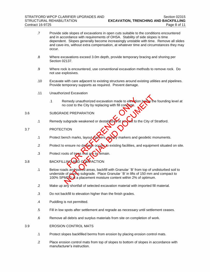
STRATFORD WPCP CLARIFIER UPGRADES AND Section 02315 STRUCTURAL REHABILITATION EXCAVATION, TRENCHING AND BACKFILLING
Contract 16-9725 Page 8 of 11
.7 Provide side slopes of excavations in open cuts suitable to the conditions encountered
and in accordance with requirements of OHSA. Stability of side slopes is time dependent. Slopes generally become increasingly unstable with time. Remove all slides and cave-ins, without extra compensation, at whatever time and circumstances they may occur.
.8 Where excavations exceed 3.0m depth, provide temporary bracing and shoring per Section 02137.
.9 Where rock is encountered, use conventional excavation methods to remove rock. Do not use explosives.
.10 Excavate with care adjacent to existing structures around existing utilities and pipelines. Provide temporary supports as required. Prevent damage.
.11 Unauthorized Excavation
.1 Remedy unauthorized excavation made to elevation below the founding level at no cost to the City by replacing with fill concrete.
3.6 SUBGRADE PREPARATION
.1 Remedy subgrade weakened or destabilized at no cost to the City of Stratford.
3.7 PROTECTION
.1 Protect bench marks, layout markers, survey markers and geodetic monuments.
.2 Protect to ensure no damage occurs to existing facilities, and equipment situated on site.
.3 Protect roots of trees that are to remain.
3.8 BACKFILLING AND COMPACTION
.1 Below roads and paved areas, backfill with Granular `B' from top of undisturbed soil to underside of paving subgrade. Place Granular `B' in lifts of 150 mm and compact to 100% SPMDD at a placement moisture content within 2% of optimum.
.2 Make up any shortfall of selected excavation material with imported fill material.
.3 Do not backfill to elevation higher than the finish grades.
.4 Puddling is not permitted.
.5 Fill in low spots after settlement and regrade as necessary until settlement ceases.
.6 Remove all debris and surplus materials from site on completion of work.
3.9 EROSION CONTROL MATS
.1 Protect slopes backfilled berms from erosion by placing erosion control mats.
.2 Place erosion control mats from top of slopes to bottom of slopes in accordance with manufacturer’s instruction.
FOR REFERENCE O
NLY
NOT OFFIC
IAL B
ID D
OCUMENT

STRATFORD WPCP CLARIFIER UPGRADES AND Section 02315 STRUCTURAL REHABILITATION EXCAVATION, TRENCHING AND BACKFILLING
Contract 16-9725 Page 9 of 11
.3 Secure erosion control mats with galvanized steel stakes, in accordance with
manufacturer printed instruction. Provide galvanized steel stakes at spacing of 1000 mm maximum in each direction.
.4 Backfill the voids between the mats solid with earth.
.5 Maintain slopes of berms by making up materials lost by erosion or any other means. Verify that not more than top one meter of backfill material is lost at any time.
3.10 TRENCHES
.1 Excavate within trench shoring system in accordance with OHSA. Coordinate the work under this Section with Section 02150 - Bracing and Shoring and Section 02140 – Dewatering. Verify that trench is dewatered to ensure that groundwater is lowered and maintained at least 1000 mm below the base of the trench until backfilling is complete.
.2 Excavate trenches to lines, widths and grades as specified in the Contract Documents. Maintain bedding thickness under utilities or duct bank.
.3 Excavate trenches a minimum of 300 mm wider on each side than the outside pipe diameter. Excavate trenches to lines, grades, elevations and dimensions as indicated on the Contract Drawings.
.4 Excavate trench completely and sufficiently in advance of pipe laying to allow proper installation. Do not leave the excavation open for extended periods of time.
.5 Remedy trench excavation weakened or destabilized by improper construction procedure or inadequate dewatering at no cost to the Owner.
.6 Place and compact bedding material in lifts of 150 mm compacted to 95% SPMDD on geotextile on undisturbed ground.
.7 Lay the pipes and backfill trench to a minimum height of 300 mm above the pipe with Granular `A' in lifts of 150 mm compacted to 98% SPMDD.
.8 Where existing utilities are undermined due to work under this section. Backfill the trench from the top of cover to the utility using unshrinkable fill, unless otherwise approved by the Engineer. Provide bond breaker between utility and backfill.
.9 Backfill the rest of the trench with selected excavated material in lifts of 150 mm compacted to 95% SPMDD.
.10 Under roadways and paved areas backfill trenches with Granular `B' in lifts of 150 mm compacted to 100% SPMDD to underside of road subgrade.
3.11 SITE GRADING
.1 Use selected excavated material to rough grade the site. Make up any shortfall in selected excavated material with imported fill material. Place fill in lifts of 300 mm compacted to 95% SPMDD at a placement moisture content within 2% of optimum.
.2 Handle excavated material so that selected topsoil material is placed on top surface.
.3 Raising or lowering of the grade to avoid haulage is not permitted.
.4 Remove stones or rock fragments larger than 100 mm nominal diameter from the top of finished grade.
FOR REFERENCE O
NLY
NOT OFFIC
IAL B
ID D
OCUMENT

STRATFORD WPCP CLARIFIER UPGRADES AND Section 02315 STRUCTURAL REHABILITATION EXCAVATION, TRENCHING AND BACKFILLING
Contract 16-9725 Page 10 of 11
.5 Make adjustments in lines or grades as necessary in order to obtain satisfactory
construction.
.6 Cut and fill to levels required for paved, sodded and landscaped areas. Make allowance for depth of finishes and base courses.
.7 Establish and maintain line and grade stakes for duration of grading operations.
.8 Conform to grades and contours indicated. Uniformly slope grade between elevations shown unless otherwise indicated.
.9 Smoothly slope top and toe of slopes and banks.
.10 Proof roll existing subgrade below paved areas after excavation with a heavy roller. Compact subsoil below paved areas to a minimum 98% SPMDD. Sub-excavate loose, soft and excessively wet areas and areas containing organic material, and fill with suitable fill capable of being compacted to required density.
.11 Establish subgrade parallel to the finished grades indicated and shape in such a manner to permit drainage. Shape subgrade below paved areas to drain to perimeter drains or catchbasins.
.12 Fill, where required, in accordance with requirements for backfilling specified hereinbefore.
.13 Rough grade areas to a tolerance of ±75mm.
3.12 DUST CONTROL
.1 Throughout construction period, provide adequate dust control on the site by watering.
.2 Apply water as often as necessary to provide continuous control of dust from drifting or blowing.
.3 Eliminate dust and dirt in areas where electrical equipment, metering instruments and similar equipment requiring interior cleanliness are being installed or assembled by providing temporary enclosures, covers for openings, or other means of protection.
3.13 HAULAGE
.1 Haul to and dispose of at an approved location on-site, all surplus excavated material not required or suitable for backfill.
.2 Haul surplus excavated material from site in tight bodied trucks or other means. Prevent hauled material from spilling on roads. Promptly clean up if such spill occurs and maintain roads free of any tracked soil. Maintain roads free of any tracked soil.
3.14 FIELD QUALITY CONTROL
.1 Inspection
.1 The City will retain an independent Geotechnical Consultant to inspect foundations for its suitability prior to placement of concrete or other materials.
.2 Notify the City sufficiently in advance of operations, to provide field inspection.
FOR REFERENCE O
NLY
NOT OFFIC
IAL B
ID D
OCUMENT

STRATFORD WPCP CLARIFIER UPGRADES AND Section 02315 STRUCTURAL REHABILITATION EXCAVATION, TRENCHING AND BACKFILLING
Contract 16-9725 Page 11 of 11
.3 On reaching specified excavation level, request an inspection of subgrade by the
Geotechnical Consultant.
.4 Provide all facilities to enable proper inspection.
.5 Do not excavate below the specified level or place concrete or other materials on subgrade until the inspection has been undertaken and permission granted to proceed in writing by the Engineer.
.6 Notify the Engineer if bottom of excavation appears to be unsuitable for foundation. Excavate unsuitable material and backfill as directed by the Engineer.
.2 Soil Compaction Densities
.1 Where specified, compaction densities are percentages of SPMDD in accordance with ASTM D698.
.2 Field tests of soil compaction densities will be carried out in accordance with ASTM D2922 and ASTM D3017.
END OF SECTION
FOR REFERENCE O
NLY
NOT OFFIC
IAL B
ID D
OCUMENT

FOR REFERENCE O
NLY
NOT OFFIC
IAL B
ID D
OCUMENT

STRATFORD WPCP CLARIFIER UPGRADES AND Section 02362 STRUCTURAL REHABILITATION DUST CONTROL
Contract 16-9725 Page 1 of 2
1 GENERAL
1.1 SCOPE
.1 This section describes the Work of dust control.
.2 The Contractor shall be responsible to ensure no dust nuisance arises that may impact neighbouring properties due to his operations during construction.
1.2 RELATED SECTIONS
.1 Division 1 – General Requirements
.2 Section 02200 – Earthwork and Structures
.3 Section 02231 – Clearing and Grubbing
.4 Section 02233 – Preservation of Topsoil
.5 Section 02300 – Earthwork and Related Work
1.3 MEASUREMENT AND PAYMENT
.1 Work outlined in this section is included in the lump sum tender price.
2 PRODUCTS
2.1 MATERIALS
.1 Water shall be free of contaminants that could adversely affect fill material or the environment.
.2 Water shall be free of foreign material that would cause blockage in the spray equipment.
3 EXECUTION
3.1 APPLICATION
.1 Apply water with equipment approved by the Engineer when directed by the Engineer.
.2 Steps shall be taken as necessary to control dust resulting from operations or by public traffic such that it does not:
.1 Affect traffic,
.2 Enter surface waters,
.3 Escape beyond the site or impact the Avon River.
FOR REFERENCE O
NLY
NOT OFFIC
IAL B
ID D
OCUMENT

STRATFORD WPCP CLARIFIER UPGRADES AND Section 02362 STRUCTURAL REHABILITATION DUST CONTROL
Contract 16-9725 Page 2 of 2
.3 Water shall be applied in a manner that avoids ponding, runoff, drifting, and tracking of
the material beyond the area of application.
END OF SECTION
FOR REFERENCE O
NLY
NOT OFFIC
IAL B
ID D
OCUMENT

STRATFORD WPCP CLARIFIER UPGRADES AND Section 02911 STRUCTURAL REHABILITATION TOPSOIL AND FINISH GRADING
Contract 16-9725 Page 1 of 3
1 GENERAL
1.1 SCOPE
.1 This section describes the Work of the supply, placement and grading of topsoil in preparation for planting of trees, shrubs, or other plant materials, or prior to seeding or sodding.
1.2 RELATED SECTION
.1 Division 1 – General Requirements
.2 Section 02311 – Site Grading
1.3 REFERENCES
.1 OPSS 802 – Construction Specification for topsoil
1.4 MEASUREMENT AND PAYMENT
.1 Work outlined in this section is included in the lump sum tender price.
2 PRODUCTS
2.1 TOPSOIL
.1 Topsoil shall be a fertile loam material that is free of roots, vegetation, or other debris of a size and quantity that prevents proper placement of the topsoil. The topsoil shall not contain material greater than 25 mm in size, such as stones and clods.
.2 Topsoil for seeded areas, planting beds: mixture of particulates, microorganisms and organic matter which provides suitable medium for supporting intended plant growth.
.1 All topsoil, supplied by the Contractor shall meet the following requirements:
pH 5.5 – 7.5
Total Salts (mmhos/cm) <1.5
Organic Matter % 4 – 15
Phosphorus (ppm) 10 – 60
Potassium (ppm) 80 – 250
Magnesium (ppm) 100 – 300
Calcium (ppm) 1000 – 4000
Sodium (ppm) <200
Chloride (ppm) <100
Sodium Absorption Ratio <15
Sand Fraction % 20 -75
Silt Fraction % 5 – 50
Clay Fraction % 5 – 30
Texture Loam/Sandy Loam
Atrazine (ppm) <0.05
.2 Contain no toxic elements or growth inhibiting materials.
.3 Finished surface free from:
FOR REFERENCE O
NLY
NOT OFFIC
IAL B
ID D
OCUMENT

STRATFORD WPCP CLARIFIER UPGRADES AND Section 02911 STRUCTURAL REHABILITATION TOPSOIL AND FINISH GRADING
Contract 16-9725 Page 2 of 3
.1 Debris and stones over 50mm diameter.
.2 Course vegetative material, 10mm diameter and 100mm length, occupying more than 2% of soil volume.
.3 Consistence: friable when moist.
2.2 SOIL AMENDMENTS
.1 Fertilizer:
.1 Fertility: major soil nutrients present in the following amounts:
.1 Nitrogen (N): 20 to 40 micrograms of available N per gram of topsoil.
.2 Phosphorus (P): 40 to 50 micrograms of phosphate per gram of topsoil.
.3 Potassium (K): 75 to 110 micrograms of potassium per gram of topsoil.
.4 Calcium, magnesium, sulphur and micro-nutrients present in balanced ratios to support germination and/or establishment of intended vegetation.
.5 pH value: 6.5 to 8.0.
.2 Sand: washed coarse silica sand, medium to course textured.
.3 Fertilizer: industry accepted standard medium containing nitrogen, phosphorous, potassium and any other micro-nutrients suitable to the specific plant species or application or defined by the soil test.
.4 Fertilizer requirements will be determined after obtaining results of soil fertility test.
2.3 SOURCE QUALITY CONTROL
.1 Advise the Engineer of sources of topsoil and manufactured topsoil to be utilized with sufficient lead time for testing.
.2 Contractor is responsible for amendments to supply topsoil as specified.
.3 Provide soil testing results by recognized testing facility for pH, P and K, and organic matter.
3 EXECUTION
3.1 STRIPPING OF TOPSOIL
.1 Commence topsoil stripping of areas as indicated on the Contract Drawings, and as directed by the Engineer, after area has been cleared of brush, weeds and grasses and removed from site.
.2 Strip topsoil to depths as indicated on the Contract Drawings, or as directed by the Engineer. Avoid mixing topsoil with subsoil where textural quality will be moved outside acceptable range of intended application.
.3 Stockpile in locations as directed by the Engineer. Stockpile height not to exceed 3m.
FOR REFERENCE O
NLY
NOT OFFIC
IAL B
ID D
OCUMENT

STRATFORD WPCP CLARIFIER UPGRADES AND Section 02911 STRUCTURAL REHABILITATION TOPSOIL AND FINISH GRADING
Contract 16-9725 Page 3 of 3
.4 Dispose of unused topsoil on-site.
.5 Protect stockpiles from contamination and compaction.
3.2 PREPARATION OF EXISTING GRADE
.1 Verify that grades are correct. If discrepancies occur, notify the Engineer and do not commence work until instructed by the Engineer.
.2 Grade soil, eliminating uneven areas and low spots, ensuring positive drainage.
.3 Remove debris, roots, branches, stones in excess of 50mm diameter and other deleterious materials. Remove soil contaminated with calcium chloride, toxic materials and petroleum products. Remove debris which protrudes more than 75mm above surface. Dispose of removed material off site.
3.3 PLACING AND SPREADING OF TOPSOIL/PLANTING SOIL
.1 Areas where topsoil is to be placed shall be fine graded to a uniform surface. The surface shall be loosened to a depth of 25 mm. It shall be free of all vegetation, debris, and stones which would not be covered by the depth of topsoil.
.2 Place topsoil after the Engineer has accepted subgrade.
.3 Spread topsoil in uniform layers not exceeding 150mm.
.4 Spread topsoil as indicated to following minimum depths after settlement.
.1 150mm for seeded areas.
.5 Manually spread topsoil/planting soil around trees, shrubs and obstacles.
3.4 FINISH GRADING
.1 Grade to eliminate rough spots and low areas and ensure positive drainage. Prepare loose friable bed by means of cultivation and subsequent raking.
.2 Consolidate topsoil to required bulk density using equipment approved by the Engineer. Leave surfaces smooth, uniform and firm against deep foot printing.
3.5 ACCEPTANCE
.1 The Engineer will inspect and test topsoil in place and determine acceptance of material, depth of topsoil and finish grading.
3.6 SURPLUS MATERIAL
.1 Dispose of surplus materials not required on-site.
END OF SECTION
FOR REFERENCE O
NLY
NOT OFFIC
IAL B
ID D
OCUMENT

FOR REFERENCE O
NLY
NOT OFFIC
IAL B
ID D
OCUMENT

STRATFORD WPCP CLARIFIER UPGRADES AND Section 02989 STRUCTURAL REHABILITATION SEEDING
Contract 16-9725 Page 1 of 5
1 SCOPE
.1 This section describes the work of seeding and mulching disturbed areas at the Stratford WPCP.
1.2 REFERENCES
.1 Canada Fertilizers Act (R.S., 1985, c. F-10)
.2 Canada Seeds Act (R.S., 1985, c. S-8)
1.3 PRODUCT HANDLING
.1 All seed and seed mixes shall be in the original factory sealed package with the original legible label securely attached.
.2 All seed and inoculant shall be stored in cool, dry locations until use.
.3 Use all means necessary to protect material before, during and after installation. Provide adequate protection to material which may deteriorate if exposed to elements.
.4 In the event of damage or rejection, make immediate repairs or replace materials at no extra cost to the Owner.
1.4 DELIVERY AND PACKAGING
.1 Fertilizer:
.1 Packaged in waterproof bags, with a label clearly indicating net mass, analysis and manufacturer.
.2 Store on pallets and protect from the elements.
.2 Grass Seed Labelling shall be in accordance with the requirements of the Canada Seeds Act and Regulations. Each package shall be labelled to show:
.1 The name and address of the seed supplier
.2 The name of the seed mix and the various individual seed species that comprise the seed mix and the percentage by mass of each.
.3 The grade of the seed or seed mix.
.4 The supplier's lot designation number corresponding to the Certificate of Seed Analysis.
.5 Mass in kilograms of the seed mix
1.5 SITE CONDITIONS
.1 Immediately after seeding, erect snow fencing to protect seeded areas from traffic until grass is established.
.1 Contractor is responsible for maintaining snow fencing until project is accepted.
.2 Keep site well drained and landscape excavations dry.
FOR REFERENCE O
NLY
NOT OFFIC
IAL B
ID D
OCUMENT

STRATFORD WPCP CLARIFIER UPGRADES AND Section 02989 STRUCTURAL REHABILITATION SEEDING
Contract 16-9725 Page 2 of 5
.3 Clean up immediately any soil or debris spilled onto pavement or concrete.
1.6 MAINTENANCE
.1 Maintain seeded areas for 60 days until acceptance of seeding work. Maintenance includes but is not limited to weeding, fertilizing as required by soil tests, cutting as required to maintain grass at a maximum height of 60 mm and watering. Grass is to be cut at least twice during the maintenance period.
.2 Water seeded areas to sustain its prosperous growth and prevent deterioration. Contractor is responsible for supplying water to the site.
.3 Ensure maintenance equipment is suitable to Owner's Representative.
.4 Keep soil moist during germination period and adequately water grassed areas until accepted by Owner's Representative.
.5 Apply water to ensure moisture penetration of 75 to 100 mm. Control watering to prevent wash-outs.
.6 Cut grass when it reaches height of 60 mm and cut to height of 60 mm. Do not cut more than 33% of blade at any one mowing. Remove clippings. After one year or substantial completion of project, request inspection by Owner's Representative immediately after cutting grass.
.7 Maintain grassed areas free of pests and disease.
.8 Reseed areas which show root growth failure, deterioration, bare or thin spots, or which have been damaged by any means, including replacement operations.
.9 Apply herbicide when it will not cause damage to new grass or other plants.
.1 Avoid use of dicambal and picloram solutions near trees and shrubs.
.2 Use only mecoprop on Bentgrass turf areas.
.10 Contractor is to provide three (3) applications of fertilizer in the first year of maintenance. The timing of fertilizing will depend on when seeding is completed. If seeding is completed in the spring, the second application of fertilizer is to be applied in late June or early July as weather permits. Coverage is not to exceed 3 kg per 100 m2 to be applied evenly and water in well. The third application of fertilizer is to be applied in September or October weather permitting.
.11 If seeding is applied in early August, the second application of fertilizer will occur in September or October weather permitting, and the third application in the following spring as weather permits.
1.7 ACCEPTANCE
.1 Areas will be accepted by Owner's Representative provided that:
.1 Seeded areas are properly established.
.2 Turf is free of eroded, bare or dead spots and 98% free of weeds.
.3 No surface soil is visible when grass has been cut to height of 60 mm.
FOR REFERENCE O
NLY
NOT OFFIC
IAL B
ID D
OCUMENT

STRATFORD WPCP CLARIFIER UPGRADES AND Section 02989 STRUCTURAL REHABILITATION SEEDING
Contract 16-9725 Page 3 of 5
1.8 MEASUREMENT AND PAYMENT
.1 Work outlined in this section is included in the lump sum tender price.
1.9 WARRANTY
.1 Warrant all seeded areas for one (1) year from date of acceptance.
.2 Re-seed all areas which have failed to establish into a healthy, vigorous stand of grass.
2 PRODUCTS
2.1 MATERIALS
.1 Fertilizer: complete commercial fertilizer as recommended by soil test, minimum of 50% of elements derived from organic sources.
.2 Grass seed: Canadian No. 1 seed mixture in accordance with the Canadian Seeds Act, having minimum purity of 97% and germination of 75%.
.3 Mulch for hydro-seeding:
.1 The hydraulic mulch material shall be capable of dispersing rapidly in water to form a homogeneous slurry and remain in such a state when agitated or mixed with other materials. When applied, the hydraulic mulch shall be capable of forming an absorptive mat, which will allow moisture to percolate into the underlying soil. It shall contain no growth of germination inhibiting factors. The mulch shall be dry, free of weeds and all other foreign material and shall be supplied in packages labelled to indicate weight.
.2 The hydraulic mulch shall be a mixture consisting of cellulose pulp and natural sun dried plant fibres processed in lengths 15 mm minimum and 25 mm maximum.
.4 Water: potable, free of impurities that would inhibit germination.
2.2 SEED MIXTURES:
.1 Seed mix shall conform to the following:
.1 Minimum Seed Germination: 70%
.2 Minimum Seed Purity: 85%
.3 Maximum Weed Sees: 0.5%
.4 Creeping Red Fescue: festuca rubra: 50%
.5 Kentucky Bluegrass: Poa pratensis: 10%
.6 Perennial Ryegrass: Lolium perrenne: 35%
.7 White Clover: Trifolum repens: 5%
FOR REFERENCE O
NLY
NOT OFFIC
IAL B
ID D
OCUMENT

STRATFORD WPCP CLARIFIER UPGRADES AND Section 02989 STRUCTURAL REHABILITATION SEEDING
Contract 16-9725 Page 4 of 5
3 EXECUTION
3.1 WORKMANSHIP
.1 Keep site well drained.
.2 Seeding may be completed by hydro-seeding.
.3 Clean up immediately, soil, mulch or other debris spilled onto pavement, dispose of deleterious materials.
.4 Take reasonable care to prevent contamination by seeding slurry of structures, signs, guiderails, fences and utilities.
.5 Where contamination occurs, remove seeding slurry to satisfaction of the Owner's Representative.
3.2 PREPARATION OF SURFACES
.1 All areas to be seeded shall be fine graded to a uniform surface and the surface materials shall be loosened to a depth of 25 mm whether or not topsoil has been applied. These areas shall be so maintained until they are seeded and mulched. Stones and all other surface litter shall be removed and disposed of outside the right-of-way at locations arranged for by the contractor.
.2 Obtain Owner's Representative's approval of seed bed preparation including topsoil grades, and depth before starting seeding. No seeding will be accepted unless seed bed preparation has been inspected and approved prior to completion of work.
3.3 SEEDING
.1 Seed area during early spring or after 15th of August to September 15th.
.2 Apply when winds less than 10 km/h using equipment suitable for area involved to the approval of the Owner's Representative.
.3 Measure quantities of material by mass or mass-calibrated volume measurement to satisfaction of Owner's Representative.
.4 Seed, fertilizer and hydraulic mulch shall be thoroughly mixed in a water slurry and be distributed uniformly over the surface area via an approved hydraulic mulcher.
.5 The Contractor shall measure the quantities of each of the materials to be charged into the hydraulic mulcher, either by weight or by a system of mass calibrated volume measurements. After charging, no water or other material shall be added to the mixture in the hydraulic mulcher.
.6 Complete slurry to be applied as follows:
.1 Seed: as per manufacturer’s specifications
.2 Mulch 2,000 kg/per hectare
.3 Water, minimum 10,000 L per hectare
.7 Blend applications into adjacent grass areas.
FOR REFERENCE O
NLY
NOT OFFIC
IAL B
ID D
OCUMENT

STRATFORD WPCP CLARIFIER UPGRADES AND Section 02989 STRUCTURAL REHABILITATION SEEDING
Contract 16-9725 Page 5 of 5
END OF SECTION
FOR REFERENCE O
NLY
NOT OFFIC
IAL B
ID D
OCUMENT

FOR REFERENCE O
NLY
NOT OFFIC
IAL B
ID D
OCUMENT

STRATFORD WPCP CLARIFIER UPGRADES AND Division 3 STRUCTURAL REHABILITATION CONCRETE Contract 16-9725
DIVISION 3 – CONCRETE
FOR REFERENCE O
NLY
NOT OFFIC
IAL B
ID D
OCUMENT

FOR REFERENCE O
NLY
NOT OFFIC
IAL B
ID D
OCUMENT
STRATFORD WPCP CLARIFIER UPGRADES AND Division 3 STRUCTURAL REHABILITATION CONCRETE Contract 16-9725 Table of Contents
DIVISION 3 – CONCRETE
Section No. Title
03100 Concrete Forms and Accessories
03200 Concrete Reinforcement
03252 Waterstops
03300 Cast-in-Place Concrete
03600 Grout
03800 Polyurethane Injection
03905 Concrete Repairs
FOR REFERENCE O
NLY
NOT OFFIC
IAL B
ID D
OCUMENT

FOR REFERENCE O
NLY
NOT OFFIC
IAL B
ID D
OCUMENT

STRATFORD WPCP CLARIFIER UPGRADES AND Section 03100 STRUCTURAL REHABILIATION CONCRETE FORMS AND ACCESSORIES
Contract 16-9725. Page 1 of 3
1 GENERAL
1.1 RELATED SECTIONS
.1 Section 03200 – Concrete Reinforcement
.2 Section 03252 – Waterstops
.3 Section 03300 – Cast-in-Place Concrete
1.2 MEASUREMENT AND PAYMENT
.1 No measurement will be made under this section. Include costs in items of work for which concrete formwork and falsework is required.
1.3 REFERENCES
.1 Canadian Standards Association (CSA):
.1 CSA A23.1-09/A23.2-09 (R2014) - Concrete Materials and Methods of Concrete Construction / Test Methods and Standard Practices for Concrete
.2 CSA O86-14 - Engineering Design in Wood
.3 CSA O121-08 (R2013) - Douglas Fir Plywood
.4 CSA S269.1-1975 (R2003) - Falsework for Construction Purposes
.5 CAN/CSA S269.3-M92 (R2013) - Concrete Formwork
.2 International Organization for Standardization
.1 ISO 16893 (2011) – Wood-Based Panels – Particleboard
.3 Council of Forest Industries of British Columbia (COFI):
.1 COFI Exterior Plywood for Concrete Formwork
2 PRODUCTS
2.1 MATERIALS
.1 Formwork materials:
.1 For concrete without special architectural features, use wood and wood product formwork materials to CSA O121, CSA O86 and ISO 168693 Type P-HLB HMR.
.2 Form ties:
.1 For concrete not designated ‘Architectural’, use removable or snap-off metal ties, fixed or adjustable length, free of devices leaving holes larger than 25 mm diameter in concrete surface.
.2 Provide waterstops on all ties through water retaining structures.
.3 Form panels:
FOR REFERENCE O
NLY
NOT OFFIC
IAL B
ID D
OCUMENT

STRATFORD WPCP CLARIFIER UPGRADES AND Section 03100 STRUCTURAL REHABILIATION CONCRETE FORMS AND ACCESSORIES
Contract 16-9725. Page 2 of 3
.1 Plywood: high density overlay Douglas Fir to CSA O121 No.1 grade, square
edge, 20mm thick.
.4 Form liner:
.1 Zemdrain® MD, Type III “Controlled Permeability Formliner” (CPF) as produced by Dupont, Maximum uses before discard: 3.
.2 Formtex® controlled permeability formliner (CPF) as produced by Fibertex® or Zemdrain® Classic, Type II CPF by Dupont. Maximum uses before discard: 1. This requirement will be strictly enforced.
.5 Form release agent: non-toxic, biodegradable, low VOC.
.6 Preformed joint filler: Cemar flexible foam expansion joint filler by Greenstreak c/w joint cap.
3 EXECUTION
3.1 FABRICATION AND ERECTION
.1 Verify lines, levels and centres before proceeding with formwork/falsework and ensure dimensions agree with drawings.
.2 Apply Formliner (CPF) to surface of forms with anchors spaced at not more than 400 mm c/c each way, and in strict accordance with the manufacturer’s written instructions.
.3 Apply Formliner (CPF) to both sides of all walls.
.4 Fabricate and erect formwork in accordance with CAN/CSA S269.3 to produce finished concrete conforming to shape, dimensions, locations, and levels indicated within tolerances required by CAN/CSA A23.1/A23.2.
.5 Align form joints and make watertight. Keep form joints to minimum.
.6 Do not use form release agents on forms with CPF.
.7 Use 25 mm chamfer strips on external corners and/or 25 mm fillets at interior corners and joints, unless specified otherwise.
.8 Form chases, slots, openings, drips, recesses, expansion, and control joints as indicated.
.9 Build in anchors, sleeves, and other inserts required to accommodate work specified in other sections. Assure that all anchors and inserts will not protrude beyond surfaces designated to receive applied finishes, including painting.
.10 Clean formwork in accordance with CAN/CSA A23.1/A23.2, before placing concrete.
3.2 SUBMITTALS
.1 Submit formwork and falsework drawings.
.2 Submit both typical arrangements and specific configurations for each pour.
.3 Show layout and dimensions of construction joints in the structure.
.4 Show materials and layout of panels for formwork.
FOR REFERENCE O
NLY
NOT OFFIC
IAL B
ID D
OCUMENT

STRATFORD WPCP CLARIFIER UPGRADES AND Section 03100 STRUCTURAL REHABILIATION CONCRETE FORMS AND ACCESSORIES
Contract 16-9725. Page 3 of 3
.5 Show extent and layout of reglets, etc.
.6 Comply with CSA-S269.1 for falsework drawings.
.7 Comply with CSA-S269.3 for concrete formwork drawings.
3.3 REMOVAL AND RESHORING
.1 Leave formwork in place for the following minimum periods of time after placing concrete.
.1 Seven (7) days for walls and sides of beams.
.2 Two (2) days for columns.
.3 Two (2) days for footings and abutment.
.4 Contractor Note: The ambient conditions may require additional curing at the discretion of the Engineer.
.2 After removing formwork, provide shoring under beams and suspended slabs for a minimum of 21 days.
.3 Re-use formwork and falsework subject to requirements of CAN/CSA A23.1/A23.2.
.4 The Zemdrain® MD Type III CPF may be used a maximum of three times before it must be replaced with a new liner. If CPF becomes torn or clogged, remove and replace immediately.
.5 The Formtex® CPF or the Zemdrain® Classic CPF may only be used one time, without exception.
.6 Totally remove any sections of liner which may have become embedded in the concrete and restore the surface at these locations to the approval of the Engineer
.7 Where the CPF has created folds, ridges or creases in the finished sides of concrete walls in occupied areas for any reason, finish the concrete wall surface in its entirety with a sac rubbed parge coat to the satisfaction of the Engineer.
END OF SECTION
FOR REFERENCE O
NLY
NOT OFFIC
IAL B
ID D
OCUMENT

FOR REFERENCE O
NLY
NOT OFFIC
IAL B
ID D
OCUMENT

STRATFORD WPCP CLARIFIER UPGRADES AND Section 03200 STRUCTURAL REHABILIATION CONCRETE REINFORCEMENT
Contract 16-9725 Page 1 of 3
1 GENERAL
1.1 RELATED SECTIONS
.1 Section 03100 – Concrete Forms and Accessories
.2 Section 03300 – Cast-in-Place Concrete
1.2 MEASUREMENT AND PAYMENT
.1 No measurement will be made under this section. Include costs in items of concrete work for which reinforcement is required.
1.3 REFERENCES
.1 Canadian Standards Association (CSA):
.1 CSA A23.1-14/A23.2-14 - Concrete Materials and Methods of Concrete Construction / Test Methods and Standard Practices for Concrete
.2 CSA A23.3-14 - Design of Concrete Structures
.3 CAN/CSA G30.18-09 (R2014) - Carbon Steel Bars for Concrete Reinforcement
.4 CSA G40.20-13/G40.21-13 - General Requirements for Rolled or Welded Structural Quality Steel/Structural Quality Steel
.5 CSA W186-M1990 (R2012) - Welding of Reinforcing Bars in Reinforced Concrete Construction
.2 American Concrete Institute (ACI):
.1 ACI SP-66 (04) - ACI Detailing Manual-2004
.3 Reinforcing Steel Institute of Canada (CRSI):
.1 CRSI Manual of Standard Practise 2009
.4 American Society for Testing and Materials (ASTM):
.1 ASTM A1064/A1064M-15 - Standard Specification for Carbon-Steel Wire and Welded Wire Reinforcement, Plain and Deformed, for Concrete
.2 ASTM A775/A775M-07b (2014) - Standard Specification for Epoxy-Coated Steel Reinforcing Bars
1.4 SHOP DRAWINGS
.1 Submit shop drawings in accordance with Section 01330 – Submittals.
.2 Indicate on shop drawings bar bending details, lists, quantities of reinforcement, sizes, spacings, locations of reinforcement and mechanical splices if approved by engineer, with identifying code marks to permit correct placement without reference to structural drawings. Indicate sizes, spacings and locations of chairs, spacers and hangers. Prepare reinforcement drawings in accordance with Reinforcing Steel Manual of Standard Practice – by Reinforcing Steel Institute of Canada.
FOR REFERENCE O
NLY
NOT OFFIC
IAL B
ID D
OCUMENT

STRATFORD WPCP CLARIFIER UPGRADES AND Section 03200 STRUCTURAL REHABILIATION CONCRETE REINFORCEMENT
Contract 16-9725 Page 2 of 3
.3 Detail lap lengths and bar development lengths to CAN/CSA A23.3. Provide Type B
tension lap splices, unless otherwise indicated.
2 PRODUCTS
2.1 MATERIALS
.1 Substitute different size bars only if permitted in writing by Engineer.
.2 Reinforcing steel: billet steel, grade 400 MPa, deformed bars to CAN/CSA G30.18, unless indicated otherwise.
.3 Welded steel wire fabric: to ASTM A1064/A1064M. Provide in flat sheets only.
.4 Chairs, bolsters, bar supports, spacers: to CSA A23.1/A23.2.
.5 Mechanical splices: subject to approval of Engineer.
.6 Plain round bars: to CAN/CSA G40.21.
.7 Specification for epoxy-coated reinforcing bars: ASTM A775/A775M.
2.2 FABRICATION
.1 Fabricate reinforcing steel in accordance with CAN/CSA A23.1, ACI SP-66 and Reinforcing Steel Manual of Standard Practice by the Reinforcing Steel Institute of Canada, unless indicated otherwise.
.2 Obtain Engineer’s approval for locations of reinforcement splices other than those shown on placing drawings.
.3 Upon approval of Engineer, weld reinforcement in accordance with CSA W186.
.4 Ship bundles of bar reinforcement, clearly identified in accordance with bar bending details and lists.
2.3 SOURCE QUALITY CONTROL
.1 Upon request, provide Engineer with certified copy of mill test report of reinforcing steel, showing physical and chemical analysis, minimum four weeks prior to commencing reinforcing work.
.2 Upon request, inform Engineer of proposed source of material to be supplied.
3 EXECUTION
3.1 FIELD BENDING
.1 Do not field bend or field weld reinforcement, except where authorized in writing by Engineer.
.2 When field bending is authorized, bend without heat, applying a slow and steady pressure.
.3 Replace bars that develop cracks or splits.
3.2 PLACING REINFORCEMENT
FOR REFERENCE O
NLY
NOT OFFIC
IAL B
ID D
OCUMENT

STRATFORD WPCP CLARIFIER UPGRADES AND Section 03200 STRUCTURAL REHABILIATION CONCRETE REINFORCEMENT
Contract 16-9725 Page 3 of 3
.1 Place reinforcing steel as indicated on the structural drawings, on reviewed placing
drawings and in accordance with CSA A23.1.
.2 Use plain round bars as slip dowels in concrete. Paint portion of dowel intended to move within hardened concrete with one coat of asphalt paint. When paint is dry, apply a thick even film of mineral lubricating grease.
.3 Prior to placing concrete, provide 72 hours’ notice to Engineer and facilitate access for Engineer to review reinforcement placement. Make all necessary corrections before concrete is placed and allow re-inspection by Engineer, if requested.
.4 Ensure cover to reinforcement is maintained during concrete pour.
.5 Touch-up damaged and cut ends of epoxy coated rebar with compatible finish to provide continuous coating.
END OF SECTION
FOR REFERENCE O
NLY
NOT OFFIC
IAL B
ID D
OCUMENT

FOR REFERENCE O
NLY
NOT OFFIC
IAL B
ID D
OCUMENT

STRATFORD WPCP CLARIFIER UPGRADES AND Section 03252 STRUCTURAL REHABILIATION WATERSTOPS
Contract 16-9725 Page 1 of 5
1 GENERAL
1.1 SECTION INCLUDES
.1 Provision of waterstops embedded in concrete and spanning control, expansion and/or construction joints to create a continuous diaphragm to prevent fluid migration.
1.2 REFERENCES
.1 Corps of Engineers - CRD-C 572-74
.2 American Society for Testing and Materials (ASTM):
.1 ASTM D570-98 (2010) e1 - Standard Test Method for Water Absorption of Plastics
.2 ASTM D624-00 (2012) - Standard Test Method for Tear Strength of Conventional Vulcanized Rubber and Thermoplastic Elastomers
.3 ASTM D638-14 - Standard Test Method for Tensile Properties of Plastics
.4 ASTM D746-14 - Standard Test Method for Brittleness Temperature of Plastics and Elastomers by Impact
.5 ASTM D747-10 - Standard Test Method for Apparent Bending Modulus of Plastics by Means of a Cantilever Beam
.6 ASTM D792-13 - Standard Test Methods for Density and Specific Gravity (Relative Density) of Plastics by Displacement
.7 ASTM D2240-05 (2010) - Standard Test Method or Rubber Property - Durometer Hardness
.8 ASTM D412-06a (2013) - Standard Test Methods for Vulcanized Rubber and Thermoplastic Elastomers - Tension
.3 Bureau of Reclamation - C-902
1.3 QUALITY ASSURANCE
.1 Waterstop manufacturer shall demonstrate five (5) years (minimum) continuous, successful experience in production of waterstops.
1.4 DELIVERY, STORAGE AND HANDLING
.1 Store waterstops under tarps to protect from oil, dirt, sunlight and premature exposure to water.
2 PRODUCTS
2.1 PVC WATERSTOPS FOR EXPANSION JOINTS AND CONSTRUCTION JOINTS
.1 Provide flexible PVC (polyvinyl chloride) waterstop as manufactured by Greenstreak, profile style number 696, or approved equal, for all expansion joints.
FOR REFERENCE O
NLY
NOT OFFIC
IAL B
ID D
OCUMENT

STRATFORD WPCP CLARIFIER UPGRADES AND Section 03252 STRUCTURAL REHABILIATION WATERSTOPS
Contract 16-9725 Page 2 of 5
.2 Provide flexible PVC (polyvinyl chloride) waterstop as manufactured by Greenstreak,
profile style number 647, or approved equal, for all construction joints indicated on structural drawings.
.3 The PVC waterstop shall be extruded from an elastomeric plastic material of which the basic resin is prime virgin polyvinyl chloride. The PVC compound shall not contain any scrapped or reclaimed material or pigment whatsoever.
.4 Performance Requirements as follows:
Property Test Method Required Limits
Water Absorption ASTM D570 0.15% maximum
Tear Resistance ASTM D624 35 kN/m minimum
Ultimate Elongation ASTM D638 350% minimum
Tensile Strength ASTM D638 13.78 MPa minimum
Low Temperature Brittleness ASTM D746 No Failure @ -37ºC
Stiffness in Flexure ASTM D747 4.13 MPa minimum
Specific Gravity ASTM D792 1.45 maximum
Hardness, Shore A ASTM D2240 79 ± 3
Tensile Strength after accelerated
extraction
CRD-C 572 11.03 MPa minimum
Elongation after accelerated extraction CRD-C 572 300% minimum
Effect of Alkalies after seven (7) days:
Weight Change
Hardness Change
CRD-C 572 between -0.10% /
+0.25%
±5 points
2.2 HYDROPHILIC WATERSTOP
.1 Use hydrophilic waterstop only where specifically shown on design drawings. If no waterstop is shown, use PVC type waterstop by default.
.2 Provide hydrophilic rubber waterstop as supplied by Multiurethanes, “Hydrotite” profile style number CJ-0725, or approved equal.
.3 The waterstop shall be a combination of chloroprene rubber and chloroprene rubber modified to impart hydrophilic properties.
.4 The waterstop shall have a delay coating to inhibit initial expansion due to moisture present in fresh concrete.
.5 Performance Requirements as follows:
Chloroprene Rubber
Property Test Method Required Limits
Tensile Strength ASTM D412 9 MPa (1300 PSI) minimum
Ultimate Elongation ASTM D412 400% minimum
FOR REFERENCE O
NLY
NOT OFFIC
IAL B
ID D
OCUMENT
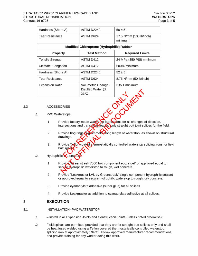
STRATFORD WPCP CLARIFIER UPGRADES AND Section 03252 STRUCTURAL REHABILIATION WATERSTOPS
Contract 16-9725 Page 3 of 5
Hardness (Shore A) ASTM D2240 50 ± 5
Tear Resistance ASTM D624 17.5 N/mm (100 lb/inch)
minimum
Modified Chloroprene (Hydrophilic) Rubber
Property Test Method Required Limits
Tensile Strength ASTM D412 24 MPa (350 PSI) minimum
Ultimate Elongation ASTM D412 600% minimum
Hardness (Shore A) ASTM D2240 52 ± 5
Tear Resistance ASTM D624 8.75 N/mm (50 lb/inch)
Expansion Ratio Volumetric Change -
Distilled Water @
21ºC
3 to 1 minimum
2.3 ACCESSORIES
.1 PVC Waterstops:
.1 Provide factory-made waterstop fabrications for all changes of direction, intersections and transitions leaving only straight butt joint splices for the field.
.2 Provide hog rings or grommets along length of waterstop, as shown on structural drawings.
.3 Provide Teflon coated thermostatically controlled waterstop splicing irons for field butt splices.
.2 Hydrophilic Waterstops:
.1 Provide “Greenstreak 7300 two component epoxy gel” or approved equal to secure hydrophilic waterstop to rough, wet concrete.
.2 Provide “Leakmaster LVI, by Greenstreak” single component hydrophilic sealant or approved equal to secure hydrophilic waterstop to rough, dry concrete.
.3 Provide cyanacrylate adhesive (super glue) for all splices.
.4 Provide Leakmaster as addition to cyanacrylate adhesive at all splices.
3 EXECUTION
3.1 INSTALLATION- PVC WATERSTOP
.1 – Install in all Expansion Joints and Construction Joints (unless noted otherwise):
.2 Field splices are permitted provided that they are for straight butt splices only and shall be heat fused welded using a Teflon covered thermostatically controlled waterstop splicing iron at approximately 194ºC. Follow approved manufacturer recommendations, and provide training for any worker doing this work.
FOR REFERENCE O
NLY
NOT OFFIC
IAL B
ID D
OCUMENT

STRATFORD WPCP CLARIFIER UPGRADES AND Section 03252 STRUCTURAL REHABILIATION WATERSTOPS
Contract 16-9725 Page 4 of 5
.3 Lapping of waterstop, use of adhesives or solvents shall not be allowed.
.4 Centre waterstop in joint and secure waterstop in correct position using hog rings or grommets along the length of the waterstop and wire tie to adjacent reinforcing steel. See structural drawings for details.
3.2 INSTALLATION - HYDROPHILIC WATERSTOP –
.1 Install Hydrophilic Waterstop only where specified:
.2 Cut coil ends square (or at proper angle for mitred corners) with shears or sharp blade to fit splices together without overlaps.
.3 Splices shall be sealed using cyanacrylate adhesive (super glue) and “Leakmaster LVI, by Greenstreak” or approved equal.
.4 Seal watertight any exposed cells of hydrophilic waterstop using “Leakmaster LVI, by Greenstreak” or approved equal.
.5 Follow approved manufacturer recommendations.
.6 Hydrophilic waterstop must be installed on clean, dry, smooth, structurally sound concrete.
.7 Clean concrete substrate of all dust, debris and laitance.
.8 Remove the protective release tape and press the profile firmly onto the concrete substrate in the proper location. Do not reposition after initial contact with the concrete.
.9 Hydrophilic waterstop allied to vertical or overhead surfaces to be further secured with concrete nails spaced approximately 600 mm on centers.
.10 Join lengths of the hydrophilic waterstop profile with cyanacrylate (super glue) type adhesive. Joints to be dressed with a bead of “Leakmaster” Hydrophilic Caulk or approved equal. Intersections and changes of direction must be joined in a similar manner.
.11 Installation temperatures above 4.5ºC are preferred. Low temperature installations (below 4.5ºC) require superficial heating of the concrete substrate immediately prior to the application of the hydrophilic waterstop profile. Carefully warm and dry the concrete surface with a hot air gun or propane torch and apply the hydrophilic waterstop profile while surface is still warm. Store the hydrophilic waterstop profile in a heated location until ready to install.
.12 Adhesive performance may be affected by adverse storage conditions and time. Store in a cool, dry location and use within two (2) months of purchase.
3.3 HYDROPHILIC AND PVC INTERSECTIONS:
.1 Maintain continuity of waterstops at all intersections and transitions.
.2 Joinery between PVC and hydrophilic waterstop shall be sealed using “Leakmaster LVI” by Greenstreak or approved equal.
.3 Follow approved manufacturer recommendations.
3.4 FIELD QUALITY CONTROL
FOR REFERENCE O
NLY
NOT OFFIC
IAL B
ID D
OCUMENT

STRATFORD WPCP CLARIFIER UPGRADES AND Section 03252 STRUCTURAL REHABILIATION WATERSTOPS
Contract 16-9725 Page 5 of 5
.1 Waterstop splicing defects that are unacceptable include, but are not limited to, the
following:
.1 Tensile strength less than 80 percent of parent section.
.2 Misalignment of centerbulb, ribs and bulbs greater than 1.5 mm.
.3 Bond failure at joint deeper than 1.5 mm or fifteen (15) percent of material thickness.
.4 Misalignment which reduces waterstop cross section more than fifteen (15) percent.
.5 Visible porosity in the weld.
.6 Bubbles or inadequate bonding.
.7 Visible signs of splice separation when cooled splice is bent by hand at a sharp angle.
.8 Charred or burnt material.
END OF SECTION
FOR REFERENCE O
NLY
NOT OFFIC
IAL B
ID D
OCUMENT

FOR REFERENCE O
NLY
NOT OFFIC
IAL B
ID D
OCUMENT

STRATFORD WPCP CLARIFIER UPGRADES AND Section 03300 STRUCTURAL REHABILIATION CAST-IN-PLACE CONCRETE Contract 16-9725 Page 1 of 15
1 GENERAL
1.1 SCOPE OF WORK
.1 Work supplied under this section includes the supply, testing and installation of cast-in-place concrete.
1.2 RELATED SECTIONS
.1 Section 03100 – Concrete Forms and Accessories
.2 Section 03200 – Concrete Reinforcement
.3 Section 03252 – Waterstops
.4 Section 03600 – Grout
.5 Section 05500 – Metal Fabrications
.6 Section 07120 – Bituminous Dampproofing
1.3 REFERENCES (LATEST EDITION AT THE TIME OF TENDER)
.1 Ontario Building Code (OBC) 2012
.2 National Building Code of Canada (NBC) 2010
.3 Canadian Standards Association (CSA):
.1 CSA A23.1-14/A23.2-14 – Concrete Materials and Methods of Concrete Construction/Test Methods and Standard Practices for Concrete
.2 CSA A23.3-14 – Design of Concrete Structures
.3 CAN/CSA A3000-13 - Cementitious Materials Compendium
.4 American Concrete Institute (ACI):
.1 ACI 350-06 - Code Requirements for Environmental Engineering Concrete Structures and Commentary
.2 ACI 350.1M - Metric Specification for Tightness Testing of Environmental Engineering Concrete Containment Structures
.3 ACI 214R-11 - Guide to Evaluation of Strength Test Results of Concrete
.5 American Society for Testing and Materials (ASTM):
.1 ASTM C260/C260M-10a – Specification for Air-Entraining Admixtures for Concrete
.2 ASTM C309-11 - Specification for Liquid Membrane-Forming Compounds for Curing Concrete
.3 ASTM C494/C494M-13 - Specification for Chemical Admixtures for Concrete
FOR REFERENCE O
NLY
NOT OFFIC
IAL B
ID D
OCUMENT

STRATFORD WPCP CLARIFIER UPGRADES AND Section 03300 STRUCTURAL REHABILIATION CAST-IN-PLACE CONCRETE Contract 16-9725 Page 2 of 15
.4 ASTM C1017/C1017M-13e1 - Standard Specification for Chemical Admixtures
for Use in Producing Flowing Concrete
1.4 MEASUREMENT AND PAYMENT
.1 The total volume of the Cast-in-Place concrete will not be measured and the work will be paid for at the price included in the bid form for this section based on the percentage of the work completed.
.2 Heating of water and aggregates and providing cold weather protection will not be measured but considered incidental to work.
.3 Cooling of concrete and providing hot weather protection will not be measured but considered incidental to work.
.4 Coordination with other trades for the supply of hardware, pipe sleeves, and other embedded materials including the related layout drawing and installation will not be measured but considered incidental to work.
.5 Supply and installation of waterstops, construction joints, and expansion joints will not be measured but considered incidental to work.
.6 Repair of any deficiencies in the concrete will not be measured but be considered incidental to work.
1.5 QUALITY ASSURANCE
.1 Performance of Concrete Mixes
.1 Concrete will be tested as identified in the mix performance part of this specification which includes Section 1.6 “Prequalification Test Results”, Section 1.7 “Trial Mixes” and Section 1.9 “Testing of Ready Mix Concrete”.
.2 Cracking of concrete in the structure is generally considered to be detrimental to the long term performance. All cracks resulting in any visible leakage must be repaired. Even though “low shrinkage concrete” is specified, cracking will occur and must be repaired by the Contractor at no cost to the Owner.
1.6 SUBMITTALS
.1 Certification of Materials and Concrete Producer
.1 Submit to the Consulting Engineer for review of the following information:
.1 Statements identifying the sources and certifying:
.1 Cement types, sources, and conformance to CSA A23.1/A23.2 and CAN/CSA-A3000
.2 Aggregates comply with CSA A23.1/A23.2 and are from M.T.O. designated sources list; submit gradations
.3 Admixture product names and certification that they comply with CSA A23.1/A23.2 and ASTM C260, ASTM C494/C494M, or ASTM C1017/ C1017M. State type or class of admixture.
FOR REFERENCE O
NLY
NOT OFFIC
IAL B
ID D
OCUMENT

STRATFORD WPCP CLARIFIER UPGRADES AND Section 03300 STRUCTURAL REHABILIATION CAST-IN-PLACE CONCRETE Contract 16-9725 Page 3 of 15
.4 Materials, plant, and equipment to be used in concrete work
comply with the requirements of CSA A23.1/A23.2.
.2 Proposed mix designs including complete details of product additives and certification that all additives are compatible with all other additives.
.2 Prequalification Test Results
.1 Submit prequalification test results to the Engineer for each Ready Mix Concrete Mix proposed, showing adequate performance for:
.1 Compressive strength
.2 The standard deviation for the concrete compressive strength tests in conformance with ACI 214R.
.3 Linear shrinkage
.4 Air entrainment
.3 Trial Mixes
.1 Prior to the start of on-site concrete construction, prepare trial mixes of each structural concrete mix design to confirm the mix-design satisfies the performance and workability requirements. The test for the workability of the mix must involve a full truckload of the proposed concrete mix, transported from the truck, placed and consolidated in an area of the Contractor’s choosing, using the proposed conveyance system. Trial mixes and related workability proof testing must have occurred within three (3) months of the first concrete pour or they will not be considered valid.
.2 Submit test results from each trial mix confirming concrete strength, air-content and linear shrinkage. Submit a minimum of three linear shrinkage test results for each mix. Linear shrinkage tests must be current to within three (3) months of project commencement. The tested concrete must contain all materials that will be supplied to the site and be from the batch plant that will supply the site.
.3 Adjust mixes that do not provide adequate performance, retest and resubmit the test results as noted above.
.4 After review and acceptance of the mix designs, supply concrete in accordance with the reviewed mixes.
.4 Concrete Work Plan
.1 Prior to the start of on-site concrete construction, prepare a concrete work plan in accordance with the requirements in section 3.2.1.4 and 3.2.2.2, including concrete mix production, concrete placing procedures and casting sequence, and curing procedures.
.2 Submit the work plan to the Consulting Engineer for approval at least 10 days prior to the pre-construction concrete meeting as outlined in 3.2.1.
.5 Testing of Ready Mix Concrete
.1 Testing will be performed by an independent testing agency arranged by the Owner.
FOR REFERENCE O
NLY
NOT OFFIC
IAL B
ID D
OCUMENT

STRATFORD WPCP CLARIFIER UPGRADES AND Section 03300 STRUCTURAL REHABILIATION CAST-IN-PLACE CONCRETE Contract 16-9725 Page 4 of 15
.2 Testing of Ready Mix Concrete trucks on delivery will include:
.1 Slump
.2 Air content
.3 Wet density
.4 Concrete temperature
.3 Samples will be cast for laboratory testing for:
.1 Compressive strength
.2 Linear shrinkage
.4 Initially 3, 7, 14, and 2-28 day compression samples will be taken and tested. However, upon achieving acceptable results the testing will be reduced to 7 and 2-28 day tests.
.5 Samples may be taken for other testing as determined by the Engineer.
.6 Copies of all concrete testing carried out by the Engineer will be made available to the Contractor upon request.
.7 The use of testing services does not relieve the Contractor of the responsibility to furnish materials and construction in compliance with the performance requirements of the contract documents.
.8 The Contractor shall take samples and carry out testing as part of their quality control procedures to verify that the concrete satisfies the performance requirements set out in these specifications. Where possible, these tests shall be carried out on the same batches as tested by the independent testing agency.
.9 Copies of the test results for all tests carried out by the Contractor must be made available to the Engineer for review and records.
2 PRODUCTS
2.1 MATERIALS FOR CONCRETE MIXES
.1 Use materials conforming to CSA A23.1/A23.2, and to the performance requirements which have been established in this section.
.2 Cement
.1 Normal Portland Cement (Type GU) blended with cementitious slag. Use Portland cement and Slag cement conforming to CSA A3000 and comply to the following conditions and requirements:
.1 For concrete mixes, the supplier may incorporate cementitious slag into the proposed mix design as a replacement for up to 30 percent by mass of the quantity of Type GU Portland cement.
.2 For lean concrete, slag cannot be used to replace any of the Portland cement.
FOR REFERENCE O
NLY
NOT OFFIC
IAL B
ID D
OCUMENT

STRATFORD WPCP CLARIFIER UPGRADES AND Section 03300 STRUCTURAL REHABILIATION CAST-IN-PLACE CONCRETE Contract 16-9725 Page 5 of 15
.3 Additives
.1 Conform to CSA A23.1/A23.2 and ASTM C260, ASTM C494/C494M, or ASTM C1017/C1017M. State type or class of admixture.
.2 Use admixtures from one manufacturer and satisfy the intent and, where practical, the specific recommendations of that manufacturer.
.3 Ensure admixtures are compatible with each other and with any construction materials used that will be in contact with concrete. Ensure that the mix remains workable with the inclusion of such admixtures.
.4 Do not use calcium chloride nor admixtures containing chlorides.
.5 Shrinkage Reducing Admixture (not covered by CSA or ASTM standards).
.1 A shrinkage reducing admixture shall be used in all topping mixes and in elements with thickness of 125 mm or less.
.2 A shrinkage compensating admixture may be used where appropriate or as necessary to meet linear shrinkage testing requirements specified herein.
.3 Acceptable products Tetraguard AS20 by Master Builders added at a rate of 2.5 percent by weight of cementitious materials, or Eclipse by Grace Construction Products added at a rate of 2 percent by weight of cementitious materials.
.4 Aggregate
.1 Starter mixes to have no large aggregate.
.2 All mixes for concrete elements with thicknesses of 125 mm or less shall contain 10 mm aggregate.
.3 Use 20 mm aggregate in the remainder of the mixes, unless approved or otherwise specified by the Engineer.
2.2 CONCRETE MIXES
.1 Supply concrete to meet the project performance requirements. Structural Concrete specified herein is required to be “High Performance Concrete” for increased durability and watertightness, and reduced shrinkage and cracking, compared to regular structural concrete.
.2 The high performance mix shall be manufactured under the requirements of Clause 8.8 “Low Shrinkage Concrete” of CSA A23.1/A23.2.
.3 Proportion in accordance with CSA A23.1/A23.2 - Table 5 Alternative Methods for Specifying Concrete.
.4 Meet or exceed the requirements in the following tables:
Mix Number 1 2 3 6
Mix Description HPC for slabs, Grout for
starting
HPC toppings,
screeds & thin
Mudslabs, fill
concrete &
FOR REFERENCE O
NLY
NOT OFFIC
IAL B
ID D
OCUMENT

STRATFORD WPCP CLARIFIER UPGRADES AND Section 03300 STRUCTURAL REHABILIATION CAST-IN-PLACE CONCRETE Contract 16-9725 Page 6 of 15
and walls structural walls concrete
sections
pipe bedding
Performance Requirements
Min. Compressive
Strength, 28 days
30 MPa 30 MPa 30 MPa 20 MPa
Max. Aggregate Size 20mm Grout 20mm 10mm
Slump Range
Other Max. 30%
slag
Max. 30% slag Max. 30%
slag
Durability Requirements
Max. W/C Ratio 0.42 0.42
CSA Exposure Class F-1 F-1 F-1 N
Plastic Air Range (%)
Additives Super
plasticizer
admixture,
shrinkage
reducing
admixture
Super
plasticizer
admixture,
shrinkage
reducing
admixture
Super
plasticizer
admixture
.5 HPC herein means high performance concrete with reduced shrinkage, reduced cracking and increased durability.
.6 Final selection of slump for each mix is the responsibility of the contractor to suit specific site needs.
.7 Super plasticizer admixture to be added to the mix at the batching plant. Additional superplasticizer may be added on site to meet the workability requirements of the Contractor placing the concrete in accordance with the manufacturers published recommendations.
.8 Utilize the same mix proportions throughout the project.
.9 Where the performance of a mix deteriorates to values below the Contract requirements, cease supply of the mix. Re-evaluate the mix, propose revised proportions to meet the performance requirements for the mix, submit trial mix results, and after review, utilize the revised mix.
2.3 MATERIALS FOR CRACK INJECTIONS
.1 Epoxy Grout Injection
.1 Epoxy grout injection shall be used for all crack repairs. Acceptable products include:
FOR REFERENCE O
NLY
NOT OFFIC
IAL B
ID D
OCUMENT

STRATFORD WPCP CLARIFIER UPGRADES AND Section 03300 STRUCTURAL REHABILIATION CAST-IN-PLACE CONCRETE Contract 16-9725 Page 7 of 15
.1 Sikadur 35 Hi-Mod LV
.2 Sikadur 52
.3 or an approved equal
.2 Flexible Polyurethane Grout Injection
.1 See Specification 3800 Polyurethane Injection
.2 No crack injections shall be carried out without the approval of the Engineer.
2.4 POLYETHYLENE SHEETS
.1 Polyethylene Slip Sheet – 10 mil polyethylene sheet
.2 Dampproof Membrane – See section 07120
.3 Curing Membrane – 6 mil polyethylene sheet
.4 Curing Compounds - The curing compound shall conform to the requirements of ASTM C309.
3 EXECUTION
3.1 STANDARD OF WORKMANSHIP
.1 Comply with CSA A23.1/A23.2.
.2 Undertake all aspects of the Work to meet watertight requirements.
3.2 PREPARATION
.1 Preconstruction Concrete Meeting
.1 Prior to concrete construction, hold a meeting to discuss all design requirements and any potential production or construction issues to avoid delays during the implementation of the works.
.2 Have representatives of every party involved in the concrete work attend the meeting, including but not limited to the following:
.1 Contractor’s superintendent
.2 Concrete subcontractor’s Foreman and Cement Finisher
.3 Ready-mix concrete producer
.4 Admixture manufacturer(s)
.5 Laboratory responsible for the concrete design mixes and trial mixes
.6 Concrete pumping subcontractor, if applicable
.3 The representative of the Owner, the Engineer and the Independent Laboratory responsible for field quality control will also attend the meeting. Coordinate with the Engineer at least 10 days prior to the scheduled date of the meeting.
FOR REFERENCE O
NLY
NOT OFFIC
IAL B
ID D
OCUMENT

STRATFORD WPCP CLARIFIER UPGRADES AND Section 03300 STRUCTURAL REHABILIATION CAST-IN-PLACE CONCRETE Contract 16-9725 Page 8 of 15
.4 Provide a description of the intended procedures and Quality Assurance for:
.1 Concrete mix production, delivery and discharge
.2 Concrete mix testing including storage facilities provided by the Contractor and procedures
.3 Formwork construction and alignment
.4 Installation of Formliners
.5 Concrete handling, pumping, and placement
.6 Concrete finishing
.7 Curing procedures
.8 Concrete protection in hot, cold or windy weather
.9 Watertightness
.5 Ensure that each party’s interests are discussed, and procedures refined to provide optimum concreting practices for this project.
.6 Distribute minutes of the meeting to all parties present and with related individuals within five (5) days of the meeting.
.7 Ensure that procedures established and agreed at this meeting are carried out during construction.
.8 If additional procedures are required, meet again, discuss, develop, submit and follow the revised procedures.
.2 Pre-planning Requirements
.1 Two weeks (14 calendar days) prior to placing of concrete, obtain Engineer’s approval of the proposed method for the protection of the concrete during placing and curing
.2 Submit the proposed sequence of casting for review by the Engineer including the location of the proposed construction joints. Where possible sequence the casting schedule so that walls are cast as soon as possible after their supporting footings or slabs are cast.
.3 Complete and submit the Concrete Pour Release Form prior to placing any concrete.
.4 Provide three (3) working days notice of the proposed time of commencing of concrete placement. The Contractor will be responsible for the Engineer’s testing companies standby time costs in the event a concrete pour does not commence within 90 minutes of the proposed time indicated in the three (3) day notice.
.5 Ensure reinforcement and inserts are not disturbed during concrete placement.
.6 Coordinate with the concrete supplier with respect to the workability requirements for the concrete. Do not add water to the concrete after the initial batching
FOR REFERENCE O
NLY
NOT OFFIC
IAL B
ID D
OCUMENT

STRATFORD WPCP CLARIFIER UPGRADES AND Section 03300 STRUCTURAL REHABILIATION CAST-IN-PLACE CONCRETE Contract 16-9725 Page 9 of 15
unless approved by the Engineer, and the concrete supplier. If approval is granted, a record of the amount of water added must be kept and a copy submitted to the Engineer within three (3) days for their records.
.7 Establish and maintain accurate records of poured concrete items to indicate date, location and size of pour, air temperature, concrete temperature, previously placed concrete temperature, batch ticket and test samples taken.
.8 Do not place load upon new concrete until authorized by the Engineer.
3.3 SUMMER CONCRETING
.1 When Incorporating a Formliner
.1 Between June 1st and September 30th, except when the air temperature is below 3ºC and winter concrete requirements dictate, the Contractor must prepare and submit their procedures for curing the concrete based on and to suit the ambient conditions anticipated during the curing period. Most cracking is a result of excessive water content in the concrete, rapid drying and thermal effects that including thermal shock during or shortly after the removal of the formwork, ambient conditions or shape considerations. The requirements are designed to minimize those effects and, thereby, to minimize the cracking of the concrete.
.2 The maximum temperature of the concrete delivered to the site must be maintained at or below 25ºC. This may require the addition of ice to the mix at the Ready Mix Concrete Plant. An amount of water, equivalent to the volume of the ice, must be removed from the mixing water.
.3 Provide and install temperature probes to measure the temperature of the concrete for each pour exceeding 20m3. The probes must be installed to measure the temperature of the concrete, 150 mm below the surface, at two (2) locations established by the Engineer. These probes shall be used to measure the temperature of the concrete prior to the removal of the forms. In addition, the probes shall be maintained to establish the temperature of that concrete when new concrete is placed against it. The probes must be of a type that will record the temperature continuously and will allow for the downloading of that data.
.4 The forms for walls and related structures and for suspended slabs shall remain in place for a minimum period of seven (7) days after placing the concrete. If the temperature differential between the concrete and the ambient air is greater than 10ºC, the forms shall remain in place until the temperature differential is less than 10ºC.
.5 The surface of slabs, against which new concrete is to be placed, shall be cooled using intermittent wetting techniques and the temperature shall not be more than 5ºC greater than the new concrete at the time of placing the new concrete.
.6 When the ambient air temperature is at or below 30ºC.
.1 For formed structures: the requirements of clause 3.3.1.4 must be satisfied. However, no additional curing is required for walls and related structures.
.2 For slabs: the requirements of clause 3.3.1.5 must be satisfied. In addition, the slabs must be misted during the placing and finishing work. After the finishing has been completed, the slab must be flooded and be covered completely with tarpaulins for seven (7) days. However, upon completion of the seven (7) days, no additional curing is required.
FOR REFERENCE O
NLY
NOT OFFIC
IAL B
ID D
OCUMENT
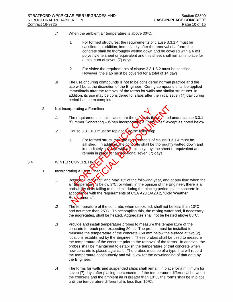
STRATFORD WPCP CLARIFIER UPGRADES AND Section 03300 STRUCTURAL REHABILIATION CAST-IN-PLACE CONCRETE Contract 16-9725 Page 10 of 15
.7 When the ambient air temperature is above 30ºC.
.1 For formed structures: the requirements of clause 3.3.1.4 must be satisfied. In addition, immediately after the removal of a form, the concrete shall be thoroughly wetted down and be covered with a 6 mil polyethylene sheet or equivalent and this sheet shall remain in place for a minimum of seven (7) days.
.2 For slabs: the requirements of clause 3.3.1.6.2 must be satisfied. However, the slab must be covered for a total of 14 days.
.8 The use of curing compounds is not to be considered normal practice and the use will be at the discretion of the Engineer. Curing compound shall be applied immediately after the removal of the forms for walls and similar structures. In addition, its use may be considered for slabs after the initial seven (7) day curing period has been completed.
.2 Not Incorporating a Formliner
.1 The requirements in this clause are the same as those noted under clause 3.3.1 “Summer Concreting – When Incorporating a Form Liner” except as noted below.
.2 Clause 3.3.1.6.1 must be replaced by the following:
.1 For formed structures: the requirements of clause 3.3.1.4 must be satisfied. In addition, the concrete shall be thoroughly wetted down and immediately covered with a 6 mil polyethylene sheet or equivalent and remain in place for an additional seven (7) days.
3.4 WINTER CONCRETING
.1 Incorporating a Form Liner
.1 Between October 1st and May 31st of the following year, and at any time when the air temperature is below 3ºC, or when, in the opinion of the Engineer, there is a probability of its falling to that limit during the placing period, place concrete in accordance with the requirements of CSA A23.1/A23.2, “Cold Weather Requirements”.
.2 The temperature of the concrete, when deposited, shall not be less than 10ºC and not more than 25ºC. To accomplish this, the mixing water and, if necessary, the aggregates, shall be heated. Aggregates shall not be heated above 85ºC.
.3 Provide and install temperature probes to measure the temperature of the concrete for each pour exceeding 20m3. The probes must be installed to measure the temperature of the concrete 150 mm below the surface at two (2) locations established by the Engineer. These probes shall be used to measure the temperature of the concrete prior to the removal of the forms. In addition, the probes shall be maintained to establish the temperature of that concrete when new concrete is placed against it. The probes must be of a type that will record the temperature continuously and will allow for the downloading of that data by the Engineer.
.4 The forms for walls and suspended slabs shall remain in place for a minimum for seven (7) days after placing the concrete. If the temperature differential between the concrete and the ambient air is greater than 10ºC, the forms shall be in place until the temperature differential is less than 10ºC.
FOR REFERENCE O
NLY
NOT OFFIC
IAL B
ID D
OCUMENT

STRATFORD WPCP CLARIFIER UPGRADES AND Section 03300 STRUCTURAL REHABILIATION CAST-IN-PLACE CONCRETE Contract 16-9725 Page 11 of 15
.5 The temperature difference between concrete being placed and the concrete
against which it is placed is of primary importance during winter concreting. The temperature of the base concrete, measured 150 mm below the contact surface, must be within 5ºC of the concrete being placed against it, but no lower than 5ºC. The Contractor, to satisfy this requirement, must provide a 5000 mm wide underslab heating system. This system must:
.1 Be continuous along the full length of the wall
.2 Heat the slab from bottom up.
.3 Include insulated tarpaulin placed on the slab over the area which is to be heated.
.4 Meet the above temperature requirements before the new concrete is placed.
.5 Be left in operation for at least 72 hours after the new concrete has been placed.
.6 Include the insulated tarpaulins being left in place over the heated area until the forms are removed.
.6 If uninsulated metal forms are to be used or if the temperature within the form falls below -5ºC prior to placing the concrete, an insulated cover must be provided over the formwork and heat must be provided to raise the temperature to +5ºC before pouring the concrete. All snow or ice must be removed from the form prior to placing the concrete. Insulated cover and heat must remain in place for the cure period.
.7 The temperature of the concrete shall be monitored and when the form is to be removed, the temperature differential between the concrete and the ambient conditions shall be recorded and:
.1 If the temperature differential is less than 10ºC and the winds is less than 20 km/h, no protection needs to be provided.
.2 If the temperature differential is 10ºC or greater, the concrete must be protected by insulated tarpaulins, placed over the concrete immediately after each section of formwork is removed, and tied down tightly around the concrete. This cover must remain in place for a minimum of seven (7) days.
.3 If the temperature differential is less than 10ºC but the wind is 20 km/h or greater, the concrete must be protected by insulated tarpaulins placed over the concrete immediately after each section of formwork is removed. The tarpaulin must be tied down and must be left in place for 24 hours.
.4 If the temperature differential is greater than 10ºC and the winds are 20 km/h or greater, the form must not be removed until the conditions meet the requirements of clauses 3.4.1.6.1 through 3.4.1.6.3.
.8 If an enclosure is required to meet the requirements of clauses 3.4.1.3 through 3.4.1.7, provide an enclosure.
.1 The enclosure shall be kept between 10ºC and 18ºC for a minimum period of seven (7) days after placing the concrete. The temperature
FOR REFERENCE O
NLY
NOT OFFIC
IAL B
ID D
OCUMENT

STRATFORD WPCP CLARIFIER UPGRADES AND Section 03300 STRUCTURAL REHABILIATION CAST-IN-PLACE CONCRETE Contract 16-9725 Page 12 of 15
shall be gradually reduced at the end of the period of protection at a rate not greater than 10ºC per day until the outside ambient temperature is reached.
.2 Combustion type heaters may be used but they shall be constructed and placed so that their combustion gases are not directed toward the surfaces of the “green” concrete.
.2 Not Incorporating a Form Liner
.1 The requirements in this clause are the same as those noted under clause 3.4.1 “Winter Concreting” for pours incorporating a form liner except as noted below.
.1 Clause 3.4.1.7.1 and 3.4.1.7.2 must be replaced with “If the temperature differential is less than 10ºC, the forms must be left on for seven (7) days and when they are removed, the concrete must be wetted down immediately and be covered tightly with a 10 mil polyethylene sheet or suitable new tarpaulin. The covering must remain in place for a minimum of seven (7) days”.
.2 Clause 3.4.1.7.1 must be replaced with “If the temperature differential is greater than 10ºC, under any wind conditions, the forms cannot be removed until ambient conditions meet the requirements of point 3.4.2.1.1 above. After those requirements are met, the actions described in that clause must be taken”.
3.5 VIBRATORS
.1 The use of mechanical vibrators is required for all structural concrete.
.2 A sufficient number of vibrators shall be employed so complete compaction is ensured.
.3 At least one (1) extra gasoline powered vibrator shall be on hand for emergency use.
.4 Vibration shall not be continued to the extent that water forms on the surface.
.5 Avoid any disturbance to concrete that has become too stiff to regain plasticity when vibrated.
.6 Vibration shall not be applied directly to steel which extends into partially hardened concrete.
3.6 CONSTRUCTION
.1 Do cast-in-place concrete work in accordance with CSA A23.1/A23.2.
.2 At construction joints, laitance must be mechanically removed from the face of concrete from previous castings before adjacent concrete is placed.
.3 Sleeves and Inserts:
.1 No sleeves, ducts, pipes, or other openings shall pass through joists, beams, column capitals or columns, except where indicated or approved by the Engineer.
.2 Where approved by the Engineer, set sleeves, ties, pipe hangers, and other inserts and openings as indicated or specified elsewhere. Sleeves and openings
FOR REFERENCE O
NLY
NOT OFFIC
IAL B
ID D
OCUMENT

STRATFORD WPCP CLARIFIER UPGRADES AND Section 03300 STRUCTURAL REHABILIATION CAST-IN-PLACE CONCRETE Contract 16-9725 Page 13 of 15
greater than 100 mm x 100 mm not indicated, must be approved by the Engineer.
.3 Do not eliminate or displace reinforcement to accommodate hardware. If inserts cannot be located as specified, obtain approval of modifications from the Engineer before placing of concrete.
.4 Check locations and sizes of sleeves and openings shown on drawings.
.5 Sleeves and openings shall be placed at a minimum of three sleeve diameters centre to centre unless noted otherwise.
.4 Anchor Bolts:
.1 Set anchor bolts to templates under supervision of appropriate trade prior to placing concrete.
.2 Protect anchor bolt holes from water accumulations, snow, and ice build-ups.
.3 When using proprietary anchor systems set bolts and fill holes with epoxy grout, in accordance with the manufacturer’s requirements. All proprietary anchors must be approved by the Engineer.
.4 Locate anchor bolts used in connection with expansion shoes, rollers, and rockers with due regard to ambient temperature at time of erection.
.5 Under special circumstances, with approval of the Engineer, grouted anchor bolts may be installed into preformed holes or holes drilled after concrete has set. Formed holes or sleeves to be minimum 100 mm diameter and be deformed.
.5 Drainage Holes and Weep Holes:
.1 Form weep holes and drainage holes in accordance with Section 03100 – Concrete Forms and Accessories. If wood forms are used, remove them after concrete has set.
.2 Install weep hole tubes and drains as indicated.
.6 Coordination:
.1 Adjust the work to suit final shop drawings of the equipment being supplied. Verify all sizes with the trade supplying and installing the equipment. Obtain, utilize and submit data on relevant sizes to suit any change in equipment. Confirm the adjustments with the Engineer.
.7 Grouting:
.1 Grout to be place in accordance with grout specification section 03600. Grout under base plates and/or machinery using procedures in accordance with manufacturer’s recommendations that result in 100 percent contact over grouted area. Install bleed holes in base plates to ensure full coverage of grout.
.8 Slip-Sheet:
.1 Install 10 mil polyethylene slip-sheet under mud-slab for all the concrete slabs-on-grade as indicated on the drawings.
FOR REFERENCE O
NLY
NOT OFFIC
IAL B
ID D
OCUMENT

STRATFORD WPCP CLARIFIER UPGRADES AND Section 03300 STRUCTURAL REHABILIATION CAST-IN-PLACE CONCRETE Contract 16-9725 Page 14 of 15
.2 Lap slip-sheet a minimum of 300mm at joints and seal.
.3 Seal punctures in dampproof membrane before placing concrete. Use patching material at least 300 mm larger than puncture and seal.
.9 Walls:
.1 A grout starter, 100 mm thick minimum, layer must be provided at the base of all walls.
3.7 FINISHES
.1 Formed finishes specified herein shall be finished as defined by CSA A23.1/A23.2.
.1 The surfaces exposed to view shall be given a “sack-rubbed finish”, except where a controlled permeability formliner is specified.
.2 The surfaces exposed to potable water, including the portion of those structures above the high water level to the top of the structure, shall be given a “sack-rubbed” finish, except where a controlled permeability formliner is specified.
.3 All buried surfaces shall be given a rough form finish, except where a controlled permeability formliner is specified.
.4 All exposed and non-exposed corners shall be rubbed with a carborundum stone to remove any loose concrete and to create a smooth and rounded profile.
.2 Unformed surfaces shall be finished as defined by CSA A23.1/A23.2.
.1 The floor surface of occupied spaces shall be “floated” and “trowelled” to create a Class A Floor finish as defined by Table 21 in CSA A23.1/A23.2.
3.8 EXAMINATION OF COMPLETED STRUCTURES
.1 Undertake, with the Engineer, review of concrete surfaces for defects and finishes.
.2 Undertake, with the Engineer, assessments and measurements of the concrete structures for cracking.
.3 Provide a written summary of defects noted complete with a plan showing locations of each defect.
.4 Submit a plan for repair of each defect in accordance with these specifications.
.5 Undertake, with the Engineer, to test all liquid retaining structures for water tightness in accordance with applicable standards.
.6 Test for water tightness in accordance with ACI 350.1M. All chambers, channels, and tanks to be tested separately as open containment structures classified as “Other types”.
3.9 PATCHING OR REPAIRS
.1 No patching or repairing shall be carried out without the approval of the Engineer.
FOR REFERENCE O
NLY
NOT OFFIC
IAL B
ID D
OCUMENT
STRATFORD WPCP CLARIFIER UPGRADES AND Section 03300 STRUCTURAL REHABILIATION CAST-IN-PLACE CONCRETE Contract 16-9725 Page 15 of 15
.2 All honeycomb, chips, spalls, or suspected honeycomb in new concrete work shall be
chipped out and repaired.
.3 Repairs of new concrete shall meet the requirements of specification 03905 Concrete Repairs.
.4 All visible cracks in liquid retaining structures shall be repaired prior to leak testing. Submit a detailed plan and details for review by Engineer before beginning any repair or injection. As the standard repair methodology, unless otherwise approved by the Engineer, cracks shall be injected with epoxy. Clean face of concrete after injection is complete.
.5 If first injection is not successful, repeat procedure until all visible leaks are repaired.
.6 During the leak test, minor visibly leaking cracks may be repaired with polyurethane grout upon approval of the Engineer.
.7 In the event that injection cannot seal the leak, with the approval of the Engineer, the crack shall:
.1 be routed out square to a depth and width of 20 mm
.2 be thoroughly cleaned
.3 have a bond breaker placed in the bottom of the routed slot
.4 be primed in accordance with the manufacturers recommendations
.5 be sealed with a polyurethane sealant such as Sikaflex 2C NS EZ Mix by Sika Canada, or approved equal.
.6 Sealant shall be allowed to cure in accordance to the manufacturers written procedures.
.7 The floor surface of exterior or interior walkways and tankage or chambers, not included in point No. 1 above, shall be “swirl trowelled” to create a non-slip surface.
3.10 SITE TOLERANCES
.1 Concrete tolerance in accordance with CSA A23.1/A23.2.
.2 The Contractor shall survey the site and shall provide a drawing layout of the concrete work to be included in the “as built” drawings.
END OF SECTION
FOR REFERENCE O
NLY
NOT OFFIC
IAL B
ID D
OCUMENT

FOR REFERENCE O
NLY
NOT OFFIC
IAL B
ID D
OCUMENT

STRATFORD WPCP CLARIFIER UPGRADES AND Section 03600 STRUCTURAL REHABILIATION GROUT Contract 16-9725 Page 1 of 2
1 GENERAL
1.1 SCOPE
.1 This section covers procurement and installation of grout beneath column base plates and other structural uses of grout as indicated on the drawings. Unless otherwise specified, only non-shrinking grout shall be furnished.
.2 Epoxy grouting of anchor bolts, threaded rod anchors and reinforcing bars are covered in the Anchorage in Concrete section.
1.2 SUBMITTALS
.1 A letter of certification indicating the types of grout to be supplied and the intended use of each type shall be submitted in accordance with the Section 01330 – Submittal Procedures.
1.3 DELIVERY, STORAGE AND HANDLING
.1 Materials shall be handled, transported and delivered in a manner that will prevent damage of any kind. Materials shall be protected from moisture.
2 PRODUCTS
2.1 MATERIALS
.1 Non-shrinking Grout: cementitious grout with demonstrated non-shrinking properties; L&M “Crystex”, Master Buildings “Masterflow 928” or “Set Grout”, Sauereisen “F-100 Level Fill Grout”, Sonneborn “Sonogrout 10K”, or Five Star Products “Five Star Grout”.
.2 Water: Clean and free from deleterious substances.
.3 Min 28 Day Compressive Strength: 50MPa
.4 Aggregate: where required due to the thickness of the grout extends with aggregate in accordance with the manufacturers written recommendations.
2.2 NON-SHRINKING GROUT
.1 Non-shrinking grout shall be furnished factory pre-mixed so that only water is added at the job site.
3 EXECUTION
3.1 PREPARATION
.1 The concrete foundation to receive non-shrinking grout shall be saturated with water for at least 12 hours preceding grouting unless additional time is required by the grout manufacturer.
3.2 INSTALLATION
.1 Mixing
.1 Grout shall be mixed in a mechanical mixer. No more water shall be used than is necessary to produce a flowable grout.
FOR REFERENCE O
NLY
NOT OFFIC
IAL B
ID D
OCUMENT

STRATFORD WPCP CLARIFIER UPGRADES AND Section 03600 STRUCTURAL REHABILIATION GROUT Contract 16-9725 Page 2 of 2
.2 Placement
.1 Unless otherwise specified or indicated on the drawings, grout under base plates shall be 38 mm thick. Grout shall be placed in strict accordance with the directions of the manufacturer so that all spaces and cavities below the base plates are completely filled without voids. Forms shall be provided where structural components of base plates will not confine the grout.
.3 Edge Finishing
.1 In all locations where the edge of the grout will be exposed to view, the grout shall be finished smooth after it has reached its initial set. Except where shown to be finished on a slope, the edges of grout shall be cut off flush at the base plate.
.4 Curing
.1 Non-shrinking grout shall be protected against rapid loss of moisture by covering with wet clothes or polyethylene sheets. After edge finishing is completed, the grout shall be wet cured for at least three (3) days and then an acceptable membrane curing compound shall be applied.
END OF SECTION
FOR REFERENCE O
NLY
NOT OFFIC
IAL B
ID D
OCUMENT

STRATFORD WPCP CLARIFIER UPGRADES AND Section 03800 STRUCTURAL REHABILIATION POLYURETHANE INJECTION Contract 16-9725 Page 1 of 4
1 GENERAL
1.1 SCOPE OF WORK
.1 Furnish all labour, materials, tools and equipment and perform all operations necessary for the repair of leaking construction joints or cracks in concrete using polyurethane injection resin.
1.2 RELATED SECTIONS
.1 In addition to the general project requirements in Division 1, the following sections are referenced in this section:
.1 Section 03300 Cast-in-Place Concrete
.2 Section 07900 Joint Sealers
1.3 QUALITY ASSURANCE
.1 In addition to the requirements of 01450 – Quality Control, the following measures are required:
.1 The applicator shall have a minimum of three (3) years of experience performing similar work and be authorized by the supplier for performing polyurethane resin injection of the nature specified.
.2 A technical specialist representing the product supplier shall visit the site to examine site specific conditions and to make recommendations regarding material selection, injection equipment and application techniques.
1.4 SUBMITTALS
.1 General:
.1 Applicator shall submit certificate authorized by the supplier for performing polyurethane resin injection of the nature specified.
.2 Prior to start of work, discuss with engineer the type and location of crack repairs.
.3 Submit a work plan indicating the materials and method of preparation, repair, and clean up.
.2 Product Data:
.1 Submit manufacturer’s data and application instructions for each product specified
1.5 DELIVERY, STORAGE AND HANDLING
.1 All materials shall be delivered to the site in undamaged, unopened containers bearing the supplier’s original labels. Store materials in protected location prior to use, in accordance with manufacturer’s directions.
1.6 ENVIRONMENTAL AND SITE CONDITIONS
FOR REFERENCE O
NLY
NOT OFFIC
IAL B
ID D
OCUMENT

STRATFORD WPCP CLARIFIER UPGRADES AND Section 03800 STRUCTURAL REHABILIATION POLYURETHANE INJECTION Contract 16-9725 Page 2 of 4
.1 Environmental Conditions
.1 Workplace Hazardous Materials Information System (WHMIS) labels on all containers shall conform to Canadian regulations, proper chemical name, shipping class, packing group and UN number.
.2 Material Safety Data Sheets (MSDS) for all materials shall conform to Canadian regulations.
.3 No materials shall be used that are manufactured from or contain toluene diisocyanate (TDI), toluene, acetone or methyl ethyl ketone.
.4 No materials shall be used that are flammable or that display shipping Class 3 Red warning labels.
.2 Workplace Safety
.1 Supply workmen with appropriate safety equipment for performing high-pressure injection of polyurethane resins and associated tasks.
.2 Supply safety devices, traffic control barriers, drop sheets and other items to protect the site, other contents and other personnel from contact with the Contractor’s material or equipment.
1.7 SITE SERVICES
.1 The Contractor shall attend the site and evaluate the present electrical supply that is available for their use. The Contractor will be responsible to modify those services, if required, without affecting the pumping operations and to restore those services after the work is complete. As an alternative, the Contractor can supply their own power source but must control the noise to the satisfaction of the Owner.
.2 All construction debris and empty containers are to be removed from the site by the Contractor and disposed of in accordance with applicable regulations.
2 PRODUCTS
2.1 APPROVED MANUFACTURERS
.1 Multiurethanes, 5245 Creekbank Rd, Mississauga, Ontario, Canada, L4W 1N3, Phone: 905-564-7650, URL: www.multiurethanes.com
.2 Sika Canada Inc., 601 Delmar Ave., Pointe-Claire, Quebec, Canada, H9R 4A9, Phone: 1-800-933-4758, URL: www.sika.ca
.3 BASF Corporation Construction Systems, 889 Valley Park Drive, Shakopee, MN, USA, 55379, Phone: 1-800-433-9517, URL: www.basf.ca
2.2 MATERIALS
.1 Active Leaking Cracks
.1 Polyurethane injection resins for actively leaking joints shall conform with the following specifications:
.1 Water activated type
FOR REFERENCE O
NLY
NOT OFFIC
IAL B
ID D
OCUMENT
STRATFORD WPCP CLARIFIER UPGRADES AND Section 03800 STRUCTURAL REHABILIATION POLYURETHANE INJECTION Contract 16-9725 Page 3 of 4
.2 Flexible foam end product
.3 Hydrophobic
.4 Solvent-free and non-flammable
.5 Fast-acting with variable cure rate
.6 Cured product shall not shrink
.7 MDI-based polyurethane pre-polymer with accelerator
.8 Suitable for cold temperature use above 4°C
.9 Viscosity – 600 cps at 20°C
.2 Acceptable product meeting this specification:
.1 Multi-urethanes Flexible Resin.
.2 SikaFix PU LV
.3 BASF MasterInject 1230 IUG
3 EXECUTION
3.1 DRILLING INJECTION HOLES
.1 Drill 9 mm injection holes at an angle of 45 degrees to intersect joints beyond the mid-point of the wall or slab being injected.
.2 Drill hole spacing shall not exceed 300 mm under any condition.
.3 All drill holes shall be flushed with copious quantities of water to remove all dust and drilling debris from the hole prior to installing the injection packers.
3.2 INSTALLING INJECTION PACKERS
.1 Install 9.5 mm plastic injection packers, complete with metal fittings, in accordance with supplier’s instructions.
3.3 FLUSHING CRACKS PRIOR TO INJECTION
.1 Flush cracks with potable water prior to proceeding with injection of polyurethane resin.
.2 Acid flush is required. Use crack flushing agent diluted to a 5 percent solution in water and flush with copious quantities of water following acid injection
3.4 INSTALLATION OF SEALING MATERIALS
.1 Install appropriate sealing materials along the crack or joint to be injected, where required, to minimize the loss of polyurethane injection resin.
.2 Suitable sealing materials may include hydraulic cement, epoxy bonders, polyester bonders, wooden shims, grout pads or back rod, depending on site conditions.
FOR REFERENCE O
NLY
NOT OFFIC
IAL B
ID D
OCUMENT
STRATFORD WPCP CLARIFIER UPGRADES AND Section 03800 STRUCTURAL REHABILIATION POLYURETHANE INJECTION Contract 16-9725 Page 4 of 4
3.5 INJECTION EQUIPMENT
.1 Use an electrically-operated airless pump, modified specifically for polyurethane resin injection.
.2 The pump shall be equipped with gravity feed suction containers.
.3 The pump controls shall feature an adjustable pressure and to provide automatic on/off pump operation.
.4 A multiple grout header shall be used to control the flow of polyurethane resin and shall include a 0-2 MPa pressure gauge, flow control valves and a bypass pressure relief valve.
3.6 MIXING AND HANDLING OF INJECTION RESINS
.1 Follow recommended guidelines as per supplier’s product data sheets.
.2 Measure all materials using graduated containers and in appropriate quantities to suit site requirements.
3.7 INJECTION OF POLYURETHANE RESINS
.1 Follow recommended guidelines as per supplier’s product data sheets and technical literature.
.2 Start injection procedure from the bottom of a crack and inject until resin can be seen in the next port above, then move to that port and inject.
.3 Inject sufficient polyurethane resin at each location to completely fill all cracks, and injection material can be seen in the adjacent port.
.4 If unusually large quantities of material are required, there may be honeycomb or other structural issues present, please contact the engineer before proceeding.
.5 Avoid the use of excessive injection pressures.
.6 Continue injection until a permanent watertight barrier has been created.
3.8 CLEAN-UP
.1 Remove all injection packers, plug and repair opening and leave in condition ready for coating.
END OF SECTION
FOR REFERENCE O
NLY
NOT OFFIC
IAL B
ID D
OCUMENT

STRATFORD WPCP CLARIFIER UPGRADES AND Section 03905 STRUCTURAL REHABILIATION CONCRETE REPAIRS Contract 16-9725 Page 1 of 3
1 GENERAL
1.1 SCOPE OF WORK
.1 Preparation, repair and curing of concrete repairs inside the clarifiers and valve chambers.
.2 Repairs of any newly placed concrete.
.3 Repairs of newly placed concrete will not be costed under this section but considered incidental and included in the cost of the new work.
1.2 RELATED SECTIONS
.1 Section 03300 Cast in Place Concrete
.2 Section 03800 Polyurethane Injections
1.3 BASIS OF PAYMENT
.1 Payment of this item shall be based on the lump sum price bid.
1.4 QUALITY ASSURANCE
.1 Pre-concrete meeting: hold a meeting prior to start of work to discuss the work plan. Attendants must include but not be limited to Engineer, repair foreman, general contractor.
1.5 SUBMITTALS
.1 Make all submittals in accordance with Section 1330.
.2 Work plan: Prior to the start of work, submit the methods of preparation, repair, and curing and a list of repair locations.
.3 Product data: provide product data complete with MSDS, technical data sheets and application manuals.
1.6 WARRANTY
.1 Provide a warranty for 5 years after substantial completion that the repairs will not have debonded, chipped or popped, and that the tanks and chambers will remain leak free, combined manufacturers and contractor’s warranty.
2 PRODUCTS
2.1 MATERIALS
.1 Expansion Joint Repair
.1 Inject joint to displace and stop flowing water coming through the joint, forming a tough flexible foam seal. See specification 3800 Polyurethane Injection.
.2 Polyurethane-based elastomeric sealant; Multi Component sealant as per Section 07900 Joint Sealers.
FOR REFERENCE O
NLY
NOT OFFIC
IAL B
ID D
OCUMENT

STRATFORD WPCP CLARIFIER UPGRADES AND Section 03905 STRUCTURAL REHABILIATION CONCRETE REPAIRS Contract 16-9725 Page 2 of 3
.2 Crack Repair
.1 Inject joint to displace and stop flowing water coming through the joint, forming a tough flexible foam seal. See specification 3800 Polyurethane Injection.
.3 Spall Repair
.1 Water-based epoxy resin to protect against corrosion and assist as bonding agent
.1 Sika: SikaTop Armatec 110 EpoCem
.2 High-performance, non-shrink, cementitious grout
.1 Sika: SikaGrout 212 HP
3 EXECUTION
3.1 GENERAL
.1 All preparation and repair techniques should be in accordance with the International Concrete Repair Institute (ICRI).
3.2 SURFACE PREPARATION
.1 No patching or repairing shall be carried out without the approval of the ENGINEER.
.2 All repair areas shall be chipped out to sound concrete as indicated on the drawings. The edge around the perimeter of the area shall be saw-cut vertically to a depth of 20 mm minimum to eliminate all “feather” edges of the repair product. If repair extends to the depth of the reinforcement, the chipping shall be continued to a depth of 1.4 times the diameter of the largest reinforcing bar or 40 mm minimum beyond the layer of reinforcement.
.3 Chips and edge breaks in the concrete shall be repaired as noted above.
.4 Joints shall have all deteriorated concrete that is unsatisfactory as a base for new joint sealant removed.
.5 Expose all areas of deterioration by removing damaged concrete and water/grit blasting or grinding on the entire repair surface.
.6 Remove all spent grit and debris from the floor and surrounding area.
.7 No dirt/debris shall be allowed to enter the floor drains. An approved filter fabric shall be fastened securely over the drains and shall be maintained clean throughout the work.
.8 Wash down the surfaces blasted with a spray water jet, starting from the top, to remove all dust and debris from the joints and the surface of the repairs.
3.3 ENVIRONMENTAL CONDITIONS
.1 Surfacing:
.1 Patching shall only be applied in sufficient quantity to allow complete filling of the spalled or honeycombed areas in accordance with the manufacturer’s requirements.
FOR REFERENCE O
NLY
NOT OFFIC
IAL B
ID D
OCUMENT

STRATFORD WPCP CLARIFIER UPGRADES AND Section 03905 STRUCTURAL REHABILIATION CONCRETE REPAIRS Contract 16-9725 Page 3 of 3
.2 Cure according to the requirements of the manufacturer.
3.4 APPLICATION
.1 Bonding agent shall be scrubbed in to the repair area, and any exposed reinforcement shall be coated.
.2 Repair Mortar is to be extended with stone in accordance with the manufacturer’s instructions when the depth of the repair is beyond 125mm.
.3 Repair mortar shall be mixed so that it does not sag or flow when applied on vertical surfaces.
.4 The mortar surface shall be steel trowel finished to a uniform, consistent, smooth and even profile and to a quality.
.5 The mortar surface shall be cured by immediately covering the repair with polyurethane film and sealing the edges. Cure shall be as defined by the manufacturer, and a minimum of 3 days.
3.5 POST APPLICATION
.1 The patch shall be continuously covered with a 6 mil polyethylene sheet and heated to above 15ºC for 14 days.
END OF SECTION
FOR REFERENCE O
NLY
NOT OFFIC
IAL B
ID D
OCUMENT

FOR REFERENCE O
NLY
NOT OFFIC
IAL B
ID D
OCUMENT

STRATFORD WPCP CLARIFIER UPGRADES AND Division 5 STRUCTURAL REHABILITATION METALS
Contract 16-9725
DIVISION 5 – METALS
FOR REFERENCE O
NLY
NOT OFFIC
IAL B
ID D
OCUMENT

FOR REFERENCE O
NLY
NOT OFFIC
IAL B
ID D
OCUMENT

STRATFORD WPCP CLARIFIER UPGRADES AND Division 5 STRUCTURAL REHABILITATION METALS
Contract 16-9725 Table of Contents
DIVISION 5 – METALS
Section No. 1 TITLE
05500 Metal Fabrications
05510 Metal Stairs and Ladders
05550 Anchorage in Concrete
FOR REFERENCE O
NLY
NOT OFFIC
IAL B
ID D
OCUMENT

FOR REFERENCE O
NLY
NOT OFFIC
IAL B
ID D
OCUMENT

STRATFORD WPCP CLARIFIER UPGRADES AND Section 05500 STRUCTURAL REHABILIATION METAL FABRICATIONS Contract 16-9725 Page 1 of 4
1 GENERAL
1.1 SCOPE OF WORK
.1 Design, supply and install the following items including bolts, nuts, washers, anchors, hardware,
.1 Lintels, concrete protection angles, embedded grating supports
.2 Checkered plate covers and supports
.3 All other miscellaneous metal items shown on the drawings.
1.2 RELATED SECTIONS
.1 Section 01330 - Submittals
.2 Section 03300 - Cast-in-Place Concrete
.3 Section 05510 - Metal Stairs and Ladders
1.3 REFERENCES
.1 All products shall conform to the following standards and regulations:
.2 ASTM International (ASTM).
.1 ASTM A53/A53-12 - Specification for Pipe, Steel, Black and Hot-Dipped, Zinc-Coated Welded and Seamless
.2 ASTM A123/A123M-13 - Standard Specification for Zinc (Hot-Dip Galvanized) Coatings on Iron and Steel Products
.3 ASTM A276/A276M-15 - Standard Specification for Stainless Steel Bars and Shapes
.4 ASTM A307-14 - Standard Specification for Carbon Steel Bolts, Studs, and Threaded Rod 60000 psi Tensile Strength
.5 ASTM D1187/D1187M - 97(2011)e1 - Standard Specification for Asphalt-Base Emulsions for Use as Protective Coatings for Metal
.6 ASTM D5360-09 – Standard Practice for Design and Construction of Bituminous Surface Treatment
.7 ASTM D6511/D6511M-06(2011)e1 - Standard Test Methods for Solvent Bearing Bituminous Compounds
.3 Canadian Standards Association (CSA):
.1 CSA G40.20-13/G40.21-13 - General Requirements for Rolled or Welded Structural Quality Steel / Structural Quality Steel
.2 CAN/CSA S16-14 - Design of Steel Structures
FOR REFERENCE O
NLY
NOT OFFIC
IAL B
ID D
OCUMENT

STRATFORD WPCP CLARIFIER UPGRADES AND Section 05500 STRUCTURAL REHABILIATION METAL FABRICATIONS Contract 16-9725 Page 2 of 4
.3 CAN/CSA S157-05/S157.1-05 (R2015) - Strength Design in Aluminum /
Commentary on CSA S157-05, Strength Design in Aluminum
.4 CSA W48-14 - Filler Metals and Allied Materials for Metal-Arc Welding
.5 CSA W59.2-M1991 (R2013) - Welded Aluminum Construction
.6 CSA W59-13 - Welded Steel Construction (Metal-Arc Welding)
1.4 SHOP DRAWINGS
.1 Submit shop drawings in accordance with Section 01330 – Submittals.
.2 Indicate materials, core thicknesses, finishes, connections, joints, method of anchorage, number of anchors, supports, reinforcement, details and accessories.
.3 In preparing shop drawings, the fabricator shall verify that all component parts and assembly of each item will support the superimposed loads without deflection detrimental to function, appearance or safety.
.4 Provide drawings certified by a professional engineer registered in Ontario.
1.5 PROTECTION
.1 Cover exposed stainless steel surfaces with pressure sensitive heavy protection paper or apply strippable plastic coating, before shipping to job site.
.2 Leave protective covering in place until final cleaning of building. Provide instructions for removal of protective covering.
2 PRODUCTS
2.1 MATERIALS
.1 Welding materials: to CSA W59 for Steel and CSA W59.2 for Aluminum.
.2 Welding electrodes: to CSA W48 Series.
.3 Bolts and anchor bolts: SS304
.4 Aluminum shall conform to the following alloy designations of the Aluminum Association:
.1 Extruded Shapes – Structural: 6061-T6.
.2 Smooth Plates: 5083-H34.
.3 Rivets and Bolts: 6061-T6.
.4 Checkered or Tread Plate: 6061-T6.
.5 All stainless steel: to ASTM A276, Type 316
.6 Grout: non-shrink, non-metallic, flowable, 24h, 15 MPa at 24 hours, pull-out strength 7.9 MPa.
2.2 FABRICATION
FOR REFERENCE O
NLY
NOT OFFIC
IAL B
ID D
OCUMENT

STRATFORD WPCP CLARIFIER UPGRADES AND Section 05500 STRUCTURAL REHABILIATION METAL FABRICATIONS Contract 16-9725 Page 3 of 4
.1 Fabricate work square, true, straight and accurate to required size, with joints closely
fitted and properly secured.
.2 Use self-tapping shake-proof screws on items requiring assembly by screws or as indicated.
.3 Where possible, fit and shop assemble work, ready for erection.
.4 Ensure exposed welds are continuous for length of each joint. File or grind exposed welds smooth and flush.
2.3 FINISHES
.1 Galvanizing: hot-dipped galvanizing with zinc coating 610 g/m2 to ASTM A123M.
.2 Zinc primer: zinc rich, ready mix in accordance with Section 9900 Painting.
.3 Bituminous Paint: quick-drying asphalt utility enamel.
2.4 ISOLATION COATING
.1 Isolate aluminum from following components, by means of bituminous paint:
.1 Dissimilar metals except stainless steel, zinc or white bronze of small area.
.2 Concrete, mortar and masonry.
.3 Wood.
2.5 PLATFORM FRAMING
.1 All aluminum angles, channels, beams and related connection hardware as indicated.
2.6 CHECKER PLATES AND FRAMES
.1 Plates shall be provided with welded ribs as required to limit deflection of any plate to 1/240th of the span under a concentrated load of 1.0 kN at the centre or 4.8 kPa uniform live loading unless noted otherwise.
.2 All checker plates shall be approved ‘raised’ patterns and the edges of all plates shall be planed to a straight edge. The minimum thickness of plates shall be 6 mm.
.3 Checker plates, when not detailed, shall be designed, subdivided and fastened as to be readily removable. Where cut, abutting edges shall have continuity of pattern.
.4 The angle frames and border bars shall have mitred corners neatly fitted and welded. Border bars shall be fastened to angle frames by welding.
.5 Checker plates shall be fabricated in panels that can be easily handled by plant personnel. Unless otherwise indicated on the drawings, the weight of individual panels shall not exceed 35 kg.
.6 Panels shall be within 6 mm of authorized length and 6 mm of authorized width, and shall have a maximum difference in length of opposite diagonals of 6 mm.
.7 After installation, there shall be not more than 6 mm clearance between panels.
FOR REFERENCE O
NLY
NOT OFFIC
IAL B
ID D
OCUMENT

STRATFORD WPCP CLARIFIER UPGRADES AND Section 05500 STRUCTURAL REHABILIATION METAL FABRICATIONS Contract 16-9725 Page 4 of 4
2.7 PIPE “GRAB” BARS
.1 Stainless steel or aluminum pipe: 50 mm nominal outside diameter, formed to shapes and sizes as indicated on drawings.
2.8 SLAB CORNER GUARDS
.1 Galvanized steel angle as indicated.
2.9 MISCELLANEOUS ITEMS
.1 Review all drawings and include all other metal fabrication not included in the above noted list.
3 EXECUTION
3.1 ERECTION
.1 Do welding work in accordance with CSA W59, unless specified otherwise.
.2 Erect metal work square, plumb, straight and true, accurately fitted with tight joints and intersections.
.3 Provide suitable means of anchorage acceptable to engineer such as dowels, anchor clips, bar anchors, expansion bolts and shields, chemically anchored bolts and toggles.
.4 Exposed fastening devices to match finish and be compatible with material through which they pass.
.5 Provide components for building by other sections in accordance with shop drawings and schedule.
.6 Make field connections with bolts to CAN/CSA S16 or weld.
.7 Hand items over for casting into concrete to appropriate trades together with setting templates.
.8 Touch-up rivets, field welds, bolts and burnt or scratched surfaces after completion of erection with primer.
.9 Touch-up galvanized surfaces with zinc rich primer where burned by field welding.
END OF SECTION
FOR REFERENCE O
NLY
NOT OFFIC
IAL B
ID D
OCUMENT

STRATFORD WPCP CLARIFIER UPGRADES AND Section 05510 STRUCTURAL REHABILIATION METAL STAIRS AND LADDERS Contract 16-9725 Page 1 of 3
1 GENERAL
1.1 RELATED SECTIONS
.1 Section 01330 – Submittals
.2 Section 03300 – Cast-in-Place Concrete
.3 Section 05500 – Metal Fabrication
1.2 REFERENCE STANDARDS
.1 American Society for Testing and Materials (ASTM):
.1 ASTM A123/A123M-13 - Standard Specification for Zinc (Hot-Dip Galvanized) Coatings on Iron and Steel Products
.2 ASTM A276/A276M-15 - Standard Specification for Stainless Steel Bars and Shapes
.3 ASTM A307-14 - Standard Specification for Carbon Steel Bolts, Studs, and Threaded Rod 60000 psi Tensile Strength
.4 ASTM A53/A53M-12 - Specification for Pipe, Steel, Black and Hot-Dipped, Zinc-Coated Welded and Seamless
1.3 SHOP DRAWINGS
.1 Submit engineered and certified shop drawings in accordance with Section 01330 – Submittals.
.2 Indicate construction details, sizes of aluminum and/or steel sections and thickness of aluminum and/or steel sheets.
2 PRODUCTS
2.1 MATERIALS
.1 Steel sections: to CSA G40.21, Grade 350W.
.2 Steel plate: to CSA G40.21, Grade 300W.
.1 Pattern: checkered.
.3 Floor plate: to CSA G40.21, Grade 300W.
.1 Thickness: 6 mm, reinforced as necessary to suit design loading.
.2 Width: 1200 mm maximum.
.3 Design: 4.8 kPa.
.4 Steel pipe: to ASTM A53/A53M, standard weight, schedule 40, seamless black.
.5 Steel tubing: to CSA G40.21, Grade 350W, sizes and dimensions as indicated.
FOR REFERENCE O
NLY
NOT OFFIC
IAL B
ID D
OCUMENT

STRATFORD WPCP CLARIFIER UPGRADES AND Section 05510 STRUCTURAL REHABILIATION METAL STAIRS AND LADDERS Contract 16-9725 Page 2 of 3
.6 Metal bar grating: to ANSI/NAAMM MBG 531, steel, Type W-19-4, with abrasive
nosings.
.7 Welding materials: to CSA W59.
.8 Bolts: to ASTM A307.
.9 Aluminum shall conform to the following allowable designations of the Aluminum Association:
Extruded Shapes – Structural 6061-T6
Smooth Plates 5083-H34
Rivets and Bolts 6061-T6
Checkered or Tread Plate 6061-T6
Castings 356-T2
Hand Railing (clear anodized) 6351-T6
.10 All stainless steel to ASTM A276, Type 316.
2.2 FABRICATION
.1 Weld connections where possible, otherwise bolt connections. Countersink exposed fastenings, cut off bolts flush with nuts. Make exposed connections of same material, colour and finish as base material on which they occur.
2.3 PIPE TUBING BALUSTRADES
.1 Construct balusters and handrails from steel or aluminum tubing, as indicated.
.2 Cap and weld exposed ends of balusters and handrails.
.3 Terminate at abutting wall with end flange.
2.4 LADDERS
.1 Stainless steel or aluminium ladders and related hardware as shown on the drawings.
.2 Stainless steel or aluminium “grab” bars as shown on the drawings.
2.5 FINISHES
.1 Aluminum shall be clear anodized.
3 EXECUTION
3.1 INSTALLATION
.1 Install plumb and true in exact locations, using welded connections wherever possible to provide rigid structure. Provide anchor bolts, bolts and plates for connecting ladder to structure.
FOR REFERENCE O
NLY
NOT OFFIC
IAL B
ID D
OCUMENT

STRATFORD WPCP CLARIFIER UPGRADES AND Section 05510 STRUCTURAL REHABILIATION METAL STAIRS AND LADDERS Contract 16-9725 Page 3 of 3
.2 Hand items over for casting into concrete or building into concrete to appropriate trades,
together with setting templates.
END OF SECTION
FOR REFERENCE O
NLY
NOT OFFIC
IAL B
ID D
OCUMENT

FOR REFERENCE O
NLY
NOT OFFIC
IAL B
ID D
OCUMENT

STRATFORD WPCP CLARIFIER UPGRADES AND Section 05550 STRUCTURAL REHABILIATION ANCHORAGE IN CONCRETE Contract 16-9725 Page 1 of 6
1 GENERAL
1.1 RELATED SECTIONS
.1 Comply with requirements of Division 1.
1.2 SCOPE
.1 This section covers the procurement and installation of anchors in concrete. It includes cast-in-place anchor bolts, adhesive anchors, expansion anchors and epoxy grouted anchor bolts and reinforcing steel to be installed in concrete.
1.3 GENERAL
.1 Unless otherwise specified or indicated on the drawings, all anchors and anchor bolts shall be cast-in-place anchor bolts with forged heads or embedded nuts and washers. Unless otherwise indicated, bolts in concrete shall have a diameter of at least 20 mm.
.2 Unless otherwise indicated on the drawings, anchors and anchor bolts used in the following locations and applications shall be of the indicated materials. Other anchors and anchor bolts shall be as indicated on the drawings. Where stainless steel is indicated, use type 316 stainless steel.
.1 Cast-in-Place Anchor Bolts:
.2 Submerged locations: Stainless steel
.3 Locations subject to splashing: Stainless steel
.4 Buried locations: Stainless steel
.5 Anchorage of structural steel columns: Galvanized steel
.3 Threaded Rod and Expansion Anchors:
.1 Submerged locations: Stainless steel
.2 Locations subject to splashing: Stainless steel
.3 Buried locations: Stainless steel
.4 Anchorage of structural steel columns: Stainless steel
.5 Other exterior locations: Stainless steel
.4 Adhesive anchors may be used instead of cast-in-place anchors where specifically indicated or permitted on the drawings or with the specific acceptance by the Engineer.
1.4 SUBMITTALS
.1 Letters of certification indicating the manufacturer and types of adhesive anchors, and epoxy grouts to be supplied shall be submitted in accordance with Section 01330 – Submittal Procedures.
1.5 REFERENCES
FOR REFERENCE O
NLY
NOT OFFIC
IAL B
ID D
OCUMENT

STRATFORD WPCP CLARIFIER UPGRADES AND Section 05550 STRUCTURAL REHABILIATION ANCHORAGE IN CONCRETE Contract 16-9725 Page 2 of 6
.1 Canadian Standards Association (CSA):
.1 CAN/CSA-G30.18-09 (2014) - Carbon Steel Bars for Concrete Reinforcement
.2 American Society for Testing and Materials (ASTM):
.1 ASTM A307-14 - Standard Specification for Carbon Steel Bolts, Studs, and Threaded Rod 60000 psi Tensile Strength
.2 ASTM F593-13a - Standard Specification for Stainless Steel Bolts, Hex Cap Screws, and Studs
.3 ASTM F594-09e1 - Standard Specification for Stainless Steel Nuts
.4 ASTM A153/A153M-09 - Standard Specification for Zinc Coating (Hot-Dip) on Iron and Steel Hardware
.5 ASTM A385/A385M-11e1 - Standard Practice for Providing High-Quality Zinc Coatings (Hot-Dip)
.3 American National Standards Institute (ANSI):
.1 ANSI/ASME B18.22M-1981 (R2010) - Metric Plain Washers
1.6 DELIVERY, STORAGE AND HANDLING
.1 Materials shall be handled, transported and delivered in a manner that will prevent damage or corrosion. Damaged materials shall be promptly replaced. Materials shall be shipped and stored in original manufacturer’s packaging.
2 PRODUCTS
2.1 MATERIALS
.1 Materials shall be as indicated below:
.1 Reinforcing Bars: CAN/CSA G30.18 grade 400.
.2 Anchor Bolts and Nuts:
.1 Stainless Steel: Bolts, ASTM F593, Alloy Group 2 (316 SS); nuts, ASTM F594, Alloy Group 2.
.2 Flat Washers: ANSI/ASME B18.22M; of same material as anchor bolts and nuts.
.3 Threaded Rod Anchors and Nuts:
.1 Stainless Steel: Rods, ASTM F593, Alloy Group 2 (316 SS); nuts, ASTM F594, Alloy Group 2.
.4 Adhesive Anchors for Concrete:
.1 Threaded Rods and Nuts: As specified for Threaded Rod Anchors and Nuts and as recommended by the adhesive manufacturer.
FOR REFERENCE O
NLY
NOT OFFIC
IAL B
ID D
OCUMENT

STRATFORD WPCP CLARIFIER UPGRADES AND Section 05550 STRUCTURAL REHABILIATION ANCHORAGE IN CONCRETE Contract 16-9725 Page 3 of 6
.2 Adhesive: Hilti “HIT HY 200”, “HIT-ICE”, “HIT RE500”, or “HVA”
Systems.
.5 Epoxy Grout for Reinforcing Bars, Threaded Rod Anchors and Anchor Bolts:
.1 Adhesive for Floors and Horizontal Surfaces: Sika “Sikadur 35, Hi-Mod LV”; ChemRex “Concresive Liquid LPL”; Sika “Sikadur 32 Hi-Mod”, Hilti “HIT RE500”.
.2 Adhesive for Vertical Surfaces and Overhead Applications: Sika “Sikadur 31 Hi-Mod Gel”.
.3 Aggregate: As recommended by the epoxy grout manufacturer.
.4 Water: Clean and free from deleterious substances.
2.2 ANCHORS
.1 Cast-in-Place Anchor Bolts: Cast-in-place anchor bolts shall be delivered in time to permit setting before the structural concrete is placed. Anchors bolts shall be provided with sufficient threads to permit a nut to be installed on the concrete side of the concrete form or the supporting template. Two (2) nuts, a jam nut and a washer shall be furnished for cast-in-place anchor bolts indicated on the drawings to have locknuts; two (2) nuts and a washer shall be furnished for cast-in-place anchor bolts without locknuts. Installation of anchor bolts is covered in the cast-in-place concrete section.
.2 Adhesive Anchors: When adhesive anchors are indicated on the drawings, acceptable systems shall include only those systems and products specified or specifically indicated by product name on the drawings. Alternative anchoring systems may be used only when specifically accepted by Engineer. An acceptable adhesive anchor system may be used as an alternative in locations where epoxy grouted anchor bolts and epoxy grouted threaded rod anchors are specified or indicated.
.1 Threaded rod anchors in adhesive anchor systems shall be furnished with a sufficient length to provide an embedment depth of at least 15 rod diameters and free of coatings that would weaken the bond with the adhesive. Unless otherwise required, single nut and washer shall be furnished for threaded rod anchors, adhesive anchors and expansion anchors. Anchor bolts and threaded rod anchors that are to be epoxy grouted shall be clean and free of coatings that would weaken the bond with the epoxy.
.3 Epoxy Grouted Anchor Bolts and Reinforcing: Epoxy grout for installing reinforcing steel dowels and anchor bolts not indicated to be adhesive anchors shall consist of a two-component liquid epoxy adhesive of viscosity appropriate to the location and application and an inert aggregate filler component, if recommended by the adhesive manufacturer. Components shall be packaged separately at the factory and mixed immediately before use.
.1 Anchor bolts and reinforcing steel shall be as indicated on the drawings.
3 EXECUTION
3.1 GENERAL
.1 Anchor bolts shall be installed at the locations indicated on the drawings.
FOR REFERENCE O
NLY
NOT OFFIC
IAL B
ID D
OCUMENT

STRATFORD WPCP CLARIFIER UPGRADES AND Section 05550 STRUCTURAL REHABILIATION ANCHORAGE IN CONCRETE Contract 16-9725 Page 4 of 6
.2 Anti-seize thread lubricant shall be liberally applied to projecting, threaded portions of
stainless steel anchors immediately before final installation and tightening of the nuts.
.3 Anchors shall be located at least 100 mm away from conduits, sleeves and drains bodies at their largest point measured on top of the slab above the anchor, and the like, embedded in the concrete.
.4 Anchors shall be installed in drilled holes with a minimum depth and diameter specified by the manufacturer unless noted otherwise.
.5 Anchors shall be assumed, for determining required anchor size, to be installed in an unreinforced concrete mass.
.6 If, when drilling the holes for the anchors, reinforcement is encountered and the hole must be shifted to clear the reinforcement, the abandoned hole shall be patched with non-shrink grout of similar properties as the base concrete.
3.2 CAST-IN-PLACE ANCHORS AND ANCHOR BOLTS
.1 Cast-in-place anchors and anchor bolts shall be carefully positioned with templates and secured in the forms prior to placing concrete. Contractor shall verify that anchorage devices are positioned in accordance with the design drawings and with applicable equipment submittal drawings. Anchors and bolts shall be positioned sufficiently in advance of the concrete placement so that an on-site representative of Engineer or Owner will have sufficient time to inspect the bolts prior to placing concrete. If special inspection of the anchor bolts is required by the local building code, anchorage shall be placed in sufficient time and with sufficient notification so that such inspection can take place without delaying progress of the work.
.2 Threads, bolts and nuts spattered with concrete during placement shall be cleaned prior to final installation of the bolts and nuts.
3.3 EPOXY GROUT
.1 Epoxy grout components shall be packaged separately at the factory and shall be mixed immediately before use. Proportioning and mixing of the components shall be done in accordance with the manufacturer’s recommendations.
.2 An acceptable adhesive anchoring system may be used where epoxy grouted threaded rod anchors are indicated on the drawings.
.3 Preparation: Where indicated on the drawings, anchor bolts, threaded rod anchors and reinforcing bars shall be epoxy grouted in holes drilled into hardened concrete. Diameters of holes shall be as follows:
Item Diameter of Hole
Reinforcing bars and threaded rod anchors
3 mm larger than the outside diameter of the bar or the rod
Headed anchor bolts Bolt diameter plus 50 mm and sufficient to clear the bolt head.
.4 The embedment depth for epoxy grouted anchor bolts, threaded rod anchors and reinforcing bars shall be at least 15 bolt, rod or bar diameters, unless otherwise indicated on the drawings.
FOR REFERENCE O
NLY
NOT OFFIC
IAL B
ID D
OCUMENT

STRATFORD WPCP CLARIFIER UPGRADES AND Section 05550 STRUCTURAL REHABILIATION ANCHORAGE IN CONCRETE Contract 16-9725 Page 5 of 6
.5 Holes shall be prepared for grouting as recommended by the epoxy grout manufacturer.
.6 Installation: Anchor bolts, threaded rod anchors and reinforcing bars shall be clean, dry and free of grease and other foreign matter when installed. The bolts, rods and bars shall be set and positioned and the epoxy grout shall be placed and finished in accordance with the recommendations of the grout manufacturer. Care shall be taken to ensure that all spaces and cavities are filled with epoxy grout, without voids.
3.4 ADHESIVE ANCHORS
.1 When adhesive anchors are indicated on the drawings, only an acceptable system shall be used. Alternative anchoring systems may be used only when acceptable to Engineer. An acceptable adhesive anchor system may be used as an alternative in locations where epoxy grouted anchor bolts and threaded rod anchors are specified or indicated. The embedment depth for adhesive anchors shall be at least 15 rod diameters unless a greater depth is indicated on the drawings or as required by the product manufacturer.
.2 Adhesive for adhesive anchors shall be statically mixed in the field during application. All proportioning and mixing of the components shall be in accordance with the manufacturer’s recommendations.
.3 Anchors shall be installed in holes drilled into hardened concrete or grout filled masonry. Diameter of holes shall be 3 mm larger than the outside diameter of the rod unless recommended otherwise by the anchor system manufacturer. Holes shall be prepared for insertion of the anchors by removing all dust and debris using procedures recommended by the adhesive manufacturer.
.4 Adhesive anchors and holes shall be clean, dry and free of grease and other foreign matter at the time of installation. The adhesive shall be placed, the rods shall be set and positioned and the adhesive shall be finished, all in accordance with the recommendations of the material manufacturer. Care shall be taken to ensure that all spaces and cavities are filled with adhesive, without voids and remain filled with adhesive until completion of the curing period. Adhesive shall be cured in accordance with the recommendations of the adhesive manufacturer.
3.5 QUALITY CONTROL
.1 Implement a system of quality control to ensure that the minimum standards specified herein are attained.
.2 Bring to the attention of the Consultant any defects in the work or departures from the contract documents that may occur during construction. The Consultant will decide upon corrective action and give his recommendations in writing.
.3 The Consultant's general review during construction and inspection and testing by independent inspection and testing agencies reporting to the Consultant are both undertaken to inform the Owner of the Contractor's performance and shall in no way augment the Contractor's quality control or relieve the Contractor of contractual responsibility.
3.6 NOTIFICATION
.1 Prior to commencing significant segments of the work, give the Consultant and independent inspection and testing agencies appropriate notification, so as to afford them reasonable opportunity to review the work. Failure to meet this requirement may be cause for the Consultant to classify the work as defective.
3.7 INSPECTION AND TESTING
FOR REFERENCE O
NLY
NOT OFFIC
IAL B
ID D
OCUMENT
STRATFORD WPCP CLARIFIER UPGRADES AND Section 05550 STRUCTURAL REHABILIATION ANCHORAGE IN CONCRETE Contract 16-9725 Page 6 of 6
.1 Appointment of Independent Inspection and Testing Companies:
.1 The Owner will appoint the independent inspection and testing companies to make inspections or perform tests as the Consultant directs. The independent inspection and testing companies shall be responsible only to the Consultant and shall make only such inspections or tests as the Consultant may direct.
.2 When defects are revealed, the Owner may request, at the Contractor's expense, additional inspection or testing to ascertain the full extent of the defect.
.2 Tests on Installed Anchors:
.1 Anchors: The independent inspection and testing company may test up to 10 percent of some of the installed anchors to the manufacturer’s specified working load. Should defective anchors or under-capacity installations be found a higher percentage will be tested at the Contractor’s expense.
3.8 DEFECTIVE MATERIALS AND WORK
.1 Where evidence exists that defective work has occurred or that work has been carried out incorporating defective materials, the Consultant may have tests, inspections or surveys performed, analytical calculations of structural strength made and the like in order to help determine whether the work must be repaired or replaced. Tests, inspections or surveys or calculations carried out under these circumstances will be made at the Contractor's expense, regardless of their results, which may be such that, in the Consultant's opinion, the work may be acceptable.
.2 All testing shall be conducted in accordance with the requirements of the Ontario Building Code, except where this would in the Consultant's opinion cause undue delay or give results not representative of the rejected material in place. In this case, the tests shall be conducted in accordance with the standards given by the Consultant.
.3 Materials or work which fails to meet specified requirements may be rejected by the Consultant whenever found at any time prior to final acceptance of the work regardless of previous inspection. If rejected, defective materials or work shall be promptly removed and replaced or repaired to the satisfaction of the Consultant, at no expense to the Owner.
END OF SECTION
FOR REFERENCE O
NLY
NOT OFFIC
IAL B
ID D
OCUMENT

STRATFORD WPCP CLARIFIER UPGRADES AND Division 7
STRUCTURAL REHABILITATION THERMAL AND MOISURE PROTECTION Contract 16-9725 Page 1 of 1
DIVISION 7 – THERMAL AND MOISTURE PROTECTION
FOR REFERENCE O
NLY
NOT OFFIC
IAL B
ID D
OCUMENT

FOR REFERENCE O
NLY
NOT OFFIC
IAL B
ID D
OCUMENT

STRATFORD WPCP CLARIFIER UPGRADES AND Division 7 STRUCTURAL REHABILITATION THERMAL AND MOISTURE PROTECTION
Contract 16-9725 Table of Contents
DIVISION 7 – THERMAL AND MOISTURE PROTECTION
Section No. 1 TITLE
07212 Board Insulation
07900 Sealants
FOR REFERENCE O
NLY
NOT OFFIC
IAL B
ID D
OCUMENT

FOR REFERENCE O
NLY
NOT OFFIC
IAL B
ID D
OCUMENT

STRATFORD WPCP CLARIFIER UPGRADES AND Section 07212 STRUCTURAL REHABILIATION BOARD INSULATION Contract 16-9725 Page 1 of 2
1 GENERAL
1.1 RELATED SECTIONS
1.2 REFERENCES
.1 American Society for Testing and Materials (ASTM):
.1 ASTM C612-14 – Mineral Fiber Block and Board Thermal Insulation
.2 ASTM C552-15 – Cellular Glass Thermal Insulation
.2 Underwriters’ Laboratories of Canada (ULC):
.1 CAN/ULC S701-11 - Thermal Insulation, Polystyrene, Boards and Pipe Covering
.2 CAN/ULC S704-11 - Thermal Insulation, Polyurethane and Polyisocyanurate Boards, Faced
.3 CAN/ULC S126-14 - Standard Method of Test for Fire Spread Under Roof-Deck Assemblies
.4 CAN/ULC S604-M91 – Factory-Built Type A Chimneys
.3 CGSB 71-GP-24M-77 - Adhesive, Flexible, for Bonding Cellular Polystyrene Insulation
.4 Canadian Standards Association (CSA):
.1 CSA B149.1-10 (R2015) - Natural Gas and Propane Installation Code
2 PRODUCTS
2.1 INSULATION
.1 Wall Insulation (Rigid insulation for below grade applications)
.1 Extruded polystyrene: to CAN/ULC S701, Type 3 and Type 4, thickness as indicated on drawings, CFC free and HCFC free without ozone depletion potential greater than zero, Eco-Logo certified, square, shiplapped vented edges.
.1 Acceptable material: Styrofoam SM (Type 4) and Styrofoam Cavity Mate (Type 3) by Dow Industries Inc.
.2 Insulated wall panels: extruded polystyrene to ASTM C 578 (CAN/ULC-S701) Type IV, rigid, closed cell, with integral high density skin, c/w integral 5/16” (8mm) thick latex-modified concrete facing. Equivalent insulation thickens to be as indicated on the drawings. Boards to be complete with cap flashing.
.1 Acceptable material: WallGUARD Wall Panels by T. Clear Corporation
2.2 ADHESIVE
.1 Adhesive for polystyrene: Type 2, Class B, low VOC.
2.3 ACCESSORIES
FOR REFERENCE O
NLY
NOT OFFIC
IAL B
ID D
OCUMENT
STRATFORD WPCP CLARIFIER UPGRADES AND Section 07212 STRUCTURAL REHABILIATION BOARD INSULATION Contract 16-9725 Page 2 of 2
.1 Insulation clips: impale type, perforated 50 mm x 50 mm cold rolled carbon steel 0.8 mm
thick, adhesive back, spindle of 2.5 mm diameter annealed steel, length to suit insulation, 25 mm diameter washers of self-locking type.
3 EXECUTION
3.1 WORKMANSHIP
.1 Install insulation after building substrate materials are dry.
.2 Cut and trim insulation neatly to fit spaces. Butt joints tightly Use largest possible dimensions to reduce number of joints.
.3 Do not enclose insulation until it has been inspected and approved by Engineer.
3.2 EXAMINATION
.1 Examine substrates and immediately inform Engineer in writing of defects.
.2 Prior to commencement of work ensure:
.1 Substrates are firm, straight, smooth, dry, free of snow, ice or frost and clean of dust and debris.
3.3 PERIMETER FOUNDATION INSULATION
.1 Exterior application: extend boards 1500 mm minimum below finish grade, as indicated or to top of footing. Install on exterior face of perimeter foundation wall with adhesive.
END OF SECTION
FOR REFERENCE O
NLY
NOT OFFIC
IAL B
ID D
OCUMENT

STRATFORD WPCP CLARIFIER UPGRADES AND Section 07900 STRUCTURAL REHABILIATION JOINT SEALANTS Contract 16-9725 Page 1 of 5
1 GENERAL
1.1 NOTES
.1 All conditions of the Contract apply to the work of this Section.
.2 Report in writing to the General Contractor any defects of surfaces or work prepared by other Trades which affect the quality or dimensions of this Contractor’s work. Commencement of this Contractor’s work shall imply complete acceptance of all work by other Trades.
1.2 INTENT
.1 Provide all articles, labour, materials, equipment and transportation, hoisting and incidentals noted, specified or required to complete the work of this Section.
1.3 SECTION INCLUDES
.1 Remove sealant from existing joints indicated and clean joints.
.2 Seal all areas indicated on drawings, in list following and where required to make building watertight and weather-tight.
.3 All pipes, grilles, and equipment passing through walls.
.4 Joint where two different materials abut.
.5 Exterior carpentry.
.6 Plumbing fixtures.
.7 Acoustical sealants.
.8 Perimeter of housekeeping concrete pads for mechanical and electrical equipment.
.9 Caulking of core-slab joints where underside is exposed.
1.4 RELATED REQUIREMENTS
.1 Section 03300 Cast-in-place Concrete.
.2 Refer to other sections for other caulking and sealants.
1.5 REFERENCES
.1 American Society for Testing and Materials International, (ASTM)
.1 ASTM C 919-02, Standard Practice for Use of Sealants in Acoustical Applications.
.2 ASTM C1311-14 – Standard Specification for Solvent Release Sealants
.3 ASTM C920-14a – Specification for Elastomeric Joint Sealants
.4 ASTM C834-14 – Specification for Latex Sealants
FOR REFERENCE O
NLY
NOT OFFIC
IAL B
ID D
OCUMENT

STRATFORD WPCP CLARIFIER UPGRADES AND Section 07900 STRUCTURAL REHABILIATION JOINT SEALANTS Contract 16-9725 Page 2 of 5
.2 Canadian General Standards Board (CGSB)
.1 CGSB 19-GP-5M-1984, Sealing Compound, One Component, Acrylic Base, Solvent Curing (Issue of 1976 reaffirmed, incorporating Amendment No. 1).
.2 CAN/CGSB-19.13-M87, Sealing Compound, One-component, Elastomeric, Chemical Curing.
.3 CGSB 19-GP-14M-1984, Sealing Compound, One Component, Butyl-Polyisobutylene Polymer Base, Solvent Curing (Reaffirmation of April 1976).
.4 CAN/CGSB-19.17-M90, One-Component Acrylic Emulsion Base Sealing Compound.
.5 CAN/CGSB-19.24-M90, Multi-component, Chemical Curing Sealing Compound.
.3 Department of Justice Canada (Jus)
.1 Canadian Environmental Protection Act, 1999 (CEPA).
.4 General Services Administration (GSA) - Federal Specifications (FS)
.1 FS-SS-S-200-E(2)1993, Sealants, Joint, Two-Component, Jet-Blast-Resistant, Cold Applied, for Portland Cement Concrete Pavement.
.5 Health Canada/Workplace Hazardous Materials Information System (WHMIS)
.1 Material Safety Data Sheets (MSDS).
.6 Transport Canada (TC)
.1 Transportation of Dangerous Goods Act, 1992 (TDGA).
1.6 ACTION AND INFORMATIONAL SUBMITTALS
.1 Submit product data in accordance with Section 01330 - Submittals.
.2 Manufacturer's product to describe.
.1 Caulking compound.
.2 Primers.
.3 Sealing compound, each type, including compatibility when different sealants are in contact with each other.
.3 Submit samples in accordance with Section 01330 - Submittals.
.4 Submit duplicate samples of each type of material and colour.
.5 Cured samples of exposed sealants for each color where required to match adjacent material.
.6 Submit manufacturer's instructions in accordance with Section 01330 - Submittals.
.1 Instructions to include installation instructions for each product used.
FOR REFERENCE O
NLY
NOT OFFIC
IAL B
ID D
OCUMENT

STRATFORD WPCP CLARIFIER UPGRADES AND Section 07900 STRUCTURAL REHABILIATION JOINT SEALANTS Contract 16-9725 Page 3 of 5
1.7 DELIVERY, STORAGE, AND HANDLING
.1 Deliver, handle, store and protect materials in accordance with Section 01610 - General Equipment Stipulations.
.2 Deliver and store materials in original wrappings and containers with manufacturer's seals and labels, intact. Protect from freezing, moisture, water and contact with ground or floor.
1.1 SITE CONDITIONS
.3 Environmental Limitations:
.1 Do not proceed with installation of joint sealants under following conditions:
.1 When ambient and substrate temperature conditions are outside limits permitted by joint sealant manufacturer or are below 4.4 degrees C.
.2 When joint substrates are wet.
.4 Joint-Width Conditions:
.1 Do not proceed with installation of joint sealants where joint widths are less than those allowed by joint sealant manufacturer for applications indicated.
.5 Joint-Substrate Conditions:
.1 Do not proceed with installation of joint sealants until contaminants capable of interfering with adhesion are removed from joint substrates.
1.8 ENVIRONMENTAL REQUIREMENTS
.1 Comply with requirements of Workplace Hazardous Materials Information System (WHMIS) regarding use, handling, storage, and disposal of hazardous materials; and regarding labelling and provision of Material Safety Data Sheets (MSDS) acceptable to Labour Canada.
1.1.1 Conform to manufacturer's recommended temperatures, relative humidity, and substrate moisture content for application and curing of sealants including special conditions governing use.
.2 Ventilate area of work by use of approved portable supply and exhaust fans.
2 PRODUCTS
2.1 SEALANT MATERIALS
.1 Do not use caulking that emits strong odours, contains toxic chemicals or is not certified as mould resistant in air handling units.
.2 When low toxicity caulks are not possible, confine usage to areas which off-gas to exterior, are contained behind air barriers, or are applied several months before occupancy to maximize off-gas time.
.3 Materials shall be new and in perfect condition, free from defects impairing physical or appearance performance.
FOR REFERENCE O
NLY
NOT OFFIC
IAL B
ID D
OCUMENT
STRATFORD WPCP CLARIFIER UPGRADES AND Section 07900 STRUCTURAL REHABILIATION JOINT SEALANTS Contract 16-9725 Page 4 of 5
.4 Where sealants are qualified with primers use only these primers.
.5 Acceptable manufacturers:
.1 Tremco.
.2 Dow Corning.
.3 Sika Canada Inc.
2.2 SEALANT SELECTION
.1 Sika 2C NS or Sika 2C SL or equivelent
2.3 JOINT CLEANER
.1 Non-corrosive and non-staining type, compatible with joint forming materials and sealant recommended by sealant manufacturer.
.2 Primer: as recommended by manufacturer.
3 EXECUTION
3.1 PROTECTION
.1 Protect installed Work of other trades from staining or contamination.
3.2 SURFACE PREPARATION
.1 Examine joint sizes and conditions to establish correct depth to width relationship for installation of backup materials and sealants.
.2 Clean bonding joint surfaces of harmful matter substances including dust, rust, oil grease, and other matter which may impair Work.
.3 Do not apply sealants to joint surfaces treated with sealer, curing compound, water repellent, or other coatings unless tests have been performed to ensure compatibility of materials. Remove coatings as required.
.4 Ensure joint surfaces are dry and frost free.
.5 Prepare surfaces in accordance with manufacturer's directions.
3.3 PRIMING
.1 Where necessary to prevent staining, mask adjacent surfaces prior to priming and caulking.
.2 Prime sides of joints in accordance with sealant manufacturer's instructions immediately prior to caulking.
3.4 BACKUP MATERIAL
.1 Use extruded foam backer rod as recommended by sealant manufacturer for location, joint forming materials, and use. Size: oversize 30 to 50%.
FOR REFERENCE O
NLY
NOT OFFIC
IAL B
ID D
OCUMENT

STRATFORD WPCP CLARIFIER UPGRADES AND Section 07900 STRUCTURAL REHABILIATION JOINT SEALANTS Contract 16-9725 Page 5 of 5
.2 Apply bond breaker tape to manufacturer's instructions where joint configuration does not
allow for proper depth/width ratio with the use of backer rod. Use sealant manufacturer's recommended polyethylene bond breaker tape, which will not bond to the sealant. Place at the back of the joint.
3.5 MIXING
.1 Mix materials in strict accordance with sealant manufacturer's instructions.
3.6 APPLICATION
.1 Sealant.
.1 Apply sealant in accordance with manufacturer's written instructions.
.2 Mask edges of joint where irregular surface or sensitive joint border exists to provide neat joint.
.3 Apply sealant in continuous beads.
.4 Apply sealant using gun with proper size nozzle.
.5 Use sufficient pressure to fill voids and joints solid.
.6 Form surface of sealant with full bead, smooth, free from ridges, wrinkles, sags, air pockets, embedded impurities.
.7 Tool exposed surfaces before skinning begins to give slightly concave shape.
.8 Remove excess compound promptly as work progresses and upon completion.
.2 Curing.
.1 Cure sealants in accordance with sealant manufacturer's instructions.
.2 Do not cover up sealants until proper curing has taken place.
.3 Cleanup.
.1 Clean adjacent surfaces immediately and leave Work neat and clean.
.2 Remove excess and droppings, using recommended cleaners as work progresses.
.3 Remove masking tape after initial set of sealant.
END OF SECTION
FOR REFERENCE O
NLY
NOT OFFIC
IAL B
ID D
OCUMENT

FOR REFERENCE O
NLY
NOT OFFIC
IAL B
ID D
OCUMENT

STRATFORD WPCP CLARIFIER UPGRADES AND Division 11 STRUCTURAL REHABILITATION EQUIPMENT
Contract 16-9725
DIVISION 11 – EQUIPMENT
FOR REFERENCE O
NLY
NOT OFFIC
IAL B
ID D
OCUMENT

FOR REFERENCE O
NLY
NOT OFFIC
IAL B
ID D
OCUMENT

STRATFORD WPCP CLARIFIER UPGRADES AND Division 11
STRUCTURAL REHABILITATION EQUIPMENT Contract 16-9725 Table of Contents
DIVISION 11 – EQUIPMENT
Section No. Title
11010 Equipment General Requirements
11090 Identification of Equipment, Piping and Valves
11100 Miscellaneous Piping and Accessories
11116 Piping, Valves and Fittings
11116S1 Valve Schedule
11170 Pipeline Pressure and Leakage Testing
11190 Pipe Supports
11280 Fabricated Stainless Steel Sluice Gates
11280S1 Gate Schedule
11920 Valve and Gate Actuators
11450 Clarifier Mechanism
FOR REFERENCE O
NLY
NOT OFFIC
IAL B
ID D
OCUMENT

FOR REFERENCE O
NLY
NOT OFFIC
IAL B
ID D
OCUMENT

STRATFORD WPCP CLARIFIER UPGRADES AND Section 11010 STRUCTURAL REHABILITATION EQUIPMENT GENERAL REQUIREMENTS
Contract 16-9725 Page 1 of 8
1 GENERAL
1.1 DESCRIPTION
.1 The work of this section covers the general clauses for the supply and installation of all process equipment and other works as specified herein and/or indicated on the Drawings.
.2 Provide all labour and materials, obtain all necessary permits and pay all fees as may be required.
1.2 RELATED SECTIONS
.1 DIVISION 1 – GENERAL REQUIREMENTS.
.2 DIVISION 3 – CONCRETE.
.3 DIVISION 13 – INSTRUMENTATION, CONTROL & SCADA
.4 DIVISION 16 – ELECTRICAL.
1.3 GENERAL
.1 Equipment installed under this section shall be erected and placed in proper operating condition in full conformity with drawings, specifications, engineering data, instructions and recommendations of the equipment manufacturer, unless exceptions are noted by Engineer.
.2 When pumping units are being installed, hydraulic considerations and definition of terms shall be as set forth in the Hydraulic Institute Standards.
.3 Any equipment identified as being provided by others will be furnished complete for installation by Contractor. Technical specifications under which the equipment will be purchased are available.
.4 Any existing equipment which is removed shall be handled as specified and indicated on the contract drawings.
.5 Provide all labour and materials, obtain all necessary permits and pay all fees as may be required.
.6 If there is a conflict between the process, mechanical, electrical, instrumentation drawings and piping and instrumentation drawings (P&IDs), the P&ID shall take precedence for piping and valves design. If any items, cables or connections are missing, provide them at no extra costs as per the P&IDs. The electrical drawings shall dictate for the panel design. Any deviations from the Specifications or piping locations shown on the Contract Drawings require prior review and approval by the Engineer.
.7 Small piping and valves, such as less than 80mm, may not be presented on the Contract Drawings. The Contractor shall provide all small piping and valves with supports as per P&IDs. No extra costs are allowed for those piping and valves shown on the P&IDs as the Contractor shall verify the size, location and length.
FOR REFERENCE O
NLY
NOT OFFIC
IAL B
ID D
OCUMENT

STRATFORD WPCP CLARIFIER UPGRADES AND Section 11010 STRUCTURAL REHABILITATION EQUIPMENT GENERAL REQUIREMENTS
Contract 16-9725 Page 2 of 8
.8 The Contractor shall repair the existing concrete wall, roof or floor when the existing
piping or valve is replaced with the new one or abandoned. Submit the shop drawings for the Engineer’s review and approval if there is no detail drawing.
.9 All equipment and instruments to be installed in the classified area shall be explosion proof.
.10 Flange connections shall be provided for different pipe materials.
1.4 COORDINATION
.1 The Contractor shall coordinate with the system and equipment manufacturers, the Vendor’s installation and supply scope or work because the Contractor shall be responsible for the entire installation and commissioning.
.2 If there is a discrepancy for the Vendor’s supply scope or work shown on the process drawings, the Contractor shall provide all required piping, power cables and communication cables for the complete commissioning and controls.
.3 Fully coordinate the work of all related specification sections. Use equipment specifications together with all sitework, concrete, building, electrical and controls specifications as necessary in order to produce a fully coordinated product meeting all necessary specifications.
.4 When manufacturers field services are provided by the equipment manufacturer, the Contractor shall coordinate the services with the equipment manufacturer. The Contractor shall give the Engineer written notice at least 30 days prior to the need for manufacturer’s field services furnished by others.
1.5 SUBMITTALS
.1 Refer to Section 01330 – Submittal Procedures.
.2 Submit Shop Drawings for all electric motors together with respective equipment indicating motor dimensions and characteristics, including efficiency, power factor, insulation class and details of winding protection.
.3 Submit Shop Drawings for all equipment in this Division, including relevant installation and fabrication details.
.4 Submit Operating and Maintenance Data for all equipment in this Division, in accordance with Section 01780 – Closeout Submittals.
1.6 HANDLING AND STORAGE
.1 Provide all necessary equipment, materials and labour to off-load equipment at the site. The methods employed for off-loading and handling must be to the satisfaction of the Engineer.
.2 Before taking delivery of equipment, examine the equipment for any damage. Rectify damage to the equipment to the satisfaction of the Engineer or remove damaged material from the site.
.3 If not required for immediate use, adequately store and protect all equipment against weather damage and theft. Store mechanical and electrical equipment as recommended by the manufacturer and to the satisfaction of the Engineer.
FOR REFERENCE O
NLY
NOT OFFIC
IAL B
ID D
OCUMENT

STRATFORD WPCP CLARIFIER UPGRADES AND Section 11010 STRUCTURAL REHABILITATION EQUIPMENT GENERAL REQUIREMENTS
Contract 16-9725 Page 3 of 8
1.7 STANDARDS
.1 The materials and workmanship employed in the manufacture of all equipment shall conform to the applicable standards established by the ASTM, AWWA, CEC, COSB and CSA. Canadian Standards shall take precedence over American Standards in the case of duplication or conflicting requirements.
.2 All electrical motors and equipment shall be built to EEMCA (Electrical and Electronic Manufacturers' Association of Canada) standards with Canadian threads and bearings throughout and all motorized and electrical equipment shall be CSA approved or supplied in accordance with the rules and regulations of the local inspection authority and subject to its approval.
.3 In case of conflicting specification requirements, the more stringent provisions shall apply.
1.8 FACTORY TESTING
.1 Where witnessed factory testing is specified, the Supplier is to give 10 working days notice of the date when equipment will be ready for testing. Confirmation of the test date and time is to be provided three (3) working days in advance of the tests. Equipment is not to be delivered to the site until factory testing has been satisfactorily completed.
.2 When certified factory testing of the equipment or any component is specified, the supplier shall provide the Engineer with two (2) copies of required certified test reports showing that the equipment complies with the Specification, before the equipment is delivered to site. Additional copies are required for the Maintenance Data Manuals.
1.9 SLEEVES
.1 Install pipe sleeves at points where pipes pass through masonry, concrete or fire rated assemblies and as indicated on drawings.
.2 Use the schedule 10 stainless steel pipe or approved equal for all sleeves.
.3 Sleeves shall have puddle flange when they are installed in foundation walls and/or floor slabs on grade.
.4 Provide a maximum 6 mm clearance all around between sleeve and uninsulated pipe or between sleeve and insulation.
.5 Terminate sleeves flush with surface of concrete and masonry walls and concrete floors on grade and 25 mm above all other floors.
.6 Fill voids around pipes as follows:
.1 Caulk between sleeve and pipe in foundations walls and below grade with waterproof, fire retardant non-hardening mastic or approved equal.
.2 Where sleeves pass through walls or floors provide space for fireproofing. Where pipes/ducts pass through fire rated walls, floors and partitions, maintain fire rated integrity.
.3 Ensure no contact between copper piping and ferrous sleeve.
FOR REFERENCE O
NLY
NOT OFFIC
IAL B
ID D
OCUMENT

STRATFORD WPCP CLARIFIER UPGRADES AND Section 11010 STRUCTURAL REHABILITATION EQUIPMENT GENERAL REQUIREMENTS
Contract 16-9725 Page 4 of 8
1.10 ESCUTCHEONS
.1 Install escutcheons on pipes passing through walls, partitions, floors and ceilings.
.2 Use chrome, plated brass or stainless steel two piece type escutcheons mechanically secured to adjacent surface.
.3 Outside diameter of escutcheons shall cover the opening of the sleeve.
.4 The inside diameter of the escutcheon shall fit around the finished pipe.
1.11 TRIAL USAGE
.1 The Engineer and Owner may use equipment and systems for test purposes prior to acceptance. Supply labour, material and instruments required for testing.
1.12 PROTECTION OF OPENINGS
.1 Protect equipment and systems from dirt, dust and other foreign materials with materials appropriate to the system.
1.13 SPECIAL TOOLS
.1 Provide one set of special tools required to service equipment as recommended by manufacturers and in accordance with Section 01780 – Closeout Submittals.
1.14 CLEANING
.1 Clean interior and exterior of all systems including piping, valves and strainers. Vacuum interior of ductwork and air handling units.
1.15 SPARE PARTS
.1 Furnish all spare parts in accordance with Section 01780 – Closeout Submittals.
1.16 AS-BUILT INFORMATION
.1 Submit as-built information as per Section 01780 – Closeout Submittals.
1.17 WARRANTIES AND BONDS
.1 Guarantee all equipment in accordance with Section 01780 – Closeout Submittals.
1.18 MEASUREMENT AND PAYMENT
.1 The lump sums included in the Bid Form for each equipment section shall be deemed to include the cost of all equipment general requirements.
2 PRODUCTS
.1 Not Used.
FOR REFERENCE O
NLY
NOT OFFIC
IAL B
ID D
OCUMENT
STRATFORD WPCP CLARIFIER UPGRADES AND Section 11010 STRUCTURAL REHABILITATION EQUIPMENT GENERAL REQUIREMENTS
Contract 16-9725 Page 5 of 8
3 EXECUTION
3.1 DELIVERY, RECEIVING AND STORAGE OF EQUIPMENT
.1 Arrange with the suppliers for delivery of all items of equipment to the site of the work as required to meet the schedule.
.2 Arrange for delivery of all anchor bolts, templates, embedded metals, and other materials required during the concreting placement and assembly of equipment.
.3 Receive equipment at the site, unload and examine it upon arrival for damage or defects and be responsible for its safekeeping, storage and installation. Immediately notify the Engineer and the supplier of any damages or defects in the equipment delivered.
.4 Special measures shall be taken to ensure that electrical motors do not suffer from moisture, dust, dirt or mechanical damage if stored or installed and inactive
.5 Equipment storage, safekeeping and relocation of equipment from one area of the site to another, for whatever reason, shall be the sole responsibility of the Contractor from the time of initial off-loading at the site until the date of completion and acceptance by the Owner.
3.2 TIME OF COMPLETION
.1 Delay in delivery of equipment or installation materials does not relieve the Contractor of the responsibility to complete the Contract within the agreed date for contract completion.
3.3 MANUFACTURERS SERVICES AND CERTIFICATION OF INSTALLATION
.1 Provide for all necessary services and expenses of trained personnel representing the manufacturers of various pieces of specified equipment, to ensure correctness of installation and include any start-up costs required by suppliers necessary to ensure satisfactory installation, testing and commissioning of the equipment.
.2 Provide all materials, labour and equipment necessary to make any adjustments to the installation as required by the manufacturer or the Engineer until the equipment is fully tested and commissioned.
.3 On completion of installation and testing, obtain from the suppliers or the manufacturers concerned, certification that the equipment is installed correctly, is in full operational condition, and is operating in accordance with its design rating. Submit the original certificate to the Engineer and all copies necessary to comply with other submitted requirements. Certificates are to include a statement to the effect that any adjoining pipe is properly and independently supported and does not cause undue stress that would be detrimental to the equipment performance.
.4 Co-ordinate the work of all equipment suppliers, fully commission all equipment and provide representatives from various manufacturers during plant testing and commissioning as required by the Engineer.
3.4 ACQUAINTANCE WITH WORK
.1 The Contractor shall be fully acquainted with all work involved in the complete installation of all equipment. At no time shall the Contractor make any claim that any misunderstanding existed in regard to the nature or amount of work to be done in relation to the installation, testing and commissioning of all specified equipment.
FOR REFERENCE O
NLY
NOT OFFIC
IAL B
ID D
OCUMENT

STRATFORD WPCP CLARIFIER UPGRADES AND Section 11010 STRUCTURAL REHABILITATION EQUIPMENT GENERAL REQUIREMENTS
Contract 16-9725 Page 6 of 8
.2 Obtain all necessary details from Equipment suppliers including dimensions and other
information pertinent to the Work of this Contract.
3.5 MATERIALS AND WORKMANSHIP
.1 Material and equipment is to conform to the latest edition of applicable standards in force at the time of tendering. In the case of any conflict between the Specifications with any standards, the more stringent of the two applies.
.2 Provide materials and equipment in conformance with the following:
.1 First class in every respect.
.2 Constructed and finished in a workmanlike manner.
.3 Fully suitable for the service intended.
.4 Selected and fabricated to best engineering practice.
.3 Furnish safety devices, including shear pins, flexible coupling guards, beltguards and other pertinent items with the equipment.
.4 Design machinery such that working parts are readily accessible for inspection and repair, and each part is suitable for the service required.
.5 Carefully pack and crate equipment for shipment. Protect polished and machined metal surfaces from corrosion and damage during shipment. Specially pack electrical equipment to prevent damage by moisture. Cover equipment having exposed bearings and glands to exclude foreign matter.
.6 Design equipment to have adequate strength, power and capacity for both continuous and intermittent service and have motors and other parts capable of starting and operating under any conditions or loading likely to occur under normal plant operating conditions.
.7 Design the general mechanical and electrical equipment and particularly gearings, contacts and other wearing parts to satisfy the need for long periods of operation without frequent maintenance or attention.
.8 Provide adequate and, as far as practicable, authentic means of lubrication for working parts. Arrange lubrication grease nipples, grease boxes and other lubrication devices so that they are readily accessible for routine greasing.
.9 Indicate on the working Drawings submitted, the type of lubricants to be used (readily available in Canada). Use grease nipples of a consistent type (Alemite button head type or equivalent).
.10 Make lubrication points readily accessible using grease nipples and Type 316 stainless steel or copper tubing extensions where required. Secure the nipples and tubing to the equipment at appropriate locations.
.11 Design equipment installed outdoors for service under climatic conditions typical for the area. Give particular attention to winter operating conditions.
FOR REFERENCE O
NLY
NOT OFFIC
IAL B
ID D
OCUMENT

STRATFORD WPCP CLARIFIER UPGRADES AND Section 11010 STRUCTURAL REHABILITATION EQUIPMENT GENERAL REQUIREMENTS
Contract 16-9725 Page 7 of 8
3.6 SPECIAL TOOLS AND ACCESSORIES
.1 Furnish a set of any special tools, wrenches and accessories required for removing worn parts, for carrying out maintenance and for making adjustments. Special tools are those tools which, because of their limited use or purpose-made design, are not normally readily available, but which are necessary for maintaining the equipment.
3.7 TEMPORARY SUPPORTS
.1 Provide all necessary temporary supports and bracing to prevent the overloading of all floors and walls, while equipment is being installed. Ascertain the weights of all pieces of equipment from the manufacturer, and move equipment into position in a manner and at a time approved by the Engineer.
.2 Provide eye bolts or hooks for the safe handling of the equipment during installation. Eyebolts are to be left in place.
3.8 LUBRICANTS, GREASE, OIL AND FUEL
.1 Provide the complete initial lubrication of all equipment in accordance with the manufacturer's recommendations. Provide a complete schedule of all manufacturer's recommended lubricants. Fill grease, oil and fuel tanks, as required for the initial operation of the equipment.
.2 All lubricants coming in contact with water (potable and non-potable) shall be NSF certified.
3.9 SMALL PIPING
.1 Supply and install all small connecting pipework, fittings and valves whether shown on the Drawings or not. Perform all such Work strictly in accordance with the instructions of the manufacturer whose equipment is being installed or connected.
3.10 ANCHOR BOLTS
.1 Unless otherwise specified, supply all stainless steel anchor bolts, such anchor bolts being of a diameter and size as recommended by the manufacturers of the equipment and machinery being installed. Generally use expansive type anchorages in setting small equipment. Set large pumps by means of bolts with sleeves cast into the concrete to a minimum depth of 150 mm. Elsewhere, cast in place anchor bolts may be used subject to the approval of the Engineer; these must be properly positioned by means of substantial templates.
3.11 FIELD WELDING AND FABRICATION
.1 Ascertain details of field welding and fabrication to be carried out for the erection and installation of the various items of equipment.
.2 Fabricate the equipment in accordance with CSA Standard S16, Steel Structures for buildings and the manufacturer's instructions.
.3 Have the welding shielded, conforming to CSA Standard W59.0, General Specifications.
3.12 EQUIPMENT GUARDS
.1 Provide removable protective guards for all open rotating equipment including pulleys, belts, drives, shafts and couplings, etc.
FOR REFERENCE O
NLY
NOT OFFIC
IAL B
ID D
OCUMENT

STRATFORD WPCP CLARIFIER UPGRADES AND Section 11010 STRUCTURAL REHABILITATION EQUIPMENT GENERAL REQUIREMENTS
Contract 16-9725 Page 8 of 8
.2 Ascertain the extent of the work for the installation and/or the supply etc., of equipment
guards by direct contact with the equipment suppliers.
3.13 PROTECTION OF EQUIPMENT
.1 After the equipment has been installed and prior to final acceptance, protect the equipment from damage. Ensure that protection measures are to the satisfaction of the manufacturer and the Engineer.
3.14 TESTING AND COMMISSIONING
.1 Unless otherwise specified, provide commissioning and startup in accordance with Section 01810 - Testing and Commissioning.
.2 Unless otherwise specified, furnish a certificate of final inspection and approvals from the electrical inspection authority to the Engineer.
3.15 TRAINING
.1 Unless otherwise specified, provide Demonstration and Training in accordance with Section 01820 – Demonstration and Training.
END OF SECTION
FOR REFERENCE O
NLY
NOT OFFIC
IAL B
ID D
OCUMENT

STRATFORD WPCP CLARIFIER UPGRADES AND Section 11090 STRUCTURAL REHABILITATION IDENTIFICATION OF EQUIPMENT, PIPING AND VALVES
Contract 16-9725 Page 1 of 5
1 GENERAL
.1 In accordance with any standards of City of Stratford.
.2 Provide ULC and CSA registration plates, as required by respective agency.
1.2 SAMPLES
.1 Submit Samples in accordance with Section 01330 - Submittal Procedures.
.2 Submit samples and lists for all labels and tags for proposed wording for approval before engraving.
2 PRODUCTS
2.1 MANUFACTURER’S NAMEPLATES
.1 Provide metal nameplate on each piece of equipment, mechanically fastened complete with raised or recessed letters.
.2 Indicate size, equipment model, manufacturer’s name, serial number, voltage, cycle, phase and power of motors, pump capacity and date of manufacture.
2.2 SYSTEM NAMEPLATES
.1 Colour.
.1 Hazardous: red letters, white background
.2 Elsewhere: black letters, white background (except where required otherwise by applicable codes).
.2 Construction.
.1 3 mm thick, laminated plastic or white anodized aluminum, matte finish, square corners, letters accurately aligned and machine engraved into core.
FOR REFERENCE O
NLY
NOT OFFIC
IAL B
ID D
OCUMENT

STRATFORD WPCP CLARIFIER UPGRADES AND Section 11090 STRUCTURAL REHABILITATION IDENTIFICATION OF EQUIPMENT, PIPING AND VALVES
Contract 16-9725 Page 2 of 5
.3 Sizes
.1 Conform to the following table:
Size No. Dimensions (mm x mm)
No. of Lines
Letter Height (mm)
1 10x50 1 3
2 13x75 1 5
3 13x75 2 3
4 20x100 1 8
5 20x200 1 8
6 20x100 2 5
7 25x125 1 12
8 25x125 2 8
9 35x200 1 20
.2 Use average of 25 letters/numbers (maximum).
.3 Use Size No. 6 for terminal cabinets and control panels.
.4 Use Size No. 9 for equipment in mechanical rooms.
2.3 MOTOR NAMEPLATES
.1 All motors to be supplied with corrosion-resistant metal name plates giving the following information:
.1 Supply voltage (V)
.2 Full load current (A)
.3 Phase
.4 Frequency (Hz)
.5 Power (kW)
.6 Service Factor
.7 Rated Speed (RPM)
.8 Insulation class
.9 Bearing numbers
.10 Model number
.11 Serial number
2.4 PIPING
.1 Identification
FOR REFERENCE O
NLY
NOT OFFIC
IAL B
ID D
OCUMENT

STRATFORD WPCP CLARIFIER UPGRADES AND Section 11090 STRUCTURAL REHABILITATION IDENTIFICATION OF EQUIPMENT, PIPING AND VALVES
Contract 16-9725 Page 3 of 5
.1 To CGSB 24-GP-3a-67 unless specified elsewhere.
.2 Identify medium by lettered legend, classification by primary and secondary colours, and direction of flow by arrows.
.2 Sizes
.1 Legend: block capitals to following table:
Outside Diameter of Pipe or Insulation (mm)
Size of Letters (mm)
30 13
50 - 100 19
150 32
> 150 50
.2 Primary colour bands:
.1 At valves and fittings: 500 mm long.
.2 Elsewhere: 1000 mm long.
.3 Secondary colour bands (including recirculation route): 50 mm wide, 75 mm in from one end of primary colour band).
.4 Arrows:
.1 Outside diameter of pipe/insulation 75 mm high and greater: 150 mm long x 50 mm high.
.2 Outside diameter of pipe/insulation less than 75 mm: 100 mm long x 50 mm high.
.3 Use double headed arrows where flow is reversible.
.3 Material.
.1 Paint to CGSB 1-GP-60M
.2 Legend markers, arrows colour bands: plastic coated cloth material with protective overcoating and waterproof contact adhesive undercoating, suitable for 100% RH and continuous operating temperature of 75°C and intermittent temperature of 100°C. Apply to prepared surfaces. Wrap tape around pipe or pipe covering with ends overlapping one (1) pipe diameter.
.3 Waterproof and heat resistant plastic marker tags for pipes and tubing 20 mm nominal and smaller.
.4 Acceptable material: W.H. Brady Inc., Seton Name Plate Corp.
.4 Colours:
.1 Where not covered by table below, submit legend, primary and secondary classification colours to the Engineer for approval.
FOR REFERENCE O
NLY
NOT OFFIC
IAL B
ID D
OCUMENT

STRATFORD WPCP CLARIFIER UPGRADES AND Section 11090 STRUCTURAL REHABILITATION IDENTIFICATION OF EQUIPMENT, PIPING AND VALVES
Contract 16-9725 Page 4 of 5
Service Label
Cold Water white letters, arrows
light blue background
Hot Water white letters, arrows
light blue background
Water Drain white letters, arrows
light grey background
.2 Legend and arrows:
.1 Black or white to contrast with primary colour.
.3 The colors and identification sizes may be changed as per the Client’s request during the shop drawing review.
2.5 VALVES AND CONTROLLERS
.1 25 x 100 mm Lamicoid mechanically fastened to valve or controller. May be attached by a chain in an appropriate location.
.2 Furnish the Engineer with six identification flow diagrams of approved size for each system. Include valve tag schedule, designating number, service, function and location of each tagged item and normal operating position of valves.
.3 Identification to include process description and SCADA Tag No.
2.6 CONTROLS AND IDENTIFICATION
.1 Identify all systems, equipment, components, controls and sensors.
.2 Inscription to identify function and SCADA Tag Number
3 EXECUTION
3.1 MANUFACTURER’S NAMEPLATES
.1 Locate nameplates so that they are easily read. Do not insulate or paint over plates.
3.2 SYSTEM NAMEPLATES
.1 Locations.
.1 In conspicuous location to facilitate easy reading from operating floor and to properly identify equipment and/or system.
.2 Provide stand-offs for nameplates on hot surfaces and insulated surfaces.
3.3 PIPING
.1 Locations of piping identification:
.1 On long straight runs in open areas of equipment rooms clearly visible from any one viewpoint in operating areas or walking isles maximum distance between labels is 5 m.
.2 Adjacent to all changes in direction.
FOR REFERENCE O
NLY
NOT OFFIC
IAL B
ID D
OCUMENT

STRATFORD WPCP CLARIFIER UPGRADES AND Section 11090 STRUCTURAL REHABILITATION IDENTIFICATION OF EQUIPMENT, PIPING AND VALVES
Contract 16-9725 Page 5 of 5
.3 On both sides of visual obstruction or where run is difficult to follow.
.4 Both sides where piping passes through walls, partitions and floors.
.5 Label to be easily and accurately readable from usual operating areas and all readily accessible points.
.6 Plane of label to be approximately at right angles to most convenient line of sight with consideration of operating positions, lighting conditions, reduced visibility of colour of label caused by dust and dirt and risk of physical damage.
3.4 DUCTWORK
.1 Locations of ductwork identification:
.2 On long straight runs in open areas in equipment rooms so that at least one is clearly visible from any one viewpoint in operating areas or walking isles.
.3 Adjacent to all changes in direction.
.4 On both sides of visual obstruction or where run is difficult to follow.
.5 At beginning and end points of each run and at each piece of equipment in run.
.6 At point immediately upstream of major manually operated or automatically controlled dampers. Where this is not possible, place identification as close to damper as possible, preferably on upstream side.
.7 Label to be easily and accurately readable from usual operating areas and all readily accessible points.
.8 Plane of label to be approximately at right angles to most convenient line of sight with consideration of operating positions, lighting conditions, reduced visibility of colour or legends caused by dust and dirt and risk of physical damage.
.9 Beside the access door.
.10 Stencil over final finish only.
3.5 VALVES AND CONTROLLERS
.1 Secure tags with non-ferrous chains or closed “s” hooks for valves and operating controllers.
.2 Install one copy of flow diagram and valve schedule mounted in frame with non-glare glass where directed by the Engineer. Provide one copy in each operating and maintenance instruction manual.
.3 Number valves in system as indicated on drawings.
END OF SECTION
FOR REFERENCE O
NLY
NOT OFFIC
IAL B
ID D
OCUMENT

FOR REFERENCE O
NLY
NOT OFFIC
IAL B
ID D
OCUMENT

STRATFORD WPCP CLARIFIER UPGRADES AND Section 11100 STRUCTURAL REHABILITATION MISCELLANEOUS PIPING AND ACCESSORIES INSTALLATION
Contract 16-9725 Page 1 of 10
1 GENERAL
1.1 SCOPE
.1 This section covers the installation of miscellaneous piping, miscellaneous steel, stainless steel, miscellaneous plastic, cast iron soil pipe, copper tubing, and accessories as indicated on the drawings. Contractor shall furnish all necessary jointing materials, coatings, and accessories that are specified herein.
.2 Pipe supports and anchors shall be furnished by Contractor, and are covered in the pipe supports sections. Pipe trenching and backfilling are covered in Division 2 and on the Drawings.
1.2 GENERAL
.1 Coordination. Materials installed under this section shall be installed in full conformity with drawings, specifications, engineering data, instructions, and recommendations of the manufacturer, unless exceptions are noted by Engineer.
.2 The Contractor shall confirm the existing pipe material of primary feed lines and provide the same material pipe from the new distribution chamber of primary clarifiers. All required couplings and connection joints between new and existing lines shall be provided by the Contractor.
1.3 SUBMITTALS
.1 Drawings and Data. Complete specifications, data, and catalogue cuts or drawings shall be submitted in accordance with the submittals section. Items requiring submittals shall include, but not be limited to, the following:
.1 Watertight/dust tight pipe sleeves.
.2 Welder Certification. Prior to the start of the work, Contractor shall submit a list of the welders he proposes using and the type of welding for which each has been qualified. Copy of certification and identification stamp shall be submitted for each welder. Qualification tests may be waived if evidence of prior qualification is deemed suitable by Engineer.
1.4 QUALITY ASSURANCE
.1 Welding and Brazing Qualifications. All welding and brazing procedures and operators shall be qualified by an independent testing laboratory in accordance with the applicable provisions of Section IX of the ASME Code. All procedure and operator qualifications shall be in written form and subject to Engineer's review. Accurate records of operator and procedure qualifications shall be maintained by Contractor and made available to Engineer upon request.
.2 Tolerances. These tolerances apply to in-line items and connections for other lines.
.1 The general dimension, such as face-to-face, face or end-to-end, face- or end-to center, and center-to-center shall be 3 mm [1/8 inch].
.2 The inclination of flange face from true in any direction shall not exceed 4 mm per meter [3/64 inch per foot].
FOR REFERENCE O
NLY
NOT OFFIC
IAL B
ID D
OCUMENT

STRATFORD WPCP CLARIFIER UPGRADES AND Section 11100 STRUCTURAL REHABILITATION MISCELLANEOUS PIPING AND ACCESSORIES INSTALLATION
Contract 16-9725 Page 2 of 10
.3 Rotation of flange bolt holes shall not exceed 1.5 mm [1/16 inch].
1.5 DELIVERY, STORAGE, AND HANDLING
.1 Shipping shall be in accordance with the shipping section. Handling and storage shall be in accordance with the handling and storage section. All materials shall be stored in a sheltered location above the ground, separated by type, and shall be supported to prevent sagging or bending.
.2 Plastic pipe, tubing, and fittings shall be stored between 4°C and 32°C [40°F and 90°F].
.3 Coated Pipe. Handling methods and equipment used shall prevent damage to the protective coating and shall include the use of end hooks, padded calipers, and nylon or similar fabric slings with spreader bars. Bare cables, chains, or metal bars shall not be used. Coated pipe shall be stored off the ground on wide, padded skids. Plastic-coated pipe shall be covered or otherwise protected from exposure to sunlight.
2 PRODUCTS
2.1 SERVICE CONDITIONS
.1 Pipe, tubing, and fittings covered herein shall be installed in the services indicated in the various pipe sections.
2.2 MATERIALS
Solder Solid wire, ASTM B32, ANSI/NSF 61 certified, Alloy Grade Sb5, (95-5).
Soldering Flux Paste type, ASTM B813.
Brazing Filler Metal AWS A5.8, BCuP-5; Engelhard "Silvaloy 15", Goldsmith "GB-15", or Handy & Harman "Sil-Fos".
Brazing Flux Paste type, Fed Spec O-F-499, Type B.
Insulating Fittings:
Threaded Dielectric steel pipe nipple, ASTM A53, Schedule 40, polypropylene lined, zinc plated; Perfection Corp. “Clearflow Fittings”.
Flanged Epco “Dielectric Flange Unions” or Central Plastics “Insulating Flange Unions”.
Watertight/Dust tight Pipe Sleeves O-Z Electrical Manufacturing “Thruwall” and “Floor Seals”, or Thunderline “Link-Seals”; with modular rubber sealing elements, on-metallic pressure plates, and galvanized bolts.
Pipe Sleeve Sealant Polysulfide or urethane, as specified in the Section 7900, Sealants
FOR REFERENCE O
NLY
NOT OFFIC
IAL B
ID D
OCUMENT

STRATFORD WPCP CLARIFIER UPGRADES AND Section 11100 STRUCTURAL REHABILITATION MISCELLANEOUS PIPING AND ACCESSORIES INSTALLATION
Contract 16-9725 Page 3 of 10
Anti-Seize Thread Lubricant Jet-Lube “Nikal”, John Crane “Thred Gard Nickel”, Never-Seez “Pure Nickel Special”, or Permatex “Nickel Anti-Seize”.
Teflon Thread Sealer Paste type; Hercules “Real-tuff”, John Crane “JC-30”, or Permatex “Thread Sealant with Teflon”.
Teflon Thread Tape Hercules “Tape Dope” or John Crane “Thread-Tape”.
Solvent Cement:
PVC Systems ASTM D2564.
CPVC Systems ASTM F493.
Sodium Hypochlorite, Sodium Hydroxide, and Sodium Bisulfite Service
IPS Corporation "Weld-On 724"
Primer, PVC Systems ASTM F656.
Protective Coatings:
Tape Wrap ANSI/AWWA C209, except single ply tape thickness shall not be less than 30 mils [760 μm]; Protecto Wrap "200" or Tapecoat "CT".
Primer As recommended by the tape manufacturer.
Coal Tar Coating Medium consistency; Carboline "Bitumastic Super Service Black" or Tnemec "46-465 H.B. Tnemecol".
2.3 DUCTILE IRON PIPE AND FITTINGS
.1 Ductile iron pipe shall be furnished complete with all fittings, jointing materials, pipe hangers and supports, anchors, blocking, encasement, and appurtenances. Piping shall be furnished by the Contractor.
.2 This work comprises the supply and installation of the ductile iron Class 54 piping and fittings as shown on the drawings and as specified herein.
.3 Ductile iron conforming to ANSI/AWWA C150/A21.50 and C151/A21.51, cement mortar lining conforming to ANSI/AWWA C104/A21.4.
2.4 SUBMERSIBLE SUMP PUMPS
.1 Two (2) sump pumps: one pump to be located in each valve chamber as shown on the Contract Drawings.
.2 0.5 HP, 4 L/s c/w float switch and PVC check valve, 120V.
FOR REFERENCE O
NLY
NOT OFFIC
IAL B
ID D
OCUMENT
STRATFORD WPCP CLARIFIER UPGRADES AND Section 11100 STRUCTURAL REHABILITATION MISCELLANEOUS PIPING AND ACCESSORIES INSTALLATION
Contract 16-9725 Page 4 of 10
3 EXECUTION
3.1 INSPECTION
.1 All piping components shall be inspected for damage and cleanliness before being installed. Any material damaged or contaminated in handling on the job shall not be used unless it is repaired and recleaned to the original requirements by Contractor. Such material shall be segregated from the clean material and shall be inspected and approved by Owner or his representative before its use.
3.2 PREPARATION
.1 Field Measurement. Pipe shall be cut to measurements taken at the site, not from the drawings. All necessary provisions shall be made in laying out piping to allow for expansion and contraction. Piping shall not obstruct openings or passageways. Pipes shall be held free of contact with building construction to avoid transmission of noise resulting from expansion.
3.3 INSTALLATION
.1 General. All instruments and specialty items shall be installed according to the manufacturer’s instructions and with sufficient clearance and access for ease of operation and maintenance.
.1 Flat faced wrenches and vises shall be used for copper tubing systems. Pipe wrenches and vises with toothed jaws will damage copper materials and shall not be used. Bends in soft temper tubing shall be shaped with bending tools.
.2 Pipe Sleeves. Piping passing through concrete or masonry shall be installed through sleeves that have been installed before the concrete is placed or when masonry is laid. Pipe sleeves installed through floors with a special finish, such as ceramic or vinyl composition tile, shall be flush with the finished floor surface and shall be provided with nickel or chromium plated floor plates. Unless otherwise indicated on the drawings, in all other locations where pipes pass through floors, pipe sleeves shall project not less than 25 mm [1 inch] nor more than 50 mm [2 inches] above the floor surface, with the projections uniform within each area. In the case of insulated pipes, the insulation shall extend through pipe sleeves. Where the drawings indicate future installation of pipe, sleeves fitted with suitable plastic caps or plugs shall be provided.
.1 Holes drilled with a suitable rotary drill will be considered instead of sleeves for piping which passes through interior walls and through floors with a special finish.
.2 Unless otherwise indicated on the drawings, all pipes passing through walls or slabs which have one side in contact with earth or exposed to the weather shall be sealed watertight with special rubber-gasketed sleeve and joint assemblies, or with sleeves and modular rubber sealing elements.
.3 Piping passing through locations as required shall be made dust tight and gastight with special rubber-gasketed sleeve and joint assemblies; with sleeves sealed with modular rubber sealing elements; or by caulking with oakum and polysulfide or urethane sealant.
.3 Pipe Joints. Pipe joints shall be carefully and neatly made in accordance with the indicated requirements.
.1 Threaded. Pipe threads shall conform to ANSI/ASME B1.20.1, NPT, and shall be fully and cleanly cut with sharp dies. Not more than three threads at each pipe
FOR REFERENCE O
NLY
NOT OFFIC
IAL B
ID D
OCUMENT

STRATFORD WPCP CLARIFIER UPGRADES AND Section 11100 STRUCTURAL REHABILITATION MISCELLANEOUS PIPING AND ACCESSORIES INSTALLATION
Contract 16-9725 Page 5 of 10
connection shall remain exposed after installation. Ends of pipe shall be reamed after threading and before assembly to remove all burrs.
.1 Threaded joints in plastic piping shall be made up with teflon thread tape applied to all male threads. Threaded joints in stainless steel piping shall be made up with teflon thread sealer and teflon thread tape applied to all male threads.
.2 Threaded joints in steel piping for chlorine service shall be made up with teflon thread tape or litharge and glycerine paste applied to all male threads.
.3 At the option of Contractor, threaded joints in other piping may be made up with teflon thread tape, thread sealer, or a suitable joint compound.
.2 Compression. Ends of tubing shall be cut square and all burrs shall be removed. The tubing end shall be fully inserted into the compression fitting and the nut shall be tightened not less than 1 1/4 turns and not more than 1 1/2 turns past finger tight, or as recommended by the fitting manufacturer, to produce a leak tight, torque free connection.
.3 Soldered and Brazed. Where solder fittings are specified for lines smaller than 50 mm [2 inches], joints may be soldered or brazed at the option of Contractor. Joints in 50 mm [2 inch] and larger copper tubing shall be brazed. Joints in copper chlorine tubing and refrigerant piping shall be brazed; solder will not be acceptable. Brazing alloy shall contain no tin.
.1 Surfaces to be joined shall be thoroughly cleaned with flint paper and coated with a thin film of flux. At each joint, tubing shall enter to the full depth of the fitting socket.
.2 Care shall be taken to avoid overheating the metal or flux. Each joint shall be uniformly heated to the extent that filler metal will melt on contact. While the joint is still hot, surplus filler metal and flux shall be removed with a rag or brush.
.4 Solvent Welded. Solvent welded connections shall only be used for PVC or CPVC pipe. All joint preparation, cutting, and jointing procedures shall comply with the pipe manufacturer's recommendations and ASTM D2855. Pipe ends shall be beveled or chamfered to the dimensions recommended by the manufacturer. Newly assembled joints shall be suitably blocked or restrained to prevent movement during the setting time recommended by the manufacturer. Pressure testing of solvent welded piping systems shall not be performed until the applicable curing time, as set forth in Table X2.1 of ASTM D2855, has elapsed.
.5 Flanged. Flange bolts shall be tightened sufficiently to slightly compress the gasket and affect a seal, but shall not be torqued less than the minimum value required by the gasket manufacturer. Flange bolts shall not be so tight as to fracture or distort the flanges. A plain washer shall be installed under the head and nut of bolts connecting plastic pipe flanges. Anti seize thread lubricant shall be applied to the threaded portion of all stainless steel bolts during assembly.
.1 Flange bolt holes shall be oriented as follows, unless otherwise indicated on the spool drawings:
FOR REFERENCE O
NLY
NOT OFFIC
IAL B
ID D
OCUMENT

STRATFORD WPCP CLARIFIER UPGRADES AND Section 11100 STRUCTURAL REHABILITATION MISCELLANEOUS PIPING AND ACCESSORIES INSTALLATION
Contract 16-9725 Page 6 of 10
.1 Vertical flange face: Bolt holes to straddle the vertical centerlines.
.2 Horizontal flange face: Bolt holes to straddle plant north-south centerlines.
.2 Pipe sealants, thread compounds, or other coatings shall not be applied to flange gaskets unless recommended by the gasket manufacturer for the specified service and approved by Engineer.
.3 Welds at orifice flanges shall have internal surfaces ground smooth to the pipe wall.
.4 Slip-on flanges shall be welded inside and outside. There shall be a distance of approximately 1.5 to 3 mm [1/16 to 1/8 inch] between the edge of the fillet weld and the face of the flange. The seal weld shall be applied so that the flange face shall be free of weld spatter and does not require refacing.
.5 Flat-faced flanges shall be used when mating to Class 125 flanges. Full-face gaskets shall be used with flat-faced flanges and ring gaskets shall be used with raised faced flanges.
.6 Weld neck flanges shall be used with butt-weld fittings. The bore of weld neck flanges shall match the pipe wall thickness.
.7 Insulating joints connecting submerged (buried) piping to exposed piping shall be installed above the maximum water surface elevation and before the first pipe support not having coated anchor bolts or adhesive-bonded concrete anchors. All submerged (buried) metallic piping shall be isolated from the concrete reinforcement. Insulating flanges shall be tested for electrical isolation after installation and bolt-up but prior to introduction of conducting fluid.
.6 Welded. Welding shall conform to the specifications and recommendations contained in the "Code for Pressure Piping", ANSI B31.1.
.1 Weld cross-sections shall be equal to or greater than the pipe wall thickness. Welds shall be smooth and continuous and shall have interior projections no greater than 1.5 mm [1/16 inch]. Backing strips or rings shall not be used except with specific prior review by Engineer as to use, material, and design. Root gap inserts that are completely melted and consumed in the weld bead are acceptable only when reviewed in advance by Engineer.
.2 Stainless steel welding shall be inert gas tungsten arc (TIG) or the direct current, straight polarity, inert gas metal arc process (MIG).
.3 Carbon steel welding shall be made by the shielded metal arc process.
.7 Grooved Couplings. Grooves for grooved couplings shall be cut with a specially designed grooving tool. Grooves cut in steel pipe shall conform to flexible grooving dimensions, as set forth in AWWA C606, and shall be clean and sharp without burrs or check marks.
.8 Push on. Gasket installation and other jointing procedures shall be in accordance with the recommendations of the manufacturer. Each spigot end shall be
FOR REFERENCE O
NLY
NOT OFFIC
IAL B
ID D
OCUMENT

STRATFORD WPCP CLARIFIER UPGRADES AND Section 11100 STRUCTURAL REHABILITATION MISCELLANEOUS PIPING AND ACCESSORIES INSTALLATION
Contract 16-9725 Page 7 of 10
suitably beveled to facilitate assembly. All joint surfaces shall be lubricated with a heavy vegetable soap solution immediately before the joint is completed. Lubricant shall be suitable for use in potable water, shall be stored in closed containers, and shall be kept clean.
.9 Rubber-Gasketed. Rubber-gasketed joints for hub and spigot type cast iron soil pipe shall have plain spigot ends, without beads. Cut ends of all pipes shall be cut square, beveled, and all burrs shall be removed. Spigot ends shall be coated with a lubricant recommended by the gasket manufacturer and fully seated in the gasket. Clamps for hubless cast iron soil pipe shall be installed in accordance with the manufacturer's recommendations.
.4 Pipe. Pipe shall be installed as specified, as indicated on the drawings, or, in the absence of detail piping arrangement, in a manner acceptable to Engineer.
.1 Piping shall be installed without springing or forcing the pipe in a manner which would induce stresses in the pipe, valves, or connecting equipment.
.2 Piping shall be supported in conformance with the pipe supports section.
.3 Piping shall be connected to equipment by flanges or unions as specified in the pipe procurement sections. Piping connecting to equipment shall be supported by a pipe support and not by the equipment.
.4 Water, gas, and air supply piping shall be provided with a shutoff valve and union at each fixture or unit of equipment, whether or not indicated on the drawings, to permit isolation and disconnection of each item without disturbing the remainder of the system. Air supply piping shall be provided with sectionalizing valves and valved air inlet connections as needed for isolation of portions of the system for periodic testing. Gas supply lines to buildings shall be provided with a shutoff valve and union located above grade immediately outside the building. A capped drip leg shall be provided at the bottom of the vertical riser of gas supply piping adjacent to gas fired appliances.
.5 A union shall be provided within 600 mm [2 feet] of each threaded-end valve unless there are other connections which will permit easy removal of the valve. Unions shall also be provided in piping adjacent to devices or equipment which may require removal in the future and where required by the drawings or the specifications.
.6 All air piping shall be graded to points of drainage collection where drip legs and drain valves shall be provided. Air piping shall be sized for the service conditions, with the indicated minimum sizes:
Service Minimum Size Air signal 6 mm OD [1/4 inch OD] Power air 13 mm OD [1/2 inch OD] Air supply 13 mm OD [1/2 inch OD] Bubbler drop pipes 19 mm [3/4 inch] Buried piping 19 mm [3/4 inch]
FOR REFERENCE O
NLY
NOT OFFIC
IAL B
ID D
OCUMENT

STRATFORD WPCP CLARIFIER UPGRADES AND Section 11100 STRUCTURAL REHABILITATION MISCELLANEOUS PIPING AND ACCESSORIES INSTALLATION
Contract 16-9725 Page 8 of 10
.7 Water supply piping within structures shall be arranged, and facilities provided,
for complete drainage. All piping serving metering equipment shall be uniformly graded so that air traps are eliminated and complete venting is provided.
.8 Taps for pressure gauge connections on the suction and discharge of pumping units shall be provided with a nipple and a ball type shutoff valve.
.9 Drilling and tapping of pipe walls for installation of pressure gauges or switches will not be permitted.
.10 In all piping except air and gas piping, insulating fittings shall be provided to prevent contact of dissimilar metals, including but not limited to, contact of copper, brass, or bronze pipe, tubing, fittings, valves, or appurtenances, or stainless steel pipe, tubing, fittings, valves, or appurtenances with iron or steel pipe, fittings, valves, or appurtenances. Insulating fittings shall also be provided to prevent contact of copper, brass, or bronze pipe, tubing, fittings, valves or appurtenances with stainless steel pipe, tubing, fittings, valves, or appurtenances.
.11 Branch connections in horizontal runs of steam, air, and gas piping shall be made from the top of the pipe.
.12 Buried PVC piping shall be "snaked" in the trench and shall be kept as cool as possible during installation. PVC pipe shall be kept shaded and shall be covered with backfill immediately after installation.
.13 All chemical piping shall be installed so that lines are readily accessible for cleaning. Tees shall be provided at regular intervals in all chemical piping except chlorine piping, with extra openings plugged, to facilitate cleaning. Teflon thread tape or teflon thread sealer shall be applied to the threads of the plugs so that they can be easily removed. At each point where hose or reinforced plastic tubing is connected to rigid piping, a quick disconnect coupling shall be provided.
.14 Piping adjacent to flow sensors shall be installed in accordance with the requirements of the manufacturer of the flow sensor and commonly accepted design practices of the appropriate straight pipe runs both upstream and downstream.
.15 Drains required for operation are shown on the drawings. However, vents at all high points and drains at all low points in the piping that are required for complete draining for pressure test may not be shown on these drawings. Contractor shall add such items as found to be necessary during detail piping design and/or piping installation.
.5 Valves. Prior to soldering or brazing valves, teflon and elastomer seats and seals shall be removed to prevent damage.
.1 Isolation valves provided with equipment and instruments shall be located in a manner which will allow ease of access and removal of the items to be isolated.
3.4 PIPING ASSEMBLY
.1 General. Contractor shall only use labor that has been qualified by training and experience to capably perform the specified activities required to accomplish the work in a satisfactory manner
FOR REFERENCE O
NLY
NOT OFFIC
IAL B
ID D
OCUMENT

STRATFORD WPCP CLARIFIER UPGRADES AND Section 11100 STRUCTURAL REHABILITATION MISCELLANEOUS PIPING AND ACCESSORIES INSTALLATION
Contract 16-9725 Page 9 of 10
.1 If there is a conflict between the mechanical drawings and piping and
instrumentation drawings (P&IDs), the P&ID shall take precedence. Any deviations from the Specifications or piping locations shown on the drawings require prior review and approval by Engineer.
.2 Buttwelded Piping. The specification and qualification of weld joints and welders for buttwelded piping shall be in accordance with ASME Boiler Pressure Vessel Code, Section IX, Welding and Brazing. Weld procedure specifications (WPS) and procedure qualification reports (PQR) shall be submitted to Engineer for review and validation of joint design, efficiencies and strength before installation begins.
.1 Nondestructive examination (NDE) shall be in accordance with the ASME Boiler and Pressure Vessel Code, Section V, Nondestructive Examination. The minimum level of NDE shall be as follows:
.1 100 percent visual examination of welds by a qualified examiner (per ASME B31.1).
.2 Radiographic testing (RT) of 5 percent random sampling of welds.
.2 If the Contractor wants to use alternative techniques or intends to apply alternative methods considered equivalent to those indicated herein, a proposal on such techniques or methods shall be submitted in writing to Engineer for review and approval at least 14 days before intended date of use.
.3 Welding shall not begin until weld joint and welder qualification submittals have been reviewed and approved. NDE shall be performed before the pressure and leakage testing of the piping. Weld acceptance standards shall be in accordance with ASME B31.1, Chapter VI. If a weld fails the NDE, it shall be repaired and the test repeated at no additional cost to the Owner.
3.5 PROTECTIVE COATING
.1 Standard weight and extra strong black steel pipe in buried locations will have exterior surfaces protected with a shop applied plastic coating.
.2 The exterior surfaces of all fittings, couplings, specials, and other portions of buried piping not protected with plastic coating shall be tape-wrapped in the field. All surfaces to be tape-wrapped shall be thoroughly cleaned and primed in accordance with the tape manufacturer's recommendations immediately before wrapping. The tape shall be applied by two ply (half lap) wrapping or as needed to provide a total installed tape thickness of at least 60 mils [1.5 mm]. Joints in plastic coated pipe shall be cleaned, primed, and tape-wrapped after installation.
.3 Joints in galvanized steel piping in underground locations shall be field painted with two (2) coats of coal tar coating.
.4 Inspection. All shop applied plastic coatings and tape wrap on pipe or fittings shall be inspected for holidays and other defects after receipt of the pipe or fitting on the job and immediately before installation. Inspection of plastic coatings after installation of the pipe or fitting in the trench shall be made where, in the opinion of Engineer, the coating may have been damaged during installation. Holidays and defects disclosed by inspection shall be repaired in accordance with the recommendations of the coating or tape wrap manufacturer, as applicable.
FOR REFERENCE O
NLY
NOT OFFIC
IAL B
ID D
OCUMENT

STRATFORD WPCP CLARIFIER UPGRADES AND Section 11100 STRUCTURAL REHABILITATION MISCELLANEOUS PIPING AND ACCESSORIES INSTALLATION
Contract 16-9725 Page 10 of 10
.1 The inspection shall be made using an electrical holiday detector. The detector
and inspection procedures shall conform to the requirements of Section 4.4 of ANSI/AWWA C209.
3.6 CLEANING
.1 The interior of all pipe, valves, and fittings shall be smooth, clean, and free of blisters, loose mill scale, sand, dirt, and other foreign matter when installed. Before being placed in service, the interior of all lines shall be thoroughly cleaned, to the satisfaction of Engineer.
3.7 ACCEPTANCE
.1 OWNER reserves the right to have any section of the piping system which he suspects may be faulty cut out of the system by Contractor for inspection and testing. Should the joint prove to be sound, Owner will reimburse Contractor on a time and material basis as specified in the Contract. Should the joint prove to be faulty, the destructive test will continue joint by joint in all directions until sound joints are found. Costs for replacement of faulty work and/or materials shall be the responsibility of Contractor.
END OF SECTION
FOR REFERENCE O
NLY
NOT OFFIC
IAL B
ID D
OCUMENT

STRATFORD WPCP CLARIFIER UPGRADES AND Section 11116 STRUCTURAL REHABILITATION PIPING, VALVES AND FITTINGS
Contract 16-9725 Page 1 of 8
1 GENERAL
1.1 INTENT OF SECTION
.1 This section covers the supply, delivery, supervision of installation and commissioning of process piping and valves and fittings.
.2 The term “Process Piping” includes pipes, valves and fittings within or outside structures.
.3 The following piping systems are included in this section:
.1 Valve chamber
.4 The plans and specifications are intended to set the acceptable minimum and shall not be construed to relieve this Contractor of the responsibility of:
.1 Installing a complete, trouble free system
.2 Good workmanship
1.2 REFERENCES
.1 ANSI/AWWA C301-(92), Prestressed Concrete Pressure Pipe Steel Cylinder Type for Water and Other Liquids.
.2 ANSI/AWWA C303-(87), Reinforced Concrete Pressure Pipe Steel Cylinder Type, Pretensioned for Water and Other Liquids.
.3 ANSI B16.1-1975, Cast Iron Pipe Flanges and Flanged Fittings, Class 25, 125, 250 and 800.
.4 ANSI B16.5-1981, Pipe Flanges and Flanged Fittings, Steel Nickel Alloy and other Special Alloys.
.5 ANSI B16.20-1973, Ring-Joint Gaskets and Grooves for Steel Pipe Flanges.
.6 ANSI B16.21-1978, Nonmetallic Flat Gaskets for Pipe Flanges.
.7 ANSI B18.2.1-1981, Square and Hex Bolts and Screws.
.8 ASTM C14 Non-Reinforced Concrete Sewer, Storm Drain & Culvert Pipe
.9 ASTM C76 Reinforced Concrete Sewer, Storm Drain & Culvert Pipe
.10 ASTM C361 Reinforced Concrete Low-Head Pressure Pipe
.11 ASTM C655 Reinforced Concrete D-Load Culvert, Storm Drain & Sewer Pipe
.12 ASTM A47M-84, Specification for Ferritic Malleable iron Castings.
.13 ASTM A53-87b, Specification for Pipe, Steel, Black and Hot-Dipped, Zinc Coated, Welded and Seamless.
.14 ASTM A120-84, Specification for Pipe, Steel, Black, and Hot-Dipped Zinc Coated, (Galvanized) Welded and Seamless, for Ordinary uses.
FOR REFERENCE O
NLY
NOT OFFIC
IAL B
ID D
OCUMENT

STRATFORD WPCP CLARIFIER UPGRADES AND Section 11116 STRUCTURAL REHABILITATION PIPING, VALVES AND FITTINGS
Contract 16-9725 Page 2 of 8
.15 ASTM A536-84, Specification for Ductile Iron Castings.
.16 ASTM B62-86, Specification for Composition Bronze or Ounce Metal Castings.
.17 CAN/CSA-A257 Series - (M92), Standards for Concrete Pipe.
.18 CAN/CSA-A257.1 Non-Reinforced Circular Concrete Culvert, Storm Drain, Sewer Pipe & Fittings
.19 CAN/CSA-A257.2 Reinforced Circular Concrete Culvert, Storm Drain, Sewer Pipe & Fittings
.20 CSA B242-M1980, Groove and Shoulder type Mechanical Pipe Couplings.
.21 CSA W47.1-1983, Certification of Companies for Fusion Welding of Steel Structures.
.22 MSS-SP-70-1984, Cast Iron Gate Valves, Flanged and Threaded Ends.
.23 MSS-SP-71-1984, Cast Iron Swing Check Valves, Flanged and Threaded Ends.
.24 MSS-SP-80-1979, Bronze Gate, Globe, Angle and Check Valves.
.25 MSS-SP-85-1985, Cast Iron Globe and Angle Valves, Flanged and Threaded Ends.
.26 ANSI 150, ASTM D-1784, all PVC valves with classification 12454A.
.27 ASTM C76, Specification for Reinforced Concrete Culvert, Storm Drain and Sewer Pipe.
1.3 SHOP DRAWINGS
.1 Submit the Shop Drawings and samples for review in accordance with Section 01330 – Submittal Procedures.
.2 The shop drawing submission shall include, but not be limited to, the following:
.1 General dimensioned layout and materials list for all valves.
.2 Valve list showing valve torque requirements corresponding motorized operator torque capability.
.3 Summary list showing valve tag numbers, size type of operator, valve class, location, motorized operator number, pipe system including pipe schedule, materials.
.4 Submit Manufacture’s catalogue literature indicating the valves, bends, couplings, cocks, fittings, pipes, gaskets and other required materials.
.5 Descriptive material in sufficient detail to show the general construction pertinent to the proper review.
.6 The Supplier shall indicate a list of spare parts, which would be recommended to purchase and individual prices for each item.
.7 All ancillary equipment to be provided by the Supplier shall be listed.
FOR REFERENCE O
NLY
NOT OFFIC
IAL B
ID D
OCUMENT

STRATFORD WPCP CLARIFIER UPGRADES AND Section 11116 STRUCTURAL REHABILITATION PIPING, VALVES AND FITTINGS
Contract 16-9725 Page 3 of 8
.8 Special accessories or tools for the adjustment or removal of parts required for
any piece of equipment shall be listed and furnished as part of the supply.
1.4 MAINTENANCE DATA
.1 Refer to Section 01780 – Closeout Procedures
1.5 MEASUREMENT AND PAYMENT
.1 Work outlined in this section is included in the lump sum tender price.
2 PRODUCTS
2.1 PIPE - GENERAL
.1 Supply all pipes, valves and fittings of the materials, size, classes and types as shown on the Contract Drawings and as specified herein.
.2 New or existing pipelines shall be concrete encased if the lines are located below any structures or buildings. The dimension shall be twice as much as the pipe diameter.
2.2 STAINLESS STEEL PIPING AND FITTINGS (PROCESS AIR/LIQUID/SLUDGE)
.1 The stainless steel pipe and fittings shall be manufactured from type 304 stainless steel produced from parent metal conforming to ASTM-A240 and AWWA Manual M11. All process air piping and other stainless steel piping shall be minimum Schedule 10S. The scum piping shall be minimum Schedule 40.
.2 The wall thickness of piping system (including tees, elbows, flanges, lateral fittings, specials, couplings, etc.) shall be designed to withstand full vacuum and a working
pressure of 1035 kPa at 100C. The pipe shall be carefully die-formed or rolled true to dimension and round within a tolerance plus or minus 1.5 mm. Ends of the pipe and fittings are to be perpendicular to the longitudinal axis. All joints shall be welded by either Tungsten Inert Gas or Metal Inert Gas method. Pipe surfaces shall be smooth and even and the interior weld bead shall not be higher than 1.5 mm. The pipes shall be pickled by immersion in acid bath for removal of weld discoloration and iron pick-up. After pickling, the pipe and fittings shall be thoroughly washed with fresh clean water. All pipes shall be properly secured for shipment and marked in the shop for identification at job site. The exterior finish of the pipework shall be in accordance with the Manufacturer’s recommendation unless otherwise noted herein.
.3 Joints shall be welded unless otherwise noted on the drawings. Flanged joints where shown shall be stub end type or rolled Van-Stones in Type 304 stainless steel and shall be suitable for a working pressure of 1035 kPa at 1000C. See schedule below for a detailed schedule of jointing methods and fittings required for the stainless steel piping systems.
.4 After the piping system has been installed and tested, the Contractor shall pickle wash the stainless steel piping system to remove weld discoloration and iron pickup. After pickling, the pipe and fittings shall be thoroughly washed with fresh clean water and inspected by the Engineer if deemed necessary by the Engineer, the Contractor may be instructed to repeat the entire pickle wash procedure.
.5 For applicable piping systems 50 mm and smaller, ASTM A312, Schedule 10S, Type 304/304L [316/316L] stainless steel pipe with plain ends may be used with the Vic-Press
FOR REFERENCE O
NLY
NOT OFFIC
IAL B
ID D
OCUMENT

STRATFORD WPCP CLARIFIER UPGRADES AND Section 11116 STRUCTURAL REHABILITATION PIPING, VALVES AND FITTINGS
Contract 16-9725 Page 4 of 8
piping system. Fittings shall be precision, cold drawn, austenitic stainless steel with elastomer O-ring seals, suitable for working pressure to 3450-kPa [500-psig].
.6 Pipe couplings shall be provided as deemed necessary for expansion and/or maintenance purposes. Apply flexible coupling and fittings to the expansion loops to absorb thermal expansion/contraction within the couplings at the elbows.
.7 Main anchors shall be installed at terminal points, major branch connections or changes of piping direction. Use anchors to direct movement away from or to protect critical changes in direction , bend, branch connections and structure. Spacing and types of supports shall be considered in accommodating anticipated axial movements.
.8 The expansion joint design for all piping shall be provided by the Contractor. Submit shop drawings stamped by a Professional Engineer for the Engineer’s review.
SCHEDULE OF STAINLESS STEEL PIPEWORK AND FITTINGS
Item Size Range
(mm)
Manufacturers Standard Gauge for Sheet Steels
Wall (mm)
Description
Flanges 38 to 300
Sch. 10S
Rolled Van Stones or stub end type or Victaulic ridgelock
350 or greater
Equal or heavier wall than pipe or same size
Backing Flanges
38 to 150
200 to 250
300 to 350
400 to 450
500 to 550
600 or greater
Backing flanges in chambers and submerged conditions shall be constructed of Type 316L stainless steel
Gaskets All Sizes
3 mm full face neoprene
Suitable for potable water
Studs All Sizes
ASTM A193 GR B-8 Class 2, Type 304SS. Use anti-seize lubricant on SS bolts
Nuts and Bolts
All Sizes
ASTM A193 GR B-8 Class 2, Type 304SS. Use anti-seize lubricant on SS bolts
Elbows All sizes equal wall to pipe wall of same size
Smooth flow or fabricated mitred type - butt welded
Tees
Crosses
Reducers
All sizes equal wall to pipe wall of same size
Fabricated type - butt welded
Couplings All sizes Couplings shall be constructed of 304 stainless steel. Couplings in chambers and submerged conditions shall be constructed of Type 316 stainless steel
RX [AGS] roll-grooved style couplings shall be Victaulic
FOR REFERENCE O
NLY
NOT OFFIC
IAL B
ID D
OCUMENT

STRATFORD WPCP CLARIFIER UPGRADES AND Section 11116 STRUCTURAL REHABILITATION PIPING, VALVES AND FITTINGS
Contract 16-9725 Page 5 of 8
SCHEDULE OF STAINLESS STEEL PIPEWORK AND FITTINGS
Item Size Range
(mm)
Manufacturers Standard Gauge for Sheet Steels
Wall (mm)
Description
Style 89, W89 or 489 for rigid and Style 77S for flexible joints. Victaulic roll-grooved style couplings shall be 304 stainless steel
Compression couplings shall be type 304 stainless steel as supplied by Straub or YNC
Split sleeve couplings shall be stainless steel Victaulic Depend-O-Lok FxE or ExE
Thermal Expansion/Contraction Joints
All sizes Victaulic Depend-O-Lok FxE, Straub or YNC. See Clause 2.2.8 in this section.
2.1 KNIFE GATE VALVES (LIQUID/SLUDGE)
.1 Service Conditions
.1 Primary sludge and primary scum containing solids and fibrous material suspended solids concentration between 1 percent and 5 percent, pH 6.5 to 7.5, temperature between 10ºC and 40ºC.
.2 Design features and material of construction
.1 Fully flanged or full lug body to connect to ANSI B16.5 150# flanges on the both inlet and outlet connections.
.2 Working Pressure Rating: minimum 1035 kPa for valves.
.3 Body – solid one-piece cast stainless steel body, suitable for bi-directional service.
.4 Gate/blade –316 stainless steel (fully machined) blade/gate, fully guided for extended packing life. All wetted parts to be 316SS, including the full body & gate.
.5 Stem – 430/304 stainless steel, non-rising stem with double lead, left hand, trapezoid type screw thread, for manual valves and a rising stem with a single lead screw for electric operated valves. A stem extension with pedestal to be required for each valve as shown on the Contract Drawings.
.6 Seats – fully encapsulated replaceable Viton.
.7 All coupling bolts, nuts and packing studs are 304 stainless steel.
.8 Gland box to be fully machined.
.9 Packing – Teflon impregnated yarn with resilient core.
FOR REFERENCE O
NLY
NOT OFFIC
IAL B
ID D
OCUMENT

STRATFORD WPCP CLARIFIER UPGRADES AND Section 11116 STRUCTURAL REHABILITATION PIPING, VALVES AND FITTINGS
Contract 16-9725 Page 6 of 8
.10 Ends – bolt hole pattern to mate with Class 150 flanges with bolt circle in
accordance with ANSI B16.5.
.11 Operators
.1 General – Provide hand-wheels fabricates from cast aluminum or ductile iron, fusion bonded epoxy coated, with bronze fastening nut.
.2 Where shown on Contract Drawings, provide electric operators premounted on the valves. Electric operators as specified herein. Provide each valve with a suitably sized gear operator as required and additional onsite support for the operator to ensure that the valve function, sealing and integrity is not compromised due to the large difference in weights.
.12 Factory pressure and leak test each valve to TAPPI-TIS 405-8 and MSS-SP 81 to 1.5 times working pressure rating for body/shell with valve open and 1.1 times maximum differential pressure rating as seat test with valve closed, provide accepted certification results with shop drawings and attach to each valve when shipped.
.13 Shop drawing submission to include written instructions to support actuators on valves installed in the horizontal position.
.3 Acceptable manufacturers:
.1 Trueline
.2 Orbinox
.3 Stafjo
3 EXECUTION
3.1 INSTALLATION AND INSPECTION
.1 The piping, valves, fittings and accessories shall be installed as indicated on the Contract Drawings, in accordance with the Manufacturer’s recommendations and as approved by the Engineer.
.2 Refer to Section 01820 – Demonstration and Training.
.3 Provide the services of a factory trained representative(s) to inspect, operate, test, adjust, and troubleshoot the installation.
.4 The factory trained representative(s), mentioned above, will certify that the equipment is ready for operation before use. In addition, the factory trained representative(s) shall instruct the Owner’s operation personnel in the proper operation and maintenance of the equipment supplied.
.5 Provide for additional supervision of installation by Equipment Supplier as required.
.6 Arrange with the Engineer a mutually agreeable date when the representative should be on site.
FOR REFERENCE O
NLY
NOT OFFIC
IAL B
ID D
OCUMENT

STRATFORD WPCP CLARIFIER UPGRADES AND Section 11116 STRUCTURAL REHABILITATION PIPING, VALVES AND FITTINGS
Contract 16-9725 Page 7 of 8
.7 Submit a report, signed by the Manufacturer’s representative, describing in detail the
inspection, tests, and adjustments made, quantitative results and suggestions for precautions to be taken to ensure proper maintenance. The report must verify that the equipment conforms to all specifications.
.8 Inspection to include checking for:
.1 Cracks and other damaged or defective parts. The equipment must be undamaged, without cracks and free of defective parts.
.2 Completeness of installation as specified and as recommended by the Manufacturer.
.3 Correctness of setting, alignment and relative arrangement of various parts of the system.
3.2 HANDLING
.1 Provide proper equipment and tools for safe and convenient handling and installation of pipes, fittings, valves and other accessories.
.2 Exercise particular care to prevent abrasion of pipe coating.
3.3 SIZING
.1 Supply and install pipes, valves and other fittings according to the sizes indicated on drawings. Where sizes are not clearly indicated, obtain sizes from the Engineer before proceeding with the work.
3.4 MECHANICAL TESTING AND CERTIFICATION
.1 After startup and prior to final acceptance, the Contractor shall conduct Engineer-witnessed performance tests on the equipment.
.2 The field service representative will cause the piping, valves and fittings to perform all mechanical functions that they have been designed to perform. Tests will be scheduled with the Engineer at least two (2) weeks prior to the planned test date.
.3 The field service representative shall submit to the Engineer a written report stating that the equipment has been checked and is suitable for operation.
3.5 SUPERVISION OF INSTALLATION AND COMMISSIONING
.1 Test and commission the equipment in accordance with Section 01810 – Testing and Commissioning.
.2 At the completion of satisfactory installation, each valve, gates, and/or section will be tested by the General Contractor under the supervision of the Supplier and with cooperation of the plant operating staff. All controls and alarms shall be checked and tested to ensure proper control and equipment protection.
.3 Equipment installation shall only be accepted after receipt of a satisfactory report submitted by the Manufacturer’s representatives.
FOR REFERENCE O
NLY
NOT OFFIC
IAL B
ID D
OCUMENT

STRATFORD WPCP CLARIFIER UPGRADES AND Section 11116 STRUCTURAL REHABILITATION PIPING, VALVES AND FITTINGS
Contract 16-9725 Page 8 of 8
.4 Modify or replace equipment or materials failing required tests.
.5 Perform additional testing required due to changes of materials and/or failure of materials or construction to meet specifications at no extra cost to the Owner.
3.6 STORAGE
.1 Prior to the installation the piping, valves, fittings and accessories shall be protected and stored indoors in a dry area, in accordance with the Manufacturer’s recommendations.
3.7 MAINTENANCE
.1 Provide maintenance on Supplier’s equipment as required by the Supplier from the date of delivery to the initial startup.
3.8 PIPE AND VALVE SUPPORTS
.1 Refer to section 11190 – Pipe Supports.
.2 Contractor shall provide concrete valve supports as indicated on the contract drawings. Reinforcement configurations to be submitted to Engineer for the review and approval.
END OF SECTION
FOR REFERENCE O
NLY
NOT OFFIC
IAL B
ID D
OCUMENT

City of Stratford Stratford WPCP Clarifier Upgrades and Structural Rehabilitation Section 11116S1
Valve Schedule
Item Tag Number Description Valve Type (1) Size (mm) Service (2)Specification
SectionsActuator Type (3)
Power
SupplyDrawing No.
1 MV-201A Primary Clarifier 1 and 2 Scum Piping Valve KGV 200 ISV 11116 SE 600V P203
2 MV-202A Primary Clarifier 1 and 2 Scum Piping Valve KGV 200 ISV 11116 SE 600V P203
3 MV-203A Primary Clarifier 1 and 2 Scum Piping Valve KGV 200 ISV 11116 SE 600V P203
4 MV-204A Primary Clarifier 1 and 2 Scum Piping Valve KGV 200 ISV 11116 SE 600V P203
5 MV-205A Primary Clarifier 1 and 2 Scum Piping Valve KGV 200 ISV 11116 SE 600V P203
6 MV-201B Primary Clarifier 3 and 4 Scum Piping Valve KGV 200 ISV 11116 SE 600V P203
7 MV-202B Primary Clarifier 3 and 4 Scum Piping Valve KGV 200 ISV 11116 SE 600V P203
8 MV-203B Primary Clarifier 3 and 4 Scum Piping Valve KGV 200 ISV 11116 SE 600V P203
9 MV-204B Primary Clarifier 3 and 4 Scum Piping Valve KGV 200 ISV 11116 SE 600V P203
10 MV-205B Primary Clarifier 3 and 4 Scum Piping Valve KGV 200 ISV 11116 SE 600V P203
1) Type 2) Service:
BV Ball Valve ISV Isolation Valve
BFV Butterfly Valve CV Check Valve
CV Check Valve MOV Motorized Valve
GV Gate Valve PRV Pressure Reducing/Relief Valve
ARV Air Release Valve
PV Plug Valve 3) Actuator: Related Section 11290 for Electric
PRV Pressure Reducing Valve HW Hand Wheel Actuator
PSR Pressure Relief Valve SE Standard Electric Actuator
KGV Knife Gate Valve ME Modulating Electric Actuator
FOR REFERENCE O
NLY
NOT OFFIC
IAL B
ID D
OCUMENT

FOR REFERENCE O
NLY
NOT OFFIC
IAL B
ID D
OCUMENT

STRATFORD WPCP CLARIFIER UPGRADES AND Section 11170 STRUCTURAL REHABILITATION PIPELINE PRESSURE AND LEAKAGE TESTING
Contract 16-9725 Page 1 of 4
1 GENERAL
1.1 SCOPE
.1 This section covers field hydrostatic pressure and leakage testing of piping. The term "piping" shall be used in this section to refer to piping systems, pipelines, or sections thereof as constructed under Section 11116.
.2 Testing of other piping is covered in the miscellaneous piping section.
1.2 GENERAL
.1 Contractor shall contact applicable regulatory agencies to determine if any special procedures or permits are required for disposal of water used for pressure and leakage testing and to identify acceptable locations for disposal of the water. All requirements and costs associated with notifications and obtaining any discharge permit or approvals shall be responsibility of Contractor.
.2 Engineer or Engineer’s representative shall be present during testing and shall be notified of the time and place of testing at least three (3) days prior to commencement of the work. All work shall be performed to the satisfaction of Engineer.
.3 Testing Schedule and Procedure. A testing schedule and test procedure shall be submitted to Engineer for review and acceptance not less than 21 days prior to commencement of testing. The schedule shall indicate the proposed time and sequence of testing of the piping. The testing procedure shall establish the limits of the piping to be tested, the positions of all valves during testing, the locations of temporary bulkheads, and all procedures to be followed in performing the testing.
.4 Special Testing Requirements. Special testing requirements shall be as follows:
.1 Unless otherwise acceptable, during testing of the pipeline, all valves shall be in the open position.
.2 Unless otherwise acceptable, temporary bulkheads shall be provided during testing so that the test pressures are not applied to existing or new valves and hydrants, or to existing water lines, or to any portion of water lines installed under this Contract that have already been put into service.
.5 Water. Water for testing shall be furnished as stipulated in the temporary utilities section. Following completion of testing, the water shall be disposed of in a manner acceptable to Engineer. Unless otherwise permitted, the water shall be kept out of the remainder of the piping.
2 PRODUCTS
2.1 TEST EQUIPMENT
.1 All necessary connections between the piping to be tested and the water source, together with pumping equipment, water meter, pressure gauges, and all other equipment, materials, and facilities required to perform the specified tests, shall be provided. All required flanges, valves, bulkheads, bracing, blocking, and other sectionalizing devices shall also be provided. All temporary sectionalizing devices shall be removed upon completion of testing. Vents shall be provided in test bulkheads where necessary to expel air from the piping to be tested.
FOR REFERENCE O
NLY
NOT OFFIC
IAL B
ID D
OCUMENT

STRATFORD WPCP CLARIFIER UPGRADES AND Section 11170 STRUCTURAL REHABILITATION PIPELINE PRESSURE AND LEAKAGE TESTING
Contract 16-9725 Page 2 of 4
.2 Test pressures shall be applied by means of a force pump sized to produce and maintain
the required pressure without interruption during the test.
.3 Water meters and pressure gauges shall be accurately calibrated and shall be subject to review and acceptance by Engineer.
.4 Permanent gauge connections shall be installed at each location where test gauges are connected to the piping during the required tests. Drilling and tapping of pipe walls will be permitted as required. Upon completion of testing, each gauge connection shall be fitted with a removable plug or cap acceptable to Engineer.
3 EXECUTION
3.1 FILLING AND VENTING
.1 Before filling the piping with water, care shall be taken to ensure that all air release valves and other venting devices are properly installed and in the open position. Hand operated vent valves shall not be closed until an uninterrupted stream of water is flowing from each valve. The rate of filling the piping with water must not exceed the venting capacity of the installed air vent valves and devices.
3.2 BLOCKING AND BACKFILLING
.1 Piping shall be adequately blocked, anchored, and supported before the test pressure is applied. Underground piping shall be tested before the joints are covered.
3.3 PRESSURE TESTING
.1 After the piping to be tested has been filled with water, the test pressure shall be applied and maintained without interruption within plus or minus five (5) percent of test pressure for two (2) hours plus any additional time required for Engineer to examine all piping being tested and for Contractor to locate any defective joints and pipe materials. The test pressure shall be in accordance with the requirements specified for pipeline or plant piping.
.1 Pipeline Test Pressure. Unless otherwise noted, piping shall be subjected to a hydrostatic test pressure as indicated in the specific piping sections, or as indicated below.
.1 The test pressure, expressed in metres [ft] of water, to be applied at any point in the piping shall be equivalent to the arithmetic difference between the specified test pressure plane elevation and the elevation of the horizontal centre line of the piping at the selected location. The value obtained shall be multiplied by 1.423 to obtain psi [9.806 to obtain kPa].
.2 All specified tests shall be made by and at the expense of the Contractor in the presence, and to the satisfaction, of the Engineer. Piping shall be tested at the following pressures:
Service Material Test Medium Test Pressure
Primary sludge/scum and dewatering lines
SS/DI Water 1034 kPa (150 psi)
.3 Compressed air or pressurized gas shall not be used for testing plastic piping unless specifically recommended by the pipe manufacturer.
FOR REFERENCE O
NLY
NOT OFFIC
IAL B
ID D
OCUMENT

STRATFORD WPCP CLARIFIER UPGRADES AND Section 11170 STRUCTURAL REHABILITATION PIPELINE PRESSURE AND LEAKAGE TESTING
Contract 16-9725 Page 3 of 4
.4 Leakage may be determined by loss-of-pressure, soap solution, chemical indicator, or
positive and accurate method acceptable to the Engineer. All fixtures, devices, or accessories which are to be connected to the lines and which would be damaged if subjected to the specified test pressure shall be disconnected and the ends of the branch lines plugged or capped as required during the testing.
.5 Unless otherwise required by the applicable codes, drainage and venting systems shall be tested with compressed air. Openings shall be plugged as necessary, and the system shall be charged with air to a minimum pressure of 35 kPag [5 psig]. To be considered free of leaks, the system shall hold the air for 30 minutes without any drop in pressure.
.6 All necessary testing equipment and materials, including tools, appliances and devices, shall be furnished and all tests shall be made by and at the expense of the Contractor and at the time directed by the Engineer.
.7 All joints in piping shall be tight and free of leaks. All joints which are found to leak, by observation or during any specified test, shall be repaired, and the tests repeated.
.8 After pipeline pressure and leakage testing, water inside the pipeline shall be completely drained.
3.4 PIPELINE LEAKAGE TESTING
.1 Following completion of pressure testing and acceptance by Engineer, the pipeline piping shall be subjected to a leakage test. The duration of the leakage test shall be two (2) hours plus the additional time required for Engineer to make an accurate determination of leakage.
.2 Leakage Test Pressure. The hydrostatic pressure maintained during the leakage test shall be at least 75 percent, but not more than 100 percent, of the pressure specified for pressure testing of the piping and shall be maintained within plus or minus 5 psi [35 kPa] during the entire time that leakage measurements are being performed.
.3 Leakage Measurement. Measurement of leakage shall not be attempted until all trapped air has been vented and a constant test pressure has been established. After the pressure has stabilized, piping leakage shall be measured with a suitable water meter installed in the pressure piping on the discharge side of the force pump.
.4 Allowable Leakage. The term "leakage", as used herein, refers to the total amount of water which must be introduced into the piping during the leakage test to maintain the test pressure.
.1 No piping will be accepted if and while it exhibits a leakage rate in excess of that determined by the indicated formulas:
Q = 0.0075 DLN (using inch-pound units)
Where
Q = allowable leakage in gallons per hour
D = nominal diameter of pipe in inches
L = length of section tested in thousand feet
N = square root of average test pressure in pounds per square inch
Q = 1.4 x 10⁻⁶ DLN (using SI units)
FOR REFERENCE O
NLY
NOT OFFIC
IAL B
ID D
OCUMENT
STRATFORD WPCP CLARIFIER UPGRADES AND Section 11170 STRUCTURAL REHABILITATION PIPELINE PRESSURE AND LEAKAGE TESTING
Contract 16-9725 Page 4 of 4
Where
Q = allowable leakage in liters per hour
D = nominal diameter of pipe in millimeters
L = length of section tested in meters
N = square root of average test pressure in kilopascals
.2 Whenever the piping to be tested contains pipe of different diameters, the allowable leakage shall be calculated separately for each diameter and the corresponding length of piping. The resulting allowable leakage rates shall be added to obtain the total allowable leakage for the entire piping.
.3 All joints in piping shall be watertight and free from visible leaks during the leakage test. Each leak which is discovered within the correction period stipulated in the General Conditions shall be repaired by and at the expense of Contractor regardless of the amount that the total leakage may have been below the specified allowable leakage rate during the leakage test.
.4 If the leakage test indicates a higher than allowable leakage rate, Contractor shall locate and repair leaking joints and other defective work to the extent necessary to reduce the leakage to an acceptable value.
END OF SECTION
FOR REFERENCE O
NLY
NOT OFFIC
IAL B
ID D
OCUMENT

STRATFORD WPCP CLARIFIER UPGRADES AND Section 11190 STRUCTURAL REHABILITATION PIPE SUPPORTS
Contract 16-9725 Page 1 of 3
1 GENERAL
1.1 SCOPE
.1 This section covers the furnishing and installation of pipe hangers, brackets, and supports.
.2 Pipe supports shall be furnished complete with all necessary inserts, bolts, nuts, rods, washers, and other accessories.
1.2 GENERAL
.1 In certain locations, pipe supports and anchors have been indicated on the drawings, but no attempt has been made to indicate every pipe support, anchor, and expansion joint. It shall be Contractor’s responsibility to provide a complete system of pipe supports, to provide expansion joints, and to anchor all piping, in accordance with the requirements specified herein.
.2 All piping shall be rigidly supported and anchored so that there is no movement or visible sagging between supports.
.3 Pipe supports and expansion joints are not required in buried piping, but thrust block or other suitable anchorage shall be required for all bends and tees of ductile iron forcemain pipeline.
.4 Piping support system components shall comply with specified piping code requirements.
.5 Abbreviations. Reference to standards and organizations in this section shall be as indicated by the following designations.
.1 AISI American Iron and Steel Institute
.2 ANSI American National Standards Institute
.3 ASTM American Society for Testing and Materials
.4 MSS Manufacturers Standardization Society of Valve and Fitting Industry
.6 General Equipment Requirements. The General Equipment Requirements shall apply to all equipment provided under this section.
1.3 SUBMITTALS
.1 In accordance with Section 01330 – Submittals.
.2 Data shall include a listing of the intended use and general location of each item submitted.
2 PRODUCTS
2.1 MATERIALS
.1 All pipe supports such as hangers, clamps, rolls, stanchion saddle supports and bolts/nuts shall be furnished unless otherwise specified, and shall be AISI Type 304 or 316L stainless steel. However, any pipe supports and anchor bolts/nuts located in the wet well shall be AISI Type 316L stainless steel.
FOR REFERENCE O
NLY
NOT OFFIC
IAL B
ID D
OCUMENT

STRATFORD WPCP CLARIFIER UPGRADES AND Section 11190 STRUCTURAL REHABILITATION PIPE SUPPORTS
Contract 16-9725 Page 2 of 3
.2 Design loads for inserts, brackets, clamps, and other support items shall not exceed the
manufacturer's recommended loads.
.3 Unless otherwise acceptable to Engineer, the use of supports which rely on stressed thermoplastic components to support the pipe will not be acceptable.
.4 Contact between dissimilar metals, including contact between stainless steel and carbon steel, shall be prevented. Supports for brass or copper pipe or tubing shall be copper plated. Portions of pipe supports which come into contact with other metals that are dissimilar shall be rubber or vinyl coated.
3 EXECUTION
3.1 INSTALLATION
.1 General. All piping shall be supported in a manner which will prevent undue stress on any valve, fitting, or piece of equipment. In addition, pipe supports shall be provided at changes in direction or elevation, adjacent to flexible couplings, and where otherwise shown. Pipe supports and hangers shall not be installed in equipment access areas.
.1 Where horizontal piping is arranged with two or more parallel lines, trapeze hangers may be used in lieu of individual hangers. Trapeze assembly shall consist of structure attachments as previously specified with rod size dependent upon total weight supported. Spacing of assemblies shall be determined by the minimum pipe size included in the group supported. Trapeze horizontal assemblies shall be structural angle or channel section of sufficient size to prevent measurable sag between rods. All lines shall be attached to the horizontal with intermediate pipe guides and U-bolts or one-hole clamps. Pre-engineered support equipment may be used when selected and installed in accordance with the manufacturer's recommendations.
.2 No piping shall be supported from the pipe above.
.3 Horizontal piping hanger support rods shall attach to steel beams with center-loading I-clamps, or welded beam clips. Hanger support rods shall attach to concrete slabs or beams with inserts.
.4 Anchorage shall be provided to resist both lateral and longitudinal seismic forces. Seismic forces shall be calculated assuming the pipes are full.
.2 Inserts. Reference building structural concrete drawings for concrete inserts. When not provided as part of the building concrete structure, provide inserts for suspending hangers from reinforced concrete slabs and sides of reinforced concrete beams.
.1 Where concrete slabs form finished ceilings, provide inserts flush with the slab surface.
.2 Where inserts are omitted, drill through concrete slab from below and provide thru-bolt with recessed square steel plate and nut recessed into and grouted flush with slab. X-ray locate existing reinforcing rods before drilling.
.3 Pipe Hangers and Supports. Hanger rod sizing for copper pipe and plastic pipe shall be same as for steel pipe. Install hangers to provide a minimum 1/2 inch [13 mm] space between finished covering and adjacent work.
.4 A hanger shall be placed with 450 mm [18 inches] of each horizontal elbow, and on both sides of all piping accessories and valves weighing 9 kg [20 lbs] or more.
FOR REFERENCE O
NLY
NOT OFFIC
IAL B
ID D
OCUMENT

STRATFORD WPCP CLARIFIER UPGRADES AND Section 11190 STRUCTURAL REHABILITATION PIPE SUPPORTS
Contract 16-9725 Page 3 of 3
.5 Hangers shall have 38 mm [1-1/2 inches] minimum vertical adjustment.
.6 Support vertical piping at every floor using riser clamps.
.7 Support riser piping independently of connected horizontal piping.
.8 Hanger and hanger components shall be sized specifically for the pipe size it is to be used on.
3.2 PLACEMENT
.1 Unless closer spacing is indicated on the drawings, the maximum spacing for pipe supports shall be 2000 mm.
.2 Unless otherwise indicated on the drawings or acceptable to Engineer, piping shall be supported approximately 38 mm [1-1/2 inches] out from the face of walls and at least 75 mm [3 inches] below ceilings.
END OF SECTION
FOR REFERENCE O
NLY
NOT OFFIC
IAL B
ID D
OCUMENT

FOR REFERENCE O
NLY
NOT OFFIC
IAL B
ID D
OCUMENT

STRATFORD WPCP CLARIFIER UPGRADES AND Section 11280 STRUCTURAL REHABILITATION FABRICATED STAINLESS STEEL SLUICE GATES
Contract 16-9725 Page 1 of 7
1 GENERAL
1.1 SCOPE
.1 This section covers sluice gates and actuators. Sluice gates shall be furnished complete with wall thimbles, frames, slides, seals, operating stems, stem guides, actuators, baseplates, anchor bolts, and appurtenances.
1.2 GENERAL
.1 Equipment furnished and installed under this section shall be fabricated, assembled, erected, and placed in proper operating condition in full conformity with drawings, specifications, engineering data, instructions, and recommendations of the equipment manufacturer unless exceptions are noted by the Engineer.
.2 Gates and actuators shall be furnished with all necessary parts and accessories indicated on the drawings, specified, or otherwise required for a complete, properly operating installation and shall be the latest product of a manufacturer regularly engaged in the production of sluice gates.
.3 General Equipment Stipulations. The General Equipment Stipulations shall apply to the equipment furnished under this section.
.4 Governing Standard. Except as modified or supplemented herein, all gates and operators shall conform to the applicable requirements of AWWA C561, latest edition.
.5 Design. Liberal factors of safety shall be used throughout the design and especially in the design of parts subject to intermittent or alternating stresses. In general, working stresses shall not exceed one-third of the yield point or one-fifth of the ultimate strength of each material.
.1 Gates shall be designed to fit into the structures as indicated on the drawings.
.6 Minimum Metal Thickness. Where so indicated in the governing standard, the design safety factors pertaining to tensile, compressive, and shear strength of materials used shall be observed. In addition, unless otherwise acceptable to the Engineer, all portions of submerged components of each gate, exclusive of stem guide wall brackets, shall have a metal thickness of at least 6.4 mm.
.7 Number Plates. Each sluice gate shall be provided with a number plate, with at least 25mm high black baked enamel numerals on anodized aluminum plate. The location of number plates and the method of attachment shall be acceptable to the Engineer. The number assigned to each gate shall be as indicated in the Gate Schedule Section 11280-S1 and as on the Drawings.
.8 Shop Painting. Actuators and other ferrous metal surfaces, except stainless steel, shall be shop painted as specified in the General Equipment Stipulations.
.9 Shop Testing. All sluice gates shall be completely assembled in the shop to ensure that all parts fit together properly. The factory operation and leak test reports shall be submitted.
FOR REFERENCE O
NLY
NOT OFFIC
IAL B
ID D
OCUMENT
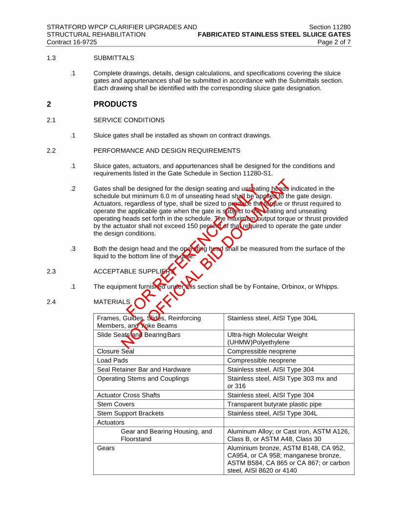
STRATFORD WPCP CLARIFIER UPGRADES AND Section 11280 STRUCTURAL REHABILITATION FABRICATED STAINLESS STEEL SLUICE GATES
Contract 16-9725 Page 2 of 7
1.3 SUBMITTALS
.1 Complete drawings, details, design calculations, and specifications covering the sluice gates and appurtenances shall be submitted in accordance with the Submittals section. Each drawing shall be identified with the corresponding sluice gate designation.
2 PRODUCTS
2.1 SERVICE CONDITIONS
.1 Sluice gates shall be installed as shown on contract drawings.
2.2 PERFORMANCE AND DESIGN REQUIREMENTS
.1 Sluice gates, actuators, and appurtenances shall be designed for the conditions and requirements listed in the Gate Schedule in Section 11280-S1.
.2 Gates shall be designed for the design seating and unseating heads indicated in the schedule but minimum 6.0 m of unseating head shall be applied to the gate design. Actuators, regardless of type, shall be sized to produce the torque or thrust required to operate the applicable gate when the gate is subject to the seating and unseating operating heads set forth in the schedule. The maximum output torque or thrust provided by the actuator shall not exceed 150 percent of that required to operate the gate under the design conditions.
.3 Both the design head and the operating head shall be measured from the surface of the liquid to the bottom line of the gate.
2.3 ACCEPTABLE SUPPLIERS
.1 The equipment furnished under this section shall be by Fontaine, Orbinox, or Whipps.
2.4 MATERIALS
Frames, Guides, Slides, Reinforcing Members, and Yoke Beams
Stainless steel, AISI Type 304L
Slide Seats and Bearing Bars Ultra-high Molecular Weight (UHMW)Polyethylene
Closure Seal Compressible neoprene
Load Pads Compressible neoprene
Seal Retainer Bar and Hardware Stainless steel, AISI Type 304
Operating Stems and Couplings Stainless steel, AISI Type 303 mx and or 316
Actuator Cross Shafts Stainless steel, AISI Type 304
Stem Covers Transparent butyrate plastic pipe
Stem Support Brackets Stainless steel, AISI Type 304L
Actuators
Gear and Bearing Housing, and Floorstand
Aluminum Alloy; or Cast iron, ASTM A126, Class B, or ASTM A48, Class 30
Gears Aluminium bronze, ASTM B148, CA 952, CA954, or CA 958; manganese bronze, ASTM B584, CA 865 or CA 867; or carbon steel, AISI 8620 or 4140
FOR REFERENCE O
NLY
NOT OFFIC
IAL B
ID D
OCUMENT

STRATFORD WPCP CLARIFIER UPGRADES AND Section 11280 STRUCTURAL REHABILITATION FABRICATED STAINLESS STEEL SLUICE GATES
Contract 16-9725 Page 3 of 7
Assembly Fasteners Stainless steel, ASTM F593 and F594, Type 304
Anchor Bolts, Nuts, Washers Stainless steel, as specified and in the Anchor Bolts and Expansion Anchors section
Actuator Baseplates and Supports Stainless steel, AISI Type 304L
Grout As specified in the Grout section
Thread Lubricant John Crane “Thred Gard Nickel” or Crawford “Silver Goop” antiseize compound
2.5 CONSTRUCTION
.1 All stainless steel shall be pickled at the mill in accordance to ASTM A380 before being shipped. After fabrication, surfaces shall be cleaned of all lubricants, grease pencil marks, magic marker, oils, tape, paint, or other organic materials of any type.
.2 All stainless steel surfaces after fabrication shall be given a uniform abrasive grit blast to a profile of 50 to 75 µm [2 to 3 mils], providing a uniform matte finish, using only new blast media which is certified iron-free. Blasting grit shall be black beauty non-metallic 20-40 grit as manufactured by Reed Mineral Company or equal. Blasting shall clean the entire surface and produce an even color, texture, and sheen.
.3 The presence of residual embedded iron shall be determined by using either the 24 hour water test or the ferroxyl test. The method of touch-up, spot pickling, and pickling paste used to remove embedded iron, heat tint, and weld oxides shall comply with ASTM A380, Table A2.1, Part II.
.4 All surfaces shall be adequately protected during fabrication, handling, shipping, and installation to prevent contamination from iron or carbon steel objects, tools, cables, or surfaces.
.5 Frames. Each frame shall be an integral unit of extruded or welded structural shapes having a thickness of not less than 6.4 mm [1/4 inch]. Frames shall be designed for installation on the face of concrete walls. The frame thickness shall not be less than 9.5 mm (3/8 inch) if seating or unseating head is more than 4.0 m.
.6 Guides shall be provided on each side of each frame. Guides shall be sufficiently strong so that no further reinforcing will be required where the guides extend above the operating floor. Guides shall support the entire height of the slide in all positions.
.7 Full-length plastic slide seats or bearing bars shall be provided on both sides of the slide. Seats and bars shall be securely held in the guides by permanent mechanical fasteners evenly spaced along the height of the guides. The guide shall be of such length as to retain and support at least two-thirds (2/3) of the vertical height of the slide in the fully open position.
.8 Slides. Slides shall have a thickness of not less than 6.4 mm [1/4 inch] and shall be provided with welded stiffeners to limit deflection to 1/720 of the gate width under the maximum seating or unseating head specified. Slides shall be adequately reinforced to withstand, without permanent distortion, the maximum thrust which can be transmitted by the operating stem. Each slide shall have a reinforced pocket or internally threaded nut welded to the slide for connection of the stem. The pocket or nut shall be designed to withstand the maximum thrust which can be transmitted by the operating stem. A minimum safety factor of 5 shall be used with regard to tensile, compressive and shear strength of the plate, members, and welds.
FOR REFERENCE O
NLY
NOT OFFIC
IAL B
ID D
OCUMENT

STRATFORD WPCP CLARIFIER UPGRADES AND Section 11280 STRUCTURAL REHABILITATION FABRICATED STAINLESS STEEL SLUICE GATES
Contract 16-9725 Page 4 of 7
.9 Seals. Gates shall be provided with full-length plastic seats or bearing bars on both faces
of the slide. Seats and bars shall be securely attached to the frame with stainless steel retainers and/or stainless steel bolts.
.10 Seals shall be capable of being replaced on site without removing the gate frame from the structure. If a retainer bar is used to fasten the seal to the frame or slide, it shall have adjustable screws keeping the seal in compression. The seal design shall be the standard design of the manufacturer, provided it meets the leakage requirements of the governing standard.
.11 Seating Faces. Seat bearing area shall have a minimum width of 13 mm±. Seating faces shall be secured to either the gate frame or slide, but not both, to ensure that they will remain in place without becoming distorted or loose during the life of the gate. On site replacement of the seating faces must be possible without removing the gate frame from the structure.
.12 Closures. The bottom of each sluice gate frame shall be of the configuration listed in the Gate Schedule. A compressible seal shall be securely attached to the bottom of the slide or to the frame invert. The seal shall be of sufficient length to seal the bottom corners of each slide.
.13 Weir slides may be lowered below the bottom of the opening. A frame member shall be provided at the bottom of the opening to seal the space between the slide and the adjacent concrete. The side guides shall be extended below the bottom of the wall opening. A resilient seal shall be attached to the frame along the invert of the opening and up both sides to seal the slide in all positions.
.14 Each seal shall be provided with a full-length retainer bar which shall compress the seal and prevent leakage between the seal and the frame member. Seals shall be securely attached to the frame and shall permit replacement of the seals without disassembling or removing the gate.
.15 Operating Stems. Operating stems shall conform to the requirements of Section 4.4.11 of AWWA C560 except as modified herein. Stems shall be designed so that the slenderness ratio (L/R) shall be no less than 200. Contact surfaces of threads shall be rolled or machined and polished to a 63 microinch finish, or smoother. Each stem shall be securely attached to the slide. Stems shall be of sufficient size to withstand, without damage or permanent distortion, the tensile and compressive stresses resulting from the application of 1.25 times the output thrust of the actuator in the stalled motor condition. Gates having a width greater than two (2) times their height shall be provided with two (2) lifting mechanisms connected by a tandem shaft whether or not it is indicated on the Contract Drawings. If two stems are required for any size gates as per the Manufacturer’s recommendations, the Contractor shall provide two operation stems at no extra costs. The Manufacturer shall be responsible for the number of operating stems.
.16 Anchor Bolts. The gate manufacturer shall furnish suitable SS304 anchor bolts for each item of equipment supplied herein. Anchor bolts, together with templates or setting drawings, shall be delivered sufficiently early to permit setting the anchor bolts when the structural concrete is placed.
.17 Anchor bolts shall be stainless steel, and alloy type shall be as required. The anchor bolts shall be at least 19 mm diameter. Anchor bolts shall be accurately located and a length approximately 8 times the bolt diameter. Two nuts and a washer shall be furnished with each anchor bolt.
.18 Gates having a width greater than two times their height shall be furnished with two (2) stems connected by gear and dual actuator.
FOR REFERENCE O
NLY
NOT OFFIC
IAL B
ID D
OCUMENT

STRATFORD WPCP CLARIFIER UPGRADES AND Section 11280 STRUCTURAL REHABILITATION FABRICATED STAINLESS STEEL SLUICE GATES
Contract 16-9725 Page 5 of 7
2.6 ACTUATORS
.1 General Requirements. Electric actuators shall conform to the requirements of Section 11290.
.2 Floorstands. Floorstands shall be designed to transfer operating thrusts to the supporting structure or yoke beam. Each floorstand shall be designed to position the crank or handwheel approximately 915 mm above the supporting surface.
.3 Stem Covers. Unless otherwise specified, each manual actuator shall be equipped with a stem cover. Stem covers shall conform to the requirements of Section 3.4 of AWWA C501.
.4 Stem covers shall be constructed of transparent plastic pipe and shall be furnished with a removable end cap, condensation vents, and a clear Mylar position-indicating marking tape. The marking tape shall be adhesive backed and shall be permanently marked and calibrated in feet and inches. The tape shall be field applied to the stem cover after the gate has been installed. The tape shall be positioned so that the height of the slide will be indicated by reference to the top of the stem.
2.7 SHOP PAINTING
.1 All iron and steel surfaces, except machined surfaces and stainless steel surfaces, shall be shop cleaned by blasting in accordance with the coating manufacturer's recommendations and finish painted with an epoxy or epoxy/polyurethane coating system. Actuators and other non-submerged components shall be painted with one coat of epoxy paint having a dry film thickness of at least 125 µm [5 mils] and one topcoat of polyurethane having a dry film thickness at least 50 µm [2 mils]. All components subject to submergence shall be painted with two coats of epoxy paint having a total combined dry film thickness of at least 250 µm [10 mils]. Finish color shall be medium gray, except for handwheels, levers, and other operating devices, which shall be safety red. Field painting of gates, actuators, and appurtenances, other than touchup painting, will not be required. A sufficient quantity of additional coating materials shall be furnished by the gate manufacturer to permit field touchup of damaged coatings.
3 EXECUTION
3.1 INSPECTION
.1 All gates and accessories shall be inspected for damage and cleanliness before being installed. Any material damaged or contaminated in handling on the job shall not be used unless it is repaired and recleaned to the original requirements by the Contractor. Such material shall be segregated from the clean material and shall be inspected and approved by the Engineer or Owner before its use.
3.2 INSTALLATION
.1 Sluice gates and appurtenances shall be handled and installed in accordance with the manufacturer's recommendations and as specified in the Gate Installation section.
.2 Wall thimbles shall be accurately positioned and supported to prevent shifting during placement of surrounding concrete. Square or rectangular thimbles shall be carefully braced both horizontally and vertically to prevent distortion.
.3 Each sluice gate shall be carefully installed and adjusted for proper operation. Care shall be taken to avoid warping the gate frames and to maintain tolerances between seating faces.
FOR REFERENCE O
NLY
NOT OFFIC
IAL B
ID D
OCUMENT

STRATFORD WPCP CLARIFIER UPGRADES AND Section 11280 STRUCTURAL REHABILITATION FABRICATED STAINLESS STEEL SLUICE GATES
Contract 16-9725 Page 6 of 7
.4 Each actuator shall be accurately set and plumbed and shall be in proper alignment with
the gate and stem before the actuator is grouted in place. Operating stems shall be installed in proper alignment and shall not bind in the lift nut or stem guides.
.5 The threaded portion of each plastic stem cover shall be wrapped in at least two layers of Teflon thread tape and immediately before installation of the cover on the actuator.
.6 All bolts shall be tightened and all items requiring lubrication shall be lubricated. Anti seize thread lubricant shall be liberally applied to the threaded portion of stainless steel anchor bolts during installation and tightening of nuts. Excess lubricant shall be thoroughly removed following final tightening.
.7 After installation, each gate shall be operated through at least two complete open close cycles, readjusted and re-operated as necessary, and left in a condition acceptable to the Engineer.
3.3 INSTALLATION CHECK
.1 An experienced, competent, and authorized representative of the gate manufacturer shall visit the site of the Work and inspect, check, adjust if necessary, and approve the equipment installation. In each case, the manufacturer's representative shall be present when the equipment is Field Leakage Tested in accordance with standard industry procedure. The manufacturer's representative shall revisit the jobsite as often as necessary until all trouble is corrected and the equipment installation and operation are satisfactory in the opinion of Engineer.
.2 Each manufacturer's representative shall furnish to Owner, through Engineer, a written report certifying that the equipment has been properly installed and lubricated; is in accurate alignment; is free from any undue stress imposed by connecting piping or anchor bolts; and has been operated under full load conditions and that it operated satisfactorily.
.3 All costs for these services shall be included in the Contract Price.
3.4 FIELD QUALITY CONTROL
.1 Field Leakage Testing. After installation, all gates shall be tested for leakage.
.2 Leakage exceeding the specified limits which is discovered within the correction period stipulated in the General Conditions shall be repaired by and at the expense of the Contractor. This requirement applied whether pressure testing is required or not.
.3 For the maximum seating heads, the leakage shall not exceed 1.25L/min/meter (0.1 gpm per foot) of seating perimeter. For the maximum unseating heads, the leakage shall not exceed 2.5L/min per meter (0.2 gpm per foot) of the seating perimeter.
3.5 TRAINING
.1 In addition to the installation and operation check required by the General Equipment Stipulations and the manufacturer’s field services required by the quality control section, the manufacturer shall furnish the services of a competent and experienced operator of the equipment, who is directly employed by the manufacturer, to instruct the Owner’s operating personnel in the proper operation and maintenance of the equipment. Training shall be provided as specified in Section 01820 – Demonstration and Training.
FOR REFERENCE O
NLY
NOT OFFIC
IAL B
ID D
OCUMENT

STRATFORD WPCP CLARIFIER UPGRADES AND Section 11280 STRUCTURAL REHABILITATION FABRICATED STAINLESS STEEL SLUICE GATES
Contract 16-9725 Page 7 of 7
3.6 WARRANTY
.1 Each unit shall be new and shall carry the full manufacturer’s warranty on parts, service and performance. Warranty shall begin at substantial completion. The warranty shall include replacement of all defective equipment and shall extend two (2) years beyond the date of completion.
.2 Corrective Work. Any location where corrosion is evident shall be considered a failure of the material or the protection system. Before starting work, the manufacturer shall submit to the Engineer for review, an analysis of the cause of the failure and details of the proposed corrective work. The manufacturer shall make repairs acceptable to the Engineer at all points where failures are observed within the Warranty Period.
.3 Inspection. Each unit shall be inspected at the end of the warranty period by representatives of the Owner, the Engineer and the manufacturer to identify any failures that may have occurred. The manufacturer shall establish the date of each inspection and shall notify the Owner at least 30 days in advance. The scheduled inspection shall not relieve the manufacturer from the obligation to perform corrective work whenever needed.
.4 The manufacturer shall prepare and deliver to the Owner an inspection report covering each inspection, indicating the number of type of failures observed, material and part where materials have failed, the percentage of the surface area where corrosion protection system failure has occurred, and the names of the persons making the inspection. Colour photographs illustrating each type of failure shall be included in the report.
END OF SECTION
FOR REFERENCE O
NLY
NOT OFFIC
IAL B
ID D
OCUMENT

FOR REFERENCE O
NLY
NOT OFFIC
IAL B
ID D
OCUMENT

City of Stratford Stratford WPCP Clarifier Upgrades and Structural Rehabilitation Section 11280S1
Gate Schedule
Item Tag NumberGate Size mm
(WxH)Gate Type
Stem
Configuration
Operating Floor EL
(m)
Gate Bottom
Elevation (m)Mounting
Seating
Level (m)
Unseating
Level (m)Location Actuator Type
Drawing No.
for
Locations
Remark
1 IG-131 550x550 Slide Rising 348.657 346.916 Wall 347.700 347.700 Clarifier 1 Feed Pipe Electric P202
2 IG-132 550x550 Slide Rising 348.657 346.916 Wall 347.700 347.700 Clarifier 2 Feed Pipe Electric P202 Normally closed
3 IG-133 550x550 Slide Rising 348.657 346.916 Wall 347.700 347.700 Clarifier 3 Feed Pipe Electric P202
4 IG-134 550x550 Slide Rising 348.657 346.916 Wall 347.700 347.700 Clarifier 4 Feed Pipe Electric P202 Normally closed
Note 1. Gate bottom elevation indicates when the gate is at the completely closed position.
FOR REFERENCE O
NLY
NOT OFFIC
IAL B
ID D
OCUMENT

FOR REFERENCE O
NLY
NOT OFFIC
IAL B
ID D
OCUMENT

STRATFORD WPCP CLARIFIER UPGRADES AND Section 11290 STRUCTURAL REHABILITATION VALVE AND GATE ACTUATORS
Contract 16-9725 Page 1 of 9
1 GENERAL
1.1 SCOPE
.1 This section covers furnishing manual and powered valve and gate actuators and accessories including powered valve and gate actuator retrofits as specified herein.
1.2 GENERAL
.1 Equipment provided under this section shall be fabricated and assembled in full conformity with drawings, specifications, engineering data, instructions, and recommendations of the equipment manufacturer, unless exceptions are noted by Engineer.
.2 Actuators shall be furnished with all necessary parts and accessories indicated on the drawings, specified, or otherwise required for a complete, properly operating installation and shall be the latest standard products of a manufacturer regularly engaged in the production of actuators.
.3 General Equipment Requirements. The General Equipment Requirements shall apply to the equipment furnished under this section.
.4 Governing Standards. Except as modified or supplemented herein, all powered actuators shall conform to applicable requirements of ANSI/AWWA C540, Class 150B.
.1 Except as modified or supplemented herein, all manual and cylinder actuators for butterfly and eccentric plug valves shall conform to the applicable requirements of ANSI/AWWA C504.
.2 Except as modified or supplemented herein, all manual actuators for ball valves shall conform to the applicable requirements of ANSI/AWWA C507.
.3 Except as modified or supplemented herein, all manual actuators for sluice gates shall conform to the applicable requirements of ANSI/AWWA C560.
.5 Power Supply. Power supply to electric actuators will be as indicated on the valve or gate schedule or as indicated on the drawings.
.6 Marking. Each actuator shall be marked with the manufacturer's name, model number, and the country of origin. An identifying serial number shall be stamped on a corrosion-resistant plate attached to the actuator.
.7 Temporary Number Plates. Each actuator shall be factory tagged or marked to identify the actuator and the applicable valve or gate by number or service as indicated in the valve or gate schedule.
1.3 SUBMITTALS
.1 Complete drawings, details, and specifications covering the actuators and their appurtenances shall be submitted in accordance with the submittals section. Submittal drawings shall clearly indicate the country of origin of each actuator and its components.
.2 The drawings shall include separate wiring diagrams for each electrically operated or controlled actuator and the electrical control equipment. Each actuator drawing shall be identified with the respective valve number or name.
FOR REFERENCE O
NLY
NOT OFFIC
IAL B
ID D
OCUMENT

STRATFORD WPCP CLARIFIER UPGRADES AND Section 11290 STRUCTURAL REHABILITATION VALVE AND GATE ACTUATORS
Contract 16-9725 Page 2 of 9
.3 For electric or cylinder actuators, certified copies of reports covering proof of design
testing of the actuators as set forth in Section 5 of ANSI/AWWA C540, together with an affidavit of compliance as indicated in Section 6.3 of ANSI/AWWA C540, shall be submitted to Engineer before the actuators are shipped.
1.4 DELIVERY, STORAGE, AND HANDLING
.1 Shipping shall be in accordance with the shipping section. Handling and storage shall be in accordance with the handling and storage section.
2 PRODUCTS
2.1 PERFORMANCE AND DESIGN REQUIREMENTS
.1 General. Actuators and appurtenances shall be designed for the conditions and requirements as indicated in the respective valve and gate sections.
.2 Liberal factors of safety shall be used throughout the design, especially in the design of parts subject to intermittent or alternating stresses. In general, working stresses shall not exceed one third of the yield point or one fifth of the ultimate strength of each material.
.3 Valve Actuators. Each actuator shall be designed to open or close the valve under all operating conditions. Actuators shall be designed for the maximum pressure differential across the valve and maximum velocities through the valve where indicated in the valve schedule.
.1 Valve actuators shall be provided and adjusted by the valve manufacturer. Actuator mounting arrangements and positions shall facilitate operation and maintenance and shall be determined by the valve manufacturer unless indicated otherwise on the drawings or directed by Engineer.
.2 When valves are to be buried, submerged, or installed in vaults, the actuators and accessories shall be sealed to prevent the entrance of water. The design water depth shall be as indicated in the valve schedule but not less than 6.1 m [20 feet].
.4 Gate Actuators. Actuators shall be sized to produce the torque or thrust required to operate the gate when subject to the seating and unseating operating heads as indicated in the gate schedule.
.5 Both the design head and the operating head shall be measured from the surface of the liquid to the center line of the gate.
.6 Limit Switches. Limit switches shall be provided as indicated in the respective valve and gate schedules.
.1 For manual or cylinder type actuators, each limit switch shall be heavy duty type, with a cast NEMA Type 4 enclosure, a spring return roller lever, and four isolated contacts (two normally open and two normally closed) rated 10 amperes at 120 to 480 volts ac and 5 amperes at 125 volts dc. The switches shall be Allen Bradley "802T" or Square D "9007 Type C".
.2 Limit switches for programmable and standard electric actuators shall be as indicated in their respective paragraphs.
FOR REFERENCE O
NLY
NOT OFFIC
IAL B
ID D
OCUMENT

STRATFORD WPCP CLARIFIER UPGRADES AND Section 11290 STRUCTURAL REHABILITATION VALVE AND GATE ACTUATORS
Contract 16-9725 Page 3 of 9
2.2 MATERIALS
.1 Except as modified or supplemented herein, materials used in the manufacture of actuators shall conform to the requirements of ANSI/AWWA C504 and C540.
2.3 VALVE MANUAL ACTUATORS
.1 General. Manual actuators of the types listed in the valve schedule shall be provided by the valve manufacturer.
.1 Unless otherwise indicated or specified, each geared manual actuator shall be equipped with an operating handwheel.
.2 The direction of rotation of the wheel, wrench nut, or lever to open the valve shall be to the left (counterclockwise). Each valve body or actuator shall have cast thereon the word "Open" and an arrow indicating the direction to open.
.3 The housing of traveling nut type actuators shall be fitted with a removable cover which shall permit inspection and maintenance of the operating mechanism without removing the actuator from the valve. Travel limiting devices shall be provided inside the actuator for the open and closed positions. Travel limiting stop nuts or collars installed on the reach rod of traveling nut type operating mechanisms shall be field adjustable and shall be locked in position by means of a removable roll pin, cotter pin, or other positive locking device. The use of stop nuts or adjustable shaft collars which rely on clamping force or setscrews to prevent rotation of the nut or collar on the reach rod will not be acceptable.
.4 Each actuator shall be designed so that shaft seal leakage cannot enter the actuator housing.
.5 Actuators shall produce the required torque with a maximum pull of 356 N [80 lbs] on the lever, handwheel, or chain. Actuator components shall withstand, without damage, a pull of 890 N [200 lbs] on the handwheel or chainwheel or an input of 407 J [300 foot lbs] on the operating nut.
.2 Handwheels. Handwheel diameters shall be at least 200 mm [8 inches] but not more than 600 mm [24 inches] for 750 mm [30 inch] and smaller valves and not more than 750 mm [30 inches] for 900 mm [36 inch] and larger valves.
.3 Chain wheels Unless otherwise specified in the valve schedule, all valves with center lines more than 2.0 m above the floor shall be provided with chainwheels and operating chains. Each chainwheel operated valve shall be equipped with a chain guide which will permit rapid handling of the operating chain without "gagging" of the wheel and will also permit reasonable side pull on the chain. Suitable extensions shall be provided, if necessary, to prevent interference of the chain with adjacent piping or equipment. Operating chains shall be hot dip galvanized or zinc plated carbon steel and shall be looped to extend to within 1.2 m [4 feet] of the floor below the valve.
.4 Levers. Levers shall be capable of being locked in at least five (5) intermediate positions between fully open and fully closed. In any building or structure containing lever operated valves, at least two operating levers shall be provided for each size and type of lever operated valve.
FOR REFERENCE O
NLY
NOT OFFIC
IAL B
ID D
OCUMENT

STRATFORD WPCP CLARIFIER UPGRADES AND Section 11290 STRUCTURAL REHABILITATION VALVE AND GATE ACTUATORS
Contract 16-9725 Page 4 of 9
.5 Wrench Nuts. Unless otherwise specified in the valve schedule or on the drawings,
wrench nuts shall be provided on all buried valves and on all valves that are to be operated through floor boxes. Unless otherwise directed by Owner, all wrench nuts shall comply with Section 3.15 of AWWA C500. At least two operating keys shall be furnished for operation of the wrench nut operated valves.
.6 Operating Stands. Operating stands shall be provided in the locations indicated on the drawings. Operating stands shall support the handwheel approximately 900 mm [36 inches] above the floor. A sleeve made from standard weight galvanized steel pipe shall be provided for the opening in the floor beneath each operating stand. When stems are 3 m [10 feet] or longer, a suitable thrust bearing shall be provided in each operating stand to carry the weight of the extension stem.
2.4 GATE MANUAL ACTUATORS
.1 General. Manual actuators of the types listed in the gate schedule shall be provided by the gate manufacturer.
.1 All bearings and gears shall be totally enclosed in a weathertight housing having a sufficient number of fittings to permit periodic lubrication of all internal moving components without partial or total disassembly of the mechanism. The pinion shaft of crank operated mechanisms shall be supported by roller bearings or needle bearings.
.2 The direction of rotation of the wheel, crank, or wrench nut to open the gate shall be to the left (counterclockwise).
.3 Actuators for rising stem self contained gates shall be designed for mounting directly on the frame yoke.
.2 Remote Actuators. Remote actuators shall be operated by a frame mounted handwheel and chain drive. An extension shaft suitable for connection to the pinion shaft of the benchstand shall be provided complete with a roller chain, shaft couplings, support bearings, and a roller chain sprocket keyed or bolted to the end of the shaft. A handwheel with bearing housing and sprocket shall be bolted to the side frame approximately 1200 mm [48 inches] above the operating floor. Removable aluminum or stainless steel weathertight covers shall be provided to protect the extension shaft, drive chain, and sprockets. Handwheel and sprocket diameters shall be selected to operate the gate under the maximum specified seating pressure with an effort of not more than 178 N [40 lbs] applied to the rim of the handwheel. Handwheels and sprockets shall be able to withstand a 445 N [100 lb] effort without damage.
.3 Floorstands. Floorstands shall be designed to transfer operating thrusts to the supporting structure. Each floorstand shall be designed to position the crank or the handwheel approximately 900 mm [36 inches] above the frame yoke, supporting surface, or adjacent operating floor or platform.
.4 Stem Covers. Rising stem manual actuators shall be provided with a stem cover as indicated in the gate schedule. Stem covers shall conform to Section 4.4 of ANSI/AWWA C560.
.5 Plastic Covers. Covers shall be constructed of transparent plastic pipe and shall be furnished with an end cap, condensation vents, and a clear mylar position-indicating marking tape. The marking tape shall be adhesive backed and shall be permanently marked and calibrated in meters and millimeters [feet and inches]. The tape shall be applied to the stem cover after the gate has been installed and shall be so positioned that the height of the slide will be indicated by reference to the top of the stem.
FOR REFERENCE O
NLY
NOT OFFIC
IAL B
ID D
OCUMENT

STRATFORD WPCP CLARIFIER UPGRADES AND Section 11290 STRUCTURAL REHABILITATION VALVE AND GATE ACTUATORS
Contract 16-9725 Page 5 of 9
2.5 STANDARD ELECTRIC ACTUATORS
.1 General. Standard electric actuators as listed in the valve and gate schedules shall be provided by the valve or gate manufacturer.
.1 Standard electric actuators for 300 mm [12 inch] and smaller butterfly valves and eccentric plug valves shall be quarter-turn type.
.2 All other standard electric actuators shall be multiturn type and shall be Auma or Rotork.
.3 Standard electric actuators produced by other manufacturers are not acceptable.
.4 Each standard electric actuator shall be furnished complete with a motor, gearing, handwheel, limit switches and torque sensors, lubricants, heating elements, wiring, and terminals. Each actuator shall be constructed as a self contained unit with a cast iron or aluminum alloy housing, of a type as indicated in the valve and gate schedules, and shall be integrally assembled on the applicable valve or gate by the valve or gate manufacturer.
.5 Actuators shall be sized to guarantee valve closure at the specific differential pressure.
.6 Actuators shall be designed to cycle the valve or gate from the fully open to the fully closed position or the reverse in approximately 60 seconds or as indicated in the valve schedule. Sluice gate actuator speed selection shall be selected to achieve 300mm (12 inches) per minute of operating time or as indicated in the gate schedule.
.7 Actuator motors may be mounted horizontally adjacent to or vertically above the reduction gearing. All gearing shall be oil or grease lubricated.
.8 Actuators shall operate at 600V, 3 phase.
.9 Acceptable Suppliers: Rotork or Auma
.2 Motors. Motors shall be totally enclosed, high torque design made expressly for valve actuator service, capable of operating the valve under full differential pressure for two complete strokes or one complete cycle of travel without overheating. Motors shall be designed in accordance with NEMA standards and shall operate successfully at any voltage within 10 percent above or below rated voltage. Motor bearings shall be permanently lubricated. Motors shall be CSA approved and of explosion-proof design.
.3 Power Gearing. Power gearing shall consist of hardened steel spur or helical gears and alloy bronze or hardened steel worm gear, all suitably lubricated, designed for 100 percent overload, and effectively sealed against entrance of foreign matter. Steel gears shall be hardened to at least 350 Brinell. Planetary or cycloidal gearing or aluminum, mild steel, or nonmetallic gears will not be acceptable. Gearing shall be designed to be self locking so that actuation of a torque switch by a torque overload condition will not allow the actuator to restart until the torque overload has been eliminated. If a secondary gear box is required, it shall be designed to withstand the locked rotor torque of the actuator.
.4 Handwheel Mechanism. The handwheel shall not rotate during motor operation. During handwheel operation the motor shall not affect the actuator operation. The actuator shall be responsive to electrical power and control at all times and, when under electrical control, shall instantly disengage the handwheel. The handwheel shall rotate counterclockwise to open the valve. An arrow indicating the opening direction and the word "Open" shall be cast on the handwheel. The force required to operate the
FOR REFERENCE O
NLY
NOT OFFIC
IAL B
ID D
OCUMENT

STRATFORD WPCP CLARIFIER UPGRADES AND Section 11290 STRUCTURAL REHABILITATION VALVE AND GATE ACTUATORS
Contract 16-9725 Page 6 of 9
handwheel shall not exceed 350 N [80 lbs]. The handwheel shall have a padlockable declutch lever.
.5 Torque Sensing. Torque and thrust loads in both closing and opening directions shall be limited by a torque sensing device. Each torque sensing device shall be provided with an adjustment setting indicator. The adjustment shall permit a variation of approximately 40 percent in torque setting. Switches shall have a rating of not less than 6 amperes at 120 volts ac and 0.5 ampere at 115 volts dc.
.6 Limit Switches. Each standard electric actuator shall be designed to be readily field adaptable for four limit switch assemblies. Each switch assembly shall consist of at least three separate limit switches, shall be operated by the driving mechanism, and shall be independently adjustable to trip at any point at and between the fully open and fully closed valve positions. All switches shall have an inductive contact rating of not less than 6 amperes at 120 volts ac, 3 amperes at 240 volts ac, 1.5 amperes at 480 volts ac, and 0.5 ampere at 115 volts dc.
.7 Each quarter turn actuator shall be provided with end of travel limit switches in addition to four (4) SPDT switches, each independently adjustable at any point of valve travel.
.8 Position Transmitter. All valve and gate actuators shall be provided with an electronic type position transmitter. The transmitter output shall be an isolated 4-20 mA DCcapable of driving an external load of up to 500 ohms. Accuracy of the transmitted signal shall be ±2 percent of span. Repeatability and hysteresis shall be within 1 percent. Position shall be displayed on the actuator and also be available remotely through the 4-20 mA signals to SCADA. Position transmitter shall be heavy duty type with a NEMA 4 enclosure rated at 125 VDC. Provide a digital LCD display or glass covered white background mechanical dial position indicator.
.9 Modulating Service. Where in the valve and gate schedule modulating actuators shall be rated for 1200 starts per hour and be equipped with 4-20 mA input and output.
.10 Heating Elements. Space heating elements shall be provided to prevent condensation in the motor and limit switch housing. Heating elements shall be rated 120 volts ac. Heaters shall be continuously energized.
.11 Terminal Facilities. Terminal facilities for connection to motor leads, switches, position transmitter, and heating elements shall be provided in readily accessible terminal compartments. Each terminal compartment shall have at least two openings for external electrical conduits, one sized at least 19 mm [3/4 inch] and the other at least 31 mm [1-1/4 inches]. Each terminal compartment shall be large enough to allow easy routing and termination of fifteen 12 AWG [4 mm2] conductors.
.12 Controller. Each valve shall be furnished with a reversing controller located inside the actuator enclosure and shall have controller devices as indicated in the valve and gate schedules. The controller shall be equipped with:
.1 A motor overload protective device in each phase or solid state motor protection.
.2 A space heater element, rated 120 volts ac, sized to be continuously energized for prevention of condensation within the controller enclosure.
.3 A fused control power circuit taken from one power lead on the load side of the breaker and line side of the reversing starter to ground. If power supply is greater than 120 volts ac, a control power transformer with fused secondary, with volt-ampere capacity suitable for starter control plus continuous service to space
FOR REFERENCE O
NLY
NOT OFFIC
IAL B
ID D
OCUMENT

STRATFORD WPCP CLARIFIER UPGRADES AND Section 11290 STRUCTURAL REHABILITATION VALVE AND GATE ACTUATORS
Contract 16-9725 Page 7 of 9
heater elements in motor housing, limit switch compartment, and controller enclosure.
.4 A terminal block with connectors for all external controls. All leads from the actuator motor and limit switch assembly shall be routed to terminal connections in the controller for external connections to all other control devices.
.5 Auxiliary control contacts as indicated in the electrical schematics.
.6 Reversing controllers shall be both mechanically and electrically interlocked and shall be provided with the necessary direct-operated auxiliary contacts for required interlocking and control.
.7 Valve controllers shall be expressly selected for long life and reliable, low maintenance service under rugged service conditions.
.13 Control Module.
.1 Control Performance. For any operating torque within the specified range of the valve actuator, the valve and actuator shall perform within these specified limits:
.1 Linearity: Linearity of actual valve position as compared to demand signal shall be within ±4 percent of span over the entire operating range.
.2 Repeatability: For any repeated demand signal to the valve actuator, the actual valve position shall be repeated.
.3 Deadband: Deadband of the valve actuator shall be adjustable from 1 to 10 percent of span.
.4 Hysteresis: For any repeated demand signal to the valve actuator, from either an increasing or a decreasing direction, the actual valve position shall be repeated within 1 degree of valve shaft rotation.
.14 Devicenet
.1 Where indicated in the valve schedule, actuators shall be equipped with Devicenet protocol.
.15 Electric Actuator Retrofits
.1 Retrofit actuators shall be standard electric actuators complete with a new gear box and all adaptation and mounting hardware such that the retrofit actuator fits properly onto the existing valve.
2.6 ACTUATOR ACCESSORIES
.1 Extension Stems. Extension stems and stem guides shall be furnished when indicated in the respective valve schedules, indicated on the drawings, or otherwise required for proper valve operation. Extension stems shall be of solid steel and shall be not smaller in diameter than the stem of the actuator shaft. Extension stems shall be connected to the actuator with a single Lovejoy "Type D" universal joint with grease filled protective boot. All stem connections shall be pinned.
.1 At least two stem guides shall be furnished with each extension stem, except for buried valves. Stem guides shall be of cast iron, bronze bushed, and adjustable in two directions. Stem guide spacing shall not exceed 100 times the stem diameter or 3 m [10 feet], whichever is smaller. The top stem guide shall be
FOR REFERENCE O
NLY
NOT OFFIC
IAL B
ID D
OCUMENT

STRATFORD WPCP CLARIFIER UPGRADES AND Section 11290 STRUCTURAL REHABILITATION VALVE AND GATE ACTUATORS
Contract 16-9725 Page 8 of 9
designed to carry the weight of the extension stem. The extension stem shall be provided with a collar pinned to the stem and bearing against the stem thrust guide.
.2 Extension stems for chemical resistant butterfly valves located in drainage sumps shall be the two-piece type with stainless steel stem, PVC housing, wall support, and collar. Unless otherwise indicated on the drawings, the length of the stem extension shall be as necessary to position the valve operator 300 mm [12 inches] above the maximum liquid level in the immediate area.
.3 Extension stems for buried valve actuators shall extend to within 150 mm [6 inches] of the ground surface, shall be centered in the valve box using spacers, and shall be equipped with a wrench nut.
.4 Extension stems for buried valve actuators shall be provided with position indicators as specified in the valve schedules.
.2 Position Indicators. Unless otherwise specified, each valve actuator shall be provided with a position indicator to display the position of the plug or disc relative to the body seat opening.
.1 For quarter turn plug, ball, or cone type valves installed in interior locations, the indicating pointer shall be mounted on the outer end of the valve operating shaft extension and shall operate over an indicating scale on the operating mechanism cover. Where the shaft passes through the cover, a suitable stuffing box or other seal shall be provided to prevent the entrance of water.
.2 Each actuator for butterfly valves, except where located in manholes, buried, or submerged, shall have a valve disc position indicator mounted on the end of the valve shaft. A disc position indicator shall also be provided on each operating stand or the actuator mounted thereon.
2.7 PORTABLE VALVE OPERATOR
.1 Provide two (2) portable valve operators with electric drive gun.
.2 The LCD display indicates information on direction of drive and the current torque output; 100 Nm (74 lbf ft) to 100,100 Nm (73,700 lbf ft).
.3 Hose length supplied: 5 metres.
.4 CE and EMC certified.
.5 Acceptable Suppliers: Smith Flow Control Ltd., or Engineer approved equal.
2.8 SHOP PAINTING
.1 All ferrous metal surfaces, except bearing and finished surfaces and stainless steel components of valve actuators and accessories, shall be shop painted for corrosion protection. The valve manufacturer's standard coating will be acceptable, provided it is functionally equivalent to the specified coating and is compatible with the specified field painting.
.2 The following surfaces shall be painted:
.1 Polished or Machined Surfaces: Rust Preventive compound.
FOR REFERENCE O
NLY
NOT OFFIC
IAL B
ID D
OCUMENT

STRATFORD WPCP CLARIFIER UPGRADES AND Section 11290 STRUCTURAL REHABILITATION VALVE AND GATE ACTUATORS
Contract 16-9725 Page 9 of 9
.2 Other Surfaces: Epoxy enamel.
.3 Actuators and Accessories: Universal primer.
3 EXECUTION
3.1 INSTALLATION
.1 Actuators will be installed on the valves in accordance with Section 11200 and gates in accordance with Section 11280.
3.2 POWERED VALVE AND GATE ACTUATOR RETROFITS
.1 The actuator supplier shall confirm at the site that the actuator will fit onto the existing valve. The actuator supplier shall supply all necessary adaptation and mounting hardware for that purpose.
.2 The actuator supplier shall size the actuator according to the governing standards stated in 1.2.4 based on valve size, material, stem diameter and line pressure. Verification of this information will be performed by a site visit.
.3 The actuator supplier shall provide startup and commissioning services to the valves with actuator retrofits and provide a warranty for a minimum period of two (2) years from the date of completion.
END OF SECTION
FOR REFERENCE O
NLY
NOT OFFIC
IAL B
ID D
OCUMENT

FOR REFERENCE O
NLY
NOT OFFIC
IAL B
ID D
OCUMENT

STRATFORD WPCP CLARIFIER UPGRADES AND Section 11450 STRUCTURAL REHABILIATION CLARIFIER MECHANISM - CIRCULAR
Contract 16-9725 Page 1 of 16
1 GENERAL
1.1 INTENT OF SECTION
.1 This section covers the supply, delivery, supervision of the installation and commissioning of mechanisms for two (2) clarifiers out of four (4) primary clarifiers as shown on the drawings. Mechanism for Primary Clarifiers 2 and 4 are being carried as provisional items.
.2 Two (2) clarifiers have since had their mechanisms removed and are currently used to equalize peak wet weather flow ahead of secondary treatment.
1.2 RELATED SECTIONS
.1 DIVISION 1 – GENERAL REQUIREMENTS
.2 DIVISION 3 – CONCRETE
.3 Section 05500 – Metal Fabrications
.4 Section 11010 – General Equipment Requirements
.5 Section 11090 – Identification of Equipment, Piping and Valves
.6 DIVISION 13 – INSTRUMENTATION, CONTROL AND SCADA
.7 DIVISION 15 – MECHANICAL
.8 DIVISION 16 – ELECTRICAL
1.3 GENERAL
.1 Equipment furnished under this section shall be fabricated, assembled, erected, and placed in proper operating condition in full conformity with drawings, specifications, engineering date, instructions and recommendations of the screens manufacturer, unless exceptions are as noted by the Engineer.
.2 Coordination. The Clarifier Mechanism shall be installed in the existing primary clarifiers No.1 and No.3 as shown on the drawings. The Clarifier supplier shall verify that each component of the system is compatible with all other components of the system; and that all devices for a properly functioning system have been provided. The Contractor is responsible for overall coordination of the equipment package to ensure its compatibility with other equipment. The Contractor shall decommission the existing mechanism completely and dispose of them off-site.
.3 General Equipment Stipulations. The General Equipment Stipulations shall apply to all equipment furnished under this section.
.4 Equipment Schedule. Manufacturer’s field services, operation and maintenance manuals, and certificates of compliance shall be provided for all items of equipment furnished under this Contract.
.5 Specific requirements for manufacturer’s field services are covered in the quality control section. Specific requirements for operation and maintenance manuals and certificates of compliance are covered in the submittals section.
FOR REFERENCE O
NLY
NOT OFFIC
IAL B
ID D
OCUMENT

STRATFORD WPCP CLARIFIER UPGRADES AND Section 11450 STRUCTURAL REHABILIATION CLARIFIER MECHANISM - CIRCULAR
Contract 16-9725 Page 2 of 16
.6 Power Supply. Power supply to equipment will be 575 volts, 60 Hz, 3 phase.
1.4 SUBMITTALS
.1 In accordance with Section 01330 – Submittal Procedures.
.2 Complete fabrication, assembly, tank, installation drawings, proposed layout, motor and anchor bolt base plans, together with detailed specifications and data covering materials, parts, devices, and accessories forming a part of the equipment furnished, shall be submitted in accordance with a the submittals section.
.3 Complete assembly drawing of the collector components giving:
.1 Type of material used for each component
.2 Dimension, thicknesses and weights of each component
.4 Spare parts shall be suitably packaged in accordance with the General Equipment Stipulations with labels indicating the contents of each package. Spare parts shall be delivered to the Owner as directed. Spare parts shall be shipped in separate packages from the installed components. If any of the spare parts or supplies are used during the testing process, they must be replaced by the Manufacturer at no cost to the Owner.
.5 The clarifier equipment manufacturer shall furnish as a minimum the following design and description information to establish compliance with these specifications:
.1 Certified general arrangement and tank dimensional drawings.
.2 Certificate of design stamped by a Registered Professional Engineer stating that the equipment to be provided for this project meets or exceeds all design requirements of these specifications. The certificate shall state the respective loads and design criteria.
.3 Drive mechanism rating calculations, stamped by a Registered Professional Engineer, verifying the compliance of the drive gears and bearings with the specified continuous torque rating and bearing life rating.
.4 Motor data and catalog information. Electrical drawings as applicable to the supply of the clarifier equipment manufacturer.
.5 Catalog cut sheets for purchased sub-components.
.6 The submittal shall include data from a minimum of five (5) successfully operating installations that verify the experience of the manufacturer.
1.5 APPLICABLE CODES AND STANDARDS
.1 The following minimum applicable codes, standards and regulations must be adhered to in the design, installation and services provided by the Vendor. In the case of conflicting information among these codes, it is the Vendor’s responsibility to inform and obtain written approval from the Purchaser of any exceptions hereby taken.
.2 Requirements from the following organizations shall be considered as a minimum:
.1 American Society of Testing Materials (ASTM):
.1 A36 Structural Steel Specifications
FOR REFERENCE O
NLY
NOT OFFIC
IAL B
ID D
OCUMENT

STRATFORD WPCP CLARIFIER UPGRADES AND Section 11450 STRUCTURAL REHABILIATION CLARIFIER MECHANISM - CIRCULAR
Contract 16-9725 Page 3 of 16
.2 A992 Structural Steel Specifications
.3 304 Bolt Specifications
.4 A123 Hot-Dip Galvanized Coatings
.5 A153 Hot-Dip Galvanized Bolts
.6 A48 Cast Iron Specifications
.7 A536 Ductile Iron Specifications
.8 A283C Steel Plate Specifications
.9 A276 Stainless Steel Bars and Shapes
.10 A167 Stainless and Heat-Resisting Chromium-Nickel Steel Plate, Sheet, and Strip
.2 American Iron and Steel Institute (AISI), Heat Treated Steel Specifications
.3 American Gear Manufacturers' Association (AGMA), Gear Ratings
.4 American Welding Society (AWS), Current Standards
.5 Anti-friction Bearing Manufacturers' Association (AFBMA), Bearing Life Specifications
.6 National Electrical Manufacturer's Association (NEMA), Motor Design Standards and Standards for Control Enclosures
1.6 QUALIFICATIONS
.1 Manufacturer's Experience
.1 It is the intention of this specification to cover minimum acceptable quality for a complete installation with the exception of the motor controls, electrical work and piping requirements. The electrical/mechanism from each manufacturer shall be reviewed by the Engineer if those are equal or equivalent when those are different from them specified herein,
.2 The equipment Manufacturer shall have not less than five (5) successful year experience in the design, construction and operation of the type specified at ten (10) different plants.
.3 The Engineer may require evidence, in the form of operating records, from these plants to substantiate any claims concerning the ability of the equipment to perform as required.
2 PRODUCTS
2.1 SERVICE CONDITIONS
.1 Primary Clarifier Mechanisms shall be used to remove readily settable solids and floating material and reduce the total suspended solids content in the next process.
FOR REFERENCE O
NLY
NOT OFFIC
IAL B
ID D
OCUMENT

STRATFORD WPCP CLARIFIER UPGRADES AND Section 11450 STRUCTURAL REHABILIATION CLARIFIER MECHANISM - CIRCULAR
Contract 16-9725 Page 4 of 16
2.2 PERFORMANCE AND DESIGN REQUIREMENTS
.1 The clarifier mechanism shall be of the center drive type, supported on a stationary influent column, with the flow entering at the bottom of the influent column and flowing upward into the energy dissipating inlet. The flow shall then proceed into the feedwell through gates near the water level for further energy dissipation and settling. The clarifier shall be designed to remove settled sludge from the bottom of the tank and floating scum from around the periphery of the tank.
.2 Design Criteria and Requirements
.1 Average Daily Flow – 30,660 m3/d
.2 Total Peak Process Capacity – 36,503 m3/d
.3 Total Hydraulic Peak Flow – 38,880 m3/d
.4 Internal Diameter including Launder – 26.37 m (86’ 6”)
.5 Actual Internal Diameter except Launder – 24.38 m (80’)
.6 Number of Units to be replaced – 2
.7 Side Water Depth – 2.9 m
.8 Tank Freeboard – 1.3 m
.9 Floor Slope – 1:12
.10 Rotating Speed – 0.04 RPM
.11 Motor Horsepower – Minimum 3/4 hp
.12 Depth and contour as per contract drawings
.13 Hydraulic shall be designed to handle per basin
Parameter Value
Average Flow per basin 15,330 m3/day
Peak Process Capacity per basin 18,250 m3/day
Peak Hydraulic Capacity per basin 19,440 m3/day
Surface Area per basin 466.8 m2
2.3 COMPONENT CONSTRUCTION
.1 General Description
.1 The essential parts of all the equipment are to be made by Equipment Suppliers who have had not less than five (5) years of experience in the design, construction and operation of such equipment for the intended use in wastewater facilities. These specifications direct attention to certain features, but do not purport to cover all details entering into the design of the equipment.
FOR REFERENCE O
NLY
NOT OFFIC
IAL B
ID D
OCUMENT

STRATFORD WPCP CLARIFIER UPGRADES AND Section 11450 STRUCTURAL REHABILIATION CLARIFIER MECHANISM - CIRCULAR
Contract 16-9725 Page 5 of 16
.2 The clarifier mechanism shall be of the center drive type, supported on a
stationary influent column, with the flow entering at the bottom of the influent column and flowing upward into the energy dissipating inlet.
.3 The flow shall then proceed into the feedwell through gates near the water level for further energy dissipation and settling.
.4 The clarifier shall be designed to remove settled sludge from the bottom of the tank and floating scum from around the periphery of the tank. The clarifier shall perform the following integrated functions:
.1 Dissipate energy and control localized currents.
.2 Separate solids form the clear liquid.
.3 Evenly withdraw the clear liquid.
.4 Transport and thicken settled sludge.
.5 Remove scum from the clarifier surface.
.5 Materials
.1 All structural steel shall conform to AISC – Steel Construction Manual latest edition. All steel plates shall conform to ASTM A36. All structural steel shape series of M, MT, S, ST, C, MC, L shall conform to ASTM A36. Structural steel shapes W, WT, HP shall conform to ASTM A992/A572.
.2 All pipe shall be ASTM A53, Grade B. All square and rectangular tubing shall be ASTM A500, Grade B, unless otherwise noted. Steel members in contact with liquids, either continuously or intermittently, shall have a minimum thickness of 1/4 inch unless otherwise noted. All aluminum shall be type 5052, 6061, 6063, or 2014 alloy unless noted. All stainless steel shall be type 304/304L unless noted.
.3 Comply with ASTM A276 Stainless Steel Bars and Shapes and A167 Stainless and Heat-Resisting Chromium-Nickel Steel Plate, Sheet, and Strip to use stainless steel 304.
.6 Fabrication
.1 Shop fabrication and welding of structural members shall be in accordance with the latest edition of the "Structural Welding Code", AWS D1.1, (AWS D1.2-Aluminum, AWS D1.6-Stainless Steel), of the American Welding Society.
.2 All welded connections shall develop the full strength of the connected elements and all joined or lapped surfaces shall be completely seal welded with a minimum 3/16" fillet weld. Intermittent welding shall not be allowed, except on non-ferrous metals.
.7 Edge Grinding
.1 Sharp projections of cut or sheared edges of ferrous metals shall be ground to a radius by multiple passes of a power grinder as required to ensure satisfactory coating adhesion.
FOR REFERENCE O
NLY
NOT OFFIC
IAL B
ID D
OCUMENT

STRATFORD WPCP CLARIFIER UPGRADES AND Section 11450 STRUCTURAL REHABILIATION CLARIFIER MECHANISM - CIRCULAR
Contract 16-9725 Page 6 of 16
.8 Shop Surface Preparation/Coating
.1 All iron and steel surfaces, except the drive unit, shall be field cleaned and painted by the contractor to ensure paint compatibility and assign unit responsibility for the coating system. The drive unit shall be coated with the supplier’s standard enamel paint system.
.9 Structural Design
.1 All steel design shall be in accordance with the AISC Manual of Steel Construction, latest edition and the International Building Code (IBC), latest edition.
.2 Drive Unit
.1 Design Parameters
.1 The drive unit shall be designed and manufactured by the clarifier equipment supplier to ensure unit responsibility. The drive unit shall be designed for the torque values previously listed. It shall turn the mechanism at the design collector tip speed. The drive shall be designed for the total rotating mechanism loads with a minimum L-10 life of 20 years or 175,000 hours.
.2 The drive unit shall be capable of producing and withstanding the previously listed momentary peak torque while starting. The drive main gear shall be designed to a minimum AGMA 5 rating when rated in accordance with the latest AGMA standard. Gear teeth shall be designed for proper load distribution and sharing. Stub tooth design and surface hardening of the main gear shall not be allowed.
.3 The main bearing shall be capable of withstanding the listed overturning moment without the aid of any underwater guides or bearings to ensure correct tooth contact for AGMA rating of the main gear.
.4 All spur (and intermediate) gearing shall be designed to the latest AGMA spur gear standard for strength and surface durability, based on a life of 175,000 hours.
.5 The design running torque rating of the drive gearing shall be based on the smaller of the strength and durability values determined from the above AGMA standards. To ensure safety and ease of maintenance, all components of the drive shall be direct coupled.
.6 Any and all welding on the drive unit shall be done using E70XX weld rod or by AWS certified welders.
.2 Physical Characteristics
.1 The drive unit shall consist of a solid or split internal main spur gear, bearing turntable, pinion, secondary speed reducer, support base, and drive unit bearing. The drive shall be mounted on the center column and support the entire rotating load of the mechanism.
.2 The main internal gear shall be forged of alloy hardened steel or ASTM A536 ductile iron. The pinion shall be heat treated alloy steel. All speed reducers shall be fully enclosed and running in grease or oil. Support
FOR REFERENCE O
NLY
NOT OFFIC
IAL B
ID D
OCUMENT

STRATFORD WPCP CLARIFIER UPGRADES AND Section 11450 STRUCTURAL REHABILIATION CLARIFIER MECHANISM - CIRCULAR
Contract 16-9725 Page 7 of 16
base for the drive shall be of cast iron to assure rigidity. Lubricant and dust shields shall be provided.
.3 The drive bearing shall include a forged steel precision gear/bearing set, with fully contoured raceways hardened to a minimum 58-60 Rc and protected by a neoprene seal.
.4 The main gear to pinion gear mesh shall be oil lubricated. Lubrication fittings shall be readily accessible. Condensate drains shall be provided in the main gear housing.
.3 Overload Protection
.1 An overload device shall be provided in a stainless steel, weatherproof enclosure. The device shall be actuated by torque generated from the main drive, which shall operate two independently adjustable switches (the alarm switch at 100 percent of design running torque and the motor cutout switch at 120 percent of design running torque).
.2 These two switches shall be factory adjusted to accurately calibrate the alarm torque value and the overload position.
.3 A visual torque indicator shall be provided and oriented so that it may be read from the walkway. It shall be calibrated from 0 to 160 percent of design running torque.
.4 The respective switches in the overload control device shall be factory calibrated and set to the following settings:
1. Alarm - 40% of scale.
2. Motor cutout - 85% of scale.
3. Back-up motor cutout or slip clutch - 100% of scale.
.4 Turntable
.1 The turntable base shall have an annular bearing raceway upon which the rotating assembly rests. It shall have a maximum allowable deflection in accordance with the bearing specifications. The allowable modulus of elasticity shall be a minimum of 29 x 106 psi.
.2 The center cage shall be fastened to and supported from the gear casing. Ball bearings shall be of high carbon chrome alloy 52100 steel running in fully contoured races, as part of a precision gear/bearing set or replaceable four strip liner strips fitted into the main gear and turnbable base. The balls shall be grease lubricated and protected by elastomer seals.
.5 Speed Reducing Unit
.1 The speed reducing unit shall consist of worm, cycloidal, helical, or planetary speed reducers connected to a motor directly or by using a chain and sprockets enclosed in a galvanized steel guard.
.2 The main ring gear of cycloidal drives shall be made of high carbon chromium bearing steel and be fixed to the drive casing. An eccentric
FOR REFERENCE O
NLY
NOT OFFIC
IAL B
ID D
OCUMENT
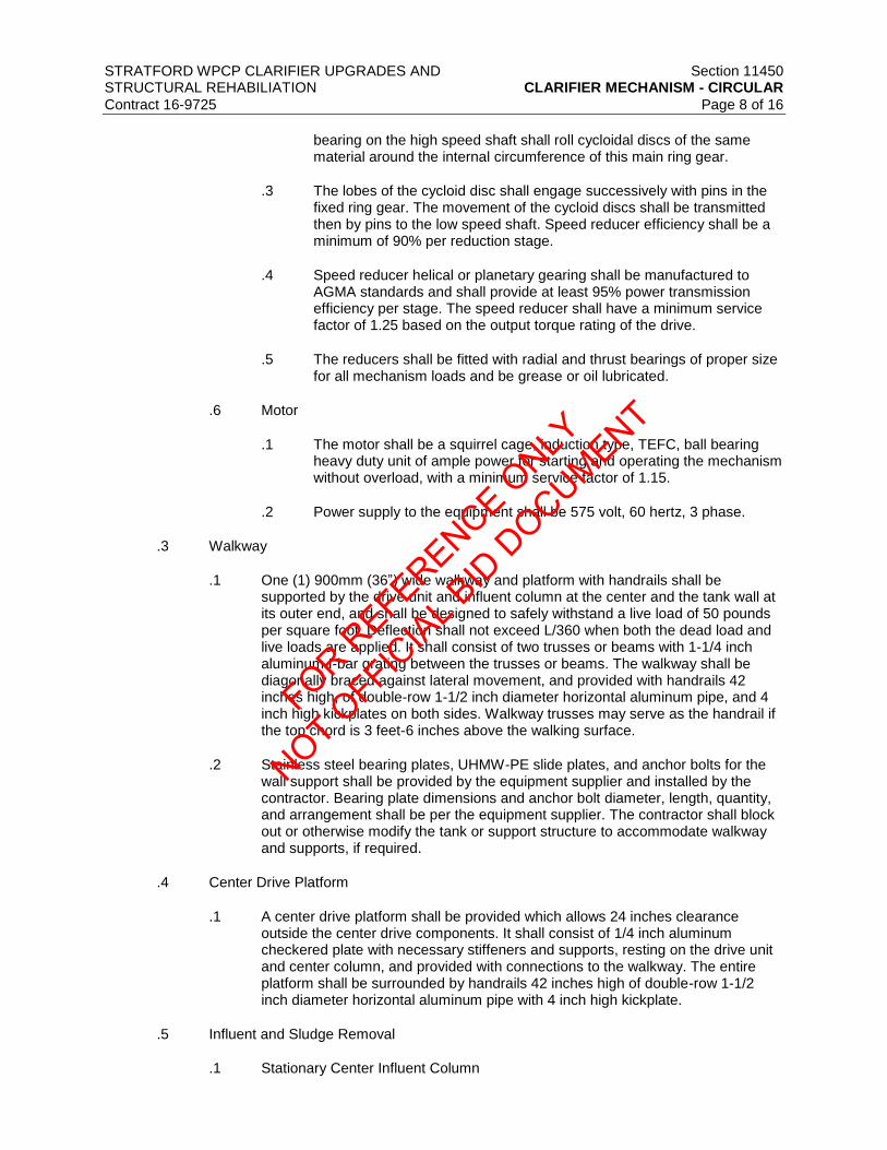
STRATFORD WPCP CLARIFIER UPGRADES AND Section 11450 STRUCTURAL REHABILIATION CLARIFIER MECHANISM - CIRCULAR
Contract 16-9725 Page 8 of 16
bearing on the high speed shaft shall roll cycloidal discs of the same material around the internal circumference of this main ring gear.
.3 The lobes of the cycloid disc shall engage successively with pins in the fixed ring gear. The movement of the cycloid discs shall be transmitted then by pins to the low speed shaft. Speed reducer efficiency shall be a minimum of 90% per reduction stage.
.4 Speed reducer helical or planetary gearing shall be manufactured to AGMA standards and shall provide at least 95% power transmission efficiency per stage. The speed reducer shall have a minimum service factor of 1.25 based on the output torque rating of the drive.
.5 The reducers shall be fitted with radial and thrust bearings of proper size for all mechanism loads and be grease or oil lubricated.
.6 Motor
.1 The motor shall be a squirrel cage, induction type, TEFC, ball bearing heavy duty unit of ample power for starting and operating the mechanism without overload, with a minimum service factor of 1.15.
.2 Power supply to the equipment shall be 575 volt, 60 hertz, 3 phase.
.3 Walkway
.1 One (1) 900mm (36”) wide walkway and platform with handrails shall be supported by the drive unit and influent column at the center and the tank wall at its outer end, and shall be designed to safely withstand a live load of 50 pounds per square foot. Deflection shall not exceed L/360 when both the dead load and live loads are applied. It shall consist of two trusses or beams with 1-1/4 inch aluminum I-bar grating between the trusses or beams. The walkway shall be diagonally braced against lateral movement, and provided with handrails 42 inches high, of double-row 1-1/2 inch diameter horizontal aluminum pipe, and 4 inch high kickplates on both sides. Walkway trusses may serve as the handrail if the top chord is 3 feet-6 inches above the walking surface.
.2 Stainless steel bearing plates, UHMW-PE slide plates, and anchor bolts for the wall support shall be provided by the equipment supplier and installed by the contractor. Bearing plate dimensions and anchor bolt diameter, length, quantity, and arrangement shall be per the equipment supplier. The contractor shall block out or otherwise modify the tank or support structure to accommodate walkway and supports, if required.
.4 Center Drive Platform
.1 A center drive platform shall be provided which allows 24 inches clearance outside the center drive components. It shall consist of 1/4 inch aluminum checkered plate with necessary stiffeners and supports, resting on the drive unit and center column, and provided with connections to the walkway. The entire platform shall be surrounded by handrails 42 inches high of double-row 1-1/2 inch diameter horizontal aluminum pipe with 4 inch high kickplate.
.5 Influent and Sludge Removal
.1 Stationary Center Influent Column
FOR REFERENCE O
NLY
NOT OFFIC
IAL B
ID D
OCUMENT

STRATFORD WPCP CLARIFIER UPGRADES AND Section 11450 STRUCTURAL REHABILIATION CLARIFIER MECHANISM - CIRCULAR
Contract 16-9725 Page 9 of 16
.1 A stationary cylindrical stainless steel 304 influent column of 6 mm
minimum wall thickness shall be provided. One end shall have a support flange for bolting to the tank floor over the influent line, with a similar flange at the top for supporting the drive unit and walkway. The structure and anchor bolts shall provide adequate support for the entire mechanism dead load plus live loads and torque with an adequate factor of safety to eliminate excessive deflection or vibration. Suitable openings shall be provided in the upper portion of the column to allow unrestricted passage of the flow into the energy dissipating inlet.
.2 Prior to the center column being grouted in place, the drive unit shall be installed, positioned, and leveled.
.2 Feedwell
.1 The flocculating feedwell shall diffuse the liquid into the tank without disturbance or formation of velocity currents. Baffled openings shall be provided near the water surface to allow scum to exit the feedwell.
.2 The supports for the feedwell shall be located either above the liquid extending from the cage or bridge, or on the rake arms. Submerged supports from the rake arms shall be designed so as to minimize horizontal flow disruption.
.3 No feedwell support or feedwell spliced connection shall be contained within the annular space formed between the feedwell and EDI. The depth of the feedwell shall be such as to provide proper detention time and an exit velocity at maximum flow that will not scour the settled sludge. The diameter, depth, detention time, and exit velocities shall match the process application calculations as evidenced by the required successful operating installations.
.4 The feedwell shall be made of not less than 6 mm thick stainless steel plate with necessary stiffening angles.
.3 Center Cage (Pier)
.1 The center cage shall be of stainless steel 304 box truss construction. It shall be provided with connections for the two sludge rake arms and feedwell supports if required. The cage top shall be bolted to the main gear which shall rotate the cage with the attached arms and feedwell.
.2 The cage and each arm shall be designed to withstand 150 percent of the design running torque of the drive without over stressing the members. Loading to develop the torque shall be considered as uniform loads applied to each arm individually.
.3 It shall be of an all-welded construction made up of structural stainless steel 304 members having a minimum thickness of 6 mm.
.4 Sludge Rake Arms
.1 The mechanism shall include two long sludge rake arms of stainless steel 304 truss construction with spiral-shaped steel scraper blades and adjustable stainless steel squeegees. Squeegees shall be fastened to the rake blades with stainless steel fasteners.
FOR REFERENCE O
NLY
NOT OFFIC
IAL B
ID D
OCUMENT

STRATFORD WPCP CLARIFIER UPGRADES AND Section 11450 STRUCTURAL REHABILIATION CLARIFIER MECHANISM - CIRCULAR
Contract 16-9725 Page 10 of 16
.2 Scraper blades shall be designed for sufficient sludge transport capacity
to handle the design solids loading rate, with the depth of the blade varying from a minimum at the tank periphery to a maximum at the tank center.
.3 Blades shall properly convey settled sludge to the sludge withdrawal point. Blades which move sludge away from the center column to the withdrawal point ring shall also be provided.
.4 The arms shall be adjustable at the cage to assure an even grout thickness over the tank bottom.
.5 The rake speed shall be sufficient to transport the necessary volume of sludge to the sludge outlet, but shall not re-suspend settled sludge.
.6 Scum Removal
.1 General
.1 The clarifier manufacturer shall furnish two (2) skimming devices as part of each clarifier mechanism.
.2 Each skimming mechanism shall be arranged to sweep the surface of the sedimentation compartment, automatically removing scum and floating material to a scum box at the periphery of the tank.
.2 Skimmer Construction
.1 The rotating scum skimmer shall include a horizontal stainless steel 304 plate skimmer blade supported by vertical steel members extending up from the rake arms. The blade shall extend from a point 6 inches away from the influent feedwell to the hinged scum skimmer assembly at the tank periphery.
.3 Scum Skimmer Assembly
.1 A hinged scum skimmer assembly shall be mounted on the outer end of the skimmer blade. The hinged scum skimmer assembly shall be designed to form a pocket for trapping the scum.
.2 The hinged arrangement shall insure continual contact and proper alignment between wiper blade, scum baffle, and ramp as the blade travels up the scum box ramp. The wiper blade shall have a wearing strip on its outer end which contacts the scum baffle and a neoprene strip on its lower and inner edge.
.3 The neoprene wipers shall be a minimum 1/4 inch thickness. The scum is trapped as the wiper blade meets the ramp and is raised up the ramp to be deposited into the scum trough for disposal.
.4 Scum Box
.1 The scum box shall be of the size specified, supported from the tank wall and connected to the scum withdrawal piping. It shall be made of ¼ inch thick welded stainless steel 304 plate.
FOR REFERENCE O
NLY
NOT OFFIC
IAL B
ID D
OCUMENT
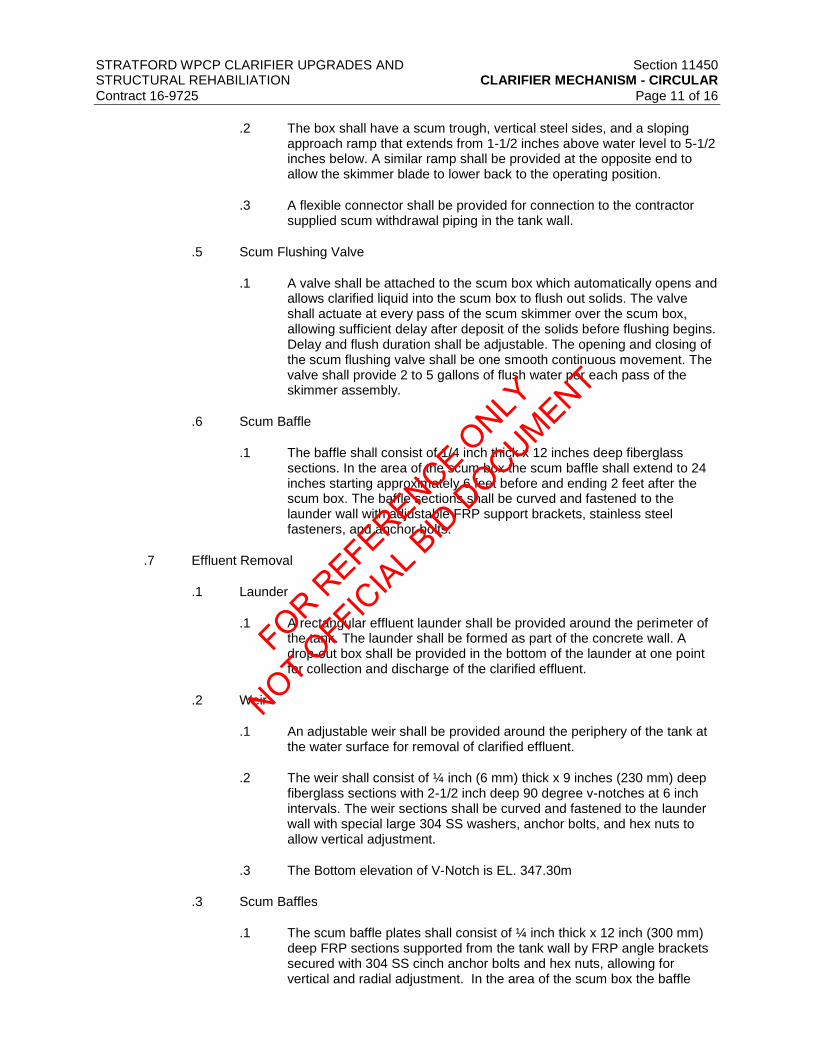
STRATFORD WPCP CLARIFIER UPGRADES AND Section 11450 STRUCTURAL REHABILIATION CLARIFIER MECHANISM - CIRCULAR
Contract 16-9725 Page 11 of 16
.2 The box shall have a scum trough, vertical steel sides, and a sloping
approach ramp that extends from 1-1/2 inches above water level to 5-1/2 inches below. A similar ramp shall be provided at the opposite end to allow the skimmer blade to lower back to the operating position.
.3 A flexible connector shall be provided for connection to the contractor supplied scum withdrawal piping in the tank wall.
.5 Scum Flushing Valve
.1 A valve shall be attached to the scum box which automatically opens and allows clarified liquid into the scum box to flush out solids. The valve shall actuate at every pass of the scum skimmer over the scum box, allowing sufficient delay after deposit of the solids before flushing begins. Delay and flush duration shall be adjustable. The opening and closing of the scum flushing valve shall be one smooth continuous movement. The valve shall provide 2 to 5 gallons of flush water per each pass of the skimmer assembly.
.6 Scum Baffle
.1 The baffle shall consist of 1/4 inch thick x 12 inches deep fiberglass sections. In the area of the scum box the scum baffle shall extend to 24 inches starting approximately 6 feet before and ending 2 feet after the scum box. The baffle sections shall be curved and fastened to the launder wall with adjustable FRP support brackets, stainless steel fasteners, and anchor bolts.
.7 Effluent Removal
.1 Launder
.1 A rectangular effluent launder shall be provided around the perimeter of the tank. The launder shall be formed as part of the concrete wall. A drop-out box shall be provided in the bottom of the launder at one point for collection and discharge of the clarified effluent.
.2 Weir
.1 An adjustable weir shall be provided around the periphery of the tank at the water surface for removal of clarified effluent.
.2 The weir shall consist of ¼ inch (6 mm) thick x 9 inches (230 mm) deep fiberglass sections with 2-1/2 inch deep 90 degree v-notches at 6 inch intervals. The weir sections shall be curved and fastened to the launder wall with special large 304 SS washers, anchor bolts, and hex nuts to allow vertical adjustment.
.3 The Bottom elevation of V-Notch is EL. 347.30m
.3 Scum Baffles
.1 The scum baffle plates shall consist of ¼ inch thick x 12 inch (300 mm) deep FRP sections supported from the tank wall by FRP angle brackets secured with 304 SS cinch anchor bolts and hex nuts, allowing for vertical and radial adjustment. In the area of the scum box the baffle
FOR REFERENCE O
NLY
NOT OFFIC
IAL B
ID D
OCUMENT

STRATFORD WPCP CLARIFIER UPGRADES AND Section 11450 STRUCTURAL REHABILIATION CLARIFIER MECHANISM - CIRCULAR
Contract 16-9725 Page 12 of 16
shall extend 24 inches (600 mm) deep starting approximately 6 feet (1.8 m) preceding and ending 6 feet following the scum box.
.8 ENERGY DISSIPATING INLET
.1 ENERGY DISSIPATING INLET (EDI) is not required for this clarifier mechnism.
.9 SPARE PARTS
.1 As a minimum, provide the following spare parts, per clarifier:
.1 One (1) sight glass for each main drive housing containing oil.
.2 One (1) set of neoprene skimmer wipers.
2.4 ACCEPTABLE MANUFACTURES
.1 Westech
.2 Ovivo
.3 Evoqua Water Technologies
.4 Veolia Water Technologies
2.5 MANUFACTURE AND FABRICATION
.1 Welding. All structural butt welds shall be of full penetration. Equipment shall be free of any damages such as indentations and cracks. All welded joints shall be of similar chemistry, corrosion resistance and physical properties to the base metal being welded.
.2 Edge Grinding. Sharp projections of cut or sheared edges of metals, which will be submerged in operation, shall be ground to a radius.
2.6 MECHANISM MATERIALS
.1 Unless otherwise specified or permitted, the materials used in the fabrication of the equipment furnished under this section shall conform to the following
Bridge Stainless Steel 304
Structural Members Stainless Steel 304
Gear Housing Gray Cast Iron, ASTM A48
Walkway Aluminum Grating
Handrail Sch. 40 Aluminum Pipe
Effluent Weirs Fiberglass or Stainless Steel 304
Scum Baffles Fiberglass or Stainless Steel 304
Scum Box Stainless Steel 304
Hardware 316 SS
Pipe Stainless Steel 304
2.7 CONTROL PANELS
.1 Refer to Electrical Drawings for control panel schematic. Contractor shall ensure that requirements on E002 are met.
FOR REFERENCE O
NLY
NOT OFFIC
IAL B
ID D
OCUMENT

STRATFORD WPCP CLARIFIER UPGRADES AND Section 11450 STRUCTURAL REHABILIATION CLARIFIER MECHANISM - CIRCULAR
Contract 16-9725 Page 13 of 16
.2 Contractor shall provide a control panel schematic to the Engineer for review prior to
purchase of equipment. Control panel shop drawing/schematic must confirm to E002, detail 2 with motor starter integral to control panel.
.3 The Clarifier manufacturer shall be provide a NEMA 4X, 304 stainless steel control panel to control and protect the Clarifier mechanism. The control panel shall be wired to accept a 575 V power feed, a control power transformer shall be provided to power all internal controls.
.4 The control panel shall be built in a UL508A/698 certified panel shop.
.5 The control panel shall be provided with the following devices mounted on the exterior of the enclosure.
.1 Top mounted amber strobing alarm light, Federal Signal LP3P.
.2 Top mounted alarm horn, Federal Signal 350B.
.3 Door mounted rotary disconnect handle, Square D Type L.
.4 Door mounted red running light, Idec series TWTD.
.5 Door mounted amber torque cutout light, Idec series TWTD.
.6 Door mounted off/on 2 position selector switch, Idec series TWTD.
.7 Door mounted alarm silence pushbutton, Idec series TWTD.
.8 Door mounted reset pushbutton, Idec series TWTD.
.6 The control panel shall be provided with the following devices mounted on the interior of
the enclosure.
.1 15 amp molded case main breaker, Square D series HDL.
.2 250 VA control power transformer, Acme series AE06.
.3 NEMA size 00 FVNR motor starter, ABB series AF.
.4 Control relays, Idec series RH.
.5 Terminal blocks, Phoenix Contact series UT4
.7 The following signals shall be made available as dry contacts for remote monitoring by the plant SCADA
.1 Rake drive running
.2 Rake drive motor overload
.3 High torque alarm
.4 Cutout torque alarm
FOR REFERENCE O
NLY
NOT OFFIC
IAL B
ID D
OCUMENT

STRATFORD WPCP CLARIFIER UPGRADES AND Section 11450 STRUCTURAL REHABILIATION CLARIFIER MECHANISM - CIRCULAR
Contract 16-9725 Page 14 of 16
.8 Workmanship shall be of the highest quality with all wiring on the enclosure back panel
routed through plastic wire way and all door routed wire securely fastened with adhesive feet and nylon ty-wraps. Wires that cross enclosure hinges shall be protected with nylon spiral wrap and must have adequate slack to allow the door to open 180 degrees. All components on the back panel shall be mounted using #14 machine screws. Rivets and self-tapping screws are not acceptable.
.9 The control panel shall be mounted by the electrical contractor on the platform handrail adjacent to the Clarifier drive unit. All conduit and wiring between the Clarifier control panel, drive torque monitor, power distribution system and the SCADA system shall be provided and installed by the electrical contractor.
3 EXECUTION
3.1 PRODUCT DELIVERY, STORAGE AND HANDLING
.1 In accordance with Section 11010 – Equipment General Requirements, Clause 1.6.
.2 Furnish storage and maintenance requirements for equipment prior to shipping.
.3 All equipment shall be skid mounted or crated to protect against damage during shipment. All parts shall be properly protected so that no damage or deterioration will occur during a prolonged delay from the time of shipment until installation is completed, and the units and equipment are ready for operation.
.4 Shipment is not to be made until the equipment supplier coordinates shipment to the jobsites with the Installation Contractors, assuring that the equipment will be properly received and stored.
3.2 INSTALLATION
.1 Existing primary clarifier mechanisms shall be completely decommissioned and disposed of offsite.
.2 The unit shall be leveled, plumbed, aligned, and wedged into position to fit into concrete structures. Installation procedures shall be as recommended by the manufacturer and the Hydraulic Institute Standards, and as required herein. Grouting shall be as specified in the grout section.
.3 No stresses shall be transmitted to the scraper blades.
.4 After final alignment and bolting, the mechanism shall be adjusted to proper fit if any stress on the blades is observed.
3.3 FIELD QUALITY CONTROL
.1 Installation Check
.1 The manufacturer shall provide the services of a qualified field representative according to the quality control section to assist during installation of the equipment by the Contractor. As a minimum, the manufacturer’s field representative shall be made available as follows:
.2 Installation Inspection 2 trips, 4 days total
.3 Startup assistance 1 trip, 2 days total
FOR REFERENCE O
NLY
NOT OFFIC
IAL B
ID D
OCUMENT

STRATFORD WPCP CLARIFIER UPGRADES AND Section 11450 STRUCTURAL REHABILIATION CLARIFIER MECHANISM - CIRCULAR
Contract 16-9725 Page 15 of 16
.2 Torque Test
.1 Each clarifier mechanism shall be field torque tested. The testing shall be carried out under the supervision of the equipment manufacturer's representative and as approved by the Engineer before the mechanism is accepted and placed into operation.
.2 The torque test shall consist of securing the rake arms by cables to anchor bolts installed by the Contractor in the tank floor at locations specified by the equipment manufacturer. A load shall be applied to the scraper arm in small increments by means of a ratchet lever and cylinder connected to the cable assembly. The magnitude of the applied load shall be measured by calculating the torque from the distance of the line of action of each cable to the center line of the mechanism. A reading shall be taken at the drive design torque.
.3 The manufacturer's service representative shall verify that the alarm, motor cut-out, and back-up safety motor cut-out switches are properly set and are in proper operation to protect the clarifier mechanism as specified.
.3 Field Evaluation Tests
.1 A performance test shall be run on the equipment after the installation is completed to ensure the equipment are operating properly as determined by the representative of the equipment manufacturer. The performance test shall be conducted by a capable representative of the manufacturer and accepted by the Engineer. The Owner’s operating personnel shall assist the manufacturer’s representative in the performance test. A designated representative of the Owner and/or the Engineer shall observe the performance test. As a minimum, the manufacturer’s field representative shall be made available as follows:
.2 Performance testing 2 trip, 2 days total
.4 At least two (2) weeks prior to the proposed testing date, the Contractor shall notify the Engineer of the testing date and shall submit a report from the equipment manufacturer detailing the proposed performance testing procedure and analyses. Testing shall be performed between 8:00 a.m. and 5:00 p.m. and shall begin on Monday or Tuesday. If more than one (1) day of testing is required, the testing shall be done on consecutive days. The Engineer’s initial observation of tests shall be at the Owner’s expense. All costs of subsequent visits by the Engineer to witness or observe additional tests necessary because of failure of the initial tests or inability to conduct the initial tests will be at no extra cost to the Owner.
.5 Should the equipment not achieve consistent compliance during the tests, and then the manufacturer shall modify the equipment and repeat the field evaluation tests. Costs of modifying equipment, reducing or furnishing additional equipment, or subsequent retesting shall be borne by the manufacturer. Additional equipment shall include all items specified or indicted to be part of the conveying system. Should the equipment fail to meet all the design requirements after retesting, the equipment shall be rejected and shall be replaced by the Construction Contractor at the manufacturer’s expense with acceptable equipment at no additional cost to the Owner.
.6 Performance Test and Field Evaluation Report
.1 The manufacturer shall prepare a formal test report, including all measured data and other recorded data and observations. One (1) electronic copy and six (6) hardcopies of the report shall be submitted to the Engineer within 30 days after completion of the tests.
FOR REFERENCE O
NLY
NOT OFFIC
IAL B
ID D
OCUMENT

STRATFORD WPCP CLARIFIER UPGRADES AND Section 11450 STRUCTURAL REHABILIATION CLARIFIER MECHANISM - CIRCULAR
Contract 16-9725 Page 16 of 16
3.4 TRAINING
.1 In addition to the installation and operation check required by the General Equipment Stipulations and the manufacturer’s field services required by the quality control section, the manufacturer shall furnish the services of a competent and experienced operator of the equipment, who is directly employed by the manufacturer, to instruct the Owner’s operating personnel in the proper operation and maintenance of the equipment. Training shall be provided as specified in Section 01820 – Demonstration and Training.
3.5 WARRANTY
.1 Each unit shall be new and shall carry the full Manufacturer’s warranty on parts, service, and performance. Warranty shall begin at substantial completion. The warranty shall include replacement of all defective equipment and shall extend two (2) years beyond substantial completion.
.2 Corrective Work. Any location where corrosion is evident shall be considered a failure of the material or the protection system. Before starting corrective work, the Manufacturer shall submit to the Engineer for review any analysis of the cause of the failure and details of the proposed corrective work. The Manufacturer shall make repairs acceptable to the Engineer at all points where failures are observed within the Warranty Period.
.3 Inspection. Each unit shall be inspected at the end of the warranty period by representatives of the Owner, the Engineer, and the Manufacturer to identify any failures that may have occurred. The Manufacturer shall establish the date of each inspection and shall notify the Owner at least 30 days in advance. The scheduled inspection shall not relieve the Manufacturer from the obligation to perform corrective work whenever needed.
.4 The Manufacturer shall prepare and deliver to the Owner an inspection report covering each inspection, indicating the number and type of failures observed, material and part where materials have failed, the percentage of the surface area where corrosion protection system failure has occurred, and the names of the persons making the inspection. Colour photographs illustrating each type of failure shall be included in the report.
END OF SECTION
FOR REFERENCE O
NLY
NOT OFFIC
IAL B
ID D
OCUMENT

STRATFORD WPCP CLARIFIER UPGRADES AND Division 13 STRUCTURAL REHABILITATION CONTROL AND INSTRUMENTATION
Contract 16-9725
DIVISION 13 – CONTROL AND INSTRUMENTATION
FOR REFERENCE O
NLY
NOT OFFIC
IAL B
ID D
OCUMENT

FOR REFERENCE O
NLY
NOT OFFIC
IAL B
ID D
OCUMENT

STRATFORD WPCP CLARIFIER UPGRADES AND Division 13
STRUCTURAL REHABILITATION CONTROL & INSTRUMENTATION Contract 16-9725 Table of Contents
DIVISION 13 – CONTROL & INSTRUMENTATION
Section No. Title
13100 Controls &Instrumentation
13100-A1 Stratford WPCP IO Assignments
13110 SCADA Integration Services
13560 Instrumentation General Requirements
13563 Level Instruments
FOR REFERENCE O
NLY
NOT OFFIC
IAL B
ID D
OCUMENT

FOR REFERENCE O
NLY
NOT OFFIC
IAL B
ID D
OCUMENT

STRATFORD WPCP CLARIFIER UPGRADES AND Section 13100 STRUCTURAL REHABILITATION CONTROL & INSTRUMENTATION
Contract 16-9725 Page 1 of 45
1 GENERAL
1.1 INTENT
.1 It is the intent of this section to provide an industrial control system (i.e. SCADA) for the Stratford WPCP Clarifier Upgrades and Structural Rehabilitation project comprised of computer based HMI’s, PLC’s and instrumentation to monitor and control process parameters and equipment to be supplied and installed under this contract, as shown on the drawings or specified.
.2 The SCADA system shall be complete, fully functional system and designed and developed to meet the control requirements of the process design indicated on the contract drawings.
1.2 DESCRIPTION
.1 Retain the services of a Control System Supplier (CSS) for the scope identified herein inclusive, to provide all SCADA system hardware including control panels, communication equipment, software and development tools.
.2 The Contractor shall provide all process instrumentation for this project. Refer to section 13560 and 13565.
.3 Retain the services of the Control System Integrator/Programmer (CSIP) for the scope described herein and in section 13110 including programming of all non-packaged PLCs and development of graphical user interface for SCADA HMI computers.
.4 The PLC programming of all packaged process equipment is to be provided by the respective packaged equipment vendors.
.5 The work consists of the supply and installation of all instrumentation, controls, SCADA system automation components specified herein and shown on the drawings, and commissioning by the Contractor to suit the Stratford WPCP clarifier upgrades.
.6 The CSIP, the CSS and the Contractor shall provide all labour, supervision, tools, equipment, materials, services and miscellaneous expenses necessary to complete the work as outlined in this Section. The word “provide” shall be defined to mean supply, install, start up, test and commission.
.7 This specification is intended as a functional description of the systems required and shall serve as a guide to the approved controls system supplier in providing the complete system. The Contractor will be required to submit supplier designed complete control wiring and communications shop drawings, in addition to shop drawings of equipment. The Contractor is responsible for the design of the design of all the new control panels. The control panel layouts and dimensions identified on the drawings are based on minimum requirements. Provide additional control panel sections as required to suit the design of the respective control panel applications. The contractor will be responsible for coordination of shipping splits to ensure that multiple panel arrangements may be installed in respective areas of the pumping station facility based on available access.
.8 Ethernet Switches are to be provided by the Contractor, as shown on the SCADA architecture drawings. The Contractor is required to provide all mounting hardware, power supplies, power and communications wiring to suit the installation of the Ethernet switches in the respective panels. All switches must be installed in the respective control panels to suit the control panel factory acceptance testing.
FOR REFERENCE O
NLY
NOT OFFIC
IAL B
ID D
OCUMENT

STRATFORD WPCP CLARIFIER UPGRADES AND Section 13100 STRUCTURAL REHABILITATION CONTROL & INSTRUMENTATION
Contract 16-9725 Page 2 of 45
.9 The following Instrumentation Control Panels shall be modified by the Contractor and
integrated into the SCADA system:
.1 ICP-B – Chemical Building
.10 Integrate the SCADA HMI PC systems into the SCADA system in accordance with the design drawings including:
.1 Communication racks and two SCADA nodes, located in administration building and lunch room
.11 Cash Allowance – Computer Equipment
.1 Rapid obsolescence of computer hardware is a common occurrence. The SCADA equipment (i.e. computers, and servers) that is specified in these contract documents could be superseded by newer, better performing units that were not available at the time the specifications for the SCADA equipment were developed. A cash allowance has been established to allow the Contractor to acquire the latest models of SCADA equipment when the project is executed and at the time of shop drawing review.
.2 The Contractor’s bid shall include the above mentioned cash allowance. The value of the cash allowance is stated in the Form of Tender documents. The designation for this cash allowance shall be “Computer Equipment”. The Contractor shall provide original invoices from the Computer hardware manufacturer (i.e. Dell Canada). The Contractor’s markup for its overhead costs shall be limited to a maximum of 5% of the pre-tax value of the computer products identified in the original invoices.
1.3 GENERAL REQUIREMENTS
.1 The Contractor shall supply and Install all power, control, and communications wire interconnecting the control panels, and electrical and electronic pieces of the instrumentation equipment, under Division 16. Final wiring shall be as required by the reviewed shop drawings, (See Division 16).
.2 Hydraulic and pneumatic control tubing, piping and appurtenances, interconnecting various pieces of the instrumentation equipment under Division 11 and 13.
.3 At all times, ensure that work being carried out by the Engineer or the plant operations staff is properly coordinated with all ongoing construction activities and are unhampered by unnecessary delays or obstructions.
.4 All functionality described in the Tender Documents and Process Narrative shall be fully implemented.
.5 All control wiring shall be continuous and without splices. All control wiring is required to transition through or terminate to DIN rail mounted terminal blocks. No marrret connections of control wiring are permitted.
.6 All equipment performance requirements shall be based upon worst case scenarios and/or to the maximum capabilities of the equipment.
.7 Provide documentation in a timely manner and as specified.
.8 The Contractor shall prevent the following from occurring:
FOR REFERENCE O
NLY
NOT OFFIC
IAL B
ID D
OCUMENT

STRATFORD WPCP CLARIFIER UPGRADES AND Section 13100 STRUCTURAL REHABILITATION CONTROL & INSTRUMENTATION
Contract 16-9725 Page 3 of 45
.1 The use and/or implementation of problematic, unstable hardware that is a result
of device driver conflicts, component substitutes that deviate from specifications or fail to meet performance criteria, including unauthorized tampering with computer operating system or application setup parameters, all of which create additional setup time.
.2 Deficient factory acceptance testing due to non-compliance in panel assembly, substandard workmanship or poor preparation prompting the Engineer to reject FAT and thereby having to reschedule further sessions.
.3 Scheduling of Commissioning & Site Inspection, prior to the completion of all site works including, loop checks, instrument calibration, wire or installation, resulting in delays and repeat site visits.
.4 Lack of maintenance works to suit field equipment/devices including instruments, control hardware, motor starters, valve actuators, and all essential process systems required for the facility to run in a safe and fully automated fashion.
.9 The Contractor shall supply a communications & automation equipment schedule for review prior to submission of all shop drawings. The schedule shall be tabular in form and have a minimum of:
.1 Item number and system description
.2 Tag number as specified herein or as shown on the drawings and Process and Instrumentation diagrams.
.3 Reference the specification section/subsection, item number, drawing number and description
.4 Proposed submission date
.5 List of associated equipment. Note all equipment forming part of a system should be submitted at same time.
.6 List of all software as required to set-up/program field devices, including verification that all software is licensed in the name of the owner.
1.4 RELATED WORK SPECIFIED ELSEWHERE
.1 Section 13560 - Instrumentation General Requirements
.2 Section 13110 - SCADA Integration Services
.3 Section 13563 - and Level Instruments
.4 Section 13565 - Miscellaneous Instruments and Accessories
.5 Section 16010 - Electrical General Requirements
.6 Power and control wire interconnecting the control panel, and electrical and electronic pieces of the instrumentation equipment, under Division 11, 15 and 16. Final wiring shall be as required by the reviewed shop drawings (See Division 16).
1.5 STANDARDS
FOR REFERENCE O
NLY
NOT OFFIC
IAL B
ID D
OCUMENT

STRATFORD WPCP CLARIFIER UPGRADES AND Section 13100 STRUCTURAL REHABILITATION CONTROL & INSTRUMENTATION
Contract 16-9725 Page 4 of 45
.1 Equipment furnished under this section shall be designed, constructed, and tested in
accordance with the latest edition and requirements of the followings:
.1 Canadian Standards Association (CSA)
.2 Canadian Electrical Manufacturers Association (CEMA)
.3 National Electrical Manufacturers Association (NEMA), and NEMA ICS-1-109.60
.4 The Instrumentation, Systems, and Automation Society (ISA)
.5 FCC Part 15 – Class A / Canadian’s Interference-Causing Equipment Standards (ICESs)
.6 Institute of Electrical and Electronics Engineers IEEE-519
.7 ANSI C37.90
1.6 QUALITY ASSURANCE
.1 The materials, design, and workmanship employed in the manufacture of all equipment shall conform to the applicable standards established by the A.S.T.M. (American Society for Testing Materials), A.S.A. (American Standards Association), C.E.C. (Canadian Electrical Code) including the Ontario Supplement, C.G.S.B. (Canadian Government Specifications Board), C.S.A. (Canadian Standards Association), and the I.S.A. (The Instrumentation, Systems, and Automation Society). Canadian Standards shall take precedence over American Standards in the case of duplication or conflict.
1.7 SUBMITTALS
.1 Conform with requirements of Division 1.
.2 Conform with Section 13560 - Instrumentation General Requirements.
.3 Provide a new SCADA communications architecture schematic to reflect the retrofit, additions and modifications to the existing SCADA system.
.4 A detailed submittal package shall be furnished identifying the equipment to be supplied and its operation. The intent of the submittal is to ensure complete project scope coverage and does not relieve the supplier from fulfilling all specified requirements. The submittal shall consist of legible printed text and high quality CAD drawings bound in three-ring notebooks with index tabs that identify major sections of the document. The submittal shall address all hardware and software to be supplied. In addition:
.1 Identification of the respective responsibilities of each party to the project. Include what is provided by the system manufacturer, what is to be subcontracted, etc.
.2 SCADA/PLC Communications Architecture shop drawing detailing all communications links to suit the design drawing requirements, including equipment that is free issued and/or packaged equipment with automation control systems. Architecture drawings shall identify all automation and communications networks including all components and media associated with each type of communications networks. Identify all component model numbers and media types. Identify all unique addressing for each device that communicates on the respective networks
FOR REFERENCE O
NLY
NOT OFFIC
IAL B
ID D
OCUMENT

STRATFORD WPCP CLARIFIER UPGRADES AND Section 13100 STRUCTURAL REHABILITATION CONTROL & INSTRUMENTATION
Contract 16-9725 Page 5 of 45
.3 Description of the major user related features and operating characteristics of the
proposed system.
.4 Description of all site PLC Automation hardware and I/O modules.
.5 All significant equipment to be supplied shall be listed followed by descriptive data sheets. The equipment list shall include each component name, manufacturer, model number, a description of the operation, quantity supplied and all special set-up and operation and maintenance characteristics.
.6 In addition to data sheets, all shop drawings are to be provided in Adobe PDF format on CD.
.7 Provide electronic copies of the original AutoCAD control panel shop drawings at the request of the Engineer.
.5 Drawing Index: Prepare a clear, typed index listing the number and title of all proposed purpose-made drawings and submit for review within 20 days after award of contract.
.6 Milestone Schedule: Prepare and submit a proposed schedule of instrumentation and control work per General Conditions, indicating the following major milestones as a minimum:
.1 Hardware shop drawings submission – including initial issue of Product Date Sheets;
.2 Preliminary issue of operating and maintenance instruction manual;
.3 Panel inspection and factory acceptance testing (FAT);
.4 PLC and OIT test programming applications to suit FAT and SAT;
.5 Completed and signed calibration Form for each field instrument, in accordance with Section 13560;
.6 Completed and signed Instrumentation Installation Checklist Form for each field instrument in accordance with Section 13560;
.7 Report on proper site installation, inspection, and loop check;
.8 Final submission and sign-off of Product Date Sheets as per this Section and 13560;
.9 Site acceptance testing (SAT);
.10 Maintenance training sessions on filed instruments.
.7 Communications Architecture Drawings
.1 Provide application specific communications architecture drawings to suit each type of communications networks/Protocol identified on the design drawings.
.2 Provide communications architecture drawings that are dedicated to each protocol type.
.3 Communications architecture drawings are required to include point to point details to suit each communications link.
FOR REFERENCE O
NLY
NOT OFFIC
IAL B
ID D
OCUMENT

STRATFORD WPCP CLARIFIER UPGRADES AND Section 13100 STRUCTURAL REHABILITATION CONTROL & INSTRUMENTATION
Contract 16-9725 Page 6 of 45
.4 Provide communication cable tagging. Provide table that summarizes all
communications cable tags.
.5 Communications architecture drawings shall include the following information:
.1 Communications media type
.2 Termination details for each communications link and/or application
.3 Identify the length of each communication media link
.4 Device name and tag to suite each communication application
.5 Port Numbers as required to suit the application
.6 PLC Communications modules
.7 Networks Switches
.8 MCC communications components including motor starters, protection relays and/or digital meters
.9 Application specific connectors
.10 Copper Media Equipment, connectors, terminations
.11 Fiber Media Equipment, connectors, terminations
.12 Bill of material to suit all devices shown on the respective drawing
.8 Application Specific Drawings:
.1 Prepare application specific drawings neatly and accurately by means of the latest version of AutoCAD or as otherwise advised. Do not use external references or customized file extensions. Provide fully portable electronic file copies of all drawings.
.2 Make submission on reproducible material such as mylar, vellum or legal-size paper, complete with a title block containing the Project Contract number, your contract number and company logo, a drawing and Contract title as stated in the Contract drawings, and a referenced drawing number (related to a file name if applicable). Provide tabular columns to record the original submission date, a revision number, date and reason for subsequent revisions, and signature of authorized issuing staff member.
.3 Submit, as a minimum, the following application specific drawings:
.1 Scaled, reference, front of panel layouts, and general arrangements drawings;
.2 Scaled, referenced, internal panel layouts (may be combined with the above);
.3 Equipment or panel block wiring diagrams showing termination identification at each item of equipment, inter-wiring and cable numbering, all peripheral equipment, all PLC module DIP switch settings,
FOR REFERENCE O
NLY
NOT OFFIC
IAL B
ID D
OCUMENT

STRATFORD WPCP CLARIFIER UPGRADES AND Section 13100 STRUCTURAL REHABILITATION CONTROL & INSTRUMENTATION
Contract 16-9725 Page 7 of 45
pin assignments for D-shell connectors, plugs and jacks, and instrument/equipment tag numbers;
.4 Where issued, loop drawings are typical for guidance only. Submit itemized instrument wiring drawings for all analog process loops and discrete connections, generally in accordance with ISA S5.4 format and as a minimum incorporating the following details: PLC terminal numbers, PLC I/O Address, PLC Slot & Rack identification, Control Cabinet terminal numbers, field terminal numbers, wire numbers, contact orientation, power source identifications and equipment numbers. The “AutoCAD” files for these drawings are to be edited with “Record Drawing” detail and made accessible to the Engineer during the Contract. Include wiring by others that form part of the system or circuit.
.5 List of expendable materials and quantities;
.6 List of Instrument, Equipment and Panel Identification Nameplates, including all panel mounted component name plates.
.7 Factory test results.
.8 Project name and job numbers.
.9 Cable and wire requirements inclusive of specifications.
.10 Input and output signal ranges and calibrated ranges.
.11 Installation details including: material list, dimensions, process and electrical connection sizes and external wiring requirements.
.9 Vendor Equipment Shop Drawings:
.1 Submit Shop Drawings for all field and panel mounted instruments, controllers, gauges and similar products. Manufacturer documentation will be accepted only if the following information is clearly indicated and highlighted for the equipment proposed. Submit the following:
.1 An itemized listing of proposed instrument or equipment, including tag numbers, quantities, options being provided and a full description and performance data;
.2 Installation details depicting mounting assemblies, physical dimensions, process connection size (e.g. flange ratings & styles);
.3 Termination details clearly indicating the type and lengths of external wiring required and electrical connections;
.4 Power supply rating input and output signal ranges, maximum measured process range and calibrated scale, physical, electrical and environmental requirements;
.5 Exact catalogue model numbers of each piece of equipment and its accessory options, and clearly referenced by the respective instrument or equipment tag name given in this document (improperly tagged items shall be rejected);
FOR REFERENCE O
NLY
NOT OFFIC
IAL B
ID D
OCUMENT

STRATFORD WPCP CLARIFIER UPGRADES AND Section 13100 STRUCTURAL REHABILITATION CONTROL & INSTRUMENTATION
Contract 16-9725 Page 8 of 45
.6 A separate sheet with manufacturer’s recommended list of spare parts
including individual pricing with the shop drawings;
.2 The Contractor shall note compliance and variance in writing or the specification shall have precedence over approved vendor drawings. Stamp the shop drawings submitted as either “COMPLIES WITH SPECIFICATION” or ‘DEVIATES FROM SPECIFICATION” as appropriate. In the latter case, describe deviations exactly and indicate how they impact the specified duty of the component. The Engineer will assess acceptability of submission.
.10 Product Data Sheets:
.1 Provide Product Data Sheets for all instruments and equipment to suit shop drawing submissions in accordance with Section 13560 and as specified herein. Product data sheets to include the information noted below and all other data pertinent to the equipment and the application.
.2 Initial submission for review to accompany Shop Drawings:
.1 The product manufacturer and the supplier or representative;
.2 The complete model or catalogue numbers including all special options;
.3 The available adjustment ranges and the operating ranges.
.4 Supporting product documentation as indicated in Section 13560 and specified herein.
.3 Second submission during pre-commissioning, testing and calibration period:
.1 Serial numbers, part numbers, dates of installation and calibration;
.2 All special procedures required to duplicate calibration;
.3 This submission is for signature by the Contractor and the Engineer following acceptance of the operation of each instrument.
.4 The second submission shall include completed and signed Instrumentation Installation Checklist forms and Instrumentation
.4 Final Submission of signed-off Product Data Sheets included with Operating and Maintenance Instruction Manuals:
.1 All of the above information; and
.2 Phone and fax numbers of contact person for product support/service.
.5 Where there is any discrepancy, the description provided on the Product Data Sheet takes precedence over the model number given in the data sheet.
.11 Record Copies of Purpose-made Drawings & Electronic Files:
.1 Submit six white print “as-built” copies of each Purpose-made drawing and document specified above, as well as electronic copies (on CD or comparable media). Under certain circumstances during the course of the contract, instead of paper, drawing and document files may be exchanged wit the Engineer to streamline coordination.
FOR REFERENCE O
NLY
NOT OFFIC
IAL B
ID D
OCUMENT

STRATFORD WPCP CLARIFIER UPGRADES AND Section 13100 STRUCTURAL REHABILITATION CONTROL & INSTRUMENTATION
Contract 16-9725 Page 9 of 45
.12 Submission Format:
.1 A complete set of Purpose-made Drawings, Shop Drawings, and the initial submission of the Product Data Sheets shall be bound into one volume and issued for approval before the commencement of work.’
.2 Comply with the instrumentation submission requirements identified in Section 13560.
.3 The Contractor shall prepare a product description sheet for each item or package submitted for shop drawing approval.
.4 Each shop drawing submission by the Contractor must be accompanied by a submission overview sheet that lists the individual items described in the respective individual product description sheets.
.5 Provide all communications architecture drawings on 11”x17” sheets.
.6 The product description sheet shall conform with submission requirements identified in section 13560 and shall include the following information as a minimum:
.1 Submission date: Project:
.2 Submission #: Prepared by:
.3 Quantity: Instrumentation P&ID Tag:
.4 Manufacturer: Model No.:
.5 Description: Contractor ID No.:
.6 P&ID Drawing Number (i.e. Instrument Contract Drawing Reference):
.7 Each shop drawing submission shall include a shop drawing overview submission sheet that identifies information related to the project. The shop drawing overview submission sheet shall include the following information:
.1 Date of submission:
.2 Project:
.3 Prepared by:
.4 Submission Number: (i.e identify if it is first submission or resubmission)
.5 Equipment P&ID Tags: (summarize all P&ID Tags for equipment submitted for review)
.8 Any deviation from the above noted submission requirements and Section 13560 will result in the rejection of the submission.
1.8 OPERATIONS AND MAINTENANCE MANUALS
.1 Provide Operations and Maintenance (O&M) Manuals in accordance with Section 01780.
.2 The following printed materials shall be provided a minimum:
FOR REFERENCE O
NLY
NOT OFFIC
IAL B
ID D
OCUMENT
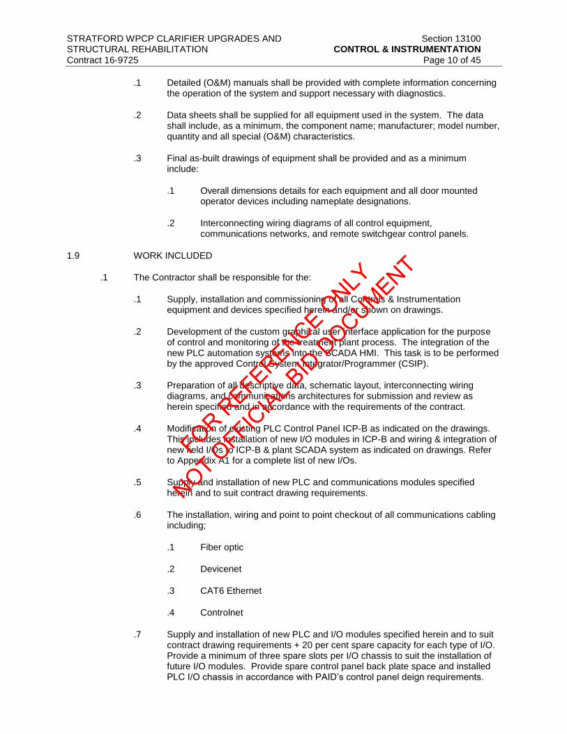
STRATFORD WPCP CLARIFIER UPGRADES AND Section 13100 STRUCTURAL REHABILITATION CONTROL & INSTRUMENTATION
Contract 16-9725 Page 10 of 45
.1 Detailed (O&M) manuals shall be provided with complete information concerning
the operation of the system and support necessary with diagnostics.
.2 Data sheets shall be supplied for all equipment used in the system. The data shall include, as a minimum, the component name; manufacturer; model number, quantity and all special (O&M) characteristics.
.3 Final as-built drawings of equipment shall be provided and as a minimum include:
.1 Overall dimensions details for each equipment and all door mounted operator devices including nameplate designations.
.2 Interconnecting wiring diagrams of all control equipment, communications networks, and remote switchgear control panels.
1.9 WORK INCLUDED
.1 The Contractor shall be responsible for the:
.1 Supply, installation and commissioning of all Controls & Instrumentation equipment and devices specified herein and/or shown on drawings.
.2 Development of the custom graphical user interface application for the purpose of control and monitoring of the treatment plant process. The integration of the new PLC automation systems into the SCADA HMI. This task is to be performed by the approved Control System Integrator/Programmer (CSIP).
.3 Preparation of all descriptive data, schematic layout, interconnecting wiring diagrams, and communications architectures for submission and review as herein specified and in accordance with the requirements of the contract.
.4 Modification of existing PLC Control Panel ICP-B as indicated on the drawings. This includes installation of new I/O modules in ICP-B and wiring & integration of new field I/Os to ICP-B & plant SCADA system as indicated on drawings. Refer to Appendix A1 for a complete list of new I/Os.
.5 Supply and installation of new PLC and communications modules specified herein and to suit contract drawing requirements.
.6 The installation, wiring and point to point checkout of all communications cabling including;
.1 Fiber optic
.2 Devicenet
.3 CAT6 Ethernet
.4 Controlnet
.7 Supply and installation of new PLC and I/O modules specified herein and to suit contract drawing requirements + 20 per cent spare capacity for each type of I/O. Provide a minimum of three spare slots per I/O chassis to suit the installation of future I/O modules. Provide spare control panel back plate space and installed PLC I/O chassis in accordance with PAID’s control panel deign requirements.
FOR REFERENCE O
NLY
NOT OFFIC
IAL B
ID D
OCUMENT

STRATFORD WPCP CLARIFIER UPGRADES AND Section 13100 STRUCTURAL REHABILITATION CONTROL & INSTRUMENTATION
Contract 16-9725 Page 11 of 45
.8 The Contractor shall provide a “test” program for the new automation hardware to
demonstrate the functionality of all the physical I/O, virtual I/O, located in the respective automation hardware and available via communications networks. The individual test programs shall demonstrate that the new PLC and automation hardware located in the new PLC panels specified in this section are able to monitor and control all local I/O. The Contractor must demonstrate that all PLC control panels that are equipped with Devicenet, Controlnet and/or Modbus communications modules are able to read/write/control all communications based I/O.
.9 Installation of wiring and wiring terminations to suit connection of field devices as shown on contract drawings.
.10 Testing, calibration, and commissioning of each signal loop.
.11 Supply and installation of all Terminal Blocks, control wiring, and auxiliary relays as shown on the drawings.
.12 The installation, wiring and point by point checkout of proposed field devices and instrumentation.
.13 The installation and wiring of all control and instrumentation equipment supplied under this contract.
.14 Supervision, calibration and communications systems checkout for remote switchgear control systems in the field to the Engineer’s satisfaction. The Contractor will be responsible for complete communications and automation system verification, and submit to the Engineer in writing (typed) verification and results of said communications and automation checkout, including details of automation testing and communications settings of equipment, prior to commissioning.
.15 Provide complete record drawings. Drawings to be produced using AutoCAD Version 2008, program and supplied to the customer on CD ROM. Also provide one print set of reproducible record drawings (size A1). The Contractor shall also be responsible for providing detailed wiring diagrams, and equipment manual, upon satisfactory commissioning and certification of work.
.16 The installation, wiring and point by point checkout of proposed communications networks including status and control functions from the respective switchgear control panels.
.17 The installation and wiring of all control and instrumentation equipment supplied under this contract.
.18 Division 16 to provide power to all electrical equipment whether equipment supplied by this Division or by others, or pre-selected. Provide local disconnect switches (fused or un-fused) as required by code whether shown or not. Coordinate this equipment supply and wiring with the Electrical Contractor.
.19 Commissioning of all equipment to be by the manufacturer’s representative.
.20 Installation of wiring and wiring terminations to suit connection of field devices as shown on contract drawings.
FOR REFERENCE O
NLY
NOT OFFIC
IAL B
ID D
OCUMENT

STRATFORD WPCP CLARIFIER UPGRADES AND Section 13100 STRUCTURAL REHABILITATION CONTROL & INSTRUMENTATION
Contract 16-9725 Page 12 of 45
.21 Testing, and commissioning of communications networks including verification of
communications from the PLC’s and Remote I/O to all devices located on the respective remote networks.
.22 Supply and installation of all Terminal Blocks, control wiring, and auxiliary relays as shown on the drawings.
.23 Detailed control loop wiring drawings for the proposed hardware in AutoCad v.2008 as per contract drawings.
1.10 STANDARDS
.1 Comply with the requirements of the latest edition of the applicable CSA Standards, the requirements of the Authorities, Federal, Provincial and Municipal Codes, the applicable standards of the Underwriter’s Association and all other authorities having jurisdiction. These codes and regulations constitute an integral part of these Specifications. In case of conflict, the codes take precedence over the Contract Drawings.
1.11 COORDINATION
.1 It will be the responsibility of the Contractor to coordinate work to be wired under this division.
.2 The Contractor will coordinate work with other Divisions where there is an impact or overlap of work with this Division.
.3 Ensure that other Divisions provide all necessary material and work required by this Division for the installation of equipment and wire, which falls under the responsibility of this division.
.4 Conform with Division 1.
1.12 CONTROL SYSTEM SUPPLIER
.1 The acceptable Control System Supplier (CSS) shall install complete controls, instrumentation, SCADA System Computer hardware, SCADA system software, PLC programming software, reporting software, alarm software, PLC automation, remote I/O modules and communications system. The acceptable CSS for Division 13 shall be:
.1 Summa Engineering Ltd.
.2 The CSS is required to provide all hardware and software indicated in this section.
.3 Equipment and software furnished under this section and under other related sections shall be designed with the exception of the vendor provided equipment, coordinated, and supplied by a single manufacturer or supplier, hereinafter referred to as the CSS. The CSS shall be regularly engaged in the business of supplying computer-based monitoring, control, and data acquisition systems. The Contractor shall utilize the services of the CSS to coordinate all control system related items, to check-out and calibrate instruments, and to perform all testing, training, and startup activities specified to be provided
.4 The acceptable CSS shall provide proof being CSA certified to suit the custom fabrication of the control panels specified herein and show on the drawings when requested by the engineer. The facility must be wholly owned by the CSS and may not be a subsidiary company or sub-contractor. The occupancy of the CSA certified fabrication facility is to
FOR REFERENCE O
NLY
NOT OFFIC
IAL B
ID D
OCUMENT
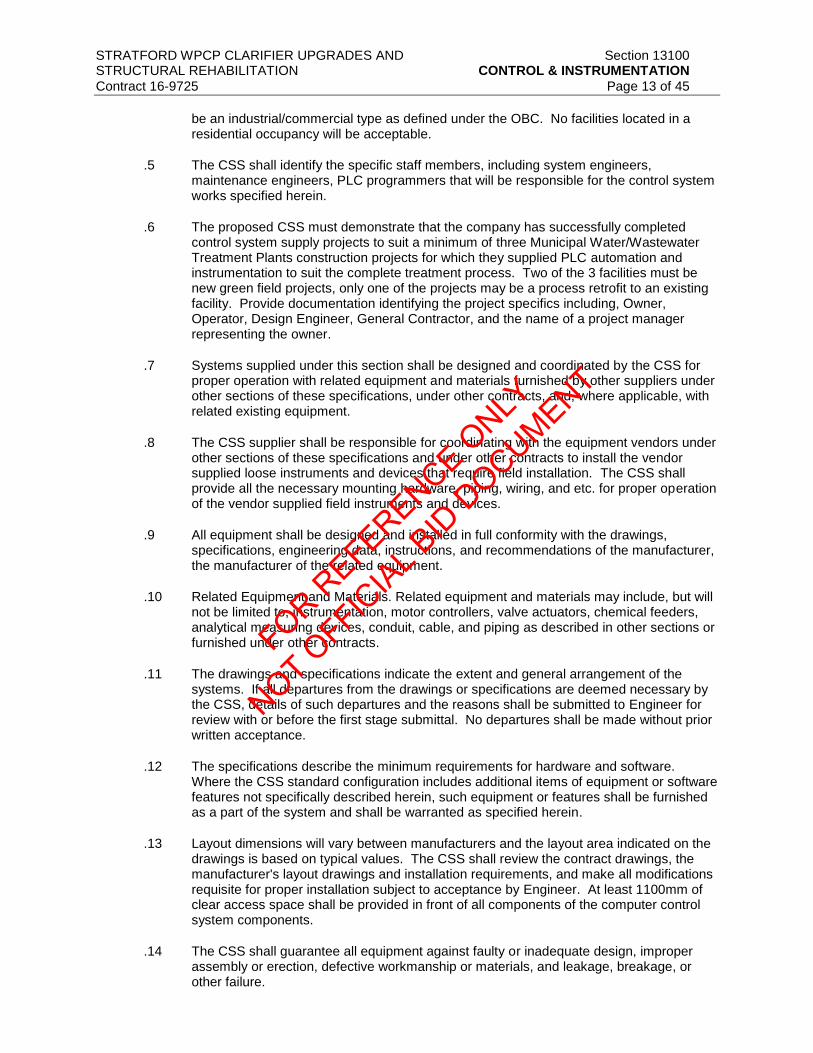
STRATFORD WPCP CLARIFIER UPGRADES AND Section 13100 STRUCTURAL REHABILITATION CONTROL & INSTRUMENTATION
Contract 16-9725 Page 13 of 45
be an industrial/commercial type as defined under the OBC. No facilities located in a residential occupancy will be acceptable.
.5 The CSS shall identify the specific staff members, including system engineers, maintenance engineers, PLC programmers that will be responsible for the control system works specified herein.
.6 The proposed CSS must demonstrate that the company has successfully completed control system supply projects to suit a minimum of three Municipal Water/Wastewater Treatment Plants construction projects for which they supplied PLC automation and instrumentation to suit the complete treatment process. Two of the 3 facilities must be new green field projects, only one of the projects may be a process retrofit to an existing facility. Provide documentation identifying the project specifics including, Owner, Operator, Design Engineer, General Contractor, and the name of a project manager representing the owner.
.7 Systems supplied under this section shall be designed and coordinated by the CSS for proper operation with related equipment and materials furnished by other suppliers under other sections of these specifications, under other contracts, and, where applicable, with related existing equipment.
.8 The CSS supplier shall be responsible for coordinating with the equipment vendors under other sections of these specifications and under other contracts to install the vendor supplied loose instruments and devices that require field installation. The CSS shall provide all the necessary mounting hardware, piping, wiring, and etc. for proper operation of the vendor supplied field instruments and devices.
.9 All equipment shall be designed and installed in full conformity with the drawings, specifications, engineering data, instructions, and recommendations of the manufacturer, the manufacturer of the related equipment.
.10 Related Equipment and Materials. Related equipment and materials may include, but will not be limited to, instrumentation, motor controllers, valve actuators, chemical feeders, analytical measuring devices, conduit, cable, and piping as described in other sections or furnished under other contracts.
.11 The drawings and specifications indicate the extent and general arrangement of the systems. If all departures from the drawings or specifications are deemed necessary by the CSS, details of such departures and the reasons shall be submitted to Engineer for review with or before the first stage submittal. No departures shall be made without prior written acceptance.
.12 The specifications describe the minimum requirements for hardware and software. Where the CSS standard configuration includes additional items of equipment or software features not specifically described herein, such equipment or features shall be furnished as a part of the system and shall be warranted as specified herein.
.13 Layout dimensions will vary between manufacturers and the layout area indicated on the drawings is based on typical values. The CSS shall review the contract drawings, the manufacturer's layout drawings and installation requirements, and make all modifications requisite for proper installation subject to acceptance by Engineer. At least 1100mm of clear access space shall be provided in front of all components of the computer control system components.
.14 The CSS shall guarantee all equipment against faulty or inadequate design, improper assembly or erection, defective workmanship or materials, and leakage, breakage, or other failure.
FOR REFERENCE O
NLY
NOT OFFIC
IAL B
ID D
OCUMENT

STRATFORD WPCP CLARIFIER UPGRADES AND Section 13100 STRUCTURAL REHABILITATION CONTROL & INSTRUMENTATION
Contract 16-9725 Page 14 of 45
1.13 CONTROL SYSTEM INTEGRATOR/PROGRAMMER
.1 The Contractor shall retain a Control System Integrator/Programmer (CSIP) to provide all PLC/SCADA programming as stated in section 13110 and inclusive of the following:
.1 Prepare detailed control narrative based on process narrative.
.2 Programming of all PLC’s SCADA Computers and local Ethernet Communications Network.
.3 Integration of auxiliary network systems that are installed and pre-configured by the Contractor.
.4 Development of graphical user interface applications to suit the SCADA Computers and related custom HMI SCADA application
.5 Verification of all I/O on site.
.6 Assist with start-up & commissioning of all PLC/SCADA controlled equipment.
.7 SAT – Complete system automation and SCADA software application
.8 PLC/SCADA Programming documentation
.9 PLC/SCADA Manual
.10 PLC/SCADA Training – on site
.2 The Contractor shall provide the following:
.1 Verification and demonstration of all I/O on site.
.2 Start-up & commissioning of all PLC/SCADA controlled equipment.
.3 Factory Acceptance Testing and Site Acceptance Testing of all control panels provided by the Contractor.
1.14 JOB CONDITIONS
.1 Examine the site and contract documents in accordance with Instructions to Bidders.
.2 Attend site visits during the tender period to verify the existing conditions to suit the required works shown on the drawings and specified herein.
1.15 QUALITY ASSURANCE FOR COPPER CABLES
.1 The materials, design, and workmanship employed in the manufacture of all equipment shall conform to the applicable standards for Copper cables.
.2 The cable must meet the requirements of C (UL) CEC approved as communications cables meeting the requirements for the Bi-National Standard CSA C22.2 No. 214/UL 444 and Section 60 of the Canadian Electrical Code, Part 1 (CEC). The C (UL) cable designation (and its meaning) would be one of the following:
.1 CMP – Cable meeting CSA FT6 or UL 910
.2 CMR – Cable meeting UL 1666
FOR REFERENCE O
NLY
NOT OFFIC
IAL B
ID D
OCUMENT

STRATFORD WPCP CLARIFIER UPGRADES AND Section 13100 STRUCTURAL REHABILITATION CONTROL & INSTRUMENTATION
Contract 16-9725 Page 15 of 45
.3 CMG – Cable meeting CSA FT4
.4 CM – Cable meeting UL 1581, Section 1160 (Vertical Tray)
.5 CMX – Cable meeting UP 1581, Section 1080 (VW-1)
.6 CMH – Cable meeting CSA FTI
1.16 QUALITY ASSURANCE FOR ETHERNET CABLES
.1 The materials, design and workmanship employed in the manufacture of all equipment shall conform to the applicable standards for Ethernet Cables, Category 5e type:
.1 ANSI/TIA/569-A-1-2000 – Surface Raceways
.2 ANSI/EIA/TIA-569-A-2-2000 – Furniture Pathways and Spaces
.3 ANSI/EIA/TIA-569-A-3-2000 – Access Floors
.4 ANSI/EIA/TIAAAA-569-A-4-2000 – Poke Thru Fittings
.5 ANSI/EIA/TIA/569-A-7-2001 – Cable Trays and Wire ways
2 PRODUCTS
2.1 GENERAL REQUIREMENTS
.1 Electrically heat traced sensing lines for instruments with sensing lines liable to freezing.
.2 Unless otherwise shown or specified, provide instruments located in hazardous areas with Ontario Electrical Code ratings for class, group, and division as shown.
.3 All line voltage powered instruments are to be suitable for a 120VAC power supply. All line voltage AC powered instrument not CSA certified must bear an ESA Special Approvals Branch label.
.4 Normal instrument and control power supply for the Contract is 120VAC. Emergency power supply is from associated UPS. Provide all line powered instruments suitable for use on these supplies with appropriate CSA approval. All UPS power feeds are to be sourced from the treatment plant existing emergency generator electrical distribution system.
.5 As applicable, instrument control output is to be from 4 to 20 mA, linear, isolated capable of driving a maximum load of 750ohms, unless otherwise specified.
.6 Provide all the necessary mounting hardware, electrical connections, transducer junction boxes, power supplies, and all accessory items or options required to satisfy each application.
.7 Provide corrosion resistant stainless steel or epoxy coated screws, bolts, fasteners, etc. in all applications.
.8 Provide all special instrumentation communication cables, transducer cables, power cables, process sensing/sampling lines and capillary tubing in field measured lengths without joins as required by manufacturer. Allow adequate cable/capillary etc. to allow removal of instrument/transducer from process. Agree instrument-mounting locations with Engineer to ensure accurate field measurements.
FOR REFERENCE O
NLY
NOT OFFIC
IAL B
ID D
OCUMENT

STRATFORD WPCP CLARIFIER UPGRADES AND Section 13100 STRUCTURAL REHABILITATION CONTROL & INSTRUMENTATION
Contract 16-9725 Page 16 of 45
.9 Provide mechanical protection for capillaries and transducer cables and adequately
secure to eliminate sagging.
.10 All instruments shall be provided with process isolation valves. Valves must be utilized on all instrument lines for easy removal without disruption to the process.
.11 All readouts, indicators, recorders, etc., shall be in metric units, whether shown or not and in engineering scales. All final units, ranges, set points, colours, etc., will be finalized on the shop drawings.
.12 The Contractor shall be responsible for supplying all required communications setup and/or wiring, etc., and all other appurtenances which may be required, in order for the entire control and instrumentation system to operate as intended by this specification and as designed. Unless specifically stated otherwise, all control and readout signals, etc., shall be linear.
.13 For wiring, see Division 16.
.14 Equipment specified includes automation hardware, communications hardware and control equipment (including panels/enclosures) as specified herein and shown on drawings.
.15 Without limitation to the following sections of this item, the equipment supplied shall be complete with all accessory items, whether specifically mentioned or not, so as to provide completeness of installation, and operation as intended.
.16 The equipment specified shall generally be an "all electronic" control system, with linear isolated outputs from all instruments, 4-20 mA DC unless otherwise noted, and suitable for 115 volts, 60Hz, single phase operation.
.17 No instruments shall be included in the design which utilize mercury or all other highly toxic substances, which through error or otherwise may enter and endanger the water supply.
.18 All instruments and control elements shall be fully pre-wired and pre-piped in the factory and shall be equipped complete with terminal, terminal blocks and taps suitable for direct connection in the field.
.19 Mounting brackets, hooks, plates, screws, bolts, anchors, etc., shall be stainless steel or epoxy coated and of sufficient size to permanently mount the equipment.
.20 All process controls and instrumentation shall be complete with all necessary appurtenances to perform the functions indicated on the control schematics and electrical drawings with respect to inputs, outputs, etc.
.21 Equipment specified includes instrumentation (including appropriate mounting hardware) and control equipment (including panels/enclosures) as specified herein and shown on drawings. Primary devices, transmitters, receivers, signal protection, conditioning equipment, indicators, switches (pressure/flow/temp.) etc. is to be included.
.22 The CSS shall be responsible for providing ventilation and/or dedicated cooling systems for all the control panels supplied by the CSS. Size the ventilation/cooling systems to provide sufficient air changes to dissipate excess heat generated by internal components. Maintain panel ambient temperature to suit the operating requirements of the internal components.
2.2 SERVICE CONDITIONS AND ENVIRONMENTAL REQUIREMENTS
FOR REFERENCE O
NLY
NOT OFFIC
IAL B
ID D
OCUMENT

STRATFORD WPCP CLARIFIER UPGRADES AND Section 13100 STRUCTURAL REHABILITATION CONTROL & INSTRUMENTATION
Contract 16-9725 Page 17 of 45
.1 The equipment provided for the control system shall be suitable for the service conditions
specified in the equipment sections.
.2 All equipment shall be designed and selected to operate without degradation in performance throughout the environmental extremes specified. Equipment shall be designed to prevent the generation of electromagnetic and radio frequency interference and shall be in compliance with FCC Rules and Regulations, Part 15, for Class A computing devices.
.3 All control system equipment located in air conditioned rooms shall be suitable for operation in ambient temperatures from 10°C to 35°C and a relative humidity of 10 to 80 per cent, noncondensing. All equipment located in non air conditioned indoor areas shall be suitable for an ambient temperature range of 0°C to 50°C and a relative humidity of 10 to 95 per cent, noncondensing. All equipment located outdoors shall be suitable for operation in an ambient temperature range -20°C to 60°C and a relative humidity of 5 to 100 per cent. Heaters and air conditioning/cooling equipment shall be provided where essential to maintain equipment within its manufacturer-recommended operating ranges.
.4 All control system equipment will be installed in areas without anti-static floor construction and without any provisions for control of particulates or corrosive gases other than ordinary office-type HVAC filtering. SYSTEM SUPPLIER shall furnish any additional air cleaning equipment, anti-static chair pads, or other protective measures necessary for proper operation of the system.
.5 All input/output hardware shall meet or exceed, without false operation, all requirements of NEMA ICS-1-109.60, Electrical Noise Tests.
.6 The equivalent "A" weighted sound level for all system equipment located in the treatment plant control room, except printers, shall not exceed 35 dBA. The sound level for printers shall not exceed 65 dBA. Sound reduction enclosures shall be provided where necessary to comply with these limits.
2.3 PLC & AUTOMATION EQUIPMENT
.1 This project requires modification of existing PLC control panel, ICP-B, in chemical building to suit new I/Os in Appendix A1.
.2 The contractor is to supply, install, test, and commission new PLC components in ICP-B as indicated on contract drawings. Provide control panel components to suit the integration of the new process system I/O and communications, including I/O required to suit future process applications. New control panel components shall include:
.1 GE Fanus Series 90-30 Hardware:
.1 I/O Modules
.1 Digital Input Module: GE Fanuc IC693MDL240
.2 Digital Output Module: GE Fanuc IC693MDL930
.3 Provide Removable Terminal Blocks (RTB’s) for all I/O modules.
.2 One spare wiring arm for each I/O module supplied.
.3 All Inputs shall be optically isolated.
FOR REFERENCE O
NLY
NOT OFFIC
IAL B
ID D
OCUMENT

STRATFORD WPCP CLARIFIER UPGRADES AND Section 13100 STRUCTURAL REHABILITATION CONTROL & INSTRUMENTATION
Contract 16-9725 Page 18 of 45
.4 All discrete Outputs shall transition through DIN rail mounted interposing
relays complete with 2A, 120VAC dry contacts and LED operation indication.
.5 Analog transmitters located outside of the main building must transition through a 24VDC loop Isolator/surge suppressor. Isolator to be 24VDC DIN rail mounted, Pribusin or equal.
.2 All Allen Bradley connection cables to suit the communications requirements identified on the SCADA architecture drawings including cables, connectors, for Devicenet, Controlnet, and Ethernet communications networks.
.3 Provide all communications cables to suit control architecture as required.
.4 Supply and install quantity of I/O modules to suit I/O for all field devices and transmitters as shown on control drawings, plus 20 per cent spare capacity for each type of I/O. 20 per cent spare capacity to be calculated based on I/O requirements for field devices and instrumentation terminated as per this contract and including instrumentation to be terminated as part of future works.
.5 I/O modules identified for future/spare capacity I/O on the control shop drawings shall all be brought to terminal blocks.
2.4 SYSTEM SOFTWARE CONFIGURATION
.1 The existing SCADA HMI and the system software will be configured by the CSIP to include screens for new equipment as detailed in section 13110. The CSS shall be responsible for the following configuration support tasks:
.1 Furnish and install the necessary operating system software, utilities, and all standard software packages. All software provided shall be fully configured for use as specified herein and in related sections. This configuration should include but not be limited to, security access from the Administrator functionality to the Operator functions, printing functions (including graphics, reports, system documentation parameters, etc.), reporting functions and historical interface and historical data accessibility.
.2 Configure the hardware and provide any necessary firmware or software programming associated with the hardware, configuration such as DCU, PLC, and RTU device address assignments.
.3 Provide the services of an experienced applications engineer for two (2) 8-hour day visits, at Owner’s facilities, to assist with the configuration. One of these visits shall be scheduled to coincide with the delivery of equipment for configuration. The remaining visits shall be scheduled with Engineer and Owner.
.4 Provide the services of the applications engineer for telephone consultation and trouble shooting from System Supplier’s facility for twenty-four (24) hours.
.5 Provide early shipment of the terminal and hardware equipment for configuration of the system as defined herein. This equipment shall be delivered to Owner’s offices, but not before submittal information and drawings for the equipment have been approved. System Supplier shall also be responsible for subsequent retransport of this equipment to the project site.
.6 Provide complete startup, checkout, and calibration of all system hardware and I/O specified.
2.5 SOFTWARE DOCUMENTATION
FOR REFERENCE O
NLY
NOT OFFIC
IAL B
ID D
OCUMENT

STRATFORD WPCP CLARIFIER UPGRADES AND Section 13100 STRUCTURAL REHABILITATION CONTROL & INSTRUMENTATION
Contract 16-9725 Page 19 of 45
.1 CSS shall furnish complete documentation on all software supplied with the system
specified herein. Operating systems, compilers, assemblers, and utility and diagnostic programs that are standard commercial products of third parties need not be included in the magnetic/optical media backup. Software documentation shall consist of the following principal items.
.1 One backup set of any integrated circuit or solid-state memory-based plug-in firmware used.
.2 Two complete backup copies of system and application software in installable/executable format on magnetic/optical media compatible with the system furnished.
.3 Two complete backup copies of all purpose made software c/w source code and optical/media.
.4 Three sets of user reference manuals for all standard system and application software.
.5 One set of user reference manuals for all operating system software.
.6 Three sets of printed as-built reference documentation for any special software provided specifically for this contract.
.7 One set of above on magnetic/optical media compatible with the system furnished.
.8 For each licensed software product, all documentation provided by the product manufacturer shall be provided. This includes all reference manuals and any other documents that were provided by the manufacturer. There should be one set of this documentation for each and every piece of equipment provided. Multiple pieces of similar equipment or software require multiple copies of this documentation.
2.6 SOFTWARE LICENSE
.1 All software programs supplied as a standard part of System Supplier’s products for this project shall be licensed to Owner for use on the system specified herein. Such license shall not restrict Owner from using the software on the system provided hereunder or its replacement. Owner shall have the right to make copies of the software for use on the system provided. Specific requirements of System Supplier’s software license are subject to review and approval by Owner and Engineer.
2.7 INSTRUMENTATION, CONTROL, COMMUNICATION, AND SPECIAL FIELD WIRING
.1 Conform to the requirements of Division 16.
.2 Run all wiring in conduit or duct (underground wire) unless otherwise specified. Refer to this division and to the drawings for additional information, requirements and details.
.3 Provide minimum 20 per cent spare wiring or two conductors (one pair) whichever is greater for each control conduit. Spare control wire shall be tagged as spare at both ends.
.4 All wires must be tagged with pre-numbered slip-on markers. Allow for up to 10 characters per individual wire. No wrap around markers will be accepted.
.5 Control Wiring (Field)
.1 All control wiring to be stranded, annealed copper conductors, 600V minimum rating 14 AWG, RW90 XLPE, 600V rated conductors to be provided.
FOR REFERENCE O
NLY
NOT OFFIC
IAL B
ID D
OCUMENT

STRATFORD WPCP CLARIFIER UPGRADES AND Section 13100 STRUCTURAL REHABILITATION CONTROL & INSTRUMENTATION
Contract 16-9725 Page 20 of 45
.2 Where conductors to be buried in conduit 14 AWG, RWU90, XLPE, 600V rated
conductors to be provided.
.6 Instrumentation Cable (Field)
.1 Cable to be 300 V rated and meet CSA, C22.2 No. 239 standard with the following features:
.1 Seven strand copper conductor with TW75 (-40°C) 105°C dry PVC insulation formed into pairs or triads.
.2 Aluminum/polyester tape shield over individual pairs or triads.
.3 Individual shield, seven strand tinned copper drain wire.
.4 Aluminum/polyester tape shield over cable.
.5 Overall shield, seven strand tinned copper drain wire.
.6 Ripcord.
.7 90°C (-40°C) FRPVC jacket.
.2 Cable to be as manufactured by SHAWFLEX LTD. or BELDEN LTD.
.7 Communication and Special Wire and Cable (Field)
.1 The Contractor shall provide all wiring and cable, including connectors, plugs and termination devices required for the wiring of the systems and equipment shown on the drawings, unless otherwise specified.
.2 Provide quantities and lengths of cable and wire type as recommended by the system equipment manufacturers. Do not de-rate any cabling and wire. No wire/cable to be sized less than 18 AWG unless approved by the Engineer or unless a specific requirement of the equipment manufacturer.
.3 Coordinate with the manufacturer and other sections of these specifications to ensure proper conduit type (i.e. metal) and sizes are provided.
.4 All cables and wire to be continuous runs.
.5 Provide, as part of shop drawing submittal, cable and wire specifications and data for each system. Include written proof that cable and wire meets requirements of equipment supplier.
.6 Any wire and cable installed that does not meet the wiring specifications of the equipment manufacturer shall be removed and replaced (including conduits, if necessary), at the Contractor’s expense.
.8 Devicenet Cable
.1 Supply and install Devicenet network cable in accordance with PLC scanner module and Devicenet capable equipment manufacturer’s recommended installation requirements.
.2 Coordinate Devicenet communications trunk cable length and communications speed to suit the physical Locations of the PLC and valve actuators.
FOR REFERENCE O
NLY
NOT OFFIC
IAL B
ID D
OCUMENT

STRATFORD WPCP CLARIFIER UPGRADES AND Section 13100 STRUCTURAL REHABILITATION CONTROL & INSTRUMENTATION
Contract 16-9725 Page 21 of 45
.3 Coordinate the proposed Devicenet topology with the valve manufacturer’s
requirements.
.4 Supply and install continuous lengths of Devicenet trunk cable to suit the SCADA architecture.
.5 Supply and install the Devicenet communications cable in a dedicated PVC encapsulated rigid metal conduit.
.6 Provide a dedicated 24VDC power supply, in the respective control panel equipped with a Devicenet module to suit the Devicenet communications application. Coordinate the size of the PLC control panel 24VDC power supply to suit the Devicenet power requirements. Supply a larger capacity 24VDC power supply to suit the network load as required.
.7 All Devicenet communications networks installations must conform with Allen Bradley Publication 1485-DN-6.7.2 DeviceNet Cable System Planning and Installation Manual and Allen Bradley Publication DNET-UM072C-EN-P Devicenet Media Design and Installation guide.
.8 Provide a detailed communications architecture schematic as part of the shop drawing submittals that details all media interconnections and components to suit all devicenet networks.
.9 Acceptable Devicenet Cabling Terminations and Connectors: Brad Harrison
.10 Acceptable Devicenet cable:
.1 Allen Bradley 1485C
.2 Belden 7897A
.9 Controlnet Cable
.1 Supply and install Controlnet network media and components in accordance with PLC scanner module and remote controlnet I/O devices recommended installation requirements.
.2 Provide Controlnet network connections, hardware and communications cables installations in accordance with Allen Bradley Publication CNET-IN002A-EN-P, Controlnet Coax Media Planning and Installation Guide.
.3 All Contrologix network components, and cabling shall be by Allen Bradley in accordance with Allen Bradley Publication AG-PA002D-EN-P Controlnet Media System
.4 Coordinate Controlnet communications trunk cable length and communications speed to suit the physical Locations of the PLC and remote I/O.
.5 Supply and install continuous lengths of Controlnet trunk cable to suit the SCADA architecture.
.6 Acceptable Controlnet cable:
.1 RG-6 Quad Shield Coax - Belden 3092A
FOR REFERENCE O
NLY
NOT OFFIC
IAL B
ID D
OCUMENT

STRATFORD WPCP CLARIFIER UPGRADES AND Section 13100 STRUCTURAL REHABILITATION CONTROL & INSTRUMENTATION
Contract 16-9725 Page 22 of 45
.7 Supply and install the Controlnet communications cable in dedicated PVC
encapsulated rigid metal conduit.
.8 Provide a detailed communications architecture schematic as part of the shop drawing submittals that details all media interconnections and components to suit all Controlnet networks.
2.8 FIELD DEVICES AND CONTROL EQUIPMENT
.1 Unless specified otherwise, transmitters shall be two-wire, suitable for operation on 24VDC, with 4-20 mA DC linear output, complete with direct reading local indicators in engineering scales.
.2 Calibration and scale range data indicated may vary during shop drawing review.
.3 Provide quantity and tagging to suit the drawings.
.4 Acceptable manufacturers of control equipment transmitters shall be as specified for the respective field devices.
.1 Control Relays:
.1 Relays indicated to be provided in panels, enclosures, or systems furnished under this section shall be of the plug-in socket base type with dustproof plastic enclosures unless noted otherwise. Relays shall be ULC recognized and shall have not less than double-pole, double-throw contacts.
.2 Control circuit relays shall have silver cadmium oxide contacts rated 10 amperes at 12 VAC. Electronic switching-duty relays shall have gold-plated or gold alloy contacts suitable for use with low-level signals. Relays used for computer input, alarm input, or indicating light service shall have contacts rated at least three amperes. . Latching and special purpose relays shall be as required for the specific application. Unless otherwise indicated, all relays shall have an integral pilot light that illuminates to indicate an energized condition.
.3 Heavy duty type, electrically held.
.4 11 pin, DIN rail mounted.
.5 Contacts: DPDT 1 NO, rated 8A at 120V.
.6 LED illumination to indicate relay operation.
.7 Supply Voltage: 24VDC
.8 Approved Manufacturer:
.1 Releco
.2 Struthers-Dunn
.3 Potter & Brumfield
.4 OMRON
FOR REFERENCE O
NLY
NOT OFFIC
IAL B
ID D
OCUMENT

STRATFORD WPCP CLARIFIER UPGRADES AND Section 13100 STRUCTURAL REHABILITATION CONTROL & INSTRUMENTATION
Contract 16-9725 Page 23 of 45
.5 Approved Equal
.2 Timing Relays (General):
.1 Heavy duty type, solid state, electrically held, automatic reset after de-energizing.
.2 Time delay relays shall have dials or switch settings engraved in seconds and shall have timing repeatability of ±2 per cent of setting
.3 Latching and special purpose relays shall be as required for the specific application. Unless otherwise indicated, all relays shall have an integral pilot light that illuminates to indicate an energized condition
.4 Range and setting to be as shown and field adjustable.
.5 8 or 11 pin, DIN rail mounted.
.6 Contacts: 2 NO and 2 NC, rated 8A at 120V.
.7 LED illumination to indicate timing start.
.8 LED illumination to indicate relay operation.
.9 Supply voltage: 120VAC.
.10 Approved Manufacturer:
.1 Releco
.2 Struthers-Dunn
.3 Potter & Brumfield
.4 OMRON
.5 Approved Equal
.3 Panel Circuit Breakers:
.1 Supply and install rail mount type circuit breakers as shown on drawings, suitable for voltage shown and load requirements.
.2 Breakers to be Thermal-Magnetic type complete with auxiliary contacts, (close on trip) on/off switch, test switch, and trip indication.
.3 Breakers to be ETA Series 2210-T.
.4 Loop Isolators (ISO)
.1 Provide and install loop isolation for 4-20mA analogs where more than one device is receiving the analog as an input.
.2 Input to output isolation to take place through an optical coupler and input/output to power isolation to take place through isolated power supplies.
FOR REFERENCE O
NLY
NOT OFFIC
IAL B
ID D
OCUMENT

STRATFORD WPCP CLARIFIER UPGRADES AND Section 13100 STRUCTURAL REHABILITATION CONTROL & INSTRUMENTATION
Contract 16-9725 Page 24 of 45
.3 Operating voltage: 24VDC.
.4 Acceptable product:
.1 PRIBUSIN ITC-XX or approved Phoenix Contact equal.
.5 24V DC Power Supply;
.1 Supply and install 24VDC power supplies as shown on drawings or as required by the instrumentation provided.
.2 Provide dedicated 24VC power supplies to suit all Devicenet communications networks applications. Devicenet power supply type and size to be in accordance with Allen Bradley Devicenet design and application publications.
.3 Regulated dc power supplies for instrument loops shall be designed and arranged so that loss of one supply does not affect any instrument loop or system. Power supplies shall be suitable for an input voltage variation of ±10 percent, and the supply output shall be fused or shortcircuit protected. Output voltage regulation shall be as required by the instrumentation equipment supplied. Multiloop or multisystem power supplies will be acceptable if backup power supply units are provided which will automatically supply the load upon failure of the primary supply. The backup supply systems shall be designed so either the primary or the backup supply can be removed, repaired, and returned to service without disrupting the instrument system operation
.4 Provide dual redundant 24VC power supplies to suit each application. Provide a redundancy module to suit switching of the power source between the primary and secondary power supply
.5 Power supplies to be complete with the following features:
.1 Input: 120VAC, 60Hz 5A minimum or greater as required to suit the application.
.2 Output: adjustable 24-30 (External) VDC regulated supply at 3 amps output with terminal screw connections.
.3 Stability: .2 per cent
.4 Mounting: Sub panel mounted
.5 Approval: CSA
.6 Enclosure: General Purpose EEMAC 1
.7 Protection: Short circuit and over current
.8 Options: Two wire power supply output (24VDC)
.9 Provide integral protection to suit the ability to parallel the DC output with multiple DC power supplies.
.10 Provide an auxiliary 1A, 120VC, auxiliary contact to suit power supply general alarm.
FOR REFERENCE O
NLY
NOT OFFIC
IAL B
ID D
OCUMENT

STRATFORD WPCP CLARIFIER UPGRADES AND Section 13100 STRUCTURAL REHABILITATION CONTROL & INSTRUMENTATION
Contract 16-9725 Page 25 of 45
.11 Manufacturer: Phoenix Contact Quint Power Type or approved
Pribusion equal.
.6 Intrinsically Safe Relays:
.1 Dual channel galvanically isolated intrinsically safe barrier with built-in amplifier to transfer discrete signals from a hazardous area to a safe area.
.2 Relays shall be solid-state electronic type in which the energy level of the sensing or actuation circuit is low enough to allow safe use in hazardous areas. Relays shall be located in non-hazardous areas
.3 Power Supply: 20-30VDC
.4 Input: Intrinsically safe
.5 Output: Two SPDT contacts rated 4.0 amps at 120VAC
.6 Acceptable Product
.1 Pepperl + FUCHS Model KFD2-SR2-Ex2.w
.2 Approved Equal
.7 Analyzers (AIT)
.1 To be supplied and installed in accordance with Section 13564 and 13569.
.2 To be wired for 120V power supply and control wiring associated with alarm set point contacts by Division 16.
.3 Wiring to suit installation location as directed by the Engineer.
.4 Sensor cable length to be coordinated so that wiring between the sensor and controller is without splices.
.5 If meter is not CSA, then it will require special inspection by the Electrical Safety Authority (ESA).
.8 Flow Indicator Transmitter (FIT)
.1 To be supplied and installed in accordance with Section 13566.
.2 All power and control wiring by Division 16.
.3 Output: Isolated 4-20mA
.4 Sensor cable length to be coordinated so that wiring between the sensor and controller is without splices.
.5 If any instrument or device is not CSA, then it will require special inspection by the Electrical Safety Authority (ESA). The Contractor shall coordinate and pay for each inspection as required.
.9 Mechanical Float Switches – water/wastewater
FOR REFERENCE O
NLY
NOT OFFIC
IAL B
ID D
OCUMENT

STRATFORD WPCP CLARIFIER UPGRADES AND Section 13100 STRUCTURAL REHABILITATION CONTROL & INSTRUMENTATION
Contract 16-9725 Page 26 of 45
.1 Non-Mercury, mechanical float switch, PVC encapsulated complete with
adjustable neoprene strain relief.
.2 Cable to be suitable for submersible installation.
.3 Contact Rating: SPDT, 10Amps 120V 1 NO and 1 NC contacts.
.4 CSA Certified. All float switches located in a class 1 area must transition thru an intrinsically safe wiring barrier.
.5 Acceptable Product:
.1 ITT Flygt ENM-10 “Float Switch”
.10 Liquid Level Detection Switches – Level Probe Type
.1 To be supplied and installed in accordance with Section 13563.
.2 Liquid Level Detection system based on multiple conductive probe sensors and electronic sensing to suit discrete indication of liquid level settings.
.3 Level control system shall consist of a multiple duel level relays, probe housing, suspension wire adaptor, and multiple level probe electrodes
.4 Level Relay Supply voltage: 120VAC, +/- 15%, 60Hz
.5 Level Relay Output Rating: 2A, 250VAC, 1 A 250VDC, SPDT
.6 Accuracy: +- 5 per cent at 1k ohm to 10k ohms
.7 Temperature range: -20°C to 50°C
.8 Probe Suspension Wire to be PVC insulated continuous length to the probe housing.
.9 Provide an adaptor kit to suit integration of the level probe wire and probe housing.
.10 Output: Isolated 4-20mA into 350 ohms
.11 CE/CSA approved
.12 Install level sensing Control Relays in the respective control panels
.13 NEMA 4X Corrosion resistant probe housing
.14 Acceptable Product: Gems Warrick
.11 Ultrasonic Level Measurement (LIT)
.1 To be supplied and installed in accordance with Section 13563
.2 Milltronics Multiranger 200 non contacting ultrasonic level measurement.
.3 Supply voltage: 120VAC, +/- 15 per cent, 60Hz
FOR REFERENCE O
NLY
NOT OFFIC
IAL B
ID D
OCUMENT

STRATFORD WPCP CLARIFIER UPGRADES AND Section 13100 STRUCTURAL REHABILITATION CONTROL & INSTRUMENTATION
Contract 16-9725 Page 27 of 45
.4 LCD Display
.5 Resolution: 0.1 per cent of range or 2mm
.6 Accuracy: 0.25 per cent or better
.7 Measurement range: 0.3 to 15m
.8 Temperature range: -20°C to 50°C
.9 Output: Isolated 4-20mA into 350 ohms
.10 CSA/FM approved
.11 Wire analog output to control panel
.12 Individual level transmitters shall be synchronized to each other, where level element wiring from the transmitters to the respective level elements are in close proximity or installed in the same conduit.
.13 NEMA 4 Wall mountable Enclosure
.12 Ultrasonic Level Primary Element: (LE)
.1 To be supplied and installed in accordance with Section 13563.
.2 XPS-15 transducer complete with factory supplied cable (without splice) for connection to the level indicator transmitter complete with 6° Beam Angle (up to 300m).
.3 RG-62 A/U Coaxial transducer cable to be installed in a dedicated metal conduit OR two cable in the same conduit provided the level indicator units are synchronized.
.4 Measurement range: 15m maximum
.5 Beam angle: 6°
.6 Housing: suitable for Class 1, Div 1
.7 Installation to suit manufactures specification (allow for ease of maintenance and cleaning).
.13 Flood Alarm Float Switch – LSH
.1 To be supplied and installed in accordance with Section 13563
.2 GEMS IMO liquid level switch, model LS 1900T complete with 6mm male NPT for threaded installation
.3 Float switch to be installed 100mm A.F.F.L. Float switch to be provided with stainless steel stem (length 600mm) and terminated in a PVC NEMA 4 junction box 610mm A.F.F.L.
.4 Stem and mounting – 316SS
.5 Float material: BUNA
FOR REFERENCE O
NLY
NOT OFFIC
IAL B
ID D
OCUMENT

STRATFORD WPCP CLARIFIER UPGRADES AND Section 13100 STRUCTURAL REHABILITATION CONTROL & INSTRUMENTATION
Contract 16-9725 Page 28 of 45
.6 Switch rating: SPST, 100VA, 120V
.14 Limit Switches - LS
.1 To be supplied and installed in accordance with Section 13565.
.2 NEMA 4 enclosure
.3 Vibration resistance 30G at (10-55Hz)
.4 Mechanical life 10 million operations
.5 2-SPDT 120VAC, 10A contacts
.6 Ambient temp range: -30°C to 70°C
.7 All construction including lever arm shall be of non corrosive material.
.8 Max. wire termination: 2 - # 12 AWG per terminal
.9 Approved manufacturer: Allen Bradley or Square D
.15 Pressure Switches: PS
.1 To be supplied and installed in accordance with Section 13563.
.2 Phosphor bronze bellows
.3 NEMA 4 enclosure
.4 Contact rated 10A, 120V
.5 Pressure connection: ¼” NPTF
.6 Range: 0 to 100 PSI with full range, Internal 0 – 100 per cent adjustable
.7 Provide isolation valves as shown on drawings
.8 Approved manufacturer: United Electric type J400K, Mercoid or Ashcroft.
.16 Signalling Devices
.1 Industrial Electric/Electronic Horn to be 120dB (adjustable), 120VAC, NEMA 4X/3R enclosure, acceptable product: Allen Bradley Type 855H or approved equal.
.2 Industrial Beacon to be 120VAC, Red Lens, Flashing Halogen Light, NEMA 4X/3R enclosure, mounting type to suit the application, acceptable product: Allen Bradley Type 855BM or approved equal
.17 Door Switches:
.1 Sentrol 2800T Magnetic Contacts – For Explosion Proof Installations
.2 GE - Industrial Wide Gap Surface Mount 2500 Series – For non-classified installations
FOR REFERENCE O
NLY
NOT OFFIC
IAL B
ID D
OCUMENT

STRATFORD WPCP CLARIFIER UPGRADES AND Section 13100 STRUCTURAL REHABILITATION CONTROL & INSTRUMENTATION
Contract 16-9725 Page 29 of 45
.3 GE Security 2202 Series overhead door magnetic contact to suit
overhead door installations.
.18 Pressure Indicator Transmitter (PIT)
.1 To be supplied and installed in accordance with Section 13563.
.2 Provide pressure range to suit the respective application.
.3 Diaphragm material: 316 Stainless Steel
.4 Digital Display: 5dig, 2 line LCD
.5 Housing: NEMA 4X
.6 Local adjustment: Zero & Span
.7 Surge suppression: Integral transient protection terminal block to suit IEEE 587
.8 Process Connections: ¼” NPT
.9 Low Pressure Applications - Working Pressure Range: 0 to 1034 kPa (150 PSIG)
.10 High Pressure Applications (Surge Tank) – Works Pressure Range: 0 to 3000 kPa (300 PSIG)
.11 Output: 4-20mA DC (linear) into 750 ohms, accuracy ± 0.2 per cent of span
.12 Provide 24V DC loop power supply
.13 Provide isolation valve, pressure rated hydraulic lines, pressure snubber and all required brackets and fittings.
.14 Approved Product: Rosemount Model 3051.
.19 Smoke Detector:
.1 Power Supply: 120VAC or 24VDC source from control panel
.2 ULC listed
.3 Contact rating 3.0A, 120VAC
.4 Acceptable Product:
.1 Edwards 517TH series
.2 Simplex Model 12098
.3 GE Interlogix ESL 500/500N Series
.4 GE Explosionproof Photoelectric Smoke Detector Model V9006
.20 Heat Detector:
FOR REFERENCE O
NLY
NOT OFFIC
IAL B
ID D
OCUMENT

STRATFORD WPCP CLARIFIER UPGRADES AND Section 13100 STRUCTURAL REHABILITATION CONTROL & INSTRUMENTATION
Contract 16-9725 Page 30 of 45
.1 Power Supply: 120VAC or 24VDC source from control panel
.2 ULC listed
.3 Contact rating 3.0A, 120VAC
.4 Acceptable Manufacture:
.1 Simplex
.2 GE Interlogix
.21 Low Room Temperature – TSL
.1 Honeywell Thermostat Model T631 complete with locking cover.
.2 Temperature Range: 7°C to 28°C
.3 Fixed Differential: 1°C
.4 CSA Approved
.22 High Room Temperature – TSH
.1 Honeywell Thermostat Model Farmostat complete with locking cover.
.2 Temperature Range: -10°C to 40°C
.3 Fixed Differential: 1°C
.4 CSA Approved
2.9 CONTROL PANEL – GENERAL
.1 Control Panel wiring or Instrument connections and all internal items to be identified with tag number or service with nameplates affixed with double-sided tape.
.2 Control panel wiring or instrument connections and all internal items to be identified with tag number or service with nameplates affixed with double-sided tape. Control panel to be minimum size as indicated on the drawings or larger as required to suit the application.
.3 Control Panel terminal block shall be arranged such that a minimum of 50mm of clear space is left for outgoing wiring termination. If two terminal blocks are side by side, then minimum of 75mm shall be left between terminal blocks.
.4 Low voltage control wiring shall be copper, colour coded, twisted pairs sized and installed in 80 per cent full lay-in plastic panduit ducts. All outgoing wiring to field devices shall be terminated in terminal blocks, 20 per cent spare terminals shall be provided. All terminals and wires shall be numbered. The numbering system will be agreed upon during the shop drawing review stage and is intended to agree with corresponding numbers on the design drawings. All wires terminating under screws as opposed to clamp type terminals shall have spaded lugs installed.
.5 Sub-panels and mounting plates to be 12 gauge CRS finished with white baked on enamel and have suitable breaks and stiffeners to provide a motion free mounting plate when installed.
FOR REFERENCE O
NLY
NOT OFFIC
IAL B
ID D
OCUMENT

STRATFORD WPCP CLARIFIER UPGRADES AND Section 13100 STRUCTURAL REHABILITATION CONTROL & INSTRUMENTATION
Contract 16-9725 Page 31 of 45
.6 All panel wiring shall be neatly dressed and run in plastic duct with AC and DC
conductors in separate ducts.
.7 Wire/conductor colour coding to be:
.1 Current carrying neutral conductors shall be coloured white.
.2 Line and load AC Power conductors shall be coloured black.
.3 Ground conductors shall be coloured green.
.4 DC signal ground shall be coloured green with white stripes.
.5 DC voltage conductors shall be coloured blue.
.6 Intrinsically safe circuits: Light Blue
.7 Foreign source interlock control circuits - yellow
.8 AC control wiring conductors shall be coloured red.
.9 Signal (4-20 mA) cabling to have PVC outer jacket coloured grey.
.10 Intrinsically safe circuits shall be coloured light blue.
.8 Two separate grounds are to be supplied, one for instrument grounding and one for control circuit grounding. Install grounding so as to keep two grounds isolated (separate). Ground conductors are to be coloured green, with light green used for control circuit ground and dark green for instrument ground. Provide a dedicated ground connection to the building primary ground electrode.
.9 Provide in each panel a minimum of two single pole circuit breakers (sized to suit) for power on/off to main power supply panel circuit.
.10 All panel wiring and testing shall be done in CSA certified control panel shop.
.11 All panel mounted equipment including switches, relays, timers, analog equipment power suppliers, circuit breakers etc., shall be identified with individual lamicoid nameplates. Provide Engineer with nameplate data for review.
.12 The Contractor shall provide the Engineer in writing with a proposed system of terminal wire numbering for approval prior to submitting shop drawings.
.13 All wiring shall be identified with pre-numbered slip-on markers as manufactured by Brady. Slip-on markers shall be sized to suit wire size and type. Where signal cable identification is required, provide each cable with cable number and each wire with individual wire markers. The Contractor shall allow for up to 10 characters and numbers per wire being terminated at the JC.
.14 The low voltage wiring terminal blocks shall be separated with barriers from 120V control and power wiring terminal blocks.
.15 120V control and power wiring shall be stranded copper, colour coded and not smaller than #14 AWG. This control wiring shall be segregated from low voltage control wiring and be installed in separate lay-in plastic panduit ducts, terminated in terminal blocks with 20 per cent of spare terminals. Panel wiring shall be neatly dressed and run in Panduit duct with AC, DC, analog, and communications conductors in separate ducts. Allow a
FOR REFERENCE O
NLY
NOT OFFIC
IAL B
ID D
OCUMENT

STRATFORD WPCP CLARIFIER UPGRADES AND Section 13100 STRUCTURAL REHABILITATION CONTROL & INSTRUMENTATION
Contract 16-9725 Page 32 of 45
minimum of 150mm wide x 100mm deep for incoming field wiring, and minimum 100mm wide x 100mm deep for internal wiring
.16 All wire and cable shall be run in continuous lengths between supply point and the load and/or device termination points. No splices will be allowed.
.17 Adequate slack shall be provided on cable harnesses to permit easy removal of I/O and other printed circuit cards and/or modules and instruments during service or repair.
.18 All wiring to instruments mounted on doors shall be twisted into one bundle and shall cross from the cabinet to the door at a shallow angle using expandable sleeving.
.19 All wiring for signal systems (analog loops) shall be identified as to loop/circuit numbers with approved markers on the cables at all termination points. Signal (analog) wires shall be PVC insulated tinned copper stranded18 AWG, rated at 300 volts. Conductors shall be in individual pairs with overall shield and drain wire. Signal wiring shall be Belden#9318 (one pair) and Belden #9368 (two pair).
.20 The shields shall be continuous through terminal strips and shall be individually isolated from other shields. The shields shall be connected at the PLC/RIO panel side only and insulated at the field device.
.21 All wiring, including spares, to be terminated and tagged slip-on wire marker at terminal blocks. No termination to marrettes will be accepted.
.22 Employ plastic wire ways, a minimum of 100mm wide x 75mm deep complete with fine fingers, must be suitable size for field and internal wiring. Provide wire way dimensions and layouts to suit the specific requirements of each control panel application.
.23 Segregate signal wiring from control power wiring according to the following categories: Power 12- VAC, Analog 24 VDC, Digital 120VAC and Communication wiring.
.24 Provide Velcro tie wraps (Hubbell or Panduit) for bundling and securing all wiring.
.25 All wiring in the PLC (e.g. terminal block SCADA module, relays, etc.) is to have only one wire per termination point.
.26 Internal wiring not less than #16 AWG 600V single conductor stranded copper with TEW insulation.
.27 Provide Beldon type 1118A, #16 AWG shielded twisted pair of analog signals.
.28 For 120VAC power wiring provide RW 90 #12 AWG with insulation rated at 600VAC.
.29 Provide control panel ventilation and/or dedicated cooling units as required to dissipate heat generated by internal components such that the internal panel temperature is limited to 24 degrees Celsius.
2.10 TERMINAL BLOCKS
.1 Supply and install terminal blocks and mounting rails as shown on drawings complete with slip on marking strips (No hand written markers).
.2 Terminal blocks for external connections shall be suitable for 12 AWG wire and shall be rated 30 amperes at not less than 300 volts. Terminal blocks shall be fabricated complete with marking strip, covers, and pressure connectors. Terminals shall be labelled to agree with identification shown on the supplier's submittal drawings. A
FOR REFERENCE O
NLY
NOT OFFIC
IAL B
ID D
OCUMENT

STRATFORD WPCP CLARIFIER UPGRADES AND Section 13100 STRUCTURAL REHABILITATION CONTROL & INSTRUMENTATION
Contract 16-9725 Page 33 of 45
terminal shall be provided for each conductor of external circuits, plus one ground for each shielded cable. Not less than 200mm of clearance shall be provided between the terminal strips and the base of vertical panels for conduit and wiring space
.3 Supply and install 30 per cent spare terminals or minimum of 10 spare terminals whichever is greater, evenly distributed in pairs across terminal blocks in the junction cabinets (JC). Spare wires to be terminated on spare terminals.
.4 All terminals are to be easily accessible with ample room for termination of field and panel wiring. Supply terminal block partitions for separating instrument analog loops (4-20mA, etc.) from 120VAC terminals. Arrange terminal strips so that power, control wiring, instrument wiring and grounding points are partitioned by terminal block barriers.
.5 Terminal blocks to be as manufactured by Phoenix Contact Ltd. or Wiedmuller or ENTRELEC Terminal Block Ltd. Field & PLC/RTU /JC terminals to be of the disconnect type UK5-MTK-P P or M6/8 SN and, USLKGIO or M6/8P or W series type for ground termination.
.6 All terminal block groupings to be complete with printed sequentially numbered type marking strips (black on white for field term. and black on yellow for PLC/RIO/RTU /JC term.), partition plates, end covers and end clamps. Mounting rail to be DIN 1 type as supplied by polyamide.
.7 All terminals shall be easily accessible with ample room for termination of field and panel wiring. Terminal block partitions shall be supplied for separating instrument loop (4-20mA, etc.) from 120 VAC terminals. Arrange terminal strips so that power, control wiring, instrument wiring and ground points are partitioned by terminal block barriers. In panels with large numbers of terminals, separate rails shall be provided for 120VAC blocks.
.8 Common connection of wires at terminal blocks to be generally connected by jumper bar.
.9 Group markers shall be used for major group, e.g. all signals from an MCC starter.
.10 Knife-switch field terminal blocks shall be provided on all analog 4-20 mA loops to permit easy electrical isolation of loop and connection of ammeter into loop.
.11 Fused terminal blocks with neon “fuse blown” indicator on a knife switch shall be provided for all digital loops to electrically isolate the loop. One spare fuse shall be provided per each 10 digital connection. All fuses or circuit breakers shall be clearly labelled and located for easy maintenance.
.12 One side of each terminal strip shall be reserved for field incoming conductors. No common connections and jumpers required for internal wiring shall be allowed on the field side of the terminal.
.13 250ohm precision resistors shall be provided at terminal blocks where required.
.14 Acceptable Terminal Block Manufacturers:
.1 Weidmuller
.2 Phoenix Contacts
.3 Entrelec
FOR REFERENCE O
NLY
NOT OFFIC
IAL B
ID D
OCUMENT

STRATFORD WPCP CLARIFIER UPGRADES AND Section 13100 STRUCTURAL REHABILITATION CONTROL & INSTRUMENTATION
Contract 16-9725 Page 34 of 45
2.11 CONTROL PANEL GROUNDING AND POWER DISTRIBUTION
.1 Power shall be supplied to the all field devices and instruments from the respective control panels as indicated on the drawings. Each instrument power circuit shall be protected with a panel mounted terminal block type circuit breaker sized to suit the application. Two 120VAC /24VDC (two Amp minimum) power supplies with power distributor block shall be supplied. The power supplies shall be sized such that one can handle the total 24V DC load. Fused terminal blocks shall be provided to distribute the 24VDC power. Contractor/CSS shall be responsible for providing new circuit breaker and fuses as required.
.2 Power fail relay shall be provided for PLC input.
.3 Panel lighting, service outlets, and heater shall be put on a separate 120VAC circuit supplied by a separate power feeder to the panel. Internal panel circuits or loads must not be mixed.
.4 Two separate grounds, one for instrument grounding (i.e. 4-20mA cable shields etc.) and one for control circuit grounding (i.e. case grounds, control circuits, etc.) shall be provided. Install grounding so as to keep two grounds isolated. Ground conductors shall be #6 AWG, coloured green, with white stripes used for instrument grounds and dark green for control circuit grounds.
.5 Vinyl insulated ring type crimp connectors shall be provided for all ground connections.
.6 Supply and install terminal blocks and mounting rails to suit power distribution with slip on marking strips (No hand written markers).
2.12 SELECTOR SWITCHES, INDICATING LIGHTS AND PUSH BUTTONS
.1 All panel mounted indicating lights, LED’s, selector switches and pushbutton stations unless otherwise indicated shall be Allen Bradley 800T or approved Cutler Hammer equal. Contact blocks used to switch control voltage shall be heavy duty oil-tight type silver to silver butting type contacts rated 10 amperes continuous at 120VAC. Contact configuration shall be as indicated on the drawings or as required for the application. Contact blocks used on low voltage, analog, or milliampere circuits to have gold plated contacts. For all switches, the number and arrangement of contacts and their function shall be in accordance with the schematic control diagrams indicated and shall suit the specified functional requirements. Position legends shall be engraved on the switch faceplate. Switches used in electronic signal circuits shall have contacts suitable for that duty.
.2 Indicating lights shall be heavy-duty, oil-tight type, with low voltage LEDs. A built-in transformer shall be used for ac service. Legends shall be engraved on the lens or on a legend faceplate. Lights shall be push-to-test type. Indicating lights shall be Allen Bradley 800T or approved Cutler Hammer "Type T".
.3 Push Buttons shall be heavy-duty, oil-tight type. Legends shall be engraved on the push-button faceplate. Contacts shall be rated 10 amperes continuous at 120VAC. Push buttons shall be Allen Bradley 800T or Cutler-Hammer "Type T".
.4 All operator devices shall be complete with legend plate to suit application shown.
3 EXECUTION
3.1 GENERAL INSTRUCTIONS
FOR REFERENCE O
NLY
NOT OFFIC
IAL B
ID D
OCUMENT

STRATFORD WPCP CLARIFIER UPGRADES AND Section 13100 STRUCTURAL REHABILITATION CONTROL & INSTRUMENTATION
Contract 16-9725 Page 35 of 45
.1 The Contractor shall supply a communications & automation equipment schedule for
review prior to submission of any shop drawings. The schedule shall be tabular in form and have a minimum of:
.1 Item system description
.2 Tag number as herein specified or as shown on the drawings.
.3 Reference to specification item number, drawing number and description
.4 Proposed submission date
.5 List of associated equipment. Note all equipment forming part of a system should be submitted at same time.
.6 List of all software as required to set-up/program field devices, including verification that all software is licensed in the name of the owner.
.2 The Contractor is required to commission and demonstrate the operation of the Self Cooled server cabinet, prior to the installation of the free issued rack mounted server computers. The Contractor must demonstrate the cabinet is free of any deficiencies prior to the installation of any computer equipment. The Contractor shall provide a written request for the free issued equipment for installation once all deficiencies have been corrected and verified by the Engineer.
.3 The Contractor is required to commission and demonstrate the operation of the ICP-B. The Contractor must demonstrate the cabinet is free of any deficiencies prior to the installation of any free issued rack mounted network equipment. The Contractor must demonstrate the cabinet is free of any deficiencies prior to the installation of any computer equipment.
.4 The Contractor is required to commission and demonstrate the operation of the UPS and electrical distribution of all HMI/PC enclosure prior to the installation of the SCADA HMI computers.
.5 The Contractor is required to provide a written request for the installation of the free issued networks switches to be in stalled in the respective ICP and DCP panels such that they are installed in the panels prior to the respective panel FAT’s. The Contractor shall submit the written request to the Engineer eight weeks in advance of the scheduled FAT for the respective panels.
3.2 COORDINATION
.1 Carefully examine and monitor for compatibility, any instrumentation and control work provided as part of the work of Sections of the specification, other than the Sections governed by this Section and ensure that all trades involved are aware of any coordination problems or details.
.2 Incompatible work, such as instrument process connections, mounting of equipment, analog, discrete or communication wiring, voltages, or inconsistencies resulting from insufficient coordination of other related work, is to be satisfactorily resolved at no additional cost to the Contract.
.3 When scheduling site inspection, FAT, commissioning, or SAT with the Engineer, allow at least 10 working days advance notice.
3.3 MANUFACTURER’S SERVICES AND CERTIFICATION OF INSTALLATION
FOR REFERENCE O
NLY
NOT OFFIC
IAL B
ID D
OCUMENT
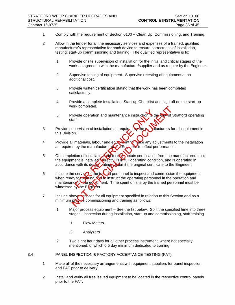
STRATFORD WPCP CLARIFIER UPGRADES AND Section 13100 STRUCTURAL REHABILITATION CONTROL & INSTRUMENTATION
Contract 16-9725 Page 36 of 45
.1 Comply with the requirement of Section 0100 – Clean Up, Commissioning, and Training.
.2 Allow in the tender for all the necessary services and expenses of a trained, qualified manufacturer’s representative for each device to ensure correctness of installation, testing, start-up commissioning and training. The qualified representative is to:
.1 Provide onsite supervision of installation for the initial and critical stages of the work as agreed to with the manufacturer/supplier and as require by the Engineer.
.2 Supervise testing of equipment. Supervise retesting of equipment at no additional cost.
.3 Provide written certification stating that the work has been completed satisfactorily.
.4 Provide a complete Installation, Start-up Checklist and sign off on the start-up work completed.
.5 Provide operation and maintenance instruction to the City of Stratford operating staff.
.3 Provide supervision of installation as required by the manufacturers for all equipment in this Division.
.4 Provide all materials, labour and equipment to make any adjustments to the installation as required by the manufacturer or the Engineer to effect performance.
.5 On completion of installation and testing, obtain certification from the manufacturers that the equipment is installed correctly, is in full operating condition, and is operating in accordance with its design rating. Submit the original certificate to the Engineer.
.6 Include the service of the trained personnel to inspect and commission the equipment when ready for starting and to instruct the operating personnel in the operation and maintenance of the equipment. Time spent on site by the trained personnel must be witnessed by the Engineer.
.7 Include above services for all equipment specified in relation to this Section and as a minimum provide commissioning and training as follows:
.1 Major process equipment – See the list below. Split the specified time into three stages: inspection during installation, start up and commissioning, staff training.
.1 Flow Meters.
.2 Analyzers
.2 Two eight hour days for all other process instrument, where not specially mentioned, of which 0.5 day minimum dedicated to training.
3.4 PANEL INSPECTION & FACTORY ACCEPTANCE TESTING (FAT)
.1 Make all of the necessary arrangements with equipment suppliers for panel inspection and FAT prior to delivery.
.2 Install and verify all free issued equipment to be located in the respective control panels prior to the FAT.
FOR REFERENCE O
NLY
NOT OFFIC
IAL B
ID D
OCUMENT

STRATFORD WPCP CLARIFIER UPGRADES AND Section 13100 STRUCTURAL REHABILITATION CONTROL & INSTRUMENTATION
Contract 16-9725 Page 37 of 45
.3 Schedule the FAT sessions with the Engineer a minimum of 10 working days in advance.
Allow enough time for thorough testing and corrections to take place. Provide written indication of the control panels to test as part of the FAT.
.4 A maximum of two free standing control panels shall be tested during a scheduled FAT.
.5 Panel inspection and FAT is to be performed in the presence and to the satisfaction of the Engineer, and is to include all devices necessary to simulate actual operating conditions.
.6 Configure the PLC with a suitable “dummy” or shell program, establish communication, temporarily wire digital inputs to test switches and digital outputs to indicating lights, analog inputs to 4-20mA generators and analog outputs to panel meters to demonstrate functionality of all hardware and software. Exercise the hardware (i.e. I/O, communications, panel mounted instruments, etc.) with appropriate software in place to demonstrate/monitor operation of all connected equipment and wiring.
.7 Configure and demonstrate all network connections to the respective control panels. Provide temporary network connections to “test devices” to demonstrate the operation of all PLC communications modules, including:
.1 Devicenet
.2 Controlnet
.3 Modbus IP
.8 Make the necessary corrections as indicated by the tests, or as directed by the Engineer. Shipment of equipment to site is contingent on the Engineer’s approval.
3.5 INSTALLING INSTRUMENTS
.1 Install, test, calibrate and commission instruments in accordance with this Specification, drawings for construction and any special details where they apply. Where installation details are not indicated, conform to the manufacturer’s instructions and/or API RP550 recommendations.
.2 Unless otherwise shown or specified, all required mounting hardware, enclosures, terminations, junction boxes, etc. are to be provided. Refer to the tender drawings and the manufacturer’s documentation to confirm the necessary hardware and construction for specific mounting assemblies where such details are not specified herein.
.3 Do not mount instruments on vibrating structures (e.g. handrails), or on piping or near equipment that induces vibration. Do not mount instruments below or directly adjacent to lines conveying corrosive chemicals or near sources of leakage or spillage.
.4 Prepare metal surfaces and paint supports or frames the same colour as the member the complete assembly is mounted on.
.5 Locate instruments and their associated sensors, local isolation valves, isolation switches and other related accessories so that they are readily accessible for operation, maintenance or removal. Ensure that instrument displays are properly oriented so as to be easily viewed. Unless otherwise shown or specified, mount instruments 1.4 m above finished floors, grade or platforms. Allow for cabinet floor-pad heights when locating panel instruments. Any instrument that is not easily accessible for operation or maintenance, or any indicator that is not easily and readily visible must be relocated as directed by the Engineer at no charge to the Contract.
FOR REFERENCE O
NLY
NOT OFFIC
IAL B
ID D
OCUMENT

STRATFORD WPCP CLARIFIER UPGRADES AND Section 13100 STRUCTURAL REHABILITATION CONTROL & INSTRUMENTATION
Contract 16-9725 Page 38 of 45
.6 When drilling or installing conduit entry points instruments, protect internally mounted
equipment from vibration, shock and metal filings. Conduit entries must maintain the equipment or panel EEMAC rating.
.7 Field measure lengths for transducer cables, and similar items prior to ordering. Mechanically protect cables and adequately secure in place without sagging.
.8 For location, power, mounting and other related details, refer to the manufacturer’s installation details and to the instrument and electrical drawings issued for construction.
.9 Provide isolation valves for all instruments.
.10 Protect all instruments with capillaries throughout their length without sagging, by using painted/galvanized angle iron and clips. Avoid sharp bends in capillary and coil any excess close to the sensor end. Protect the coiled capillary by clipping to a steel plate or other safe method.
.11 Sensing and sample lines are to be run in ½ inch stainless steel tubing with “Swagelok” compression type fittings.
.12 Electrically heat trace all instrument sensing and sample lines liable to freezing.
.13 Install process sample piping and sensing lines to avoid accumulation of vapour or gas (in liquid service) and of liquid or condensate (on vapour or gas service) as appropriate.
.14 Position instruments so that they do not block or obstruct walkways or access points and provide adequate space around installation for removal of covers, etc.
.15 Standard instrument process connections of ½” NPT female are to be provided (pressure gauges normally ½ inch NPT male).
.16 Instrument support brackets may not be welded to process piping or equipment, but should generally be pedestal or wall mounted.
.17 Run field cables for analog signals in separate conduit from 120VAC/24VDC control or 120VAC power supply cables.
.18 Use field junction boxes suitable for the area classification to “marshal” groups of signals of the same type in an area and cable back to buildings and local control panel with multicore cables.
.19 Junction boxes may be FRP (fibreglass reinforced plastic) or similar material suitable for the area and rust and weather resistant. Terminals inside field junction boxes are to be DIN rail mounted.
.20 Provide the necessary mechanical shields, mounting plates to properly secure and protect transducers. Provide stilling wells wherever turbulence can adversely affect measurement.
.21 Once an instrument has been inspected by the Engineer and initially calibrated, it is to remain powered up at all times unless servicing the instrument itself. Immediately install keepers on all panel circuit breakers powering instruments.
.22 Instrument calibration, setpoints and other programmable parameters are to be confirmed with the Engineer during on-site inspection as soon as site conditions are sufficiently ready. Final calibration values may and will be different than nominal values specified in the Product Data Sheet at no extra cost to the Contract.
FOR REFERENCE O
NLY
NOT OFFIC
IAL B
ID D
OCUMENT

STRATFORD WPCP CLARIFIER UPGRADES AND Section 13100 STRUCTURAL REHABILITATION CONTROL & INSTRUMENTATION
Contract 16-9725 Page 39 of 45
3.6 IDENTIFICATION AND TAGGING
.1 Identify systems and equipment in accordance with the provisions of this specification. Systems and equipment include:
.1 All items furnished under this contract.
.2 Items defined in this contract that require identification;
.1 Identification of wiring and electrical equipment as specified and tagged in the PLC I/O list.
.2 Provide a Tag text list to Engineer for approval prior manufacturing.
.3 Provide tags of the following materials:
.1 Field instrument tags are 10 gauge, stainless steel with black lettering.
.2 Equipment tags are 10 gauge, stainless steel with green lettering.
.3 Control panels tags are to be Lamicoid, black background with white lettering.
.4 Size tags as 100 x 40 with maximum three lines, front height as 6.5mm.
.5 Use text with the following characteristics:
.1 Lettering – Uppercase
.2 Font – Times New Roman
.3 Style – Regular
.4 Size – Maximum to fit label width, minimum 3mm
.5 Character spacing – Normal
.6 Justification – Center lettering on each line
.6 Submit with the Shop Drawings, a typed list indicating all nameplates wording as well as proposed types, sizes and styles.
.7 Prior to installation of new items, apply identification nameplates to each instrument, panel, telemetry device and controller. Where existing instruments are re-used, or connected into the new system/control panel, provide identification nameplates for these instruments also.
.8 Lamicoid nameplates shall be provided for each piece of instrumentation equipment. (For interior or exterior panel mounted equipment).
.9 Mount tags so that they are readily apparent and legible. Place tags within a height range of 1200mm to 1650mm if possible. Do not obscure or mount over other nameplates, labels or tags.
.10 Nameplates shall be fastened with corrosion resistant screws.
FOR REFERENCE O
NLY
NOT OFFIC
IAL B
ID D
OCUMENT

STRATFORD WPCP CLARIFIER UPGRADES AND Section 13100 STRUCTURAL REHABILITATION CONTROL & INSTRUMENTATION
Contract 16-9725 Page 40 of 45
.11 Nameplates on field equipment and external to control panels to be black
background with white lettering. Internal panel labels to be black background and white lettering.
.12 Identify transducer and miscellaneous hardware with stainless steel labels denoting tag name only, permanently fastened to either the transducer housing or cable.
.13 Wiring:
.1 Identify all PLC I/O signals on field terminal rails with appropriate tag.
.2 Identify all wiring at both ends with appropriate, permanent wire markers.
3.7 CONTROLLER APPLICATION PROGRAM INSTALLATION, TESTING & CONTROL SYSTEM COMMISSIONING
.1 When field pre-commissioning of the instrumentation and control system has been completed as specified above, the system is ready to load control application program.
.2 Coordinate all commissioning activities. Supply all labour and materials required to coordinate instrument and controls commissioning with other trades.
.3 Provide all labour and materials necessary to commission and operate the system for the duration of the run or period. During this time all equipment is expected to run in automatic mode.
.4 Perform the commissioning activities associated with operation of the treatment plant process equipment under control by the software program, as directed by the programmer.
.5 Take all necessary steps to ensure that all equipment or parts of the system successfully tested and deemed ready for their intended use stay in operation.
.6 Provide clear signs/marking as to required status on the equipment that is to remain powered up, left in Auto, or remain Off, etc., during the commissioning period. Agree with the Engineer on the method for achieving this and ensure safe and compliant operation of the equipment at all times.
.7 Adopt a recognized lock-out policy and agree to it with the Engineer. Coordinate the requirement for lock-out for safety reasons with the scheduled commissioning program so that all equipment needed to commission a process/area is available concurrently.
.8 Make minor corrections/additions to wiring, terminations, instrument calibrations and settings as normally expected necessary to resolve operational problems during commissioning at no additional cost.
3.8 SITE ACCEPTANCE TESTING (SAT)
.1 When initial site inspections and commissioning of the instrumentation and the control system is satisfactorily complete, schedule with the Engineer to demonstrate the entire system is ready to start control application program commissioning.
.2 Include for the presence of qualified instrument technicians and equipment manufacturer’s representatives to supervise the test if requested by the Engineer. Testing is to demonstrate the proper operation of all field physical input and output signals of the PLC system under actual operating conditions to the satisfaction of the
FOR REFERENCE O
NLY
NOT OFFIC
IAL B
ID D
OCUMENT

STRATFORD WPCP CLARIFIER UPGRADES AND Section 13100 STRUCTURAL REHABILITATION CONTROL & INSTRUMENTATION
Contract 16-9725 Page 41 of 45
Engineer. This includes proper operations between PLCs, and all peripheral devices. Supply all labour, instruments and materials to perform the testing.
.3 The SAT must be satisfactorily complete prior to applying for a Certificate of Substantial Performance.
.4 Deliver all testing software, panel keys etc. to the Engineer.
.5 Provide test programming to suit all PLC applications, and provide the same I/O and communications demonstration performed during the FAT.
3.9 TRAINING
.1 Comply with the requirements of Section 01820 – Demonstration and Commissioning.
.2 Supply a site training program for the plant operating personnel consisting of:
.1 Maintenance Training (16 hours) in two groups of eight hours each by Instrument Supplier and/or appropriate equipment manufacturer’s representatives.
.2 Operator training (16 hours) in two groups of eight hours each by Instrument Supplier.
.3 Dates personnel receiving training will be coordinated by the City of Stratford.
.4 The training program is to be conducted by qualified instrument technicians and competent manufacturer’s personnel experienced both with the product and with instruction, using system operation and maintenance manual data as the basis for demonstrations and instructions.
.5 Training shall take place at the site or at the equipment itself. Operation and maintenance manuals shall be submitted to the City of Stratford a minimum of 30 days prior to the training occurring.
.6 The training program is to include routine maintenance of the equipment.
.7 The site training program must be complete prior to application for a Certificate of Substantial Performance of the work.
.8 Pay all costs associated with the training program, with the sole exception of salaries associated with the operating personnel being trained.
3.10 PROCESS PERFORMANCE OPERATION
.1 Provide all labour and materials necessary to support the process and the instrumentation and control system for the duration of the contract performance run. During this operation all equipment is expected to run in automatic mode.
3.11 WARRANTY AND GUARANTEE PERIOD ACTIVITIES
.1 During the warranty period, hardware service should be provided by a factory trained service representative who shall be on-site within 24 hours of a service request, seven days/week, including weekends and holidays. The service representative shall be equipped with all necessary tools, testing equipment, spare parts, and expertise to perform the service in one visit.
.1 For each service call submit a report giving the following information:
FOR REFERENCE O
NLY
NOT OFFIC
IAL B
ID D
OCUMENT

STRATFORD WPCP CLARIFIER UPGRADES AND Section 13100 STRUCTURAL REHABILITATION CONTROL & INSTRUMENTATION
Contract 16-9725 Page 42 of 45
.1 Part numbers, description and prices for items replaced.
.2 Revised hard copy/soft copy listings of program changes.
.3 Hours worked by maintenance personnel.
.4 Reason for the service call, and whether preventative, unscheduled or corrective maintenance was carried out.
.5 Name of City of Stratford representative present during repairs. Explain the problem and solutions to the City of Stratford representatives.
.6 Description of problem as discovered on arrival at site and itemized report of activities performed to isolate and correct problem.
.7 Identification of any required actions to prevent similar future occurrence.
.8 Name of attending operations representative, time of call and time of arrival on site.
.2 A single contact point shall be provided for all hardware such that the City of Stratford representative need only call a single phone number irrespective of which piece of hardware has failed.
.3 Spare Components/Firmware & Software Upgrades:
.1 The supplier should have access to a dedicated spare parts inventory for each component provided. Parts shall be available within 24 hours of a service parts request, seven days/week.
.2 Include key spare parts that are not normally available immediately from stock, in the Recommended Spare Parts List.
3.12 INSTALLATION OF EQUIPMENT
.1 Provide all necessary labour, equipment, tools, anchor bolts, etc., for the complete installation of all equipment specified under this Division.
.2 Install all equipment in a workmanlike manner and in accordance with the manufacturer’s drawings, instructions and/or under the direction of his qualified technical representative unless otherwise specified or instructed by the Engineer.
.3 All communications equipment requiring fiber optic communications shall be verified by a light meter to demonstrate that the fiber optic media is correctly installed to suit the application.
.4 All fiber optic, serial and Ethernet connections shall be tested and verified operational.
.5 All communication cables, including serial, fiber optic and Ethernet shall be continuous, with no splices or junction points.
.6 Existing PLC automation, SCADA HMI’s and communications networks must remain in service for the duration of the contract. The Contractor must obtain written approval from the Engineer and owner prior to integrating the new I/O and communications links into the existing RPU control panels.
FOR REFERENCE O
NLY
NOT OFFIC
IAL B
ID D
OCUMENT

STRATFORD WPCP CLARIFIER UPGRADES AND Section 13100 STRUCTURAL REHABILITATION CONTROL & INSTRUMENTATION
Contract 16-9725 Page 43 of 45
.7 A representative from the Owner must be present during any interruption to the existing
PLC, RPU and/or SCADA networks to suit the RPU filter control panel retrofits. The Contractor shall coordinate the attendance of the Owners representatives.
3.13 DATA COMMUNICATIONS OUTLET INSTALLATION
.1 Install all Ethernet cable in accordance with manufacturer’s recommendations.
.2 Ethernet cable runs in control rooms, offices or other rooms with drywall shall be concealed behind the walls and terminate in a wall mounted jack.
.3 All other Ethernet cable runs shall be neatly dressed and terminated both ends with a flush or wall mounted jack.
.4 All outlets shall be installed in the following manner:
.1 Cables shall be coiled in the in-wall or surface-mount boxes if adequate space is present to house the cable coil without exceeding the manufacturer’s bend radius. In hollow wall installations where box eliminators are used, excess wire can be stored in the wall. No more than 300mm of slack shall be stored in an in-wall box, modular furniture raceway, or insulated walls. Excess slack may be neatly coiled and stored in the ceiling above each drop location when there is not enough space present in the outlet box to store slack cable.
.5 In addition, each cable type shall be terminated as indicated below:
.1 Cables shall be dressed and terminated in accordance with the recommendations made in the TIA/EIA-568-B document, manufacturer’s recommendations and/or best industry practices.
.2 Pair untwist at the termination shall not exceed one half an inch for Category 5e connecting hardware.
.3 Bend radius of the cable in the termination area shall not be less than four times the outside diameter of the cable.
.4 The cable jacket shall be maintained as close as possible to the termination point.
.5 Data jacks shall occupy the top positions on the faceplate. Data jacks in horizontally oriented faceplates shall occupy the left most positions.
3.14 NETWORK CONNECTIONS
.1 Configure all new and existing fibre patch panels, switches, media converters, PLC’s, TVSS’s, wall jacks, fibre patch cords, copper patch cords and other devices as required to provide a complete and functional communications systems as specified in this section.
3.15 LAN COMMISSIONING
.1 All IP addresses to be supplied by the Engineer.
.2 Install and connect new Ethernet cables as shown on the drawings..
.3 Configure, test and demonstrate to the Engineer the correct functioning of the PLC SCADA LAN by demonstrating communications between the each device and/or control
FOR REFERENCE O
NLY
NOT OFFIC
IAL B
ID D
OCUMENT

STRATFORD WPCP CLARIFIER UPGRADES AND Section 13100 STRUCTURAL REHABILITATION CONTROL & INSTRUMENTATION
Contract 16-9725 Page 44 of 45
panel connected to the LAN and a test device (i.e. a laptop provided by the Contractor and equipped with software to suit the communications demonstration).
3.16 DEVICENET CABLE INSTALLATION
.1 Total Device network current draw does not exceed power supply current limit.
.2 Common mode voltage drop does not exceed limit.
.3 Number of Devicenet nodes does not exceed 64 on one network. The practical limit on Devicenet nodes may be 61 devices since you should allow one node each for the scanner, the computer interface module, and an open node at node 63.
.4 No single drop over 6m.
.5 Cumulative drop line budget does not exceed network baud rate limit.
.6 Total network trunk length does not exceed the maximum allowable per the network data rate.
.7 Terminating resistors are on each end of the trunk line.
.8 Ground, at only one location in the center of the network.
.9 Use the following approved tap boxes to suit device drops from the main trunk line.
.1 2 – Port Devicenet tap Allen Bradley Mod 1485.P2T5-T5.
.2 4 – Port Devicenet tap Allen Bradley Mod 1485.P4T5-T5.
.3 Approved Brad Harrison Equal
.10 Install Devicenet network in accordance with Allen Bradley installation guide line cat No. DN-6.7.2.
3.17 SUPERVISION AND COMMISSIONING
.1 A supervision and commissioning period shall be allowed for by the Contractor for his supplier to thoroughly check the final installation and performance of each individual piece of equipment, to check each loop control, to start up the equipment and to instruct the Plant Operator on the operation and maintenance of the system. The work shall also include site supervision of the installations where necessary, repair and/or adjustments to the supplier's equipment, and co-ordinate the field supervision by other suppliers and the Contractor within their areas of responsibility.
.2 The start-up procedures will not be carried out without the co- operation and presence of the Engineer. The Contractor shall be responsible for co-ordinating the work, and for making his supplier available to completely commission the entire control and instrumentation system so that it is in perfect running order. The cost of this supervision and commissioning by the supplier for the Contractor shall be total included for in the Contractor's tender. No extra accommodation or meal expenses will be paid. The Contractor remains responsible for a complete and working system, in full accordance with these documents, and at the price bid in his tender.
.3 The Contractor shall obtain written approval from the Engineer, Owner, and Operator prior to modifying the existing system.
FOR REFERENCE O
NLY
NOT OFFIC
IAL B
ID D
OCUMENT

STRATFORD WPCP CLARIFIER UPGRADES AND Section 13100 STRUCTURAL REHABILITATION CONTROL & INSTRUMENTATION
Contract 16-9725 Page 45 of 45
.4 The commissioning will not be considered complete without a complete, final, and up-to-
date test software listing being supplied.
.5 Non-Operational Tests
.1 Verify and demonstrate the operation of all communications links including:
.1 Devicenet Communications links to all Devicenet type solid state protection devices located in the respective switchgear control panels, including soft starters and VFD’s.
.2 Ethernet communications links to all digital metering devices, and packaged PLC control systems.
.6 Operational Tests
.1 Demonstrate the operation of all communications systems.
.2 Demonstrate all remote I/O automation control functions.
.3 Demonstrate operations of each Devicenet capable equipment on the Devicenet network. Provide all required equipment including computers, software, and communications interface cards to suit demonstration of the Devicenet and Controlnet networks.
.7 The complete control system and instrumentation must be fully operational and without deviancies prior to implementation of the client supplied custom automation programming.
.8 The Contractor shall provide the services of the installing electrician, on site for a period of not less than 15 non-consecutive days to assist in the testing of the client supplied custom automation applications. Any changes or adjustments to field wiring, setpoints, and system operation shall be at no cost.
END OF SECTION FOR REFERENCE O
NLY
NOT OFFIC
IAL B
ID D
OCUMENT

FOR REFERENCE O
NLY
NOT OFFIC
IAL B
ID D
OCUMENT

REGIONAL MUNICIPALITY OF PEEL NORTH BRAMPTON PUMPING STATION (WPS-ICP-01) I/O List
REVISION 1.0, 06/05/2016Ref # Tag PANEL RACK SLOT
CHAN./P
OINTDESCRIPTION TYPE
SIGNAL
TYPEPOWER Comments
1 ICP-B 0 3 1 OCCUPIED DI 24VDC
2 ICP-B 0 3 2 OCCUPIED DI 24VDC
3 ICP-B 0 3 3 OCCUPIED DI 24VDC
4 ICP-B 0 3 4 OCCUPIED DI 24VDC
5 ICP-B 0 3 5 SPARE DI 24VDC
6 ICP-B 0 3 6 SPARE DI 24VDC
7 ICP-B 0 3 7 OCCUPIED DI 24VDC
8 ICP-B 0 3 8 OCCUPIED DI 24VDC
9 ICP-B 0 3 9 OCCUPIED DI 24VDC
10 ICP-B 0 3 10 OCCUPIED DI 24VDC
11 ICP-B 0 3 11 SPARE DI 24VDC
12 ICP-B 0 3 12 SPARE DI 24VDC
13 ICP-B 0 3 13 SPARE DI 24VDC
14 ICP-B 0 3 14 SPARE DI 24VDC
15 ICP-B 0 3 15 SPARE DI 24VDC
16 ICP-B 0 3 16 SPARE DI 24VDC
17 ICP-B 0 3 17 SPARE DI 24VDC
18 ICP-B 0 4 1 OCCUPIED AI 4-20mA
19 ICP-B 0 4 2 OCCUPIED AI 4-20mA
20 ICP-B 0 4 3 OCCUPIED AI 4-20mA
21 ICP-B 0 4 4 OCCUPIED AI 4-20mA
22 ICP-B 0 5 1 OCCUPIED AI 4-20mA
23 ICP-B 0 5 2 OCCUPIED AI 4-20mA
24 ICP-B 0 5 3 OCCUPIED AI 4-20mA
25 ICP-B 0 5 4 OCCUPIED AI 4-20mA
26 ICP-B 0 6 1 OCCUPIED AI 4-20mA
27 ICP-B 0 6 2 OCCUPIED AI 4-20mA
28 LIT201A_LI ICP-B 0 6 3 Primary Clarifier Valve Chamber 'A' Level Indication AI 4-20mA New I/O
29 LIT201B_LI ICP-B 0 6 4 Primary Clarifier Valve Chamber 'B' Level Indication AI 4-20mA New I/O
30 ICP-B 0 7 1 OCCUPIED AI 4-20mA
31 ICP-B 0 7 2 OCCUPIED AI 4-20mA
32 ICP-B 0 7 3 OCCUPIED AI 4-20mA
33 ICP-B 0 7 4 OCCUPIED AI 4-20mA
34 ICP-B 0 8 1 OCCUPIED AI 4-20mA
35 ICP-B 0 8 2 OCCUPIED AI 4-20mA
36 ICP-B 0 8 3 OCCUPIED AI 4-20mA
37 LIT131_LI ICP-B 0 8 4 Distribution Chamber Level Indication AI 4-20mA New I/O
38 PC131_XA ICP-B 0 9 1 Primary Clarifier #1 Pump Run Status DI 24VDC New I/O; New Card
39 PC131_MN ICP-B 0 9 2 Primary Clarifier #1 General Alarm DI 24VDC New I/O; New Card
40 PC132_XA ICP-B 0 9 3 Primary Clarifier #2 Pump Run Status DI 24VDC New I/O; New Card
41 PC132_MN ICP-B 0 9 4 Primary Clarifier #2 General Alarm DI 24VDC New I/O; New Card
42 PC133_XA ICP-B 0 9 5 Primary Clarifier #3 Pump Run Status DI 24VDC New I/O; New Card
43 PC133_MN ICP-B 0 9 6 Primary Clarifier #3 General Alarm DI 24VDC New I/O; New Card
44 PC134_XA ICP-B 0 9 7 Primary Clarifier #4 Pump Run Status DI 24VDC New I/O; New Card
45 PC134_MN ICP-B 0 9 8 Primary Clarifier #4 General Alarm DI 24VDC New I/O; New Card
46 IG131_YN ICP-B 0 9 9 Inlet Slide Gate #1 Control Mode DI 24VDC New I/O; New Card
47 IG131_ZH ICP-B 0 9 10 Inlet Slide Gate #1 Open Indication DI 24VDC New I/O; New Card
48 IG131_ZL ICP-B 0 9 11 Inlet Slide Gate #1 Close Indication DI 24VDC New I/O; New Card
49 IG132_YN ICP-B 0 9 12 Inlet Slide Gate #2 Control Mode DI 24VDC New I/O; New Card
50 IG132_ZH ICP-B 0 9 13 Inlet Slide Gate #2 Open Indication DI 24VDC New I/O; New Card
51 IG132_ZL ICP-B 0 9 14 Inlet Slide Gate #2 Close Indication DI 24VDC New I/O; New Card
52 LIT131_XA ICP-B 0 9 15 Distribution Chamber Loss of Echo DI 24VDC New I/O; New Card
53 LIT201A_XA ICP-B 0 9 16 Primary Clarifier Valve Chamber "A" Loss of Echo DI 24VDC New I/O; New Card
54 LIT201B_XA ICP-B 0 10 1 Primary Clarifier Valve Chamber "B" Loss of Echo DI 24VDC New I/O; New Card
55 IG133_YN ICP-B 0 10 2 Inlet Slide Gate #3 Control Mode DI 24VDC New I/O; New Card
56 IG133_ZH ICP-B 0 10 3 Inlet Slide Gate #3 Open Indication DI 24VDC New I/O; New Card
57 IG133_ZL ICP-B 0 10 4 Inlet Slide Gate #3 Close Indication DI 24VDC New I/O; New Card
58 IG134_YN ICP-B 0 10 5 Inlet Slide Gate #4 Control Mode DI 24VDC New I/O; New Card
59 IG134_ZH ICP-B 0 10 6 Inlet Slide Gate #4 Open Indication DI 24VDC New I/O; New Card
60 IG134_ZL ICP-B 0 10 7 Inlet Slide Gate #4 Close Indication DI 24VDC New I/O; New Card
61 MV201A_YN ICP-B 0 10 8 Motorized Valve Control Mode DI 24VDC New I/O; New Card
62 MV201A_ZH ICP-B 0 10 9 Motorized Valve Open Indication DI 24VDC New I/O; New Card
63 MV201A_ZL ICP-B 0 10 10 Motorized Valve Close Indication DI 24VDC New I/O; New Card
64 MV202A_YN ICP-B 0 10 11 Motorized Valve Control Mode DI 24VDC New I/O; New Card
65 MV202A_ZH ICP-B 0 10 12 Motorized Valve Open Indication DI 24VDC New I/O; New Card
66 MV202A_ZL ICP-B 0 10 13 Motorized Valve Close Indication DI 24VDC New I/O; New Card
67 MV203A_YN ICP-B 0 10 14 Motorized Valve Control Mode DI 24VDC New I/O; New Card
68 MV203A_ZH ICP-B 0 10 15 Motorized Valve Open Indication DI 24VDC New I/O; New Card
69 MV203A_ZL ICP-B 0 10 16 Motorized Valve Close Indication DI 24VDC New I/O; New Card
70 ICP-B 1 1 1 OCCUPIED DO 24VDC
Appendix - I/O List, Stratford WPCP ICPB Proposed IO
Last Printed: 06/05/2016, 10:48 AM Page 1 of 4
FOR REFERENCE O
NLY
NOT OFFIC
IAL B
ID D
OCUMENT

REGIONAL MUNICIPALITY OF PEEL NORTH BRAMPTON PUMPING STATION (WPS-ICP-01) I/O List
REVISION 1.0, 06/05/2016Ref # Tag PANEL RACK SLOTCHAN./P
OINTDESCRIPTION TYPE
SIGNAL
TYPEPOWER Comments
71 ICP-B 1 1 2 OCCUPIED DO 24VDC
72 ICP-B 1 1 3 OCCUPIED DO 24VDC
73 ICP-B 1 1 4 OCCUPIED DO 24VDC
74 ICP-B 1 1 5 OCCUPIED DO 24VDC
75 ICP-B 1 1 6 OCCUPIED DO 24VDC
76 ICP-B 1 1 7 SPARE DO 24VDC
77 ICP-B 1 1 8 OCCUPIED DO 24VDC
78 ICP-B 1 2 1 OCCUPIED DO 24VDC
79 ICP-B 1 2 2 OCCUPIED DO 24VDC
80 ICP-B 1 2 3 OCCUPIED DO 24VDC
81 ICP-B 1 2 4 OCCUPIED DO 24VDC
82 ICP-B 1 2 5 OCCUPIED DO 24VDC
83 ICP-B 1 2 6 OCCUPIED DO 24VDC
84 ICP-B 1 2 7 SPARE DO 24VDC
85 ICP-B 1 2 8 SPARE DO 24VDC
86 IG131_VH ICP-B 1 3 1 Inlet Slide Gate #1 Open Command DO 24VDC New I/O; New Card
87 IG131_VL ICP-B 1 3 2 Inlet Slide Gate #1 Close Command DO 24VDC New I/O; New Card
88 IG132_VH ICP-B 1 3 3 Inlet Slide Gate #2 Open Command DO 24VDC New I/O; New Card
89 IG132_VL ICP-B 1 3 4 Inlet Slide Gate #2 Close Command DO 24VDC New I/O; New Card
90 IG133_VH ICP-B 1 3 5 Inlet Slide Gate #3 Open Command DO 24VDC New I/O; New Card
91 IG133_VL ICP-B 1 3 6 Inlet Slide Gate #3 Close Command DO 24VDC New I/O; New Card
92 IG134_VH ICP-B 1 3 7 Inlet Slide Gate #4 Open Command DO 24VDC New I/O; New Card
93 IG134_VL ICP-B 1 3 8 Inlet Slide Gate #4 Close Command DO 24VDC New I/O; New Card
94 MV201A_VH ICP-B 1 4 1 Motorized Valve Open Command DO 24VDC New I/O; New Card
95 MV201A_VL ICP-B 1 4 2 Motorized Valve Close Command DO 24VDC New I/O; New Card
96 MV202A_VH ICP-B 1 4 3 Motorized Valve Open Command DO 24VDC New I/O; New Card
97 MV202A_VL ICP-B 1 4 4 Motorized Valve Close Command DO 24VDC New I/O; New Card
98 MV203A_VH ICP-B 1 4 5 Motorized Valve Open Command DO 24VDC New I/O; New Card
99 MV203A_VL ICP-B 1 4 6 Motorized Valve Close Command DO 24VDC New I/O; New Card
100 MV204A_VH ICP-B 1 4 7 Motorized Valve Open Command DO 24VDC New I/O; New Card
101 MV204A_VL ICP-B 1 4 8 Motorized Valve Close Command DO 24VDC New I/O; New Card
102 MV205A_VH ICP-B 1 5 1 Motorized Valve Open Command DO 24VDC New I/O; New Card
103 MV205A_VL ICP-B 1 5 2 Motorized Valve Close Command DO 24VDC New I/O; New Card
104 MV201B_VH ICP-B 1 5 3 Motorized Valve Open Command DO 24VDC New I/O; New Card
105 MV201B_VL ICP-B 1 5 4 Motorized Valve Close Command DO 24VDC New I/O; New Card
106 MV202B_VH ICP-B 1 5 5 Motorized Valve Open Command DO 24VDC New I/O; New Card
107 MV202B_VL ICP-B 1 5 6 Motorized Valve Close Command DO 24VDC New I/O; New Card
108 MV203B_VH ICP-B 1 5 7 Motorized Valve Open Command DO 24VDC New I/O; New Card
109 MV203B_VL ICP-B 1 5 8 Motorized Valve Close Command DO 24VDC New I/O; New Card
110 MV204B_VH ICP-B 1 6 1 Motorized Valve Open Command DO 24VDC New I/O; New Card
111 MV204B_VL ICP-B 1 6 2 Motorized Valve Close Command DO 24VDC New I/O; New Card
112 MV205B_VH ICP-B 1 6 3 Motorized Valve Open Command DO 24VDC New I/O; New Card
113 MV205B_VL ICP-B 1 6 4 Motorized Valve Close Command DO 24VDC New I/O; New Card
114 ICP-B 1 6 5 SPARE DO 24VDC Spare; New Card
115 ICP-B 1 6 6 SPARE DO 24VDC Spare; New Card
116 ICP-B 1 6 7 SPARE DO 24VDC Spare; New Card
117 ICP-B 1 6 8 SPARE DO 24VDC Spare; New Card
118 ICP-B 1 7 - SPARE SLOT
119 ICP-B 1 8 1 OCCUPIED AI 4-20mA
120 ICP-B 1 8 2 OCCUPIED AI 4-20mA
121 ICP-B 1 8 3 OCCUPIED AI 4-20mA
122 ICP-B 1 8 4 SPARE AI 4-20mA
123 ICP-B 1 9 1 OCCUPIED AO 4-20mA
124 ICP-B 1 9 2 OCCUPIED AO 4-20mA
125 ICP-B 1 10 1 OCCUPIED AO 4-20mA
126 ICP-B 1 10 2 OCCUPIED AO 4-20mA
127 ICP-B 2 1 1 OCCUPIED DI 24VDC
128 ICP-B 2 1 2 OCCUPIED DI 24VDC
129 ICP-B 2 1 3 OCCUPIED DI 24VDC
130 ICP-B 2 1 4 OCCUPIED DI 24VDC
131 ICP-B 2 1 5 OCCUPIED DI 24VDC
132 ICP-B 2 1 6 OCCUPIED DI 24VDC
133 ICP-B 2 1 7 OCCUPIED DI 24VDC
134 ICP-B 2 1 8 OCCUPIED DI 24VDC
135 ICP-B 2 1 9 OCCUPIED DI 24VDC
136 ICP-B 2 1 10 SPARE DI 24VDC
137 ICP-B 2 1 11 SPARE DI 24VDC
138 ICP-B 2 1 12 SPARE DI 24VDC
139 ICP-B 2 1 13 SPARE DI 24VDC
140 ICP-B 2 1 14 SPARE DI 24VDC
141 ICP-B 2 1 15 SPARE DI 24VDC
Appendix - I/O List, Stratford WPCP ICPB Proposed IO
Last Printed: 06/05/2016, 10:48 AM Page 2 of 4
FOR REFERENCE O
NLY
NOT OFFIC
IAL B
ID D
OCUMENT

REGIONAL MUNICIPALITY OF PEEL NORTH BRAMPTON PUMPING STATION (WPS-ICP-01) I/O List
REVISION 1.0, 06/05/2016Ref # Tag PANEL RACK SLOTCHAN./P
OINTDESCRIPTION TYPE
SIGNAL
TYPEPOWER Comments
142 ICP-B 2 1 16 SPARE DI 24VDC
143 ICP-B 2 2 1 OCCUPIED DI 24VDC
144 ICP-B 2 2 2 OCCUPIED DI 24VDC
145 ICP-B 2 2 3 OCCUPIED DI 24VDC
146 ICP-B 2 2 4 SPARE DI 24VDC
147 ICP-B 2 2 5 OCCUPIED DI 24VDC
148 ICP-B 2 2 6 OCCUPIED DI 24VDC
149 ICP-B 2 2 7 OCCUPIED DI 24VDC
150 ICP-B 2 2 8 OCCUPIED DI 24VDC
151 ICP-B 2 2 9 OCCUPIED DI 24VDC
152 ICP-B 2 2 10 OCCUPIED DI 24VDC
153 ICP-B 2 2 11 OCCUPIED DI 24VDC
154 ICP-B 2 2 12 OCCUPIED DI 24VDC
155 ICP-B 2 2 13 SPARE DI 24VDC
156 ICP-B 2 2 14 OCCUPIED DI 24VDC
157 ICP-B 2 2 15 SPARE DI 24VDC
158 ICP-B 2 2 16 SPARE DI 24VDC
159 ICP-B 2 3 1 OCCUPIED DI 24VDC
160 ICP-B 2 3 2 OCCUPIED DI 24VDC
161 ICP-B 2 3 3 OCCUPIED DI 24VDC
162 ICP-B 2 3 4 OCCUPIED DI 24VDC
163 ICP-B 2 3 5 OCCUPIED DI 24VDC
164 ICP-B 2 3 6 OCCUPIED DI 24VDC
165 ICP-B 2 3 7 OCCUPIED DI 24VDC
166 ICP-B 2 3 8 OCCUPIED DI 24VDC
167 ICP-B 2 3 9 OCCUPIED DI 24VDC
168 ICP-B 2 3 10 OCCUPIED DI 24VDC
169 ICP-B 2 3 11 OCCUPIED DI 24VDC
170 ICP-B 2 3 12 OCCUPIED DI 24VDC
171 ICP-B 2 3 13 SPARE DI 24VDC
172 ICP-B 2 3 14 SPARE DI 24VDC
173 ICP-B 2 3 15 SPARE DI 24VDC
174 ICP-B 2 3 16 SPARE DI 24VDC
175 ICP-B 2 4 1 OCCUPIED DI 24VDC
176 ICP-B 2 4 2 OCCUPIED DI 24VDC
177 ICP-B 2 4 3 OCCUPIED DI 24VDC
178 ICP-B 2 4 4 OCCUPIED DI 24VDC
179 ICP-B 2 4 5 OCCUPIED DI 24VDC
180 ICP-B 2 4 6 OCCUPIED DI 24VDC
181 ICP-B 2 4 7 OCCUPIED DI 24VDC
182 ICP-B 2 4 8 OCCUPIED DI 24VDC
183 ICP-B 2 4 9 OCCUPIED DI 24VDC
184 ICP-B 2 4 10 OCCUPIED DI 24VDC
185 ICP-B 2 4 11 OCCUPIED DI 24VDC
186 ICP-B 2 4 12 OCCUPIED DI 24VDC
187 ICP-B 2 4 13 SPARE DI 24VDC
188 ICP-B 2 4 14 SPARE DI 24VDC
189 ICP-B 2 4 15 SPARE DI 24VDC
190 ICP-B 2 4 16 SPARE DI 24VDC
191 ICP-B 2 5 1 OCCUPIED DI 24VDC
192 ICP-B 2 5 2 OCCUPIED DI 24VDC
193 ICP-B 2 5 3 OCCUPIED DI 24VDC
194 ICP-B 2 5 4 OCCUPIED DI 24VDC
195 ICP-B 2 5 5 OCCUPIED DI 24VDC
196 ICP-B 2 5 6 OCCUPIED DI 24VDC
197 ICP-B 2 5 7 OCCUPIED DI 24VDC
198 ICP-B 2 5 8 OCCUPIED DI 24VDC
199 ICP-B 2 5 9 OCCUPIED DI 24VDC
200 ICP-B 2 5 10 OCCUPIED DI 24VDC
201 ICP-B 2 5 11 OCCUPIED DI 24VDC
202 ICP-B 2 5 12 OCCUPIED DI 24VDC
203 ICP-B 2 5 13 SPARE DI 24VDC
204 ICP-B 2 5 14 SPARE DI 24VDC
205 ICP-B 2 5 15 SPARE DI 24VDC
206 ICP-B 2 5 16 SPARE DI 24VDC
207 MV204A_YN ICP-B 2 6 1 Motorized Valve Control Mode DI 24VDC New I/O; New Card
208 MV204A_ZH ICP-B 2 6 2 Motorized Valve Open Indication DI 24VDC New I/O; New Card
209 MV204A_ZL ICP-B 2 6 3 Motorized Valve Close Indication DI 24VDC New I/O; New Card
210 MV205A_YN ICP-B 2 6 4 Motorized Valve Control Mode DI 24VDC New I/O; New Card
211 MV205A_ZH ICP-B 2 6 5 Motorized Valve Open Indication DI 24VDC New I/O; New Card
212 MV205A_ZL ICP-B 2 6 6 Motorized Valve Close Indication DI 24VDC New I/O; New Card
Appendix - I/O List, Stratford WPCP ICPB Proposed IO
Last Printed: 06/05/2016, 10:48 AM Page 3 of 4
FOR REFERENCE O
NLY
NOT OFFIC
IAL B
ID D
OCUMENT

REGIONAL MUNICIPALITY OF PEEL NORTH BRAMPTON PUMPING STATION (WPS-ICP-01) I/O List
REVISION 1.0, 06/05/2016Ref # Tag PANEL RACK SLOTCHAN./P
OINTDESCRIPTION TYPE
SIGNAL
TYPEPOWER Comments
213 MV201B_YN ICP-B 2 6 7 Motorized Valve Control Mode DI 24VDC New I/O; New Card
214 MV201B_ZH ICP-B 2 6 8 Motorized Valve Open Indication DI 24VDC New I/O; New Card
215 MV201B_ZL ICP-B 2 6 9 Motorized Valve Close Indication DI 24VDC New I/O; New Card
216 MV202B_YN ICP-B 2 6 10 Motorized Valve Control Mode DI 24VDC New I/O; New Card
217 MV202B_ZH ICP-B 2 6 11 Motorized Valve Open Indication DI 24VDC New I/O; New Card
218 MV202B_ZL ICP-B 2 6 12 Motorized Valve Close Indication DI 24VDC New I/O; New Card
219 MV203B_YN ICP-B 2 6 13 Motorized Valve Control Mode DI 24VDC New I/O; New Card
220 MV203B_ZH ICP-B 2 6 14 Motorized Valve Open Indication DI 24VDC New I/O; New Card
221 MV203B_ZL ICP-B 2 6 15 Motorized Valve Close Indication DI 24VDC New I/O; New Card
222 MV204B_YN ICP-B 2 6 16 Motorized Valve Control Mode DI 24VDC New I/O; New Card
223 MV204B_ZH ICP-B 2 7 1 Motorized Valve Open Indication DI 24VDC New I/O; New Card
224 MV204B_ZL ICP-B 2 7 2 Motorized Valve Close Indication DI 24VDC New I/O; New Card
225 MV205B_YN ICP-B 2 7 3 Motorized Valve Control Mode DI 24VDC New I/O; New Card
226 MV205B_ZH ICP-B 2 7 4 Motorized Valve Open Indication DI 24VDC New I/O; New Card
227 MV205B_ZL ICP-B 2 7 5 Motorized Valve Close Indication DI 24VDC New I/O; New Card
228 ICP-B 2 7 6 SPARE DI 24VDC Spare; New Card
229 ICP-B 2 7 7 SPARE DI 24VDC Spare; New Card
230 ICP-B 2 7 8 SPARE DI 24VDC Spare; New Card
231 ICP-B 2 7 9 SPARE DI 24VDC Spare; New Card
232 ICP-B 2 7 10 SPARE DI 24VDC Spare; New Card
233 ICP-B 2 7 11 SPARE DI 24VDC Spare; New Card
234 ICP-B 2 7 12 SPARE DI 24VDC Spare; New Card
235 ICP-B 2 7 13 SPARE DI 24VDC Spare; New Card
236 ICP-B 2 7 14 SPARE DI 24VDC Spare; New Card
237 ICP-B 2 7 15 SPARE DI 24VDC Spare; New Card
238 ICP-B 2 7 16 SPARE DI 24VDC Spare; New Card
239 ICP-B 2 8 1 OCCUPIED AI 4-20mA
240 ICP-B 2 8 2 OCCUPIED AI 4-20mA
241 ICP-B 2 8 3 OCCUPIED AI 4-20mA
242 ICP-B 2 8 4 SPARE AI 4-20mA
243 ICP-B 2 9 1 OCCUPIED AO 4-20mA
244 ICP-B 2 9 2 OCCUPIED AO 4-20mA
245 ICP-B 2 10 1 OCCUPIED AO 4-20mA
246 ICP-B 2 10 2 OCCUPIED AO 4-20mA
Appendix - I/O List, Stratford WPCP ICPB Proposed IO
Last Printed: 06/05/2016, 10:48 AM Page 4 of 4
FOR REFERENCE O
NLY
NOT OFFIC
IAL B
ID D
OCUMENT

STRATFORD WPCP CLARIFIER UPGRADES AND Section 13110 STRUCTURAL REHABILITATION SCADA INTEGRATION SERVICES
Contract 16-9725 Page 1 of 9
1 GENERAL
1.1 RELATED SECTIONS
.1 Section 13100 – Control & Instrumentation
1.2 INTENT
.1 All work described in this section shall be performed by the Control System Integrator/Programmer (CSIP).
.2 It is the intent of this section to modify the existing control system (i.e. SCADA) for the Stratford WPCP to monitor and control process parameters and equipment to be supplied and installed under this contract, as shown on the drawings or specified.
.3 The SCADA system shall be complete, fully functional system and designed and developed to meet the control requirements of the process design indicated on the contract drawings.
1.3 DESCRIPTION
.1 The CSIP shall coordinate, develop and implement all system parameters, data tables and programs within the SCADA system to make the SCADA function as intended and to suit the process and automation objectives outlined in the Process Control Narrative and the contract documents.
.2 The CSIP is required to develop a detailed Automation System Control Narrative (ASCN), based on the process performance requirements outlined in the Process Control Narrative. The ASCN is to include but not be limited to the following information:
.1 Describe each process to be monitored and/or controlled by the plant automation system
.2 Provide a tag database for all real and virtual signals that will be included in the automation system. Identify the mode/type/units/range for each real or virtual signal.
.3 Identify all packaged automation systems to be integrated into the main plant HMI/SCADA application as required. Produce custom graphical HMI applications to match the full functionality of the status/control/alarm features provided by the respective package vendor OIT applications as required.
.4 Identify detailed control logic required in the operation of each process including, interlock logic, delay logic, adjustable variables, high/low limits, modes of operation, failure modes, and base conditions
.3 The CSIP shall coordinate and implement the necessary configurations in the SCADA system to integrate and interface the SCADA system with the control systems provided by the suppliers of packaged equipment.
.4 Develop a work plan with an itemized list of all deliverables.
.5 SCADA tag name assignments will developed and confirmed during the integration meeting process.
.6 The CSIP, the CSS and the Contractor shall provide all labour, supervision, tools, equipment, materials, services and miscellaneous expenses necessary to complete the work as outlined in this Section. The word “provide” shall be defined to mean supply, install, start up, test and commission.
.7 The Contractor shall obtain written approval from the Owner, Operator and the Engineer prior to implementing any modifications and/or interruptions to the existing Stratford WPCP operations.
FOR REFERENCE O
NLY
NOT OFFIC
IAL B
ID D
OCUMENT

STRATFORD WPCP CLARIFIER UPGRADES AND Section 13110 STRUCTURAL REHABILITATION SCADA INTEGRATION SERVICES
Contract 16-9725 Page 2 of 9
.8 The CSIP shall provide the software, programs, parameter and hardware settings as
required to integrate the new I/O described in section 13100 appendix A1 to the plant SCADA system. The new input & output (I/Os) will be monitored at existing Chemical Building control panel, ICP-B.
.9 The CSIP/Contractor shall modify the existing SCADA system HMI to incorporate new I/Os.
.1 Prior to construction, the Contractor/CSIP shall confirm the HMI computer specifications and obtain information on the HMI software version presently being used at the plant.
.2 Two (2) HMI client nodes shall be updated under this project. The two nodes are administration building lab room HMI and lunch room HMI.
1.4 STANDARDS
.1 Equipment furnished under this section shall be designed, constructed, and tested in accordance with the latest edition and requirements of the followings:
.1 Canadian Standards Association (CSA)
.2 Canadian Electrical Manufacturers Association (CEMA)
.3 National Electrical Manufacturers Association (NEMA), and NEMA ICS-1-109.60
.4 International Society for Measurement and Control
.5 The Instrumentation, Systems, and Automation Society (ISA)
.6 FCC Part 15 – Class A / Canadian’s Interference-Causing Equipment Standards (ICESs)
.7 Institute of Electrical and Electronics Engineers IEEE-519
.8 ANSI C37.90.
1.5 SUBMITTALS
.1 Conform with requirements of Division 1, including Sections 01330.
.2 Provide a new SCADA communications architecture schematic as required.
.3 A detailed submittal package as per section 13100.
1.6 OPERATION AND MAINTENANCE MANUALS
.1 Provide as per section 13100.
1.7 WORK INCLUDED
.1 The Control System Integrator/Programmer (CSIP) shall be responsible for:
.1 Coordinating with the CSS and executing the verification of the SCADA system including all PLC control panels, communication panels, and associated communication links provided as part of this project.
.2 Providing and implementing test PLC programming to verify and demonstrate that all new I/O cards are capable of monitoring all inputs and control of all outputs. Test programming shall demonstrate that all communications links operate as required.
.3 Providing and implementing a test OIT procedure or application to demonstrate and verify that the respective points in the PLC data table are correctly configured and operating. The OIT test application shall display the status of all
FOR REFERENCE O
NLY
NOT OFFIC
IAL B
ID D
OCUMENT

STRATFORD WPCP CLARIFIER UPGRADES AND Section 13110 STRUCTURAL REHABILITATION SCADA INTEGRATION SERVICES
Contract 16-9725 Page 3 of 9
I/O and include the ability to toggle discrete outputs and to adjust analogue input words between 0 to 100% to facilitate the verification of analogue outputs.
.4 Demonstrating the operation of the SCADA system and placing into service all SCADA equipment to the satisfaction of the Engineer.
.5 Integrate the process equipment packaged automation systems into the main SCADA HMI application. Reproduce all control/status/alarm/historical features that included the package system OIT applications into the main plant SCADA HMI application. Detailed HMI application graphics to be reviewed during the integration meeting process
.6 Incorporating new I/Os detailed in section 13100 appendix A1 into the existing plant SCADA system.
.7 Provide a controls description for the process control logic, based on the Process Control Narrative.
.8 Development of the custom graphical user interface application for the purpose of control and monitoring of the treatment plant process.
.9 Development of the user programs in the new PLC systems.
.10 Development of custom reports in accordance with the MOE compliance requirements for reporting.
.11 Development of a custom remote alarming application to suit the specific requirements of new treatment process systems.
.12 Development of SCADA system to provide daily reports, trends, alarm functions, historic data collection, and the associated displays, etc.
.13 Setting up and configuration of the new SCADA HMI/Servers in the control room of the Headworks building.
.14 Providing a manual that fully documents the operation, features and functions of the SCADA system.
.15 Demonstrating the complete specified functionality of the SCADA system to show compliance with these specifications through Factory and Site Acceptance Testing (FAT and SAT).
.16 Providing training/familiarization courses in the operation, trouble-shooting, and maintenance of the complete SCADA system. Training to take place at Petrolia WWTP or another location specified by Town of Petrolia.
.17 Providing support to the Engineer and Contractor during site acceptance testing (SAT).
.18 Assisting with the start-up & commissioning of all PLC/SCADA controlled equipment, including those in vendor supplied packages.
.19 Providing documentation, custom PLC programming and SCADA HMI integration in accordance with the Town of Petrolia requirements.
.20 Prepare detailed control narrative based on process narrative.
FOR REFERENCE O
NLY
NOT OFFIC
IAL B
ID D
OCUMENT

STRATFORD WPCP CLARIFIER UPGRADES AND Section 13110 STRUCTURAL REHABILITATION SCADA INTEGRATION SERVICES
Contract 16-9725 Page 4 of 9
.21 Verification of all I/O on site.
.22 Assist with start-up & commissioning of all PLC/SCADA controlled equipment.
.23 PLC/SCADA Programming documentation
.24 PLC/SCADA Manual
.25 PLC/SCADA Training – on site
.2 Programming
.1 The CSIP shall be responsible for programming for the new process system PLCs, database creations, and generation of all graphic display screens, alarm configurations, instantaneous trend, historical trends and reporting for the SCADA HMI computer stations at the Petrolia Wastewater Treatment Plant.
.2 The CSIP shall be responsible for configuration of all PLC I/O configuration,
scaling, and data exchange between the new PLCs and the PLC’s supplied within packaged equipment.
.3 The graphic display screens for the new process systems shall confirm with
configuration of the overall wastewater treatment plant control system workstations, with respect to colour usage conventions, general formatting and screen navigation.
.4 The CSIP configuration engineer shall meet with the Engineer, Owner and
Operations Staff to review the overall plant control system display configurations as per the integration meeting requirements described in this specification.
.3 Process Data Gap Recovery
.1 The CSIP shall provide a custom PLC programming and MS SQL application to provide data gap recovery of process signals that are trended by the SCADA HMI application that is interrupted due to a failure of the SCADA HMI I/O server or the Ethernet SCADA Network.
.2 Recover data is to be stored in the PLC process on board memory, based on a
rolling window to allow for data gap recovery of up to a 7 day failure of the SCADA HMI I/O server or the Ethernet Network.
.3 The recovery data is to be synchronised with the SCADA HMI, MS SQL historical
database such that all data gaps are continuously corrected.
.4 Integration Meetings
.1 A total of three integration meetings shall be held to suit the custom development of the PLC programming and SCADA HMI development.
.2 The meetings are to be hosted by the CSIP and must be located at the Stratford WPCP or a location selected by the client. The CSIP shall provide meeting facilities to accommodate all the CSIP personnel required to suit the PLC Programming, SCADA HMI development and 8 representatives from the Engineer/Owner. The CSIP shall equip the meeting faculties with visual aids, video monitors, and projectors as required to suit the presentation of the custom SCADA HMI applications.
FOR REFERENCE O
NLY
NOT OFFIC
IAL B
ID D
OCUMENT

STRATFORD WPCP CLARIFIER UPGRADES AND Section 13110 STRUCTURAL REHABILITATION SCADA INTEGRATION SERVICES
Contract 16-9725 Page 5 of 9
.3 Prior to the first integration meeting, the CSIP is required to submit the following
documentation:
.1 Modified ICP-B PLC architecture schematic. (produced by the Control System Supplier – CSS).
.2 Equipment submittals for PLC’s, SCADA HMI Computers and Work Stations, communications modules (Produced by the CSS) as required.
.3 List of SCADA HMI software and software licences in the name of the owner.
.4 CSIP control narrative.
.5 Listing of all CSIP and/or CSS supplied equipment & instrumentation
.6 Listing of all CSIP PLC I/O.
.4 Meeting One (1)
.1 Establish PLC programming conventions that will facilitate the remote control and monitoring of the processes via the plant HMI SCADA computer application.
.2 Confirm that the general conventions for the graphical styles, symbols, status and control graphics, control methods, colour schemes, alarm schemes, trending schemes, and reporting methods and the HMI computer hardware are in accordance with the City of Stratford SCADA System Standards.
.3 Discuss and determine if the established HMI conventions for the modified Stratford WPCP HMI application are within technical limits of the HMI software.
.4 The CSIP shall produce preliminary HMI graphic displays for the first integration meeting. The preliminary HMI graphic displays shall demonstrate that the CSIP has conformed to general color conventions, navigational menus, instantaneous/historical trending and basic process components. It is to be expected that the City of Stratford and/or the Engineer can request changes to the HMI and ask for additional meetings.
.5 Confirm that the tagging conventions are in accordance with the project requirements.
.6 At the minimum, the CSIP’s technical programming personnel shall be present for one day.
.5 Meeting Two (2)
.1 CSIP shall provide preliminary colour printouts of the HMI computer displays to suit the conventions established in Meeting 1 for review by the Owner and Engineer. The HMI submission is to be 60% complete for meeting No.2.
.2 The Engineer and Owner review comments shall be implemented in the graphical HMI and OIT application prior to the third Integration Meeting.
FOR REFERENCE O
NLY
NOT OFFIC
IAL B
ID D
OCUMENT

STRATFORD WPCP CLARIFIER UPGRADES AND Section 13110 STRUCTURAL REHABILITATION SCADA INTEGRATION SERVICES
Contract 16-9725 Page 6 of 9
.3 The CSIP shall forward preliminary colour copies of the HMI application
to the Owner and the Engineer 2 Weeks prior to the second integration meeting.
.4 At the minimum, the CSIP’s technical programming personnel shall be present for one day.
.5 Provide proposed tagging convention for all real/virtual signals, to be included in the PLC programming, and SCADA HMI application
.6 Meeting Three (3)
.1 Final review of the modified HMI applications. The HMI submission is to be 95% complete for meeting No.3.
.2 The CSIP shall forward preliminary colour copies of the HMI application to the Owner and the Engineer 2 Weeks prior to the second integration meeting.
.3 The CSIP shall implement all final comments identified by the Owner and Engineer.
.4 The PLC programming coordination will be held during the same trip as the integration meetings described in this document.
.5 If necessary, the CSIP shall move data to contiguous memory locations within the PLC for more efficient plant control system access.
.6 All PLC and HMI programming shall strictly follow these control systems standards and conventions as determined in these meetings. Many changes to the manufacturer’s standard programming should be expected if it does not meet these standards.
.7 At the minimum, the CSIP’s technical programming personnel shall be present for one day
1.8 WARRANTY
.1 Provide written warranty for all work completed under this contract. The warranty shall provide for corrections of any documented software errors within two (2) business days of formal notification by the Owner.
.2 The term of the warranty shall be one year, commencing at final acceptance of the work undertaken under this contract.
.3 Modification of any software programming or configuration originally completed by this contractor shall be under taken only by this contractor for the period of the warranty
.4 If requested by the Owner, provide a priced quotation for alternative warranty service and response.
1.9 LICENSE
.1 All software created for use on the subject project shall be licensed to the City of Stratford for their non-exclusive, royalty-fee use on the device/system where first installed for the subject project.
FOR REFERENCE O
NLY
NOT OFFIC
IAL B
ID D
OCUMENT

STRATFORD WPCP CLARIFIER UPGRADES AND Section 13110 STRUCTURAL REHABILITATION SCADA INTEGRATION SERVICES
Contract 16-9725 Page 7 of 9
1.10 PROCESS CONTROL NARRATIVE AND I/O LIST
.1 The Process Control Narrative document prepared by CIMA is provided as part of the tender documents. The PCN includes a complete listing of all input and output (I/O) points. The PCNs and P&IDs are draft and subject to minor changes throughout the detailed design process.
.2 The CSIP is required to produce a ASCN based on the integration meeting discussions and the information in the tender documents including PCN, P&ID, I/O lists.
1.11 SCADA HMI SOFTWARE REGISTERED INTEGRATOR
.1 The CSIP is required to be registered with the SCADA HMI Software Vendor as an approved integrator.
.2 CSIP is required to provide written verification from the SCADA HMI Software vendor that they are an approved integrator.
1.12 ACCEPTABLE SUPPLIERS/INTEGRATORS
.1 Summa Engineering
2 PRODUCT
2.1 GENERAL
.1 Programming and the programming software for auxiliary system will be provided by Control System Integrator/Programmer (CSIP). The SCADA HMI and the system software will be configured by the CSIP. The network communications configuration between the SCADA and all PLC’s under this contract will be done by the CSIP. The Control System Supplier (CSS) shall provide assistance to CSIP for configuration tasks as indicated in section 13100.
.2 Software Documentation shall be provided by the Control System Supplier (CSS) Division 1 and Division 13. The CSIP is required to coordinate with the CSS to facilitate the development of the new HMI/OIT applications, including the following tasks:
.1 Review all CSS equipment shop drawings and verify that the equipment is provided with the correct firmware, software, communications infrastructure to suite the requirements of the SCADA application
.2 Attend all FAT and SAT testing conducted by the CSS
.3 Obtain PLC equipment, computers, processors in advance of the FAT/SAT to facilitate a Software FAT. Make necessary arrangements with the CSS to ship the required equipment to a location required by the CSIP.
2.2 HMI COMPUTER PROGRAMMING
.1 Prior to implementing any HMI programming, submit concept/details of all proposed operating screens, menus, etc. as well as typical screen display layouts for review by the Engineer. Make changes to these concepts as required by the Engineer to provide acceptable operating methods from the computer and/or programmable keys/menu system.
FOR REFERENCE O
NLY
NOT OFFIC
IAL B
ID D
OCUMENT
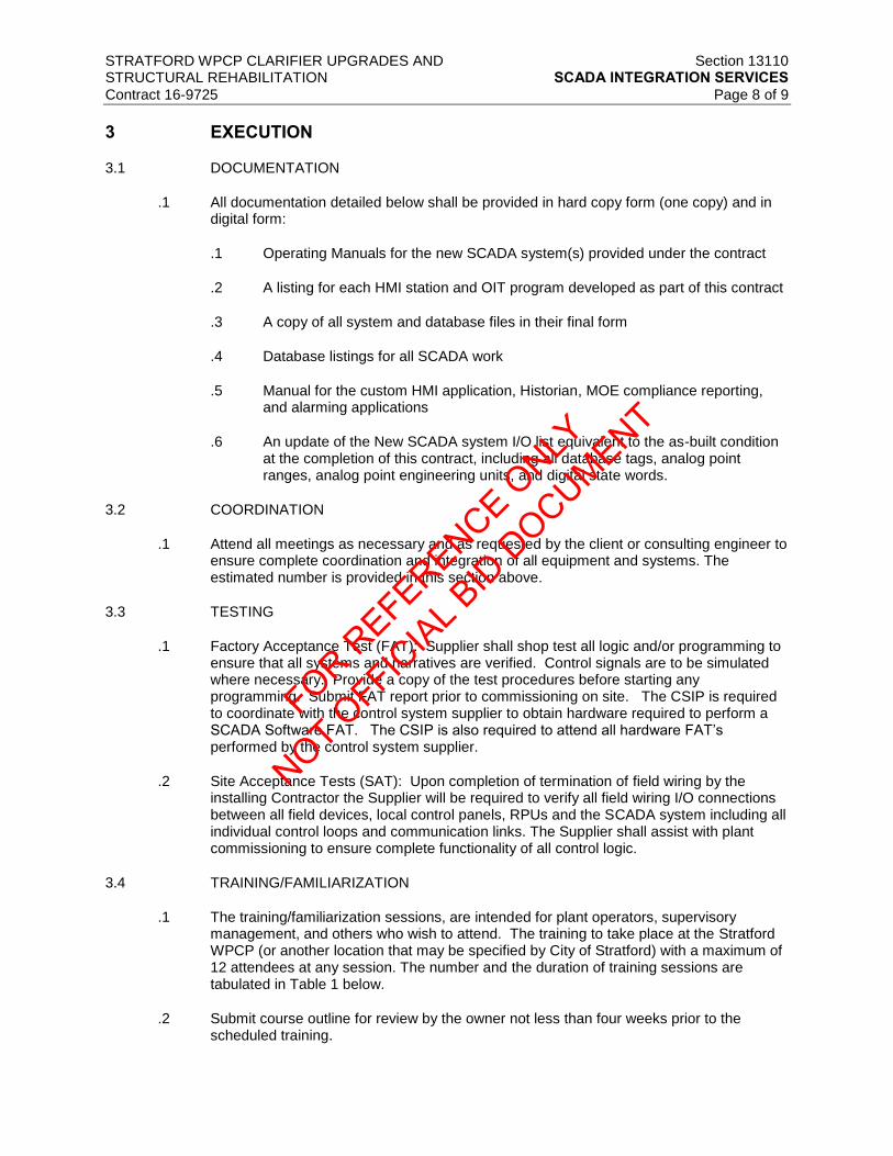
STRATFORD WPCP CLARIFIER UPGRADES AND Section 13110 STRUCTURAL REHABILITATION SCADA INTEGRATION SERVICES
Contract 16-9725 Page 8 of 9
3 EXECUTION
3.1 DOCUMENTATION
.1 All documentation detailed below shall be provided in hard copy form (one copy) and in digital form:
.1 Operating Manuals for the new SCADA system(s) provided under the contract
.2 A listing for each HMI station and OIT program developed as part of this contract
.3 A copy of all system and database files in their final form
.4 Database listings for all SCADA work
.5 Manual for the custom HMI application, Historian, MOE compliance reporting, and alarming applications
.6 An update of the New SCADA system I/O list equivalent to the as-built condition at the completion of this contract, including all database tags, analog point ranges, analog point engineering units, and digital state words.
3.2 COORDINATION
.1 Attend all meetings as necessary and as requested by the client or consulting engineer to ensure complete coordination and integration of all equipment and systems. The estimated number is provided in this section above.
3.3 TESTING
.1 Factory Acceptance Test (FAT): Supplier shall shop test all logic and/or programming to ensure that all systems and narratives are verified. Control signals are to be simulated where necessary. Provide a copy of the test procedures before starting any programming. Submit FAT report prior to commissioning on site. The CSIP is required to coordinate with the control system supplier to obtain hardware required to perform a SCADA Software FAT. The CSIP is also required to attend all hardware FAT’s performed by the control system supplier.
.2 Site Acceptance Tests (SAT): Upon completion of termination of field wiring by the installing Contractor the Supplier will be required to verify all field wiring I/O connections between all field devices, local control panels, RPUs and the SCADA system including all individual control loops and communication links. The Supplier shall assist with plant commissioning to ensure complete functionality of all control logic.
3.4 TRAINING/FAMILIARIZATION
.1 The training/familiarization sessions, are intended for plant operators, supervisory management, and others who wish to attend. The training to take place at the Stratford WPCP (or another location that may be specified by City of Stratford) with a maximum of 12 attendees at any session. The number and the duration of training sessions are tabulated in Table 1 below.
.2 Submit course outline for review by the owner not less than four weeks prior to the scheduled training.
FOR REFERENCE O
NLY
NOT OFFIC
IAL B
ID D
OCUMENT

STRATFORD WPCP CLARIFIER UPGRADES AND Section 13110 STRUCTURAL REHABILITATION SCADA INTEGRATION SERVICES
Contract 16-9725 Page 9 of 9
Table 1 Training Sessions
Training
SCADA System Two (2) separate sessions each for PLC/SCADA, HMI applications, Historian, Reporting, alarming and vendor supplied packages; duration as required
3.5 WARRANTY PERIOD SERVICE
.1 Identify in the financial Proposal the additional cost per day to provide trained process/software technician during the warranty period. The additional cost shall include travel and disbursements for the proponent to respond to a request for site assist ance within 3 business days of being contacted. Additional payment will not be authorized for services during the warranty period required to resolve deficient work.
END OF SECTION
FOR REFERENCE O
NLY
NOT OFFIC
IAL B
ID D
OCUMENT

FOR REFERENCE O
NLY
NOT OFFIC
IAL B
ID D
OCUMENT
STRATFORD WPCP CLARIFIER UPGRADES AND Section 13560 STRUCTURAL REHABILITATION INSTRUMENTATION GENERAL REQUIREMENTS Contract 16-9725 Page 1 of 13
1 GENERAL
1.1 RELATED SECTIONS
.1 Section 01330 – Submittal Procedures
.2 Section 01820 – Demonstration and Training
.3 Section 11190 – Pipe, Valve and Instrument Supports
.4 Section 11290 – Valve and Gate Actuators
.5 Section 13100 – Control & Instrumentation
.6 Section 13563 – Pressure and Level Instruments
.7 Section 13565 – Miscellaneous Instruments and Accessories
.8 Section 16010 – Electrical General Requirements
1.2 SCOPE
.1 This section covers the furnishing of all instrumentation equipment required for the Control & Instrumentation System as indicated on the drawings and the sections herein.
.2 Principal components of the instrumentation systems shall be as indicated on the P&ID drawings. The contractor is required to provide all instruments including electronic/electrical and non-electronic/electrical instruments.
.3 Provide product submittal data sheets for all instrumentation supplied under this project in the format identified in Appendix 1 of this section.
.4 Section 13100 shall apply to all systems described in this section. All applicable requirements defined in Section 13100 shall apply to equipment and services provided under Section 13560. Equipment and services in this section shall be provided by the Section 13100 – Control and Instrumentation.
1.3 GENERAL
.1 The Control System Supplier (CSS) shall select the equipment furnished under this section for its superior quality and the intended performance. The CSS shall install all equipment in accordance with the manufacturer's instructions. Equipment and materials used shall be subject to review and shall comply with the following requirements.
.2 Refer to Division 1 specifications for general equipment requirements which shall apply to all equipment furnished under this section.
.3 Supplementing this section, the drawings indicate locations and arrangement of instruments and enclosures, provide mounting details, and may show device schedules and other information regarding the connection and interaction with other equipment.
.4 Governing Standards for instruments shall be as indicated in Section 13100.
.5 All parts, which are exposed to corrosive conditions, shall be made from corrosion resistant materials. CSS shall submit certification that the instrument manufacturer
FOR REFERENCE O
NLY
NOT OFFIC
IAL B
ID D
OCUMENT

STRATFORD WPCP CLARIFIER UPGRADES AND Section 13560 STRUCTURAL REHABILITATION INSTRUMENTATION GENERAL REQUIREMENTS Contract 16-9725 Page 2 of 13
approves the selection of materials of primary elements that are in contact with the specified process fluid to be inert to the effects of the process fluid.
.6 Elevation and Temperature. All instruments shall be designed to operate within a range of elevation and temperature as required.
.7 Power and Instrument Signals. Unless otherwise indicated, electric power supply to the instrumentation equipment will be unregulated 120VAC and emergency electrical power will be from a diesel generator. All line powered instruments suitable for use on these supplies shall be provided with appropriate CSA approval. Line voltage ac powered instrument not CSA certified must bear an Ontario Hydro Special Approvals Branch label.
.8 Unless otherwise indicated, all transmitted electronic analog instrument signals shall be 4-20 mA DC and shall be linear with the measured variable.
.9 Appurtenances. Signal converters, signal boosters, amplifiers, special power supplies, special cable, special grounding, and isolation devices shall be furnished as needed for proper performance of the equipment.
.10 Interchangeability and Appearance. To the extent possible, instruments used for similar types of functions and services shall be of the same brand and model line. Similar components of different instruments shall be the products of the same manufacturer to facilitate maintenance and stocking of repair parts. Whenever possible, identical units shall be furnished.
.11 Programming Devices. A programming or system-configuring device shall be provided for systems that contain equipment that requires such a device for routine calibration, maintenance, and troubleshooting. The programming device shall be complete, newly purchased for this project, and shall be in like-new condition when turned over to City of Startford at completion of startup.
.12 At least one smart instrument calibration device shall be provided for every 10 smart instruments. Rosemount model 275 HART Communicator complete with memory pack 100 and AA battery packer or vendor equivalent shall be provided.
.13 Device Tag Numbering System. All devices shall be provided with permanent identification tags. The tag numbers shall agree with CSS'S equipment drawings and shall be as close as practical to the tag numbers used on the project drawings and device schedules. All field-mounted transmitters and devices shall have stamped stainless steel identification tags. Panel, subpanel, and rack-mounted devices shall have laminated phenolic identification tags securely fastened to the device. Hand-lettered or tape labels will not be acceptable.
.14 Indoor Installation. Unless otherwise shown or specified, enclosures for all instruments located indoors in dry hazardous areas shall be as a minimum EEMAC12.
.15 Outdoor Installation. Unless otherwise shown or specified, instruments located outdoors shall be suitable for the surrounding climate and appropriately installed with:
.16 An EEMAC4 enclosure including gasketed windows for displays, containing a thermostatically controlled heater and disconnect switch – minimum typical enclosure to be an O Brien VIPAK series or equal.
.17 A combined rain/ice/snow protection shield and sun shade for all electronic instruments which are already provided with sturdy EEMAC4 enclosures by the manufacturer. Supply tip-up type hoods for access for routine calibration and maintenance.
.18 Drawing submissions must clearly show the enclosures proposed for each instrument.
FOR REFERENCE O
NLY
NOT OFFIC
IAL B
ID D
OCUMENT

STRATFORD WPCP CLARIFIER UPGRADES AND Section 13560 STRUCTURAL REHABILITATION INSTRUMENTATION GENERAL REQUIREMENTS Contract 16-9725 Page 3 of 13
.19 Unless otherwise shown or specified, instruments located in hazardous areas shall be
provided with Canadian Electrical Code ratings for class, group, and division as shown.
.20 Unless otherwise shown or specified, instruments located in areas subjected to flooding shall be provided submergence rated enclosures.
.21 Heat tracing. Electrically heat traced sensing lines for instruments with sensing lines liable to freezing shall be provided as needed.
.22 All instruments to be installed in the classified area shall be explosion proof.
1.4 SUBMITTALS
.1 Submittals shall be as required in Section 13100 - Control and Instrumentation System and Section 01330 – Submittal.
.2 Product Data Sheets. Provide completed product Data Sheets specifying instruments and equipment conforming to ISA specification sheet standards. Complete blank spaces on these sheets with the information noted below and other data pertinent to the equipment and the application.
.1 Use the product data sheet for documenting installation and testing.
.2 Include the following upon initial submission (to accompany Shop Drawings):
.1 Project Name
.2 Tag number and description.
.3 Manufacturer, Model and Part Numbers.
.4 Identification Nameplate details.
.5 The product manufacturer and the supplier or representative.
.6 The complete model and catalogue numbers including special options.
.7 The available adjustment ranges and the project operating ranges.
.8 Web link for each product manufacturer.
.9 On each sheet, add the following information following field calibration:
.1 Serial numbers.
.2 Date of installation.
.3 Date, time and person who performed calibration.
.4 Calibration data.
.5 Input, output, and error at 0, 25, 50, 75, 100 per cent of span for analog instrument.
.6 Switch setting, contact action, and dead band, if applicable, for discreet elements.
FOR REFERENCE O
NLY
NOT OFFIC
IAL B
ID D
OCUMENT

STRATFORD WPCP CLARIFIER UPGRADES AND Section 13560 STRUCTURAL REHABILITATION INSTRUMENTATION GENERAL REQUIREMENTS Contract 16-9725 Page 4 of 13
.7 Certification by installer and acknowledgement by contractor.
.8 Special procedures and equipment required to duplicate calibration.
.9 Comments, including calibration changes, repair or replacement works performed.
.10 Add the following upon final submission (immediately following site acceptance):
.1 Signature by the Contractor and the Engineer indicating acceptance.
.2 Phone and fax numbers of contact person for product support/service.
.3 Provide a completed Instrumentation Installation “Checklist” form for each instrument.
1.5 DELIVERY, STORAGE, AND SHIPPING
.1 Delivery, storage and shipping shall be as required in Division 1 and Section 13100.
1.6 SPARE PARTS
.1 Spare parts shall be provided as following: duplicated full set of lamps for indicating lights, terminal blocks, fuses, breakers, relays and timers.
.2 Supply spare parts required to commission instruments. Include five spare fuses of each type for each instrument panel.
2 PRODUCTS
2.1 INDIVIDUAL DEVICE SPECIFICATIONS
.1 Individual instruments and related devices shall be provided as specified in the following sections:
.2 Section 11190 – Pipe, Valve and Instrument Supports
.3 Section 11290 – Valve and Gate Actuators
.4 Section 13100 – Control and Instrumentation
.5 Section 13563 – Pressure and Level Instruments
.6 Section 13565 – Miscellaneous Instruments and Accessories
3 EXECUTION
3.1 INSTRUMENTATION INSTALLATION REQUIREMENTS
.1 Additional instrumentation installation requirements are specified in Section 13100.
.2 No instrumentation field wiring shall be continuous, no splices.
FOR REFERENCE O
NLY
NOT OFFIC
IAL B
ID D
OCUMENT

STRATFORD WPCP CLARIFIER UPGRADES AND Section 13560 STRUCTURAL REHABILITATION INSTRUMENTATION GENERAL REQUIREMENTS Contract 16-9725 Page 5 of 13
.3 Complete an Instrumentation Installation Checklist Form and Instrumentation Calibration
Form for each instrument that is tested and commissioned. Testing and commissioning of the instruments will be considered incomplete unless the respective instrument is provided with an Instrumentation Calibration Form, with all fields completed. The contractor shall provide a typed version of the all completed calibration forms to be included in the maintenance manual.
.4 Field Calibration. After each instrument has been installed, a technical representative of CSS shall calibrate each instrument and shall provide a written calibration report for each instrument, indicating the results and final settings. The adjustments of calibrated instruments shall be sealed or marked, insofar as possible, to discourage tampering. Instrument calibration shall be done before checkout of the system operation. A typical instrument calibration form and Instrumentation Installation Checklist form is attached to the end of each section.
.5 Systems Check. A technical representative of CSS shall participate in the checkout of instrumentation systems. Systems check requirements shall be as specified in Section 13100.
.6 Installation Test Equipment. Unless specified otherwise, all test equipment for the calibration and checking of system components shall be provided by CSS for the duration of the testing work and this test equipment will remain the property of CSS.
.7 Mounting of Field Instruments. Instruments shall be mounted so that they can be easily read and serviced and so that all appurtenant devices can be easily operated. Installation details for some instruments are indicated on the drawings. Where installation details are not indicated, the installation performed by the CSSs shall conform to the manufacturer’s instructions and/or API RP 550 recommendations.
.1 Unless otherwise shown or specified, all required mounting hardware, enclosures, termination’s, junction boxes, etc., shall be provided. Refer to the tender drawings and the manufacturer’s documentation to confirm the necessary hardware and construction for specific mounting assemblies where such details are not specified herein.
.2 No instruments shall be mounted on vibrating structures (e.g. handrails), or on piping or near equipment that induces vibration. No instruments shall be mounted below or directly adjacent to lines conveying corrosive chemicals or near sources of leakage or spillage.
.3 Metal surfaces shall be prepared and supports or frames shall be painted the same color as the member of the complete assembly is mounted on.
.4 Unless otherwise shown or specified, instruments shall be mounted 1.4m above finished floors, grade or platforms. Allow for cabinet plinth/floor-pad heights when locating panel instruments. Instruments that are not easily accessible for operation or maintenance, or indicator that is not easily and readily visible must be relocated as directed by the Engineer at no cost to the contract.
.5 When drilling or installing conduit entry points in instruments, protect internally mounted equipment from vibration, shock and metal filings. Conduit entries much maintain the equipment or panel EEMAC rating.
.6 Lengths for transducer cables and similar items shall be field measured prior to ordering. Cables shall be mechanically protected and adequately secured in place without sagging.
.7 All instruments shall be provided with isolation valves.
FOR REFERENCE O
NLY
NOT OFFIC
IAL B
ID D
OCUMENT

STRATFORD WPCP CLARIFIER UPGRADES AND Section 13560 STRUCTURAL REHABILITATION INSTRUMENTATION GENERAL REQUIREMENTS Contract 16-9725 Page 6 of 13
.8 All instrument cables shall be protected with capillaries throughout their length
without sagging by using painted/galvanized angle iron and clips. Avoid sharp bends in capillary and coil excess close to the sensor end. Protect the coiled capillary by clipping to a steel plate or other safe method.
.9 Sensing and sample lines shall be run in ½” stainless steel tubing with “Swagelok” compression type fittings.
.10 Install process sample piping and sensing lines to avoid accumulation of vapor or gas in liquid service and of liquid or condensate on vapor or gas service as appropriate.
.11 Instruments shall be positioned so that they do not block or obstruct walkways or access points and adequate space shall be provided around installation for removal of covers, etc.
.12 Instrument support brackets shall not be welded to process piping or equipment, but should generally be pedestal or wall mounted.
.13 Field cables for analogue signals shall be run in separate conduit from 120V AC/24VDC control or 120VAC power supply cables.
.14 Field junction boxes suitable for the area classification to “marshal” groups of signals of the same type in an area and cable back to buildings and local control panel with multi-core cables shall be used.
.15 Junction boxes may be FRP (fiberglass reinforced plastic) or similar material suitable for the area and rust and weather resistant. Terminals inside field junction boxes are to be DIN rail mounted.
.16 Once an instrument has been inspected by the Engineer and initially calibrated, it is to remain powered up at all times unless servicing the instrument itself. Keepers shall be installed immediately on all panel circuit breakers powering instruments.
.17 Instrument calibration, setpoints and other programmable parameters are to be confirmed with the Engineer during on-site inspection as soon as site conditions are sufficiently ready. Final calibration values may be adjusted to values different than the nominal values specified in the Product Data Sheets at no extra cost to the contract.
3.2 CUSTOMER TRAINING
.1 Provide Instrumentation training in accordance with Section 13100 and Section 01820 Demonstration and Training.
3.3 FORMS
.1 Complete an Instrumentation Installation Checklist Form and Instrumentation Calibration Form for each instrument that is tested and commissioned.
FOR REFERENCE O
NLY
NOT OFFIC
IAL B
ID D
OCUMENT

STRATFORD WPCP CLARIFIER UPGRADES AND Section 13560 STRUCTURAL REHABILITATION INSTRUMENTATION GENERAL REQUIREMENTS Contract 16-9725 Page 7 of 13
Instrumentation Installation Checklist
Project Name: Project Number:
Contractor: Contract Number:
EQUIPMENT:
DATE INSTALLATION
COMPLETE:
SERIAL NO.: MAKE AND MODEL NO.:
PRE-START-UP CHECKED BY DATE REMARKS
Installation/Mounting
Sensor/Transmitter
Wiring/Conduit Termination
and Seals
Check Fuse Ratings (Supply
and Internal)
Tagging/Nameplate
Compliance Section 16
Test (Ground Loop, Continuity,
Installation)
Power Supply
Check Instrument Air/Adjust
Filter/Regulator
Check Temp. Control
(Internal/Heat Tracing)
Configure Calibration
Tailback lights
START-UP
Verify Operation Under Max
Process
Conditions
Correct Quantities of
FOR REFERENCE O
NLY
NOT OFFIC
IAL B
ID D
OCUMENT

STRATFORD WPCP CLARIFIER UPGRADES AND Section 13560 STRUCTURAL REHABILITATION INSTRUMENTATION GENERAL REQUIREMENTS Contract 16-9725 Page 8 of 13
Expandable Material
* Indicates (N/A) if not
applicable
Comments:
FOR REFERENCE O
NLY
NOT OFFIC
IAL B
ID D
OCUMENT

STRATFORD WPCP CLARIFIER UPGRADES AND Section 13560 STRUCTURAL REHABILITATION INSTRUMENTATION GENERAL REQUIREMENTS Contract 16-9725 Page 9 of 13
Inspection Result Passed Installation and Start-up
checkout. Equipment certified
ready for service
Failed – Contractor to schedule
equipment re-inspection
Contractor Supplier
Date Date
Consultant Region/Operator
Date Date
FOR REFERENCE O
NLY
NOT OFFIC
IAL B
ID D
OCUMENT
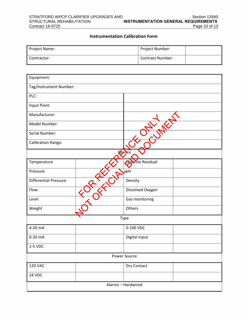
STRATFORD WPCP CLARIFIER UPGRADES AND Section 13560 STRUCTURAL REHABILITATION INSTRUMENTATION GENERAL REQUIREMENTS Contract 16-9725 Page 10 of 13
Instrumentation Calibration Form
Project Name: Project Number:
Contractor: Contract Number:
Equipment:
Tag/Instrument Number:
PLC:
Input Point:
Manufacturer:
Model Number:
Serial Number:
Calibration Range:
Service
Temperature Chlorine Residual
Pressure pH
Differential Pressure Density
Flow Dissolved Oxygen
Level Gas monitoring
Weight Others
Type
4-20 mA 0-100 VDC
0-20 mA Digital Input
1-5 VDC
Power Source
120 VAC Dry Contact
24 VDC
Alarms – Hardwired
FOR REFERENCE O
NLY
NOT OFFIC
IAL B
ID D
OCUMENT

STRATFORD WPCP CLARIFIER UPGRADES AND Section 13560 STRUCTURAL REHABILITATION INSTRUMENTATION GENERAL REQUIREMENTS Contract 16-9725 Page 11 of 13
HIHI LO
HI LOLO
Failure
FOR REFERENCE O
NLY
NOT OFFIC
IAL B
ID D
OCUMENT
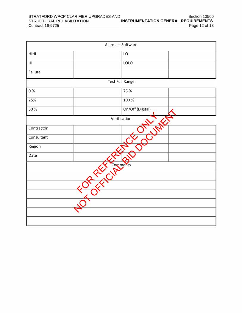
STRATFORD WPCP CLARIFIER UPGRADES AND Section 13560 STRUCTURAL REHABILITATION INSTRUMENTATION GENERAL REQUIREMENTS Contract 16-9725 Page 12 of 13
Alarms – Software
HIHI LO
HI LOLO
Failure
Test Full Range
0 % 75 %
25% 100 %
50 % On/Off (Digital)
Verification
Contractor
Consultant
Region
Date
Comments
FOR REFERENCE O
NLY
NOT OFFIC
IAL B
ID D
OCUMENT

STRATFORD WPCP CLARIFIER UPGRADES AND Section 13560 STRUCTURAL REHABILITATION INSTRUMENTATION GENERAL REQUIREMENTS Contract 16-9725 Page 13 of 13
Inspection Result Passed Installation and Start-up
checkout. Equipment certified
ready for service
Failed – Contractor to schedule
equipment re-inspection
Contractor Supplier
Date Date
Consultant Region/Operator
Date Date
END OF SECTION
FOR REFERENCE O
NLY
NOT OFFIC
IAL B
ID D
OCUMENT

FOR REFERENCE O
NLY
NOT OFFIC
IAL B
ID D
OCUMENT

STRATFORD WPCP CLARIFIER UPGRADES AND Section 13563 STRUCTURAL REHABILITATION LEVEL INSTRUMENT
Contract 16-9725 Page 1 of 3
1 GENERAL
1.1 RELATED SECTIONS
.1 DIVISION 11 - EQUIPMENT
.2 DIVISION 13 - CONTROL & INSTRUMENTATION
.3 DIVISION 16 - ELECTRICAL
1.2 DESIGN CRITERIA
.1 Each device shall be a pre-assembled, packaged unit. Upon delivery to the work site, each device or system shall be ready for installation with only minor piping and electrical connections required by CONTRACTOR.
.2 Primary elements shall derive any required power from the transmitter, unless otherwise indicated.
.3 The instruments shall be installed to measure, monitor, or display the specified process at the ranges and service conditions indicated on the drawings or as indicated in the Instrument Device Schedule. The instrument shall be installed at the locations indicated on the drawings.
.4 Where possible, each instrument shall be factory calibrated to the calibration ranges indicated in the drawings or in the Instrument Device Schedule. Transmitters or similar measurement instruments shall be calibrated using National Institute of Standards and Technology (NIST) approved bench calibration procedures, when such procedures exist for the instrument type. For "smart" devices, calibration data shall be stored digitally in each device, including the instrument tag designation indicated on the drawings and/or Instrument Device Schedule.
1.3 SUBMITTALS
.1 Submittals shall be made in accordance with the requirements of Section 01330
2 PRODUCTS
2.1 GENERAL
.1 The following paragraphs provide minimum device requirements. The drawings or Instrument Device Schedule shall be used to determine any additional instrument options, requirements, or service conditions.
.2 Interconnecting Cable. For systems where the primary element and transmitter are physically separated, interconnecting cable from the element to the transmitter shall be provided. The cable shall be the type approved by the instrument manufacturer for the intended purpose of interfacing the element to the transmitter. Length of cable shall be a minimum of three meters or as indicated in the drawings or Instrument Device Schedule.
.3 Programming Device. For systems that require a dedicated programming device for calibration, maintenance, or troubleshooting, one such programming device shall be provided for the City of Stratford facility. The programming device shall include appropriate operation manuals and shall be included in the training requirements. For systems that allow the programming device functions to be implemented in software,
FOR REFERENCE O
NLY
NOT OFFIC
IAL B
ID D
OCUMENT

STRATFORD WPCP CLARIFIER UPGRADES AND Section 13563 STRUCTURAL REHABILITATION LEVEL INSTRUMENT
Contract 16-9725 Page 2 of 3
running on a laptop computer, the software shall be provided instead of the programming device.
.4 The programming device shall be complete, newly purchased for this project, and shall be in like-new condition when turned over to the City of Stratford at completion of startup.
.5 Configuration Software/Serial Interface. Devices indicated as requiring a serial interface shall be provided with all accessories required to properly communicate over the serial link. As a minimum, an appropriate cable shall be provided to allow the transmitter serial interface to be connected to a personal computer. One licensed copy of the diagnostic/interface software shall be provided for the City of Stratford facility. Software shall be capable of running under Microsoft’s and Windows XP or 7 operating system. If the software furnished performs the same functions as the programming device, specified elsewhere, then the programming device shall not be furnished.
2.2 LEVEL INSTRUMENTATION
.1 Ultrasonic Level Transmitters. Each ultrasonic level transmitter shall be a microprocessor based electronic unit consisting of a sensor assembly, a signal converter/transmitter, and an interconnecting cable if necessary and if suitable for the application. The sensor shall be encapsulated in a chemical and corrosion resistant material such as kynar or CPVC, and shall be suitable for operation over a temperature range of -45° to 90°C and a relative humidity of 100 percent condensing. The sensor shall be compatible with the process media being measured. Sensors mounted in areas subject to freezing shall be provided with special transducers or protected against icing by heaters. Sensors mounted in direct sunlight shall be provided with sunshades.
.1 The supplier shall coordinate the sensor mounting requirements and furnish drawings complete with dimensions and elevations. General installation requirements are indicated on the drawings.
.2 The ultrasonic level transmitter shall have automatic compensation for changes in air temperature at the sensor location. If separate temperature sensing probes are provided, they shall be mounted with or adjacent to the ultrasonic sensor, as recommended by the manufacturer. The transmitter shall have a local backlit LCD, which displays level in engineering units, with additional indicators for alarms and status conditions. Digit height shall be approximately 12 mm. The transmitter shall be designed to ignore momentary level spikes, false targets, or momentary loss of echo. A loss of echo condition shall be indicated on the transmitter unit and shall be available as an alarm contact output. The loss-of-echo alarm shall fail to “Hold Last State” position after five (5) minutes. The transmitter output shall be an isolated 4 20 mA dc signal linearly proportional to the measured level range. Calibration parameters shall be entered through a keypad on the unit and shall be stored in nonvolatile EEPROM memory. Transmitters shall have Microsoft windows based graphical programming software and RS-485 interface. Accuracy of the transmitted signal shall be +/-0.25 % of full scale with repeatability of +/-0.5% of full scale and linearity of +/-0.5% of full scale.
.3 Transmitters shall contain four independently adjustable level alarm contact outputs. Contacts shall be single-pole, double-throw rated not less than 5 amperes at 120 V ac.
.4 A sufficient length of sensor to transmitter signal cable shall be furnished with the instrument to locate the sensor 7.6 to 61 m from the signal converter.
FOR REFERENCE O
NLY
NOT OFFIC
IAL B
ID D
OCUMENT

STRATFORD WPCP CLARIFIER UPGRADES AND Section 13563 STRUCTURAL REHABILITATION LEVEL INSTRUMENT
Contract 16-9725 Page 3 of 3
.5 Transmitters shall at minimum be enclosed in a NEMA Type 4X housing. Where
transmitters are installed in Class 1, Division 1 environments, the transmitter shall be certified for such areas. When ultrasonic level instruments are comprised of separate transmitters and sensor units, the transmitter enclosures shall be suitable for wall or pipestand mounting.
.6 Ultrasonic level instruments to be installed outdoors shall be capable of operating at temperatures of -26° to +51°C and a relative humidity of 10 to 100 percent. A thermostatically controlled strip heater shall be provided in the signal converter enclosure.
.7 Acceptable Product: Ultrasonic level monitor/controller (Siemens-Milltronics Multiranger 100) complete with XPS-15 transducer.
.8 If the installation location is not shown on the Contract Drawings, the Contractor shall coordinate with the Engineer, the location of transducer and monitor/controller, but no extra cost of installation is allowed.
.2 Three (3) level transmitters including transducers shall be provided in the following locations:
.1 One (1) in the primary clarifier distribution chamber.
.2 Two (2) in each valve chamber.
3 EXECUTION
3.1 FIELD SERVICES
.1 Manufacturer's field services shall be provided for installation, field calibration, startup, and training as specified in Sections 13100.
.2 Instruments shall not be shipped to the Work Site until two weeks prior to the scheduled installation. CSS shall be responsible for coordinating the installation schedule with the Installation Contractor. Each shipment shall contain a listing of protective measures required to maintain sensor operation, including a listing of any common construction or cleaning chemicals that may affect instrument operation.
END OF SECTION
FOR REFERENCE O
NLY
NOT OFFIC
IAL B
ID D
OCUMENT

FOR REFERENCE O
NLY
NOT OFFIC
IAL B
ID D
OCUMENT

STRATFORD WPCP CLARIFIER UPGRADES AND Division 16 STRUCTUAL REHABILITATION Contract No. 16-9725
DIVISION 16 – ELECTRICAL
FOR REFERENCE O
NLY
NOT OFFIC
IAL B
ID D
OCUMENT

FOR REFERENCE O
NLY
NOT OFFIC
IAL B
ID D
OCUMENT

STRATFORD WPCP CLARIFIER UPGRADES AND Division 16 STRUCTUAL REHABILITATION TABLE OF CONTENTS Contract No. 16-9725 i
DIVISION 16 – ELECTRICAL
Section No. Title
16010 Electrical General Requirements
16015 Electrical Systems Analysis
16020 Sequence of Activities
16021 Demolition of Electrical Systems
16051 Installation of Cables in Ducts and Trenches
16062 Grounding – Secondary
16090 Equipment Identification
16122 Wires and Cables 0 – 1000V
16132 Outlet Boxes, Conduit Boxes and Fittings
16133 Conduits, Conduit Fastenings and Conduit Fittings
16141 Wiring Devices
16400 Basic Electrical Equipment & Materials
16412 Molded Case Circuit Breakers
16414 Disconnect Switches – Fused & Unfused
16441 Panel-boards Breaker Type
16671 Surge Protective Devices
FOR R
EFERENCE ONLY
NOT OFFIC
IAL B
ID D
OCUMENT

FOR REFERENCE O
NLY
NOT OFFIC
IAL B
ID D
OCUMENT

STRATFORD WPCP CLARIFIER UPGRADES AND Section 16010 STRUCTUAL REHABILITATION ELECTRICAL GENERAL REQUIREMENTS Contract No. 16-9725 Page 1 of 23
1 GENERAL
1.1 DESCRIPTION
.1 This section describes the following:
.1 General and common requirements for Division 16 (Electrical Work)
.2 Overall scope of work for Division 16
.3 General coordination between Division 16 and related work in other Divisions
1.2 GENERAL
.1 Read and conform to the General Requirements (Division 1), which applies to and forms part of all sections of the work. The general instructions are intended to supplement and not to replace Division 1 requirements.
.2 The specifications are divided into Divisions of work and a Division may consist of the work of more than one (1) subcontractor. The responsibility as to which subcontractor provides labour, materials, equipment and services required to complete the work rests solely with the Contractor.
.3 Furnish, install, test and commission a complete operational electrical system as required by the drawings and as herein specified.
.4 The Contractor shall provide all power and control conduit and wiring as required for all process equipment and for equipment supplied under other Divisions, as shown on the drawings and/or specified herein.
.5 The Contractor shall provide all labour, supervision, tools, equipment, materials, services and miscellaneous expenses necessary to complete the work as outlined in this Section. Install and connect all electrical and instrumentation equipment, controls and devices supplied under other sections.
.6 Remove existing equipment made obsolete by this project and also disconnect/reconnect existing equipment either relocated or serviced from new equipment.
.7 Visually inspect the existing building conditions, including below grade areas, prior to the project award to suit the installation of the new power and controls distribution.
.8 Remove and dispose of existing equipment made obsolete by this project.
.9 Electrical equipment shop drawings will not be reviewed unless they are preceded by or accompanied with a copy of the electrical protection, coordination and arc flash study. The electrical equipment shop drawings will be returned as rejected, if submitted prior to the protection, coordination and arc flash study
1.3 SCOPE OF WORK
.1 Retain original MCC manufacturer to supply & install a new 600V, 100A, 3PH breaker in a spare bucket on MCC-B in chemical building as shown on the drawings. Retain original MCC manufacturer to make modifications to the MCC as required. The new breaker make & model shall match existing. Provide all other hardware for the breaker compartment as required including door, breaker handle, internal bolts, joints, etc. Provide a level on the new MCC breaker to state “DP-01”.
FOR REFERENCE O
NLY
NOT OFFIC
IAL B
ID D
OCUMENT

STRATFORD WPCP CLARIFIER UPGRADES AND Section 16010 STRUCTUAL REHABILITATION ELECTRICAL GENERAL REQUIREMENTS Contract No. 16-9725 Page 2 of 23
.2 Supply and install new 600V, 225A, 3PH, 3W distribution panel, DP-01, inside the chemical building electrical room as shown on the drawings. The panelboard shall be wall mounted and complete with a surge protection device.
.3 Provide wires & conduits inside the electrical room, valve chambers and distribution chamber to feed new equipment. Wires & conduits shall be installed in accordance with requirements of sections 16122, 16132 and 16133. Determined conduit routes on site.
.4 Provide underground ductbanks including concrete encased as indicted on the drawings. Underground ductbank routes shall be finalized on site.
.5 Provide all new power distribution equipment, wires, conduits, junction boxes as indicated on contract drawings.
.6 Coordinate with other disciplines, including Division 11, for installation of process electrical equipment such as actuator valves. The actuators are to be supplied by Division 11.
.7 Coordinate with Division 13 for retrofit of existing control panel, ICP-B, to accommodate new I/Os.
.8 Minimize shutdown to perform all work. Provide a sequence of construction and a work plan prior to construction.
.9 Wires and conduit runs shall be finalized on site and installed in a concealed manner in public areas.
.10 Demolition
.1 Refer to contract drawings for removal details of existing electrical equipment.
.11 Testing/Installation and Operation Verification/Commissioning
.1 Installation Verification
.1 The Contractor shall document on site and during the time of installation the key aspects of the installation to verify that the installation is in compliance with the project specifications.
.2 This procedure must be performed by the Contractor’s site supervisor. This Installation Verification documentation shall include the following.
.1 The device or component has been installed in the specified location and installed in the correct orientation.
.2 All wiring installation work (i.e. power, communication, instrumentation, control) is complete, connection are correct as per the drawings and manufacturer’s specifications, and all connections have been tested for secureness.
.3 Tags and labels are in place and inscriptions match the data provided on the drawings.
.4 The device or component is clean and in good order (i.e. undamaged or if required, scratches painted).
FOR REFERENCE O
NLY
NOT OFFIC
IAL B
ID D
OCUMENT

STRATFORD WPCP CLARIFIER UPGRADES AND Section 16010 STRUCTUAL REHABILITATION ELECTRICAL GENERAL REQUIREMENTS Contract No. 16-9725 Page 3 of 23
.5 Manuals, tools, spare parts and materials supplied with the device or component are stored in a safe location on site and accessible for retrieval.
.6 Feeder and branch circuit wiring has been megger checked.
.7 All installation deficiencies have been addressed.
.2 Operation Verification
.1 The Operation Verification documents that the device or component performs consistently throughout its specified operating range. The Contractor shall perform the Operation Verification for a device or component only after the device and component has successfully passed the Installation Verification. The Operation Verification is performed on the device or component as a system.
.2 This procedure must be performed by the Contractor’s site supervisor. This Operation Verification documentation shall include the following.
.3 All power phases and phase voltages are within specification.
.4 Motor rotation is correct.
.5 The device or component is powered up and ready to operate.
.6 The device or component configuration and calibration is complete and as per specification.
.7 The device or component can be operated throughout its entire range.
.8 All features and functions of the device or component operate as expected and as specified.
.9 All operational deficiencies have been addressed.
.3 Test and commission all new and modified equipment, power distribution and control systems.
.12 Clean all electrical equipment.
.13 Provide training for all equipment supplied under this Division.
.14 Short Circuit, Protection Co-ordination and Arc Flash Study
.1 Provide a short circuit, protection coordination and arc flash hazard study. Labels are to be provided by the Contractor based on the study findings. Recommended settings are to be implemented by the Contractor.
.2 Studies are to be submitted in advance of all other electrical equipment/distribution shop drawings.
1.4 RELATED SECTIONS
.1 Read and conform to all Sections of the specifications. References to specific sections of the specifications do not relieve the Contractor of the requirement to read and follow all sections as a complete document.
FOR REFERENCE O
NLY
NOT OFFIC
IAL B
ID D
OCUMENT

STRATFORD WPCP CLARIFIER UPGRADES AND Section 16010 STRUCTUAL REHABILITATION ELECTRICAL GENERAL REQUIREMENTS Contract No. 16-9725 Page 4 of 23
.2 The general instructions are intended to supplement and not to replace Division 1 requirements. Where requirements conflict, apply the more strenuous requirement.
.3 The drawings, specifications, and standards are complimentary to one another, meaning that, that which is called for on one is meant to be called for on all. Where conflict exists between the Sections, Standards and/or Drawings, obtain clarification from the Construction Manager before any material is purchased or work commences.
.4 If it is not clear from the Drawings and Specifications, which Division is responsible for performing certain works, obtain clarification of the item and/or items in question from the Construction Manager.
1.5 CODES AND STANDARDS
.1 All equipment and work shall meet or exceed the requirements of the Ontario Electrical Safety Code (OESC) and to all standards referenced therein.
.1 The OESC is CSA C22.1, Canadian Electrical Code, Part 1, and the Ontario Amendments to that Code
.2 All electrical equipment shall bear all required approval marks to demonstrate approval to all applicable codes and standards.
.2 Perform overhead systems in accordance with CSA C22.3 No.1 except where specified otherwise.
.3 Perform underground systems in accordance with CSA C22.3 No.7 except where specified otherwise.
.4 Code requirements shall be considered a minimum standard. When materials shown on drawings as indicated in the specifications exceed code requirements, the plans and specifications shall govern.
.5 All references to regulations, codes and standards shall be made to the latest edition.
1.6 DEFINITIONS
.1 The following are definitions of terms and expressions used in the specification:
.1 “Indicated” is defined as shown on the drawings or noted in contract documents.
.2 “Inspection Department/Authority” means an agent of any authority having jurisdiction over construction and safety standards associated with any part of electrical work on site. For this project the Inspection Authorities include:
.1 The Electrical Safety Authority (ESA)
.2 The Technical Safety and Standards Authority (TSSA)
.3 The local building inspector
.4 The local fire inspector
.3 “OESC” is defined as CSA C22.1, Canadian Electrical Code, Part 1, and the Ontario Amendments to that Code.
.4 “Provide” is defined as to supply install, verify, test and commission.
FOR REFERENCE O
NLY
NOT OFFIC
IAL B
ID D
OCUMENT

STRATFORD WPCP CLARIFIER UPGRADES AND Section 16010 STRUCTUAL REHABILITATION ELECTRICAL GENERAL REQUIREMENTS Contract No. 16-9725 Page 5 of 23
.5 “Supply Authority” is defined as the local electrical distribution company. For this project the Supply Authority is Energy Plus (Cambridge and North Dumfries Hydro).
.6 “Wiring” means wiring of power and control conductors to lighting, receptacles, as well as any controlling or controlled devices associated with them.
1.7 COORDINATION WITH OTHER TRADES
.1 The specification is divided into divisions of work and a division may consist of the work of more than one (1) subcontractor. The responsibility as to which subcontractor provides labour, materials, equipment and services required to complete the work rests solely with the Contractor.
.2 The Contractor shall be responsible for all electrical wiring and terminations required for equipment supplied in other Divisions, irrespective whether or not it is shown or mentioned on the drawings and specifications respectively so as to supply a complete working system.
.3 Where special wiring (cables supplied with instruments, etc.) is supplied by other Divisions, the Contractor will be responsible for the installation of this wiring in coordination with the Division supplying said wiring.
.4 Where equipment is supplied by other Divisions and installed under this Division:
.1 The Contractor shall be responsible for the proper installation of all panels, enclosures, switches, fixtures, etc., as shown on the drawings.
.2 Provide all terminations, junction boxes, fittings and flex connectors, such that raceway is continuous for its intended application. The Contractor shall be responsible for coordination with other Divisions supplying equipment, as to the exact location for installation of said equipment.
.3 Raceway types are to conform with to the space classification.
.4 The Contractor shall request from other Divisions supplying equipment for installation and/or wiring under this Division, all pertinent instruction manuals, diagrams, specifications sheets, etc., required for the proper installation of the equipment.
.5 The Contractor shall be responsible for verifying that the equipment’s electrical specifications are suitable for the intended application as per Division 1. Check all voltage ratings, wiring terminations, current ratings and other electrical characteristics so as to supply a complete working system.
1.8 PERMITS, FEES AND INSPECTION
.1 The Engineer shall obtain Electrical Safety Authority (ESA) plan review prior to commencement of work. The Contractor is required to comply with all recommendations and comments provided by the ESA in the plan review report, at no additional cost.
.2 Submit all necessary documentation to the ESA during the construction period including electrical distribution equipment shop drawings, short circuit protection coordination study and the arc flash hazard study. The Contractor shall abide by all comments and recommendations provided by the ESA based on the submitted information, at no additional cost.
FOR REFERENCE O
NLY
NOT OFFIC
IAL B
ID D
OCUMENT

STRATFORD WPCP CLARIFIER UPGRADES AND Section 16010 STRUCTUAL REHABILITATION ELECTRICAL GENERAL REQUIREMENTS Contract No. 16-9725 Page 6 of 23
.3 Notify the Construction Manager of changes required by Electrical Safety Authority (ESA) prior to making changes.
.4 Furnish Certificates of Acceptance from the ESA on completion of work to the Construction Manager.
.5 Arrange for inspection of all work by the Authorities having jurisdiction over the work. On completion of the work, present to the Owner the final unconditional certificate of approval of the Inspection Authorities.
.6 Before starting any work, submit the required number of copies of drawings and specifications to the Authorities for their approval and comments. Comply with any changes requested as part of the contract, but notify the Construction Manager immediately of such changes for proper processing of the requirements. Prepare and furnish any additional drawing details for information as may be required.
.7 The Contractor shall submit the following documentation to the Electrical Safety prior to proceeding with construction:
.1 Electrical Shop Drawings of all distribution Equipment including panelboards rated over 400A.
.2 Short Circuit and Protection Coordination Study
1.9 CONTRACT DRAWINGS AND SPECIFICATIONS
.1 Follow the Contract Drawings to become familiar with all conditions affecting the work, and verify spaces in which the work will be installed.
.2 The drawings for electrical work are performance drawings, diagrammatic, intended to convey the scope of work and indicate general arrangement and approximate location of apparatus, fixtures and approximate sizes and location of equipment and outlets. The drawings do not show complete architectural, process and structural details.
.3 Do not scale the drawings to determine dimensions, but obtain information for accurate dimensions by referring to architectural and structural drawings, or by site measurements.
.4 Review existing drawings as available at the site during the tender period. Become familiar with the condition of the existing drawings and related equipment. Allow for errors and omissions in the existing drawings and ensure that the tender price includes the provisions to make the necessary field reviews, field verifications, field changes, and drawing changes to suit the intent of the modification required.
.5 Work which is indicated, but not completely detailed shall be installed by common practice or as directed by the Construction Manager.
.6 Make, at no additional cost, any changes or additions to materials, and/or equipment necessary to accommodate structural conditions (runs around beams, columns, etc.).
.7 Alter, at no additional cost, the location of materials and/ or equipment as directed, provided that the changes are made before installation and do not necessitate additional material.
.8 Arrange work neatly and in compact fashion to maximize space available to accommodate future materials and/or equipment as indicated and to accommodate equipment and/or material supplied by other trades as well as to accommodate
FOR REFERENCE O
NLY
NOT OFFIC
IAL B
ID D
OCUMENT

STRATFORD WPCP CLARIFIER UPGRADES AND Section 16010 STRUCTUAL REHABILITATION ELECTRICAL GENERAL REQUIREMENTS Contract No. 16-9725 Page 7 of 23
unplanned future equipment. Verify spaces in which work is to be installed. Install conduit and cable runs to maintain headroom and clearances to conserve space.
.9 Confirm on the site the exact location of outlets and fixtures. Confirm location of outlets for equipment supplied by other trades.
.10 Provide all minor items and work not shown or specified but which are reasonably necessary to complete the Work.
.11 If discrepancies or omissions in the drawings or specifications are found, or if the intent or meaning is not clear, advise the Construction Manager for clarification before submitting tender.
.12 Responsibility to determine which Division provides various products and work rests with the Contractor. Additional compensation will not be considered because of differences in interpretation of specifications.
1.10 CONSTRUCTION/SHOP DRAWINGS
.1 Submit shop drawings in accordance with Section 01330 – Submittals.
.2 Submit data (drawings) for review prior to commencement of manufacturing or installing with the exception of conduit, standard conduit fittings and low voltage wiring.
.3 Prior to submitting the shop drawings, the Contractor shall review the shop drawings to determine that the equipment complies with the requirements of the specifications and drawings.
.4 Assume responsibility for accuracy of equipment dimensions related to available space and accessibility for maintenance and service, and compliance with codes and inspection authorities.
.5 Show all details of construction, dimensions, capacities, weights, and electrical performance characteristics of equipment or material.
.6 Obtain manufacturer's installation directions to aid in properly executing the work. Submit two copies of such directions to the Construction Manager prior to installation, for use in inspecting the work.
.7 Prepare composite construction drawings, fully dimensioned of cables, conduit, cable tray, sleeves, clearances, pipes, ducts, etc., and equipment in mechanical and electrical equipment rooms, ceiling spaces and all other critical locations to avoid a conflict of trades. Base drawings on manufacturer’s shop drawings. Drawings should be developed from consultation with and agreement of all trades involved.
.8 Prepare drawings of equipment bases, anchors, slabs, floor and roof curbs, if needed, for the electrical work.
.9 In addition to the requirements of Section 01330, provide working drawings with, but not necessarily limited to, the following additional information:
.1 Manufacturer's and Supplier's name.
.2 Manufacturer’s bulletins, leaflets and specifications of major electrical equipment.
.3 Catalogue model number.
FOR REFERENCE O
NLY
NOT OFFIC
IAL B
ID D
OCUMENT

STRATFORD WPCP CLARIFIER UPGRADES AND Section 16010 STRUCTUAL REHABILITATION ELECTRICAL GENERAL REQUIREMENTS Contract No. 16-9725 Page 8 of 23
.4 Number identifying item on the drawings and/or in the specifications such as equipment, item number, panel identification letters, etc.
.5 Indicate details of construction, dimensions, capacities, weights and electrical performance characteristics of equipment or material.
.6 Where applicable, include wiring, single line and schematic diagrams.
.7 Include wiring diagrams or diagrams showing interconnections with work of other sections.
.10 Contractor is responsible for providing shop drawings showing the integration between supplied control panels and control panels supplied with equipment. These drawings are to be a single drawing for each specific device, showing interconnection between the device and all associated panels and terminal blocks. Construction Manager reserves the right to request more detailed drawings if those provided are deemed insufficient.
.11 Submit samples of material and equipment where specified or as may reasonably be requested by the Construction Manager for review before ordering same in accordance with Division 1. The Construction Manager may retain the samples until the completion of the contract.
.12 Complete all work in accordance with reviewed shop drawings.
.13 Where conduits, cable trays and lay-in ducts are not detailed, submit conduit, cable tray and wiring layout drawings. Show conduit/tray and cable sizes including number of cables/conductors in each conduit/tray. Drawings shall be on the same size sheets as the contract drawings.
.14 Update single line electrical diagrams to include any modifications to the electrical distribution system.
.15 Indicate the number, letter or equipment tag used on the drawings/specifications as an identification symbol on product data for MCCs, transformers, panelboards, light fixtures, and other equipment submitted.
.16 Bind one complete set of construction/shop drawings showing “as built” conditions in each operating and maintenance instruction manual.
.17 Electrical equipment shop drawings will not be reviewed unless they are preceded by or accompanied with a copy of the electrical protection, coordination and arc flash study. The electrical equipment shop drawings will be returned as rejected, if submitted prior to the protection, coordination and arc flash study
1.11 RECORD DRAWINGS
.1 Comply with requirements for record drawings stated in 01330 – Submittals.
.2 Before commencing work, obtain two sets of electrical drawings for showing “As Built” conditions. As job progresses, mark on field set of prints to indicate accurately all installed work. At completion stage, transfer all information onto master set of drawings and indicate “Contractors Certified Approval of Accuracy” before submitting to Construction Manager for review and record use.
.3 Indicate on record drawings “As Built” stamp.
FOR REFERENCE O
NLY
NOT OFFIC
IAL B
ID D
OCUMENT

STRATFORD WPCP CLARIFIER UPGRADES AND Section 16010 STRUCTUAL REHABILITATION ELECTRICAL GENERAL REQUIREMENTS Contract No. 16-9725 Page 9 of 23
.4 Show on the record drawings as-built, all outlets and equipment such as runs of conduit, locations of pull boxes, light fixture locations, equipment, outlets, motors, panels, etc., as well as all services entering the building and on the property.
.5 Dimension underground services and concealed main and sub-feeder conduits at key points of every run in relation to structure and building. Record all elevations for underground services in relation to the ground floor level of the building. Indicate on record drawings, location of all buried services. This information is to be certified correct by Construction Manager before backfilling commences.
.6 Indicate exact location of all services left for future work.
1.12 OPERATIONS AND MAINTENANCE MANUALS
.1 Comply with requirements for operating and maintenance manuals stated in 01330 – Submittals.
.2 In addition to the requirements of 01330 – Submittals, include in the Operations and Maintenance Manuals:
.1 Details of design elements, construction features, component function and maintenance requirements, to permit effective start-up, operation, maintenance, repair, modification, extension and expansion of any portion or feature of installation.
.2 Technical data, product data, supplemented by bulletins, component illustrations, exploded views, technical descriptions of items and parts lists. Advertising or sales literature are not acceptable.
.3 Wiring and schematic diagrams and performance curves.
.4 Names and addresses of local suppliers for items included in Maintenance Manuals.
.5 Copy of test data.
.6 List of spare parts of all electrical equipment complete with names and addresses of sales, service representatives and suppliers.
.7 A motor list showing each motor number, name, horsepower, full load amps, overload settings, nameplate, current rating, heater size and type, and current being drawn, etc.
.8 Copy of final inspection certificate.
.9 Copy of the purchase order, showing equipment make and model numbers issued to the manufacturer complete with all addenda. All cost details may be hidden.
.10 Copy of all warranty certificates.
.11 Set of final reviewed Shop Drawings.
1.13 VOLTAGE RATINGS
.1 Operating voltages: CAN2-C235-83
FOR REFERENCE O
NLY
NOT OFFIC
IAL B
ID D
OCUMENT

STRATFORD WPCP CLARIFIER UPGRADES AND Section 16010 STRUCTUAL REHABILITATION ELECTRICAL GENERAL REQUIREMENTS Contract No. 16-9725 Page 10 of 23
.2 Control and distribution devices and equipment to operate satisfactorily under the extreme operating conditions established in the above standard without mis-operation or damage to equipment.
1.14 SITE CONDITIONS
.1 Voltage Supply, 120/208 V: 3-phase, 4-wire, solidly grounded.
.2 Voltage Supply, other: as shown on drawings.
.3 Temperature range:
.1 Indoor: 10°C to 40°C
.2 Outdoor: -35°C to +40°C
.4 Altitude: <1000 m ASL
.5 Contaminants: Hydrogen sulfide
.6 The project contains classified areas as shown on the drawings. .
2 PRODUCTS
2.1 MATERIALS AND EQUIPMENT
.1 All equipment shall be new, of first quality, and wherever possible shall be of a manufacturer’s standard design.
.2 Equipment and material must be certified to a recognized Canadian standard (CSA, CUL, etc.).
.1 Where listed equipment is not available, obtain special approval acceptable to the ESA and pay all associated fees.
.3 Unless otherwise indicated all equipment shall conform to customary North American standards (e.g. NEMA, ANSI, ASTM, CSA, etc).
.4 Factory-assemble control panels and component assemblies.
.5 All new electrical wiring, equipment, and new local control panels are to be supplied to meet the electrical and environmental classifications of area in which they are to be installed.
.6 Equipment and material must be CSA certified. Where there is no alternative to supplying equipment that is CSA certified, obtain special approval from Electrical Inspection Department. Pay all associated fees and perform all required retrofits to obtain special inspection certification.
.7 CSA labels shall be visible and legible after equipment is installed.
2.2 FINISHES
.1 Unless otherwise noted in the equipment sections or drawings, finish all equipment as follows.
FOR REFERENCE O
NLY
NOT OFFIC
IAL B
ID D
OCUMENT

STRATFORD WPCP CLARIFIER UPGRADES AND Section 16010 STRUCTUAL REHABILITATION ELECTRICAL GENERAL REQUIREMENTS Contract No. 16-9725 Page 11 of 23
.2 All shop finishes for steel enclosures shall include cleaning, iron phosphate wash, rinsing, rust resistant primer inside and outside, and at least two coats of finish enamel with appropriate baking to cure each paint application.
.3 Colours:
.1 Paint outdoor electrical equipment “equipment green” finish to ANSI C57.12.28.
.2 Paint indoor switchgear and distribution enclosures ANSI- 61 light grey (Munsell 8.3G 6.1/05) to EEMAC 2Y-1-1958.
.3 Paint the interior of control compartments semi-gloss white.
.4 Stainless steel enclosures shall not be painted.
.5 Paint and primer application shall be power coat unless otherwise specified or approved in writing by the Engineer.
.6 On site, clean and touch up any scratched or marred surfaces of on shop-painted equipment scratched or marred during shipment or installation, to match original paint.
.7 Break and deburr all edges.
.8 Clean and prime exposed non-galvanized and non-stainless hangers, racks and fastenings to prevent rusting.
2.3 ENCLOSURE RATINGS
.1 Enclosure ratings to be as follows unless indicated otherwise in the contract documents:
.1 Indoor and dry locations: NEMA 2, sprinklerproof.
.2 Below grade, damp or outdoor locations: NEMA 4X, as noted on drawings.
.3 Classified areas: to suit area classification and NEMA 4X.
2.4 EQUIPMENT IDENTIFICATION
.1 All equipment, wiring and conduits shall be identified as described in 16090 and in the contract documents.
2.5 WARNING SIGNS
.1 As specified and to meet requirements of Electrical Inspection Department and Construction Manager.
.2 Decal signs, minimum sized 175 x 250mm.
.3 Protect exposed live equipment during construction for personnel safety.
.4 Shield and mark live parts with appropriate voltage values in English.
2.6 SINGLE LINE ELECTRICAL DIAGRAMS
.1 Provide single line electrical diagrams under Plexiglas as follows:
FOR REFERENCE O
NLY
NOT OFFIC
IAL B
ID D
OCUMENT
STRATFORD WPCP CLARIFIER UPGRADES AND Section 16010 STRUCTUAL REHABILITATION ELECTRICAL GENERAL REQUIREMENTS Contract No. 16-9725 Page 12 of 23
.1 Electrical distribution system: Locate in main all electrical rooms. Coordinate location with the construction manager.
.2 Single line shall include 600V distribution complete with all protection equipment settings, cable sizes, raceways, and distribution equipment specifications
.3 Single line diagram shall include the as as-built ratiosor all CTs. For multi-tap CTs, indicate the as-left tap settings.
.2 Drawings: 600 x 600mm minimum size.
.3 Drawings shall meet the requirements of the power supply authority and local inspection authority’s single line diagram requirements, and a minimum of shall include transformer ratings and connections, breaker ratings, relays, CT ratios, PTs, and main cable sizing information. Drawing is to be reviewed by Construction Manager for accuracy and completeness.
2.7 INSERT, SLEEVES, FASTENINGS AND SUPPORTS
.1 Provide all necessary inserts, hangers, fastenings, sleeves and curbs for electrical equipment, suspended from or passing through structural walls or floors, to suit the specific location, and as approved by the Construction Manager.
.2 Sleeves: allow 12 mm clearance over the O.D. of all cables and conduits, 25 mm horizontally and vertically for rectangular openings.
3 EXECUTION
3.1 GENERAL
.1 The Contractor shall provide all labour, supervision, tools, equipment, materials, services and miscellaneous expenses necessary to complete the work as outlined in this Section. Install and connect all electrical and instrumentation equipment, controls and devices supplied under other sections. The word “provide” shall be defined to mean supply and install.
.2 The use of permanent electrical system for temporary construction service shall be only with written permission of the Construction Manager.
.3 Maintain at the job site, at all times, qualified personnel and supporting staff, with proven experience in erecting, supervising testing projects of comparable nature and complexity.
.4 Expedite the work as follows:
.1 Continuously check and expedite delivery of equipment and materials.
.2 If necessary, inspect at the source of manufacture.
.3 Continuously check and expedite the flow of necessary information to and from all parties involved.
.4 Inform the Construction Manager promptly where information is required.
.5 The work of this division shall be coordinated with other divisions in such a manner as not to interfere with other work. In areas where the ducts, pipes, wiring and equipment for other sections will be installed in proximity to pipes, wiring and equipment pertaining to
FOR REFERENCE O
NLY
NOT OFFIC
IAL B
ID D
OCUMENT

STRATFORD WPCP CLARIFIER UPGRADES AND Section 16010 STRUCTUAL REHABILITATION ELECTRICAL GENERAL REQUIREMENTS Contract No. 16-9725 Page 13 of 23
this division, cooperate to ensure that all pipes, ducts, wiring and equipment are installed to the best advantage.
.6 Equipment, conduit, etc., installed but not coordinated with the work of other trades shall be relocated as directed by the Construction Manager without extra cost to the Owner.
.7 Install equipment, conduit and cables in a workmanlike manner to present a neat appearance and to function properly to the satisfaction of the Construction Manager. Install exposed conduit runs parallel and perpendicular to building planes. Install conduit concealed in chases, behind furring, or above ceiling, except in unfinished areas. Install exposed systems neatly and group to present a neat appearance.
.8 The Contractor is required to remove all power distribution, conduit and control wiring for all items that are identified for demolition on the contract drawings. The Contractor shall correlate the demolition requirements on the electrical drawings with all other drawings and disciplines to ensure that all power and control wiring distribution is removed for any equipment identified for demolition. The contractor is required to remove all wiring and raceways that are rendered redundant as a result of the demolition and/or equipment removals
.9 Remove and return all field instrumentation to the owner in good condition.
3.2 WORKMANSHIP
.1 Install all equipment, conduit and cables in a workmanlike manner to present a neat appearance and to function properly.
.2 Install exposed systems and equipment neatly and grouped to present a neat appearance, without conflict to other services.
.3 Install equipment and apparatus requiring maintenance, adjustment or eventual replacement with due allowance therefore, in terms of space and accessibility.
.4 Include in the work all requirements of manufacturers shown on the shop drawings or manufacturers’ installation instructions, and make provision for future and equipment as shown.
.5 Replace without extra cost work unsatisfactory to the Construction Manager.
.6 Protect all equipment from damage during delivery to the site and during installation. Make good any damage or deterioration whatsoever and have it covered by replacement guarantee.
3.3 PRE-CONSTRUCTION INSPECTION
.1 The Contractor is required to visually inspect the existing building conditions, including below grade areas, prior to the project award, to suit the installation of the new power and controls distribution. The contractor is required to coordinate the installation of the new power/control infrastructure with the existing conditions and services.
.2 The Contractor is required to visually inspect the existing building conditions, including below grade areas, prior to the project award, to suit the installation of the new power and controls distribution. The contractor is required to coordinate the installation of the new power/control infrastructure with the existing conditions and services. The Contractor shall verify all existing conditions including building services that are in close proximity to the proposed cable installation as shown on the drawings.
FOR REFERENCE O
NLY
NOT OFFIC
IAL B
ID D
OCUMENT

STRATFORD WPCP CLARIFIER UPGRADES AND Section 16010 STRUCTUAL REHABILITATION ELECTRICAL GENERAL REQUIREMENTS Contract No. 16-9725 Page 14 of 23
3.4 TEMPORARY POWER
.1 The Contractor shall be responsible for all costs associated with servicing the site with temporary power (i.e.: Electricity) for the purpose of construction as well as maintaining a site office.
.2 The Contractor shall provide a revenue rated power consumption meter to suit the temporary construction power feed.
.3 The Contractor shall be responsible for all costs associated with providing temporary power generation on site to ensure that all systems remain in full and un-interrupted operation for the duration of the project.
.4 Temporary power system details including wire & equipment sizes shall be designed in accordance with OESC and temporary power equipment locations shall be determined on site. Contractor is required to coordinate with all trades in advance to clarify and confirm temporary power requirements and provide a temporary power plan to the Engineer prior to Construction.
3.5 EXCAVATION AND BACKFILL
.1 Ensure that route and depth of excavation for underground electrical services are as indicated. Provide protective materials around and over services and be present at all times during excavation and backfilling to supervise work.
3.6 CUTTING, PATCHING AND WELDING
.1 Conform to the requirements of Division 1 in respect to cutting, patching, and fitting electrical equipment.
.2 Where installation of equipment by this section requires cutting or patching of new or existing work, the work shall be performed by, and under direction and supervision of, this section. Make good surface finishes to satisfaction of the Construction Manager.
.3 Locate and provide holes and sleeves required for electrical work. Relocate improperly located holes and sleeves at no cost.
.4 Finish sleeves flush with wall finish (each side) or the ceiling to curb top.
.5 No cutting or welding of beams, columns or structural surfaces is permitted without approval of the Construction Manager and all damage to finished or unfinished surfaces shall be made good to the satisfaction of the Construction Manager.
.6 Pay all costs for cutting and patching resulting from failure to co-ordinate timely installation of electrical inserts, sleeves, etc., into masonry structures.
3.7 SECURING OF EQUIPMENT
.1 Secure equipment to poured concrete with expandable inserts, properly sized for the load to be carried.
.2 Secure equipment to hollow masonry walls or suspended ceilings with factory made threaded or toggle type inserts, properly sized for the load to be carried.
.3 Secure equipment to solid masonry, tile and plaster surfaces with lead anchors or nylon shields, properly sized for the load to be carried.
FOR REFERENCE O
NLY
NOT OFFIC
IAL B
ID D
OCUMENT

STRATFORD WPCP CLARIFIER UPGRADES AND Section 16010 STRUCTUAL REHABILITATION ELECTRICAL GENERAL REQUIREMENTS Contract No. 16-9725 Page 15 of 23
3.8 MOUNTING HEIGHTS
.1 Mounting height of equipment is from finished floor to centreline of equipment
.2 If mounting height of equipment is not specified or indicated, verify before proceeding with installation.
.3 Install electrical equipment at following heights unless indicated otherwise.
.1 Local switches: 1400mm.
.2 Wall receptacles
.1 General: 300mm.
.2 Above top of continuous baseboard heater: 200mm.
.3 Above top of counters or counter splash backs: 175mm.
.4 In mechanical rooms: 1400mm.
.3 Panelboards: as required by Code or as indicated.
.4 Telephone and interphone outlets: 300mm.
.5 Wall mounted telephone and interphone outlets: 1500mm.
.6 Disconnect switches: 1400mm.
.4 No controls shall be mounted at greater than 1800 mm above finished floor or grade.
3.9 LOCATION OF OUTLETS
.1 Do not install outlets back-to-back in wall; allow minimum 150mm horizontal clearance between boxes.
.2 Change location of outlets at no extra cost or credit, providing distance does not exceed 3000mm, and information is given before installation.
.3 Locate light switches on latch side of doors. Locate disconnect devices in mechanical and elevator machine rooms on latch side of floor.
3.10 CONDUIT AND CABLE INSTALLATION
.1 Install conduit and sleeves prior to pouring of concrete. Sleeves through concrete shall be plastic, sized for free passage of conduit, and protruding 50mm either side.
.2 If plastic sleeves are used in fire rated walls or floors, remove before conduit installation.
.3 Install cables, conduits and fittings to be embedded or plastered over, neatly and close to building structure so furring can be kept to minimum.
3.11 WIRING - GENERAL
.1 Unless otherwise indicated on the drawings all power and control wiring shall be installed in surface-mounted conduit.
FOR REFERENCE O
NLY
NOT OFFIC
IAL B
ID D
OCUMENT

STRATFORD WPCP CLARIFIER UPGRADES AND Section 16010 STRUCTUAL REHABILITATION ELECTRICAL GENERAL REQUIREMENTS Contract No. 16-9725 Page 16 of 23
.1 Conduit types shall be as indicated in Section 16133.
.2 Provide spare conductors as follows:
.1 10% or minimum three (3) spare conductors in each 120 V power conduit
.2 20% spare control wiring or minimum four (4) spare conductors in each control-wiring discrete control signal conduit
.3 20% or minimum one (1) analog twisted shielded pair which ever quantity is greater.
.4 20% spare control conductors in each multi-conductor armoured discrete control cable.
.3 Provide space for 20% additional conductors in each low voltage power and control conduit and box.
.4 All conductors are to be continuous with no splices for each application.
.1 Marrettes are only permitted lighting and receptacle circuits.
.5 All conductors shall be stranded copper unless otherwise indicated.
.6 All wiring shall be identified in accordance with 16090.
.7 Provide a dedicated green jacket bond conductor in all raceways including PVC and metallic conduits.
.8 Provide a ground/bond conductor to suit all power distribution wiring applications. Unless otherwise indicated on the drawings the ground conductors are to be sized in accordance with the Ontario Electrical Safety Code – Latest Edition.
3.12 WIRING TERMINATIONS
.1 Lugs, terminals, screws used for termination of wiring to be suitable for either copper or aluminum conductors.
.2 Where stranded conductors terminate on a screw terminal, the conductor will be terminated with a full ring terminal.
.3 Under no circumstances will more than one (1) conductor or ground be installed in a screw type connector, lug or terminal block.
3.13 DEMOLITION
.1 Removals shall include all equipment, distribution, raceways, wring that is redundant as a result of the equipment removals.
.2 Restore all surfaces and fill all voids that are left as a result of the removals. Items identified for removal and redundant infrastructure are to be disposed of from the site by the contractor.
.3 Remove all unused surface-mounted raceway. Cap and tag all abandoned, embedded raceway.
FOR REFERENCE O
NLY
NOT OFFIC
IAL B
ID D
OCUMENT

STRATFORD WPCP CLARIFIER UPGRADES AND Section 16010 STRUCTUAL REHABILITATION ELECTRICAL GENERAL REQUIREMENTS Contract No. 16-9725 Page 17 of 23
.4 Do not remove or demolish existing systems until the replacement systems are installed, commissioned and accepted by the Contract Administrator.
.5 Coordinate demolition work with other divisions. It remains the Contractor’s responsibility to coordinate the demolition work.
3.14 CLEANING
.1 Comply with Section 01000 – General Requirements.
.2 Before energizing any system, inspect and clean all the inside of switchgear, MCC, etc. to ensure that they are free from dust and debris.
.3 At time of final cleaning, clean lighting reflectors, lenses, and other lighting surfaces that have been exposed to construction dust and dirt.
.4 Clean all polished, painted and plated work brightly.
.5 Remove all debris, surplus material and all tools.
3.15 FIELD QUALITY CONTROL (TESTING)
.1 Prior to the Owner’s acceptance, all electrical equipment, materials and systems installed shall be subject to an inspection and applicable performance tests supervised by the Construction Manager to ensure that the operation of the system and components satisfy the requirements of the Contract Documents.
.2 Comply with requirements of:
.1 Section 01810 – Testing and Commissioning
.2 Section 01820 – Demonstration and Training
.3 Refer to specific equipment sections and section 16015 “Electrical Systems Analysis” for additional details and requirements.
.4 All equipment and electrical systems which are provided under this Division shall be performance tested for electrical and mechanical defects and all defects and adjustments made, prior to requesting inspection by the Construction Manager.
.5 Tests requiring initial power-up of a system shall not be made without notification of the Construction Manager.
.6 Carry out tests in presence of Construction Manager.
.7 Furnish labour, materials, instruments and bear all costs for tests as requested by the Construction Manager.
.8 Conduct all testing by fully qualified personnel only.
.9 In addition to tests on purely electrical systems, supply the necessary labour and equipment for operational tests required by other Divisions where electrical services are involved and make final adjustments to the electrical controls at no additional cost to the Construction Manager.
.10 Perform tests on auxiliary or specialized systems with the assistance of the manufacturer’s representative. Upon successful conclusion of the tests, obtain a
FOR REFERENCE O
NLY
NOT OFFIC
IAL B
ID D
OCUMENT

STRATFORD WPCP CLARIFIER UPGRADES AND Section 16010 STRUCTUAL REHABILITATION ELECTRICAL GENERAL REQUIREMENTS Contract No. 16-9725 Page 18 of 23
certificate from the manufacturer stating that the system has been installed to their satisfaction and that it is in good working order.
.11 Clean all equipment prior to testing.
.12 Ensure that the system and its components are ready prior to the inspection and test for acceptance.
.13 All testing shall be scheduled and coordinated through the Construction Manager. No testing of any kind shall be done without this clearance. Give three (3) working days’ notice of proposed tests.
.14 Carefully check wiring for each system and/or part of a system to ensure that the system will function properly as indicated by wiring and schematic diagrams, description of operation, etc.
.15 Manually operate alarms and control devices to check whether their operation during normal and abnormal operating conditions causes the proper effect.
.16 Document all testing. Record test procedures, acceptable results, actual results, remedial work performed and final outcome.
.17 Submit original copies of letters from the manufacturers of auxiliary systems indicating that their technical representatives have inspected and tested the respective systems and are satisfied with the methods of installation, wiring and operation.
.18 Submit two (2) copies of test results for Construction Manager’s review in addition to copies included in maintenance data.
.19 Replace at no additional cost all fuses, relays, or other devices destroyed during field quality control testing.
3.16 INSPECTION AND TESTING PROCEDURES
.1 Test Equipment:
.1 General
.1 Ensure suitable power supply is available for test equipment, be it 120 VAC or battery-powered devices. Record make, model, and calibration date of test instrument(s).
.2 All test equipment to have valid calibration stickers displayed on the equipment and must be calibrated within the last 12 months by a company who regularly engages in this service.
.2 Relay Test Equipment
.1 Relay test equipment to be designed for relay testing, secondary current injection.
.2 Current output to be capable of 60 A for testing of instantaneous features.
.3 Indicators to detect open signals, pick-up signals and other required signals.
FOR REFERENCE O
NLY
NOT OFFIC
IAL B
ID D
OCUMENT

STRATFORD WPCP CLARIFIER UPGRADES AND Section 16010 STRUCTUAL REHABILITATION ELECTRICAL GENERAL REQUIREMENTS Contract No. 16-9725 Page 19 of 23
.4 Timers accurate to 1 millisecond.
.5 MultiAmp or equivalent relay test units. Specifically designed relay testers for specific relays should be used if available.
.6 For equipment required on three phase systems, have a three-phase voltage and current output test unit.
.7 For equipment required on three-phase differential test, have a six-channel current output test unit(s) or equivalent.
.3 Insulation Resistance Meter (Megger)
.1 DC megger to have insulation scale to 100,000 megohms (1000 V scale).
.2 Output voltages on DC megger units to be 500 V, 1000 V, 2500 V and 5000 V.
.3 DC megger units to be suitable for 10-minute megger tests and polarization index tests.
.4 Ground Resistivity Tester
.1 Ground resistivity tester to measure earth impedance in variable distances from the source to 250 meters.
.2 Unit to be capable of plotting ground resistivity from 0.1 ohms and higher
.2 Report:
.1 Reports of all tests to be in written form
.2 Include copy of test results in maintenance manuals.
.3 General
.1 All test results to be input to an electronic test sheet program.
.2 All test sheets to include equipment nameplate data, customer identification, time and date of tests, environmental conditions during tests and test results.
.4 Test Results and Reporting – data For Inclusion. The following data to be included in the test report:
.1 Equipment data with selected position, if applicable, e.g., transformer tap.
.2 Protective device(s) make, model number, rating, “as found” settings. These to include CT, PT relays, overloads, fuses, breakers.
.3 Adjustments, modifications and repairs made on the equipment on site with explanation on such work (necessity and method of execution).
.4 A summary of conclusions of the inspection and testing.
FOR REFERENCE O
NLY
NOT OFFIC
IAL B
ID D
OCUMENT

STRATFORD WPCP CLARIFIER UPGRADES AND Section 16010 STRUCTUAL REHABILITATION ELECTRICAL GENERAL REQUIREMENTS Contract No. 16-9725 Page 20 of 23
.1 The acceptable criteria and limiting values of measured figures by the equipment manufacturer. These are to include the insulation resistance, (megohm) contact resistance (microhm), leakage current (microampere).
.5 Recommendations for long-term and short-term remedial work.
.5 Report Format
.1 Final report to be submitted in electronic and print format in three (3) bound copies neatly in 3-ring binders with separate sections for each item as listed therein.
.2 Photographs to be mounted on background sheet complete with labels. Curves and graphs to be neatly plotted on appropriate graph paper. Result tables to be made electronically and logically arranged.
.3 The enclosed test report forms are samples of the data required on the reporting forms. It is not intended to imply that these are the only forms required. The contractor to submit all forms necessary to fully describe the inspection, testing and maintenance of all items.
.3 Test Procedures:
.1 Coordinate all tests and shutdowns with the owner.
.2 Insulation Resistance Tests
.1 Use a megger with 100,000 megohm @ 1000 V resolution for megger tests.
.2 Record ambient temperature and adjust the measured megohm reading to 20ºC ambient.
.3 Use 5kV megger for 13.2kV equipment, 2.5kV megger for 2.4kV equipment and 1000 V megger range for power equipment of 600 V and below.
.4 For 10-minute megger test, record megohm values in megohms at 30 seconds, 60 seconds, 5 minutes and 10 minutes. Plot megohms against time for each connection. Calculate and record the ratio of measured megohms as follows:
.1 60-second megohm/30-second megohm = dielectric absorption.
.2 10-minute megohm/1-minute megohm = polarization index.
.3 Report the 1-minute megohm as the insulation resistance value.
.4 Submit tabulated measured megohm figures for 10-minute insulation tests, submit in graphical format.
.3 Low Voltage Molded Case Circuit Breakers – above 300 A
.1 Check mechanical operation and interlocks.
.2 Test (via current injection) trip time at 300% of rating.
FOR REFERENCE O
NLY
NOT OFFIC
IAL B
ID D
OCUMENT

STRATFORD WPCP CLARIFIER UPGRADES AND Section 16010 STRUCTUAL REHABILITATION ELECTRICAL GENERAL REQUIREMENTS Contract No. 16-9725 Page 21 of 23
.3 Test and record instantaneous trip value.
.4 Test and record contact resistance.
.5 Set protective devices to approved coordination study.
.6 Insulation resistance test from pole to pole and from pole to ground for one (1) minute at KVDC.
.7 Overcurrent and Ground Fault Tripping Relays:
.1 Test by secondary current injection, tripping of device or alarms to be confirmed.
.4 Low Voltage Feeder Cables
.1 In and out of main board to be meggered at 1,000 V DC and terminals checked for torque. Any reading less than 50 Megohms to be investigated.
.2 Insulation Resistance.
.3 Continuity Check.
.4 Proper Phasing, ABC.
.5 Cables/Busbar
.1 General
.1 Conduct inspection and testing. Compile test results in accordance with Equipment Test Schedule.
.2 Record type and size of cables on test sheets and check against the single – line drawing.
.3 Conduct tests on each set of cables and busbars of 400 A and above.
.4 Confirm all hardware to torque requirements of the manufacturer, and mark off all hardware after verification.
.2 Cabling Inspection
.1 For cables likely to have sheath current, check to ensure metal supports are not used, e.g., fiber plates used.
.2 Check for the proper physical protection of cables through concrete opening or metal plating.
.3 Check all power cables, e.g., Teck cables properly spaced (by one cable diameter unless specifically indicated otherwise) and secured by proper clips.
.4 Check insulators and bushings for cracks and other physical defects.
FOR REFERENCE O
NLY
NOT OFFIC
IAL B
ID D
OCUMENT

STRATFORD WPCP CLARIFIER UPGRADES AND Section 16010 STRUCTUAL REHABILITATION ELECTRICAL GENERAL REQUIREMENTS Contract No. 16-9725 Page 22 of 23
.5 Visually inspect cables where possible throughout their run and check conditions of the following:
.1 Use of proper lugs.
.2 Cables are properly shaped without sharp bends.
.6 Open cables are properly supported on racks, trays or ladders in buildings. No concentrated stress points exist.
.7 Insulation jacket damage.
.8 Cables at duct mouth for wear or cracking.
.9 For rubber insulated cables inspect stress cones or terminations, check the following:
.1 Terminals for tightness and overheating.
.2 Stress cones and terminations for cracks, dirt, or tracking.
.6 Protective Relay
.1 General
.1 Conduct inspection and tests, and compile test results on approved relay test sheets.
.2 Conduct tests on all protective relays, auxiliary voltage and current relays, overloads, specialty protection relays including generator, transformer and switchgear relays, trip supervisory relays and trip relays.
.3 Calibrate all relays if tests indicate that the actual set points are outside the tolerance on the coordination study, or recommended by the manufacturer. Record as found, and as left, values.
.2 Relay Testing
.1 Use special test equipment and methods as available from relay manufacturer. Take all recommended precautions from the manufacturer.
.2 Include a copy of relay manufacturer’s test and commissioning schedule as part of the test report.
.3 Submit calculations to substantiate current/voltage figures used in tests where these are not obvious.
.3 Protective Relay Testing, Power Monitor Testing
.1 For motor protection relays and similar relays, use 3-phase current for unbalanced protection testing, unless recommended otherwise by the manufacturer.
FOR REFERENCE O
NLY
NOT OFFIC
IAL B
ID D
OCUMENT

STRATFORD WPCP CLARIFIER UPGRADES AND Section 16010 STRUCTUAL REHABILITATION ELECTRICAL GENERAL REQUIREMENTS Contract No. 16-9725 Page 23 of 23
.2 Use 6-channel current relay (3-phase line, 3-phase load) test units, or equivalent for differential protection relays.
.7 Coordination Study Related Calibration and Testing
.1 Test and calibrate, using relay test equipment, all settings as indicated by the coordination study, and approved by the Consultant. Show “as found” and “as left” settings and test results.
.2 Test and calibrate new breakers that have been installed after the coordination study. Incorporate test results as part of the study.
.3 Relays (including, but not limited to; feeder protection, differential protection, synchronization, generator protection and transformer protection), motor starters relays and power meters to be calibrated and tested prior to final energization.
.4 Listing relays (including, but not limited to; feeder protection, differential protection, synchronization, generator protection and transformer protection), motors starters relays and power meters to be calibrated and tested during switchovers or scheduled power outages.
3.17 CARE, OPERATION, AND START-UP
.1 Instruct Engineer and operating personnel in the operation (testing), care and maintenance of equipment.
.2 Arrange and pay for services of manufacturer’s factory service engineer to supervise start-up of installation, check, adjust, balance and calibrate components.
.3 Provide these services for such period, and for as many visits as necessary to put equipment in operation, and ensure that operating personnel are conversant with all aspects of its care and operation.
3.18 TRIAL USAGE
.1 The Owner and Owner’s representatives shall have the privilege of trial usage of the electrical system or parts thereof for the purpose of testing and verifying operational procedures.
.2 Trial usage by the Owner shall not waive the Contractor/Sub-Contractor of any responsibility because of trial usage.
.3 Trial usage shall not be construed as acceptance by the Owner.
3.19 DEMONSTRATION AND TRAINING
.1 Instruct Owner’s personnel in the operation, care and maintenance of equipment. Perform demonstration and training in accordance with Section 01800 – Start-up, Commissioning & Training.
END OF SECTION
FOR REFERENCE O
NLY
NOT OFFIC
IAL B
ID D
OCUMENT

FOR REFERENCE O
NLY
NOT OFFIC
IAL B
ID D
OCUMENT

STRATFORD WPCP CLARIFIER UPGRADES AND Section 16015 STRUCTUAL REHABILITATION ELECTRICAL SYSTEM ANALYSIS Contract No. 16-9725 Page 1 of 15
1 GENERAL
1.1 PURPOSE
.1 The specification describes the requirements for the following studies:
.1 Short circuit analysis, device evaluation and coordination study (SCCS)
.2 Arc flash hazard analysis study (AFHS)
.2 The specification describes the requirements for:
.1 Setting and verifying the operation of protective devices
.2 Arc flash hazard labelling
1.2 SCOPE OF WORK
.1 The Contractor shall provide Short Circuit Analysis, Protection Coordination Study and an updated Arc Flash Hazard Analysis for Stratford WPCP.
.2 The Contractor and/or their supplier of analysis services shall, as defined in this section:
.1 Investigate the existing system to gather data for the analysis.
.2 Obtain the necessary characteristics of equipment supplied under the contract
.3 Obtain utility fault data from the Supply Authority
.4 Prepare a short circuit analysis
.5 Verify all equipment duties and make recommendations where equipment is underrated
.6 Prepare a coordination study
.7 Prepare an arc flash hazard analysis and prepare recommendations to reduce arc flash hazards
.8 Set all protective devices
.9 Apply Arc Hazard labels
.10 Field test, inspect and verify all protective devices
.3 The Short Circuit Analysis, Protection Coordination Study and Arc Flash Hazard Analysis shall include all new and existing power distribution system equipment under this project. The Contractor shall update the existing study to include new equipment including:
.1 DP-01
1.3 GENERAL REQUIREMENTS
.1 The Contractor shall provide all labour, supervision, tools, equipment, materials, services and miscellaneous expenses necessary to complete the work as outlined in this Section.
FOR REFERENCE O
NLY
NOT OFFIC
IAL B
ID D
OCUMENT

STRATFORD WPCP CLARIFIER UPGRADES AND Section 16015 STRUCTUAL REHABILITATION ELECTRICAL SYSTEM ANALYSIS Contract No. 16-9725 Page 2 of 15
.2 Equipment and component titles used in the studies shall be identical to the equipment and component titles shown on the drawings.
.3 The Contractor is responsible for providing all services in accordance with the Ontario Electrical Safety Code – Latest Addition and ESA latest bulletins. The Contractor shall provide licensed and appropriately trained electricians where required for data gathering and device settings.
.4 The Contractor is responsible for providing appropriate arc flash safety equipment and procedures when opening live equipment.
.5 The analysis shall be performed with the aid of a digital computer program and shall be in accordance with the latest applicable IEEE and ANSI standards.
.6 This Section covers items common to Sections of Division 16. This section supplements requirements of Division 1.
1.4 DEFINITIONS
.1 The following are definitions of terms and expressions used in the specification:
.1 “Inspection Department/Authority” means an agent of any authority having jurisdiction over construction and safety standards associated with any part of electrical work on site. For this project the Inspection Authority is the Electrical Safety Authority (ESA).
.2 “Provide” means to supply, implement, test, verify and implementation of recommendations related to analysis works.
.3 “Electrical Code” means Ontario Electrical Safety Code, 25th edition, 2012.
.4 “Indicated” means as shown on contract drawings or noted in contract documents.
.5 “Supply Authority” means the local electrical distribution company. For this project the Supply Authority is Energy Plus (Cambridge & North Dumfries Hydro).
1.5 CODES AND STANDARDS
.1 Perform work and supply equipment in compliance with the latest editions of the Ontario Electrical Safety Code and all local codes and requirements, which govern the installation.
.2 Perform SCCS in accordance with IEEE 242
.3 Perform arc flash analysis and prepare labels in accordance with CSA Z462.
.4 Perform harmonic analysis in accordance with IEEE 519.
1.6 REFERENCES
.1 Read and conform to the General Requirements (Division 1), which applies to and forms part of all sections of the work. The general instructions are intended to supplement and not to replace Division 1 requirements.
.2 The following is a list of standards which may be referenced in this section:
FOR REFERENCE O
NLY
NOT OFFIC
IAL B
ID D
OCUMENT

STRATFORD WPCP CLARIFIER UPGRADES AND Section 16015 STRUCTUAL REHABILITATION ELECTRICAL SYSTEM ANALYSIS Contract No. 16-9725 Page 3 of 15
.1 Institute of Electrical and Electronics Engineers, Inc. (IEEE):
.2 IEEE 141 – Recommended Practice for Electric Power Distribution and Coordination of Industrial and Commercial Power Systems
.3 IEEE 242 – Recommended Practice for Protection and Coordination of Industrial and Commercial Power Systems
.4 IEEE 399 – Recommended Practice for Industrial and Commercial Power System Analysis
.5 IEEE 241 – Recommended Practice for Electric Power Systems in Commercial Buildings
.6 IEEE 1015 – Recommended Practice for Applying Low-Voltage Circuit Breakers Used in Industrial and Commercial Power Systems.
.3 Canadian Standards Association (CSA)
.1 CSA C22.2 No.0 for “Definitions and General Requirements”.
.2 CSA Z85 for abbreviations for electrical terms:
1.7 CO-ORDINATION – SUPPLY AUTHORITY
.1 Co-ordinate with the power supply authority to obtain utility fault contribution data.
.2 Obtain specific fault contribution data for each utility feeder circuit that supplies power to the Pumping Station. Where feeders can be fed from multiple stations, obtain the fault current from each station
.3 Obtain the design short circuit level from the supply authority for the device evaluation.
.4 Arrange for access to equipment controlled by the supply authority as required to suit the analysis works.
.5 Pay all costs levied by the supply authority for site assistance or access to equipment that is under the care and control of the supply authority. Pay for, schedule and obtain station guarantees from the supply authority as required to suit data gathering.
1.8 COORDINATION – ELECTRICAL SAFETY AUTHORITY
.1 Provide copies of the approved studies to ESA as required.
.2 Make all changes required by ESA and resubmit the study to the Owner and the ESA. All changes required to satisfy ESA shall be made at no cost to the owner.
.3 Arrange for and pay for any ESA Inspections that are required to re-energize equipment.
1.9 COORDINATION - GENERAL
.1 Coordinate with the owner’s staff for access to fenced areas, buildings, and rooms for the purpose of data gathering and verification.
.2 The Contractor shall provide a schedule to the owner indicating the locations that will require access by the contractor’s staff. The contractor shall provide a schedule 5
FOR REFERENCE O
NLY
NOT OFFIC
IAL B
ID D
OCUMENT

STRATFORD WPCP CLARIFIER UPGRADES AND Section 16015 STRUCTUAL REHABILITATION ELECTRICAL SYSTEM ANALYSIS Contract No. 16-9725 Page 4 of 15
business days in advance of the proposed location access for review and approval by the owner.
.3 In case of a discrepancy between statement(s) or value(s) between the specifications, contract drawings, codes and referenced standards, the more stringent statement or value shall take precedence and shall govern.
.4 The shop drawings for electrical equipment operating at 208 V and above shall not be reviewed without the device evaluation study
1.10 QUALITY ASSURANCE
.1 One firm shall be employed to perform the data gathering, analysis and verification.
.2 The study agent shall not perform device settings. All device settings shall be performed by the manufacturer or their designated representative.
.1 The Contractor may perform device settings where properly trained and when authorized by the manufacturer.
.2 Where existing device settings are modified, the study agent shall make the changes and the Contract Administrator shall verify the changes.
.3 The firm should be currently involved in the preparation of high and low voltage power system studies of the type required herein.
.4 The firm performing the study shall demonstrate experience and training in the following:
.1 The relevant analysis procedures
.2 Use of the required analysis software
.3 Operation of the required testing instruments
.4 Operation, setting and verification of the protective devices covered by the studies
.5 All studies and verification reports shall be supervised, stamped and signed by a Professional Engineer registered in the Province of Ontario.
.1 The stamping Engineer shall have a minimum of five (5) years of experience in power system analysis.
.6 All testing devices shall be calibrated in accordance with the manufacturer’s requirements and, where applicable, to a NIST recognized standard.
.1 All equipment shall have up-to-date calibration marks.
.2 Any testing done with uncalibrated equipment shall be repeated at no cost to the Owner.
.7 Approved Coordination Study and Arc Flash Hazard Analysis Providers
.1 Eaton Cutler Hammer Engineering Service
.2 ABB Electric Services
FOR REFERENCE O
NLY
NOT OFFIC
IAL B
ID D
OCUMENT

STRATFORD WPCP CLARIFIER UPGRADES AND Section 16015 STRUCTUAL REHABILITATION ELECTRICAL SYSTEM ANALYSIS Contract No. 16-9725 Page 5 of 15
.3 Siemens Engineering Services
.4 K-Tech
.5 Rondar
1.11 SUBMITTALS
.1 Provide the following submissions to the Contract Administrator:
.1 Preliminary information
.2 Short Circuit Study and Protective Device Evaluation
.3 Protection Coordination Study
.4 Arc Flash Hazard Analysis including Arc Flash Labels
.5 Protective device setting sheets
.6 Settings and device verification report
.7 As-set device files
.2 The purpose and format of the submissions shall be as follows:
Submission Purpose Format
Review &
Approval
Info Electroni
c (pdf)
Electroni
c (native)
Paper
Preliminary information x x
Short Circuit Study and Protective
Device Evaluation
x x x
Protection Coordination Study x x x
Arc Flash Hazard Analysis x x x
Protective device setting sheets x x x
Settings and device verification report x x x
As-set device files x x
.1 Paper Submissions Requirements
.1 The studies shall be separately bound in individual binders.
.2 Pages that contain colour, including charts, graphs, warning labels, shall be printed in colour.
.3 All diagrams, tables and charts shall be printed on a suitable size to allow clear reading.
1.12 SUBMITTALS - PRELIMINARY INFORMATION
.1 Provide the following information:
.1 Credentials of the firm and stamping Engineer
.2 Proposed distribution system arrangements for the SCCS and AFHS
FOR REFERENCE O
NLY
NOT OFFIC
IAL B
ID D
OCUMENT

STRATFORD WPCP CLARIFIER UPGRADES AND Section 16015 STRUCTUAL REHABILITATION ELECTRICAL SYSTEM ANALYSIS Contract No. 16-9725 Page 6 of 15
.3 The software used for the analysis
.2 Submit for approval prior to commencing any work under the section.
1.13 SUBMISSIONS - SHORT CIRCUIT STUDY AND PROTECTIVE DEVICE EVALUATION
.1 Provide a report containing the following:
.1 Descriptions, purpose, basis and scope of the study
.2 Calculation methods and assumptions, the base per unit quantities selected, source impedance data including power company system characteristics
.3 Fault current calculations including a definition of terms and guide for interpretation of computer printout
.4 Input data tables showing:
.1 Short circuit reactance of rotating machines
.2 Cable and conduit material data
.3 Bus data
.4 Transformer data
.5 Circuit resistance and reactance values
.5 Calculation tables showing:
.1 Symmetric and asymmetric fault current for 3 phase faults and ground faults
.2 Fault contribution from all motors greater than or equal to 100hp at all voltages.
.3 Fault contribution from all generators and utility sources
.4 Maximum available fault currents, 3 phase and phase-to-ground for all busses
.5 Maximum available fault current RMS symmetrical at each protective device.
.6 Fault impedances.
.7 X to R ratios.
.8 Asymmetry factors.
.6 Evaluation tables showing:
.1 Interrupt ratings of all existing distribution equipment showing protective devices ratings versus calculated short circuit duties, and commentary, and commentary regarding same.
.2 Equipment “Pass” or “Fail” given available fault levels
FOR REFERENCE O
NLY
NOT OFFIC
IAL B
ID D
OCUMENT

STRATFORD WPCP CLARIFIER UPGRADES AND Section 16015 STRUCTUAL REHABILITATION ELECTRICAL SYSTEM ANALYSIS Contract No. 16-9725 Page 7 of 15
.3 The name, description, locations and voltage level of the respective equipment in the summary table.
.4 Fault impedance, X to R ratios, asymmetry factors, motor contribution, short circuit kVA, and symmetrical and asymmetrical fault currents.
.7 Establish settings to all protective devices in the distribution system, including devices with fixed protection characteristics.
.8 A Single Line Diagram from the analysis software showing the parameters for all new and existing electrical distribution system devices used in the analysis and the names and/or tags of all distribution equipment
.9 Single Line Diagrams from the analysis software showing the worst case interrupting and withstand short circuit current levels at each bus.
.2 Provide a copy of the analysis model in its native format.
1.14 SUBMISSIONS - PROTECTION COORDINATION STUDY
.1 Provide a report containing the following:
.1 Descriptions, purpose, basis and scope of the study
.2 The approved Short Circuit Study and Protective Device Evaluation
.3 Time-current curves (TCC) graphically indicating the coordination proposed for the system, centred on conventional, full-size, log-log forms.
.4 Include with each TCC sheet complete title and one-line diagram with legend identifying the specific portion of the system covered by that particular curve sheet.
.5 Tabulations of all protection and configuration settings for each microprocessor based protection relays including multifunction protection relays for branch feeders and motor protection relays.
.2 Include a detailed description of each protective device identifying its type, function, manufacturer, and time-current characteristics.
.3 Tabulate recommended device tap, time dial, pickup, instantaneous, and time delay settings.
.4 Include on the curve sheets power company relay and fuse characteristics, system medium voltage equipment relay and fuse characteristics, low voltage equipment circuit breaker trip device characteristics, pertinent transformer characteristics, pertinent motor and generator characteristics, and characteristics of other system load protective devices. Include at least all devices down to largest branch circuit and largest feeder circuit breaker in each motor control centre, and main breaker in branch panel-boards. Include all adjustable settings for ground fault protective devices. Include manufacturing tolerance and damage bands in plotted fuse characteristics. Show transformer full load and 150, 400 or 600% currents, transformer magnetizing inrush, ANSI transformer withstand parameters, and significant symmetrical and asymmetrical fault current to which the device is exposed.
.1 Protective device time versus current coordination curves, tabulations of relay and circuit breaker trip settings, fuse selection, and commentary regarding same.
FOR REFERENCE O
NLY
NOT OFFIC
IAL B
ID D
OCUMENT

STRATFORD WPCP CLARIFIER UPGRADES AND Section 16015 STRUCTUAL REHABILITATION ELECTRICAL SYSTEM ANALYSIS Contract No. 16-9725 Page 8 of 15
.1 Fault contribution from the Emergency Generator System.
.2 Feeder cables thermal short circuit damage curve.
.3 Primary fusing for protection of the transformers.
.4 Power transformer thermal short circuit damage curve, 3 phase, phase to ground.
.5 Largest 600V moulded case distribution breaker and characteristics.
.6 Largest distribution transformer thermal short circuit damage curve.
.7 Main 120/208V distribution breaker and characteristics.
.5 Provide a copy of the analysis model in its native format.
1.15 SUBMISSIONS - ARC FLASH HAZARD ANALYSIS
.1 Provide a report containing the following:
.1 Descriptions, purpose, basis and scope of the study.
.2 The approved Short Circuit Study and Protective Device Evaluation
.3 The approved Protection Coordination Study
.4 Tabulations of the arc flash hazard data and incident energy for each bus and distribution point.
.5 Recommendations to reduce arc flash hazard levels.
.6 Colour printouts on paper of the application specific Arc Flash Hazard warning labels that will be applied in the field.
.7 A sample arc hazard label for approval. Arc flash label must meet requirements of CSA Z462 – Latest Version.
.8 A Single Line Diagram from the analysis software showing the Incident energy levels at each bus, distribution point
.2 Provide a copy of the analysis model in its native format.
1.16 SUBMISSIONS - PROTECTIVE DEVICE SETTING SHEETS
.1 Provide detailed data sheets for all relays and monitors within the scope of this study, including all multifunction relays, feeder protection relays, motor protection relays showing:
.1 Protective device setting parameters
.2 Allowable parameter ranges
.3 Parameter setpoints
.4 Output relay functions
FOR REFERENCE O
NLY
NOT OFFIC
IAL B
ID D
OCUMENT
STRATFORD WPCP CLARIFIER UPGRADES AND Section 16015 STRUCTUAL REHABILITATION ELECTRICAL SYSTEM ANALYSIS Contract No. 16-9725 Page 9 of 15
.5 Parameters for input devices
.6 Internal logic settings
.7 Communications parameters and addresses
1.17 SUBMISSIONS - SETTINGS AND DEVICE VERIFICATION REPORT
.1 Provide a report for each tested device that shows the following:
.1 The operator and equipment used including equipment make, model, serial number and calibration information.
.2 Environmental conditions at time of testing
.3 Test procedure
.4 Expected and/or acceptable test result
.5 Actual test results
.6 Remedial action taken to achieve compliance with the test goals
.7 Outstanding deficiencies and recommended remedial action required.
1.18 SUBMISSIONS - AS-SET DEVICE FILES
.1 Provide all as-built multifunction solid state relay files in their original format on compact disk.
.2 Provide a pdf of the as-left device setting sheets on the same compact disk.
1.19 PRODUCTS
.1 The Contractor shall utilize a reputable software product to produce the respective analysis works, including the Short Circuit Study and Protective Device Evaluation, Protection Coordination, and Arc Flash Hazard Analyses
.2 The studies shall include all portions of the electrical distribution system from the normal power source or sources down to and including the smallest adjustable trip circuit breaker in the distribution system. Normal system connections and those which result in maximum fault conditions shall be adequately covered in the study.
.3 The Contractor shall gather all required data prior to commencing analysis.
1.20 SHORT CIRCUIT AND PROTECTIVE DEVICE EVALUATION AND COORDINATION STUDY
.1 Calculate the short circuit interruption and momentary (when applicable) duties for an assumed 3-phase bolted fault at each:
.1 Supply Authority point of common coupling
.2 Primary voltage equipment including aerial fused interrupters, underground distribution switchgear, unit substation primary and secondary terminals, etc
FOR REFERENCE O
NLY
NOT OFFIC
IAL B
ID D
OCUMENT

STRATFORD WPCP CLARIFIER UPGRADES AND Section 16015 STRUCTUAL REHABILITATION ELECTRICAL SYSTEM ANALYSIS Contract No. 16-9725 Page 10 of 15
.3 Secondary equipment including switchgear, switchboards, motor control centres, distribution panel-boards, generators, motors or loads, etc. operating at greater than 300 V L-L
.4 Pertinent branch circuit panel-board operating at less than 300 V L-L.
.5 Other significant locations throughout the system
.2 Calculate the ground fault current study for the same system areas, including the associated zero sequence impedance data.
.3 Include complete fault calculations as specified herein for each proposed and ultimate source combination. Note that source combinations may include present and future supply circuits, large motors, or generators as noted on drawing one-lines.
.4 Source combination may include present and future power company supply circuits, large motors, or generators.
.5 Include fault contribution of all motors in the study. Notify the Construction Manager in writing of circuit protective devices not properly rated for fault conditions.
.6 Utilize equipment load data for the study obtained by the Contractor from contract documents, including contract addendums issued prior to bid openings.
.1 Verify:
.1 Equipment and protective devices are applied within their ratings.
.2 Adequacy of switchgear and motor control centres bus bars to withstand short circuit stresses.
.3 Adequacy of transformer windings to withstand short circuit stresses.
.4 Cable and busway sizes for ability to withstand short circuit heating, besides normal load currents.
.7 When an emergency generator is provided, include phase and ground coordination of the generator protective devices. Show the generator decrement curve and damage curve along with the operating characteristic of the protective devices. Obtain the information from the generator manufacturer and include the generator actual impedance value, time constants and current boost data in the study. Do not use typical values for the generator.
1.21 COORDINATION STUDY
.1 Select each primary protective device required for a delta-wye connected transformer so that its characteristic or operating band is within the transformer characteristics; including a point equal to 58% of the ANSI withstand point to provide secondary line-to-ground fault protection.
.1 Where the primary device characteristic is not within the transformer characteristics, show a transformer damage curve.
.2 Separate transformer primary protective device characteristic curves from associated secondary device characteristics by a 16% current margin to provide proper coordination and protection in the event of secondary line-to-line faults.
FOR REFERENCE O
NLY
NOT OFFIC
IAL B
ID D
OCUMENT

STRATFORD WPCP CLARIFIER UPGRADES AND Section 16015 STRUCTUAL REHABILITATION ELECTRICAL SYSTEM ANALYSIS Contract No. 16-9725 Page 11 of 15
.2 Separate medium voltage relay characteristic curves from curves for other devices by at least 0.4 second time margin.
.3 Ratios of all Current Transformers (CT’s), utilized in the electrical distribution system, are to be verified by the protection coordination study to ensure compatibility of the proposed protection coordination settings. The contractor is required to coordinate all ratios identified on the respective electrical distribution equipment shop drawings with the protection coordination study
.4 Evaluate proper operation of the ground relays in 4-wire distributions with more than one (1) main service circuit breaker, or when generators are provided, and discuss the neutral grounds and ground fault current flows during a neutral to ground fault.
.5 The study shall provide analysis and coordination to suit all possible operational configurations of the 600V distribution systems that will supply the new 600V loads.
1.22 ARC FLASH HAZARD ANALYSIS
.1 Provide an Arc Flash Hazard Analyses to suit the new electrical distribution systems. The analysis shall include all new distribution systems and existing distribution equipment that will supply the new electrical installations.
.2 The Arc Flash Hazard analysis shall be an Incident Energy Analysis per CSA Z462 and the calculations shall be performed according to IEEE 1584.
.3 When appropriate, the short circuit calculations and the clearing times of the phase overcurrent devices will be retrieved from the short-circuit and coordination study model. Alternative methods shall be presented for approval.
.4 The flash protection boundary and the incident energy shall be calculated at all significant locations in the electrical distribution system (switchboards, switchgear, motor-control centres, panelboards, busway and splitters and motors) where work could be performed on energized parts.
.5 The Arc-Flash Hazard Analysis shall include all significant locations in 600V and 208V systems fed from transformers equal to or greater than 125 kVA.
.6 Arc Flash calculations shall be based on actual overcurrent protective device clearing time. Maximum clearing time will be capped at 2 seconds based on IEEE 1584-2002 section B.1.2.
.7 Safe working distances shall be specified for calculated fault locations based upon the calculated arc flash boundary considering incident energy of 1.2 Cal/cm2.
.8 Where the Hazard/Risk Category exceeds 2 (8 cal/cm2), make recommendations to reduce the incident energy.
.9 The Arc Flash Hazard analysis shall include calculations for maximum and minimum contributions of fault current magnitude. The minimum calculation shall assume that the utility contribution is at a minimum and shall assume a minimum motor load. Conversely, the maximum calculation shall assume a maximum contribution from the utility and shall assume motors to be operating under full-load conditions.
.10 Arc flash computation shall be performed for both line and load side of main breakers for all MCCs, Switchboards and Switchgear.
1.23 ARC FLASH WARNING LABELS
FOR REFERENCE O
NLY
NOT OFFIC
IAL B
ID D
OCUMENT

STRATFORD WPCP CLARIFIER UPGRADES AND Section 16015 STRUCTUAL REHABILITATION ELECTRICAL SYSTEM ANALYSIS Contract No. 16-9725 Page 12 of 15
.1 In accordance with requirements of CSA Z462 – Latest Version.
.2 The Contractor shall provide 90mm x 130mm thermal transfer type label of high adhesion polyester for each work location analysed.
.3 The label shall have an orange header with the wording, “WARNING, ARC FLASH HAZARD”, and shall include the following information:
.1 Location designation
.2 Nominal voltage
.3 Flash protection boundary
.4 Hazard risk category (PPE level)
.5 Incident energy
.6 Working distance
.7 Engineering report number, revision number and issue date.
.4 Labels shall be machine printed in colour, with no field markings.
.5 Arc flash labels shall be provided in the following manner and all labels shall be based on recommended overcurrent device settings.
.1 For each 600V, and applicable 208V panelboards, one arc flash label shall be provided.
.2 For each motor control centre, one arc flash label shall be provided.
.3 For each low voltage switchboard, one arc flash label shall be provided.
.4 For each switchgear, one flash label shall be provided.
.5 For medium voltage switches\breakers one arc flash label shall be provided
.6 For medium voltage starters one arc flash label shall be provided.
2 EXECUTION
2.1 DATA GATHERING
.1 Prior to analysis, the examine the existing electrical distribution system and obtain and/or verify all background information required by the analysis services including:
.1 New and existing distribution equipment ratings
.2 All distribution system loads
.3 All distribution cable ratings & lengths
.4 Locations of all distribution equipment and related loads
FOR REFERENCE O
NLY
NOT OFFIC
IAL B
ID D
OCUMENT

STRATFORD WPCP CLARIFIER UPGRADES AND Section 16015 STRUCTUAL REHABILITATION ELECTRICAL SYSTEM ANALYSIS Contract No. 16-9725 Page 13 of 15
.5 Location, nameplate data and settings of all overcurrent protection devices, including breakers, electromechanical relays, fuses, and solid state multifunction relays.
.2 Verify the accuracy of any information and/or documentation that is obtained from the owner or other sources in the course of data collection to suit the analysis works.
.3 Provide a licensed electrician to gain access to any existing distribution equipment to suit verification of existing electrical name plate data as required.
2.2 PROTECTIVE RELAY SETTINGS
.1 The Contractor shall adjust existing relay and protective device settings according to values established by the approved coordination study.
.2 The equipment manufacturer and/or their representative shall adjust all new relay and protective device settings according to values established by the approved coordination study.
.3 Provide all necessary equipment and/or software to setup new and existing Electronic, Solid-state Multifunction Protection Relays.
2.3 PROTECTIVE RELAY VERIFICATION
.1 Perform functional testing for the following types of protective device:
.1 Protective relays with adjustable settings, new and existing.
.2 Devices with fixed protection settings (e.g. Thermal-Magnetic breakers) with ratings in excess of 200A
.3 All ground-fault alarm or trip devices
.4 Ancillary protective devices including transformer overcurrent devices, temperature sensors, etc.
.2 Perform visual inspection for all protective devices supplied under the contract and for existing devices including within the coordination and/or arc flash hazard studies.
.3 General Procedure
.1 Carry out tests in the presence of the Construction Manager and a representative of the owner
.2 Notify the Construction Manager of the protection system testing. Provide 5 business days advanced notice prior to scheduling testing.
.3 Carry out the work with trained personnel, experienced in the particular type of testing and procedures required for each protection application.
.4 Ensure suitable power supply is available for test equipment.
.5 Record make, model and calibration date of test instrument.
.6 Conduct inspection and tests and compile test results on approved relay test sheets.
FOR REFERENCE O
NLY
NOT OFFIC
IAL B
ID D
OCUMENT

STRATFORD WPCP CLARIFIER UPGRADES AND Section 16015 STRUCTUAL REHABILITATION ELECTRICAL SYSTEM ANALYSIS Contract No. 16-9725 Page 14 of 15
.7 Make minor modifications (relay setting changes, fuse changes) to equipment as required to accomplish conformance with the short circuit and protective device coordination studies.
.4 Deviations and Defects:
.1 Ensure that any defects discovered are noted and corrected before continuing work.
.2 Mark any deviations found, initially on one set of the report analysis documents. Revise the protection coordination study report as required to suit as-left conditions.
.3 Revisions, further test results and clarifications of comments shall be incorporated into the test reports.
.4 Notify Construction Manager in writing of any required major equipment modifications.
.5 Functional Testing
.1 Ensure all protective and metering devices are set-up as per the coordination study settings. These settings include relay protective settings, output and input relay assignments.
.2 Conduct tests on all protective relays including relays, auxiliary voltage and current relays, overloads, speciality protection relays, trip supervisory relays and trip relays.
.3 Tests to include all protective features, verification of current transformer, voltage/potential transformer settings, relay input and output functions, communication acceptance.
.4 Use special test set and test methods as available from relay manufacturer. Take all recommended manufacturer’s precautions.
.5 Provide all necessary equipment and/or software to test existing Electronic, Solid-state Multifunction Protection Relays.
.6 Simulate all inputs to test for correction output operation.
.7 Verify all interlocks.
.8 Prove all logic, both hardwired and internal.
.9 Perform secondary current and/or voltage injection testing for all over current protection devices, including breakers and/or relays to simulate all fault conditions to demonstrate the coordination study settings.
.1 Use three-phase test sets where required.
.6 Visual Inspection
.1 Inspect all devices not covered by the functional testing requirements.
.1 Verify the presence of the device and that the rating and type matches the approved coordination study.
FOR REFERENCE O
NLY
NOT OFFIC
IAL B
ID D
OCUMENT
STRATFORD WPCP CLARIFIER UPGRADES AND Section 16015 STRUCTUAL REHABILITATION ELECTRICAL SYSTEM ANALYSIS Contract No. 16-9725 Page 15 of 15
.2 Verify the condition of all devices and ensure that wiring is correct and check for conditions that would impair operation.
.3 Verify that identification tags match the approved study and/or single line diagram.
.2 Record results in a log book or worksheet and submit with record drawings.
2.4 ARC FLASH HAZARD LABELS
.1 The Contractor shall install the arc Flash Hazard Labels.
.1 Clean all surfaces prior to installing labels.
.2 Labels shall be neatly installed with their edges parallel to the equipment.
.3 Labels shall not mask other labels or operating controls.
.4 Labels that are installed in a manner deemed unsuitable by the Contractor Administrator shall be replaced at no cost to the Owner.
.2 The supplier of analysis services shall verify that the labels are installed on the correct equipment and shall provide a verification report stating same.
END OF SECTION
FOR REFERENCE O
NLY
NOT OFFIC
IAL B
ID D
OCUMENT

FOR REFERENCE O
NLY
NOT OFFIC
IAL B
ID D
OCUMENT

STRATFORD WPCP CLARIFIER UPGRADES AND Section 16020 STRUCTUAL REHABILITATION SEQUENCE OF ACTIVITIES Contract No. 16-9725 Page 1 of 4
1 GENERAL
1.1 DESCRIPTION
.1 This section is intended to describe the suggested minimum requirements pertaining to the sequencing of construction activities such that the operation, reliability, and security at Stratford WPCP is not reduced or otherwise compromised during the construction and commissioning.
.2 The suggestions as provided in this section are not intended to describe all details that may be required to effect the safe, orderly, and secure electrical system services during existing electrical distribution system modifications, existing switchboard modification, and new underground distribution construction. The Contractor is required to submit a fully detailed plan as part of his contract.
.3 The contents of this section are provided to complement the requirements in Division 1 Section 01110.
1.2 GENERAL
.1 Contractor shall familiarize themselves with the work areas and constraints to construction. Submission of a bid means that the Contractor has verified and included all costs associated with a construction sequence that allows installation of the proposed new equipment while still maintaining power to the affected areas as required and at all times.
.2 It is expected that, except for the hours required at designated transition period, and during interconnection of the parts of the new and existing equipment as specified hereafter, the facility shall be capable of normal operation without any interruptions. Contractor is to ensure minimum interruption to the facility during replacement.
.3 The Contractor may sequence the work differently, however must satisfy all constraints, and subject to review by the Construction Manager.
.4 The Contractor shall clearly identify any differences between his proposed schedule and sequence of activities, and the suggested sequence of activities set forth in this section.
.5 The Owner reserves the right to change the sequence of work due to operational constraint at no additional cost to the contract.
.6 No claim for delays or cost will be allowed whether or not the suggested sequence of work is followed.
.7 The installation and removal of equipment must be done without damage to the facility.
.8 Plan and schedule the work to minimize power outages, and to coordinate with all other aspects of the project including equipment. All shutdowns must be pre-approved by the Construction Manager.
1.3 RELATED SECTIONS
.1 For coordination with plant operations, refer to Section 01010 – Summary of Work.
.2 For scheduling constraints and requirements, refer to Section 01010 – Summary of Work.
.3 For demolition requirements, refer to 16021 – Demolition of Electrical Systems.
FOR REFERENCE O
NLY
NOT OFFIC
IAL B
ID D
OCUMENT

STRATFORD WPCP CLARIFIER UPGRADES AND Section 16020 STRUCTUAL REHABILITATION SEQUENCE OF ACTIVITIES Contract No.16-9725 Page 2 of 4
1.4 SUBMITTALS
.1 Comply with the submittal requirements in Division 1.
.2 Submit a detailed description of the proposed sequence of work in accordance with Section 01130.
.1 Proposed plans should include a description and the timing for work by all parties including other trades, testing agencies, the inspection department, the Contract administrator and the Owner.
.2 Proposed plans should include detailed testing and commissioning plans.
.3 Any shutdowns or process interruptions must be approved by the Construction Manager in writing. Process conditions may force shutdowns to be rescheduled. The Contractor is to allow for delays due to rescheduling, and carry sufficient costs to suit.
1.5 SEQUENCING CONSTRAINTS
.1 The constraints indicated herein and Section 01130, Work Sequences for Tie-Ins, describe minimum operating requirements of the plant, and have been incorporated within the sequence of electrical work presented in this section. Any modifications of the sequence of work, must adhere to these constraints, and meet the approval of the Construction Manager.
.2 Additional requirements are as follows:
.1 Electrical connections are to be made with systems de-energized as less as possible.
.2 Upon initial energization of replacement systems, allow seven (7) days satisfactory operation prior to demolishing existing systems.
.3 Long duration power outages to the existing pumping systems are not permitted.
.4 Long duration power outages to the existing UV systems are not permitted.
.5 Individual pump power outages are limited to a time duration identified by operations staff. The contractor is required to obtain approval two weeks advance notice for each shutdown.
1.6 COORDINATION
.1 Coordinate all trades involved when shutdown and/or switchover of any process or electrical systems are required. Coordinate with plant operating staff through the Construction Manager.
.2 Coordinate delivery, on-site storage and installation of equipment.
.3 Coordinate the activities of the inspection and testing sub-contractor. Indicate time duration in the schedule.
.4 Coordinate with inspection authority as required.
.5 Coordinate with the equipment suppliers regarding installation, supervision and testing.
2 PRODUCTS – NOT APPLICABLE
FOR REFERENCE O
NLY
NOT OFFIC
IAL B
ID D
OCUMENT

STRATFORD WPCP CLARIFIER UPGRADES AND Section 16020 STRUCTUAL REHABILITATION SEQUENCE OF ACTIVITIES Contract No.16-9725 Page 3 of 4
3 EXECUTION
3.1 GENERAL
.1 The contractor must obtain written approval from the owner and the Construction Manager prior to de-energizing any existing distribution equipment. A request for de-energization of any equipment does not ensure that the request will be approved by the contractor.
.2 The request for de-energization is approved at the discretion of the owner.
.3 The durations of proposed power outages will at the discretion of the Construction manager and the Engineer. The duration of any proposed outages must be approved by the Construction Manager.
.4 The owner reserves the right to set limits for all shutdowns.
.5 The sequences described here are predicated on the requirement for all equipment to be fully tested and approved before it can be energized.
3.2 MAINTENANCE OF EXISTING WORK
.1 Maintain access to all existing equipment and facilities during the work.
.2 Maintain existing equipment in operation during modification work.
3.3 SUGGESTED SEQUENCE OF STAGES
.1 Stage 1
.1 Supply and install DP-01 in the chemical building electrical room.
.2 Supply and install new electrical equipment as shown on the drawings.
.3 Supply and install feeders between new equipment and DP-01 as shown on the drawings and make connections.
.4 Install wires and conduits from DP-01 to MCC-B and make ready for connections.
.5 All existing service and equipment shall remain operational throughout stage 1.
.2 Stage 2
.1 Coordinate with shutdowns of existing electrical equipment (MCC-B) with Owner. Minimize shutdown time
.2 Coordinate shutdown of electrical equipment with other disciplines. Attempt to shutdown electrical equipment at the same time as shutdown of process equipment to minimize disruption to plant’s operation.
.3 De-Energize MCC-B to install new breaker and make connections to DP-01.
.3 Stage 3
.1 Once, DP-01 is connected and new breaker is installed, coordinate with owner to re-energize MCC-B.
FOR REFERENCE O
NLY
NOT OFFIC
IAL B
ID D
OCUMENT

STRATFORD WPCP CLARIFIER UPGRADES AND Section 16020 STRUCTUAL REHABILITATION SEQUENCE OF ACTIVITIES Contract No.16-9725 Page 4 of 4
.2 Test and commission new equipment as per requirements of Div 1 and Div 16.
END OF SECTION
FOR REFERENCE O
NLY
NOT OFFIC
IAL B
ID D
OCUMENT

STRATFORD WPCP CLARIFIER UPGRADES AND Section 16021 STRUCTUAL REHABILITATION DEMOLITION OF ELECTRICAL SYSTEMS Contract No. 16-9725 Page 1 of 3
1 GENERAL
1.1 DESCRIPTION
.1 This section describes the procedures for electrical demolition work.
1.2 GENERAL CONDITIONS
.1 Refer to all other Divisions of the Specifications and these documents to determine their effect upon the work of this section.
.2 Treat the demolishing equipment containing designated substances (e.g. PCBs, asbestos, etc.) in accordance with all applicable regulations and codes. Certificates for destruction of equipment containing such substances are required for performing the work.
1.3 SCOPE
.1 Furnish all labour, materials, equipment, transportation, services, facilities and supervision necessary to demolish all equipment, systems and materials specified herein and on the drawings.
.2 Furnish all labour, materials, equipment, transportation, services, facilities and supervision necessary to dispose of all equipment, systems and materials listed for removal from site herein and on the drawings
.3 Furnish all labour, equipment and supervision necessary to surrender (hand over) to the Owner all equipment, systems and materials specified herein and on the drawings
.4 Prepare drawings, stamped and signed by a licensed professional engineer, indicating temporary bracing and/or supporting structures required during the demolition as described herein.
.5 Refer to contract drawings for demolition details.
1.4 COORDINATION
.1 Coordinate demolition work with the Construction Manager and Owner staff to ensure no disruption of station operation.
.2 Refer to section 16010 of this specification for coordination with all other trades.
1.5 SUBMITTALS
.1 Provide stamped and signed drawings for all structural demolition and temporary supporting works.
.2 Provide a written procedure for all lifting operations involving the existing facility cranes. Include weights and dimensions of items to be lifted and details of slings or other lifting tackle required.
1.6 PROCEDURES AND STAGES
.1 Demolition and removal of the existing electrical equipment will not begin prior to the installation and commissioning and satisfactory operation of all new and temporary equipment.
FOR REFERENCE O
NLY
NOT OFFIC
IAL B
ID D
OCUMENT

STRATFORD WPCP CLARIFIER UPGRADES AND Section 16021 STRUCTUAL REHABILITATION DEMOLITION OF ELECTRICAL SYSTEMS Contract No. 16-9725 Page 2 of 3
.2 Demolition and/or removal of equipment must follow the approved sequencing schedules.
.3 Perform the demolition of electrical systems such that availability and continuity of supply, monitoring and control of the common systems and auxiliaries are kept and secured.
.4 Demolition procedures outlined herein are suggestions only. The contractor is to take full responsibility for all procedures employed.
2 PRODUCTS
2.1 GENERAL
.1 Supply and install the necessary temporary bracing, supporting structures, guards, warning signs, etc. necessary to complete the project safely and in accordance with all regulations and/or codes.
3 EXECUTION
3.1 GENERAL
.1 Organize the work and provided sufficient labour and equipment to ensure safety at all times.
.2 All workers shall be competent in, and trained to perform, the tasks that they perform. Where applicable, workers shall be licensed or otherwise qualified for the tasks that they perform.
.3 Prior to starting demolition, the Contractor shall inspect with the Owner all facilities described to ascertain the limits of the works.
.4 Do not commence any demolition work until a complete survey is performed on the equipment to be removed.
.5 All the demolition work shall be done in a systematic fashion and in such a manner as not to damage other services and equipment and not to affect the use and function of any process equipment and any services (electrical power, lighting, communication, and heating) for the rest of the facility.
.6 There shall be no additional compensation for carrying out any condition embodied by the requirements stipulated under this section.
.7 Remove abandoned conductors to these circuits must be removed. This also applies to all abandoned conductors that exist within the construction zones identified in the contract drawings.
.8 The contractor is responsible for lock-out/tag-out procedures during demolition and for ensuring that all equipment is de-energized.
.9 Demolition and disposal
.1 The Contractor shall correlate the demolition requirements on the electrical drawings with all other drawing drawings and disciplines to ensure that all power and control wiring distribution is removed for any equipment identified for demolition.
.2 Remove all power distribution and/or control wiring and related infrastructure that are rendered redundant as a result of the required equipment removals. Remove
FOR REFERENCE O
NLY
NOT OFFIC
IAL B
ID D
OCUMENT

STRATFORD WPCP CLARIFIER UPGRADES AND Section 16021 STRUCTUAL REHABILITATION DEMOLITION OF ELECTRICAL SYSTEMS Contract No. 16-9725 Page 3 of 3
power distribution and make safe up to the first over current protection device that is to remain in service.
.3 Remove the equipment or material from site and dispose in accordance with all applicable regulations and codes. The contractor is to pay all associated fees for disposal.
.4 The Contractor shall take all reasonable steps to ensure that equipment removed from site is reused or recycled.
.5 Remove surface-mounted conduits made obsolete by this project and remove from site. Tag, seal and cap unused, embedded conduits.
END OF SECTION
FOR REFERENCE O
NLY
NOT OFFIC
IAL B
ID D
OCUMENT

FOR REFERENCE O
NLY
NOT OFFIC
IAL B
ID D
OCUMENT

STRATFORD WPCP CLARIFIER UPGRADES AND Section 16051 STRUCTUAL REHABILITATION INSTALLATION OF CABLES IN DUCTS AND
TRENCHES Contract No. 16-9725 Page 1 of 6
1 GENERAL
1.1 DESCRIPTION
.1 The section describes the installation requirements for installing cables in outdoor underground ducts and trenches.
.2 These requirements apply to ducts and trenches for power, communications and control cables.
.3 Installation of cables in indoor conduits and raceways is described in 16133.
1.2 RELATED SECTIONS
.1 The General Requirements (Division 1) applies to and forms part of all sections of the work.
.2 Section 16010 – Electrical General Requirements.
1.3 SUBMITTALS
.1 Cable and Duct Log Book:
.1 Maintain a cable and duct log book on site.
.2 Record results of duct testing, cable pull tensions.
.3 Submit one (1) copy to the Contract Administrator on conclusion of job.
2 PRODUCTS
2.1 CABLE PROTECTION FOR UP TO 600 VOLTS
.1 Use 38 x 140mm planks, pressured treated.
2.2 MARKERS
.1 Concrete type cable markers: 600 x 600 x 100mm with words: cable, joint or conduit impressed in top surface, with arrows to indicate change in direction of cable and duct runs.
2.3 WARING/TRACER TAPE
.1 Metal-detectable, heavy-duty polyethylene warning tape.
.2 Width: 75 mm minimum
.3 Tapes shall be the specified colour and shall contain approximately the following message:
.1 Power & composite ductbanks: red tape with the warning “Caution – Electric Line”
.2 Communications ductbanks: orange tape with the warning “Caution – Telephone” or “Caution – Fibre Optic”
FOR REFERENCE O
NLY
NOT OFFIC
IAL B
ID D
OCUMENT

STRATFORD WPCP CLARIFIER UPGRADES AND Section 16051 STRUCTUAL REHABILITATION INSTALLATION OF CABLES IN DUCTS AND
TRENCHES Project No. 16-9725 Page 2 of 6
2.4 MATERIALS FOR DIRECT-BURIED DUCTBANKS
.1 Ducts shall be PVC Electrical Conduit, Type DB2, to CSA C22.2 No. 211.1
2.5 MATERIALS FOR CONCRETE-ENCASED DUCTBANKS
.1 Reinforcing steel to CSA G30.18 billet steel grade 400 deformed bars. All reinforcing rods shall have a minimum length of 1800mm and be overlapped by a minimum of 610mm.
.2 Wire ties to CSA G30.0-M1983 plain, cold drawn annealed steel, to be used on rebar only.
.3 Concrete to be 25.0 MPa, shall have a minimum slump of 100mm to 150mm and be of pea gravel aggregate.
.4 Ducts to be joined together with an approved coupling.
.5 Ducts shall be PVC Electrical Duct, Type DB2/ES2, to CSA C22.2 No. 211.1.
.6 Duct spacers shall be plastic, with dimensions as shown on the drawings or in accordance with OESC table B4-4.
.1 Approved product: IPEX Monobloc or equivalent.
.2 Wood spacers are not permitted
2.6 CABLE PULLING EQUIPMENT
.1 All cable pullers capable of exerting a force in excess of 1500 kg shall have a force readout.
2.7 PULLING LUBRICANT
.1 Use CSA approved pulling lubricant for all cable pulls into duct.
.2 Lubricant shall be approved by the cable manufacturer and suitable to the specific installation.
.3 Approved Manufacturer: American Polywater
2.8 SPLICE KITS
.1 Use cold-shrink splice kits for medium voltage cables.
3 EXECUTION
3.1 DIRECT BURIED DUCTS
.1 The duct lengths shall be joined together with and approved coupling and solvent to provide a sound and watertight joint. The joints in adjacent ducts shall be staggered by at least 200mm.
.2 Deburr all ends prior to assembling joints.
.3 When complete, the ducts shall be clean, waterproof and free from obstructions and the ends plugged with standard plastic duct plugs to prevent the ingress of moisture and dirt.
FOR REFERENCE O
NLY
NOT OFFIC
IAL B
ID D
OCUMENT

STRATFORD WPCP CLARIFIER UPGRADES AND Section 16051 STRUCTUAL REHABILITATION INSTALLATION OF CABLES IN DUCTS AND
TRENCHES Project No. 16-9725 Page 3 of 6
.4 A non-metallic, non-deteriorating rope with a minimum five hundred (500) pounds
breaking strength shall be installed in each duct.
.5 All ducts to be terminated at both ends with a “Bell End” coupling.
.6 The duct shall have an even slope in one (1) direction of not less than 75mm in 30.5 meters to provide drainage. The slope should be toward the street where possible.
.7 Backfill the remaining trench with selected excavated materials per section 02315 except:
.1 Backfill with sand to 100 mm above the top of the ductbank.
.2 Compact the next 300 mm of backfill material by hand.
3.2 CONCRETE ENCASED DUCTS
.1 Concrete encased ducts to be installed with a minimum of 1000mm cover (below finished grade) unless otherwise noted.
.2 Concrete encased duct bank shall be constructed on undisturbed soil or on well compacted granular ‘A’ material not less than 150mm thick, compacted to 95% of corrected maximum dry density.
.3 Install spacers in accordance with manufacturer’s instructions.
.4 Adjacent couplings shall be staggered by at least 200mm.
.5 Deburr all ends prior to assembling joints.
.6 When complete, the ducts shall be clean, waterproof and free from obstructions and the ends plugged with standard plastic duct plugs to prevent the ingress of moisture and dirt.
.7 The duct run shall be reinforced. Reinforcing steel bars 16mm diameter shall be laid longitudinally along the trench with 100mm lateral spacing and 50mm above the base of the concrete.
.1 An overlap of 610mm on the reinforcing bars shall be provided where necessary. The duct runs shall also be reinforced at all building and manhole entries with the bars being embedded in the walls.
.2 50mm inside the perimeter of the bank at 100mm centres along the sides and bottom of the bank. The rods shall project 900mm from the centre to anchor firmly into the concrete of the extension when the latter is poured.
.8 Where concrete formwork is required, construct in accordance with CAN3-A23.1-M77.
.1 Formwork lumber materials to CAN3-A23.1-M77.
.9 Do not pour concrete directly onto the ductbank structure. Concrete shall be deflected down alongside the ducts to the bottom and up through the duct assembly.
.10 Where shown on the drawings, lay a bare copper conductor in the ductbank with 50 mm of concrete cover. Bring either end of conductor out and terminate.
.11 The concrete shall be worked below and between pipes to produce a homogeneous mass.
FOR REFERENCE O
NLY
NOT OFFIC
IAL B
ID D
OCUMENT

STRATFORD WPCP CLARIFIER UPGRADES AND Section 16051 STRUCTUAL REHABILITATION INSTALLATION OF CABLES IN DUCTS AND
TRENCHES Project No. 16-9725 Page 4 of 6
.12 Clearances:
.1 At crossings with other utilities, maintain a minimum 300mm vertical clearance.
.2 When running parallel to another utility the duct bank, maintain a minimum horizontal clearance of 1.5m.
.13 The Contractor shall notify the Contract Administrator at least twenty four (24) hours before concrete is poured to permit inspection of duct installation.
.14 Backfilling of trenches shall not commence until concrete has attained 50% of its strength.
.15 Where it is required that the proposed ducts shall join directly with the Hydro’s ducts, the proposed ducts shall be left projecting (minimum 300mm) from their concrete envelope in a staggered pattern. They shall be equipped with suitable couplings and plugged until the joints are made. The face of the concrete envelope shall be left rough to key with the extension envelope and 16mm diameter steel reinforcing bars 1.8m in length shall be encased longitudinally in the envelope.
3.3 DIRECT BURIAL OF CABLES
.1 After sand bed, is in place, lay cables maintaining 75mm clearance from each side of trench to nearest cable. Do not pull cable into trench.
.2 Provide offsets for thermal action and minor earth movements. Offset cables 150mm for each 60m run, maintaining minimum cable separation and bending radius requirements.
.3 Minimum permitted radius at cable bends for rubber or plastic covered cables, eight (8) times diameter of cable; for metallic armoured cables, twelve (12) times diameter of cables or in accordance with manufacturer’s instructions.
.4 Cable separation:
.1 Maintain a minimum of 75mm separation between cables of different circuits.
.2 Maintain a minimum of 300mm horizontal separation between low and high voltage cables.
.3 When low voltage cables cross high voltage cables maintain a minimum of 300mm vertical separation with low voltage cables in upper position.
.4 At crossover, maintain a minimum of 75mm vertical separation between low voltage cables and 150mm between high voltage cables.
.5 Maintain a minimum of 300mm lateral and vertical separation for fire alarm and control cables when crossing other cables, with fire alarm and control cables in upper position.
.6 Install treated planks on lower cables 0.6m in each direction at crossings.
.5 Backfill the remaining trench with selected excavated materials per section 02315 except:
.1 Backfill with sand to 100 mm above the top of the ductbank.
.2 Compact the next 300 mm of backfill material by hand.
FOR REFERENCE O
NLY
NOT OFFIC
IAL B
ID D
OCUMENT

STRATFORD WPCP CLARIFIER UPGRADES AND Section 16051 STRUCTUAL REHABILITATION INSTALLATION OF CABLES IN DUCTS AND
TRENCHES Project No. 16-9725 Page 5 of 6
.3 Install a continuous row of overlapping 38 x 140mm pressure treated planks
where indicated to cover length of run.
3.4 CABLE INSTALLATION IN DUCTS
.1 Install cables as indicated in ducts.
.2 Do not pull spliced cables inside ducts.
.3 Install multiple cables in duct simultaneously.
.4 Submit to the Engineer prior to cable installation calculations that indicate the maximum pulling tension of the cable will not be exceeded. Do not exceed cable pulling tensions and bending radius recommended by manufacturer.
.5 Preparation
.1 Inform the Contract Administrator three (3) days prior to the inspection. Conduct tests in the presence of the Contract Administrator.
.2 Pull a rubber swab and wire brush through the conduit prior to pulling in the pulling cable.
.3 Pull a slug with diameter of 80% of the conduit ID through the entire length of duct that the cable will be installed in.
.4 Record the date and time of inspection and the condition of the mandrel in a log book.
.5 Submit copies of the logbook to the Contract Administrator upon completion of cable pulling.
.6 Pull cables immediately upon successful testing.
.6 For cable pulls exceeding 1200 kg and/or 75% of the allowable cable pulling tension or sidewall bearing pressure, use cable puller with a force gauge.
.1 Record the maximum pulling force in a log book.
.2 Record dynamometer correction factors as applicable.
.7 Take all measures to reduce pulling tension and damage to the cables, including but not limited to: lubricants, sheeves, shoes, etc.
.8 Cables shall be guided into ducts and shall not rub the edge of the conduit opening.
.9 Cables showing signs of jacket damage shall be removed and replaced.
.10 To facilitate matching of colour coded multi-conductor control cables reel off in same direction during installation.
.11 Before pulling cable into ducts and until cables are properly terminated, seal cables end with moisture seal tape or cold-shrink caps.
.1 Cold shrink caps shall be the only sealing method for medium-voltage cables.
FOR REFERENCE O
NLY
NOT OFFIC
IAL B
ID D
OCUMENT

STRATFORD WPCP CLARIFIER UPGRADES AND Section 16051 STRUCTUAL REHABILITATION INSTALLATION OF CABLES IN DUCTS AND
TRENCHES Project No. 16-9725 Page 6 of 6
.12 After installation of cables, seal duct ends with approved, water tight duct sealing
compound.
3.5 SPLICING OF CABLES
.1 Splices are permitted only in pits, vaults or chambers.
.1 Underground cable splices not acceptable.
.2 Make termination and splice only as indicated leaving 0.6m of surplus cable in each direction.
.1 Make splices and terminations in accordance with manufacturer’s instructions using approved splicing kits.
3.6 RESTORATION
.1 All landscaping to be restored to its original condition.
.2 Install detectable warning tape within 150 mm of the final grade.
.3 Provide all required asphalt and/or concrete cutting for installation of the proposed high voltage duct bank. All surfaces to be restored to new conditions once work complete.
.4 Install cable markers in asphalt or concrete surfaces.
.1 Mark cable every 50m along cable runs and changes in direction.
.2 Use concrete type markers.
.5 Where markers are removed to permit installation of additional cables, reinstall existing markers.
3.7 FIELD QUALITY CONTROL
.1 Test cables in accordance with the requirements of the relevant cable specification section.
END OF SECTION
FOR REFERENCE O
NLY
NOT OFFIC
IAL B
ID D
OCUMENT

STRATFORD WPCP CLARIFIER UPGRADES AND Section 16062 STRUCTUAL REHABILITATION GROUNDING - SECONDARY Contract No. 16-9725 Page 1 of 3
1 GENERAL
1.1 DESCRIPTION
.1 This section describes the requirements for the new building ground and general grounding and bonding requirements.
1.2 SCOPE
.1 Provide a complete grounding system for the new electrical distribution, including panelboards, switchboards, transformers, and all equipment supplied by the distribution system.
.2 Provide a new dedicated copper ground electrode for the digester building electrical service. Bond the new building service ground to the existing utility transformer grounding and to the lighting protection ground.
.3 Provide bonding conductors for all electrical equipment. Unless otherwise indicated provide a dedicated bond conductor for to each piece of equipment, sized in accordance with Table 16 of the Ontario Electrical Safety Code.
.4 Bond all non-current carrying metallic equipment including metallic piping, raceways and tray and building steel to ground.
.5 Provide a dedicated ground/bond conductor to suit each directly buried cable, and/or metallic raceway power distribution application sized in accordance with Table 16 of the Ontario Electrical Safety Code. Ground conductor to be buried adjacent to the current carrying conductors.
1.3 REFERENCES
.1 ANSI/IEEE 837-1988, Qualifying Permanent Connections used in Substation Grounding.
.2 IEEE Standard 142™-1991 IEEE Recommended Practice for Grounding of Industrial and Commercial Power Systems
.3 IEEE 81.2-1991 IEEE Guide for Measurement of Impedance and Safety Characteristics of Large, Extended or Interconnected Grounding Systems.
2 PRODUCTS
2.1 EQUIPMENT
.1 Clamps for grounding of conductor: size as required to electrically conductive underground water pipe.
.2 Copper conductor: minimum 3 m long for each concrete encased electrode, bare, stranded, tinned, soft annealed, size as indicated.
.3 Rod electrodes: copper clad steel 19mm diameter, by 3m long.
.4 Grounding conductors: bare stranded copper, tinned, soft annealed size as indicated.
.5 Insulated grounding conductors: green, size: #4/0 AWG.
FOR REFERENCE O
NLY
NOT OFFIC
IAL B
ID D
OCUMENT

STRATFORD WPCP CLARIFIER UPGRADES AND Section 16062 STRUCTUAL REHABILITATION GROUNDING - SECONDARY Contract No. 16-9725 Page 2 of 3
.6 Ground bus: copper bus with insulated supports complete with fastenings, connectors.
.7 Non-corroding accessories necessary for grounding system, type, size, material as indicated, including but not necessarily limited to:
.1 Grounding and bonding bushings.
.2 Protective type clamps.
.3 Bolted type conductor connectors.
.4 Compression-type conductor connectors.
.5 Bonding jumpers, straps.
.6 Pressure wire connectors.
3 EXECUTION
3.1 INSTALLATION GENERAL
.1 Install complete permanent, continuous grounding system including, electrodes, conductors, connectors, accessories. Where a metal duct, conduit or raceway is used, run a dedicated ground wire in conduit.
.2 The grounding system shall be bonded to the buildings foundation reinforcing steel and supporting steel columns. Potable water piping, low pressure effluent water piping, separated water piping, natural gas piping, scrubber drain piping, and fire protection system piping shall be bonded to the grounding system by connecting to the first flange inside the building with a copper bar or strap. The flange shall be drilled and tapped to provide a bolted connection
.3 Install connectors in accordance with manufacturer’s instructions.
.4 Provide a dedicated bonding conductor in all metallic and non-metallic raceways.
.5 Protect exposed grounding conductors from mechanical injury.
.6 Make buried connections, and connections to conductive water main, electrodes, using permanent mechanical connectors or inspectable wrought copper compression connectors to ANSI/IEEE 837.
.7 Use mechanical connectors for grounding connections to equipment provided with lugs.
.8 Soldered joints not permitted to suit ground connections.
.9 Install bonding wire for flexible conduit, connected at both ends to grounding bushing, solder-less lug, clamp or cup washer and screw. Neatly cleat bonding wire to exterior of flexible conduit.
.10 Install flexible ground straps for bus duct enclosure joints, where such bonding is not inherently provided with equipment.
.11 Install separate ground conductor to outdoor lighting standards.
.12 Connect building structural steel and metal siding to ground by welding copper to steel.
FOR REFERENCE O
NLY
NOT OFFIC
IAL B
ID D
OCUMENT

STRATFORD WPCP CLARIFIER UPGRADES AND Section 16062 STRUCTUAL REHABILITATION GROUNDING - SECONDARY Contract No. 16-9725 Page 3 of 3
.13 Make grounding connections in radial configuration only, with connections terminating at single grounding point. Avoid loop connections.
.14 Bond single conductor, metallic armoured cables to cabinet at supply end, and provide non-metallic entry plate at load end.
.15 Ground secondary service pedestals.
3.2 ELECTRODES
.1 Make ground connections to continuously conductive underground water pipe on street side of water meter.
.2 Install water meter shunt.
.3 Install concrete encased electrodes in building foundation footings, with terminal connected to grounding network.
.4 Install rod and/or plate electrodes and make grounding connections.
.5 Bond separate, multiple electrodes together.
.6 Use size AWG copper conductors for connections to electrodes.
.7 Make special provision for installing electrodes that will give [acceptable] resistance to ground value where rock or sand terrain prevails. Ground as indicated.
3.3 SYSTEM AND CIRCUIT GROUNDING
.1 Install system and circuit grounding connections to neutral of primary 600V system and secondary 120/240V system.
3.4 EQUIPMENT BONDING
.1 Install grounding connections to typical equipment included in, but not necessarily limited to following list. Service equipment, transformers, switchgear, duct systems, frames of motors, motor control centres, starters, control panels, building steel work, generators, elevators and escalators, distribution panels, outdoor lighting.
.2 Install bonding connections between distribution components and equipment in accordance with code requirements including but not limited to, primary distribution system switchgear, auxiliary MCC, distribution panel boards, transformers, packaged equipment, motor frames/housing., control panels.
3.5 FIELD QUALITY CONTROL
.1 Perform tests in accordance with Section 16010 – Electrical General Requirements.
.2 Perform ground continuity and resistance tests using method appropriate to site conditions and to approval of the Contract Administrator and the local authority having jurisdiction over installation.
.3 Disconnect ground fault indicator during tests.
END OF SECTION
FOR REFERENCE O
NLY
NOT OFFIC
IAL B
ID D
OCUMENT

FOR REFERENCE O
NLY
NOT OFFIC
IAL B
ID D
OCUMENT

STRATFORD WPCP CLARIFIER UPGRADES AND Section 16090 STRUCTUAL REHABILITATION EQUIPMENT IDENTIFICATION Contract No. 16-9725 Page 1 of 6
1 GENERAL
1.1 DESCRIPTION
.1 The section describes the identification requirements for electrical equipment including distribution equipment, wire and conduit and loads.
.2 Process equipment identification requirements and requirements for client asset management tagging are found elsewhere.
1.2 SCOPE
.1 Provide identification nameplates for all electrical apparatus including switchgear, distribution panels, motor starters , transformers, disconnect switches, conduit, wiring, junction boxes, breakers, contactors, system control panels, telephone panels, etc.
.2 All power and systems wiring shall be colour coded in accordance with this Section and be provided with appropriate wire markers identifying panel circuits.
1.3 GENERAL
.1 Nameplates for outdoor locations shall be UV resistant.
.2 Nameplates shall be oil and water resistant.
.3 All materials shall be suitable for the temperatures and contaminants present in the area the equipment is located in.
.1 Refer to the equipment specifications and drawings for the environmental conditions for each equipment.
.4 All adhesives shall be designed to adhere permanently to the equipment.
.5 Unless otherwise indicated, allow for average of 25 letters per nameplate
.6 Identification to be English
.7 All markings shall meet minimum requirements of OESC rule 2-100.
1.4 SUBMITTALS
.1 Provide samples of all nameplate materials.
.2 Provide data sheets for all adhesive labels indicating the following:
.1 Dimensions and colours
.2 Suitable substrates
.3 Resistance to contaminants and environmental conditions
.4 Application requirements
.3 Issue nameplates lists for review prior to manufacture
FOR REFERENCE O
NLY
NOT OFFIC
IAL B
ID D
OCUMENT

STRATFORD WPCP CLARIFIER UPGRADES AND Section 16090 STRUCTUAL REHABILITATION EQUIPMENT IDENTIFICATION Contract No. 16-9725 Page 2 of 6
.1 The final wording of all nameplates shall be reviewed and approved by the Owner and Consultant prior to fabrication.
2 PRODUCTS
2.1 LAMACOID NAMEPLATES
.1 All identification nameplates and nametags unless otherwise specified shall be engraved black letters on white Lamacoid stock with bevelled edges. The Lamacoid stock shall be 3 mm minimum thickness.
.2 For equipment in dry, indoor areas, lamacoid nameplates shall be drilled for mechanical attachment
.3 In wet, outdoor and/or classified locations provide lamacoid nameplates with pressure-sensitive adhesive suitable for the material and environment.
.4 Where equipment surfaces prevent mechanical or adhesive fastening, mount lamacoid nameplates with stainless steel chains
.1 In classified areas, provide non-sparking chains.
2.2 ADHESIVE TAPE NAMEPLATES
.1 Where tape nameplates are specified or indicated, provide oil and water resistant nameplates with an adhesive suitable for the equipment surface and the environmental conditions.
2.3 CONDUIT MARKERS
.1 Provide pressure-sensitive, coloured, vinyl pipe banding tape, min 25 mm wide.
Prime Auxiliary
Up to 250 V Yellow
Up to 600 V Yellow Green
Up to 5 kV Yellow Blue
Up to 15 kV Yellow Red
Telephone Green
Other communication systems
Green Blue
Fire alarm Red
Emergency voice Red Blue
Other security systems Red Yellow
2.4 WIRE MARKERS
.1 Provide pre-printed, permanent, heat-shrink, labels for wires less than #1 AWG.
.1 Colour: Black letters on white body unless otherwise indicated.
FOR REFERENCE O
NLY
NOT OFFIC
IAL B
ID D
OCUMENT

STRATFORD WPCP CLARIFIER UPGRADES AND Section 16090 STRUCTUAL REHABILITATION EQUIPMENT IDENTIFICATION Contract No. 16-9725 Page 3 of 6
.2 Provide cable markers for all wires #1 AWG and larger.
.3 All wire markers shall be fire retardant.
.4 Acceptable Products:
.1 Brady Perma-sleeve
.2 Panduit Military Grade Heat Shrink Labels
.3 Approved equivalent
2.5 CABLE MARKERS
.1 Provide pre-printed, plastic, clip-on wire markers.
.1 Colour: Black letters on white body
.2 Acceptable products:
.1 Thomas & Betts type SM markers
.2 Approved equivalent
2.6 PHASING TAPE
.1 Coloured polyvinyl chloride (PVC) electrical tape with pressure-sensitive adhesive.
.2 The tape shall be 7 mils thick (min)
.3 The tape shall meet CSA C22.2 No.197 and shall be marked as “Flame-Retardant.”
.4 The tape shall be compatible with synthetic cable insulations, jackets and splicing compounds.
.5 Continuous operating temperature: 105 °C (min)
.6 Voltage Rating: 600 V (min)
2.7 DISTRIBUTION EQUIPMENT – GENERAL
.1 Engrave nameplates for switchgear, switchboards, distribution panels, MCCs splitters and other distribution equipment as follows:
.1 First line: Equipment Name per single line in 25 mm high lettering
.2 Second line: Voltage in 13 mm high letters
.3 Example:
.1 SWG-0100
.2 4160 V
2.8 LIGHTING PANELS AND SPLITTERS
FOR REFERENCE O
NLY
NOT OFFIC
IAL B
ID D
OCUMENT

STRATFORD WPCP CLARIFIER UPGRADES AND Section 16090 STRUCTUAL REHABILITATION EQUIPMENT IDENTIFICATION Contract No. 16-9725 Page 4 of 6
.1 Engrave nameplates for lighting panels and splitters as follows:
.1 First line: Equipment Name per single line in 13mm high lettering
.2 Second line: Voltage in 8 mm high letters
.3 Third Line: Source in 8 mm high letters
.4 Example:
.1 LP-A
.2 120/240V
2.9 LOADS
.1 Engrave nameplates for all loads as follows:
.1 Equipment description per the single line diagram in 13 mm high letters
.2 Equipment number per the single line diagram in 13 mm high letters
.3 Voltage in 8 mm high letters
.4 Example:
.1 Sanitary Lift Pump
.2 SLP No. 1
.3 600 V
.5 Comply with the owner’s equipment identification requirements.
2.10 JUNCTION BOXES, TERMINAL CABINETS, PULL BOXES, ETC.
.1 Terminal cabinets and pull boxes: indicate equipment being controlled and its voltage
.2 Nameplates for junction boxes, terminal boxes, pull boxes, etc. larger than a 100mm square to indicate system voltage characteristics.
.3 Engrave nameplates for all loads as follows:
.1 Equipment description per the single line diagram in 13 mm high letters
.2 Equipment number per the single line diagram in 13 mm high letters
.3 Voltage in 8 mm high letters
.4 Example:
.1 Sanitary Lift Pump
.2 SLP No. 1
.3 600 V
FOR REFERENCE O
NLY
NOT OFFIC
IAL B
ID D
OCUMENT

STRATFORD WPCP CLARIFIER UPGRADES AND Section 16090 STRUCTUAL REHABILITATION EQUIPMENT IDENTIFICATION Contract No. 16-9725 Page 5 of 6
.5 Comply with the owner’s equipment identification requirements.
2.11 WARNING SIGNS
.1 Provide warning signs as specified or to meet requirements of the Electrical Safety Authority (ESA) and Engineer.
.2 Unless otherwise specified, signs shall comply with CAN/CSA-Z321-96 Signs and Symbols for the workplace.
.3 Decal signs, minimum sized 175x50mm.
.4 Protect exposed live equipment during construction for personnel safety.
.5 Shield and mark live parts “LIVE 600 VOLTS”, or with appropriate voltage in English.
3 EXECUTION
3.1 GENERAL
.1 Plates shall be installed after all painting has been completed.
3.2 LAMACOID NAMEPLATES
.1 Lamacoid nameplates shall be mounted behind the panel door, mechanically fastened or secured with contact cement.
.2 Attach mechanically-fastened lamacoid nametags with self-tapping screws.
.1 Use rivets and nut & bolts where access may conflict with a protruding screw point.
3.3 ADHESIVE LABELS
.1 Clean all surfaces in accordance with manufacturer’s recommended procedure prior to applying adhesive nameplates.
.2 Do not apply adhesive labels when the temperature is outside the manufacturer’s recommended range.
.3 Feeder cables shall be colour coded in each terminal panel and junction box with phasing tape.
3.4 WIRING IDENTIFICATION
.1 Identify wiring at both ends and at all points that the conductors is accessible (i.e. distribution panels, MCC, junction boxes, elbows, etc.)
.2 Identify each control conductor in accordance with the Owner Standards.
.3 Identify all power conductors according to the application and/or circuit number.
.4 Identify spare wiring with unique tag number and record on record drawings.
.5 Wiring identification shall match the drawings.
FOR REFERENCE O
NLY
NOT OFFIC
IAL B
ID D
OCUMENT
STRATFORD WPCP CLARIFIER UPGRADES AND Section 16090 STRUCTUAL REHABILITATION EQUIPMENT IDENTIFICATION Contract No. 16-9725 Page 6 of 6
.6 Apply phasing tape where the wire jacket does not indicate phase.
3.5 CONDUIT AND ARMOURED CABLE IDENTIFICATION
.1 Apply conduit marking tape at points where conduit or cable enters equipment, walls, ceilings, or floors, and at 10m intervals.
3.6 MANUFACTURERS AND CSA LABELS
.1 Visible and legible after equipment is installed
END OF SECTION
FOR REFERENCE O
NLY
NOT OFFIC
IAL B
ID D
OCUMENT

STRATFORD WPCP CLARIFIER UPGRADES AND Section 16122 STRUCTUAL REHABILITATION WIRES AND CABLES 0-1000V Contract No. 16-9725 Page 1 of 8
1 GENERAL
1.1 DESCRIPTION
.1 This section describes the requirements for wire and cable up to 1000V for power, control and communications circuits.
.2 This section does not apply to special-application wiring such as festoon cables, wiring provided by manufacturers to run between parts of packaged systems, or to wiring inside equipment and panels. Refer to the individual equipment specifications.
1.2 GENERAL
.1 All necessary power and control wiring to all equipment shall be supplied and installed to suit the power and control requirements noted on the drawings. It shall be noted that the drawings do not necessarily indicate the locations of each individual feeder, but these shall be located to best suit the site conditions.
.2 Where cable constructions are shown on drawings, the drawings shall take precedence.
.3 All cables to be sized and installed in accordance with the OESC.
.4 All conductors shall be stranded copper unless otherwise noted.
.5 All exposed wiring should have flame test rating FT4 unless otherwise indicated.
.1 All wiring in plenums including areas above drop ceilings acting as plenums shall have flame test rating FT6.
.6 Wire and cable for all applications shall meet the equipment suppliers requirements and the OESC. Where this section does not contain specific requirements, refer to the manufacturer’s instructions and the OESC.
1.3 RELATED SECTIONS
.1 Section 13100 – Control & Instrumentation
1.4 REFERENCES
.1 CSA C22.2 No.0.3-92, Test Methods for Electrical Wires and Cables
.2 CSA - 600 V AWM I/II A/B – For VFD Applications
.3 CSA C22.2 No. 131 Type TECK 90 Cables.
.4 CSA C22.2 No. 38 Thermoset Insulated Wires and Cables.
.5 CSA C22.2 No. 174 Cables and Cable Glands for use in Hazardous Locations
.6 CSA C22.2 #239 Control and Instrumentation Cable
.7 ICEA S-66-524
1.5 SUBMITTALS
.1 Submit product data in accordance with Section 01330-Submittals.
FOR REFERENCE O
NLY
NOT OFFIC
IAL B
ID D
OCUMENT

STRATFORD WPCP CLARIFIER UPGRADES AND Section 16122 STRUCTUAL REHABILITATION WIRES AND CABLES 0-1000V Contract No. 16-9725 Page 2 of 8
.2 Provide data sheets indicating the following:
.1 Manufacturer’s name
.2 Cable type and ratings
.3 Approval listings
.4 Conductor, insulation, shield and jacket materials (as applicable)
.5 Temperature ratings for conductors and installation
.6 Weight/unit length
.7 Allowable pulling tension and sidewall bearing pressure
.8 Minimum bend radius
.9 Manufacturer’s handling and installation requirements
2 PRODUCTS
2.1 COLOURS
.1 Colour Coding, three phase systems:
.1 Phase A – Red
.2 Phase B – Black
.3 Phase C – Blue
.2 Colour Coding, single phase systems:
.1 Live – Black
.2 Neutral – White
.3 Insulated ground wires: green.
2.2 MINIMUM CONDUCTOR SIZING
.1 The minimum conductor sizing shall be as follows:
.1 Motor or branch circuit feeders: 12 AWG.
.2 Remote DC emergency fixtures: 10 AWG.
.3 Digital control wiring, 24 to 120 VAC/VDC: 14 AWG
.4 Minimum current transformer wiring conductor: #10 AWG.
.5 Minimum fire alarm circuits conductor size: #14 AWG
.6 Minimum PA circuit conductor size: #16 AWG
FOR REFERENCE O
NLY
NOT OFFIC
IAL B
ID D
OCUMENT

STRATFORD WPCP CLARIFIER UPGRADES AND Section 16122 STRUCTUAL REHABILITATION WIRES AND CABLES 0-1000V Contract No. 16-9725 Page 3 of 8
.7 Telephone wiring conductors sized in accordance with telephone utility standards.
.8 Use #10 AWG minimum for home runs to lighting panels exceeding 25 m.
2.3 IDENTIFICATION
.1 Identify all wiring with wire markers at both ends.
.2 All branch circuit wiring and all systems wiring shall be identified at all panels and terminal boxes.
.3 All wiring shall be identified at junction boxes and termination points.
2.4 TERMINATIONS
.1 All wiring connections shall be made with T & B StaKon crimp connector, or approved equal, applied with a pressure tool.
.2 Wiring connections, where required, shall be made with CSA approved compression tool with a nylon cap equal to Buchanan “Pres Sure”.
.3 All wiring shall be sized so that voltage drop between the panel board and the furthest outlet shall not exceed 2% when the circuit has a full load.
2.5 UNARMOURED POWER WIRE
.1 System Description: 600 V solidly grounded, 120/208 and/or 120/240 solidly grounded power conductors.
.2 Allowable Construction:
.1 Wire in conduits, above grade: 1/C, RW90
.2 Wire in conduit, underground and/or wet locations: 1/C, RWU90
.3 Wire to suspended lighting fixtures: 3/C, SWT90 or SWT105 to suit luminaire.
.4 Insulated ground wires for cable tray and above-ground, dry area conduit: 1/C, RW90
.5 Insulated ground wires, below grade conduits and wet areas: 1/C, RWU90
.6 All conductors copper unless otherwise noted.
.3 Insulation: XLPE, 1000V, 90°C or 105°C as required.
.4 Shielding: Non-shielded
.5 Jacket: abrasion, oil and acid resistant.
.6 cUL Flame test: FT4
.7 Type RW90 and RWU90 construction shall meet CSA C22.2 No. 38.
.8 Acceptable manufacturers: Prysmian, Nexans, Southwire, United Wire of Canada.
FOR REFERENCE O
NLY
NOT OFFIC
IAL B
ID D
OCUMENT

STRATFORD WPCP CLARIFIER UPGRADES AND Section 16122 STRUCTUAL REHABILITATION WIRES AND CABLES 0-1000V Contract No. 16-9725 Page 4 of 8
2.6 ARMOURED POWER WIRE AND CABLE
.1 System Description: 600 V solidly grounded, 120/208 and/or 120/240 solidly grounded power conductors.
.2 Environmental Conditions: damp indoor areas with temperatures ranging between -10 C
and 40 C.
.3 Shielding: non-shielded cable unless otherwise noted.
.4 Allowable Construction:
.1 Wire in tray in dry, damp or wet areas: TECK90, FT4
.2 Wire in classified areas: TECK90, HL, FT4
.3 Direct buried wiring: TECK 90, -40 °C
.4 Concealed wiring in office areas: AC90
.5 Insulation: XLPE, 1000 V, 90 °C (wet)
.6 Shielding; none
.7 Inner and outer jacket: moisture and oil resistant, low-acid gas, sunlight resistant,
.1 Outer jacket colour: black
.8 Flame Spread Rating: FT4.
2.7 FIRE ALARM CABLE
.1 System Description: Wiring to fire alarm and life safety devices including smoke detectors connected to SCADA.
.2 Allowable Construction:
.1 Wire in conduits, above grade: FAS
.2 All conductors copper.
.3 Jacket: PVC, Red.
.4 cUL Flame test: FT4
.5 Type FAS construction shall meet CSA C22.2 No. 208
.6 Acceptable manufacturers: Prysmian, Nexans, Southwire, United Wire of Canada.
2.8 DIGITAL CONTROL WIRE
.1 Conform to the requirements of Division 13.
.2 System Descripton: field wiring, 24 to 120 V digital signals for control circuits when run in conduit
.3 Allowable Construction
FOR REFERENCE O
NLY
NOT OFFIC
IAL B
ID D
OCUMENT

STRATFORD WPCP CLARIFIER UPGRADES AND Section 16122 STRUCTUAL REHABILITATION WIRES AND CABLES 0-1000V Contract No. 16-9725 Page 5 of 8
.1 Wire in conduits, above grade: 1/C RW90
.2 Wire in conduit, underground and/or wet locations: 1/C RWU90
.4 Insulation: XLPE, 600V, 90°C
.5 Shielding: Non-shielded
.6 Jacket: abrasion, oil and acid resistant.
.7 cUL Flame test: FT4
.8 Type RW90 and RWU90 construction shall meet CSA C22.2 No. 38.
.9 Acceptable manufacturers: Prysmian, Nexans, Southwire, United Wire of Canada.
2.9 ANALOG CONTROL WIRE
.1 Conform to the requirements of Division 13.
.2 System description: 0-10 V and 4-20 mA signal wiring for control setpoints and feedback. Does not apply to speciality signal conductors such as flow meters.
.3 Allowable Construction:
.1 Cables in conduit: CIC
.4 Conductor: #18 AWG, 7x26 stranded, copper or to match required cable impedance
.5 Cable: individual wires formed into pairs or triads as required by the application. Provide multi-pair/multi-triad cables where indicated.
.6 Insulation: PVC, 300 V, 90°C (dry and wet)
.7 Shielding:
.1 Inner Shield: Aluminium/polyester tape shield over individual pairs or triads.
.2 Inner Drain Wire: 7-strand tinned copper drain wire.
.3 Outer Shield: Aluminium/polyester tape shield over cable.
.4 Outer Drain Wire: 7-strand tinned copper drain wire.
.8 All cables to have a ripcord.
.9 Jacket: 90°C (-40°C) PVC
.10 cUL Flame test: FT4
.11 Control cables shall meet CSA, C22.2 No. 239.
.12 Acceptable manufacturers: Shawflex, Belden.
3 EXECUTION
3.1 SHIPPING AND STORAGE
FOR REFERENCE O
NLY
NOT OFFIC
IAL B
ID D
OCUMENT

STRATFORD WPCP CLARIFIER UPGRADES AND Section 16122 STRUCTUAL REHABILITATION WIRES AND CABLES 0-1000V Contract No. 16-9725 Page 6 of 8
.1 Wire and cable shall be maintained in dry environment with ends sealed at all times.
.2 Protect reels from damage.
.3 Damaged reels shall be removed from site. Prior to removal from site reels shall be marked by the Contract Administrator to prevent reuse.
3.2 POWER WIRING - GENERAL
.1 Install wiring as follows:
.1 In conduit systems in accordance with Section 16133
.2 In underground ducts in accordance with Section 16051
.2 All feeders shall run in continuous length between power supply point and the load. No splices will be allowed in feeder cable.
.3 Only circuits of the same voltage shall be installed in a common conduit or duct or share the same ground return line. Do not mix voltage in the same duct or conduit.
.4 Install 20% spare control wiring capacity in each controls conduit.
3.3 ARMOURED CABLES
.1 Group cables wherever possible in channels.
.2 Use sheeves/shoes or other guides to ensure smooth changes in direction and to minimize cable tension.
.3 Install cable in trenches in accordance with Section 16051.
.4 Group cables wherever possible.
.5 Install cable in trenches in accordance with Section 16051.
3.4 CONTROL WIRING
.1 Conform to the requirements of Division 13.
.2 All cables and wires to be continuous runs
.3 Run all wiring in conduit or duct (underground wire) unless otherwise specified. Refer to this division and to the drawings for additional information, requirements and details.
.4 Provide minimum 20% spare wiring or two (2) conductors (1 pair) whichever is greater for each run.
.5 All wires must be tagged with pre-numbered slip-on markers. Allow for up to ten (10) characters per individual wire. No wrap around markers will be accepted.
.6 Communication and Special Wire and Cable (Field)
.1 The Contractor shall provide all wiring and cable, including connectors, plugs and termination devices required for the wiring of the systems and equipment shown on the drawings, unless otherwise specified.
FOR REFERENCE O
NLY
NOT OFFIC
IAL B
ID D
OCUMENT

STRATFORD WPCP CLARIFIER UPGRADES AND Section 16122 STRUCTUAL REHABILITATION WIRES AND CABLES 0-1000V Contract No. 16-9725 Page 7 of 8
.2 Provide quantities and lengths of cable and wire type as recommended by the system equipment manufacturers. Do not de-rate any cabling and wire. No wire/cable to be sized less than 18 AWG unless approved by the Contract Administrator or unless a specific requirement of the equipment manufacturer.
.3 Provide, as part of shop drawing submittal, cable and wire specifications and data for each system. Include written proof that cable and wire meets requirements of equipment supplier.
.4 Coordinate with the manufacturer and other sections of these specifications to ensure proper conduit type (ie: metal) and sizes are provided.
.5 Any wire and cable installed that does not meet the wiring specifications of the equipment manufacturer shall be removed and replaced (including conduits, if necessary), at the Contractor’s expense.
3.5 COMMUNICATIONS CABLES
.1 Supply and install all communications cables to suit the communications system connection requirements.
.2 All communications cables located outdoors or in classified areas are to be installed in dedicated rigid aluminum conduit unless otherwise indicated.
3.6 TESTING
.1 General
.1 Test all wire and cables prior to energization.
.2 Clean and dry ends of wire and cable prior to test.
.3 Provide a written (typed) report to suit the test results for each cable indicating:
.1 Equipment make/model and calibration data
.2 Operator name or employee number and initials
.3 Environmental conditions including temperature and approximate humidity (e.g. dry/damp/wet)
.4 Cable tag number, description (e.g #10AWG, 3/C, TECK90) and length under test
.5 Results in MΩ/unit length
.6 Reports may be handwritten in logbook or typed.
.4 Where power factor correction equipment is installed, it may be necessary to disconnect the capacitors from the system prior to testing to avoid overvoltage.
.5 Disconnect sensing and protection equipment from the respective circuits to be megger tested including PT’s and Surge Protectors.
.6 Do not perform megger tests on control circuits containing transistorized or solid-state components.
FOR REFERENCE O
NLY
NOT OFFIC
IAL B
ID D
OCUMENT

STRATFORD WPCP CLARIFIER UPGRADES AND Section 16122 STRUCTUAL REHABILITATION WIRES AND CABLES 0-1000V Contract No. 16-9725 Page 8 of 8
.7 Conduct tests in accordance to NETA standards.
.8 The Contractor shall repeat the test in the presence of the Contract Administrator for any cable listed in the test report, at the request of the Contract Administrator.
.2 Power cables (types TECK, RW, RWU, STJ, AC90, etc)
.1 Perform 1000V DC insulation resistance test.
.2 Test each circuit with equipment disconnected.
.3 Test phase-to-phase and phase-to-ground.
.4 Take test results after one (1) minute at full voltage.
.5 Cables with an insulation resistance > 50 MΩ shall be considered acceptable.
.6 Cables with an insulation resistance of less than 50 MΩ shall be reported to the Contract Administrator for investigation and remedial action shall be taken by the Contractor after discussion with the Contract Administrator.
.7 Cables with an insulation resistance <2 MΩ shall be removed and replaced.
.3 Control cables
.1 Perform 500V DC insulation resistance test.
.2 Test each control circuit to ground only.
.3 Take test results after one (1) minute at full voltage
.4 Cables with an insulation resistance > 50 MΩ shall be considered acceptable.
.5 Cables with an insulation resistance of less than 50 MΩ shall be reported to the Contract Administrator for investigation and remedial action shall be taken by the Contractor after discussion with the Contract Administrator.
.6 Cables with an insulation resistance <2 MΩ shall be removed and replaced.
.7 Summit the testing results as a formal shop drawing submission
.4 Instrumentation and Thermocouple Wiring
.1 Check continuity of each wire using ohm meter or DC buzzer. Megger or 120 V filament lamp testing is not acceptable.
.2 Test thermocouple wiring for continuity and polarity in accordance with manufacturer’s recommendations.
END OF SECTION
FOR REFERENCE O
NLY
NOT OFFIC
IAL B
ID D
OCUMENT
STRATFORD WPCP CLARIFIER UPGRADES AND Section 16132 STRUCTUAL REHABILITATION OUTLET BOXES, CONDUIT BOXES & FITTINGS Contract No. 16-9725 Page 1 of 3
1 GENERAL
1.1 REFERENCES
.1 Ontario Electrical Safety Code – 2012 and ESA latest bulletins.
1.2 GENERAL REQUIREMENTS
.1 All mounting hardware shall be of non-corrosive type material including:
.1 Stainless steel
.2 Aluminium
.3 PVC encapsulated rigid steel
.2 Outlet and Conduit Boxes must be of the same material as the conduit application.
.3 Outlet boxes, conduit boxes and fittings installed indoors in classified areas shall be rated NEMA 7 to suit hazardous environments.
.4 All outlet boxes, conduit boxes and fittings installed indoors or outdoors shall PVC encapsulated rigid metal type to match PVC encapsulated rigid steel conduit applications.
.5 All Junction Boxes, Pull Boxes and Cabinets installed outdoors shall be of the same manufacturers as the conduit application and rated NEMA 4X.
2 PRODUCTS
2.1 OUTLET AND CONDUIT BOXES GENERAL
.1 Size boxes in accordance with code requirements.
.2 102mm square or larger outlet boxes as required for special devices.
.3 Gang boxes where wiring devices are grouped.
.4 Blank cover plates for boxes without wiring devices.
.5 347 V outlet boxes for 347 V switching devices.
.6 Combination boxes with barriers where outlets for more than one (1) system are grouped.
.7 All boxes used with exposed conduits to be galvanized rigid metal. Boxes to be as manufactured by Appleton or equal.
.8 Each light, switch, receptacle and/or outlet shall be provided with suitable outlet box, each approved for the particular area which it is to be installed.
.9 One outlet box shall be installed per switch, receptacle, light, etc.
.10 Provide PVC encapsulated outlet and conduit boxes to suit all PVC encapsulated conduit applications. Acceptable product: Plasti-Bond.
FOR REFERENCE O
NLY
NOT OFFIC
IAL B
ID D
OCUMENT

STRATFORD WPCP CLARIFIER UPGRADES AND Section 16132 STRUCTUAL REHABILITATION OUTLET BOXES, CONDUIT BOXES & FITTINGS Contract No. 16-9725 Page 2 of 3
2.2 SHEET STEEL OUTLET BOXES
.1 Electro-galvanized steel single and multi-gang flush device boxes for flush installation, minimum size 76 x 50 x 38mm or as indicated. 102mm square outlet boxes when more than one (1) conduit enters one (1) side with extension and plaster rings as required.
.2 Electro-galvanized steel utility boxes for outlets connected to surface mounted EMT conduit, minimum size 102 x 54 x 48mm.
.3 102mm square or octagonal outlet boxes for lighting fixture outlets.
.4 102mm square outlet boxes with extension and plaster rings for flush mounting devices in finished walls.
2.3 MASONRY BOXES
.1 Electro-galvanized steel masonry single and multi-gang boxes for devices flush mounted in exposed block walls.
2.4 CONCRETE BOXES
.1 Electro-galvanized sheet steel concrete type boxes for flush mount in concrete with matching extension and plaster rings as required.
2.5 CONDUIT BOXES
.1 Cast FS boxes with factory-threaded hubs and mounting feet for surface wiring of switches and receptacle.
2.6 OUTLET BOXES FOR NON-METALLIC SHEATHED CABLE
.1 Electro-galvanized, sectional, screw ganging steel boxes, minimum size 76 x 50 x 63mm with two (2) double clamps to take non-metallic sheathed cables.
2.7 FITTINGS - GENERAL
.1 Bushing and connectors with nylon insulated throats.
.2 Knock-out fillers to prevent entry of debris.
.3 Conduit outlet bodies for conduit up to 32m and pull boxes for larger conduits.
.4 Double locknuts and insulated bushings on sheet metal boxes.
2.8 SERVICE FITTINGS
.1 ‘High tension’ receptacle fitting made of two (2) piece stainless steel housing finish for one (1) single receptacle(s). Bottom plate with two (2) knockouts for centred or offset installation. 12 x 102mm extension piece as indicated.
.2 Pedestal type ‘low tension’ fitting made of two (2) piece stainless steel housing finish to accommodate two (2) Amphenol jack connectors.
3 EXECUTION
3.1 INSTALLATION
FOR REFERENCE O
NLY
NOT OFFIC
IAL B
ID D
OCUMENT

STRATFORD WPCP CLARIFIER UPGRADES AND Section 16132 STRUCTUAL REHABILITATION OUTLET BOXES, CONDUIT BOXES & FITTINGS Contract No. 16-9725 Page 3 of 3
.1 Support boxes independently of connecting conduits.
.2 Fill boxes with paper, sponges or foam or similar approved material to prevent entry of debris during construction. Remove upon completion of work.
.3 For flush installations mount outlets flush with finished wall using plaster rings to permit wall finish to come within 6mm of opening.
.4 Provide correct size of openings in boxes for conduit, mineral insulated and armoured cable connections. Reducing washers are not allowed.
END OF SECTION
FOR REFERENCE O
NLY
NOT OFFIC
IAL B
ID D
OCUMENT

FOR REFERENCE O
NLY
NOT OFFIC
IAL B
ID D
OCUMENT

STRATFORD WPCP CLARIFIER UPGRADES AND Section 16133 STRUCTUAL REHABILITATION CONDUIT, CONDUIT FASTENINGS & FITTINGS Contract No. 16-9725 Page 1 of 10
1 GENERAL
1.1 DESCRIPTION
.1 This section describes the requirements for conduits and associated fittings.
1.2 SCOPE
.1 Provide a complete conduit system to in accordance with the drawings and specifications.
.2 Seal conduits against propagation of water, corrosive gases, fire and/or smoke.
1.3 GENERAL REQUIREMENTS
.1 The requirements of this section are generic and details and/or requirements shown on the drawings shall take precedence.
.2 Provide conduits per the following:
Location Area Classification Application Conduit Material
Indoors:
Electrical Rooms
Unclassified Power & control wiring, fibre
optic cables.
Rigid Aluminum
All except
underground
All Life safety Aluminum,
colour: red.
Outdoors, Above
Grade
Unclassified All Aluminum
Underground Unclassified All PVC
Concrete Encased Unclassified All PVC
.3 The conduit sizes shown on the drawing are a minimum and are for a single feed. Size all conduits for multiple feeders in accordance with the Electrical Code and the spare space requirements of 16010.
.4 Minimum conduit size for lighting and power circuits: 19mm.
1.4 REFERENCES
.1 Canadian Standards Association (CSA)
.1 CAN/CSA C22.2 No. 18-92, Outlet Boxes, Conduits Boxes, and Fittings.
.2 CSA C22.2 No. 45-M1981 (R1992), Rigid Metal Conduit.
.3 CSA C22.2 No. 56-1977(R1977), Flexible Metal Conduit and Liquid-Tight Flexible Metal Conduit.
.4 CSA C22.2 No. 83-M1985 (R1992), Electrical Metallic Tubing.
.5 CSA C22.2 No. 211.2-M1984 (R1992), Rigid PVC (Un-plasticized) Conduit.
.6 CAN/CSA C22.2 No. 227.3-[M91], Flexible Non-metallic Tubing.
2 PRODUCTS
FOR REFERENCE O
NLY
NOT OFFIC
IAL B
ID D
OCUMENT

STRATFORD WPCP CLARIFIER UPGRADES AND Section 16133 STRUCTUAL REHABILITATION CONDUIT, CONDUIT FASTENINGS & FITTINGS Contract No. 16-9725 Page 2 of 10
2.1 GENERAL
.1 Fittings: manufactured for use with conduit specified. The fitting material and coating shall be the same as conduit used in the application.
2.2 EXPANSION/DEFLECTION FITTINGS
.1 Provide at all structural expansion joints.
.2 Provide on all interior conduits where required to suit a 14°C maximum temperature variation.
.3 Provide on all exterior, above-grade conduits. Design for temperature range of 75°C. Each straight run shall have a minimum of one (1) fitting.
.4 Install in accordance with manufacturer’s instructions.
2.3 RIGID ALUMINIUM CONDUIT
.1 Meet requirements of CSA C22.2 No. 45.2
.2 Rigid Aluminium Conduit to be manufactured of 6063 alloy in temper designation T-1 listed by U.L.6 ”Standard for Rigid Metal Conduit” and manufactured to ANSI C80.5
.3 Fittings:
.1 Type: Threaded, copper free - Set screw and fittings not permitted.
.2 Insulated Bushing
.1 Material: Cast aluminium with integral insulated throat, rated for 150°C.
.2 Manufacturers and Products: O-Z/Bedney: Type AB
.3 Grounding Bushing
.1 Material: Cast aluminium with integral insulated throat rated for 150°C, with solder-less lugs.
.2 Manufacturers and Products: O-Z/Bedney: Type ABLG
.4 Conduit Hub
.1 Material: Cast aluminum with integral insulated throat.
.2 UL listed for use in wet locations.
.3 Manufacturers and Products:
.1 O-Z/Gedney: Type CHA
.2 Thomas & Betts: Series 370AL
.3 Meyers: Series SA
.5 Conduit Bodies
FOR REFERENCE O
NLY
NOT OFFIC
IAL B
ID D
OCUMENT

STRATFORD WPCP CLARIFIER UPGRADES AND Section 16133 STRUCTUAL REHABILITATION CONDUIT, CONDUIT FASTENINGS & FITTINGS Contract No. 16-9725 Page 3 of 10
.1 Manufacturers and Products (For normal Conditions)
.1 Appleton: Form 85 threaded unilets
.2 Crouse-Hinds; Mark 9 or Form 7-SA threaded condulets
.3 Killark: Series O electrolets
.2 Manufacturers (For hazardous Locations)
.1 Appleton
.2 Crouse-Hinds
.3 Killark
.6 Couplings: As supplied by conduit manufacturer
.7 Conduit Sealing Fitting Manufacturers and Products:
.1 Appleton: Type EYF-AL or EYM-AL
.2 Crouse-Hinds; Type EYS-SA or EZS-SA
.3 Killark: Type EY or EYS
.8 Drain Seal Manufacturers and Products
.1 Appleton: Type EYDM-A
.2 Crouse-Hinds; Type EYD-SA or EZD-SA
.9 Drain/Breather Fittings Manufacturers and Products
.1 Appleton: Type ECDB
.2 Crouse-Hinds; ECD
.10 Expansion Fittings Manufacturers and Products
.1 Deflection/Expansion Movement: Steel City: Type DF-A
.2 Expansion Movement Only: Steel City: Type AF-A
.11 Cable Sealing Fittings: To form watertight nonslip cord or cable connection to conduit.
.1 Bushing: Neoprene at connector entry
.2 Manufacturer: Appleton: CG-S
2.4 PVC CONDUIT
.1 Meet requirements of CSA C22.2 No. 211.2 and NRMA TC 2.
.2 Suitable for areas NOT exposed to physical damage, underground direct burial, concealed or direct sunlight exposure and 90°C insulated conductors.
FOR REFERENCE O
NLY
NOT OFFIC
IAL B
ID D
OCUMENT

STRATFORD WPCP CLARIFIER UPGRADES AND Section 16133 STRUCTUAL REHABILITATION CONDUIT, CONDUIT FASTENINGS & FITTINGS Contract No. 16-9725 Page 4 of 10
.3 Unless shown otherwise on drawings or required by code, provide schedule 80 under equipment pads and schedule 40 conduit elsewhere.
.4 PVC Conduit and Tubing
.1 Meet requirements of NEMA TC-3.
.2 Type: PVC, slip-on
2.5 CONDUIT FASTENINGS
.1 One (1) hole steel straps to secure surface conduits NPS 2 50mm and smaller. Two (2) hole steel straps for conduits larger than NPS 2 50mm.
.2 Beam clamps to secure conduits to exposed steel work.
.3 Channel type supports for two (2) or more conduits at 15m oc.
.4 Threaded rods, 6mm dia., to support suspended channels.
.5 All mounting hardware used outdoors and in corrosive and/or classified areas shall be of non-corrosive type material compatible with the conduit material including:
.1 Stainless steel
.2 Aluminium
.3 PVC encapsulated steel
2.6 FLEXIBLE, NONMETALLIC, LIQUID-TIGHT CONDUIT
.1 Type: High strength plastic body, complete with lock nut, O-ring, threaded ferrule, sealing ring, and compression nut.
.2 Body/compression nut (gland) design to assure high mechanical pull-out strength and watertight seal.
.3 Manufacturers and Products
.1 Carlon: Type LT
.2 O-Z/Gedney: Type 4Q-P
.3 Thomas & Betts: Series 6300
2.7 FLEXIBLE METALLIC CONDUIT
.1 Meet requirements of CSA C22.2 No. 56, liquid-tight flexible metal.
2.8 WATERTIGHT ENTRANCE SEAL DEVICE
.1 New construction
.1 Material: Oversized sleeve, malleable iron body with sealing ring, pressure ring, grommet seal, and pressure clamp.
.2 Manufacturer and Product: O-Z/Gedney; Type FSK or WSK, as required
FOR REFERENCE O
NLY
NOT OFFIC
IAL B
ID D
OCUMENT

STRATFORD WPCP CLARIFIER UPGRADES AND Section 16133 STRUCTUAL REHABILITATION CONDUIT, CONDUIT FASTENINGS & FITTINGS Contract No. 16-9725 Page 5 of 10
.2 Cored-Hole Application
.1 Material: Assembled dual pressure disks, neoprene sealing ring, and membrane clamp.
.2 Manufacturer and Product: O-Z/Gedney: Series CSM.
2.9 EXPANSION FITTINGS FOR RIGID CONDUITS
.1 Weatherproof expansion fittings with internal bonding assembly suitable for 200mm linear expansion.
.2 Watertight expansion fittings with integral bonding jumper suitable for linear expansion and 19mm deflection in all directions.
.3 Weatherproof expansion fittings for linear expansion at entry to panel.
2.10 FISH CORD
.1 6mm polypropylene in all empty conduits.
2.11 ELECTRICAL METALLIC TUBING
.1 Electrical Metallic Tubing shall be hot galvanized steel O.D. with an organic corrosion resistant I.D. coating, and shall be listed to UL Safety Standard 797 and manufactured in accordance with ANSI C80.3.
3 EXECUTION
3.1 INSTALLATION, GENERAL
.1 Install conduits to conserve headroom in exposed locations and cause minimum interference in spaces through which they pass.
.2 Conceal all conduits in finished rooms that are equipped with suspended ceilings.
.3 Install sleeves where conduits pass through slab or wall.
.4 Do not pass conduits through structural members except as indicated.
.5 Install conduit sealing fittings in hazardous areas in accordance with the Electrical Code. Fill with compound.
.6 Install fish cord in empty conduits.
.7 Remove and replace blocked conduit sections. Do not use liquids to clean out conduits.
.8 Dry conduits out before installing wire.
.9 Install conduits with minimum clearances as follows:
.1 To parallel steam or hot water line: 75mm
.2 To steam or hot water line crossover: 25mm
.3 To infrared or gas fired heaters: 1.5m
FOR REFERENCE O
NLY
NOT OFFIC
IAL B
ID D
OCUMENT

STRATFORD WPCP CLARIFIER UPGRADES AND Section 16133 STRUCTUAL REHABILITATION CONDUIT, CONDUIT FASTENINGS & FITTINGS Contract No. 16-9725 Page 6 of 10
.4 To any building surface in Damp/Wet and/or Corrosive areas: 12 mm
.5 Between conduits containing copper communication lines and any power circuit rated at more than 600 V or 1000 A: 600 mm
3.2 CONCEALED CONDUITS
.1 Run 2-25mm spare conduits up to ceiling space and 2-25mm spare conduits down to ceiling space from each flush panel. Terminate these conduits in 152 x 152 x 102mm junction boxes in ceiling space or in case of an exposed concrete slab, terminate each conduit in surface type box.
3.3 SURFACE CONDUITS
.1 Run parallel or perpendicular to building lines.
.2 Run conduits in flanged portion of structural steel.
.3 Group conduits in parallel runs.
3.4 BENDS, GENERAL
.1 Install concealed raceways with a minimum of bends in the shortest practical distance.
.2 Make bends and offsets of longest practical radius.
.3 Bends in conduits and ducts for fiber optic cables shall be not less than 20 times cable diameter, 375mm minimum.
.4 Make bends and kicks in parallel or banked runs from same center or centerline with same radius so that bends and kicks are parallel.
3.5 SUPPORT
.1 Support from structural members only, at intervals not exceeding Canadian Electrical Code requirements and in any case not exceeding 2.5 metres. Do not support from piping, pipe supports or other raceways.
.2 Provide supports that are impervious to galvanic reaction between dissimilar metals.
.3 Support aluminum conduit on concrete surfaces with spacers or framing channel constructed of stainless steel, aluminum or non-metallic material.
.4 Do not overtighten supports against conduit. Allow for conduit expansion and contraction.
.5 Multiple Adjacent Raceways: Provide ceiling trapeze. For trapeze-supported conduit allow 25 percent extra spaces for future conduit.
.6 Application/Type of Conduit Strap
.1 Rigid Steel or EMT Conduit: Zinc coated steel, pre-galvanized steel or malleable iron.
.2 PVC Coated Rigid Steel Conduit: PVC coated metal.
.3 Non-metallic Conduit: Non-metallic or PVC coated metal.
FOR REFERENCE O
NLY
NOT OFFIC
IAL B
ID D
OCUMENT

STRATFORD WPCP CLARIFIER UPGRADES AND Section 16133 STRUCTUAL REHABILITATION CONDUIT, CONDUIT FASTENINGS & FITTINGS Contract No. 16-9725 Page 7 of 10
.7 Provide and attach wall brackets, strap hangers, or ceiling trapeze as follows:
.1 Wood: wood screws
.2 Hollow Masonry Units: toggle bolts
.3 Concrete or Brick: expansion shields or threaded studs driven in by powder charge with lock washers and nuts
.4 Steelwork: machine screws
.5 Location/Type of Hardware
.1 Dry, noncorrosive areas: galvanized
.2 Wet, noncorrosive areas: stainless steel
.3 Corrosive areas: stainless steel
.8 Nails or wooden plugs inserted in concrete or masonry for attaching raceway not permitted. Do not weld raceways or pipe straps to steel structures. Do not use wire in lieu of straps or hangers
3.6 PENETRATIONS
.1 Make penetrations at right angles, unless otherwise shown.
.2 Notching or penetration of structural members, including footings and beams, is not permitted.
.3 Fire-Rated walls, floors, or ceilings: fire stop openings around penetrations to maintain fire-resistance rating as specified in Section 16400 – Fire Transits.
.4 Apply single layer of wraparound duct band to all metallic conduit protruding through concrete floor slabs to a point 50mm above and 50mm below concrete surface.
.5 Where conduits protrude through floor slabs in areas subject to mechanical damage, provide heavy steel guards around conduits from grade to a height of 1200 mm above grade.
.1 Leave drainage holes at base of guards.
.6 Concrete walls, floors, or ceilings (aboveground): provide non-shrink grout dry-pack or use watertight seal device.
.7 Entering Structures
.1 General: Seal raceway at the first box or outlet with listed water-stopping sealant to prevent the entrance of gases or liquids from one area to another.
.2 Arrange conduits to allow water to drain away from seals.
.3 Concrete roof or Membrane Waterproofed Wall or Floor:
.1 Provide a watertight seal.
FOR REFERENCE O
NLY
NOT OFFIC
IAL B
ID D
OCUMENT

STRATFORD WPCP CLARIFIER UPGRADES AND Section 16133 STRUCTUAL REHABILITATION CONDUIT, CONDUIT FASTENINGS & FITTINGS Contract No. 16-9725 Page 8 of 10
.2 Without concrete encasement: Install watertight entrance seal device on each side.
.3 With concrete encasement: Install watertight entrance seal device on the accessible side.
.4 Securely anchor malleable iron body of watertight entrance seal device into construction with one or more integral flanges.
.5 Secure membrane waterproofing to watertight entrance seal device in a permanent, watertight manner.
.4 Heating, Ventilating, and Air Conditioning Equipment
.1 Penetrate equipment in area established by manufacturer.
.2 Terminate conduit with flexible PVC encapsulated metallic conduit at junction box or conduit attached to exterior surface of equipment prior to penetrating equipment.
.3 Seal penetration with Type 5 sealant, as specified in Section 07900 – Joint Sealants.
.5 Corrosive-Sensitive Areas
.1 Seal all conduits passing through chlorine/chemical room walls.
.2 Seal conduit entering equipment panel boards and field panels containing electronic equipment.
.3 Seal penetration with Type 5 sealant, as specified in Section 07900 – Joint Sealants.
.6 Existing or Precast Wall (Underground): Core drill wall and install a watertight entrance seal device.
.7 Non waterproofed Wall or Floor (Underground without Concrete Encasement)
.1 Provide Schedule 40 galvanized pipe sleeve, or watertight entrance seal device.
.2 Fill space between raceway and sleeve with expandable plastic compound or oakum and lead joint on each side.
.8 Maintenance holes and Hand holes
.1 Metallic Raceways: Provide insulated grounding bushings.
.2 Non-metallic Raceway: Provide bell ends flush with wall.
.3 Install such that raceways enter as near as possible to one end of wall unless otherwise shown.
3.7 CONDUITS UNDERGROUND
.1 Slope conduits to provide drainage.
FOR REFERENCE O
NLY
NOT OFFIC
IAL B
ID D
OCUMENT

STRATFORD WPCP CLARIFIER UPGRADES AND Section 16133 STRUCTUAL REHABILITATION CONDUIT, CONDUIT FASTENINGS & FITTINGS Contract No. 16-9725 Page 9 of 10
.2 Waterproof joints (except PVC) with heavy coat of bituminous paint.
.3 Provide horizontal expansion joints at building foundations and vertical expansion joints where conduits rise out of ground.
3.8 CONNECTIONS TO EQUIPMENT, UNCLASSIFIED AREAS
.1 Make rigid connection to equipment
.2 In unclassified areas and where the conduit size is 103mm or less use flexible, liquid-tight conduit.
.3 Conduit size over 103mm: nonflexible.
.4 Wet or Corrosive areas: flexible, non-metallic, liquid-tight.
.5 Dry Areas: flexible, metallic liquid-tight.
3.9 PVC CONDUIT
.1 Debur all ends prior to making joints.
.2 Solvent Weld all joints using manufacturer’s recommended solvent.
.3 Install such that joint is watertight.
.4 Adapters:
.1 PVC to metallic fittings: PVC terminal type
.2 PVC to rigid metal conduit: PVC female adapter
.5 Belled End Conduit: Bevel the unbelled end of the joint prior to joining.
.6 PVC Conduit:
.1 Bends 30° and larger: provide factory-made elbows.
.2 Use manufacturer’s recommended method for forming smaller bends and kicks.
.7 Do not install conduit with scorch marks.
3.10 ALUMINUM CONDUIT
.1 Bend conduit cold.
.2 Do not install kinked or flattened conduit.
.3 Protect aluminum conduits in contact with concrete with:
.1 Apply bituminous Paint, shrink wrap or other protective coating acceptable to the Engineer and AHJ.
.2 Apply protective coatings in accordance with the manufacturer’s recommendations
.3 Extend protection to 100 mm minimum from concrete.
FOR REFERENCE O
NLY
NOT OFFIC
IAL B
ID D
OCUMENT

STRATFORD WPCP CLARIFIER UPGRADES AND Section 16133 STRUCTUAL REHABILITATION CONDUIT, CONDUIT FASTENINGS & FITTINGS Contract No. 16-9725 Page 10 of 10
.4 Field threads must be of sufficient length to draw conduits up tight.
3.11 LIQUID-TIGHT FLEX
.1 Control wiring terminations to be in Liquid tight, PVC encapsulated steel armoured flex to suit the transition from conduit or junction box to the respective process equipment and instrumentation.
.2 Liquid tight flex shall not exceed 2m in length.
.3 Bends shall exceed the minimum allowable conductor bending radius and shall allow conduit flexibility.
.4 Length: 450mm minimum, 1500mm maximum.
END OF SECTION
FOR REFERENCE O
NLY
NOT OFFIC
IAL B
ID D
OCUMENT

STRATFORD WPCP CLARIFIER UPGRADES AND Section 16141 STRUCTUAL REHABILITATION WIRING DEVICES Contract No. 16-9725 Page 1 of 4
1 GENERAL
1.1 SHOP DRAWINGS AND PRODUCT DATA
.1 Submit shop drawings and product data in accordance with Division 1.
2 PRODUCTS
2.1 COLOURS
.1 Provide wiring device bodies and faceplates in the following colours unless otherwise noted on the drawings:
.1 Switches & receptacles in process areas: Brown
.2 Switches & receptacles in office areas: White
.3 Isolated-ground receptacles: Orange
2.2 SWITCHES – NON-HAZARDOUS LOCATIONS
.1 15A and 20A, 120V, single pole, double pole, three-way, and four-way switches.
.2 Switches to be suitable for connected loads i.e.: 15A or 20A as required and/or shown on the drawings.
.3 Outdoor and weatherproof switches shall have plunger-type operators.
.4 Manually operated general purpose AC switches with the following features:
.1 Terminal holes approved for No. 10 AWG wire.
.2 Silver alloy contacts.
.3 Urea or melamine moulding for parts subject to carbon tracking.
.4 Suitable for back and side wiring.
.5 Toggle operated fully rated for tungsten filament and fluorescent lamps, and up to 80% of rated capacity of motor loads.
.6 Switches of one (1) manufacturer throughout project.
.7 Acceptable Suppliers:
.1 Hubbell
.2 Pass and Seymor
.3 Smith and Stone
2.3 RECEPTACLES – NON HAZARDOUS
.1 Provide extra-heavy duty duplex receptacles, CSA type 5-15 R, 125 V, 15A, U ground with the following features where shown on drawings:
FOR REFERENCE O
NLY
NOT OFFIC
IAL B
ID D
OCUMENT

STRATFORD WPCP CLARIFIER UPGRADES AND Section 16141 STRUCTUAL REHABILITATION WIRING DEVICES Contract No. 16-9725 Page 2 of 4
.1 Suitable for 10 AWG for back and side wiring.
.2 Break off links for use as split receptacles.
.3 One-piece plated brass strap.
.4 Eight (8) back wired entrances, four (4) side wiring screws.
.5 Nickel-plated contacts
.6 Triple wipe contacts and riveted grounding contacts.
.2 Single receptacles CSA type 5-15R, 125V, 15A, U ground with the following features:
.1 Ivory, brown urea moulded housing.
.2 Suitable for 10 AWG for back and side wiring.
.3 Four (4) back wired entrances, two (2) side wiring screws.
.3 Other receptacles with ampacity and voltage as indicated.
.4 Receptacles of one (1) manufacturer throughout project.
.5 Provide while-in-use covers for weatherproof receptacles.
.6 Receptacles to be sized according to related lighting panel branch circuit breaker.
.7 Non-Hazardous Products - Acceptable Suppliers:
.1 Hubbell
.2 Leviton
.3 Cooper
2.4 GROUND FAULT CIRCUIT INTERUPTER RECEPTACLES
.1 Provide ground fault receptacles to meet NEMA 5-15 or 5-20 as shown on drawings and with the following features:
.1 Red or yellow trip indication light
.2 Terminals suitable for #10 to #14 AWG stranded conductors
.3 Weather resistant
.4 Suitable for back and side wiring
.5 Body Material: Nylon
.6 Strap material: Nickel-plated steel
.7 Contacts material: Brass
.8 Terminal clamp & screw material: Nickel-plated, brass
FOR REFERENCE O
NLY
NOT OFFIC
IAL B
ID D
OCUMENT

STRATFORD WPCP CLARIFIER UPGRADES AND Section 16141 STRUCTUAL REHABILITATION WIRING DEVICES Contract No. 16-9725 Page 3 of 4
.2 GFCI Receptacles - Acceptable Suppliers:
.1 Cooper
.2 Hubbell
.3 Approved equal
2.5 COVER PLATES
.1 Provide cover plates for wiring devices.
.2 Cover plates from one (1) manufacturer throughout project.
.3 Provide Class I, Div. 1 & 2, Groups B, C, D cover plates, integral to the application, for hazardous area applications
.4 Sheet steel utility box cover for wiring devices installed in surface mounted utility boxes.
.5 Stainless steel, 1mm thick cover plates, thickness 2.5mm for wiring devices mounted in flush mounted outlet box.
.6 PVC cover plates for wiring devices mounted in surface mounted FS or FD type conduit boxes.
.7 Receptacles and switches in unfinished areas shall be complete with cover plates to match related boxes.
.8 Cover plates shall be provided for all blanked off outlets.
.9 One (1) piece gang plates shall be used at locations where more than one (1) device is to be mounted adjacent to each other.
.1 Weatherproof double lift spring loaded cast aluminium cover plates, complete with gaskets for duplex receptacles as indicated.
.2 Weatherproof cover plates complete with gaskets for single receptacles or switches. Cover plates to be Scepter type VSC 15/10 or WDR 15/10.
3 EXECUTION
3.1 INSTALLATION
.1 Switches:
.1 Install single throw switches with handle in “UP” position when switch closed.
.2 Install switches in gang type outlet box when more than one (1) switch is required in one (1) location.
.3 Mount toggle switches at height specified in Section 16010 – Electrical General Requirements or as indicated.
.2 Receptacles:
.1 Install receptacles in gang type outlet box when more than one (1) receptacle is required in one (1) location.
FOR REFERENCE O
NLY
NOT OFFIC
IAL B
ID D
OCUMENT

STRATFORD WPCP CLARIFIER UPGRADES AND Section 16141 STRUCTUAL REHABILITATION WIRING DEVICES Contract No. 16-9725 Page 4 of 4
.2 Mount receptacles at height specified in Section 16010 – Electrical General Requirements or as indicated.
.3 Provide label to show feeder breaker and panel.
.4 Where split receptacle has one (1) portion switched, mount vertically and switch upper portion.
.3 Cover Plates:
.1 Protect stainless steel cover plate finish with paper or plastic film until painting and other work is finished.
.2 Install suitable common cover plates where wiring devices are grouped.
.3 Do not use cover plates meant for flush outlet boxes on surface mounted boxes.
END OF SECTION
FOR REFERENCE O
NLY
NOT OFFIC
IAL B
ID D
OCUMENT

STRATFORD WPCP CLARIFIER UPGRADES AND Section 16400 STRUCTUAL REHABILITATION BASIC ELECTRICAL EQUIPMENT &
MATERIALS Contract No. 16-9725 Page 1 of 5
1 GENERAL
1.1 DESCRIPTION
.1 This section describes miscellaneous electrical equipment and materials not covered by other sections.
1.2 GENERAL
.1 All sections of Division 1 form a part of this Specification.
.2 Refer to all other Divisions of the Specifications and these documents to determine their effect upon the work of this section.
.3 All sections of Divisions 1 to 16 inclusive form part of the Contract Documents. Refer to Section 16010 for General Electrical Requirements related to this work.
1.3 SCOPE
.1 Furnish all labour, materials, supervision, equipment and services specified, indicated or requested to install all equipment and materials specified herein and on the drawings.
.2 All (local) control panels and pushbutton stations indicated on the Electrical Drawings – Elementary (Schematic) Control Diagrams will be supplied, installed and tested under this section.
1.4 DEFINITIONS
.1 The following are definitions of terms and expressions used in the specification:
.1 “Inspection Department/Authority” means an agent of any authority having jurisdiction over construction and safety standards associated with any part of electrical work on site. For this project the Inspection Authority is the Electrical Safety Authority (ESA).
.2 “Electrical Code” is defined as the Ontario Electrical Safety Code, 25th edition, 2012.
.3 “Indicated” is defined as shown on the drawings or noted in contract documents.
.4 “Provide” is defined as to supply install, verify, test and commission.
.2 Refer to CSA C22.2 No.0 for “Definitions and General Requirements”.
1.5 RELATED SECTIONS
.1 Division 1 – General Requirements
1.6 CODES AND STANDARDS
.1 Abbreviations for electrical terms: Refer to CSA Z85.
.2 Ontario Electrical Safety Code latest edition and latest Bulletins of Electrical Safety Authority (ESA)
FOR REFERENCE O
NLY
NOT OFFIC
IAL B
ID D
OCUMENT

STRATFORD WPCP CLARIFIER UPGRADES AND Section 16400 STRUCTUAL REHABILITATION BASIC ELECTRICAL EQUIPMENT &
MATERIALS Contract No. 16-9725 Page 2 of 5
.3 Building Code of Ontario, O.Reg 413, Latest Revision.
.4 Local applicable codes and regulations.
2 PRODUCTS
2.1 MATERIALS AND EQUIPMENT
.1 Equipment and material must be CSA certified. Where there is no alternative to supplying equipment that is CSA certified, obtain special approval from Electrical Inspection Department. Pay all associated fees and perform all required retrofits to obtain special inspection certification.
.2 Factory-assemble control panels and component assemblies.
2.2 LOCAL CONTROL STATIONS
.1 Control stations shall be provided as indicated on the one-line diagrams or schematics or as required by the equipment furnished.
.2 Pilot devices shall be heavy-duty, oil tight (NEMA 13) and shall perform the functions indicated.
.3 Control stations shall have the following NEMA enclosure ratings:
.1 Indoor, ordinary areas: 12
.2 Indoor, wet, damp or corrosive areas: 4X
.3 Outdoor, non-hazardous areas: 4X
.4 Control stations outdoors or indicated to be weatherproof shall have protective caps on the control devices.
2.3 CONTROL RELAYS (INSTANTANEOUS)
.1 General purpose plug-in type relays, low coil current, heavy duty contacts with multi-contact poles as indicated.
.1 Coil rating (Vac systems): 120 V, 60 Hz.
.2 Coil rating (Vdc systems): 125 V.
.3 Contact rating (Vac systems): 120 V, 10A.
.4 Contact rating (Vdc systems): 125 V, 2A.
.2 Provide overlap contact cartridges where indicated or required by the control logic. Supply in pairs having NO contact that closes before NC contact opens (early make -late break).
.3 Mounting strips: indexed strips easily cut to required length and bolted in place. Relays are installed in rows on strip with captive mounting screws. Rows of relays on mounting strip form their own wiring trough.
FOR REFERENCE O
NLY
NOT OFFIC
IAL B
ID D
OCUMENT

STRATFORD WPCP CLARIFIER UPGRADES AND Section 16400 STRUCTUAL REHABILITATION BASIC ELECTRICAL EQUIPMENT &
MATERIALS Contract No. 16-9725 Page 3 of 5
.4 Label all relays with the identifier shown on the respective control drawings. Label the relay and the panel location corresponding to the relay.
.5 Acceptable Manufacturers.
.1 Omron
.2 Eaton
.3 Potter-Bromfield
.4 Allen-Bradley
2.4 TIMING RELAYS
.1 General purpose electronic plug-in type relays, low coil current heavy duty contacts with multi-contact poles as indicated. Coil rating: 120 V, 60 Hz. Contact rating: 120 V, 10A.
.2 Potentiometer: self-contained to provide time interval adjustment. Timing range as indicated.
.3 Where timed elements shown on drawing are not possible with a single relay, provide multiple timing relays to suit.
.4 Acceptable manufacturers:
.1 Omron
.2 Eaton
.3 Potter-Bromfield
.4 Allen-Bradley
2.5 PUSHBUTTONS
.1 Momentary contact type: Heavy duty – oil tight, operator flush type, colour as indicated, 1-NO and 1-NC contacts rated 5A at 120V AC, labels as indicated.
.2 Push-pull contact type: Heavy duty – oil tight, operator mushroom head type, red colour, provision for padlocking in “OFF” position, 2-NO and 2-NC contacts rated 5A at 120V AC, labels as indicated.
.3 Pushbutton ratings:
.1 NEMA type 13 for indoor control panels
.2 NEMA type 4X/13 for outdoor control panels
.4 Acceptable Manufacturers
.1 Allen-Bradley
.2 Schneider
.3 Cutler Hammer, PB Series
FOR REFERENCE O
NLY
NOT OFFIC
IAL B
ID D
OCUMENT

STRATFORD WPCP CLARIFIER UPGRADES AND Section 16400 STRUCTUAL REHABILITATION BASIC ELECTRICAL EQUIPMENT &
MATERIALS Contract No. 16-9725 Page 4 of 5
2.6 SELECTOR SWITCHES
.1 Maintained contact type, 2 or 3 positions (as indicated), heavy duty – oil tight, operators standard knob, contact arrangement as indicated rated 5A at 120V AC, labels as indicated.
.2 Switch ratings:
.1 NEMA type 13 for indoor control panels
.2 NEMA type 4X/13 for outdoor control panels
.3 Acceptable Manufacturers
.1 Allen-Bradley
.2 Square D
.3 Cutler Hammer
2.7 INDICATING LIGHTS
.1 Heavy duty – oil tight, LED cluster Push-To-Test type, lens colour: as indicated, supply voltage: 120 V, labels as indicated.
.2 Indicating light ratings
.1 NEMA type 13 for indoor control panels
.2 NEMA type 4X/13 for outdoor control panels
.3 Acceptable manufacturers
.1 Allen-Bradley
.2 Square D (Schneider)
.3 Cutler Hammer
2.8 CONTROL POWER TRANSFORMERS
.1 Single phase, dry type
.2 Primary: as indicated, 60 Hz AC.
.3 Secondary: 120V or 24V AC as indicated.
.4 Rating: as indicated plus 20% spare capacity.
.5 Provide secondary fuses kit (terminal block type clips) and fuse, size as indicated.
.6 Transformers shall provide voltage regulation as required by magnet coils and solenoid valves.
2.9 FIRE TRANSITS/FIRE STOPPING MATERIAL
FOR REFERENCE O
NLY
NOT OFFIC
IAL B
ID D
OCUMENT

STRATFORD WPCP CLARIFIER UPGRADES AND Section 16400 STRUCTUAL REHABILITATION BASIC ELECTRICAL EQUIPMENT &
MATERIALS Contract No. 16-9725 Page 5 of 5
.1 All cable trays, conduit etc. that transitioning through building walls, floors, ceilings to be sealed with a two (2) hour fire rated caulking or fire transit.
.2 Provide shop drawing package for fire transits with data sheets and drawings indicating where each product will be used.
.3 Fire stopping material to be ULC listed.
.4 Approved Manufacturer: HILTI
3 EXECUTION
3.1 FIRE TRANSITS
.1 Install per manufacturer’s approved drawings.
.2 Inform contract administrator prior to installation. Contract Administrator reserves the right to witness installation.
.3 Provide manufacturer’s letter of proper installation for all fire transits.
END OF SECTION
FOR REFERENCE O
NLY
NOT OFFIC
IAL B
ID D
OCUMENT

FOR REFERENCE O
NLY
NOT OFFIC
IAL B
ID D
OCUMENT

STRATFORD WPCP CLARIFIER UPGRADES AND Section 16412 STRUCTUAL REHABILITATION MOULDED CASE CIRCUIT BREAKERS Contract No. 16-9725 Page 1 of 3
1 GENERAL
1.1 DESCRIPTION
.1 The section describes the requirements for moulded case breakers supplied under the contract as stand-alone devices in enclosures or as part of a panelboards or other equipment.
1.2 RELATED SECTIONS
.1 Section 16010 – Electrical General Requirements
.2 Section 16441 – Panelboards Breaker Type
1.3 REFERENCES
.1 CSA C22.2 No.5-02 Moulded Case Circuit Breakers.
1.4 PRODUCT DATA
.1 Submit product data in accordance with Section 01330 – Submittals.
.2 Include time current characteristic curves for breakers with interrupting capacity of 14,000 A symmetrical (RMS) and over at system voltage.
2 PRODUCTS
2.1 BREAKERS GENERAL
.1 Bolt-on moulded case circuit breaker: quick-make, quick-break type, for manual and automatic operation with temperature compensation for 40°C ambient.
.2 Plug-in moulded case circuit breaker: quick-make, quick-break type, for manual and automatic operation with temperature compensation for 40°C ambient.
.3 Common-trip breakers: with single handle for multi-pole applications.
.4 Magnetic instantaneous trip elements in circuit breakers to operate only when value of current reaches setting. Trip settings on breakers with adjustable trips to range from 3-10 times current rating.
.5 Circuit breakers with interchangeable trips as indicated.
.6 EEMAC/NEMA equipment only.
.7 All breakers shall be CSA listed for applications at 100% of their continuous ampere rating in their intended enclosure.
.8 Protective devices shall be moulded case circuit breakers with inverse time and instantaneous tripping characteristics.
.9 Circuit breakers shall be operated by a toggle type handle and shall have a quick make, quick break over centre switching mechanism that is mechanically trip free. Automatic tripping of the breaker shall be clearly indicated by the handle position. Contacts shall be non-welding silver alloy and arc extinction shall be accomplished by means of DE-ION
FOR REFERENCE O
NLY
NOT OFFIC
IAL B
ID D
OCUMENT

STRATFORD WPCP CLARIFIER UPGRADES AND Section 16412 STRUCTUAL REHABILITATION MOULDED CASE CIRCUIT BREAKERS Contract No. 16-9725 Page 2 of 3
arc chutes. A push-to-trip button on the front of the circuit breaker shall provide a local manual means to exercise the trip mechanism.
.10 Circuit breakers shall have a minimum symmetrical interrupting capacity of 35,000A or as indicated on the drawings whichever is greater.
.11 Circuit breakers 600 ampere frame and below shall be equipped with thermal magnetic trip units and inverse time current characteristics.
.12 Circuit breakers 800 ampere through 1200 ampere frame shall be equipped with solid state based RMS sensing trip units including ground fault protection.
2.2 VISUAL VERIFICATION
.1 Where indicated on the drawings and/or any breakers that are key interlocked, provide a clear viewing window in the front of the breaker case to suit visual verification of contact positions as required to suit Ontario Electrical Safety Code. Contacts are to be painted with a bright colour to enhance the contracts and contact positions.
.2 Provide a clear window in the respective MCC and/or Panelboard to allow for breaker contact visual verification.
2.3 THERMAL MAGNETIC BREAKERS
.1 Moulded case circuit breaker to operate automatically by means of thermal and magnetic tripping devices to provide inverse time current tripping and instantaneous tripping for short circuit protection.
2.4 MAGNETIC BREAKER
.1 Moulded case circuit breaker to operate automatically by means of magnetic tripping devices to provide instantaneous tripping for short circuit protection.
.2 Provide a solid state electronic tripping module for timed and instantaneous overcurrent protection as indicated on the drawings.
.3 Include a solid state electronic tripping module for timed and instantaneous overcurrent and ground overcurrent protection for all breakers rated 1000A or greater.
2.5 THERMAL MAGNETIC BREAKERS WITH CURRENT LIMITING
.1 Where available short circuit currents exceed rating of standard thermal magnetic breakers range, provide a current limiter.
2.6 SOLID STATE TRIP BREAKERS
.1 Moulded case circuit breaker to operate by means of a solid state trip unit with associated current monitors and self-powered shunt trip to provide inverse time current trip under overload condition, and long time, short time, instantaneous tripping for phase, ground fault short circuit protection.
2.7 ENCLOSURE
.1 Individual wall mounted breakers to be installed in a NEMA 12 enclosure complete with a hinged door and a lockable external breaker handle.
3 EXECUTION
FOR REFERENCE O
NLY
NOT OFFIC
IAL B
ID D
OCUMENT

STRATFORD WPCP CLARIFIER UPGRADES AND Section 16412 STRUCTUAL REHABILITATION MOULDED CASE CIRCUIT BREAKERS Contract No. 16-9725 Page 3 of 3
3.1 INSTALLATION
.1 Install circuit breakers as indicated.
END OF SECTION
FOR REFERENCE O
NLY
NOT OFFIC
IAL B
ID D
OCUMENT

FOR REFERENCE O
NLY
NOT OFFIC
IAL B
ID D
OCUMENT

STRATFORD WPCP CLARIFIER UPGRADES AND Section 16414 STRUCTUAL REHABILITATION DISCONNECT SWITCHES-FUSED & UNFUSED Contract No. 16-9725 Page 1 of 2
1 GENERAL
1.1 DESCRIPTION OF WORK
.1 Provide circuit and equipment disconnect switches as indicated on the drawings and as required by code.
1.2 PRODUCT DATA
.1 Submit product data in accordance with Section 01330 – Submittals.
.2 Submit manufacturer's data for all disconnect switches.
.3 Identify motor or equipment served by each switch; indicate nameplate inscription.
2 PRODUCTS
2.1 DISCONNECT SWITCHES
.1 Supply and install heavy duty safety switches, fused or unfused, as required complete with fuses as shown or required by code. Safety switches shall be quick make and quick break construction with safety interlock and HP ratings as indicated.
.2 Switches located in process areas shall at minimum be enclosed in a NEMA Type 4X housing. Where switches are installed in Class 1, Division 1 or Division 2 environments, the switches shall be certified for such areas.
.3 Provision for padlocking in off switch position by one (1) lock.
.4 Mechanically interlocked door to prevent opening when handle in ON position.
.5 Provide Fuse performance, rating and type as recommended by the protection coordination study.
.6 Fuse holders: re-locatable and suitable without adaptors, for type and size of fuse indicated.
.7 Quick-make, quick-break action.
.8 ON-OFF switch position indication on switch enclosure cover.
.9 Switches shall be fitted with a label to indicate switch voltage (e.g. 120C, 600V, etc.) in accordance with ESA requirements.
.10 Disconnect switches to be equipped with auxiliary status position contacts to suit switch position. Auxiliary contacts shall be suitable for use with VFD applications. Contacts shall be late make, early break type.
2.2 EQUIPMENT IDENTIFICATION
.1 Provide equipment identification in accordance with Section 16090 – Equipment Identification.
2.3 ACCEPTABLE MANUFACTURER
.1 Eaton-Cutler Hammer
FOR REFERENCE O
NLY
NOT OFFIC
IAL B
ID D
OCUMENT

STRATFORD WPCP CLARIFIER UPGRADES AND Section 16414 STRUCTUAL REHABILITATION DISCONNECT SWITCHES-FUSED & UNFUSED Contract No. 16-9725 Page 2 of 2
.2 Hubbell
.3 Cooper Crouse – Hinds
3 EXECUTION
3.1 INSTALLATION
.1 Install disconnect switches complete with fuses if applicable.
.2 Provide corrosion resistant mount hardware, and stands for free standing disconnect installations.
.3 Wire all disconnect switch auxiliary status contacts into the respective motor starters as required.
END OF SECTION
FOR REFERENCE O
NLY
NOT OFFIC
IAL B
ID D
OCUMENT

STRATFORD WPCP CLARIFIER UPGRADES AND Section 16441 STRUCTUAL REHABILITATION PANELBOARDS BREAKER TYPE Contract No. 16-9725 Page 1 of 6
1 GENERAL
1.1 SCOPE
.1 The Contractor shall provide and install the panel-boards as specified and as shown on the contract drawings.
.2 Provide directory cards for all panel boards; i.e. power, lighting, low voltage systems, communications, etc.
1.2 RELATED SECTIONS
.1 Section 16010 – Electrical General Requirements
1.3 REFERENCES
.1 CSA C22.2 No.29-M1989 (R2000) Panel-boards and Enclosed Panel-boards.
1.4 PRODUCT DATA
.1 Submit shop drawings in accordance with requirements of Division 1.
.2 Drawings to include electrical detail of panel, branch breaker type, quantity, ampacity and enclosure dimension.
1.5 SUBMITTALS
.1 The following information shall be submitted to the Contract Administrator:
.1 Breaker layout drawing with dimensions indicated and nameplate designation
.2 Circuit designations for all branch breaker applications and including spare breakers
.3 Component list
.4 Conduit entry/exit locations
.5 Assembly ratings including:
.1 Short circuit rating
.2 Voltage
.3 Continuous current
.6 Cable terminal sizes
.7 Product data sheets
.8 Key interlock scheme drawing and sequence of operations where applicable
1.6 SUBMITTALS – FOR CONSTRUCTION
.1 The following information shall be submitted for record purposes:
FOR REFERENCE O
NLY
NOT OFFIC
IAL B
ID D
OCUMENT
STRATFORD WPCP CLARIFIER UPGRADES AND Section 16441 STRUCTUAL REHABILITATION PANELBOARDS BREAKER TYPE Contract No. 16-9725 Page 2 of 6
.1 Final as-built drawings and information for items listed in paragraph 1.4
.2 Installation information
.2 The final (as-built) drawings shall include the same drawings as the construction drawings and shall incorporate all changes made during the manufacturing process.
1.7 QUALIFICATIONS
.1 The manufacturer of the panel-board shall be the manufacturer of the major components within the assembly including circuit breakers and fusible switches.
.2 The following minimum mounting and installation guidelines shall be met, unless specifically modified by the above referenced standards.
.1 The Contractor shall provide equipment anchorage details, coordinated with the equipment mounting provision, prepared and stamped by a licensed civil engineer in the state. Mounting recommendations shall be provided by the manufacturer based upon approved shake table tests used to verify the seismic design of the equipment.
.2 The equipment manufacturer shall certify that the equipment can withstand, that is, function following the seismic event, including both vertical and lateral required response spectra as specified in above codes.
.3 The equipment manufacturer shall document the requirements necessary for proper seismic mounting of the equipment. Seismic qualification shall be considered achieved when the capability of the equipment, meets or exceeds the specified response spectra.
1.8 REGULATORY REQUIREMENTS
.1 The panelboards shall be CSA labelled.
1.9 DELIVERY, STORAGE, AND HANDLING
.1 Equipment shall be handled and stored in accordance with manufacturer’s instructions. One (1) copy of these instructions shall be included with the equipment at time of shipment.
1.10 OPERATION AND MAINTENANCE MANUALS
.1 Equipment operation and maintenance manuals shall be provided with each assembly shipped and shall include instruction leaflets, instruction bulletins and renewals parts lists where applicable, for the complete assembly and each major component.
2 PRODUCTS
2.1 PANEL-BOARDS
.1 Panel-boards: product of one (1) manufacturer.
.1 Install circuit breakers in panel-boards before shipment.
.2 In addition to CSA requirements manufacturer’s nameplate must show fault current that panel including breakers has been built to withstand.
FOR REFERENCE O
NLY
NOT OFFIC
IAL B
ID D
OCUMENT

STRATFORD WPCP CLARIFIER UPGRADES AND Section 16441 STRUCTUAL REHABILITATION PANELBOARDS BREAKER TYPE Contract No. 16-9725 Page 3 of 6
.2 Sequence phase bussing with odd numbered breakers on left and even on right, with each breaker identified by permanent number identification as to circuit number and phase.
.3 Panel-boards: mains, number of circuits, and number and size of branch circuit breakers as indicated.
.4 Two (2) keys for each panel-board and key panel-boards alike.
.5 Copper bus with neutral of same ampere rating as mains.
.6 Mains: suitable for bolt-on breakers.
.7 Trim with concealed front bolts and hinges.
.8 Trim and door finish: baked grey enamel.
2.2 CUSTOM BUILT PANEL-BOARD ASSEMBLIES
.1 125mm relay section on both sides of panels as indicated for installation of low voltage remote control switching components.
.2 Double stack panels as indicated.
.3 Contactors in mains as indicated.
.4 Feed through lugs as indicated.
.5 Isolated ground bus.
2.3 BREAKERS
.1 Breakers: to Section 16412 – Moulded Case Circuit Breakers.
.2 Breakers with thermal and magnetic tripping in panelboards except as indicated otherwise.
.3 Main breaker: separately mounted on top or bottom of panel to suit cable entry. When mounted vertically, down position should open breaker.
.4 All breaker applications shall include the provision for lockout capability. The lockout feature shall accommodate a safety tag that can be lockout out via a safety pad lock.
2.4 EQUIPMENT IDENTIFICATION
.1 Provide equipment identification in accordance with Section 16090 – Electrical Identification.
.2 Provide engraved nameplate for each circuit in 600 V panel-boards.
.3 Complete circuit directory with typewritten legend showing location and load of each circuit.
2.5 RATINGS
.1 Panel-boards rated 240V AC or less shall have short circuit ratings as shown on the drawings or as herein scheduled, but not less than 22,000 amperes RMS symmetrical.
FOR REFERENCE O
NLY
NOT OFFIC
IAL B
ID D
OCUMENT

STRATFORD WPCP CLARIFIER UPGRADES AND Section 16441 STRUCTUAL REHABILITATION PANELBOARDS BREAKER TYPE Contract No. 16-9725 Page 4 of 6
.2 Panel-boards rated 600V AC shall have short circuit ratings as shown on the drawings or as herein scheduled, but not less than 35,000 amperes RMS symmetrical.
.3 Series ratings are not acceptable unless explicitly shown on drawings.
2.6 CONSTRUCTION
.1 Interiors shall be completely factory assembled devices. They shall be designed such that switching and protective devices can be replaced without disturbing adjacent units and without removing the main bus connectors.
.2 Trims for branch circuit panel-boards shall be supplied with a hinged door over all circuit breaker handles. Doors in panel-board trims shall not uncover any live parts. Doors shall have a semi flush cylinder lock and catch assembly. Doors over 48 inches in height shall have auxiliary fasteners.
.3 Distribution panel-board trims shall cover all live parts. Switching device handles shall be accessible.
.4 Surface trims shall be same height and width as box. Flush trims shall overlap the box by 20mm on all sides.
.5 A directory with a clear plastic cover shall be supplied and mounted on the inside of each door.
.6 All locks shall be keyed alike.
2.7 BUS
.1 Main bus bars shall be copper sized in accordance with CSA standards to limit temperature rise on any current carrying part to a maximum of 65°C above an ambient of 40°C base.
.2 A system and insulated/isolated ground bus shall be included in all panels.
.3 Full size (100% rated) insulated neutral bars shall be included for panelboards shown with neutral. Bus bar taps for panels with single pole branches shall be arranged for sequence phasing of the branch circuit devices. Neutral busing shall have a suitable lug for each outgoing feeder requiring a neutral connection. 200% rated neutrals shall be supplied for panels designated on drawings with oversized neutral conductors.
2.8 BRANCH CIRCUIT PANEL-BOARDS
.1 The minimum short circuit rating for branch circuit panel-boards shall be as specified herein or as indicated on the drawings. Panel-boards shall be fully rated.
.2 Bolt on type, heavy duty, quick make, quick break, single and multi pole circuit breakers of type specified herein, shall be provided for each circuit with toggle handles that indicate when unit has tripped.
.3 Circuit breakers shall be thermal magnetic type with common type handle for all multiple pole circuit breakers. Circuit breakers shall be minimum 100 ampere frame and through 100 ampere trip sizes shall take up the same pole spacing. Circuit breakers shall be ULC listed as type SWD for lighting circuits.
FOR REFERENCE O
NLY
NOT OFFIC
IAL B
ID D
OCUMENT

STRATFORD WPCP CLARIFIER UPGRADES AND Section 16441 STRUCTUAL REHABILITATION PANELBOARDS BREAKER TYPE Contract No. 16-9725 Page 5 of 6
.1 Circuit breaker handle locks shall be provided for all circuits that supply exit signs, emergency lights, energy management, and control system (EMCS) panels and fire alarm panels.
.4 Circuit breakers shall have a minimum interrupting rating of 14,000 amperes symmetrical at 240V, and 14,000 amperes symmetrical at 600V, unless otherwise noted on the drawings.
2.9 DISTRIBUTION PANEL-BOARDS – CIRCUIT BREAKER TYPE
.1 Distribution panel-boards with bolt on devices contained therein shall have interrupting ratings as specified herein or indicated on the drawings. Panel-boards shall be full rated.
.2 Distribution panel-boards with plug on devices contained therein shall have interrupting ratings as indicated on the drawings. Panel-boards shall be fully rated.
.3 Where indicated, provide circuit breakers CSA listed for application at 100% of their continuous ampere rating in their intended enclosure.
2.10 SURGE PROTECTIVE DEVICES
.1 Provide surge protective devices in accordance with Section 16671 and as shown on drawings.
2.11 ENCLOSURE
.1 Enclosure shall be at least 500mm wide made from galvanized steel. Provide minimum gutter space in accordance with the Ontario Electrical Safety Code. Where feeder cables supplying the mains of a panel are carried through its box to supply other electrical equipment, the box shall be sized to include the additional required wiring space. At least four (4) interior mounting studs with adjustable nuts shall be provided.
.2 Enclosure shall be provided with blank ends.
.3 Where indicated on the drawings, branch circuit panel-boards shall be column width type.
2.12 APPROVED PRODUCTS
.1 Eaton
.2 Approved Equivalent
3 EXECUTION
3.1 FACTORY TESTING
.1 The following standard factory tests shall be performed on the equipment provided under this section. All tests shall be in accordance with the latest version of CSA standards.
3.2 RELATED INSTALLATION
.1 Locate panel-boards as indicated and mount securely, plumb, true and square, to adjoining surfaces.
.2 Install surface mounted panelboards on plywood backboards. Where practical, group panel-boards on common backboard.
FOR REFERENCE O
NLY
NOT OFFIC
IAL B
ID D
OCUMENT

STRATFORD WPCP CLARIFIER UPGRADES AND Section 16441 STRUCTUAL REHABILITATION PANELBOARDS BREAKER TYPE Contract No. 16-9725 Page 6 of 6
.3 Mount panelboards to height specified in Section 16010 – Electrical General Requirements or as indicated.
.4 Connect loads to circuits.
.5 Connect neutral conductors to common neutral bus with respective neutral identified.
3.3 PANELBOARD SCHEDULES
.1 Each panel circuit directory card shall have clearly typed information as with the following example:
.1 Panel Name …. LP-“A”
.2 Panel Voltage …. 120/240V
.3 Panel Supply …. 200A
.2 All systems distribution cabinets shall be complete with a directory card showing circuit numbers, room locations, and a blank column for "REMARKS".
.3 Temporary panel directory cards shall be provided and filled in as the circuits are installed. The temporary directory card shall be replaced with a typed permanent directory at job completion.
.4 The panel directory card shall be inserted in the card holder on the inside of the panel door and be protected by a clear plastic sheet.
3.4 LOAD BALANCE
.1 Measure phase current to panelboards with normal loads (lighting) operating at time of acceptance. Adjust branch circuit connections as required to obtain best balance of current between phases and record changes.
.2 Measure phase voltages at loads and adjust transformer taps to within 2% of rated voltage of equipment.
.3 Submit, at completion of work, report listing phase and neutral currents on panelboards, dry-core transformers and motor control centres, operating under normal load. State hour and date on which each load was measured, and voltage at time of test.
END OF SECTION
FOR REFERENCE O
NLY
NOT OFFIC
IAL B
ID D
OCUMENT

STRATFORD WPCP CLARIFIER UPGRADES AND Section 16671 STRUCTUAL REHABILITATION SURGE PROTECTIVE DEVICES Contract No. 16-9725 Page 1 of 7
1 GENERAL
1.1 SCOPE
.1 Provide Surge Protective Devices (Spds) As Shown In The Contract Drawings And Specifications.
1.2 RELATED SECTIONS
.1 Section 16010 – Electrical General Requirements
1.3 REFERENCES
.1 The Specified System Shall Be Designed, Manufactured, Tested And Installed In Compliance With The Following Codes And Standards:
.1 Underwriters Laboratories, Ul 497, 497a, 497b, 1283, Ansi/Ul 1449
.2 Institute of Electrical And Electronic Engineers, Ansi/Ieee C62.11, C62.41, C62.45
.3 Canadian Standards (Cul, Csa)
1.4 SUBMITTALS
.1 Provide Verification That All Devices Are Listed To Ansi/Ul 1449 (Latest Edition) And Relevant Csa Standards.
.2 Product Data: Provide Catalog Sheets Showing
.1 Nominal System Voltage And Phases
.2 Modes Of Protection
.3 Maximum Continuous Operating Voltage (Mcov) And Temporary Operating Voltage (Tov) Per Mode
.4 Voltage Protection Rating (Vpr) Per Ansi/Ul 1449 For Each Required Waveform
.5 Nominal Discharge Current (In) And Peak Surge Current Per Mode And Per Phase
.6 Graphs Of Insertion Loss For All Emi/Rfi Filters.
.7 Modes Of Discrete Suppression Circuitry,
.8 Output Contacts (Where Applicable)
.9 Physical Size, Lifting And Support Points, Enclosure Details
.10 Warranty Period And Replacement Terms,
.3 Manufacturer’s Installation Instructions: Indicate Application Conditions And Limitations Of Use Stipulated By Product Testing Agency Specified Under Regulatory Requirements. Include Instructions For Storage, Handling, Protection, Examination, Preparation, Installation, And Starting Of Product. Indicate Maximum Size Of Circuit Breaker Or Fuse
FOR REFERENCE O
NLY
NOT OFFIC
IAL B
ID D
OCUMENT

STRATFORD WPCP CLARIFIER UPGRADES AND Section 16671 STRUCTUAL REHABILITATION SURGE PROTECTIVE DEVICES Contract No. 16-9725 Page 2 of 7
To Be Connected For Each Unit, Permissible Conductor Size, Conductor Type And Lead Length To Achieve The Stated Protection Characteristics.
.4 Shipping, Storage And Handling Instructions.
.5 Where Devices Are Equipped With Surge Counters And/Or Failure Alarms, Provide A Description Of Their Operation Citing All Actual Values For Operation.
.6 List And Detail All Protection Systems Such As Fuses, Disconnecting Means And Protective Features.
1.5 SUBMITTALS – FOR CONSTRUCTION
.1 The Following Information Shall Be Submitted For Record Purposes:
.1 Final As-Built Drawings And Information For Items Listed In Paragraph 1.4.
.2 The Final (As-Built) Drawings Shall Include The Same Drawings As The Construction Drawings And Shall Incorporate All Changes Made During The Manufacturing Process.
1.6 QUALIFICATIONS
.1 The Panel Mounted Spd And Supporting Components Shall Be Guaranteed By The Manufacturer To Be Free Of Defects In Material And Workmanship For A Period Defined Within This Specification. The Warrantee Shall Commence From The Date Of Substantial Completion Of Service And Activation Of The System To Which The Suppressor Is Attached. Any Additional Diagnostic Circuits (Leds, Surge Counter, Etc.) Must Meet A Warranty Period Of Ten (10) Years.
.2 The Installation Of Spds In Or On Electrical Distribution Equipment Shall In No Way Compromise Or Violate Equipment Listing, Labeling, Or Warranty Of The Distribution Equipment.
1.7 OPERATION AND MAINTENANCE MANUALS
.1 Equipment Operation And Maintenance Manuals Shall Be Provided With Each Assembly Shipped And Shall Include Instruction Leaflets, Instruction Bulletins And Renewals Parts Lists Where Applicable, For The Complete Assembly And Each Major Component.
2 PRODUCTS
2.1 GENERAL
.1 All Spd Assemblies And Components Shall Be Csa And/Or Ulc Approved.
.2 Enclosure Ratings Shall Meet Or Exceed The Rating Of The Equipment It Is Attached To.
.3 The Spd Shall Be Maintenance-Free With Hardwired Components.
.4 Internal Fusing - Overcurrent Protection
.1 Each Metal Oxide Varistor Or Other Primary Suppression Component Shall Be Individually Fused For Safety And Performance To Allow The Spd To Withstand The Full Rated Single Pulse Peak Surge Capacity Per Mode Without The Operation Or Failure Of The Fuses.
.2 Fusing Shall Be Present In Every Mode, Including Neutral-To-Ground.
FOR REFERENCE O
NLY
NOT OFFIC
IAL B
ID D
OCUMENT

STRATFORD WPCP CLARIFIER UPGRADES AND Section 16671 STRUCTUAL REHABILITATION SURGE PROTECTIVE DEVICES Contract No. 16-9725 Page 3 of 7
.5 All Spds Shall Be Equipped With A Comprehensive Monitoring System Providing Clear Indication When The Unit Is Functioning Properly And, In The Event Of Loss Of Protection, Clear Indication That Protection Has Been Lost And Which Phase Has Been Lost.
.6 The Spd Shall Include Form C Dry Contacts (N.O. Or N.C.) For Remote Monitoring Capability Unless Otherwise Indicated.
.7 The Spd Shall Have An Internal Audible Alarm With Mute On Front Cover Unless Otherwise Indicated.
.8 All Internal Power Connections Shall Be As Short And Straight As Possible And Shall Be Designed To Minimize Inductance.
2.2 POWERLINE SURGE PROTECTIVE DEVICES
.1 Powerline (60 Hz) Spds Shall Protect All Modes L-G, L-N, L-L, And N-G, Have Discrete Suppression Circuitry In L-G, L-N And N-G, And Have Bidirectional, Positive And Negative Impulse Protection. Line-To-Neutral-To-Ground Protection Is Not Acceptable Where Line-To-Ground Is Specified, And Accordingly Reduced Mode Units With Suppression Circuitry Built Into Only 4 Modes Are Not Acceptable.
.2 The Disconnect Switch Or Breaker (When Specified) And The Spd As A System Shall Meet Or Exceed The Fault Interrupting And Withstand Ratings Of The Equipment It Is Attached To.
.3 All Spds Installed On The Line Side Of The Service Entrance Disconnect Shall Be Type 1 Spds. All Spds Installed On The Load Side Of The Service Entrance Disconnect Shall Be Type 1 Or Type 2 Spds.
.4 Type 2 Spds Shall Include Ul 1283 Listed Emi/Rfi Filters.
.5 Emi/Rfi Filters Shall Provide Electric Line Noise Attenuation From 10 Khz To 100 Mhz.
.6 Emi/Rfi Insertion Loss Shall Exceed 50 Db Using The Mil-Std-220a Insertion Loss Test Method At The Maximum Attenuation Frequency.
.7 The Maximum Continuous Operating Voltage (Mcov) Of All Components Shall Not Be Less Than The Following Values
MCOV (minimum)
Nominal Voltage L-L L-N L-G N-G
208/120 Y, Solidly grounded
240/120 Solidly Grounded
300 V 150 V 300 V 150 V
600 Y, Solidly Grounded 840 V 420 V 420 V 420 V
600 Y, Resistance Grounded
600 D
750 V n/a 750 V n/a
.8 SPDs for 208/120 and 240/120 V Solidly grounded systems shall have let-through voltage of less than the following:
FOR REFERENCE O
NLY
NOT OFFIC
IAL B
ID D
OCUMENT

STRATFORD WPCP CLARIFIER UPGRADES AND Section 16671 STRUCTUAL REHABILITATION SURGE PROTECTIVE DEVICES Contract No. 16-9725 Page 4 of 7
Let-through Voltage (V)
Test L-L L-N L-G N-G
VPR (6 kV, 3 kA) 1000 600 700 700
C3 Impulse (20 kV, 10 kA) 1500 1000 1000 1000
A1 Ringwave (2 kV, 67 A) 50 50 400 400
.9 SPDs for 600 V Solidly grounded systems shall have let-through voltage of less than the following:
Let-through Voltage (V)
Test L-L L-N L-G N-G
VPR (6 kV, 3 kA) 2500 1500 1500 1500
C3 Impulse (20 kV, 10 kA) 2500 1800 1800 1800
A1 Ringwave (2 kV, 67 A) 80 80 80 80
.10 SPDs for 600 V resistance-grounded and delta systems shall have let-through voltage of less than the following:
Let-through Voltage (V)
Test L-L L-G
VPR (6 kV, 3 kA) 2500 2500
C3 Impulse (20 kV, 10 kA) 2500 2500
A1 Ringwave (2 kV, 67 A) 80 1100
.11 Low Voltage Switchgear Protection
.1 The SPD shall be located within the switchgear and shall be connected to the bus through a disconnect switch. The breaker and SPD shall be located within the switchgear in a common compartment. .
.2 The SPD shall not require external fusing to achieve the short circuit ratings.
.3 All monitoring and diagnostic features shall be visible from the front of the equipment.
.4 Provide a transient event counter with LCD panel display and reset button on the front cover.
.5 Device characteristics shall be per contract drawings.
.12 Motor Control Center Protection
FOR REFERENCE O
NLY
NOT OFFIC
IAL B
ID D
OCUMENT

STRATFORD WPCP CLARIFIER UPGRADES AND Section 16671 STRUCTUAL REHABILITATION SURGE PROTECTIVE DEVICES Contract No. 16-9725 Page 5 of 7
.1 The SPD shall be located within the MCC and shall be connected to the bus through a breaker. The breaker and SPD shall be located within the switchgear in the same compartment.
.2 All monitoring and diagnostic features shall be visible from the front of the equipment.
.3 Provide a transient event counter with LCD panel display and reset button on the front cover.
.4 Device characteristics shall be per contract drawings.
.13 600 V Distribution Panel Protection
.1 The SPD shall be located within the panel and shall be connected to the bus through a breaker.
.2 All monitoring and diagnostic features shall be visible from the front of the equipment.
.3 Provide a transient event counter with LCD panel display and reset button on the front cover.
.4 Device characteristics shall be per contract drawings.
.14 208/120 V Lighting/Power Panel Protection
.1 SPD shall be external to the panelboard (sidemount).
.2 Sidemount SPDs shall be feed from a breaker as close as possible to the main breaker or lugs. The contractor shall supply the appropriate breaker to meet the SPD manufacturer’s requirements.
.3 Sidemount SPDs shall not exceed 105 mm x 105 mm x 300 mm (H) to minimum space requirements. For recessed panels, a flush mount cover plate shall be provided with each unit.
.4 SPDs mounted on subpanels feeding fire alarm panels shall have component level overcurrent fusing allowing for direct bus connection or installation on any size breaker or non-fused disconnect.
.5 Device characteristics shall be per contract drawings.
2.3 CONTROL VOLTAGE CIRCUITS
.1 The SPD for these locations shall be as indicated on project drawings.
.2 The unit shall have an indicator light monitoring the status of the unit.
.3 The unit shall have a peak surge current of no less than 70 kA/phase, 8 x 20 us waveform, single impulse.
.4 SPDs installed in control voltage circuits do not require audible alarms.
.5 The unit shall be mounted in line on a 120-volt circuit and must be capable of carrying a continuous 30 amp load.
FOR REFERENCE O
NLY
NOT OFFIC
IAL B
ID D
OCUMENT
STRATFORD WPCP CLARIFIER UPGRADES AND Section 16671 STRUCTUAL REHABILITATION SURGE PROTECTIVE DEVICES Contract No. 16-9725 Page 6 of 7
2.4 DATA & SIGNAL LINE PROTECTION
.1 The unit shall be listed under UL 497B, Standard for Isolated Loop Protector. The unit shall have a data transmission rate up to 10.0Mbps.
.2 Each conductor shall have less than 4.7 ohm of internal series resistance per wire, and each pair of conductors shall have a peak surge current of no less than 9,000 amps per wire (18,000 amps per pair), 8 x 20 us waveform.
.3 The maximum let-through voltage on an ANSI/IEEE C3 Impulse (20 kV/10 kA) shall be 41 volts line to line, 41 volts line to ground, and 41 volts shield to ground. The maximum let-through voltage on an IEC 10 x 700 us impulse (2 kV/80A) shall be 38 volts line to line, 38 volts line to ground, and 38 volts shield to ground.
.4 The response time of the components of the unit shall be less than one nanosecond.
.5 SPDs installed in data and signal lines do not require audible alarms or form ‘C’ fault contacts.
2.5 PHONE LINE PROTECTION
.1 The unit shall be listed under UL 497A, Standard for Secondary Protectors for Communications Circuits.
.2 The unit shall have a data transmission rate up to 16.0Mbps.
.3 Each conductor shall have less than 1 ohm of internal series resistance per wire
.4 Each pair of conductors shall have a peak surge current of no less than 2,000 amps, 8 x 20 us waveform.
.5 The maximum let-through voltage on an IEC 10 x 700 us impulse (2 kV/80 A) shall be 240 volts tip-ring, 240 volts tip to ground, and 240 volts ring to ground.
.6 The response time of the components of the unit shall be less than one nanosecond.
.7 SPDs installed on phone lines do not require audible alarms or form ‘C’ fault contacts.
2.6 ACCEPTABLE MANUFACTURERS
.1 Total Protection Solutions
.2 Eaton
3 EXECUTION
3.1 INSTALLATION
.1 Install the SPD’s with the conductors as short and straight as practically possible.
.2 Follow the SPD manufacturer’s recommended installation practice as outlined in the equipment installation manual. The electrical contractor shall ensure that all neutral conductors are bonded to the system ground at the service entrance or the serving isolation transformer prior to installation of the associated SPD.
.3 SPDs mounted within MCCs or distribution boards shall be installed in the factory by the manufacturer.
FOR REFERENCE O
NLY
NOT OFFIC
IAL B
ID D
OCUMENT

STRATFORD WPCP CLARIFIER UPGRADES AND Section 16671 STRUCTUAL REHABILITATION SURGE PROTECTIVE DEVICES Contract No. 16-9725 Page 7 of 7
.4 Main service entrance units shall be installed on a non-fused disconnect switch.
END OF SECTION
FOR REFERENCE O
NLY
NOT OFFIC
IAL B
ID D
OCUMENT

FOR REFERENCE O
NLY
NOT OFFIC
IAL B
ID D
OCUMENT