structural support design guidelines
TRANSCRIPT

Page 1 of 14
Structural Support Design Guidelines
Christine Ader, Michael McGee and Robert Reilly
February 3, 2016
Abstract:
This is a structural support design guideline intended for a wide audience; Engineers, Designers and
Technical Staff. There is an emphasis placed on support design within accelerators. Practical structural
issues and assumptions are discussed. Project should provide specifications for required stand
(tolerance, weight of device, etc).
Alignment tolerances horizontally and vertically is typically 5 to 10 mills (We almost always use
0.25 mm tolerance for accelerators (10 mils). For stationing (along the Z‐axis), the tolerances
are typically 100 to 200 mills. (In station, the tolerance is usually more relaxed, but we usually
still strive for the 0.25 mm, but it is usually not absolutely necessary. I have never really been
able to get a real number out of any Physicist of what they require in station, so we shoot for
the 0.25 mm and if it is a little out of tolerance, we assume it is OK). The transfer lines and
single pass lines are typically more forgiving but this depends on the line.
Three‐point stands should always be used, unless there is a good reason that it cannot be used,
in which case a 4‐point stand could be used. Three‐point stands are preferred since even for at
4‐point stand, the weight will be distributed along 3 points, not four. For calculations on a 4‐
point stand, assume that the load is distributed on only 3 points. Be cautious of over‐
constraining 4‐point stands.
When considering re‐using any stand design, determine if old engineering notes exist and/or if
a new engineering note should be written and/or if the design is robust and/or functional. Do
not assume functionality or strength of old design is adequate without analysis and review.
Stand Quality Control (QC):
Check unassembled parts to print
After assembly, check overall dimensions
Check all adjustors for free movement and full range of motion
Lubricate threads with Lubriplate or Chesterton 622 White Grease if needed. Verify
with ES&H that the lubricant can be used in radiation environments since there are
always concerns about mixed waste. (This is specifically why 622 White grease was used
in the MI/RR tunnel. It is a food grade grease that has been approved by ESH&Q as to
not cause a mixed waste if it becomes radioactive)
Do not paint sliding surfaces or threads

Page 2 of 14
Verify with the engineer that QC has been completed before taking any stand parts or
assemblies downstairs.
If problems with any of the above are discovered, contact the Project Engineer for
resolution.
Sliding or threaded surfaces should never be painted. The coefficient of friction of paint is high so the stand may not slide well. Additionally, the paint could also gall or gum up. This is true also for threaded and acme threaded rod surfaces. For sliding surface or if a sliding surface is painted, use Multifil 426 bearing tape (which replaced Glacier Plate which contained lead) which can be cut and put between two metal surfaces to reduce the coefficient of friction. Please note that water will bead‐up on the bearing side, which the bonding side will appear wet. So it is critical to note the orientation you put the tape. Another option is to use powder coat for sliding surfaces. This will have to be determined during the design phase. If stands are made from Aluminum, the sliding surfaces can be dicronited to reduce the coefficient of friction and create a much better sliding surface. Threaded parts could be greased, but grease attracts dirt which can cause long‐term problems. Threaded parts can be coated (zinc‐chromate is commonly specified) to eliminate the need for grease. Blind Threaded or ACME Holes for Vertical Support:
It is a serious safety concern. If the vertical support rod is turned to install or align the magnet (to raise or lower), the rigging or Alignment crew has no way to know when the rod is going to screw out of the nut and then the magnet could fall. There has been a couple incidents in the Main Ring and Switchyard where this has happened. So, one should be able to see the end of the threaded rod or it has to be captured. If possible, drilling sight holes should be considered for existing blind holes if possible. With the big ACME stands for Main Injector, Jerry Leibfritz counter‐bored the bottom of the nut with a wider diameter hole and then screwed a disc to the bottom of the threaded stud, which acted as a “stop” preventing the stud from ever coming out of the nut.
Page 3 of 14
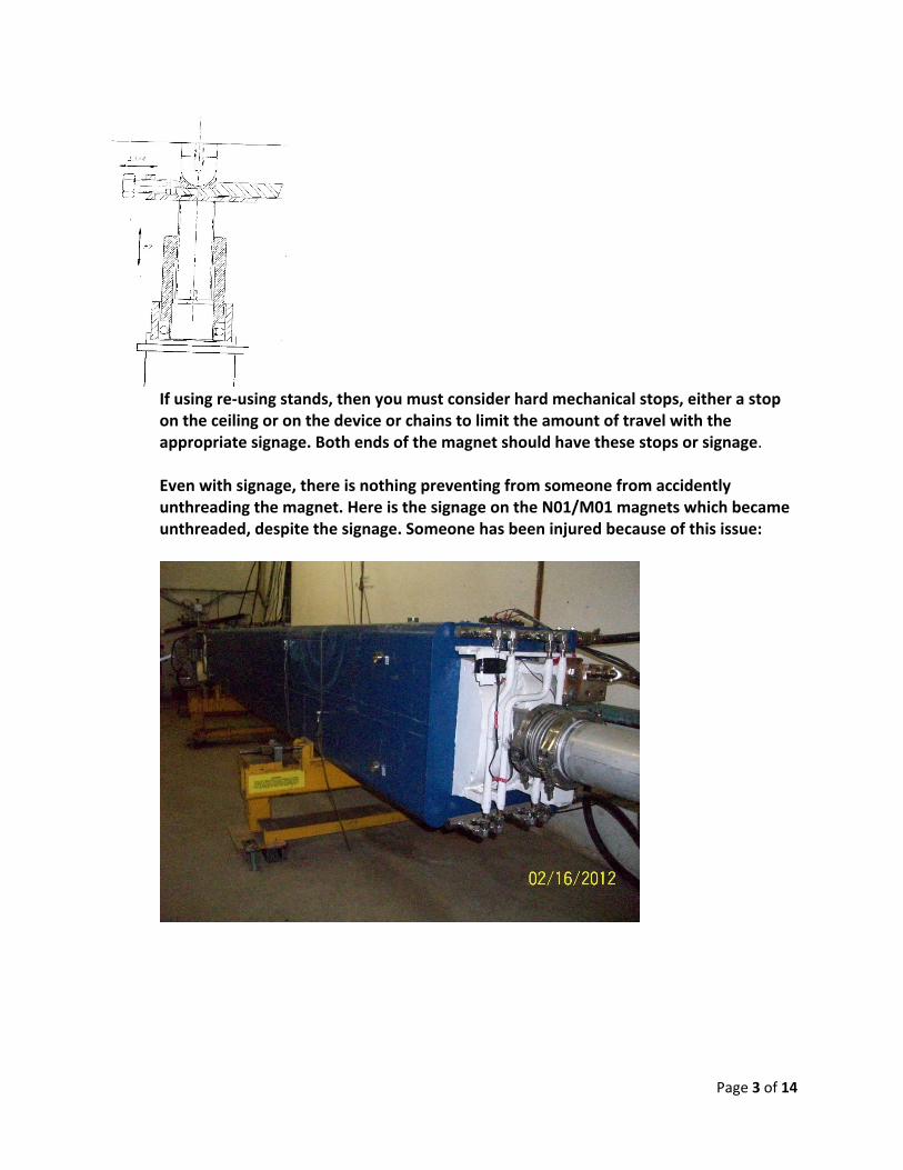
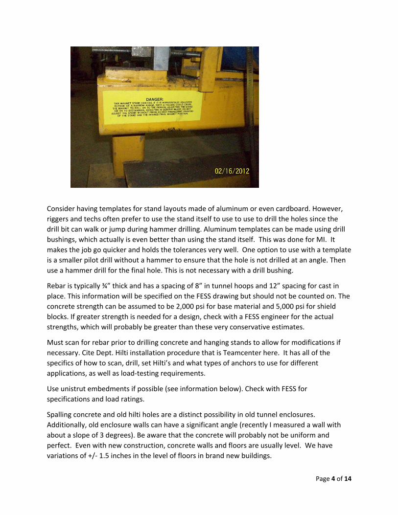
If using re‐using stands, then you must consider hard mechanical stops, either a stop on the ceiling or on the device or chains to limit the amount of travel with the appropriate signage. Both ends of the magnet should have these stops or signage. Even with signage, there is nothing preventing from someone from accidently unthreading the magnet. Here is the signage on the N01/M01 magnets which became unthreaded, despite the signage. Someone has been injured because of this issue:
Page 4 of 14
Consider having templates for stand layouts made of aluminum or even cardboard. However,
riggers and techs often prefer to use the stand itself to use to use to drill the holes since the
drill bit can walk or jump during hammer drilling. Aluminum templates can be made using drill
bushings, which actually is even better than using the stand itself. This was done for MI. It
makes the job go quicker and holds the tolerances very well. One option to use with a template
is a smaller pilot drill without a hammer to ensure that the hole is not drilled at an angle. Then
use a hammer drill for the final hole. This is not necessary with a drill bushing.
Rebar is typically ¾” thick and has a spacing of 8” in tunnel hoops and 12” spacing for cast in
place. This information will be specified on the FESS drawing but should not be counted on. The
concrete strength can be assumed to be 2,000 psi for base material and 5,000 psi for shield
blocks. If greater strength is needed for a design, check with a FESS engineer for the actual
strengths, which will probably be greater than these very conservative estimates.
Must scan for rebar prior to drilling concrete and hanging stands to allow for modifications if
necessary. Cite Dept. Hilti installation procedure that is Teamcenter here. It has all of the
specifics of how to scan, drill, set Hilti’s and what types of anchors to use for different
applications, as well as load‐testing requirements.
Use unistrut embedments if possible (see information below). Check with FESS for
specifications and load ratings.
Spalling concrete and old hilti holes are a distinct possibility in old tunnel enclosures.
Additionally, old enclosure walls can have a significant angle (recently I measured a wall with
about a slope of 3 degrees). Be aware that the concrete will probably not be uniform and
perfect. Even with new construction, concrete walls and floors are usually level. We have
variations of +/‐ 1.5 inches in the level of floors in brand new buildings.

Page 5 of 14
For ceiling stands, if possible, have extra holes for the Hilti’s. In that case, specify the minimum
number required or have the engineer consulted. Another option is to have pre‐drilled tabs
fabricated which can be welded on the stand if there are interference issues. Any stands that
get installed in ceiling, must meet the Hilti installation procedure requirements (refer to it again
here).
Holes in the stand feet should be far enough away from the upright verticals in order to get the
hilti hammer drill in (typically 2 to 3”). There is a 2” radius from the bit to the drill motor.
Slots should be perpendicular to the beam direction (only if the stand adjustability does not
account for this error, otherwise it is expensive to machine in slots in all stands). For ½” Hilti
drop‐ins, the holes should be 11/16”. For the ½” Hilti Kwik‐bolts, the holes should be 9/16”.
Vertical adjustment should either have a hard stop or provide that the end of threads should be visible.
For very tall stand, either the legs should be angled, or provide cross bracing, for structural truss
triangulation, as done on MiniBooNE B872 and Q874‐875.
For some installations, the magnet must be lifted and temporarily supported, then the stand moved into
place, then the magnet set on the stand. Provide clearance to move the stand in and out.
For magnets installed at a significant angle, provide angled fork adapters or other means of lifting the
magnet into place and removing it at an angle, as was done on Muon Abort ABV2.
For magnets installed by means of trolleys or rails or roller skates, provide that the installation rails are
structurally sound throughout the travel, and that the magnet can be set on and removed from the rail
system by fork lift or magnet mover or chain falls or hydraulic lift table, as was done on NUMI Q106.
If a magnet traps another magnet, provide that the first magnet can be removed and the supporting
members can be removed easily in order to change the second magnet, as was done on NUMI and ANU
extraction.
If a magnet spans a change in floor level, it is generally better to support the magnet on two stands, one
on each level, but provide the means to install this magnet, such as sideways moving rollers as was done
on Numi extraction.
For small stands, the base plate should be one unit or attached to each other in order to
maintain square‐ness and parallelism, as long as it does not create a binding situation.
Do not put 2 large magnets on one stand or tied on one stand. This was done for the B2
magnets for NuMI and were very difficult to align.
Consider how the magnet will be installed before finalizing the design. (mono‐rail, Hillman
rollers, Elwell, Rico Forklift, etc). Have assembly drawings which include installation steps
shown. This will help to mitigate installation interferences.
Consider whether there is a need for forklift lifting points or pads to be incorporated as a
permanent part of the stand. If so, measure the actual forks and do not rely on drawings.

Page 6 of 14
Concrete inserts:
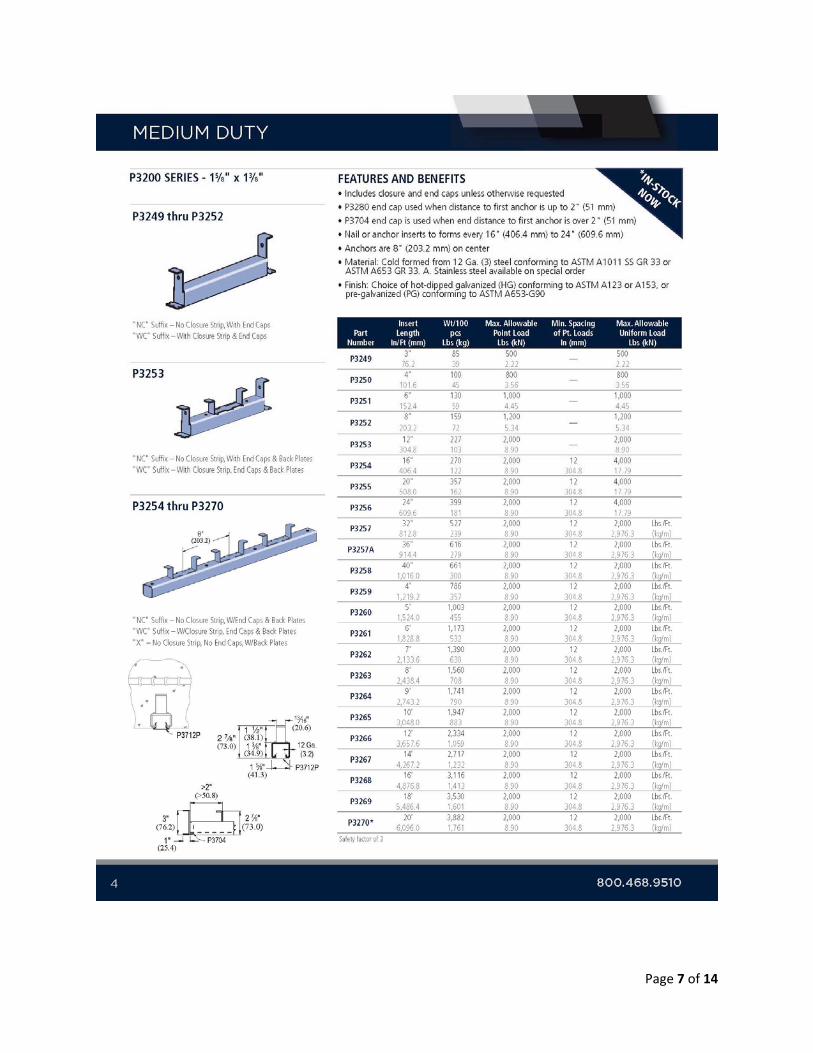
Below is a catalog cut indicating the capacity of Unistrut P3200 series concrete inserts.
As shown in attached data sheet, the allowable capacity for unistrut P3200 series inserts
varies depending on the continuous length of the embedment.
The Main Injector specified Unistrut P3200 series or Elcen Metal Products Figure 1150 concrete inserts in the general notes. I didn’t find any information for Elcen concrete inserts. The Elcen web site only has information for pipe hangers. That said, it is likely that the concrete inserts for Main Injector were Unistrut P3200 series. Unistrut P3200 series is also what our Mu2e drawings call for.
Page 7 of 14

Page 8 of 14
Mechanical Engineering Design and Analysis Guidelines Introduction
Stand designs are often re‐used within the Accelerator Complex and sometimes original (or unique)
designs are necessary. In either case, before proceeding with a design, initial stress calculations are
required. Primary stress and deflection estimates will indicate if a support is adequate or if reinforcement
is needed. Weldments are another important consideration regarding stress evaluation.
The basic characteristic of primary stress is that it is not self‐limiting, and failure, or at least gross
distortion, can occur from one application of the loading. Primary stress is stress caused by the
application of mechanical pressure, forces, and moments. Thermal stresses are not primary stresses.
Secondary stress is caused by the constraint of adjacent parts or by self‐constraint of the structure,
and yielding can cause the source of the stress to be eliminated. One load cycle can cause local yielding
and stress redistribution but cannot result in failure or gross distortion. This document focuses on the
primary stresses within the support design.
Allowable stress estimates for structural members, welds, and hardware are provided by the
American Institute of Steel Construction (AISC) Manual of Steel Construction, Allowable Stress Design1.
The maximum primary stress shall be less than 0.6Fy (in bending or tension), 0.4Fy (in shear), where the
Tensile Yield Strength (Fy) for A‐500 structural steel is 46 Ksi and for A‐36 steel it is 36 Ksi.
Stresses in Beams
Primary stresses within structures may be determined by considering a simple supported beam. This
is an effective way to initially understand the stresses present for a given design. As the design progresses,
a more detailed analysis may be considered which would include secondary stresses.
Normal Stress
A normal stress is a stress that occurs when a member is loaded by an axial force. The value of the
normal force for any prismatic section is simply the force divided by the cross sectional area:
A normal stress will occur when a member is placed in tension or compression. Examples of
members experiencing pure normal forces would include columns, collar ties, support rods, etc.

Page 9 of 14
When a member is being loaded similar to that in Figure 1, bending stress (or flexure stress) will
result. Bending stress is a more specific type of normal stress. When a beam experiences load as shown
in Figure 1, the top fibers of the beam undergo a normal compressive stress. The stress at the horizontal
plane of the neutral axis is zero. The bottom fibers of the beam undergo a normal tensile stress. It can
be concluded therefore that the value of the bending stress will vary linearly with distance from the
neutral axis.
Calculating the maximum bending stress is crucial for determining the adequacy of beams and longitudinal
girders and stand members.
Shear Stress
Normal stress is a result of load applied perpendicular to a member. Shear stress however results
when a load is applied parallel to an area. Figure 1 shows that both bending and shear stresses will
develop. As in bending stress, shear stress will vary across the cross sectional area.

Page 10 of 14
Calculating the maximum shear stress is crucial for determining the adequacy of beams and
longitudinal girders and stand members. Or simply = F/A, where F is the shearing force and A is the
cross‐sectional area.
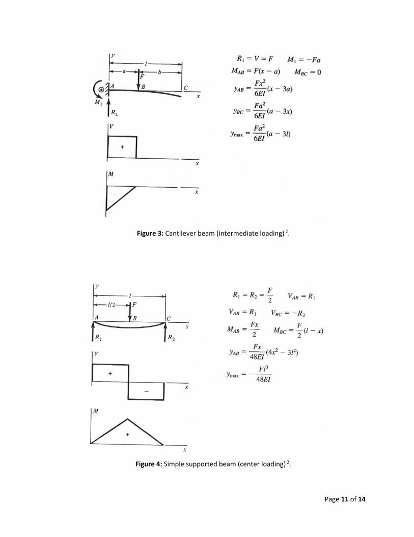
A few examples for different situations regarding beams is given in Figures 2, 3, 4 and 5 with the
relative equations needed to estimate reactions, moments and deflections.
Figure 2: Cantilever beam (end loading) 2.
Page 11 of 14
Figure 3: Cantilever beam (intermediate loading) 2.
Figure 4: Simple supported beam (center loading) 2.
Page 12 of 14
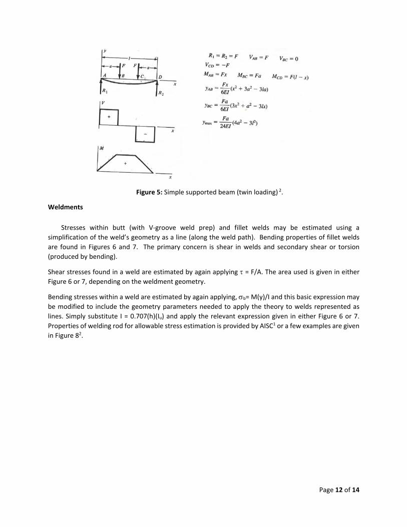
Figure 5: Simple supported beam (twin loading) 2.
Weldments
Stresses within butt (with V‐groove weld prep) and fillet welds may be estimated using a
simplification of the weld’s geometry as a line (along the weld path). Bending properties of fillet welds
are found in Figures 6 and 7. The primary concern is shear in welds and secondary shear or torsion
(produced by bending).
Shear stresses found in a weld are estimated by again applying = F/A. The area used is given in either Figure 6 or 7, depending on the weldment geometry.
Bending stresses within a weld are estimated by again applying, b= M(y)/I and this basic expression may
be modified to include the geometry parameters needed to apply the theory to welds represented as
lines. Simply substitute I = 0.707(h)(Iu) and apply the relevant expression given in either Figure 6 or 7.
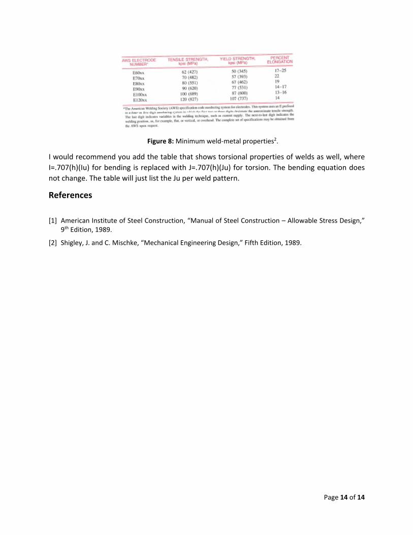
Properties of welding rod for allowable stress estimation is provided by AISC1 or a few examples are given
in Figure 82.

Page 13 of 14
Figure 6: Bending properties of fillet welds (part 1) 2.
Figure 7: Bending properties of fillet welds (part 2) 2.
Page 14 of 14
Figure 8: Minimum weld‐metal properties2.
I would recommend you add the table that shows torsional properties of welds as well, where
I=.707(h)(Iu) for bending is replaced with J=.707(h)(Ju) for torsion. The bending equation does
not change. The table will just list the Ju per weld pattern.
References
[1] American Institute of Steel Construction, “Manual of Steel Construction – Allowable Stress Design,” 9th Edition, 1989.
[2] Shigley, J. and C. Mischke, “Mechanical Engineering Design,” Fifth Edition, 1989.