student identification system
DESCRIPTION
a prject report on student identification system in dot netTRANSCRIPT

90
Chapter 1
INTRODUCTION ________________________________________________
90
1.1 PROJECT SUMMARY
A Student Identification System (SIS) for College/School Management
Information System (CMIS) is a System that manages the records of student regarding
admission and examination part.
A Student Identification System (SIS) is designed to help colleges for
management of student. Extensive information is available at your fingertips through this
System. Viewing student data, managing admission and reshuffling ,managing seats,
quota, board, semester, faculty, category and for examination, block allocation, subject
management , scheduling exam, result and related issues are made simple and easy. There
are custom search capabilities to aid in finding student information and working on student
records. This can make the system easier to navigate and to use maximizing the
effectiveness of time and other resources. SIS allows the keeping of personnel data in a
form that can be easily accessed and analyzed in a consistent way.
The SIS module is a component covering many other student aspects from
application to retirement. The system records basic personal information, admission
information, education information regarding student. Leading edge systems provide the
ability to "read" applications and enter relevant data to applicable database fields, notify
student and provide result. Student management function involves
Manage new admission and enrollment
Manage quota
Manage board
Manage category
Manage Fees Structure
Roll number generation
Fees payment
Student Basic Information
90
Manage faculty
Manage designation
Manage course and specialty
Manage semester and year
Admission seat management
Exam scheduling
Result management
Subject management
Block management
In SIS, every user has a Login ID and Password. Also all the users have different
permission rights to access the applications. These rights are Dynamic and can be
changed.
There are three main roles in the system. Admin, accountant and operator. Admin has
complete access to the whole system, while accountant is only concerned with payment of
fees for the admission of the student. Operator is the role that is responsible for the use of
the system.
The Admin role can be as follow:
Introduce new quota, board, category, course, etc
Set fees structures
Manage faculties
Manage subjects
Seat management
Management of semester
Generation of student roll number
Set examination
90
The operator role can:
New admission and enrollment
Search student
Block allocation
Result, etc
Now when the user with the particular role Logs on he can see only those pages which
are allowed to them.
1.2 PURPOSE
The project is about to handle all the information of the student regarding
admission and examination. Also it manages resources which were managed and handled
by manpower previously. The main purpose of the project is to integrate distinct sections
of the organization into consistent manner so that complex functions can be handled
smoothly by any technical or non-technical persons.
The project aims at the following matters:
Automation of admission and enrollment as per board, quota, category and available
seats.
Assistance in decision-making.
To manage information of student, faculty and courses.
Consistently update information of all the students.
Reports- To gather all the related information about any application of the HRMS.
All the above-mentioned matters are to be incorporated in the application along with some
additional requirements.
90
The main purpose of the Admin Module is to introduce new things and configure
important aspects. For e.g. only admin is authorized to introduce quota, board, subject,
category, etc. and only admin is allowed to configure exam and set fees structure. So the
master screens for all these are visible to only admin role. This is done by the Admin
Module. It also can create the users and Physical and Logical Locations. Thus the main
purpose of the Admin Module is to managing the dynamic working of the system.
1.3 SCOPE
The scope of the project includes the following
Any college can use this system as it is not client centric.
All admission and examination related work for the student can be done using this
system.
Deliver Electronic Workplace
Provide Bi-lingual support
Application Support & Maintenance after deployment to production
The Admin Module can be reused for projects as well which have many users with
different rights. Hence it is reusable.
1.4 TECHNOLOGY & LITERATURE REVIEW
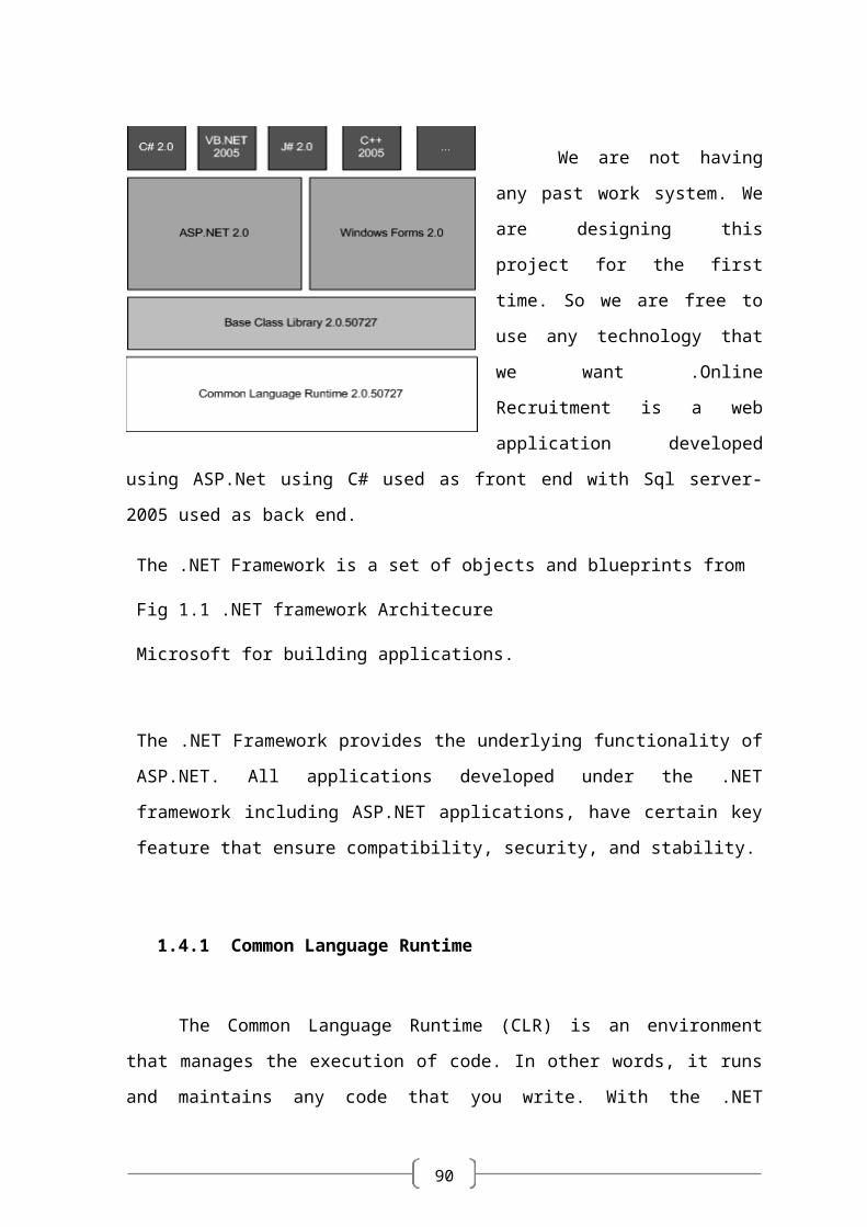
We are not having any past
work system. We are designing this
project for the first time. So we are
free to use any technology that we
want .Online Recruitment is a web
application developed using ASP.Net
using C# used as front end with Sql
server-2005 used as back end.
The .NET Framework is a set of
objects and blueprints from
Fig 1.1 .NET framework Architecure
90
Microsoft for building applications.
The .NET Framework provides the underlying functionality of ASP.NET. All
applications developed under the .NET framework including ASP.NET applications,
have certain key feature that ensure compatibility, security, and stability.
1.4.1 Common Language Runtime
The Common Language Runtime (CLR) is an environment that manages the
execution of code. In other words, it runs and maintains any code that you write. With
the .NET framework and CLR you still write code and compile it. However, instead of
compiling it into something that computer understands, you compile it into a language
called the Microsoft Intermediate Language (MSIL). This language is shorthand way of
representing all the code you have written. ASP.NET pages are compiled into MSIL as
well. When you compile to MSIL, your application produces something called metadata.
This is descriptive information about your application. It tells what the application can do,
where it belongs, and so on.
1.4.2 Introduction about ASP.NET
ASP.NET, the latest version of Active Server Pages, is Microsoft’s technology for
building dynamic pages, database-driven Web sites. Active Server Pages is one of the
most popular languages for building scalable, interactive Web sites. Several of the highest
traffic Web sites on the Internet employs Active Server Pages. Examples include Dell
Online, Barnes and Noble, 1-800-flowers, and the Microsoft site itself.
1.4.2.1 Easy Programming Model
ASP.NET makes building real world Web applications dramatically easier.
ASP.NET server controls enable an HTML-like style of declarative programming that let
90
you build great pages with far less code than with classic ASP. Displaying data, validating
user input, and uploading files are all amazingly easy. Best of all, ASP.NET pages work
in all browsers -- including Netscape, Opera, AOL, and Internet Explorer.
1.4.2.2 Flexible Language Options
ASP.NET lets you leverage your current programming language skills. Unlike
classic ASP, which supports only interpreted VBScript and JScript, ASP.NET now
supports more than 25 .NET languages (including built-in support for VB.NET, C#, and
JScript.NET -- no tool required), giving you unprecedented flexibility in your choice
of language.
1.4.2.3 Great Tool Support
You can harness the full power of ASP.NET using any text editor
-- even Notepad! But Visual Studio 2008 adds the productivity of Visual Basic-style
development to the Web. Now you can visually design ASP.NET Web Forms using
familiar drag-drop-double-click techniques, and enjoy full-fledged code support including
statement completion and color-coding. VS.NET also provides integrated support for
debugging and deploying ASP.NET Web applications.
The Professional version of Visual Studio 2008 delivers life-cycle features to help
organizations plan, analyze, design, build, test, and coordinate teams that develop
ASP.NET Web applications. These include UML class modeling, database modeling
(conceptual, logical, and physical models), testing tools (functional, performance and
scalability), and enterprise frameworks and templates, all available within the integrated
Visual Studio .NET environment.
90
1.4.2.4 Rich Class Framework
Application features that used to be hard to implement, or required a 3rd-party
component, can now be added in just a few lines of code using the .NET Framework.
The .NET Framework offers over 4500 classes that encapsulate rich functionality like
XML, data access, file upload, regular expressions, image generation, performance
monitoring and logging, transactions, message queuing, SMTP mail, and much more!
1.4.2.5 Compiled execution
ASP.NET is much faster than classic ASP, while preserving the "just hit save"
update model of ASP. However, no explicit compile step is required! ASP.NET will
automatically detect any changes, dynamically compile the files if needed, and store the
compiled results to reuse for subsequent requests. Dynamic compilation ensures that your
application is always up to date, and compiled execution makes it fast.
1.4.2.6 Rich output caching
ASP.NET output caching can dramatically improve the performance and
scalability of your application. When output caching is enabled on a page, ASP.NET
executes the page just once, and saves the result in memory in addition to sending it to the
user. When another user requests the same page, ASP.NET serves the cached result from
memory without re-executing the page. Output caching is configurable, and can be used
to cache individual regions or an entire page. Output caching can dramatically improve
the performance of data-driven pages by eliminating the need to query the database on
every request.
90
1.4.2.7 Web-Farm Session State0
ASP.NET session state lets you share session data user-specific state values across
all machines in your Web farm. Now a user can hit different servers in the web farm over
multiple requests and still have full access to her session. And since business components
created with the .NET Framework are free-threaded, you no longer need to worry about
thread affinity.
1.4.2.8 Memory Leak, DeadLock and Crash Protection
ASP.NET automatically detects and recovers from errors like deadlocks and
memory leaks to ensure your application is always available to your users.
For example, say that your application has a small memory leak, and that after a week the
leak has tied up a significant percentage of your server's virtual memory. ASP.NET will
detect this condition, automatically start up another copy of the ASP.NET worker process,
and direct all new requests to the new process. Once the old process has finished
processing its pending requests, it is gracefully disposed and the leaked memory is
released. Automatically, without administrator intervention or any interruption of service,
ASP.NET has recovered from the error.
1.4.2.9 Dynamic update of running application
ASP.NET now lets you update compiled components without restarting the web
server. In the past with classic COM components, the developer would have to restart the
web server each time he deployed an update. With ASP.NET, you simply copy the
component over the existing DLL -- ASP.NET will automatically detect the change and
start using the new code.
90
1.4.3 Architecture Used/Followed (4-TIER ARCHITECTURE)
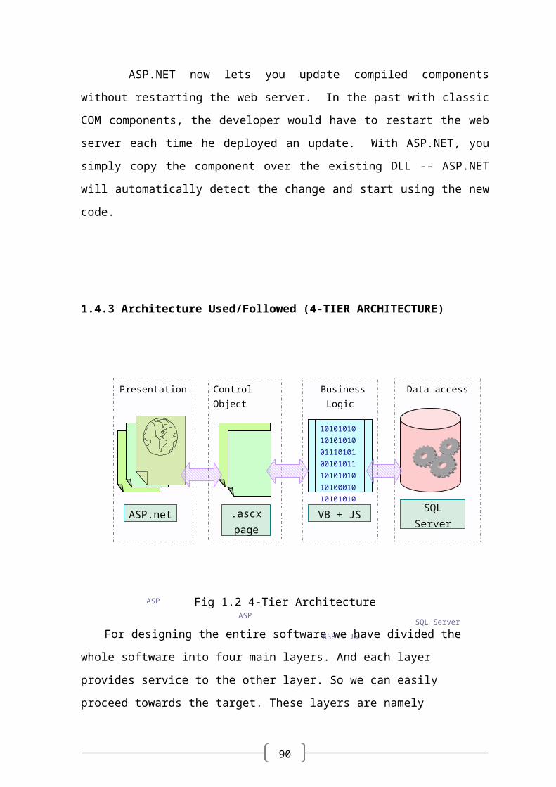
Fig 1.2 4-Tier Architecture
For designing the entire software we have divided the whole software into four main
layers. And each layer provides service to the other layer. So we can easily proceed
towards the target. These layers are namely
Presentation layer
Business layer
Control layer
Data Access layer
Presentation Layer
The Presentation layer is responsible for the user interface and communicates
directly with the business logic layer. Separating the presentation layer from the rest of the
application enables the development of different user interface (i.e. Web form, Windows
form, mobile devices) that all uses the same business logic and database access code.
Business Layer
Presentation
ASP
ASP.net SQL Server
Control Object
ASP
Data access
SQL Server
.ascx page
1010101010101010011101010010101110101010101000101010101010011110
VB + JS
Business Logic
ASP + JS
90
The logic layer separates the code specific to the application, for the way company
does the business, from the user interface and the database specific code. Other line of
business Applications a company build can use the business logic layer if needed,
maximizing the code reuse.
Control Layer
The Control layer is responsible for communication between business layer and
presentation layer. It connects the logic and data with each other and gives a better
connectivity and separation between layers.
Data Access Layer
Project Flow Lines and Artificial Lift use a Microsoft SQL Server Express
Edition database.
90
Chapter 2
PROJECT MANAGEMENT ________________________________________________
90
2.1 PROJECT PLANNING AND SCHEDULING
Project planning is part of project management, which relates to the use of
schedules such as Gantt charts to plan and subsequently report progress within the
project environment. Initially, the project scope is defined and the appropriate methods
for completing the project are determined. Following this step, the durations for the
various tasks necessary to complete the work are listed and grouped into a work
breakdown structure. The logical dependencies between tasks are defined using an
activity network diagram that enables identification of the critical path. Float or slack
time in the schedule can be calculated using project management software. Then the
necessary resources can be estimated and costs for each activity can be allocated to each
resource, giving the total project cost. At this stage, the project plan may be optimized to
achieve the appropriate balance between resource usage and project duration to comply
with the project objectives. Once established and agreed, the plan becomes what is
known as the baseline. Progress will be measured against the baseline throughout the life
of the project. Analyzing progress compared to the baseline is known as earned value
management
2.1.1 Project Development Approach
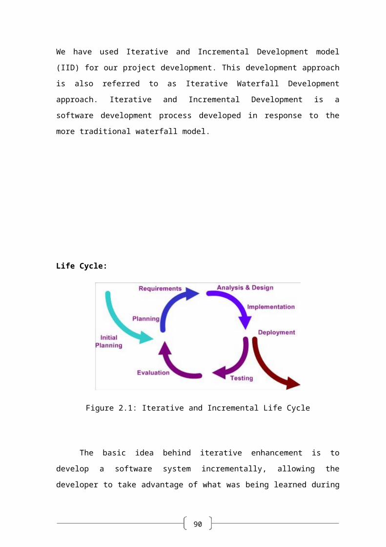
We have used Iterative and Incremental Development model (IID) for our project
development. This development approach is also referred to as Iterative Waterfall
Development approach. Iterative and Incremental Development is a software development
process developed in response to the more traditional waterfall model.
90
Life Cycle:
Figure 2.1: Iterative and Incremental Life Cycle
The basic idea behind iterative enhancement is to develop a software system
incrementally, allowing the developer to take advantage of what was being learned during
the development of earlier, incremental, deliverable versions of the system. Learning
comes from both the development and use of the system, where possible. Key steps in the
process were to start with a simple implementation of a subset of the software
requirements and iteratively enhance the evolving sequence of versions until the full
system is implemented.
At each iteration, the procedure itself consists of the Initialization step, the
Iteration step, and the Project Control List. The initialization step creates a base version of
the system. The goal for this initial implementation is to create a product to which the user
can react. It should offer a sampling of the key aspects of the problem and provide a
solution that is simple enough to understand and implement easily. To guide the iteration
process, a project control list is created that contains a record of all tasks that need to be
performed. It includes such items as new features to be implemented and areas of redesign
of the existing solution. The control list is constantly being revised as a result of the
analysis phase.
90
The iteration involves the redesign and implementation of a task from project
control list, and the analysis of the current version of the system. The goal for the design
and implementation of any iteration is to be simple, straightforward, and modular,
supporting redesign at that stage or as a task added to the project control list. The code
can, in some cases, represent the major source of documentation of the system. The
analysis of an iteration is based upon user feedback, and the program analysis facilities
available. It involves analysis of the structure, modularity, usability, reliability, efficiency,
and achievement of goals. The project control list is modified in light of the analysis
results.
During the implementation of the project by this approach, a step called V&V i.e.
Verification and Validation is carried out at certain intervals.
Verification: “Are we building the product right?”
Validation: “Are we building the right product?”
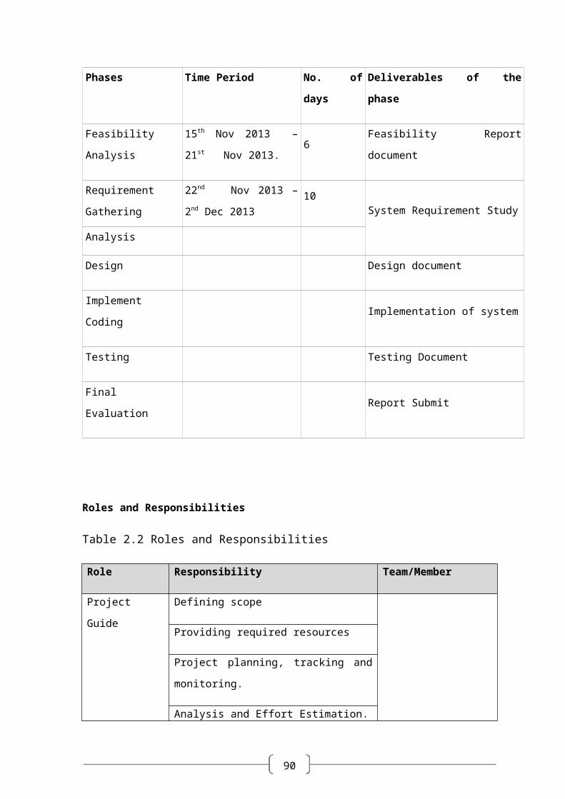
2.1.2 Project Plan
Once we examine that the project is feasible, we undertake project planning. The table below
describes how we planned our project.
Table 2.1 Project Plan
Phases Time Period No. of days Deliverables of the phase
Feasibility Analysis15th Nov 2013 – 21st
Nov 2013.6 Feasibility Report document
Requirement
Gathering
22nd Nov 2013 – 2nd Dec
201310
System Requirement Study
Analysis
Design Design document

90
Phases Time Period No. of days Deliverables of the phase
Implement Coding Implementation of system
Testing Testing Document
Final Evaluation Report Submit
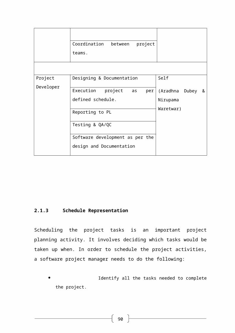
Roles and Responsibilities
Table 2.2 Roles and Responsibilities
Role Responsibility Team/Member
Project Guide Defining scope
Providing required resources
Project planning, tracking and monitoring.
Analysis and Effort Estimation.
Coordination between project teams.
Project Developer Designing & Documentation Self
(Aradhna Dubey &
Nirupama Waretwar)
Execution project as per defined schedule.
Reporting to PL
Testing & QA/QC
Software development as per the design and
Documentation
90
2.1.3 Schedule Representation
Scheduling the project tasks is an important project planning activity. It involves deciding
which tasks would be taken up when. In order to schedule the project activities, a software
project manager needs to do the following:
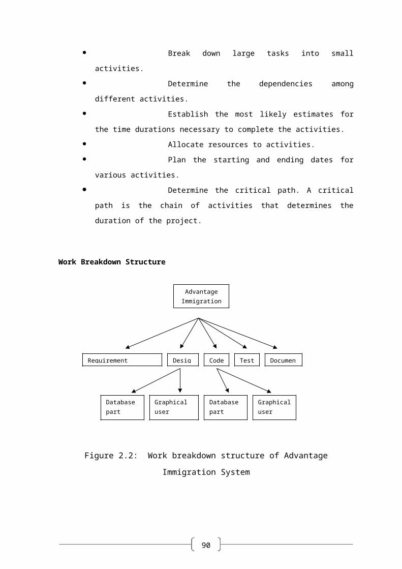
Identify all the tasks needed to complete the project.
Break down large tasks into small activities.
Determine the dependencies among different activities.
Establish the most likely estimates for the time durations
necessary to complete the activities.
Allocate resources to activities.
Plan the starting and ending dates for various activities.
Determine the critical path. A critical path is the chain of
activities that determines the duration of the project.
Work Breakdown Structure
Figure 2.2: Work breakdown structure of Advantage Immigration System
Advantage Immigration
Requirement Specification Design Code Test Document
Database part
Graphical user interface part
Database part
Graphical user interface
90
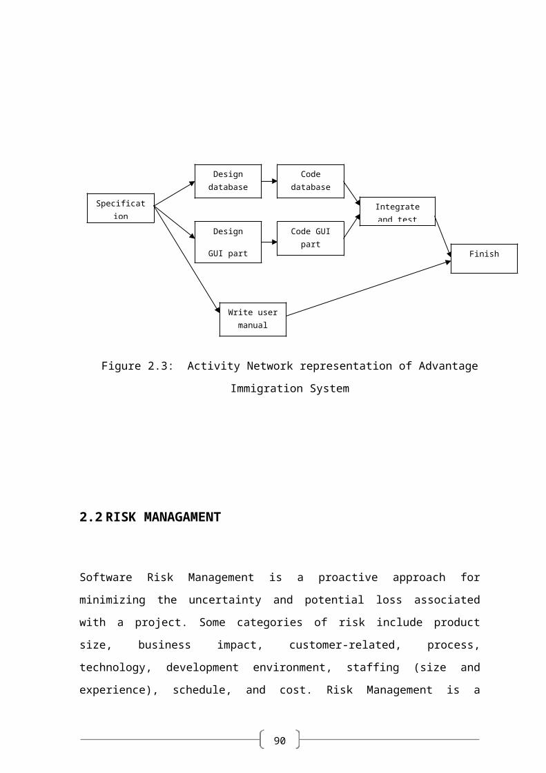
Figure 2.3: Activity Network representation of Advantage Immigration System
2.2 RISK MANAGAMENT
Software Risk Management is a proactive approach for minimizing the uncertainty and
potential loss associated with a project. Some categories of risk include product size,
business impact, customer-related, process, technology, development environment,
staffing (size and experience), schedule, and cost. Risk Management is a practice with
processes, methods, and tools for managing risks in a project. It provides a disciplined
environment for proactive decision making to
Assess continuously what could go wrong (risks)
Determine which risks are important to deal with
Implement strategies to deal with those risks
2.2.1 Risk Identification
Specification
Design database part
Integrate and test
Code database part
Write user manual
Finish
Code GUI partDesign
GUI part
90
Risk identification is a systematic attempt to specify threats to the project plan. By
identifying known and predictable risks, we can take a first step toward avoiding them
when possible and controlling them when necessary. To perform the risk identification, we
categorized the risk into different categories as:
A. Project Risk
B. Technical Risk
C. Business Risk
D. Known Risk
E. Predictable Risk
F. Unpredictable Risk
A. Project Risk:
The Project Risk threatens the project plan. The project risks here are:
A1. Schedule slippage.
A2. Incomplete requirement specification.
A3. Change in user Requirements.
A4. Non-availability of required resources.
A5. Lack of communication with end user.
A6. Improper vision about the project.
A7. Staffing and organization problems.
A8. Non-technical customer with high technical expectations.
B. Technical Risk:
The Technical Risk threatens the quality and timeliness of the software to be produced.
If the technical risk becomes a reality, implementation may become difficult or
impossible. The technical risks identified in our project are:
B1. Unavailable library files.
B2. Problem in connection to database server.
90
B3. Problem in application server.
B4. Problem in browser view.
C. Business Risk:
The Business Risk threatens the viability of the software to be built.
C1. Project not delivered on time.
C2. Switching of database structure.
D. Predictable Risk:
The Predictable risks are extrapolated from past project experience. Since we have not
done any live industry project during the academic years, the predictable risks were very
few. The predictable risk include mainly:
D1. Language error predictions.
D2. Lack of End user support in future project enhancement.
E. Unpredictable Risk
The Unpredictable risks are the joker in the deck. They can and do occur, but they are
extremely difficult to identify in advance.
2.2.2 Risk Analysis
Each identified risk is considered and the effect and probability of each risk is identified
during risk analysis.
2.2.3 Risk Planning
Risk planning lists the checkpoints that are made continually to find out situation where the risk
can becomes reality.
Plan entire schedule on paper in the beginning and follow it.
90
Understand the scope from external guide to have the correct
design.
Find out proper documentation, manuals and guides from the
person having the required knowledge.
Schedule should not be delayed too much.
Take backups regularly.
Perform thorough requirement gathering and analysis.
Confirm the collected requirements with the guide.
2.3 ESTIMATION
The estimation of various project parameters is a basic project planning activity. The
important project parameters that are estimated include: project size, effort required to
develop the software, project duration and cost. These estimates not only help in quoting
the project cost to the customer, but also prove useful in resource planning and scheduling.
There are three broad categories of estimation techniques:
Empirical estimation techniques
Heuristic techniques
Analytical estimation techniques
COCOMO (Constructive Cost estimation Model) – Heuristic technique
The basic COCOMO model gives an approximate estimate of the project parameters. The basic
COCOMO estimation model is given by the following expressions:
Effort = a1 * (KLOC) a2 PM
Tdev = b1 * (Effort) b2 months
Where a1, a2, b1, b2 are constants for each category of software process. KLOC is the estimated
size of product in Kilo Lines of Code. Tdev is the estimated time to develop the software,
90
expressed in months. Effort is the total effort required to develop the software product, expressed
in person month.
The COMOMO model estimation can be classified into three categories
Organic
Semidetached
Embedded
2.3.1 Effort estimation
We followed the most common and feasible approach for estimating the effort required in
the software development in which project size is variable and the equation of the effort is
given by
EFFORT = a * SIZE b.
According to the survey and analysis carried out at IBM Federal System Division, if the
size estimate is in KDLOC and the project is ranging from 4000 to 467000 lines of
delivered source code then the equation for total effort, E, in person months (PM) can be
given by
E = 4.1 * 5 0.7 = 12.64 PM.
Where 3.2 and 0.7 are values of a and b determined depending upon the data about the
projects that has been performed in the past.
2.3.2 Duration estimation
As mentioned earlier we used the survey and analysis results given by IBM Federal System
Division and according to those results the total duration, D , in calendar months can be estimated
by the equation
D = a * E b.
90
Again determining the values of a and b from the data about the projects that has been performed
in the past we get the equation
D = 2.3 * 12.64 0. 38 = 6.03 Months.
Chapter 3
90
SYSTEM REQUIREMENT STUDY ________________________________________________
3.1 USER CHARACTERISTICS
90
Administrator:
The administrator has all the rights to access the system. He is the one who has all rights to
view the applicant details, modify those details, The administrator also keeps a track of the
file status of the applicants.
User :
Applicant is the one who wish to visit SIS website. The applicant can fill in his own
details and register himself for membership to use portal services. The applicant has rights
to view and modify his own details, generate its candidature of containing his own details
in academic web part. The applicant also rights to create groups, modify groups, invite
member, modify member, join group, slam book requests, etc. In sort, the applicant can
access the application like a moderator of his/her group.
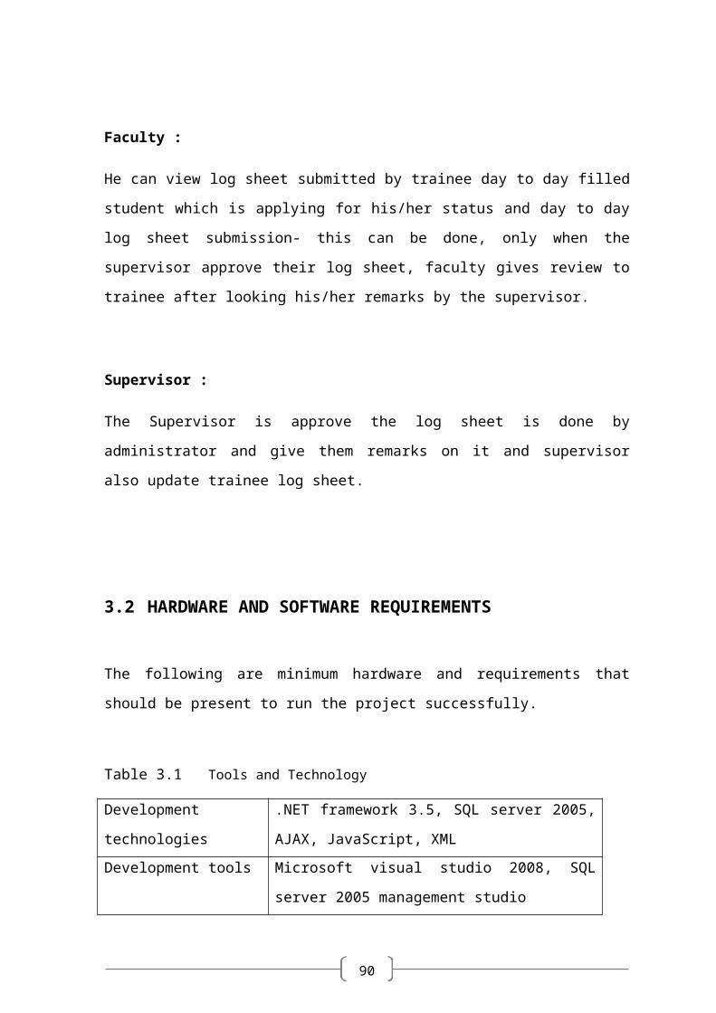
Faculty :
He can view log sheet submitted by trainee day to day filled student which is applying for
his/her status and day to day log sheet submission- this can be done, only when the
supervisor approve their log sheet, faculty gives review to trainee after looking his/her
remarks by the supervisor.
Supervisor :
The Supervisor is approve the log sheet is done by administrator and give them remarks on
it and supervisor also update trainee log sheet.
3.2 HARDWARE AND SOFTWARE REQUIREMENTS
90
The following are minimum hardware and requirements that should be present to run the
project successfully.
Table 3.1 Tools and Technology
Development technologies .NET framework 3.5, SQL server 2005, AJAX,
JavaScript, XML
Development tools Microsoft visual studio 2008, SQL server 2005
management studio
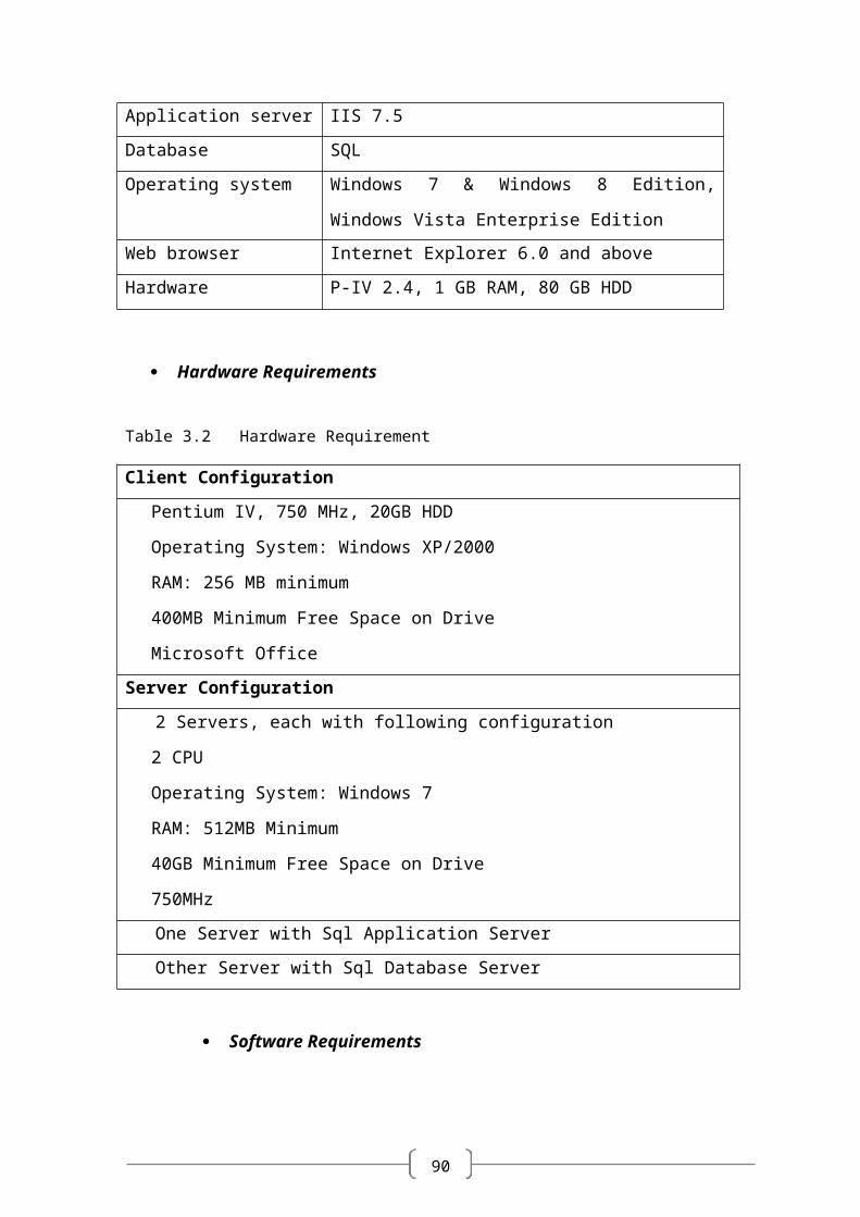
Application server IIS 7.5
Database SQL
Operating system Windows 7 & Windows 8 Edition, Windows Vista
Enterprise Edition
Web browser Internet Explorer 6.0 and above
Hardware P-IV 2.4, 1 GB RAM, 80 GB HDD
Hardware Requirements
Table 3.2 Hardware Requirement
Client Configuration
Pentium IV, 750 MHz, 20GB HDD
Operating System: Windows XP/2000
RAM: 256 MB minimum
400MB Minimum Free Space on Drive
Microsoft Office
Server Configuration
2 Servers, each with following configuration
2 CPU
Operating System: Windows 7
RAM: 512MB Minimum
40GB Minimum Free Space on Drive
90
750MHz
One Server with Sql Application Server
Other Server with Sql Database Server
Software Requirements
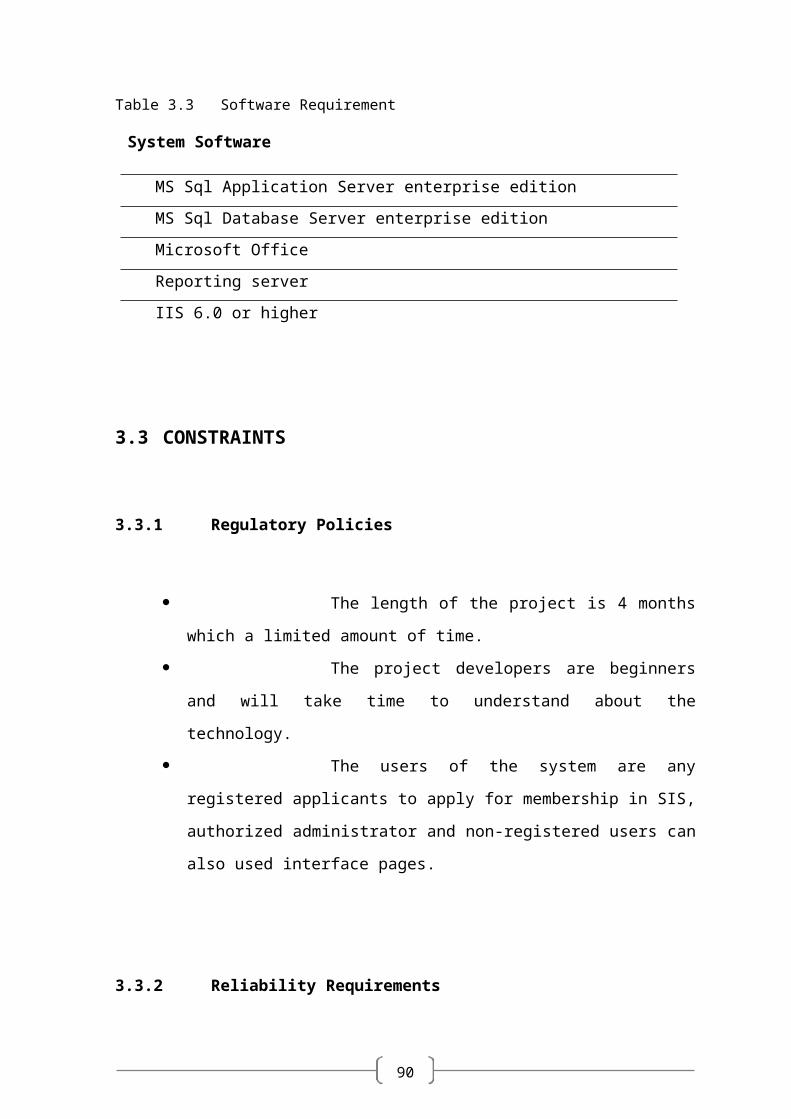
Table 3.3 Software Requirement
System Software
MS Sql Application Server enterprise edition
MS Sql Database Server enterprise edition
Microsoft Office
Reporting server
IIS 6.0 or higher
3.3 CONSTRAINTS
3.3.1 Regulatory Policies
The length of the project is 4 months which a limited
amount of time.
The project developers are beginners and will take time
to understand about the technology.
The users of the system are any registered applicants to
apply for membership in SIS, authorized administrator and non-registered users
can also used interface pages.
3.3.2 Reliability Requirements
90
The system should be reliable enough so that the data
found in the database system is consistent at any point.
The system should be able to handle loads of requests
from different users around the world at the same time.
3.3.3 Criticality Of The Application
The system is a web-based application and so fails to
work if there is no Internet connection. The system might not work if the
Internet connection slows down.
The system stops working in case if the database server
or the application server stops working.
The system might give erroneous output if it fails to
connect to the database server.
3.3.4 Safety and Security Considerations
The Intranet password security
Each applicant is given a login account through which he
can view his own information and also modify and save it. He has the rights to
access only his own information.
The administrator has rights through which he can
access and manage whole system.
The password is encrypted before it is sent over the
network. This increases the security level.
SQL Server 2005 provides greater security to the
database.
Chapter 4
90
SYSTEM ANALYSIS ________________________________________________
4.1 STUDY OF CURRENT SYSTEM
90
The current system for the Student Management System deals with maintaining a
physical contact with the academy management dept. for filling all the details and the
documentation work. The management doesn’t needs to visit the academy management
dept. and collect the assignment and submitting his/her documents directly.
According to the current system, the management has to fill in the forms manually,
go to the account management dept., and submit him the form. The applicant needs to visit
the academy portal now and then in order to get his work accomplished. The admin also
has to manage all the users. He needs to maintain records of all the users, their activity
status, submission methods and installation details on paper. The Manual process is more
error prone and also slow. Moreover Students in the academy can interface his/her work
area only. But if an online application is available then they can communicate whole
system. Thus a simulation of this entire process can be a boon to the applicants as well as
the admin.
4.2 PROBLEMS AND WEAKNESSES OF CURRENT SYSTEM
The present system has certain major disadvantages. A few to be listed can be
excessive paperwork, time consuming process flow, laborious work environment
for employees, difficulty to access historical data and all these problems lead to
inefficient working of government sector causing dissatisfaction in the general
public.
Apart from the above stated problems there is lack of transparency in the existing
system. This being one of the major drawbacks in the system needs special
attention.
The problem stated above have certain deep rooted problems like time consuming
process flow for which the government may need to change the structure of the
process flow in certain cases so that the system output can become faster.
The following listed are the problems or weaknesses of the current system:

90
So much time consume in preparing registers which is having replicated
data
It is difficult to prepare report for decision making.
Attendance related module is not there.
4.3 REQUIREMETNS OF NEW SYSTEM
4.3.1 User Requirements
R1: login
Actor: Admin, Operator, Accountant
Pre Condition: None
Input: User Id and Password
Output: Home Page as per role
Flow:
(1) User Logs in with username and password.
(2) If correct then Home Page is displayed.
Alternate Flow:
(1) If the username is wrong then it is asked to login again.
(2) If the password is wrong then the user is asked to enter again.
R2: Pay fees
Actor: Accountant
Pre Condition: User must be logged on
Input: Student ID
Output: Fees paid
90
Flow:
(1) Accountant enters student ID
(2) Details of student is shown with the status of fees paid or not.
(3) If fees not paid then Accountant collects the fees.
(4) student can get the print receipt of paid fees.
Alternate Flow:
(1) If the fields marked with ‘*’ are empty then alert is displayed.
(2) If student ID does not exist then the system alerts it.
R3: Get admission
Actor: operator
Pre Condition: User must be logged on
Input: Complete Details of the student including personal, academic records.
Output: Student ID is generated and student is admitted.
Flow:
(1) Admin clicks on ‘New admission’ link
(2) New generated Student ID is displayed.
(3) Details of student is filled in the form by operator.
(4) Newly generated ID is given to student.
(5) The student is admitted to the particular course.
Alternate Flow:
(1) If the mandatory fields are not filled then alert is shown.
(2) If there is no available seat for the particular admission then alert is shown.

90
R4: Enrolment
Actor: operator
Pre Condition: User must be logged on and student has already got admission.
Input: Details for the enrolment of the student.
Output: student has got enrolment.
Flow:
(1) Admin selects the “enrolment” link.
(2) Then he enter the student ID.
(3) Details that is applicable to the student for the enrolment is shown.
(4) student is enrolled to the next year or semester.
Alternate Flow:
(1) If student has not passed last semester then system alerts.
R5: Modify student Details
Actor: operator
Pre Condition: User must be logged on
Input: student ID
Output: The changes as per modification of the student details in DB
Flow:
(1) Operator selects the link from the list.
(2) Then he enters the ID of the student to be modified.
(3) Then he modifies the details as required.
(4) Then he submits to effect the changes.
Alternate Flow:
(1) If the user clicks the ‘Cancel’ button, then no changes are reflected in the DB.
90
4.3.2 System Requirements
Registration details of the applicant.
Login details of the applicant.
Personal details of the applicant.
Information of all the members of the applicant’s group.
Information of all the friend list of the applicant’s
account.
Educational and employment information
All information and rules regarding the e-forms must
follow.
Certain legal details of the applicant.
Details regarding the purpose of user visit to academy.
The statutory declaration of the applicant.
Answers to the questionnaire for skill assessment of
visitor.
Communication with whole system.
4.3.3 Non-Functional Requirements
Usability
The interface should use terms and concepts, which are drawn from the
experience of the people who will make most of the system. For example,
map and date should be displayed in its traditional fashion.
Efficiency
The system must provide easy and fast access without consuming more
cost.
90
Reliability
User should never be surprised by the behaviour of the system and it should
also provide meaningful feedback when errors occur so that user can
recover from the errors.
4.4 FEASIBILITY STUDY
The aim of the feasibility study activity is to determine whether it would be
financially and technically feasible to develop the system or not. A feasibility study is
carried out from following different aspects:
Operational Feasibility:
The system has been developed for any user who wants to use this system. We have
given a demo of our project and the users found the system friendly and easy to use. The
interoperability with the existing system is also checked after uploading the website. So
they may face certain problems in using the user interface. So keeping this consideration
in mind we have provided field for each and every field on the forms. The administrator
also may be non-technical, so the user interface is designed in such a way that it gets
comfortable for the non-technical person to operate easily.
Technical Feasibility:
It determines if the system can be implemented using the current technology. This
system has been developed using asp.net (VB) as front end and SQL Server 2005 as
backend. Though the MVS 2008 technology was new to us it was not so difficult for us to
learn it. This was also new to us but it didn’t take much effort and time to get used to it.
90
We had earlier worked with Access and not SQL Server 2005 but getting familiar with it
was also easy.
Economical Feasibility:
The company being a well-to-do company didn’t have any problem in buying any
software that was required in developing the application. The software’s we used were
readily available. So as such we didn’t face any economical constrains.
Implementation Feasibility:
This project can easily be made available online without much consideration of the
hardware and software. The only required thing at the applicant’s side is the Internet
connection and a web browser, which are a no difficult issue these days. A database server
and application server are required to set up at the admin side. After setting up the project
online, even the administrator can access the system from anywhere.
4.5 REQUIREMENTS VALIDATION
Requirement Validation examines the specification to ensure that all system
requirements have been stated unambiguously; those inconsistencies, errors have been
detected and corrected and the work products conform to the standard.
Source of the requirements are identified. Final
statement of requirement has been examined by original source.
Requirements related to main requirements are found.
Requirements are testable.
90
Requirements are clearly stated and are not
misinterpreted.
All sources of requirements are covered to get maximum
requirement.
All methods of finding requirements are applied.
Requirements are not duplicated and each of them gives
distinct idea of processes within project.
Requirement associated with system performance,
behavioural and operational characteristics are clearly stated.
Requirements are being discussed with the client in
order to remove the misinterpretations if they exist.
Each requirement is being analyzed to prove its
feasibility for the current system.
4.6 FUNCTIONS OF SYSTEM
4.6.1 Use Case
The use case model for any system consists of a set if “use cases”. Intuitively, use
cases represent the different ways in which the users can use a system. Following is the
use case representation of the advantage immigration system.
90
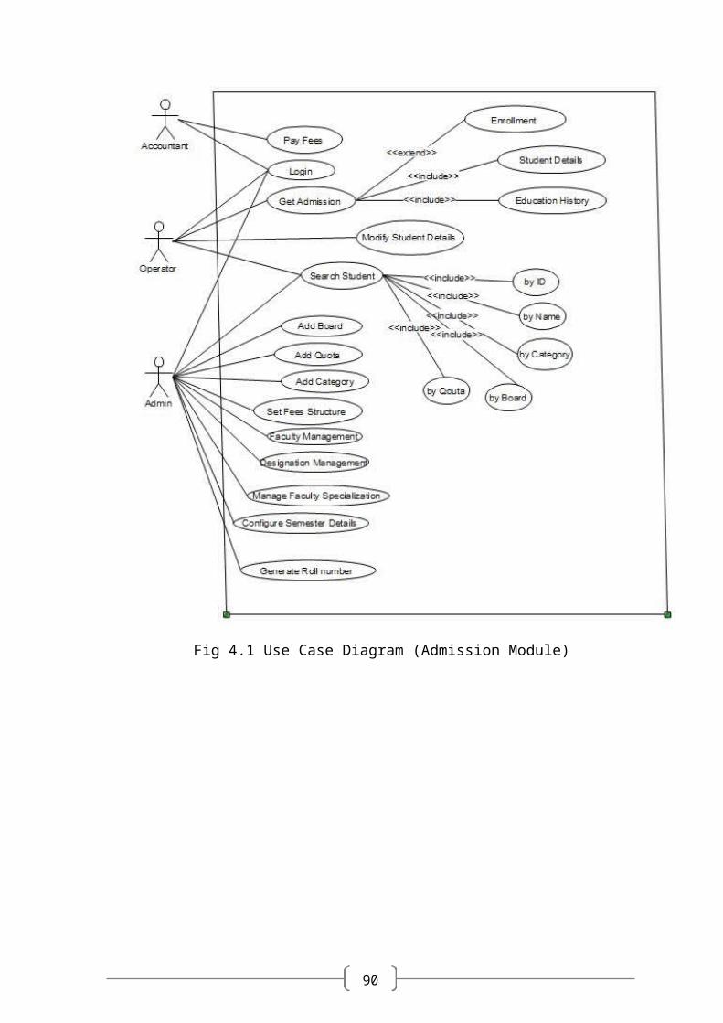
Fig 4.1 Use Case Diagram (Admission Module)
90
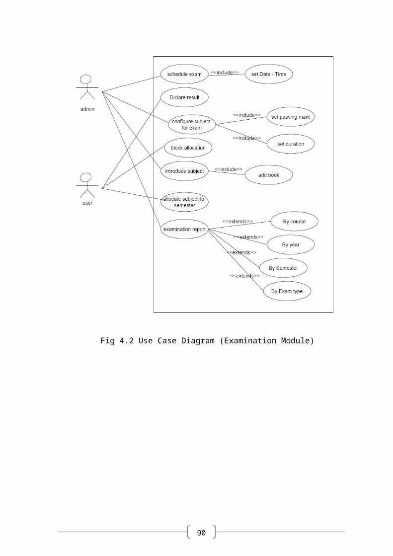
Fig 4.2 Use Case Diagram (Examination Module)
90
4.7 DATA MODELING
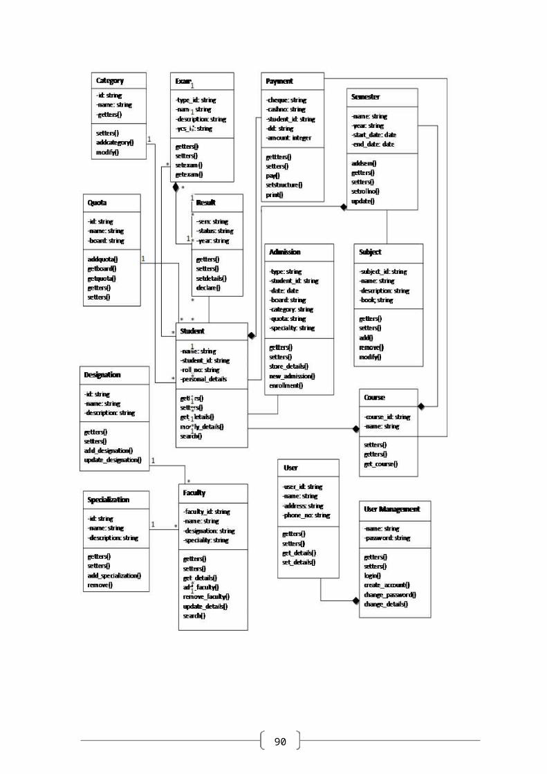
4.7.1 Class Diagram
A class diagram describes the static structure of a system. It shows how a system is
structured rather than how it behaves. The static structure of a system consists of a number
of class diagrams and their dependencies. The main constituents of a class diagram are
classes and their relationships: generalization, aggregation, association, and various kinds
of dependencies.
Following diagram represents various classes of the system. The relations between
these classes are shown in the next diagram.
90
90
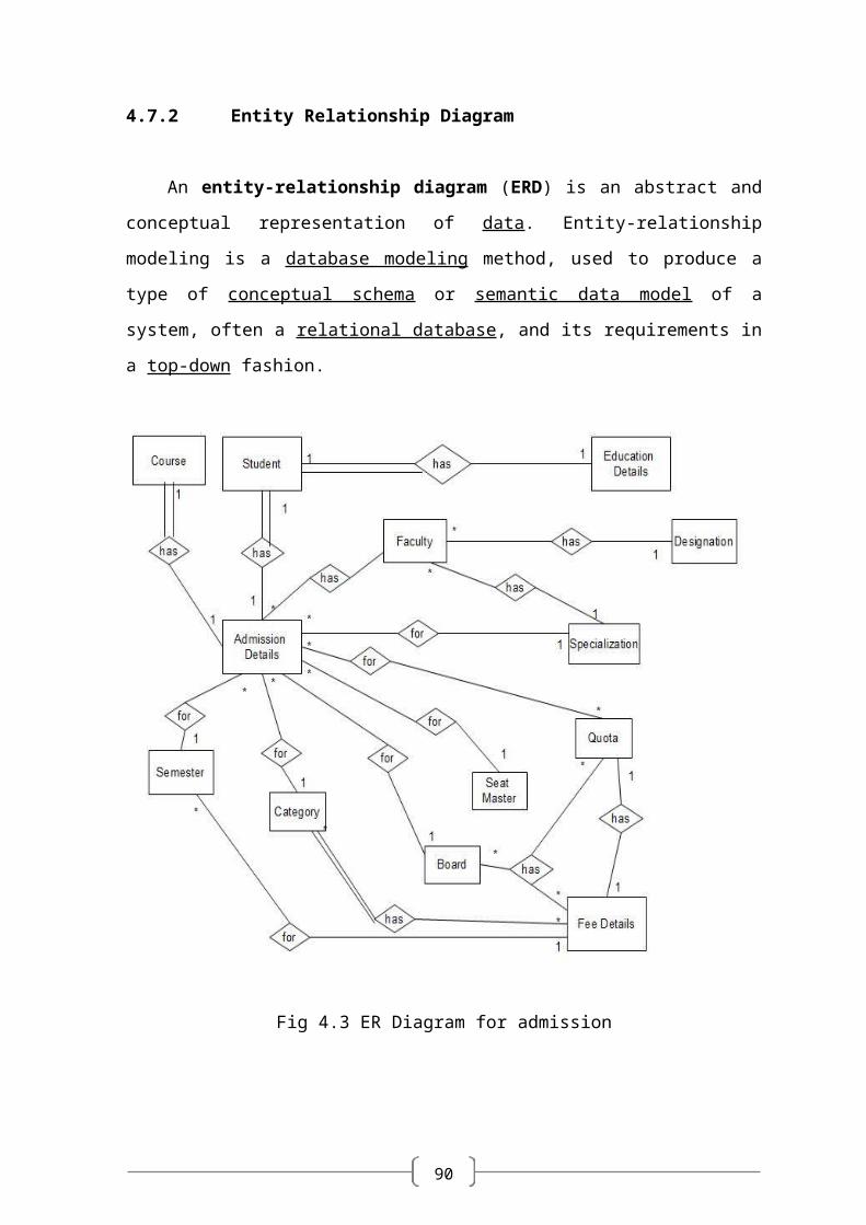
4.7.2 Entity Relationship Diagram
An entity-relationship diagram (ERD) is an abstract and conceptual representation
of data. Entity-relationship modeling is a database modeling method, used to produce a
type of conceptual schema or semantic data model of a system, often a relational database,
and its requirements in a top-down fashion.
Fig 4.3 ER Diagram for admission
90
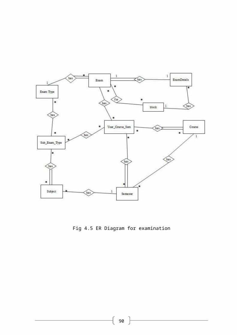
Fig 4.5 ER Diagram for examination
90
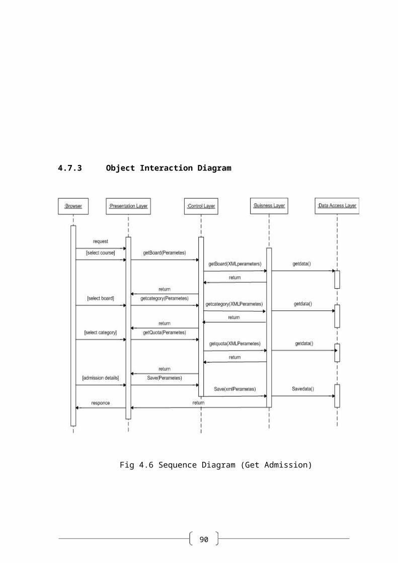
4.7.3 Object Interaction Diagram
Fig 4.6 Sequence Diagram (Get Admission)
90
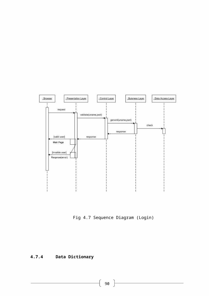
Fig 4.7 Sequence Diagram (Login)
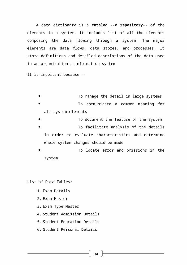
4.7.4 Data Dictionary
A data dictionary is a catalog --a repository-- of the elements in a system. It
includes list of all the elements composing the data flowing through a system. The major
elements are data flows, data stores, and processes. It store definitions and detailed
descriptions of the data used in an organization’s information system
It is important because –
To manage the detail in large systems
90
To communicate a common meaning for all system
elements
To document the feature of the system
To facilitate analysis of the details in order to evaluate
characteristics and determine where system changes should be made
To locate error and omissions in the system
List of Data Tables:
1. Exam Details
2. Exam Master
3. Exam Type Master
4. Student Admission Details
5. Student Education Details
6. Student Personal Details
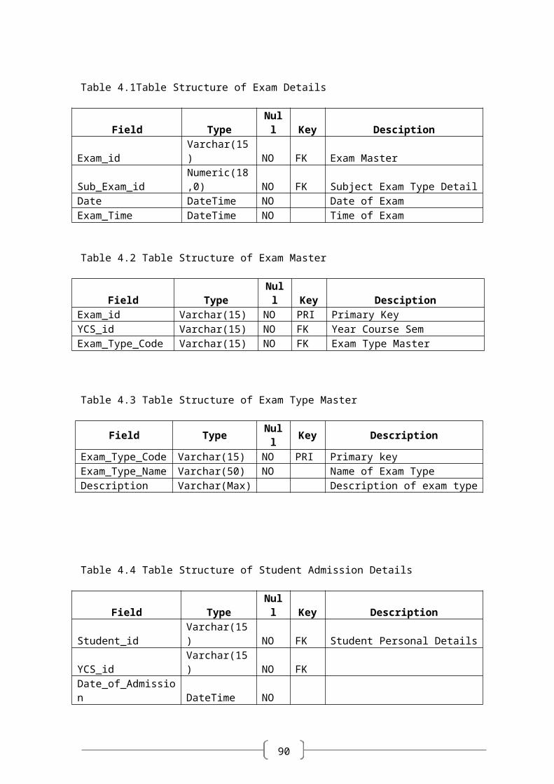
Table 4.1Table Structure of Exam Details
Field Type Null Key DesciptionExam_id Varchar(15) NO FK Exam MasterSub_Exam_id Numeric(18,0) NO FK Subject Exam Type DetailDate DateTime NO Date of ExamExam_Time DateTime NO Time of Exam
Table 4.2 Table Structure of Exam Master
Field Type Null Key DesciptionExam_id Varchar(15) NO PRI Primary KeyYCS_id Varchar(15) NO FK Year Course SemExam_Type_Code Varchar(15) NO FK Exam Type Master
Table 4.3 Table Structure of Exam Type Master
Field Type Null Key DescriptionExam_Type_Code Varchar(15) NO PRI Primary keyExam_Type_Name Varchar(50) NO Name of Exam TypeDescription Varchar(Max) Description of exam type
90
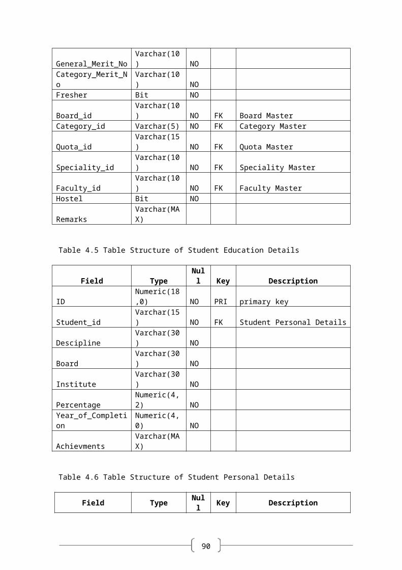
Table 4.4 Table Structure of Student Admission Details
Field Type Null Key DescriptionStudent_id Varchar(15) NO FK Student Personal DetailsYCS_id Varchar(15) NO FKDate_of_Admission DateTime NOGeneral_Merit_No Varchar(10) NOCategory_Merit_No Varchar(10) NOFresher Bit NOBoard_id Varchar(10) NO FK Board MasterCategory_id Varchar(5) NO FK Category MasterQuota_id Varchar(15) NO FK Quota MasterSpeciality_id Varchar(10) NO FK Speciality MasterFaculty_id Varchar(10) NO FK Faculty MasterHostel Bit NORemarks Varchar(MAX)
Table 4.5 Table Structure of Student Education Details
Field Type Null Key DescriptionID Numeric(18,0) NO PRI primary keyStudent_id Varchar(15) NO FK Student Personal DetailsDescipline Varchar(30) NOBoard Varchar(30) NOInstitute Varchar(30) NOPercentage Numeric(4,2) NOYear_of_Completion Numeric(4,0) NOAchievments Varchar(MAX)
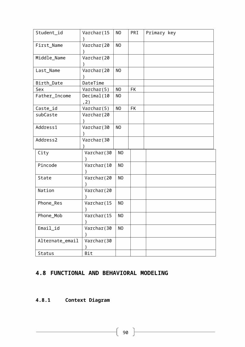
Table 4.6 Table Structure of Student Personal Details
Field Type Null Key DescriptionStudent_id Varchar(15) NO PRI Primary keyFirst_Name Varchar(20) NOMiddle_Name Varchar(20)Last_Name Varchar(20) NOBirth_Date DateTimeSex Varchar(5) NO FKFather_Income Decimal(10,2) NOCaste_id Varchar(5) NO FKsubCaste Varchar(20)Address1 Varchar(30) NOAddress2 Varchar(30)
City Varchar(30) NOPincode Varchar(10) NOState Varchar(20) NO
90
Nation Varchar(20)Phone_Res Varchar(15) NOPhone_Mob Varchar(15) NOEmail_id Varchar(30) NOAlternate_email Varchar(30)Status Bit
4.8 FUNCTIONAL AND BEHAVIORAL MODELING
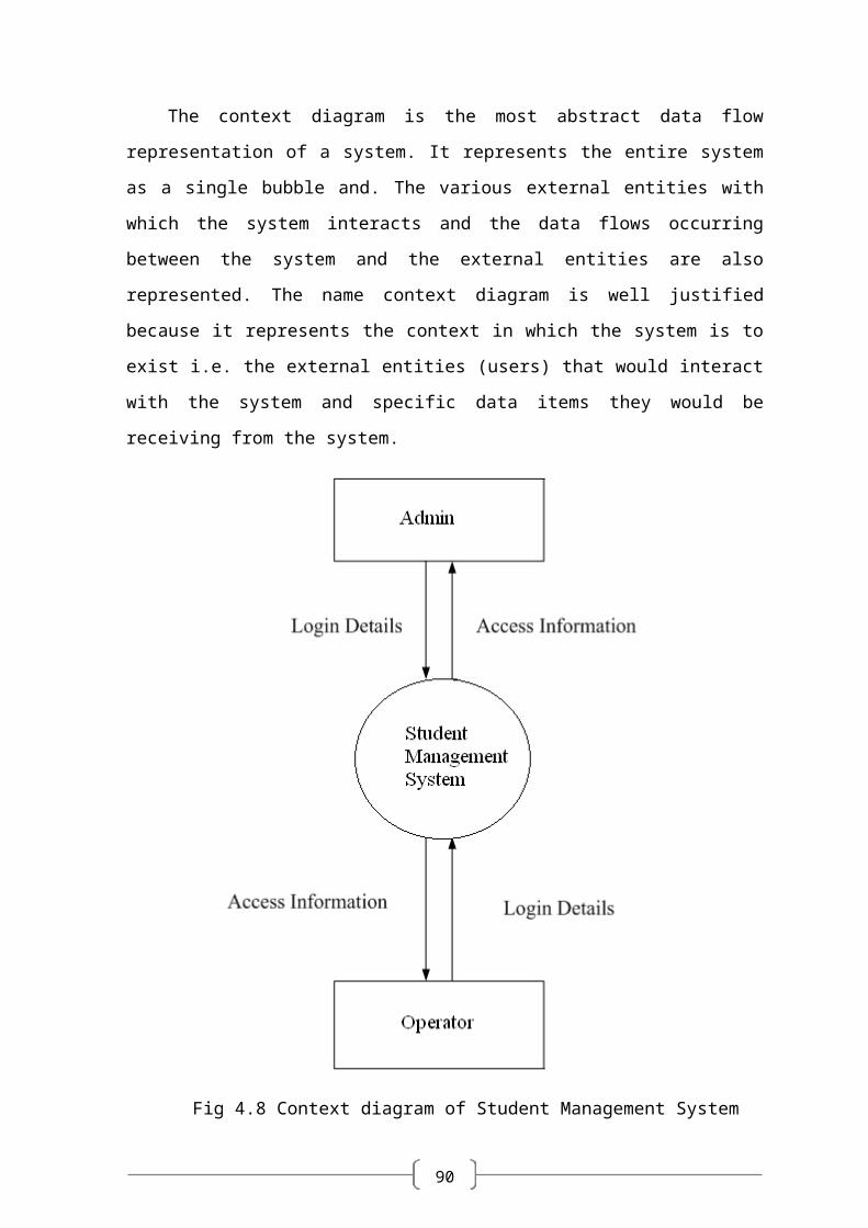
4.8.1 Context Diagram
The context diagram is the most abstract data flow representation of a system. It
represents the entire system as a single bubble and. The various external entities with
which the system interacts and the data flows occurring between the system and the
external entities are also represented. The name context diagram is well justified because it
represents the context in which the system is to exist i.e. the external entities (users) that
would interact with the system and specific data items they would be receiving from the
system.
90
Fig 4.8 Context diagram of Student Management System
90
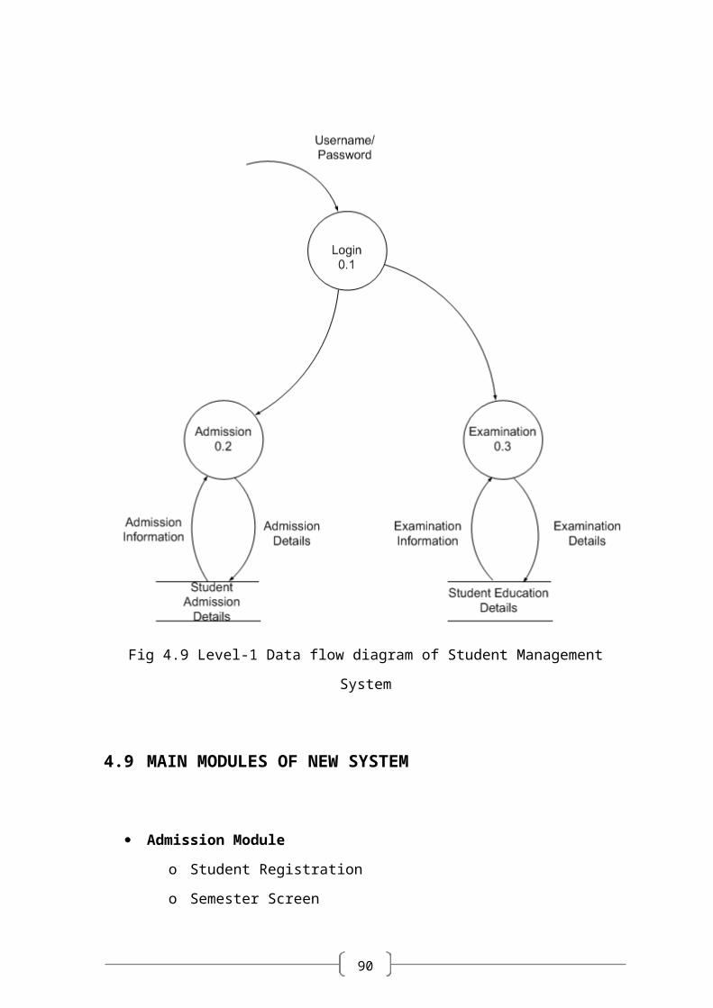
Fig 4.9 Level-1 Data flow diagram of Student Management System
4.9 MAIN MODULES OF NEW SYSTEM
Admission Module
o Student Registration
o Semester Screen
o Category Screen
o Payment Screen
o Faculty Screen
o Seat Master
90
o Student Fees Screen
o Roll No. Generation Screen
o Student Report Generation Screen
Examination Module
o Exam Type Screen
o Examination Scheduling Screen
o Subject Master Screen
o Subject Examination Marks Allocation Screen
o Subject Allocation Master
o Result Entry Screen
o Examination Scheduling Report
4.10 SELECTION OF HARDWARE AND SOFTWARE
JUSTIFICATION
The development of the system “STUDENT IDENTIFICATION SYSTEM” is
composed of the following components:
Java Script.
ASP.NET
XML (Extensible Markup Language).
SQL Server 2005.
PHOTSHOP
AJAX
AAA LOGO
1. JavaScript:
JavaScript is the programming language of the web.
Java Scripts can be inserted into HTML documents, to make the web pages
more dynamic and interactive
90
JavaScript is a scripting language.
JavaScript is supported by Major web browsers.
When a JavaScript is inserted into an HTML document, the Internet browser
will read the HTML and interpret the JavaScript.
JavaScript gives HTML designers a programming tool
JavaScript is a very light programming language with very simple syntax.
JavaScript can put dynamic text into an HTML page
2. ASP .NET:
ASP.NET is Microsoft's new Internet and Web strategy
ASP.NET is NOT a new operating system
ASP.NET is a new Internet and Web based infrastructure
ASP.NET delivers software as Web Services
ASP.NET is a framework for universal services
ASP.NET is a server centric computing model
ASP.NET will run in any browser on any platform
ASP.NET is based on the newest Web standards
3. .NET Framework 3.5
The .NET Framework is Microsoft's comprehensive and consistent programming
model for building applications that have visually stunning user experiences, seamless and
secure communication, and the ability to model a range of business processes.
The .NET Framework 3.5 introduces new features for the technologies in 2.0 and
3.0 and additional technologies in the form of new assemblies. The following technologies
are introduced with the .NET Framework 3.5:
Language Integrated Query (LINQ).
90
New compilers for C#, Visual Basic, and C++.
ASP.NET AJAX.
4. Hyper Text Mark-Up Language (HTML)
HTML = HyperText Mark-up Language
Universal, non-proprietary, structured, text mark-up language
Used to publish documents on the World Wide Web
Used to define the structure of documents and links between documents
An application of Standard Generalized Mark-up Language.
Style sheets
Scripting
Internationalization
Accessibility
5. Extensible Markup Language (XML)
XML stands for Extensible Markup Language
XML is a markup language much like HTML.
XML was designed to describe data.
XML tags are not predefined in XML. You must define your own tags.
XML uses a DTD (Document Type Definition) to describe the data.
XML with a DTD is designed to be self-describing.
90
Chapter 5
SYSTEM DESIGN ________________________________________________
90
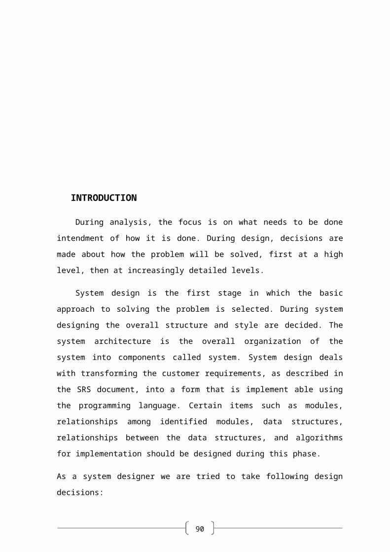
INTRODUCTION
During analysis, the focus is on what needs to be done intendment of how it is done.
During design, decisions are made about how the problem will be solved, first at a high
level, then at increasingly detailed levels.
System design is the first stage in which the basic approach to solving the problem is
selected. During system designing the overall structure and style are decided. The system
architecture is the overall organization of the system into components called system.
System design deals with transforming the customer requirements, as described in the SRS
document, into a form that is implement able using the programming language. Certain
items such as modules, relationships among identified modules, data structures,
relationships between the data structures, and algorithms for implementation should be
designed during this phase.
As a system designer we are tried to take following design decisions:
Organize the system into modules
Organize sub-modules for each module
Allocate tasks to processors
Choose an approach to manage data store
Handle access to global resources
Choose implementation logic
90
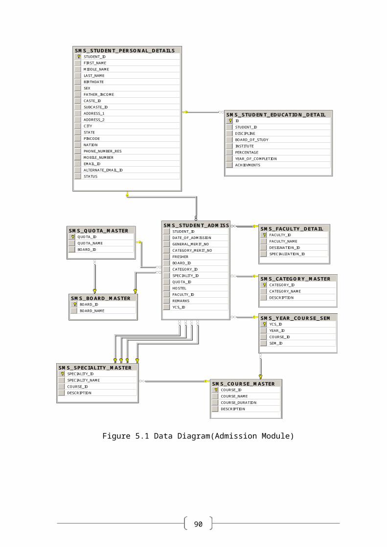
5.1DATABASE DESIGN
SMS_BOARD_MASTERBOARD_ID
BOARD_NAME
SMS_CATEGORY_MASTERCATEGORY_ID
CATEGORY_NAME
DESCRIPTION
SMS_COURSE_MASTERCOURSE_ID
COURSE_NAME
COURSE_DURATION
DESCRIPTION
SMS_FACULTY_DETAILFACULTY_ID
FACULTY_NAME
DESIGNATION_ID
SPECIALIZATION_ID
SMS_QUOTA_MASTERQUOTA_ID
QUOTA_NAME
BOARD_ID
SMS_SPECIALITY_MASTERSPECIALITY_ID
SPECIALITY_NAME
COURSE_ID
DESCRIPTION
SMS_STUDENT_ADMISSION_DETAILSSTUDENT_ID
DATE_OF_ADMISSION
GENERAL_MERIT_NO
CATEGORY_MERIT_NO
FRESHER
BOARD_ID
CATEGORY_ID
SPECIALITY_ID
QUOTA_ID
HOSTEL
FACULTY_ID
REMARKS
YCS_ID
SMS_STUDENT_EDUCATION_DETAILID
STUDENT_ID
DISCIPLINE
BOARD_OF_STUDY
INSTITUTE
PERCENTAGE
YEAR_OF_COMPLETION
ACHIEVMENTS
SMS_STUDENT_PERSONAL_DETAILSSTUDENT_ID
FIRST_NAME
MIDDLE_NAME
LAST_NAME
BIRTHDATE
SEX
FATHER_INCOME
CASTE_ID
SUBCASTE_ID
ADDRESS_1
ADDRESS_2
CITY
STATE
PINCODE
NATION
PHONE_NUMBER_RES
MOBILE_NUMBER
EMAIL_ID
ALTERNATE_EMAIL_ID
STATUS
SMS_YEAR_COURSE_SEMYCS_ID
YEAR_ID
COURSE_ID
SEM_ID
Figure 5.1 Data Diagram(Admission Module)
90
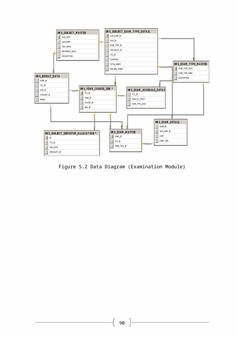
SMS_EXAM_DETAILEXAM_ID
SUB_EXAM_ID
DATE
EXAM_TIME
SMS_EXAM_MASTEREXAM_ID
YCS_ID
EXAM_TYPE_ID
SMS_EXAM_SCHEDULE_DETAILYCS_ID
YEAR_OF_STUDY
EXAM_TYPE_CODE
SMS_EXAM_TYPE_MASTEREXAM_TYPE_CODE
EXAM_TYPE_NAME
DESCRIPTIONSMS_RESULT_DATA
EXAM_ID
YCS_ID
SUB_ID
STUDENT_ID
MARKS
SMS_SUBJECT_EXAM_TYPE_DETAILSUB_EXAM_ID
SUB_ID
EXAM_TYPE_ID
SPECIALITY_ID
YCS_ID
DURATION
TOTAL_MARKS
PASSING_MARKS
SMS_SUBJECT_MASTERSUB_CODE
SUB_NAME
TEXT_BOOK
REFERENCE_BOOK
DESCRIPTION
SMS_YEAR_COURSE_SEM *YCS_ID
YEAR_ID
COURSE_ID
SEM_ID
SMS_SUBJECT_SEMESTER_ALLOCATION *ID
YCS_ID
SUB_CODE
SPECIALITY_ID
Figure 5.2 Data Diagram (Examination Module)
90
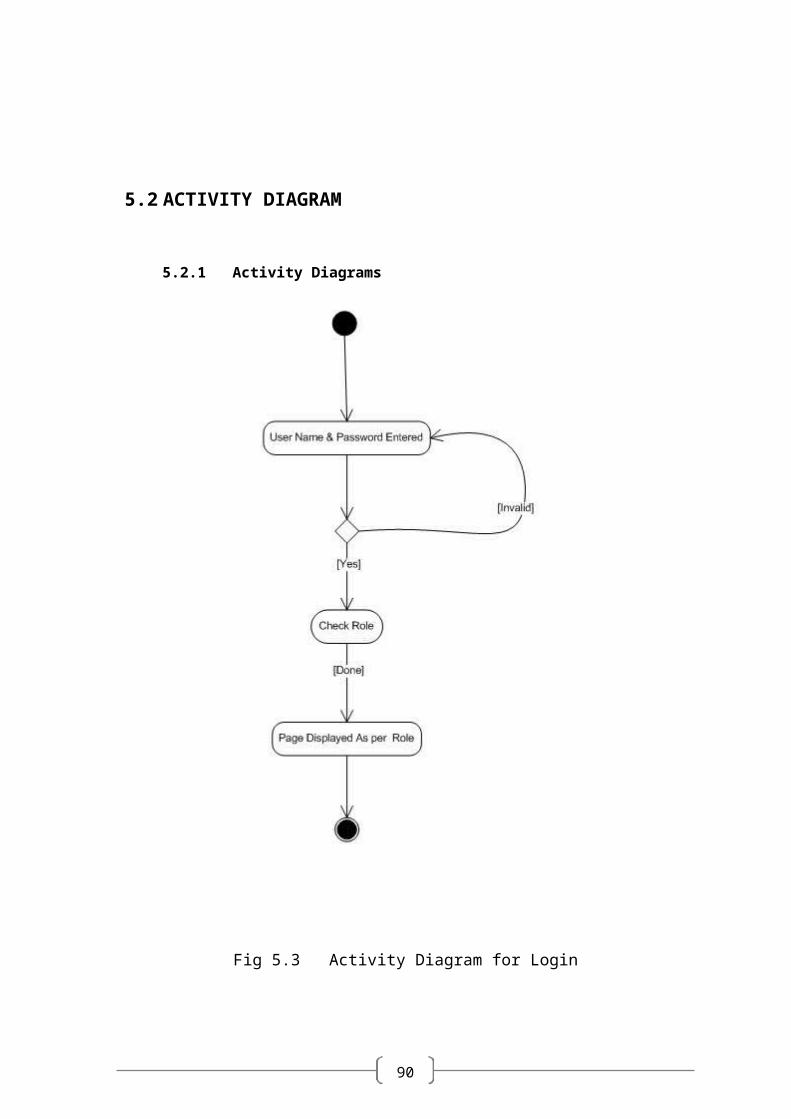
5.2 ACTIVITY DIAGRAM
5.2.1 Activity Diagrams
Fig 5.3 Activity Diagram for Login
90
Chapter 6
IMPLEMENTATION PLANNING ________________________________________________
90
6.1 IMPLEMENTATION ENVIRONMENT
The implementation view of software requirement presents the real world
manifestation of processing functions and information structures. This computerized
system is specified in a manner that dictates accommodation of certain implementation
details.
The implementation environment of the developed system facilitates multiple users
to use this system simultaneously. The user interfaces are designed keeping in mind that
the users of this system are familiar to using GUI-based systems. Thus, we restricted
ourselves to developing a GUI-based system so that it becomes easier for the end user to
get acquainted to the developed system.
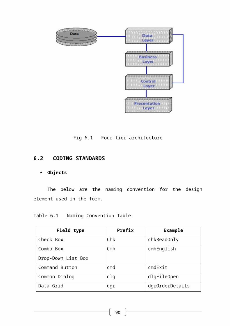
We have also followed the web based 4-tier architecture as the implementation
architecture which is as follows:
The presentation tier or user services layer:
This layer gives a user access to the application. It contains all the web pages so it
is this interface through which user can access the application.
This layer presents data to the user and optionally permits data manipulation and
data entry.
The control tier or control layer:
This layer gives a well separation between code and its connectivity with database.
This layer includes the code (VB.NET code) and JS. Mainly this layer includes the
replica of presentation layer pages and these pages are mainly control pages.
The business services layer:
It consists of business and data rules. Also referred to as the business logic tier, the
middle tier is where we as developers can solve mission-critical business problems
and achieve major productivity advantages. The components that make up this
layer can exist on a server machine, to assist in resource sharing. These
90
components can be used to enforce business rules, such as business algorithms and
data rules, which are designed to keep the data structures consistent within either
specific or multiple databases. Because these middle-tier components are not tied
to a specific client, they can be used by all applications and can be moved to
different locations, as response time and other rules require.
In our project we had created various classes appropriate to database and we
implemented business logic here. According to request from presentation layer the
appropriate rules called and it can access data through data tier.
The data tier or data services layer:
This layer interacts with persistent data usually stored in a database or in
permanent storage.
In this layer we have implemented the basic function through data can be
accessed like insert, update, delete, selection.
Our Requirements are changing dynamically so we used four-tier architecture. The
four-tier approach provides benefits such as reusability, flexibility, manageability,
maintainability, and scalability.
Fig 6.1 Four tier architecture
90
6.2 CODING STANDARDS
Objects
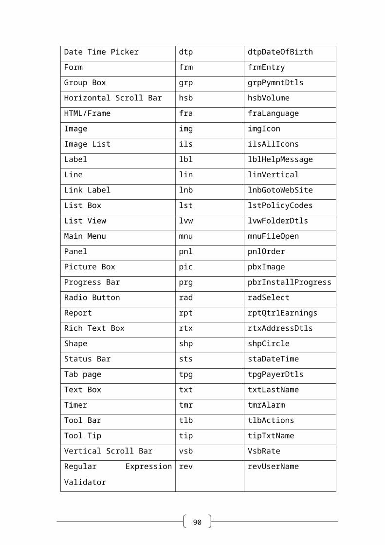
The below are the naming convention for the design element used in the form.
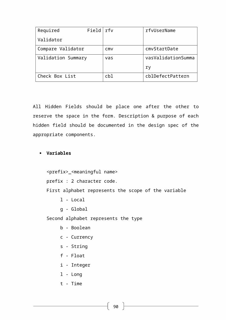
Table 6.1 Naming Convention Table
Field type Prefix Example
Check Box Chk chkReadOnly
Combo Box
Drop-Down List Box
Cmb cmbEnglish
Command Button cmd cmdExit
Common Dialog dlg dlgFileOpen
Data Grid dgr dgrOrderDetails
Date Time Picker dtp dtpDateOfBirth
Form frm frmEntry
Group Box grp grpPymntDtls
Horizontal Scroll Bar hsb hsbVolume
HTML/Frame fra fraLanguage
Image img imgIcon
Image List ils ilsAllIcons
Label lbl lblHelpMessage
Line lin linVertical
Link Label lnb lnbGotoWebSite
List Box lst lstPolicyCodes
List View lvw lvwFolderDtls
Main Menu mnu mnuFileOpen
Panel pnl pnlOrder
Picture Box pic pbxImage
Progress Bar prg pbrInstallProgress
Radio Button rad radSelect
Report rpt rptQtr1Earnings
90
Rich Text Box rtx rtxAddressDtls
Shape shp shpCircle
Status Bar sts staDateTime
Tab page tpg tpgPayerDtls
Text Box txt txtLastName
Timer tmr tmrAlarm
Tool Bar tlb tlbActions
Tool Tip tip tipTxtName
Vertical Scroll Bar vsb VsbRate
Regular Expression Validator rev revUserName
Required Field Validator rfv rfvUserName
Compare Validator cmv cmvStartDate
Validation Summary vas vasValidationSummary
Check Box List cbl cblDefectPattern
All Hidden Fields should be place one after the other to reserve the space in the form.
Description & purpose of each hidden field should be documented in the design spec of
the appropriate components.
Variables
<prefix>_<meaningful name>
prefix : 2 character code.
First alphabet represents the scope of the variable
l - Local
g - Global
Second alphabet represents the type
b - Boolean
c - Currency
s - String
f - Float
i - Integer
90
l - Long
t - Time
a - Array
v - Variant
The body of the variable names and function names should use mixed case and
should be as long as needed to describe their purpose. To keep the name length reasonable,
abbreviations can be used for standard terms like Init for initialization, Tbl for table, Cnt
for count, Grp for Group etc. Wherever abbreviations are used, try to use them
consistently to improve readability. And in meaningful variable name variable name start
with lower case salphabet and second part of the name should be start with upper case
alphabet like for student name variable name should be studentName.
Recommended Maximum Length for variable names is 32 characters.
Example:
For declaring a global string variable for Group name: gs_grpName.
When passing values to a subroutine/function, use the same variable names in the
called routine as in the calling routine.
For Functions and Subroutines
<prefix>_<meaningful name>
For Functions: prefix is fn
90
Chapter 7
TESTING ______________________________________________
90
7.1 TESTING PLAN
Software Testing has a dual function; it is used to identify the defects in program and it is
used to help judge whether or not program is usable in practice. Thus software testing is
used for validation and verification, which ensure that software conforms to its
specification and meets need of the software customer.
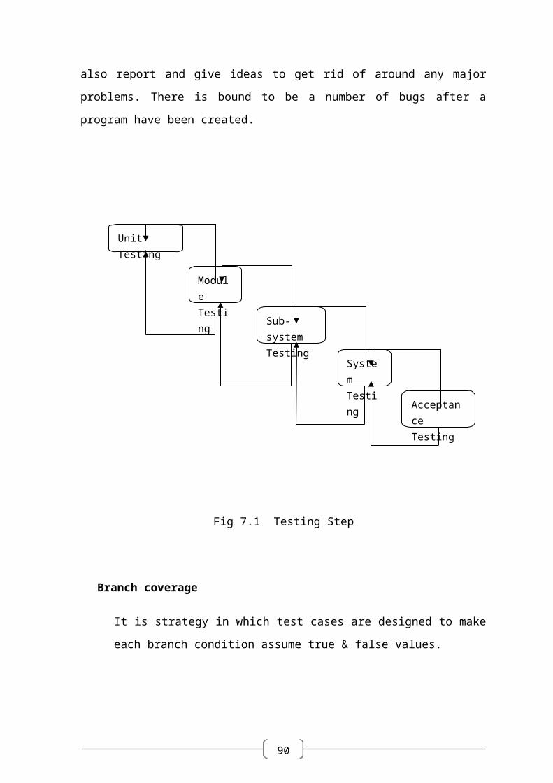
Developer resorted Alpha testing, which usually comes in after the basic design of the
program has been completed. The project scientist will look over the program and give
suggestions and ideas to improve or correct the design. They also report and give ideas to
get rid of around any major problems. There is bound to be a number of bugs after a
program have been created.
Fig 7.1 Testing Step
Unit Testing
Module Testing
Sub-system Testing
System Testing
Acceptance Testing
90
Branch coverage
It is strategy in which test cases are designed to make each branch condition
assume true & false values.
Conditional coverage
In this testing test cases are designed to make each component of composite
conditional expression both true & false.
The Testing Process
We test the software process activities such as Design, Implementation, and Requirement
Engineering. Because, design errors are very costly to repair once system has been started
to operate, it is quite obvious to repair them at early stage of the system. So analysis is the
most important process of any project.
Requirement Traceability
As most interested portion is whether the system is meeting its requirements or not, for
that testing should be planned so that all requirements are individually tested. We checked
the output of certain combination of inputs so that we can know whether it gives desirable
results or not. Strictly sticking to your requirements specifications, give you the path to get
desirable results from the system.
Testing Schedule
We have tested each procedure back-to-back so that errors and omissions can be found as
early as possible. Once the system has been developed fully we tested it on other
machines, which differs in configuration.
90
7.2 TESTING STRATEGY
There are types of testing that we implement. They are as follows:
While deciding on the focus of testing activities, study project priorities. For
example, for an on-line system, pay more attention to response time. Spend more
time on the features used frequently.
Decide on the effort required for testing based on the usage of the system. If the
system is to be used by a large number of users, evaluate the impact on users due
to a system failure before deciding on the effort.
A necessary part of the test case is a definition of the expected result.
Write test cases for invalid and unexpected as well as valid and expected input
conditions.
Thoroughly inspect the results of each test.
We have performed both Unit Testing and System Testing on WIMS to detect and
fix errors. A brief description of both is given below.
Unit Testing
Objective
The objective of Unit Testing is to test a unit of code (program or set of programs) using
the Unit Test Specifications, after coding is completed. Since the testing will depend on
the completeness and correctness of test specifications, it is important to subject these to
quality and verification reviews.
Input
Unit Test Specifications
90
Code to be tested
Testing Process
Checking for availability of Code Walk-through reports which have documented
the existence of and conformance to coding standards.
Verify the Unit Test Specifications conform to the program specifications.
Verify that all boundary and null data conditions are included.
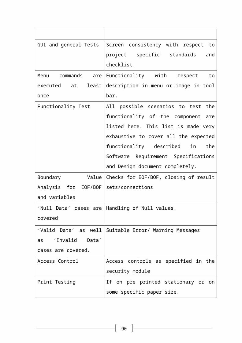
Features to be tested
Table 7.1 Feature tested table
Test Specification Description
GUI and general Tests Screen consistency with respect to project specific
standards and checklist.
Menu commands are executed at
least once
Functionality with respect to description in menu or
image in tool bar.
Functionality Test All possible scenarios to test the functionality of the
component are listed here. This list is made very
exhaustive to cover all the expected functionality
described in the Software Requirement Specifications
and Design document completely.
Boundary Value Analysis for
EOF/BOF and variables
Checks for EOF/BOF, closing of result
sets/connections
‘Null Data’ cases are covered Handling of Null values.
‘Valid Data’ as well as ‘Invalid
Data’ cases are covered.
Suitable Error/ Warning Messages
Access Control Access controls as specified in the security module
Print Testing If on pre printed stationary or on some specific paper
size.
90
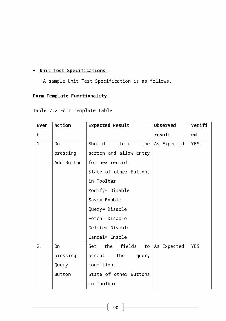
Unit Test Specifications
A sample Unit Test Specification is as follows.
Form Template Functionality
Table 7.2 Form template table
Event Action Expected Result Observed result Verified
1. On pressing
Add Button
Should clear the screen and allow
entry for new record.
State of other Buttons in Toolbar
Modify= Disable
Save= Enable
Query= Disable
Fetch= Disable
Delete= Disable
Cancel= Enable
As Expected YES
2. On pressing
Query Button
Set the fields to accept the query
condition.
State of other Buttons in Toolbar
Modify= Disable
Save= Disable
Add = Disable
Fetch= Enable
Delete= Disable
Cancel= Enable
As Expected YES
3. On pressing
Fetch button
Get all the records, which satisfy
the query condition.
State of other Buttons in Toolbar
As Expected YES
90
Modify= Enable
Save= Disable
Query= Enable
Add= Enable
Delete= Enable
Cancel= Disable
4. On pressing
Save button
Record should be inserted in
database
State of other Buttons in Toolbar
Modify= Enable
Add= Enable
Query= Enable
Fetch= Disable
Delete= Enable
Cancel= Disable
As Expected YES
5. On pressing
Modify button
Record should be updated.
State of other Buttons in Toolbar
Add= Disable
Save= Enable
Query= Disable
Fetch= Disable
Delete= Disable
Cancel= Enable
As Expected YES
6. On pressing
Cancel button
Screen should go into default
mode of screen
State of other Buttons in Toolbar
Modify= Disable
Save= Disable
Query= Enable
Fetch= Disable
Delete= Disable
Add= Enable
As Expected YES
7. Delete button. Not Applicable As Expected YES
90
8. Form load event The form should open in Cancel
Mode
As Expected YES
9. Status bar status User ID, Screen ID and Screen
Mode is set. Also on the focus
event of any input control the
tool tip is displayed in the status
bar
As Expected YES
10. Security
Features
According to the Access rights
defined the corresponding
buttons should be Enabled
/Disabled
As Expected YES
Integration Testing
After our individual modules were tested out we proceed to the integration testing to
create a complete system. This integration process involves building the system and
testing the resultant system for problems that arise from component interactions.
We have applied top-down strategy to validate high-level components of a system before
design and implementations have been completed. Our development process started with
high-level components and we worked down the component hierarchy.
System Testing
System testing is actually a series of tests whose purpose is to fully exercise the computer-
based system. It verifies that system elements have been properly integrated and perform
allocated functions. It checks whether the system as a whole works as per requirement. We
have used Performance testing. Performance testing - designed to test the run-time
performance of software, especially real-time software.
Performance Testing
This is designed to test the run-time performance of software within the context of an
integrated system. Performance testing occurs throughout all steps in the testing process.
Our system is checked for high load as well as low load.
90
Statistical Testing
Statistical Testing is used to test the program’s performance and reliability and to check
how it works under operational conditions. Tests are designed to reflect the actual user
inputs and their frequency.
The stages involved in the static analysis for this system are follows.
Control flow analysis
Unreachable code
Unconditional branches into loops
Data use analysis
Variable used before initialization
Variables declared but never used
Variables assigned twice but never used between assignments
Possible array bound violations
Declared variables
Interface analysis
Parameter type mismatches
Parameter number mismatches
Non-usage of the results of functions
Uncalled functions and procedures
Storage management faults
Images not Stored in Resources
Out of Bound ->Program’s non-volatile memory.
90
7.3 TEST CASES
A test case is a set of conditions or variables and inputs that are developed for a particular
goal or objective to be achieved on a certain application to judge its capabilities or
features.
It might take more than one test case to determine the true functionality of the application
being tested. Every requirement or objective to be achieved needs at least one test case.
Some software development methodologies like Rational Unified Process (RUP)
recommend creating at least two test cases for each requirement or objective; one for
performing testing through positive perspective and the other through negative
perspective.
90
Chapter 8
SCREEN SHOTS AND USER MANUAL ______________________________________________
90
ADMISSION MODULE
Fig 8.1 Screen shot showing new admission add mode
At the time of admission students information like personal details, contact details,
admission details and education details are saved in the database and the student id is
generated by the system.
90
Fig 8.2 Screen shot showing new admission in query mode
In fetch mode as you can see when you click on the student id LoV it will display
the list of students’ information (student id and name) according to the type of attribute
you select whether it is student id or it may be student name. Now from the list of the
students in the LoV you can select any one student and on that basis you can fetch his/her
information.
90
Fig 8.3 Screen shot showing new admission in fetch mode
In fetch mode according to student id you select from the LoV (list of values), when
you click on the fetch all the information of the student will be displayed on the screen as
shown in the figure.
90
Fig 8.4 Screen shot showing validation in new admission in save mode
In Add Mode if mandatory fields are not mentioned and the user try to save, then
system will prompt to fill the mandatory fields.
90
Fig 8.5 Screen shot showing new admission in Saved mode
In Saved mode, after clicking the Save button from the Button Bar, system will pop
up a message box showing the current Student ID generated.
90
EXAMINATION MODULE
Fig 8.6 Screen shot showing Menu
In this screen, the menu is shown which contains the entire screen module wise and
this menu is auto hidden when a screen name is clicked from the menu.
90
Fig 8.7 Screen shot showing Subject Master Screen in Add mode
In add mode, the subject code and subject name are mandatory and text book and
reference book name, description are optional.

90
Chapter 9
LIMITATIONS AND ENHANCEMENTS ______________________________________________
90
9.1 LIMITATIONS
The part of the system can be implemented using the current technology although
some modifications had to be done at various places. At various places some alterations
with the prototypes and functionalities would be done in order to work out the cost
constraints and to cope with the scheduling constraints.
In this system we have don’t have facility for attendance management of
student.
In this application search is limited to String or by number. Cannot do search by
photo and figure prints.
9.2 FUTURE ENHANCEMENT
The SMS has been developed with a main aim of making work easier and
timesaving for the human capital. The whole system is bi-lingual at present and can be
extended to other languages too with minor changes (not in coded).
The coding pattern is kept as dynamic as possible with minimum amount of static
values to make it easier for future extensions. As the current system is expected to add
more functionality and dependency according to requirement changes and technology,
proper coding standards and working platform have been kept in mind to produce a quality
product.
One enhancement is that we can make this application in more than 1 language as
well. Adding attendance management is also one option for enhancement.
90
Chapter 10
CONCLUSION AND DISCUSSION ______________________________________________
90
10.1 CONCLUSION
SIS will be helpful to perform paperless work and manage all data.
This provides easy, accurate, unambiguous and faster data access.
Lesser learning curve - Consistent user interface, customized for the group of
users, statistical information in various graphical and tabular forms.
10.2 DISCUSSION
10.2.1 Self Analysis of Project Viabilities
SIS is a very efficient system for the management of student admission and
examination. Most of all the task of admission and examination can be easily done
with this system. This can be used by any organization.
Also this system uses the latest technologies like AJAX, XML. So it was easy
enough to develop the project. If any changes in the system are to be made then they
can be done very easily.
10.2.2 Problem Encountered and Possible Solutions
Problem of creating control using JavaScript were faced during development. But
with help of internal guide and other team members problems were solved.
The problems encountered during the training undergone at Tata Consultancy
Services were purely due to lack of knowledge in various technical aspects. The
lack of in depth knowledge in various concepts of java script, database concepts,
etc. was the problems faced.
Moreover the lack of practical know-how of these aspects did cause a few
hindrances in early stages of training but later with the help and guidance of team
members it became easier to cope up with these concepts and applications.
90
REFERENCES
Web Sites
www.msdn.microsoft.com
-Microsoft official website
http://sourceforge.net/
- Largest repository of open source code and applications available on the
internet
http://www.gnu.org
- Web site of the Free Software Foundation (FSF) which supports the open
source community
http://www.thefreecountry.com
- Large collection of good programming resources
http://www.1001tutorials.com/
- Large collection of good tutorials for reference
http://www.codeguru.com/
- Good articles on programming.
90
Books
Asp.net Professional 1.1 (Wrox Publication)
By: Wrox Publication
JavaScript In 21 Days
JavaScript Bible
By: Danny Goodman
Mastering SQL Server 2000
Software Engineering – A Practitioner’s Approach
By: Roger S. Pressman
Software Engineering
By: Ian Somerville
VB.net Professional (Wrox Publication)
By: Wrox Publication
90
TIT College, Bhopal
Department of CSEMajor Project Weekly Progress Report
Name of the project: Student Identification System
Name of the group members: Aradhana Dubey (0199CS101027),Nirupama Waretwar (0199CS101060)
Name of the project Guide: Prof. Hari Singh Jatav
Week 1(17th Feb - 23th Feb’14)Remark : ……
………..
Sign
Week 2(24th Feb - 2th Mar’14)Remark : ……
………..
Sign
Week 3(3th Mar - 9th Mar’14)Remark : ……
……….. S
ign
Week 4(17th Mar - 23th Mar’14)Remark : ……
………..
Sign
90
Week 5(1th Apr - 6th Apr’14)Remark : ……
………..
Sign
Week 6(14th Apr - 20th Apr’14)Remark : ……
………..
Sign
Week 7(28th Apr - 4th May’14)Remark : ……
………..
Sign