studies on fuel cell vehicles & their scopes in india
TRANSCRIPT

STUDIES ON FUEL CELL VEHICLES AND THEIR SCOPE IN
INDIA
A Thesis
Submitted in partial fulfilment
of the requirement for the award of the degree
of
MASTER OF TECHNOLOGY
in
AUTOMOBILE ENGINEERING
by
HARSH GUPTA
(Enrolment No.: A7626214006)
Department of Mechanical & Automation Engineering
Amity School of Engineering and Technology
Amity University Uttar Pradesh,
Lucknow Campus
May, 2016

I dedicate this thesis to my mother Sangeeta Gupta, father Virender Gupta and
Sister's Jyoti Garg and Kanchan Bansal, because of whom, I am what I am
today. They motivated and encouraged me at every step. I owe immense
gratitude to shivika and my all friends who always stood by me at all times
during my master's degree, motivating me.
Page | i
DECLARATION
I hereby declare that this Thesis entitled "STUDIES ON FUEL CELL VEHICLES &
THEIR SCOPE IN INDIA" submitted in partial fulfilment of the requirement for the award
of the degree of Master of Technology in Automobile Engineering is my original work and
has not formed the basis for the award of any degree, associate ship, fellowship or any other
similar titles.
The work was done under the guidance of Professor (Dr.) A.K. Jouhari, at Amity School of
Engineering & Technology, Amity University.
Place: Lucknow Harsh Gupta
Date: (A7626214006)

Page | ii
CERTIFICATE
This is to certify that the thesis entitled "Studies on Fuel cell Vehicles & their Scope in
India" is a bonafide work carried out by HARSH GUPTA, Enrolment No. A7626214006,
is submitted, in partial fulfilment of the requirements for the award of the Degree of Master
of Technology in Automobile Engineering, to Amity University Uttar Pradesh and that
the thesis has not formed the basis for the award of any degree, diploma, associateship,
fellowship or any other similar title.
Place: Lucknow
Date:
Prof. (Dr.) A.K. Jouhari Wg. Cdr. (Dr.) Anil Kumar
(Thesis Guide) Director, ASET
Professor & Head Amity University Uttar Pradesh,
Department of Mechanical and Lucknow Campus
Automation Engineering

Page | iii
ACKNOWLEDGEMENT
This thesis becomes a reality with the kind support and helps of many individuals and would
like to extend my sincere thanks to all of them.
Foremost, I want to offer this endeavour to our GOD ALMIGHTY for the wisdom he
bestowed upon me, the strength, peace of my mind and good health in order to finish this
research.
I would like to express the deepest appreciation to my Guide Professor (Dr.) A.K. Jouhari,
who has the attitude and the substance of a genius he continually and convincingly conveyed
a spirit of adventure in regard to teaching without his guidance and persistent help this
dissertation would not have been possible.
I am highly indebted to Mr. Vivek Verma for his esteemed guidance and constant supervision
as well as for providing necessary information regarding the thesis.
I am also thankful to distinguished faculty members and staff of the Department of
Mechanical & Automation Engineering, Amity University, and Uttar Pradesh.
Page | iv
ABSTRACT
Today, the world is confronted with the crises of petroleum products like petrol and diesel,
which are mainly used as fuel in the present day automobiles. Also, the products of
combustion of conventional fuels result in environmental problems. So, one of the major aim
of the automobile industry is to improve vehicle fuel efficiency and performance with much
lesser harmful emissions. In this regard fuel cell vehicle (FCV), has various advantages such
as simplicity, low pollution, quietness and reliability. The Energy conversion efficiency of
fuel cell is 2-3 times higher than IC Engines. Hydrogen, being a clean fuel may find intensive
use as fuel in the days to come. Hydrogen can be used directly in the engine and the products
of combustion will be water in either liquid or in gaseous form. In this way the oxides of
carbon are totally avoided in the environment. Hydrogen can also be used in a fuel cell to
generate electrical energy, which in turn can be used in automobile. In this way, probably fuel
cells are considered to be the most promising and futuristic source of energy. A brief
description of fuel cell operating principle and its advantages are discussed and how it can be
implemented in the automobiles. Here in this thesis a design of fuel cell three wheeler auto is
also proposed.
Page | v
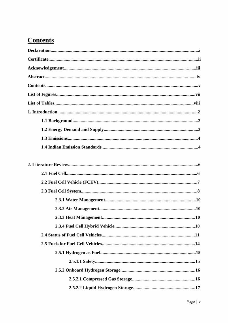
Contents
Declaration.................................................................................................................................i
Certificate.......................................................................................................................... ........ii
Acknowledgement...................................................................................................................iii
Abstract....................................................................................................................................iv
Contents..................................................................................................................... ................v
List of Figures.................................................................................................. .......................vii
List of Tables............................................................................................................... ..........viii
1. Introduction..................................................................................................................... .....2
1.1 Background.............................................................................................................2
1.2 Energy Demand and Supply..................................................................................3
1.3 Emissions.................................................................................................................4
1.4 Indian Emission Standards....................................................................................4
2. Literature Review.................................................................................................................6
2.1 Fuel Cell..................................................................................................................6
2.2 Fuel Cell Vehicle (FCEV)......................................................................................7
2.3 Fuel Cell System.....................................................................................................8
2.3.1 Water Management...............................................................................10
2.3.2 Air Management....................................................................................10
2.3.3 Heat Management.................................................................................10
2.3.4 Fuel Cell Hybrid Vehicle......................................................................10
2.4 Status of Fuel Cell Vehicles.................................................................................11
2.5 Fuels for Fuel Cell Vehicles.................................................................................14
2.5.1 Hydrogen as Fuel...................................................................................15
2.5.1.1 Safety.......................................................................................15
2.5.2 Onboard Hydrogen Storage.................................................................16
2.5.2.1 Compressed Gas Storage.......................................................16
2.5.2.2 Liquid Hydrogen Storage......................................................17
Page | vi
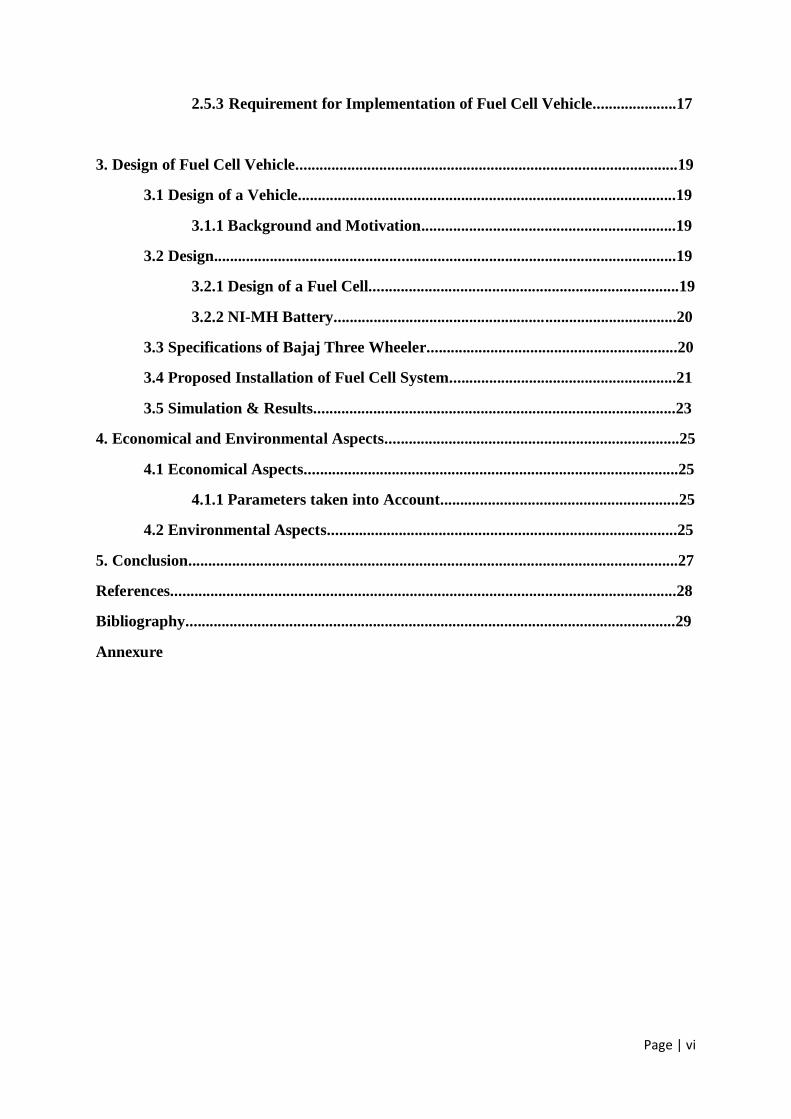
2.5.3 Requirement for Implementation of Fuel Cell Vehicle.....................17
3. Design of Fuel Cell Vehicle................................................................................................19
3.1 Design of a Vehicle...............................................................................................19
3.1.1 Background and Motivation................................................................19
3.2 Design....................................................................................................................19
3.2.1 Design of a Fuel Cell..............................................................................19
3.2.2 NI-MH Battery......................................................................................20
3.3 Specifications of Bajaj Three Wheeler...............................................................20
3.4 Proposed Installation of Fuel Cell System.........................................................21
3.5 Simulation & Results...........................................................................................23
4. Economical and Environmental Aspects..........................................................................25
4.1 Economical Aspects..............................................................................................25
4.1.1 Parameters taken into Account............................................................25
4.2 Environmental Aspects........................................................................................25
5. Conclusion...........................................................................................................................27
References...............................................................................................................................28
Bibliography...........................................................................................................................29
Annexure
Page | vii
List of Figures
FIGURE 1. ESTIMATE OF CONVENTIONAL OIL CONSUMPTION AND DISCOVERY ...................... 03
FIGURE 2. ENERGY SUPPLY FORECAST ................................................................................. 03
FIGURE 3. SCHEMATIC PRESENTATION OF PEM FUEL CELL ................................................... 07
FIGURE 4. THE EFFICIENCY OF DIFFERENT TECHNOLOGIES AS FUNCTION OF LOAD ................. 08
FIGURE 5. DIAGRAMMATIC REPRESENTATION OF SIMPLE FUEL CELL POWERTRAIN ................ 09
FIGURE 6. FUEL CELL WITH ITS AUXILIARY COMPONENTS .................................................... 09
FIGURE 7. EXAMPLE OF FUEL CELL VEHICLE ........................................................................ 14
FIGURE 8. EXPLOSION LIMITS OF STOICHIOMETRIC HYDROGEN OXYGEN MIXTURE ............... 15
FIGURE 9. DIFFERENT METHODS FOR ONBOARD HYDROGEN STORAGE .................................. 16
FIGURE 10. PREHEATING REQUIREMENTS FOR THE FUEL SUPPLIED FROM LIQUID HYDROGEN
TANK IN K .................................................................................................................... 17
FIGURE 11. REQUIREMENTS FOR SUCCESSFUL IMPLEMENTATION OF FUEL CELL VEHICLES..... 17
FIGURE 12. PEM EFFICIENCY VS. CURRENT DENSITY ........................................................... 19
FIGURE 13. BAJAJ RE 4S THREE WHEELER AUTO ................................................................. 21
FIGURE 14. PROPOSED PLACEMENT OF DIFFERENT COMPONENTS OF FUEL CELL SYSTEM ....... 21
FIGURE 15. POWER TRAIN DIAGRAM OF THE SYSTEM IN PSAT ............................................. 22
FIGURE 16. THE THREE WHEELER SPEED DEMAND FROM HWFET .......................................... 23
FIGURE 17. THE THREE WHEELER POWER DEMAND UNDER HWFET ........................................ 23
FIGURE 18. THE FUEL CELL OUTPUT POWER .......................................................................... 23

Page | viii
LIST OF TABLES
TABLE 1. MAIN EMISSIONS, CAUSES AND THEIR EFFECT ON HUMAN HEALTH .......................... 04
TABLE 2. INDIAN EMISSION STANDARDS (4-WHEEL VEHICLE) .............................................. 04
TABLE 3. LIST OF MODEL PRODUCED ................................................................................... 14
TABLE 4. SHOWS THE PROPERTIES OF HYDROGEN, METHANOL, GASOLINE AND DIESEL ......... 15
TABLE 5. SHOWS THE TECHNICAL SPECIFICATION OF THE BAJA RE 4S THREE WHEELER AUTO
.................................................................................................................................... 20

Page | 1
≈
Chapter One
≈
Page | 2
1. Introduction
Global air pollution is a serious problem and a challenge that humanity has to take seriously.
A major contributor to the air pollution is the automotive sector due to the heavy and
increasing traffic and use of fossil fuels, in spite of ongoing activities to promote efficiency,
the automobile sector is generating a significant increase in emissions. As transport levels are
expected to rise, especially in developing countries the dwindling supply of fossil fuels will
sooner or later become a limiting factor. Therefore, automobile manufacturers are looking for
a more promising and non-polluting source of energy which provides sufficient power while
being safe for the environment. At the same time a great deal of research and development on
fuel cell has taken place in finding an appropriate source of energy.
1.1 Background
The automobile is a vehicle that carries its own motor. These are designed to run primarily on
roads, to have seating for one to six persons, typically have four wheels and are constructed
principally for the transport of people and goods.
Nicolas-Joseph Cugnot is credited for creating a world first steam powered tricycle in 1769
whereas Karl Benz is acknowledged as the inventor of modern car in 1879. On the other
hand, first mass production car was a Ford Model T which was introduced in the year of
1908.
Now, we come to modern vehicle which are Electric Vehicle and are currently in trend. An
electric vehicle is an electric drive vehicle which uses one or more electric motors or traction
motors for propulsion. An electric vehicle may be powered through a battery or generator to
convert fuel chemical energy into electrical energy. They are also around three times as
efficient as cars with an internal combustion engine.
The first electric car was produced in the year 1880 but initially electric vehicles were not
entertained by the people. After 2008, a renaissance in electric vehicle has occurred as the
need to reduce greenhouse gas emissions were realised by people and the authorities due to
the severe effects of Global warming. But later a need of another source of power is realised
by automotive sector because of the emissions released in the air by the electricity generation
therefore fuel cell technology is introduced which proves to be a promising and long lasting
solution for the global warming occurred due to vehicular emissions.
As of 2010, study of CPCB (Central Pollution Control Board, India) shows that motor
vehicle use 50% of the fuel used in India and produce over 70% of CO emissions in Indian
metropolitan cities [1], therefore, a new source of energy is very essential to fulfil the future
energy demand and helps in CO emission reductions.

Page | 3
1.2 Energy demand and Supply
Figure 2 gives fuel oil consumption and discovery.
Figure 1. Estimate of Conventional Oil Consumption and Discovery
The above figure depicts that demand of conventional fuel has which already exceeded that
of discovery. Today most vehicles rely on fossil fuels whereas a new source of energy is
needed to meet the future energy need and for sustainable vehicle mobility.
Figure 3 shows the future energy supply forecast with all the sources together.
Figure 2. Energy Supply Forecast

Page | 4
1.3 Emissions
Table 1, shows the main emissions, their impact and effects caused by vehicles. Due to these
pollutants. The human health and environmental issues have forced many countries to create
some regulations. Emission damage both human health and the environment. Australia,
Sweden, Japan, California, USA were the first to implement the regulations. Nowadays, all
countries have started following these regulations or had made their own regulations.
Types of Pollutants Cause Symptoms
C (Carbon) Partially burnt fuel Smoke and odour
(Carcinogenic in nature)
CO (Carbon Monoxide) Incomplete combustion Drastic poisoning to the point
of death.
Cardiovascular diseases
HC (Hydrocarbon) Unburnt fuel Irritates eyes and nose
NOx (Oxide of Nitrogen) Very high flame temperature Toxic for Human
Pb (Lead) Petrol additives to raise
octane rating
Toxic to Human
Causes Physical and Mental
Disorder
Table 1. Main emissions, Causes and their effect on human health
1.4. Indian Emission Standards
Indian emission standards are named as Bharat stage Emission Standards instituted by
Government of India to regulate output emissions from motor vehicles. These Standards and
their Time of implementation is decided by Central Pollution Control Board (CPCB) in
collaboration with Ministry of Environment and Climate Change. [2]
Standard Reference YEAR Region
India 2000 Euro 1 2000 Nationwide
Bharat Stage II Euro 2
2001 NCR*, Mumbai,
Kolkata, Chennai
2003.04 NCR*, 13 Cities†
2005.04 Nationwide
Bharat Stage III Euro 3 2005.04 NCR*, 13 Cities†
2010.04 Nationwide
Bharat Stage IV Euro 4 2010.04 NCR*, 13 Cities†
Bharat Stage V Euro 5 (to be skipped)
Bharat Stage VI Euro 6 2020.04 (proposed) Entire country
India 2000 Euro 1 2000 Nationwide
* National Capital Region (Delhi)
† Mumbai, Kolkata, Chennai, Bengaluru, Hyderabad, Ahmedabad, Pune, Surat, Kanpur,
Lucknow, Sholapur, Jamshedpur and Agra.
Table 2 Indian Emission Standards (4-Wheel Vehicle)

Page | 5
≈
Chapter Two
≈
Page | 6
2. Literature Review
2.1 Fuel Cell
A fuel cell is a static energy conversion device that converts chemical energy of fuels directly
into electrical energy with some heat and water as its by-product [3].
There are basically five types of fuel cells:-
1. Proton Exchange Membrane Fuel Cell (PEMFC)
2. Phosphoric Acid Fuel Cell
3. Solid Oxide Fuel Cell
4. Hydrogen Oxygen Fuel Cell
5. Molten Carbonate Fuel Cell
Out of all the above, only Proton exchange membrane fuel cells are the most suitable for the
automobile applications as they operate at lower temperature/pressure ranges.
A PEM fuel cell consists of two porous carbon electrodes, the anode and the cathode,
separated by a polymer electrolyte, the ion-conducting proton exchange membrane (PEM).
Integrated between each electrode and the membrane is a thin layer of a catalyst. The
electrodes, catalyst and membrane together form the membrane electrode assembly (MEA)
and bipolar flow field plates, with gas channels grated into their surface, are placed on each
side of the MEA. The electrodes are connected to an external load circuit, e.g. an electric
motor in a vehicle.
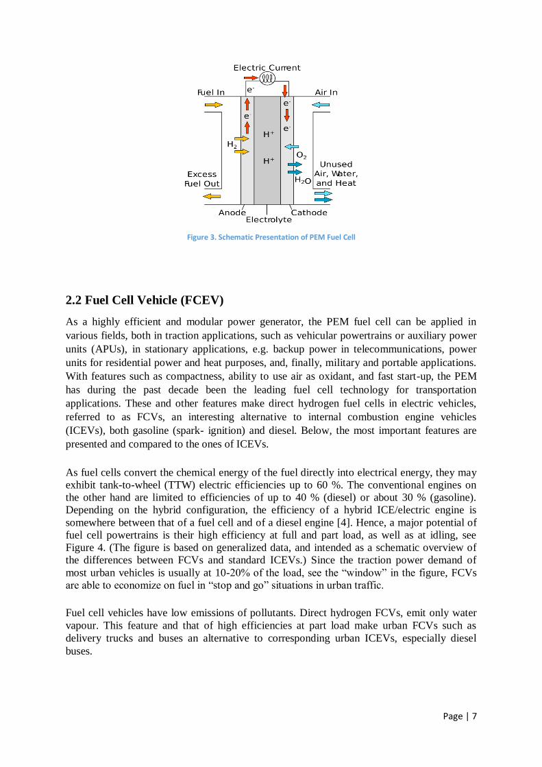
Figure 3 shows a schematic presentation of a PEM fuel cell. In operation, the anode is
supplied with hydrogen and the cathode with air. In the presence of the catalyst at the anode,
hydrogen molecules dissociate into free electrons and protons. The electrons are conducted as
usable current through the external circuit, while the protons migrate with water molecules
through the membrane electrolyte to the cathode. On the cathode side, oxygen from the air,
electrons from the external circuit and protons combine to form water and heat, thus
completing the total reaction.
Anode Reaction : H2 2H+ + 2e
-
Cathode Reaction: 1/2O2 +2H+
+ 2e- H2O
Total Reaction : H2 + 1/2O2 H2O
Page | 7
Figure 3. Schematic Presentation of PEM Fuel Cell
2.2 Fuel Cell Vehicle (FCEV)
As a highly efficient and modular power generator, the PEM fuel cell can be applied in
various fields, both in traction applications, such as vehicular powertrains or auxiliary power
units (APUs), in stationary applications, e.g. backup power in telecommunications, power
units for residential power and heat purposes, and, finally, military and portable applications.
With features such as compactness, ability to use air as oxidant, and fast start-up, the PEM
has during the past decade been the leading fuel cell technology for transportation
applications. These and other features make direct hydrogen fuel cells in electric vehicles,
referred to as FCVs, an interesting alternative to internal combustion engine vehicles
(ICEVs), both gasoline (spark- ignition) and diesel. Below, the most important features are
presented and compared to the ones of ICEVs.
As fuel cells convert the chemical energy of the fuel directly into electrical energy, they may
exhibit tank-to-wheel (TTW) electric efficiencies up to 60 %. The conventional engines on
the other hand are limited to efficiencies of up to 40 % (diesel) or about 30 % (gasoline).
Depending on the hybrid configuration, the efficiency of a hybrid ICE/electric engine is
somewhere between that of a fuel cell and of a diesel engine [4]. Hence, a major potential of
fuel cell powertrains is their high efficiency at full and part load, as well as at idling, see
Figure 4. (The figure is based on generalized data, and intended as a schematic overview of
the differences between FCVs and standard ICEVs.) Since the traction power demand of
most urban vehicles is usually at 10-20% of the load, see the “window” in the figure, FCVs
are able to economize on fuel in “stop and go” situations in urban traffic.
Fuel cell vehicles have low emissions of pollutants. Direct hydrogen FCVs, emit only water
vapour. This feature and that of high efficiencies at part load make urban FCVs such as
delivery trucks and buses an alternative to corresponding urban ICEVs, especially diesel
buses.

Page | 8
Figure 4. The Efficiency of different Technologies as function of load
Fuel cells Exhibits high power densities. This means that the fuel cells can be made compact
and thus improve the powertrains packaging in a vehicle. In addition, the fuel cell concept is
quite simple and fuel cells contain only a few moving parts. This means that the cost for mass
production and maintenance has a potential to be reduced over time.
Fuel cells have a modular design, which entails that, without appreciably affecting the
electric efficiency; the power output of the fuel cell stack can vary from a few Watts up to
MW-size. While the stack size is easily changed, it should be noted that the size of the
auxiliary system is not as easily changed, typically requiring completely new components.
In contrast to ICEs, the fuel cell technology enables low noise and vibration operation, even
in high power demand situations such as rapid acceleration.
2.3 Fuel Cell System
A successful operation of a fuel cell stack requires finely tuned conditions provided by an
auxiliary system. The power load of the auxiliary system can be significant, up to 20 % of the
fuel cell system gross power output, where the main parasitic load usually is the air
management system. Figure 5 shows a simplified example of a fuel cell powertrain where the
main components are:
Fuel cell stack
Air management system with a compressor or blower
Water management system with humidifiers
Heat management system with a cooling circuit connected to heat exchangers and
vehicle cabin radiator
Electrical power conditioners

Page | 9
Control system
Figure 5. Diagrammatic representation of simple Fuel Cell Powertrain
Whereas figure 6. Shows the detailed representation of auxiliary components in fuel cell.
Figure 6. Fuel Cell with its Auxiliary Components

Page | 10
A typical fuel cell stack operates in the temperature range of 60 - 80 °C. Higher operating
temperatures, above 100 ° C, would facilitate heat transfer, i.e. simplifying the cooling of the
stack, and reduce the CO poisoning risk, but currently there are material limitations that
prevent it.
2.3.1 Water Management
A water management system is needed to humidify the reactants for fuel cells operating
temperature above 60 °C. To ensure adequate conductivity and long life of the membrane
must be supplied in sufficient amounts and distributed in a homogeneous way. There must be
an appropriate approach to avoid the flooding or water blocking the pores of the electrodes.
A water balances, i.e. the amount of condensed water equals the amount of water needed for
humidification, is an important feature in automotive applications. In order for fuel cell
system to be water self-sustaining, therefore, the water management system also contains
equipment to condense the exhaust flows and collect and re-use the water.
The way the humidification is performed varies, ranging from external humidification, e.g.
direct water injection and enthalpy wheels, internal humidification such as using wicks or self
humidification, to no humidification at all. Removing or minimizing the external
humidification would simplify the fuel cell system in terms of space and heat supply.
However, the control of internal humidification has proven to be difficult and then no
humidification is also reported to increase the fuel cell system weight and consume more
power.
2.3.2 Air Management
The fuel cell stack is supplied with intake air by a blower or a compressor, depending on the
desired operating pressure. Pressurised system allows a smaller and more efficient fuel cell
stack, although to the cost of the compressor power requirements. Also, the efficiency at low
speeds and the compressor may behave abnormally. The operating pressure of a fuel cell
stack is normally between atmospheric pressure to 3 bars. The turbocharger can also be
effective as compared to normal compressor.
2.3.3 Heat Management
The electric efficiency of fuel cell is up to 60% which means the remainder of the input
energy is lost as heat. In order to regulate the constant temperature and stability of fuel cell
stack, the waste energy developed in the fuel cell is moved to a cooling point. The heat
rejected to the cooling circuit can be used within the system. Proper size of heat exchanger is
important as this system tends to be bulky.
2.3.4 Fuel Cell Hybrid Vehicle
As appeared in Figure 5, the fuel cell conveys energy to the electric drive by means of a
DC/AC inverter. In an arrangement fuel cell hybrid powertrain, a vitality support in addition
to a DC/DC converter is actualized into the energy unit powertrain. This additional power
source can be a battery, flywheel or supercapacitor. In this work, just arrangement of fuel cell
hybrid vehicles utilizing lithium-ion battery packs as power source is considered.

Page | 11
A hybridization of an energy component vehicle may involve a few advantages, regardless of
included multifaceted nature, weight and cost. It is demonstrated that hybridization enhances
the TTW productivity by 10-20 %. With an energy cushion, the braking energy of the vehicle
can be recuperated, and can be utilized to decrease the vehicle fuel utilization. For instance,
productivity additions of around 25 % might be expert in urban cycles with regenerative
braking for fuel cell transports. The beneficial outcomes of regenerative braking are reliant on
the obligation cycle utilized. While the advantages of hybridization are shown in duty cycles
with low power prerequisites, this is not as a matter of course the situation in duty cycles with
high power requests. It is additionally recommended that the hybridization will enhance the
FCV's snappy start-up capacity in cool atmospheres, with a energy pack giving the
underlying start-up force until the fuel cell is warmed up and completely operational.
The execution models set by ICEVs have ended up benchmarks for FCVs. The clients expect
the same execution of a FCV as an ICEV, under broadly shifting working conditions, e.g.
duty cycles, encompassing conditions, for example, nearby atmosphere with changing
temperature and humidity and elevation. To achieve these objectives, a great control
methodology, i.e. power-adjusting of the fuel cell and the energy cushion frameworks, and an
appropriate dimensioning of fuel cell and vehicle parts are fundamental.
2.4 Status of Fuel Cell Vehicles
The concern in PEM fuel cell vehicles increased in the 1990s. The giant automakers, like
GM, Ford, Nissan, Toyota, Honda, Hyundai, Mercedes, TATA, have active fuel cell
programmes. Initially, fuel cell vehicle development started in U.S.A. and later on it has been
spread worldwide including Europe, China, and India.
Today, fuel cell PEM fuel cell technology is used in many transportation mediums like
Cars
Buses
Forklifts
Motorcycle
Airplanes
Boats
Submarines
Trams
In, India TATA motors are majorly working on development on fuel cell vehicles and they
also showcased their fuel cell Bus and Light Commercial Vehicle in the 2008 and 2016,
AutoExpo, New Delhi. In the year 2016, Hyundai also showcased its fuel cell technology in
India.
The table 3, below showcases the list of fuel cell vehicle models came under production since
1990 till date.
Page | 12
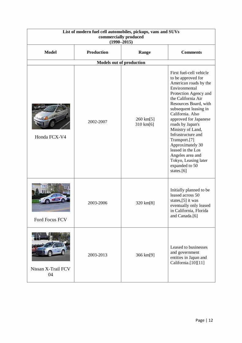
List of modern fuel cell automobiles, pickups, vans and SUVs
commercially produced
(1990–2015)
Model Production Range Comments
Models out of production
Honda FCX-V4
2002-2007 260 km[5]
310 km[6]
First fuel-cell vehicle
to be approved for American roads by the
Environmental
Protection Agency and the California Air
Resources Board, with
subsequent leasing in California. Also
approved for Japanese
roads by Japan's
Ministry of Land, Infrastructure and
Transport.[7]
Approximately 30 leased in the Los
Angeles area and
Tokyo, Leasing later
expanded to 50 states.[6]
Ford Focus FCV
2003-2006 320 km[8]
Initially planned to be
leased across 50
states,[5] it was eventually only leased
in California, Florida
and Canada.[6]
Nissan X-Trail FCV
04
2003-2013 366 km[9]
Leased to businesses and government
entities in Japan and
California.[10][11]
Page | 13
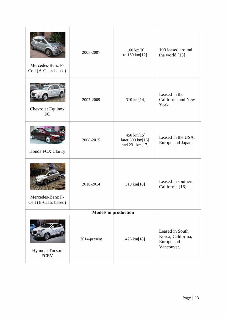
Mercedes-Benz F-
Cell (A-Class based)
2005-2007 160 km[8]
to 180 km[12]
100 leased around
the world.[13]
Chevrolet Equinox
FC
2007-2009 310 km[14]
Leased in the
California and New
York.
Honda FCX Clarity
2008-2015
450 km[15]
later 390 km[16]
and 231 km[17]
Leased in the USA,
Europe and Japan.
Mercedes-Benz F-
Cell (B-Class based)
2010-2014 310 km[16] Leased in southern
California.[16]
Models in production
Hyundai Tucson
FCEV
2014-present 426 km[18]
Leased in South
Korea, California,
Europe and
Vancouver.
Page | 14
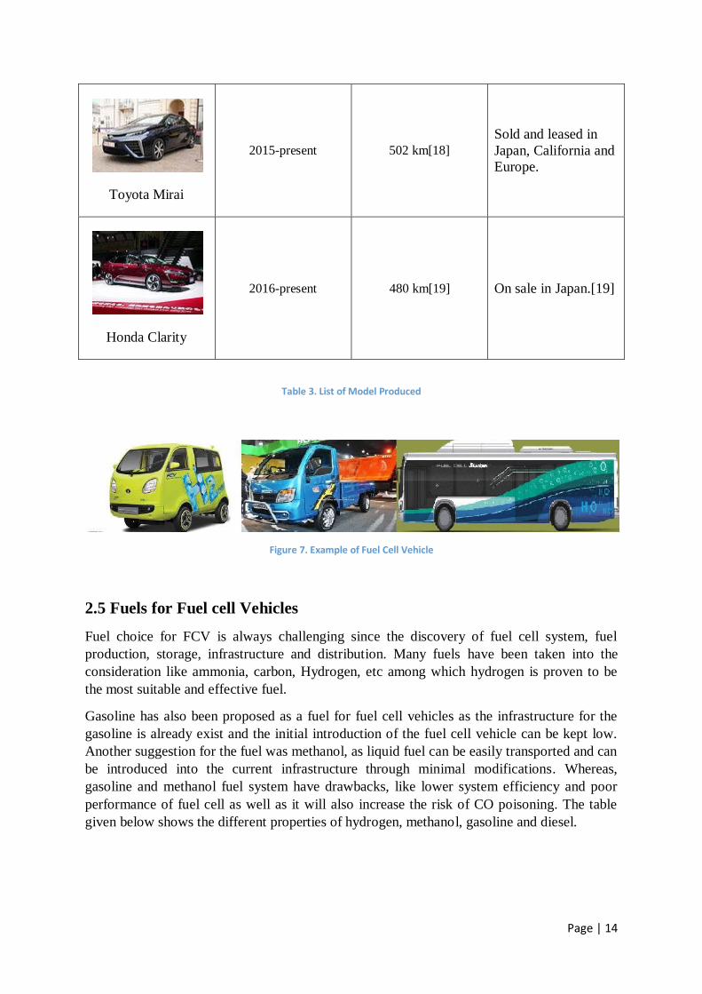
Toyota Mirai
2015-present 502 km[18]
Sold and leased in
Japan, California and
Europe.
Honda Clarity
2016-present 480 km[19] On sale in Japan.[19]
Table 3. List of Model Produced
Figure 7. Example of Fuel Cell Vehicle
2.5 Fuels for Fuel cell Vehicles
Fuel choice for FCV is always challenging since the discovery of fuel cell system, fuel
production, storage, infrastructure and distribution. Many fuels have been taken into the
consideration like ammonia, carbon, Hydrogen, etc among which hydrogen is proven to be
the most suitable and effective fuel.
Gasoline has also been proposed as a fuel for fuel cell vehicles as the infrastructure for the
gasoline is already exist and the initial introduction of the fuel cell vehicle can be kept low.
Another suggestion for the fuel was methanol, as liquid fuel can be easily transported and can
be introduced into the current infrastructure through minimal modifications. Whereas,
gasoline and methanol fuel system have drawbacks, like lower system efficiency and poor
performance of fuel cell as well as it will also increase the risk of CO poisoning. The table
given below shows the different properties of hydrogen, methanol, gasoline and diesel.
Page | 15
Fuel Hydrogen Methanol Gasoline Diesel
Chemical formula (phase) H2(g, l) CH3OH(l) CnH1.87n(l) CnH1.8n(l)
Molecular
weight 2.02 32.0 ~110 ~170
Energy per unit mass [MJ/Kg] 120.0 20.0 44.0 42.5
Energy per unit
mol [MJ/mol] 241.8 640.8 4840 7225
Energy per unit volume [MJ/m
3] 10.8 15.8 33.0 36.5
Density [kg/m3] 0.09
2 (g), 790 720-780 840-880
Diffusion coefficient
[cm2/s] 0.61 0.0042 0.05 -
Flammability limits 4-75 6-36.5 1-7.6 -
Table 4. Shows the properties of Hydrogen, Methanol, Gasoline and Diesel
2.5.1 Hydrogen as Vehicle Fuel
The best alternative for ammonia, gasoline, diesel, etc. is to use Hydrogen as a fuel in fuel
cell system. It is very convenient in terms of cost as well as system complexity of producing
hydrogen onboard. With the help of this hydrogen can be produced at a central processing
station from where it can be supplied to different hydrogen filling stations.
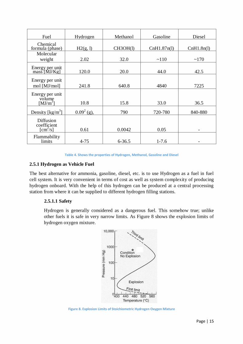
2.5.1.1 Safety
Hydrogen is generally considered as a dangerous fuel. This somehow true; unlike
other fuels it is safe in very narrow limits. As Figure 8 shows the explosion limits of
hydrogen oxygen mixture.
Figure 8. Explosion Limits of Stoichiometric Hydrogen Oxygen Mixture
Page | 16
Whereas, hydrogen is very light gas which increases the risk of accumulation of gas
among the roof in case of leaks. Therefore, slow leaks in enclosed area are greatest
risks. Odorant can be added as in natural gases but it will lead to introduction of
sulphur in the system which can choke the supply of fuel into the system.
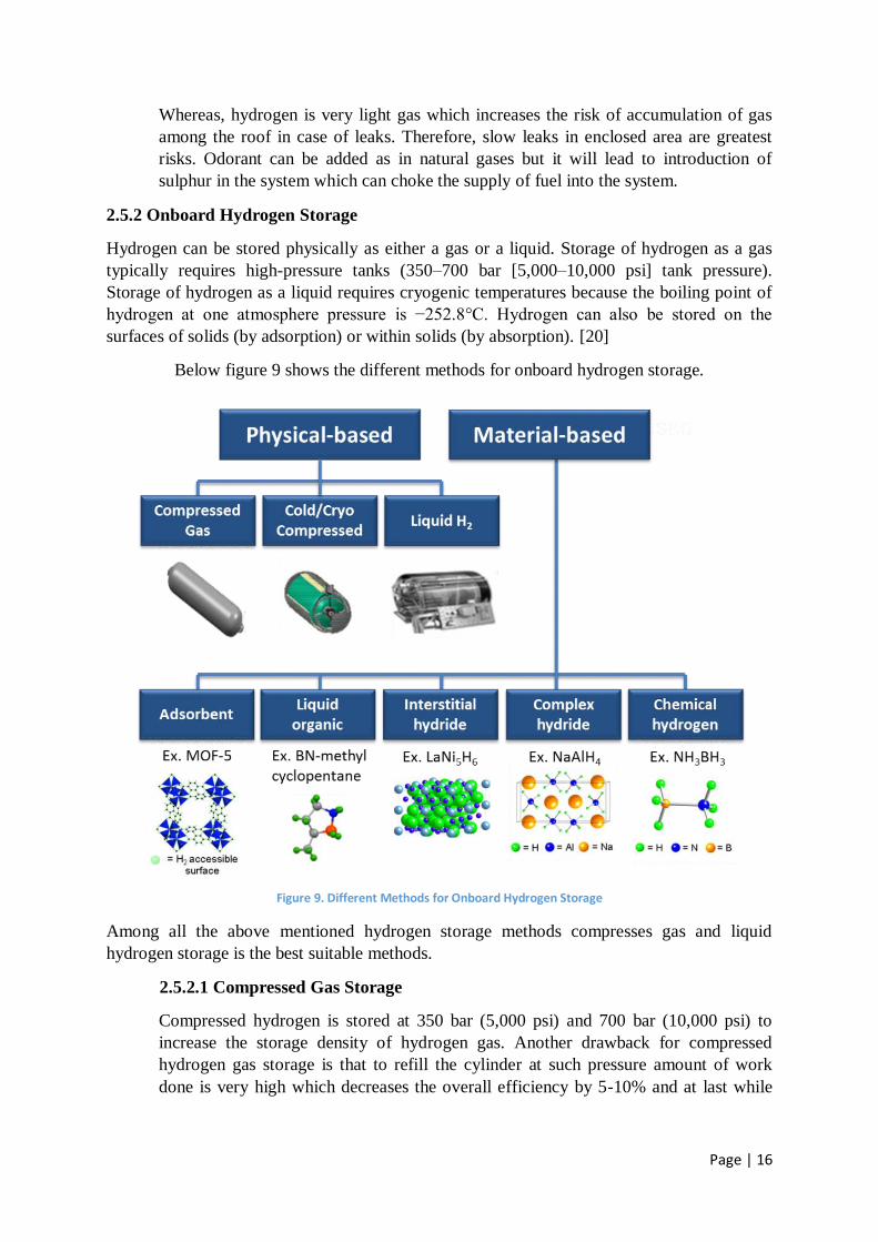
2.5.2 Onboard Hydrogen Storage
Hydrogen can be stored physically as either a gas or a liquid. Storage of hydrogen as a gas
typically requires high-pressure tanks (350–700 bar [5,000–10,000 psi] tank pressure).
Storage of hydrogen as a liquid requires cryogenic temperatures because the boiling point of
hydrogen at one atmosphere pressure is −252.8°C. Hydrogen can also be stored on the
surfaces of solids (by adsorption) or within solids (by absorption). [20]
Below figure 9 shows the different methods for onboard hydrogen storage.
Figure 9. Different Methods for Onboard Hydrogen Storage
Among all the above mentioned hydrogen storage methods compresses gas and liquid
hydrogen storage is the best suitable methods.
2.5.2.1 Compressed Gas Storage
Compressed hydrogen is stored at 350 bar (5,000 psi) and 700 bar (10,000 psi) to
increase the storage density of hydrogen gas. Another drawback for compressed
hydrogen gas storage is that to refill the cylinder at such pressure amount of work
done is very high which decreases the overall efficiency by 5-10% and at last while

Page | 17
filling up the cylinder the temperature will also rise due to which an additional
cooling system is also required which also reduces the efficiency of the vehicle.
2.5.2.2 Liquid Hydrogen Storage
Cryogenic as well as very expensive technology is required to store the hydrogen in
liquid state as hydrogen comes to liquid state at a temperature of 20 K which requires
very highly insulated tanks. Another drawback of liquid storage is that if the car is left
unattended for a long period it will lose all its hydrogen as creating a completely
insulated tank is very difficult. As well as some preheating of hydrogen is required to
supply it into the fuel cell. Preheating of hydrogen can be achieved by using ambient
air or using this hydrogen into the air conditioner heat exchanger. The below
mentioned graphs shows the preheating requirements for the fuel released from the
liquid hydrogen tank.
Figure 10. Preheating Requirements for the fuel supplied from liquid hydrogen tank in K
2.5.3 Requirement for Implementation of Fuel Cell Vehicle
Figure 11 shows all the requirement for the successful implementation of fuel cell vehicle and
the picture is itself self explanatory.
Figure 11. Requirements for successful Implementation of Fuel Cell Vehicles

Page | 18
≈
Chapter Three
≈
Page | 19
3. Design of Fuel Cell Vehicle
3.1 Design of Vehicle
Here we are trying to design of the FCHEV three wheeler by taking the reference of Bajaj RE
4S three wheeler auto. According to the initial analysis it is came into the knowledge that an
8 HP motor is required to drive the three wheeler and to fulfil its power requirement an 6 kW
fuel cell energy system is required.
3.1.1 Background and Motivation
3- Wheelers play a very important role in developing countries like India. As they are
considered as the major contributor to the public transportation system in congested
cities like Mumbai, Kolkata, Delhi, etc. They are the most economical source of
transport in comparison to the taxis. Therefore, they also play an major role in
pollution. As the oil prices are also rising, it is an appropriate time to introduce a
cleaner and economical alternative source of these vehicles.
3.2 Design
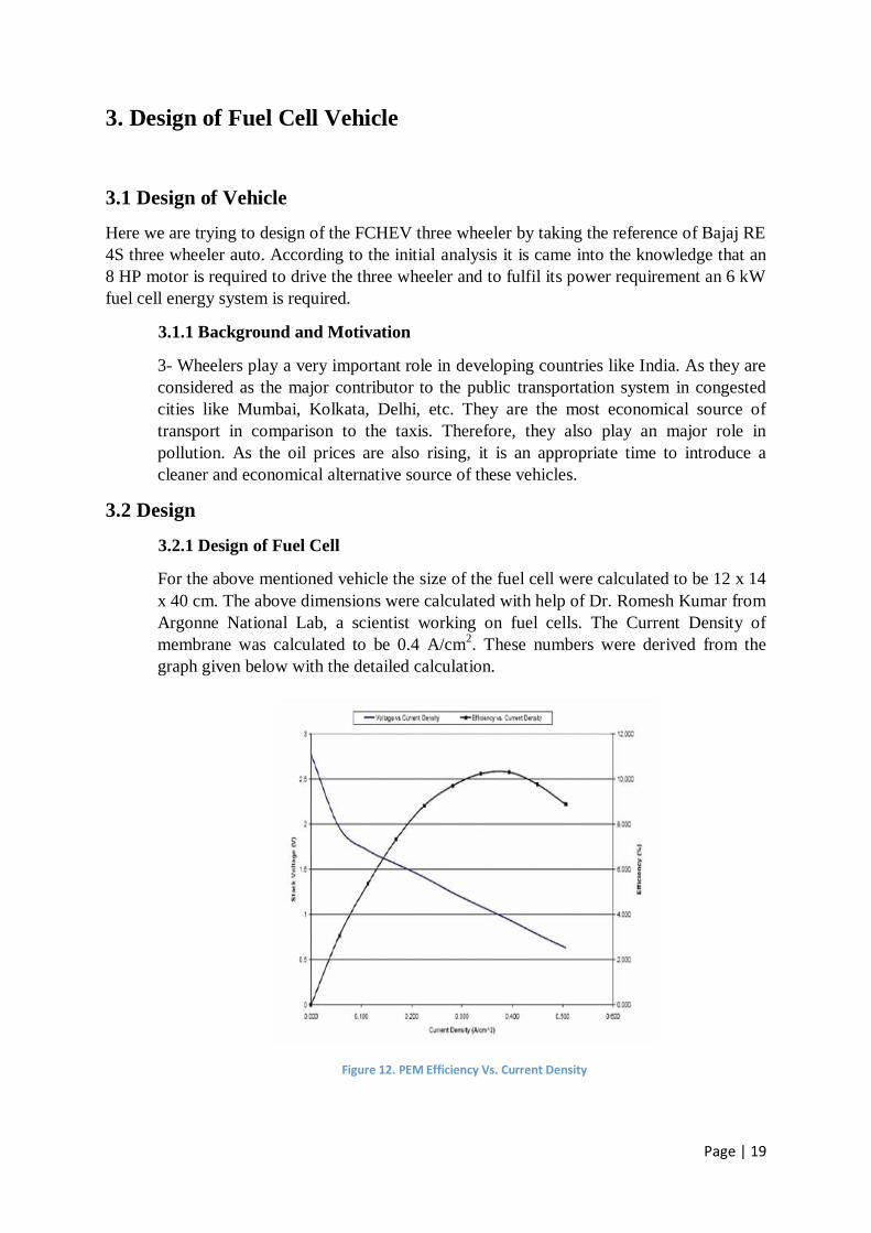
3.2.1 Design of Fuel Cell
For the above mentioned vehicle the size of the fuel cell were calculated to be 12 x 14
x 40 cm. The above dimensions were calculated with help of Dr. Romesh Kumar from
Argonne National Lab, a scientist working on fuel cells. The Current Density of
membrane was calculated to be 0.4 A/cm2. These numbers were derived from the
graph given below with the detailed calculation.
Figure 12. PEM Efficiency Vs. Current Density
Page | 20
The required power is estimated to be 6 kW and charge density of 0.4 A/cm2. On
choosing the appropriate size of 7 x 9 cm leads to current, I = .04 x 63 = 25 A. Now,
V = P/I i.e. V = 6000/25, V = 240. Assuming 100 cells of 2.4 V each. For 100 cell
stack, a volume of 12 x 14 x 40 cm3 is obtained.
3.2.2 NI-MH Batteries
Currently available nickel metal hydride batteries with specific energy and power
levels intermediate to those required for power assist hybrid electric vehicles and pure
battery electric vehicles respectively, come close to meet the performance of
conventional vehicles[21-22].NI-MH battery can discharge rapidly and oftenly due to
which it is best suitable for congested traffic of Indian cities.
For 6 KW, 48 V is determined as the appropriate voltage for the motor and the
maximum amount of current calculated is IMax = P/V, = 6000/48, IMax = 120 A.
according to the above mentioned voltage and the cell voltage calculated in the
previous section then total 20 cells are required in series and above all NI-MH battery
can generate so much current that it can satisfy the need incase of peak power
requirement of 6 KW.
3.3 Specifications of Bajaj Three Wheeler [23]
Power 6.00Kw@5000rpm
Torque 16.7 N.m@4500rpm
Cubic Capacity 198.88 cc
Transmission 4 forward + 1 reverse gear
Clutch Wet multidisc type
Kerb weight 337 kg
Wheel Base 2000 mm
Overall width 1300 mm
Overall length 2635 mm
Overall Height 1704 mm
Gradeability 19%
Table 5. Shows the technical specification of the Baja RE 4S Three Wheeler Auto
Page | 21
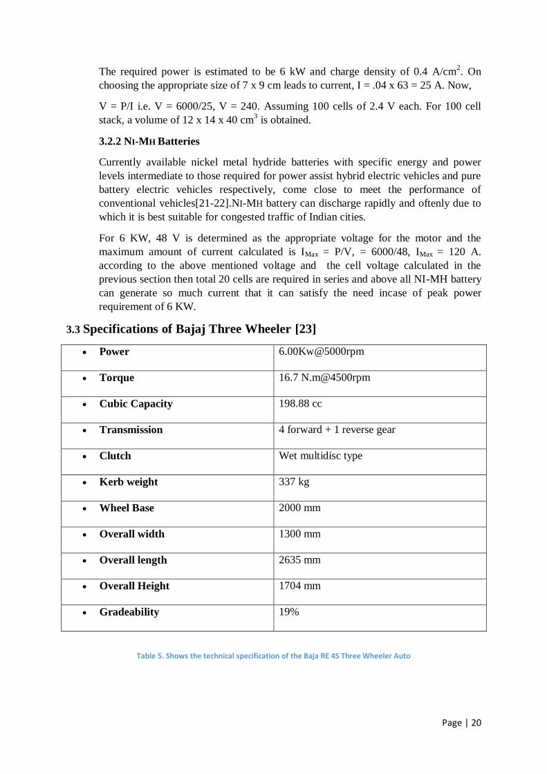
Figure 13. Bajaj RE 4S Three Wheeler Auto
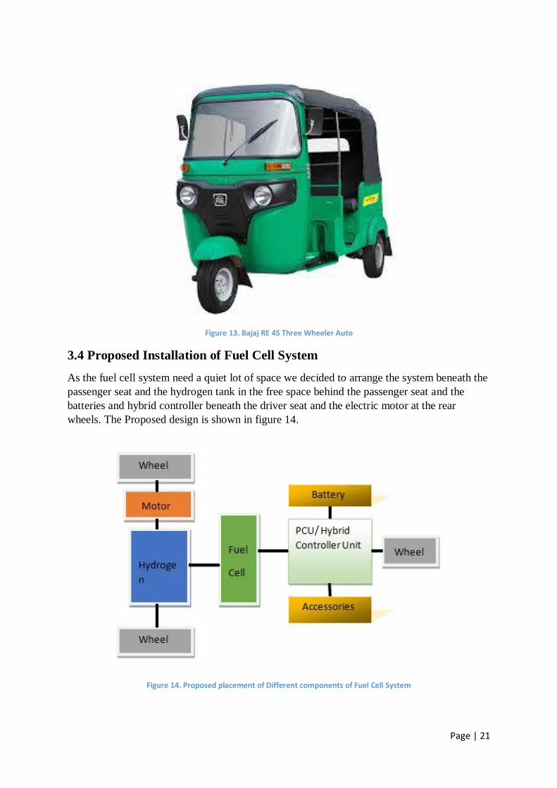
3.4 Proposed Installation of Fuel Cell System
As the fuel cell system need a quiet lot of space we decided to arrange the system beneath the
passenger seat and the hydrogen tank in the free space behind the passenger seat and the
batteries and hybrid controller beneath the driver seat and the electric motor at the rear
wheels. The Proposed design is shown in figure 14.
Figure 14. Proposed placement of Different components of Fuel Cell System
Page | 22
The volume of each component behind the passenger seat was calculated by the given
dimension. After the calculations the hydrogen tank, fuel cell and battery accumulate approx.
15 litre (915.36 in3), 6.5 litre (397.61 in
3), 57 litre (3,468.71 in
3)
respectively. So, the total
space required is 78.35 litre (4,781.68 in3)
and the total space calculate behind the passenger
seat is 259 litre (15,819.51 in3). After considering the packing factor and space requires for
other equipments the total space left will be 15,819.51- (4,781.68 x 3) = 24 litre (1,474.47
in3). Hence it shows that there is an appropriate space left for passenger's luggage.
3.5 Simulation & Results
Developing fuel cell and hybrid electric vehicles (HEVs) requires accurate, flexible
simulation tools. Argonne National Lab undertook a Collaborative effort to further develop
the power train system analysis toolkit (PSAT) under the direction of and with contributions
from ford, General Motors and DiamlerChrysler. [24] PSAT is simulation software that
allows users to simulate predetermined configurations of different vehicle types or design
new hybrid vehicles. It predicts fuel economy emissions and the performance of vehicle
taking into account transient behaviour and control system characteristics. [24]
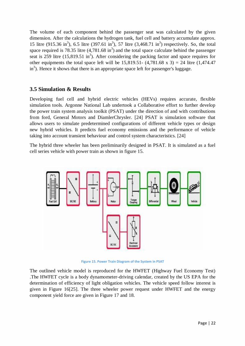
The hybrid three wheeler has been preliminarily designed in PSAT. It is simulated as a fuel
cell series vehicle with power train as shown in figure 15.
Figure 15. Power Train Diagram of the System in PSAT
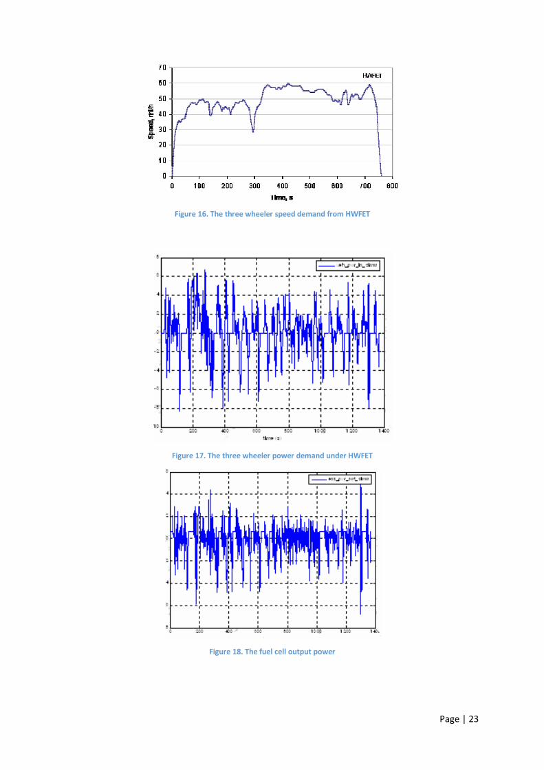
The outlined vehicle model is reproduced for the HWFET (Highway Fuel Economy Test)
.The HWFET cycle is a body dynamometer-driving calendar, created by the US EPA for the
determination of efficiency of light obligation vehicles. The vehicle speed follow interest is
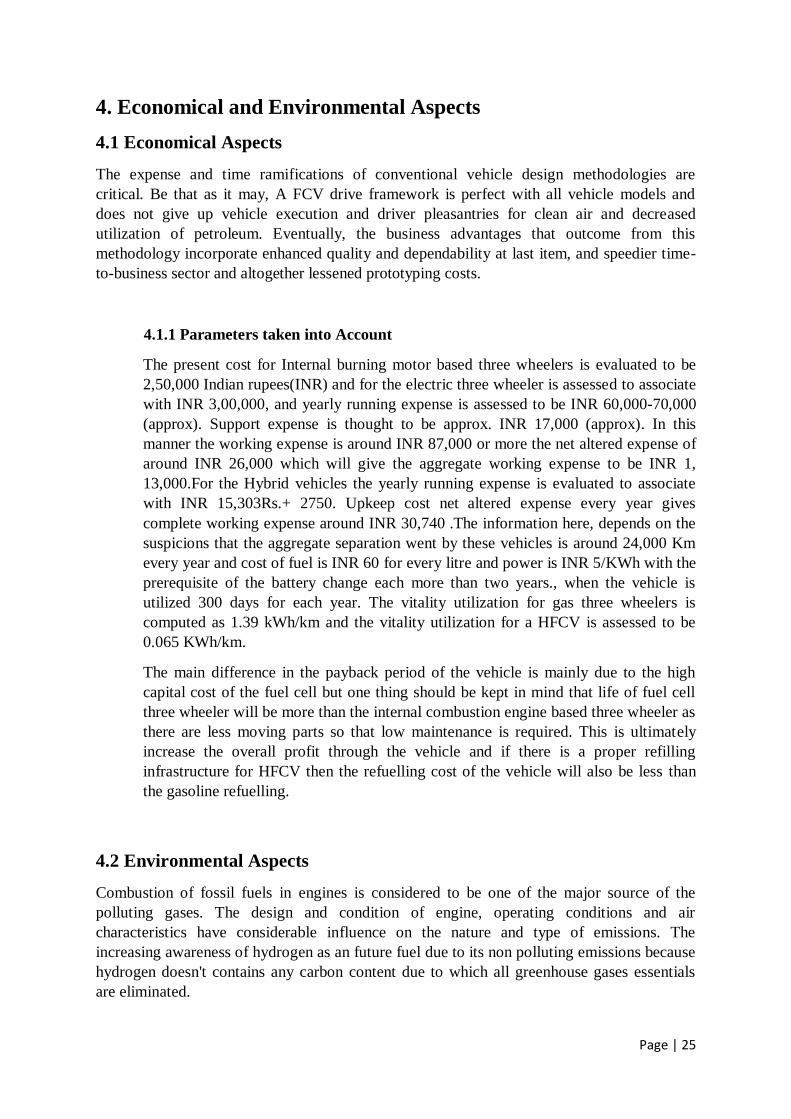
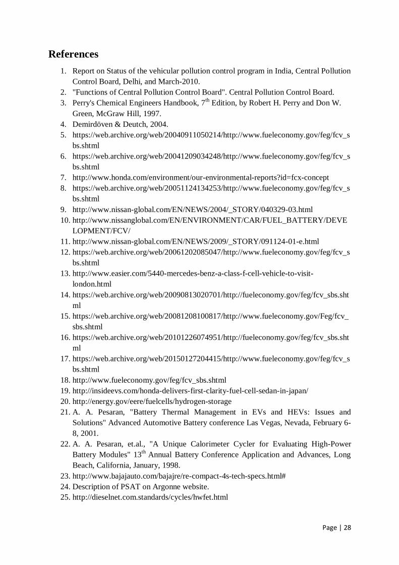
given in Figure 16[25]. The three wheeler power request under HWFET and the energy
component yield force are given in Figure 17 and 18.
Page | 23
Figure 16. The three wheeler speed demand from HWFET
Figure 17. The three wheeler power demand under HWFET
Figure 18. The fuel cell output power

Page | 24
≈
Chapter Four
≈
Page | 25
4. Economical and Environmental Aspects
4.1 Economical Aspects
The expense and time ramifications of conventional vehicle design methodologies are
critical. Be that as it may, A FCV drive framework is perfect with all vehicle models and
does not give up vehicle execution and driver pleasantries for clean air and decreased
utilization of petroleum. Eventually, the business advantages that outcome from this
methodology incorporate enhanced quality and dependability at last item, and speedier time-
to-business sector and altogether lessened prototyping costs.
4.1.1 Parameters taken into Account
The present cost for Internal burning motor based three wheelers is evaluated to be
2,50,000 Indian rupees(INR) and for the electric three wheeler is assessed to associate
with INR 3,00,000, and yearly running expense is assessed to be INR 60,000-70,000
(approx). Support expense is thought to be approx. INR 17,000 (approx). In this
manner the working expense is around INR 87,000 or more the net altered expense of
around INR 26,000 which will give the aggregate working expense to be INR 1,
13,000.For the Hybrid vehicles the yearly running expense is evaluated to associate
with INR 15,303Rs.+ 2750. Upkeep cost net altered expense every year gives
complete working expense around INR 30,740 .The information here, depends on the
suspicions that the aggregate separation went by these vehicles is around 24,000 Km
every year and cost of fuel is INR 60 for every litre and power is INR 5/KWh with the
prerequisite of the battery change each more than two years., when the vehicle is
utilized 300 days for each year. The vitality utilization for gas three wheelers is
computed as 1.39 kWh/km and the vitality utilization for a HFCV is assessed to be
0.065 KWh/km.
The main difference in the payback period of the vehicle is mainly due to the high
capital cost of the fuel cell but one thing should be kept in mind that life of fuel cell
three wheeler will be more than the internal combustion engine based three wheeler as
there are less moving parts so that low maintenance is required. This is ultimately
increase the overall profit through the vehicle and if there is a proper refilling
infrastructure for HFCV then the refuelling cost of the vehicle will also be less than
the gasoline refuelling.
4.2 Environmental Aspects
Combustion of fossil fuels in engines is considered to be one of the major source of the
polluting gases. The design and condition of engine, operating conditions and air
characteristics have considerable influence on the nature and type of emissions. The
increasing awareness of hydrogen as an future fuel due to its non polluting emissions because
hydrogen doesn't contains any carbon content due to which all greenhouse gases essentials
are eliminated.

Page | 26
≈
Chapter Five
≈

Page | 27
5. Conclusion
The fuel cell technology is an appropriate technique to reduce the energy demand of the
automobile sector. To be accepted by the end-users, fuel cell vehicles need to be more
economical and will have to perform better in comparison to ICE vehicles. The acceptance of
fuel cell vehicle also depends upon the availability of the fuel.
In, this work an effort has been made to understand, state of art of fuel cell vehicles globally
and in India. Here, a design of a fuel cell hybrid three wheeler vehicle has been carried out.
Having low or we can say no greenhouse gas emissions
Specification of the Designed Vehicle:
Motor 8 HP
Fuel Cell Power 6 kW
Size of Fuel Cell 12 x 14 x 40 cm (6.5 litre)
Battery 20 cell, 48 volt
Volume of Hydrogen Tank 15 litre
Page | 28
References
1. Report on Status of the vehicular pollution control program in India, Central Pollution
Control Board, Delhi, and March-2010.
2. "Functions of Central Pollution Control Board". Central Pollution Control Board.
3. Perry's Chemical Engineers Handbook, 7th Edition, by Robert H. Perry and Don W.
Green, McGraw Hill, 1997.
4. Demirdöven & Deutch, 2004.
5. https://web.archive.org/web/20040911050214/http://www.fueleconomy.gov/feg/fcv_s
bs.shtml
6. https://web.archive.org/web/20041209034248/http://www.fueleconomy.gov/feg/fcv_s
bs.shtml
7. http://www.honda.com/environment/our-environmental-reports?id=fcx-concept
8. https://web.archive.org/web/20051124134253/http://www.fueleconomy.gov/feg/fcv_s
bs.shtml
9. http://www.nissan-global.com/EN/NEWS/2004/_STORY/040329-03.html
10. http://www.nissanglobal.com/EN/ENVIRONMENT/CAR/FUEL_BATTERY/DEVE
LOPMENT/FCV/
11. http://www.nissan-global.com/EN/NEWS/2009/_STORY/091124-01-e.html
12. https://web.archive.org/web/20061202085047/http://www.fueleconomy.gov/feg/fcv_s
bs.shtml
13. http://www.easier.com/5440-mercedes-benz-a-class-f-cell-vehicle-to-visit-
london.html
14. https://web.archive.org/web/20090813020701/http://fueleconomy.gov/feg/fcv_sbs.sht
ml
15. https://web.archive.org/web/20081208100817/http://www.fueleconomy.gov/Feg/fcv_
sbs.shtml
16. https://web.archive.org/web/20101226074951/http://fueleconomy.gov/feg/fcv_sbs.sht
ml
17. https://web.archive.org/web/20150127204415/http://www.fueleconomy.gov/feg/fcv_s
bs.shtml
18. http://www.fueleconomy.gov/feg/fcv_sbs.shtml
19. http://insideevs.com/honda-delivers-first-clarity-fuel-cell-sedan-in-japan/
20. http://energy.gov/eere/fuelcells/hydrogen-storage
21. A. A. Pesaran, "Battery Thermal Management in EVs and HEVs: Issues and
Solutions" Advanced Automotive Battery conference Las Vegas, Nevada, February 6-
8, 2001.
22. A. A. Pesaran, et.al., "A Unique Calorimeter Cycler for Evaluating High-Power
Battery Modules" 13th
Annual Battery Conference Application and Advances, Long
Beach, California, January, 1998.
23. http://www.bajajauto.com/bajajre/re-compact-4s-tech-specs.html#
24. Description of PSAT on Argonne website.
25. http://dieselnet.com.standards/cycles/hwfet.html
Page | 29
Bibliography
1. Mohammad Farooque, and Hans C.Maru, “Fuel Cells-The Clean and Efficient Power Generators,” Proceedings of the IEEE, Vol.89, No.2.December 2001, pp.1819-1829.
2. Michael W. Ellis, Michael R. Von Spakovsky, and Douglas J. Nelson, “Fuel Cell Systems: Efficient, Flexible Energy Conversion for the 21st Century,” Proceedings of the IEEE, Vol.89, No.12, Dec.2001 pp.1808-1818.
3. R. Ramakumar, and P. Chiradeja, “Distributed generation and renewable energy systems,” In Proc. 2002, 37
th
4. Intersociety Energy Conversion Engineering Conf., IECEC-2002, pp. 716-724.
5. M. Hashem Nehrir, Caisheng Wang, and Steven R. Shaw, “Fuel Cells: Promising Devices for Distributed Generation”, IEEE Power & Energy, Vol.4, Jan/Feb. 2006, pp.47-53.
6. Jaferson M. Correa, Felix A. Ferret, Luciane N. Canha, and Marcelo G. Simoes, “An Electrochemical based Fuel Cell Model Suitable for Electrical Engineering Automation Approach,” IEEE Trans. On Indus. Electron., Vol. 51, 2004, pp.1103-1112.
7. J. B. Jia, Y. T. Cham, Y .Wang, and Frank Lewis, “The Electrical Dynamic Response Study of PEMFC as a Backup Power Supply,” 2007 IEEE International Conference on Control and Automation, May30-June1 2007, pp. 1156-1160.
8. Jin-Woo Jung, and Ali Keyhani, “Fuel Cell Based Distributed Generation,” 12th International Middle-East Power System Conference, March 2008, pp. 610-616.
9. Mehdi Soltani, and S.M.T. Bathaee, “A new dynamic model considering effects of
Temperature, pressure and internal resistance for PEM fuel cell power modules,” 3rd
International Conference on Electric Utility Deregulation and Restructuring and
Power Technologies, April 2008, pp. 2757-2762.
10. J.M. Correa, F.A. Farret, V.A. Popov, and M.G. Simoes, “Sensitivity Analysis of the Modeling Parameters Used in Simulation of Proton Exchange Membrane Fuel Cells,” IEEE Trans. On Energy Conv., Vol.20, 2005, pp. 211-218.
11. Goce L. Arsov, “Improved Parametric Pspice Model of a PEM Fuel Cell,” 11th
International Conference on optimization of Electrical and Electronics Equipment, May 2008, pp. 203-208.
12. X. Yu, M. R. Starke, L. M. Tolbert, and B. Ozpineci, “Fuel cell power conditioning for electric power applications: a summary,” IET Electr. Power Appli., Vol.1, No.5, 2007, pp 643-656.
13. Troy A. Nergaard, Jeremy F. Ferrell, Leonard G. Leslie, and Jih Sheng Lai, “Design considerations for a 48V Fuel Cell to Split Single Phase Inverter System with Ultra capacitor Energy Storage,” in Power Electron. Specialists Conference, 2002, pp. 2007-2012.
14. Fuel Cell Hand Book, U.S. Dept. Of Energy, Office of Fossil Fuel, 7th ed., National Energy Technology Laboratory, West Virginia, Oct. 2000.

Page | 30
15. M. Tanrioven, and M. S. Alam, “Modeling, control, and power quality evaluation of PEM fuel cell-based power supply system for residential use,” IEEE Trans. on Indus. Appl., vol.42, No.6, Nov/Dec 2006, pp. 1582-1589.
16. K.W.E. Cheng, D. Sutanto, Y.L. Ho, and K.K. Law, “Exploring the Power
Conditioning System for Fuel Cell,” In 32nd
IEEE Annual Power Electronics
Specialists Conference, 2001, pp.2197-2202.
17. Shailendra Jain, Jin Jiang, Xinhong Huhang, and Srdjan Stvandic, “Single Stage Power Electronic Interface for a Fuel Cell Based Power Supply System,” IEEE Electric Power Conference, Oct. 2007, pp. 201-206.
18. N. Mohan, T.M. Undeland, and W.P. Robbins, “Power Electronics Converters, Applications and Design,” 3rd ed. Jon Wiley & Sons, 2001.
19. B. Hasaneen, and Adel A. Elbaset Mohammed, “Design and simulation of dc/dc boost converter,” 12
th International Middle East Power System Conference, 12-15 Mar
2008, pp 335-340.
20. Frederik M.L.L. De Belie, David M. Van de Sype, Koen De Gusseme, wounter R.A.
Ryckaert, and Jan A.A. Melkebeek, “Digitally controlled boost PFC converter with
improved output voltage controller,” Journal of Electrical Engineering, Vol.89, 2007,
pp. 363-370.
21. U.S. Fuel Cell Council, “Fuel cell power for vehicles,” see http://www.usfcc.com/.
22. L. E. Lesster, “Fuel cell power electronics – managing a variable-voltage dc source in
a fixed-voltage ac world,” Fuel Cells Bulletin, no. 25, 2000.
23. J. M. Miller, “Power electronics in hybrid electric vehicle applications,” in Proc. 18th
IEEE Applied Power Electronics Conf., Miami Beach, FL, Feb. 2003, vol. 1, pp. 23-
29.
24. S. S. Williamson and A. Emadi, “Fuel cell applications in the automotive industry,” in
Proc. Electrical Manufacturing and Coil Winding Expo, Cincinnati, Ohio, Oct. 2002.
25. H. Moghbelli, K. Ganapavarapu, and R. Langari, “A comparative review of fuel cell
vehicles (FCVs) and hybrid electric vehicles (HEVs) – Part II,” in Proc. SAE Future
Transportation Technology Conf., Costa Mesa, CA, June 2003.
26. C. E. Thomas, B. D. James, F. D. Lomax, Jr., and I. F. Kuhn, Jr., “Societal impacts of
fuel options for fuel cell vehicles,” in Proc. SAE Fall Fuels and Lubricants Meeting
and Expo, San Francisco, CA, Oct. 1998.
27. J. F. Contandini, “Social cost comparison among fuel cell vehicle alternatives,” in Proc. 35
th IEEE Intersociety Energy Conversion Engineering Conf., Las Vegas, NV,
July 2000, pp. 1341-1351.
Page | 31
28. M. Q. Wang, “GREET 1.5 – transportation fuel-cycle model: methodology, use, and
results, ANL/ESD-39, Vol. 1,” Aug. 1999.
29. N. Brinkman, “Well-to-wheel energy consumption and greenhouse gas analysis,” U.S.
Environmental Protection Agency (EPA) Fuel Cells Workshop, Cincinnati, OH, June
2001.
30. H. Moghbelli, K. Ganapavarapu, R. Langari, and M. Ehsani, “A comparative review
of fuel cell vehicles (FCVs) and hybrid electric vehicles (HEVs) – Part I,” in Proc.
SAE Future Transportation Technology Conf., Costa Mesa, CA, June 2003.
31. G. Maggetto and J. Van Mierlo, “Electric and electric hybrid vehicle technology: a
survey,” in Proc. IEE Seminar on Electric, Hybrid, and Fuel Cell Vehicles, London,
UK, April 2000, pp. 1-11.
32. College of the Desert and Sunline Transit Agency, “Course manual on hydrogen fuel
cell engines and related technologies,” Dec. 2001, see http://www.ott.doe.gov/.
33. W. D. Jones, “Hybrids to the rescue,” IEEE Spectrum, vol. 40, no. 1, pp. 70-71, Jan.
2003.
34. F. A. Wyczalek, “Hybrid electric vehicles – year 2000,” in Proc. 35th IEEE
Intersociety Energy Conversion Engineering Conf., Las Vegas, NV, July 2000, vol. 1,
pp. 349-355. 35. Hill.March 20 2003 Glendale, CA. <www.micrometals.com>.
36. IRFPS3810 Datasheet, International Rectifier Corporation. April 26 2002 El
Segunda, CA. <www.irf.com>.
37. IXDD414CI Datasheet, IXYS Corporation. Santa Clara, CA.
<http://www.ixys.com>.
38. 30EPH03 Datasheet, Intemational Rectifier Corporation. May 2001 El
Segunda, CA. <www.irf.com>.
39. Anzicek, J., Berry, K.J., Hoff, C., Lemke, B., Lerner, S., Slota, G., Thompson, M.,
Ubong, E., Van Tiem, R., and Zang, P., 2004, Fuel Cell Hybrid Vehicle
Development at Kettering University, EMCW2004 Technical Conference CD ROM
ISBN Number 07803-7936-5, pp. 1-6.
40. NEXA Power Module User's Guide, MAN5100078, 2003, Ballard Power Systems,
Inc., p. 67.
41. Kaiser, K.L., 2005, Electromagnetic Compatibility Handbook, CRC Press, New York,
p. 15-203.
42. Anzicek, J. and Thompson, M., Power Converter and Control Interface for a GEM
Fuel Cell Vehicle, Proceedings of the 3rd International Conference on Fuel Cell
Science, Engineering and Technology, May 23-25, 2005, Ypsilanti, MI
43. T.Yokoyama, Y.Naganuma, K.Kuriyama, M.arimoto, "Development of the Fuel-cell
Hybrid Bus," SAE World congress 2003, 2003
44. M.Kizaki, H.Mizuno, Y.Miki, T.Takahashi, O.Oogami, "Development of Fuel-cell
Hybrid Vehicles in TOYOTA," EVS22, 2006.

Annexure A
A research Paper has been presented in the Poster Presentation of National Conference on
Carbon Materials 2015, organised by Indian Carbon Society & National Physical Laboratory.
Paper has been submitted for the publication and is pending with the organisation.
Fuel Cell Vehicle - Scope and Limitations
Harsh Gupta1*
, Vivek Verma2 and A.K. Jouhari
3
Amity School of Engineering and Technology,
Amity University Uttar Pradesh,
Lucknow Campus, Lucknow-226028
(*Correspondence E-mail: [email protected])
INTRODUCTION
Global air pollution is a serious problem. Most of this problem is caused by the use of fossil
fuels for transportation. Therefore, automobile manufacturers are looking for a more
promising and non-polluting source of energy which provides sufficient power while being
safe for the environment. At the same time a great deal of research and development on fuel
cells have taken place in finding an appropriate source of energy. Many researchers have
concluded that fuel cell can be an alternative source of energy for automobiles.
In this paper, we will discuss about the hybrid electric vehicles which are powered by Fuel
cell technology instead of conventional I.C. Engine which reduces the CO2 emissions. Here
we will promote Hydrogen as a fuel in fuel cell vehicles.
REVIEW
Fuel Cells
A fuel cell is a static energy conversion device that converts chemical energy of fuels directly
into electrical energy with some heat and water as its by-product [1].
There are basically five types of fuel cells:-
1. Proton Exchange Membrane Fuel Cell (PEMFC)
2. Phosphoric Acid Fuel Cell
3. Solid Oxide Fuel Cell
4. Hydrogen Oxygen Fuel Cell
5. Molten Carbonate Fuel Cell
Out of all the above, only Proton exchange membrane fuel cells are the most suitable for the
automobile applications as they operate at lower temperature/pressure ranges.
A fuel cell consists of an anode, an electrolyte, and a cathode. On the anode, the fuel is
oxidised electrochemically to positively charged ions. On the cathode, oxygen molecules are
reduced to oxides or hydroxide ions. The electrolyte serves to transfer either the positively
charged ions or negatively charged ions from anode to cathode or cathode to anode. Figure 1
gives the schematic diagram of a PEMFC.
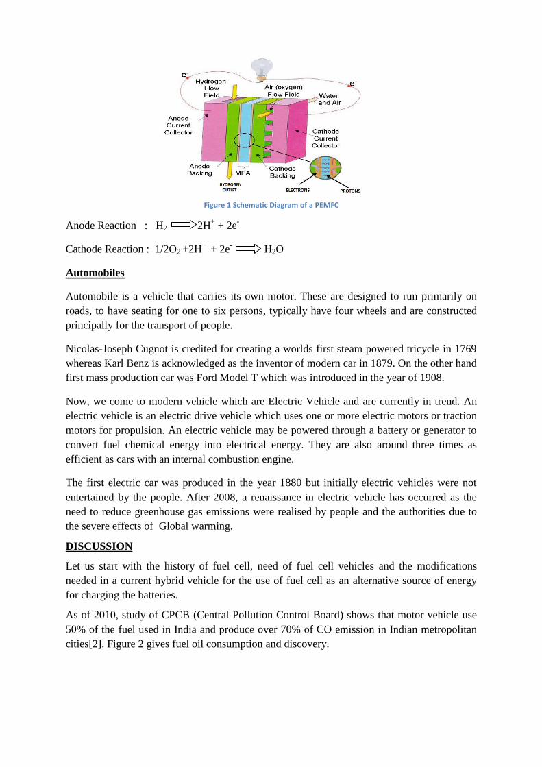
Figure 1 Schematic Diagram of a PEMFC
Anode Reaction : H2 2H+ + 2e
-
Cathode Reaction : 1/2O2 +2H+
+ 2e- H2O
Automobiles
Automobile is a vehicle that carries its own motor. These are designed to run primarily on
roads, to have seating for one to six persons, typically have four wheels and are constructed
principally for the transport of people.
Nicolas-Joseph Cugnot is credited for creating a worlds first steam powered tricycle in 1769
whereas Karl Benz is acknowledged as the inventor of modern car in 1879. On the other hand
first mass production car was Ford Model T which was introduced in the year of 1908.
Now, we come to modern vehicle which are Electric Vehicle and are currently in trend. An
electric vehicle is an electric drive vehicle which uses one or more electric motors or traction
motors for propulsion. An electric vehicle may be powered through a battery or generator to
convert fuel chemical energy into electrical energy. They are also around three times as
efficient as cars with an internal combustion engine.
The first electric car was produced in the year 1880 but initially electric vehicles were not
entertained by the people. After 2008, a renaissance in electric vehicle has occurred as the
need to reduce greenhouse gas emissions were realised by people and the authorities due to
the severe effects of Global warming.
DISCUSSION
Let us start with the history of fuel cell, need of fuel cell vehicles and the modifications
needed in a current hybrid vehicle for the use of fuel cell as an alternative source of energy
for charging the batteries.
As of 2010, study of CPCB (Central Pollution Control Board) shows that motor vehicle use
50% of the fuel used in India and produce over 70% of CO emission in Indian metropolitan
cities[2]. Figure 2 gives fuel oil consumption and discovery.
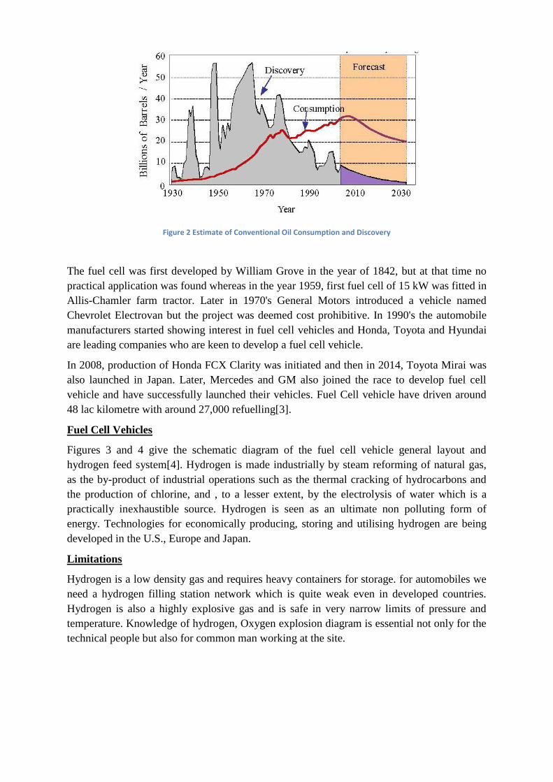
Figure 2 Estimate of Conventional Oil Consumption and Discovery
The fuel cell was first developed by William Grove in the year of 1842, but at that time no
practical application was found whereas in the year 1959, first fuel cell of 15 kW was fitted in
Allis-Chamler farm tractor. Later in 1970's General Motors introduced a vehicle named
Chevrolet Electrovan but the project was deemed cost prohibitive. In 1990's the automobile
manufacturers started showing interest in fuel cell vehicles and Honda, Toyota and Hyundai
are leading companies who are keen to develop a fuel cell vehicle.
In 2008, production of Honda FCX Clarity was initiated and then in 2014, Toyota Mirai was
also launched in Japan. Later, Mercedes and GM also joined the race to develop fuel cell
vehicle and have successfully launched their vehicles. Fuel Cell vehicle have driven around
48 lac kilometre with around 27,000 refuelling[3].
Fuel Cell Vehicles
Figures 3 and 4 give the schematic diagram of the fuel cell vehicle general layout and
hydrogen feed system[4]. Hydrogen is made industrially by steam reforming of natural gas,
as the by-product of industrial operations such as the thermal cracking of hydrocarbons and
the production of chlorine, and , to a lesser extent, by the electrolysis of water which is a
practically inexhaustible source. Hydrogen is seen as an ultimate non polluting form of
energy. Technologies for economically producing, storing and utilising hydrogen are being
developed in the U.S., Europe and Japan.
Limitations
Hydrogen is a low density gas and requires heavy containers for storage. for automobiles we
need a hydrogen filling station network which is quite weak even in developed countries.
Hydrogen is also a highly explosive gas and is safe in very narrow limits of pressure and
temperature. Knowledge of hydrogen, Oxygen explosion diagram is essential not only for the
technical people but also for common man working at the site.
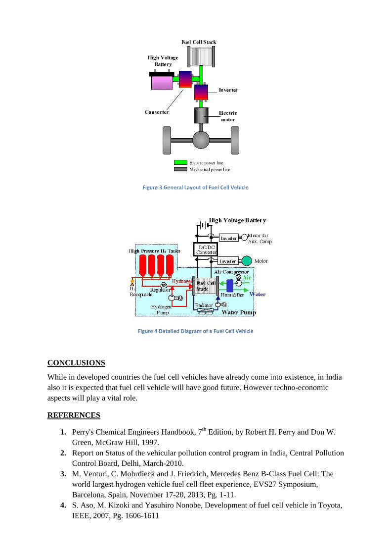
Figure 3 General Layout of Fuel Cell Vehicle
Figure 4 Detailed Diagram of a Fuel Cell Vehicle
CONCLUSIONS
While in developed countries the fuel cell vehicles have already come into existence, in India
also it is expected that fuel cell vehicle will have good future. However techno-economic
aspects will play a vital role.
REFERENCES
1. Perry's Chemical Engineers Handbook, 7th
Edition, by Robert H. Perry and Don W.
Green, McGraw Hill, 1997.
2. Report on Status of the vehicular pollution control program in India, Central Pollution
Control Board, Delhi, March-2010.
3. M. Venturi, C. Mohrdieck and J. Friedrich, Mercedes Benz B-Class Fuel Cell: The
world largest hydrogen vehicle fuel cell fleet experience, EVS27 Symposium,
Barcelona, Spain, November 17-20, 2013, Pg. 1-11.
4. S. Aso, M. Kizoki and Yasuhiro Nonobe, Development of fuel cell vehicle in Toyota,
IEEE, 2007, Pg. 1606-1611