study, design, analysis & development of barrier with
TRANSCRIPT
International Journal of Thesis Projects and Dissertations (IJTPD) Vol. 7, Issue 4, pp: (1-24), Month: October - December 2019, Available at: www.researchpublish.com
Page | 1 Research Publish Journals
Study, Design, Analysis & Development of
Barrier with Enhanced Mechanical &
Electrical Properties through Hybrid Materials 1Mr. P Jagdishwar,
2Dr Prabhash Jain
1Dy MGR (DESIGN), Switchgear Division, BHEL, Bhopal
2HOD, Depart of Mechanical Engineering, Barkatullah University, Bhopal
Abstract: In Gas Insulated Switchgear (GIS) of BHEL make, the Dielectric clearance of phase to earth is
maintained by filling SF6 Gas at rated pressure between the Enclosure & the HV components. In order to
maintain the position of all HV components for proper dielectric clearances Barriers are used. These barriers not
only provides the support but also maintains dielectric zone but also leads to provide the cushioning affect during
the assembly of various modules. Purpose of an insulator is to prevent the unwanted flow of current from the
energized conductor or conducting parts. Electrical insulation plays a vital role in every electrical system as it is
concerned with the safety of Human. An electrical insulator provides very high resistance so that practically no
current can flow through it. The objective of this thesis is to analyses the behavior of barrier manufactured
through hybrid material. Finite element analysis method is used to carry out the research work to validate the
mechanical strength. To perform finite element analysis, ANSYS Mechanical is used. Failure criteria adopted is
Maximum Stress theory. First, results of this work are validated through FEM and then final prototypes will be
manufactured to evaluate the electric behavior of the new Barrier.
Keywords: Hybrid, Epoxy-resin, Nylon, Insulating, Gas Insulated Switchgear, Barrier, Megger, ANSYS, FEM.
I. INTRODUCTION
GIS or Gas Insulated Switchgear
Air insulated power transmission and distribution substations suffer variation in the dielectric withstand capability of air
with varying ambient conditions and deterioration of the exposed components due to oxidising and corrosive nature of the
environment. The size of the substation is also substantial due to poor dielectric strength of air. In order to enhance the life
and reliability of a power transmission and distribution substation, it is desirable to protect the substation components
from corrosive and oxidising environment. Metal encapsulation of the substation elements provides a simple and effective
solution to the durability issue of the substations. Bus duct, with pressurised nitrogen gas, is a good example of devices
with metal encapsulation used in power substations. The size of the container is a direct function of the dielectric strength
of the insulating medium. The container/enclosure sizes are, thus, large with a poor insulation, like air or nitrogen. Use of
higher dielectric strength gaseous medium, like sulphur hexa-fluoride (SF6), instead of air, helps in manifold reduction in
the size of the substation component. The grounded metal encapsulation, on the other hand, makes the equipment safe,
from safety point of view, as the live components are no more within the reach of the operator. The electric field intensity,
at the enclosure surface, is reduced to zero as the enclosure is solidly grounded. Using this design philosophy,
substation/switchyard equipment, like, circuit breaker, disconnector, earth switch, bus bar, instrument transformers (both
current and voltage), have been metal encapsulated or metal-enclosed and pressurised with SF6 since the year 1968
commercially. The assembly of such equipment at a substation is defined as Gas Insulated and Metal Enclosed System
(GIMES) by International Electro-technical Commission (IEC). The equipment is popularly known as Gas Insulated
Substation (GIS) system. The term “GIS” is also used sometimes to refer to Gas Insulated Switchgear.
The medium voltage GIS equipment features vacuum as the interrupting medium and SF6 gas as the main insulation.
Designs using SF6 medium for both insulation and interruption are also available. Two operating pressures are specified
for such equipment (one for insulation and the other for interruption). The high and extra-high voltage GIS are,
essentially, two pressure systems for non-availability of vacuum interrupters in high and extra-high voltage classes.
International Journal of Thesis Projects and Dissertations (IJTPD) Vol. 7, Issue 4, pp: (1-24), Month: October - December 2019, Available at: www.researchpublish.com
Page | 2 Research Publish Journals
Metal encapsulation and SF6 gas insulation of the live high voltage substation components in a GIS result in reduced
space requirement, to one-sixth (~15%), as compared to a conventional air insulated yard substation. The size is reduced
to about 8% for higher kV class GIS [1]
In modern-days electrical installations which call for maintenance -free equipment, Vacuum Circuit Breakers (VCBs) and
SF6 circuit breakers are being increasingly used VCBs for their minimal maintenance requirements with respect to the
switching functions performed and SF6 circuit breakers on account of their immunity to the climatic and environmental
conditions. Both of these advantageous features , in addition to compactness, can now be provided in a new generation of
compact SF6 gas insulated switchgear based on a hybrid of VCB and SF6 circuit breaker technologies. Such switchgear,
using well-proven vacuum interrupter and SF6 gas insulation, are manufacturing by BHEL for medium voltage
application at 36KV and 11kV having panels of modular design and entailing minimum bay width resulting in efficient
utilization of space [2]. The same has been successfully tested and certified as per latest IEC.
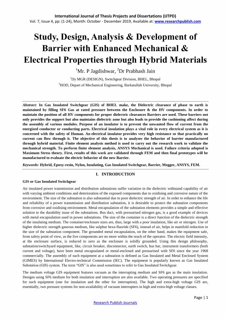
Gas-insulated high-voltage switchgear (GIS) is a compact metal encapsulated switchgear consisting of high-voltage
components such as circuit breakers and disconnectors, which can safely operate in confined spaces. GIS is used where
space is limited, for example, extensions, in city buildings, on roofs, on offshore platforms, industrial plants and hydro
power plants. BHEL provides a complete range of products for all ratings and applications from 36 kV to 420 kV
matching current and future requirements for modern switchgears.
Applications
Power Generation &Transmission
Refinery Industries
Steel Plant
Railway
Integration of renewable power generation units to the grid
Figure 1: GIS product range of M/s BHEL make
[Courtesy: Bhel Bhopal]
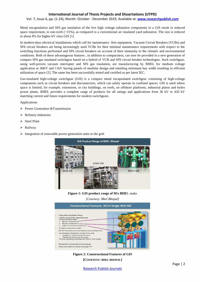
Figure 2: Constructional Features of GIS
[COURTESY: BHEL BHOPAL]

International Journal of Thesis Projects and Dissertations (IJTPD) Vol. 7, Issue 4, pp: (1-24), Month: October - December 2019, Available at: www.researchpublish.com
Page | 3 Research Publish Journals
Following are the principle gas insulated modules for a substation:
1. Bus bar cum Disconnector or Isolator,
2. Circuit breaker,
3. Cable Compartment
The auxiliary gas insulated module or accessories, excluding control panel, required to complete a substation are:
1. Terminations,
2. Instrument voltage transformer, and
3. Surge and lighting arrester.
In GIS, all the equipment‟s of the electrical switchgear are enclosed by gas tight metal enclosure and SF6 gas is used as
insulation between live parts of the equipment‟s and earthed metal enclosure. This type of switchgear is available from 36
KV systems to 420 KV system. For establishing electrical substation in very limited place this type of SF6 insulated
electrical switchgear plays the major role [3]
Figure 3: M/s BHEL make GIS
[COURTESY: BHEL BHOPAL]
There are different Types of gas insulated metal enclosed switchgears available depending upon their constructional
feature.
Isolated Phase GIS
In this configuration, each phase of the bay is assembled separately. That is, for each phase, one pole of circuit breaker, a
single pole of electrical isolator, one phase assembly of current transformer are assembled together. This type of GIS
requires larger bay width as compared to other gas insulated switchgear system.
Integrated 3 Phase GIS
In this configuration all three phase of circuit breaker, 3 phases of disconnectors and three phase current transformer are
encapsulated in an individual metal enclosure. The arrangement forms a three-phase module for the element. The size of
this type of module is one third of the isolated phase GIS.
Hybrid GIS System
It is a suitable combination of isolated phase and three phase common elements. Here three phase common bus bar system
simplifies the connection from the bus bar. The isolated phase equipment prevents phase to phase faults. This is an
optimum design considering, both facts in mind, i.e. space requirement and maintenance facility.
BARRIER
BUS
ENCLOSURE
SWITCH/
BREAKER
ENCLOSURE
International Journal of Thesis Projects and Dissertations (IJTPD) Vol. 7, Issue 4, pp: (1-24), Month: October - December 2019, Available at: www.researchpublish.com
Page | 4 Research Publish Journals
Compact GIS
In this GIS or gas insulated switchgear system than one functional element are encapsulate in a single metal enclosure.
For example, in some design, a three phase circuit breaker, current transformer, earth switches, even other feeder elements
are covered together in a single metal capsule.
Highly Integrated System
This design was introduced in the year of 2000, where, total substation equipment‟s are encapsulated together in single
enclosure housing. This single unit gas insulated substation has gained user appreciation as it is a complete solution for an
outdoor substation, in a single unit. As such, only equipment (HIS) is substitute of a total outdoor switch yard.
1.2 Dielectric withstand test
A dielectric withstand test or high potential or Hipot test is an electrical test performed on a component or product to
determine the effectiveness of its insulation. The test may be between mutually insulated sections of a part or energized
parts and electrical ground. The test is a means to qualify a device's ability to operate safely during rated electrical
conditions [4]. If the current through a device under test is less than a specified limit at the required test potential and time
duration, the device meets the dielectric withstand requirement. A dielectric withstand test may be done as a factory test
on new equipment, or may be done on apparatus already in service as a routine maintenance test [5].
For switchgears, typical Hipot equipment leakage current trip is within 1A. and are set by the user according to test object
characteristics and rate of voltage application. The objective is to choose a current setting that will not cause the tester to
falsely trip during voltage application, while at the same time, selecting a value that minimizes possible damage to the
device under test should an inadvertent discharge or breakdown occur [6].
1.3 Megger Test
Insulation resistance quality of an electrical system degrades with time, environment condition i.e. temperature, humidity,
moisture and dust particles. It also get impacted negatively due to the presence of electrical and mechanical stress, so it‟s
become very necessary to check the IR (Insulation resistance) of equipment at a constant regular interval to avoid any
measure fatal or electrical shock.
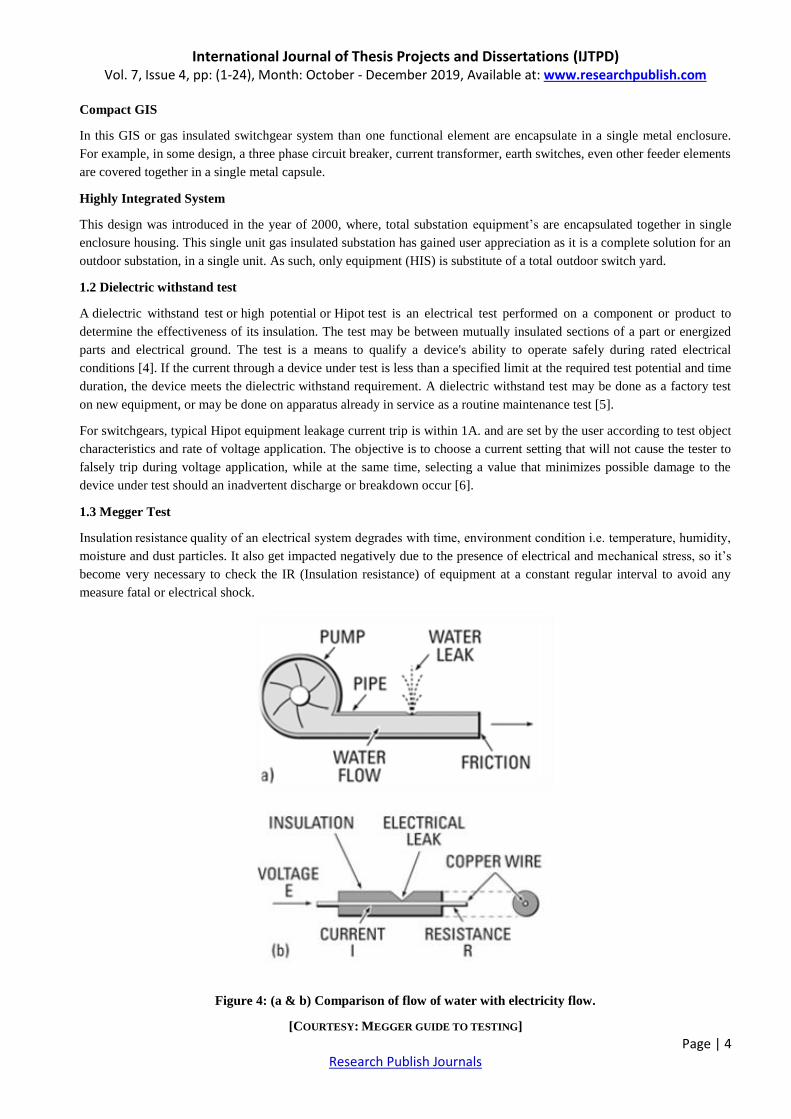
Figure 4: (a & b) Comparison of flow of water with electricity flow.
[COURTESY: MEGGER GUIDE TO TESTING]

International Journal of Thesis Projects and Dissertations (IJTPD) Vol. 7, Issue 4, pp: (1-24), Month: October - December 2019, Available at: www.researchpublish.com
Page | 5 Research Publish Journals
To understand insulation testing you really do not need to go into the mathematics of electricity, but one simple equation
– Ohm‟s law – can be very helpful in appreciating many aspects. Even if you‟ve been exposed to this law before, it may
be a good idea to review it in the light of insulation testing. The purpose of insulation around a conductor is much like that
of a pipe carrying water, and Ohm‟s law of electricity can be more easily understood by a comparison with water flow. In
Fig. 4 we show this comparison. Pressure on water from a pump causes flow along the pipe (Fig. 4a). If the pipe were to
spring a leak, you would waste water and lose some water pressure. With electricity, voltage is like the pump pressure,
causing electricity to flow along the copper wire (Fig. 4b). As in a water pipe, there is some resistance to flow, but it is
much less along the wire than it is through the insulation [7].
Megger testing does not cause any damage, making it a good option when someone does not want to put holes in walls to
test electrical insulation for any problems or issues. The testing device only goes between 500 and 1,000 volts, which is
relatively low. Due to the low voltage, some punctures in insulation go undetected. It generally provides information
about the leakage current and whether insulation areas have excessive dirt or moisture as well as the amount of moisture,
deterioration and winding faults.
1.4 Principle of insulation testing and influencing factors
The Megger insulation tester is a small, portable instrument that gives you a direct reading of insulation resistance in
ohms or mega-ohms. For good insulation, the resistance usually reads in the mega-ohm range. The Megger insulation
tester is essentially a high-range resistance meter (ohm-meter) with a built-in direct-current generator. This method is non-
destructive that is, it does not cause deterioration of the insulation.
Figure 5: Typical Megger test instrument hook-up to measure insulation resistance
[COURTESY: MEGGER GUIDE TO TESTING]
Figure 6: Typical Megger test instrument hook-up to measure insulation resistance
[COURTESY: MEGGER GUIDE TO TESTING]
Insulation resistance measurement is based on Ohm's Law. By injecting a known DC voltage lower than the voltage for
dielectric testing and then measuring the current flowing, it is very simple to determine the value of the resistance. In
principle, the value of the insulation resistance is very high but not infinite, so by measuring the low current flowing, the
International Journal of Thesis Projects and Dissertations (IJTPD) Vol. 7, Issue 4, pp: (1-24), Month: October - December 2019, Available at: www.researchpublish.com
Page | 6 Research Publish Journals
mega-ohmmeter indicates the insulation resistance value, providing a result in kW, MW, GW and also TW (on some
models). This resistance characterizes the quality of the insulation between two conductors and gives a good indication of
the risks of leakage currents flowing. A number of factors affect the value of the insulation resistance and therefore the
value of the current flowing when a constant voltage is applied to the circuit being tested. These factors, such as
temperature or humidity for example, may significantly affect the measurement result. First let's analyse the nature of the
currents flowing during an insulation measurement, using the hypothesis that these factors do not influence the
measurement.
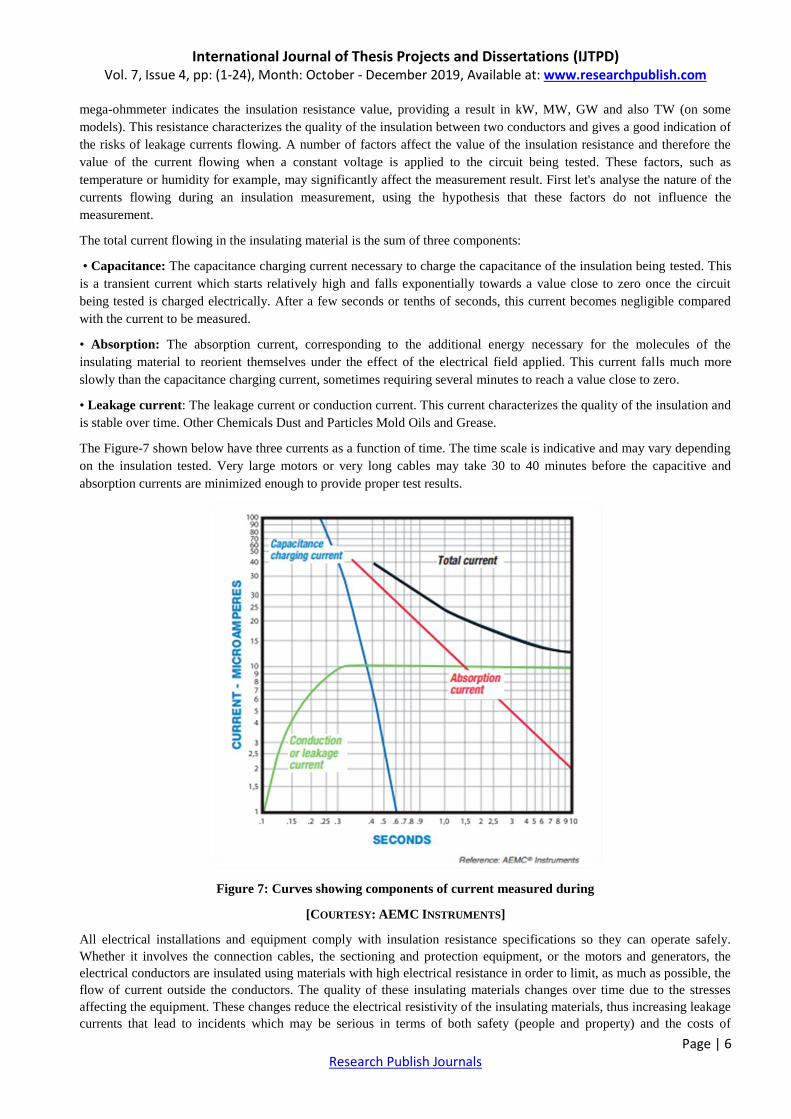
The total current flowing in the insulating material is the sum of three components:
• Capacitance: The capacitance charging current necessary to charge the capacitance of the insulation being tested. This
is a transient current which starts relatively high and falls exponentially towards a value close to zero once the circuit
being tested is charged electrically. After a few seconds or tenths of seconds, this current becomes negligible compared
with the current to be measured.
• Absorption: The absorption current, corresponding to the additional energy necessary for the molecules of the
insulating material to reorient themselves under the effect of the electrical field applied. This current falls much more
slowly than the capacitance charging current, sometimes requiring several minutes to reach a value close to zero.
• Leakage current: The leakage current or conduction current. This current characterizes the quality of the insulation and
is stable over time. Other Chemicals Dust and Particles Mold Oils and Grease.
The Figure-7 shown below have three currents as a function of time. The time scale is indicative and may vary depending
on the insulation tested. Very large motors or very long cables may take 30 to 40 minutes before the capacitive and
absorption currents are minimized enough to provide proper test results.
Figure 7: Curves showing components of current measured during
[COURTESY: AEMC INSTRUMENTS]
All electrical installations and equipment comply with insulation resistance specifications so they can operate safely.
Whether it involves the connection cables, the sectioning and protection equipment, or the motors and generators, the
electrical conductors are insulated using materials with high electrical resistance in order to limit, as much as possible, the
flow of current outside the conductors. The quality of these insulating materials changes over time due to the stresses
affecting the equipment. These changes reduce the electrical resistivity of the insulating materials, thus increasing leakage
currents that lead to incidents which may be serious in terms of both safety (people and property) and the costs of
International Journal of Thesis Projects and Dissertations (IJTPD) Vol. 7, Issue 4, pp: (1-24), Month: October - December 2019, Available at: www.researchpublish.com
Page | 7 Research Publish Journals
production stoppages. In addition to the measurements carried out on new and reconditioned equipment during
commissioning, regular insulation testing on installations and equipment helps to avoid such incidents through preventive
maintenance. These tests detect aging and premature deterioration of the insulating properties before they reach a level
likely to cause the incidents described above. At this stage, it is a good idea to clarify the difference between two types of
measurements which are often confused: dielectric testing and insulation resistance measurement. Dielectric strength
testing, also called "breakdown testing", measures an insulation's ability to withstand a medium-duration voltage surge
without spark over occurring. In reality, this voltage surge may be due to lightning or the induction caused by a fault on a
power transmission line. The main purpose of this test is to ensure that the construction rules concerning leakage paths
and clearances have been followed. This test is often performed by applying an AC voltage but can also be done with a
DC voltage. This type of measurement requires a hipot tester. The result obtained is a voltage value usually expressed in
kilovolts (kV). Dielectric testing may be destructive in the event of a fault, depending on the test levels and the available
energy in the instrument. For this reason, it is reserved for type tests on new or reconditioned equipment. Insulation
resistance measurement, however, is non-destructive under normal test conditions. Carried out by applying a DC voltage
with a smaller amplitude than for dielectric testing, it yields a result expressed in kW, MW, GW or TW. This resistance
indicates the quality of the insulation between two conductors. Because it is non-destructive, it is particularly useful for
monitoring insulation aging during the operating life of electrical equipment or installations. This measurement is
performed using an insulation tester, also called a megohmmeter.
1.5 Insulation and causes of insulation failure
Because measuring insulation with a mega-ohmmeter is part of a wider preventive maintenance policy, it is important to
understand the different possible causes of insulation performance deterioration so that you can take steps to correct it. It
is possible to divide these causes of insulation failure into five groups, while keeping in mind, if no corrective measures
are implemented; these different causes are superimposed, leading to insulation breakdown and equipment failure [8]
Electrical stresses: Mainly linked to over voltages and under voltages.
Mechanical stresses: Frequent start-up and shutdown sequences can cause mechanical stresses. Also, balancing
problems on rotating machinery and any direct stress to the cables and the installations in general.
Chemical stresses: The proximity of chemicals, oils, corrosive vapours and dust, in general, affects the insulation
performance of the materials.
Stresses linked to temperature variations: When combined with the mechanical stresses caused by the start-up and
shutdown sequences, expansion and contraction stresses affect the properties of the insulating materials. Operation at
extreme temperatures also leads to aging of the materials.
Environmental contamination: The build-up of mold and particulate deposits in warm, moist environments also
contributes to the deterioration of installations' insulation properties.
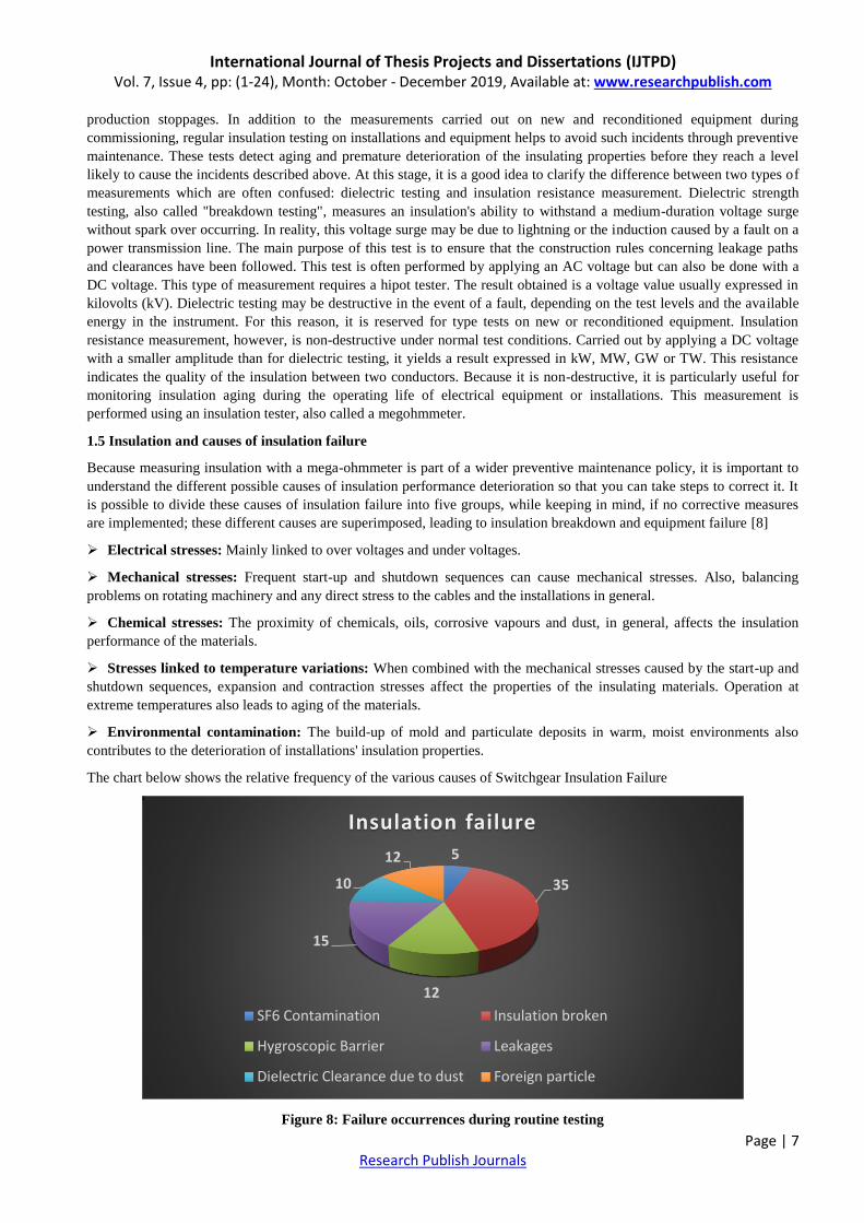
The chart below shows the relative frequency of the various causes of Switchgear Insulation Failure
Figure 8: Failure occurrences during routine testing
5
35
12
15
10
12
Insulation failure
SF6 Contamination Insulation broken
Hygroscopic Barrier Leakages
Dielectric Clearance due to dust Foreign particle
International Journal of Thesis Projects and Dissertations (IJTPD) Vol. 7, Issue 4, pp: (1-24), Month: October - December 2019, Available at: www.researchpublish.com
Page | 8 Research Publish Journals
1.6 Insulating / Dielectric materials
A dielectric material is a substance that is a poor conductor of electricity, but an efficient supporter of electrostatic field s.
If the flow of current between opposite electric charge poles is kept to a minimum while the electrostatic lines of flux are
not impeded or interrupted, an electrostatic field can store energy. This property is useful in capacitor s, especially at radio
frequencies. Dielectric materials are also used in the construction of radio-frequency transmission lines.
In practice, most dielectric materials are solid. Examples include porcelain (ceramic), mica, glass, plastics, and the oxides
of various metals. Some liquids and gases can serve as good dielectric materials. Dry air is an excellent dielectric, and is
used in variable capacitors and some types of transmission lines. Distilled water is a fair dielectric. A vacuum is an
exceptionally efficient dielectric.
An important property of a dielectric is its ability to support an electrostatic field while dissipating minimal energy in the
form of heat. The lower the dielectric loss (the proportion of energy lost as heat), the more effective is a dielectric
material. Another consideration is the dielectric constant , the extent to which a substance concentrates the electrostatic
lines of flux. Substances with a low dielectric constant include a perfect vacuum, dry air, and most pure, dry gases such as
helium and nitrogen. Materials with moderate dielectric constants include ceramics, distilled water, paper, mica,
polyethylene, and glass. Metal oxides, in general, have high dielectric constants.
The prime asset of high-dielectric-constant substances, such as aluminium oxide, is the fact that they make possible the
manufacture of high-value capacitors with small physical volume. However, these materials are generally not able to
withstand electrostatic fields as intense as low-dielectric-constant substances such as air. If the voltage across a dielectric
material becomes too great -- that is, if the electrostatic field becomes too intense -- the material will suddenly begin to
conduct current. This phenomenon is called dielectric breakdown. In components that use gases or liquids as the dielectric
medium, this condition reverses itself if the voltage decreases below the critical point. But in components containing solid
dielectrics, dielectric breakdown usually results in permanent damage [9].
The word „Dielectric‟ comes from the Greek prefix „di‟ or „dia‟ meaning „across‟. Dielectric materials are plain and
simple electrical insulators. By the peripheral application of electrical field, these electrical insulators are polarised.
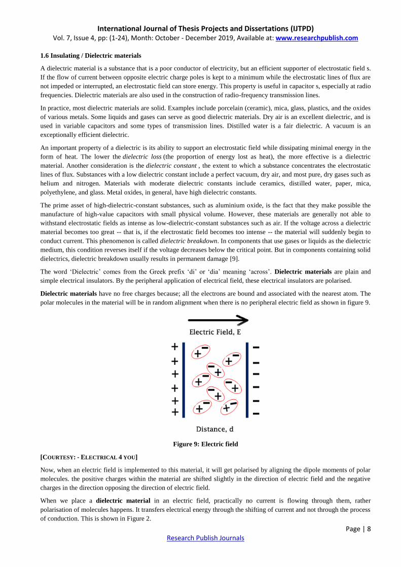
Dielectric materials have no free charges because; all the electrons are bound and associated with the nearest atom. The
polar molecules in the material will be in random alignment when there is no peripheral electric field as shown in figure 9.
Figure 9: Electric field
[COURTESY: - ELECTRICAL 4 YOU]
Now, when an electric field is implemented to this material, it will get polarised by aligning the dipole moments of polar
molecules. the positive charges within the material are shifted slightly in the direction of electric field and the negative
charges in the direction opposing the direction of electric field.
When we place a dielectric material in an electric field, practically no current is flowing through them, rather
polarisation of molecules happens. It transfers electrical energy through the shifting of current and not through the process
of conduction. This is shown in Figure 2.

International Journal of Thesis Projects and Dissertations (IJTPD) Vol. 7, Issue 4, pp: (1-24), Month: October - December 2019, Available at: www.researchpublish.com
Page | 9 Research Publish Journals
The dielectric material which is used in capacitors fulfils the following functions.
Decreases the useful electric field between the capacitor plates.
Boosts the capacitance of the capacitor plate structure.
Keep the conducting plates from coming in contact.
Reduce the possibility of shorting out by sparking during high voltages.
1.6.1 Types of Dielectric Materials
Vacuum, Solids, Liquids and Gases can be a dielectric material. Some of the examples of solid dielectric materials are
ceramics, paper, mica, glass etc. Liquid dielectric materials are distilled water, transformer oil etc. Gas dielectrics are
nitrogen, dry air, helium, oxides of various metals etc. Perfect vacuum is also a dielectric.
Table 1: List of Common Dielectric Materials
[COURTESY: - ELECTRICAL 4 YOU]
1.6.2 Application of Dielectric Materials
Dielectric materials can be used in capacitors for energy storage. It is used in photosensitive materials for charge storage
in laser printers and copying machines. It is used for mechanical actuation, sound generation, piezoelectricity, cap sense
etc.
Hybrid composite materials are increasingly utilized in many engineering applications because they offer a number of
enhanced properties and various advantages over traditional composite materials. The mechanical properties of hybrid
composites consist of n (n > 2) jointly working phases, which are very important. For this reason, the modeling of the
mechanical properties of hybrid composites as mentioned previously is done by using a linear coupling of numerical
simulation models. However, the mechanical behavior of hybrid composites depends not only on the character of a matrix
and reinforcements but also on properties of the interface between these components and the matrix, which must be taken
into consideration in the numerical modeling of the mechanical properties. Furthermore, the effect of environmental aging
should be taken into account for numerical modeling of hybrid composite materials [10].
2. LITERATURE REVIEW
The purpose of this literature review is to provide background information on the issues to be considered in this thesis and
to emphasize the relevance of the present study. This treatise embraces various aspects of use of Insulating items with a
special reference to their mechanical strength and dielectric characteristics. It includes reviews of available research
reports.
International Journal of Thesis Projects and Dissertations (IJTPD) Vol. 7, Issue 4, pp: (1-24), Month: October - December 2019, Available at: www.researchpublish.com
Page | 10 Research Publish Journals
Research work
Following researches reviewed on past works conducted for
R K Bharadwaj [11]- Macromolecules, 2001 - ACS Publications worked on Modelling the barrier properties of polymer-
layered silicate nanocomposites [ ]. In this Research conducted on the composite material made up of Organic and
Inorganic layered barrier properties. The application of this work relates to the insulating barrier shields. In this research
activity a simple model is developed to describe the permeability in filled polymers
1)
M Talaat, MA Farahat, T Said [12] - Journal of Physics and Chemistry of Solids, 2018 – Elsevier et al. worked
onNumerical investigation of the optimal characteristics of a transverse layer of dielectric barrier in a non-uniform electric
field. It studies the numerical model effect of the transverse layer of DB located at non-uniform electric field is present. A
simulation model using FEM has been used to investigate the accuracy of the proposed equation. The effects of varying
the barrier position, thickness, and its permittivity on the maximum values of the electric field are investigated.
2)
Mohammad Jawaid Mohamed Thariq Naheed Saba [13] -Modelling of Damage Processes in Bio composites, Fibre-
Reinforced Composites and Hybrid Composites, 2019 worked on Numerical modelling of hybrid composite materials. In
this research, study of hybrid composite materials was carried & its utilization in many engineering applications because
they offer a number of enhanced properties and various advantages over traditional composite materials. For this reason,
the modelling of the mechanical properties of hybrid composites is done by using a linear coupling of numerical
simulation models. However, the mechanical behaviour of hybrid composites depends not only on the character of a
matrix and reinforcements but also on properties of the interface between these components and the matrix, which must
be taken into consideration in the numerical modeling of the mechanical properties. Furthermore, the effect of
environmental aging should be taken into account for numerical modeling of hybrid composite materials.
A. Karakoti, M. Manikandan [14], et al. Worked on Finite element modelling of natural fibre-based hybrid composites.
In this research, natural fibres and their classifications are discussed, followed by the hybrid composite and its material
modelling. Continuous, numerical solutions of natural fiber-based hybrid composites are also demonstrated through
appropriate finite element steps. For computational purposes, two different natural fibers, i.e., jute and flax, and epoxy as
matrix material are used to different extents. The overall material properties of hybrid composites are evaluated through a
simple rule of hybrid mixture and the modified Halpin–Tsai scheme. A higher-order mathematical model is developed in
a finite element framework to obtain the flexural responses of hybrid composites. The desired responses of hybrid
composites are obtained through customized MATLAB code. Influences of different parameters such as geometrical
(side-to-thickness ratio, side-to-length ratio), volume fractions, number of layers, and support conditions on the flexural
responses of a natural fiber-based hybrid composite panel are exemplified and discussed in detail through appropriate
illustrations. It is found that fully clamped and large side-to-length ratio composite panels exhibit minimum deflection
under uniform pressure. However, the addition of flax content enhances the overall stiffness and strength of a hybrid
composite.
Knowledge Gap in Earlier Investigations
In spite of a number of research works reported in the past, there is a huge knowledge gap that demands a well-planned
and systematic research in this area of Hybrid materials. An exhaustive review of the published literature reveals that:
Most of the investigations are aimed at enhancing the thermal conductivity of the polymer by adding conductive fillers
rather than attempting to improve its insulation capability.
Most of the studies are for single filler composites and only very few papers have reported on the synergistic effects of
two different kinds of fillers on the thermal/dielectric properties.
Reports are available in the literature on studies carried out on mechanical, thermal and electrical behaviour of Epoxy
filled resin /& Nylon, but surprisingly, there is no report available on Hybrid materials in parallel system.
Some investigators have developed numerical and analytical models for estimation of effective thermal conductivity
of particulate filled composites but there is no model available for composites filled with hybrid i.e. more than one type of
fillers.
International Journal of Thesis Projects and Dissertations (IJTPD) Vol. 7, Issue 4, pp: (1-24), Month: October - December 2019, Available at: www.researchpublish.com
Page | 11 Research Publish Journals
In view of the above, the present work is undertaken to investigate on the composite behaviour of Epoxy-resin & Nylon
based materials.
Scope of the Present Work
The scope of this work are outlined as follows:
• Development of theoretical model in 3D platform for Hybrid barrier
• Structural load analysis in ANSYS for validating the design requirements using finite element method (FEM).
• Manufacturing of prototype & assembly for testing and validation of conceptual model.
• Study of the effects of Hybrid barrier properties like Insulation resistance, & High Voltage behaviour for the
composites.
The present work involves the study of materials used for the new hybrid Barrier. Here we used both Epoxy-resin &
Nylon material for its manufacturing. Their properties are detailed below:
Epoxy resins [15]
The Epoxy-resins based materials have highest performance from those available in this period. The term „epoxy‟ refers
to a chemical group consisting of an oxygen atom bonded with two carbon atoms. The simplest epoxy is a 3-member ring
structure known by the term „alpha-epoxy‟ or „1,2-epoxy‟.
Usually specifiable by their characteristic amber or brown coloring, epoxy resins have variety of helpful properties. Both
the liquid resin and the curing agents forms low viscosity easily with processed systems. These are easily and quickly
cured at any temperature from 5°C to 150°C, depending on the choice of curing agent. One of the most advantageous
properties of epoxies is their low shrinkage during cure which minimizes fabric „print-through‟ and internal stresses. High
adhesive strength and high mechanical properties are enhanced by high electrical insulation and good chemical resistance.
Epoxies realize uses as adhesives, caulking compounds, casting compounds, sealants, varnishes and paints, also as
laminating resins for a spread of commercial applications.
Epoxy resins are formed from a long chain molecular structure similar to vinyl ester with reactive sites at either end. In
the epoxy resin, however, these reactive sites are formed by epoxy groups instead of ester groups. The absence of ester
groups means that the epoxy resin has particularly good water resistance. The epoxy molecule also contains two ring
groups at its center which are able to absorb both mechanical and thermal stresses better than linear groups and therefore
they are very good in stiffness, toughness and heat resistant properties.
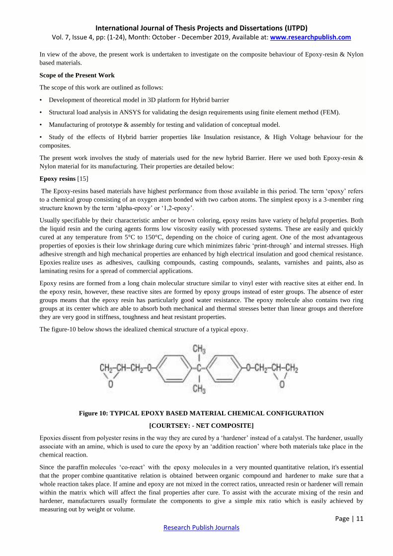
The figure-10 below shows the idealized chemical structure of a typical epoxy.
Figure 10: TYPICAL EPOXY BASED MATERIAL CHEMICAL CONFIGURATION
[COURTSEY: - NET COMPOSITE]
Epoxies dissent from polyester resins in the way they are cured by a „hardener‟ instead of a catalyst. The hardener, usually
associate with an amine, which is used to cure the epoxy by an „addition reaction‟ where both materials take place in the
chemical reaction.
Since the paraffin molecules „co-react‟ with the epoxy molecules in a very mounted quantitative relation, it's essential
that the proper combine quantitative relation is obtained between organic compound and hardener to make sure that a
whole reaction takes place. If amine and epoxy are not mixed in the correct ratios, unreacted resin or hardener will remain
within the matrix which will affect the final properties after cure. To assist with the accurate mixing of the resin and
hardener, manufacturers usually formulate the components to give a simple mix ratio which is easily achieved by
measuring out by weight or volume.
International Journal of Thesis Projects and Dissertations (IJTPD) Vol. 7, Issue 4, pp: (1-24), Month: October - December 2019, Available at: www.researchpublish.com
Page | 12 Research Publish Journals
Epoxy resins are characterized by their
Very good electrical properties and chemical resistance,
Good strength and low absorption of moisture.
Versatile resins, offering particularly excellent resistance to corrosion (solvents, alkalis and some acids),
High strength/weight ratio,
Dimensional stability and Adhesion properties.
The resins are relatively high in viscosity, so that they are usually moulded at temperatures in the region of 50-100°C, or
dissolved in an inert solvent to reduce viscosity to a point at which lamination at room temperature becomes possible.
Curing agents, also referred to as catalysts, hardeners or accelerators, are used, either acting by catalytic action or directly
reacting with the resin.
With correct additives, epoxy resins can exhibit outstanding resistance to heat (some up to 290°C) and electrical
insulation properties. They can be either liquid or solid form and can be formulated to cure either at room temperature of
with the aid of heat.
In order to obtain high performance heat curing is done. Epoxies generally cure more slowly than other thermoset resins.
Cold-cure types are available, but performance is usually better when cured at 40-60°C.
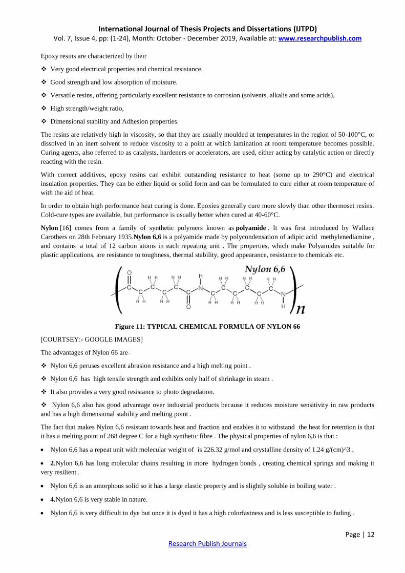
Nylon [16] comes from a family of synthetic polymers known as polyamide . It was first introduced by Wallace
Carothers on 28th February 1935.Nylon 6,6 is a polyamide made by polycondensation of adipic acid methylenediamine ,
and contains a total of 12 carbon atoms in each repeating unit . The properties, which make Polyamides suitable for
plastic applications, are resistance to toughness, thermal stability, good appearance, resistance to chemicals etc.
Figure 11: TYPICAL CHEMICAL FORMULA OF NYLON 66
[COURTSEY:- GOOGLE IMAGES]
The advantages of Nylon 66 are-
Nylon 6,6 peruses excellent abrasion resistance and a high melting point .
Nylon 6,6 has high tensile strength and exhibits only half of shrinkage in steam .
It also provides a very good resistance to photo degradation.
Nylon 6,6 also has good advantage over industrial products because it reduces moisture sensitivity in raw products
and has a high dimensional stability and melting point .
The fact that makes Nylon 6,6 resistant towards heat and fraction and enables it to withstand the heat for retention is that
it has a melting point of 268 degree C for a high synthetic fibre . The physical properties of nylon 6,6 is that :
Nylon 6,6 has a repeat unit with molecular weight of is 226.32 g/mol and crystalline density of 1.24 g/(cm)^3 .
2.Nylon 6,6 has long molecular chains resulting in more hydrogen bonds , creating chemical springs and making it
very resilient .
Nylon 6,6 is an amorphous solid so it has a large elastic property and is slightly soluble in boiling water .
4.Nylon 6,6 is very stable in nature.
Nylon 6,6 is very difficult to dye but once it is dyed it has a high colorfastness and is less susceptible to fading .

International Journal of Thesis Projects and Dissertations (IJTPD) Vol. 7, Issue 4, pp: (1-24), Month: October - December 2019, Available at: www.researchpublish.com
Page | 13 Research Publish Journals
Its chemical properties does not allow it to be affected by solvents such as water , alcohol etc .
The applications of Nylon 6,6 is :
Because Nylon is a light material, it is used in parachutes.
Nylon 6,6 is waterproof in nature so it is also used to make swimwear.
Nylon 6,6 having a high melting point make it more resistant to heat and friction so it is suitable to be used in in
airports , offices and other places which are more liable to wear and tear .
Nylon 6,6 being waterproof in nature is used to make machine parts. It is also used in the following like airbags,
carpets, ropes. Hoses etc . Hence Nylon 66 is a very useful creation by mankind.
3. OBJECTIVE & PROBLEM FORMULATION
3.1 OBJECTIVE OF THE WORK
The objective of this work is to Design & develop a prototype of Hybrid barrier to perform the Megger test. It involves
development of barrier which is suitable not only for support but also provide the requisite insulation of phase to earth.
For this work, a 3D model is prepared in UGNX platform & then subjected to loadings as per boundary conditions in
ANSYS software for structural analysis.
The variables considered are
Material
Epoxy-resin (Inner ring)
Nylon-6 (Outer ring)
Loading
Axial compressive load at hardware mounting locations
Boundary Conditions
Fixed support at inner ring & Hardwares
The details of how the work has been propagated is described in the next chapter named as Methodology. Results
obtained by the simulations are presented in graphical and tabular form in the chapter 5 i.e. Results and Discussion.
3.2 PROBLEM DEFINITION
This work is identified based on the failure rate observed during the routine testing of MV GIS in BHEL (refer Figure-8).
It was found that 35% failure occurring due to insulation failure. When Epoxy-based barriers were used, the barriers
found getting cracked at hardware mounting locations under the bolt pressure. Later the barrier were modified with Nylon
material, which resolved the crack of the barrier. Generally, the Switchboard should have more than 1Gega-ohm
Insulation resistance but with Nylon based material low megger value was coming. This was occurring due to the
hygroscopic behaviour of Nylon.
4. METHODOLOGY
The aim of this thesis is to analyse the Structural load & Meggering behaviour of new Hybrid Barrier made from the
combination of Epoxy-resin & Nylon material with simulation for its pre-liminary design validation through various
software‟s like UGNX for modelling & ANSYS for structural load analysis. This work is further extended to manufacture
the prototype and conduct the meggering test to validate the design & study the improvements in properties of electrical
resistivity. This scope of work does not require performing the numerical analysis of above-mentioned problems as the
same is tested through prototype after validation of design through the ANSYS software [15].
Below figure-10 shows the 3D model created through NX-10 software for performing the design analysis.
International Journal of Thesis Projects and Dissertations (IJTPD) Vol. 7, Issue 4, pp: (1-24), Month: October - December 2019, Available at: www.researchpublish.com
Page | 14 Research Publish Journals
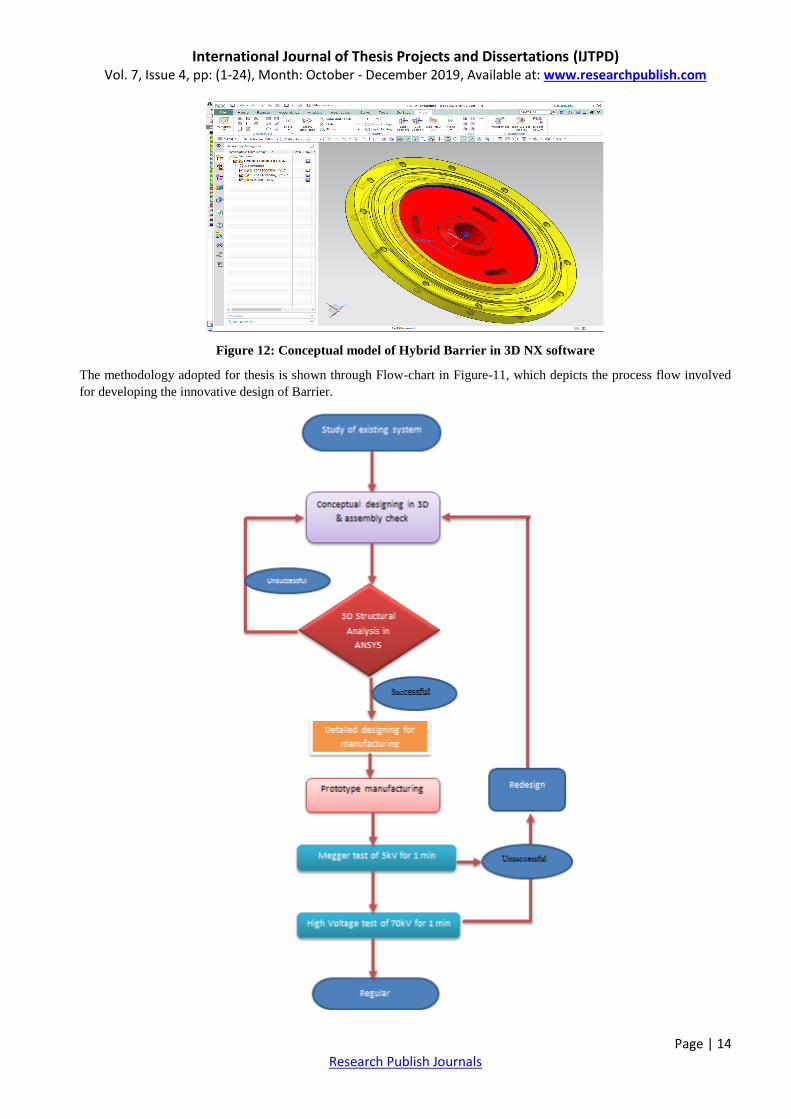
Figure 12: Conceptual model of Hybrid Barrier in 3D NX software
The methodology adopted for thesis is shown through Flow-chart in Figure-11, which depicts the process flow involved
for developing the innovative design of Barrier.

International Journal of Thesis Projects and Dissertations (IJTPD) Vol. 7, Issue 4, pp: (1-24), Month: October - December 2019, Available at: www.researchpublish.com
Page | 15 Research Publish Journals
Figure 13: Flowchart of methodology adopted
After the study of existing system, a conceptual designing was carried out for co-joining the two materials. The
conceptual 3D model was prepared in NX 10 & checked in the assembly through simulation. In order to evaluate the
mechanical failure, the component was subjected to loadings in structural analysis through ANSYS Workbench 18.1.
Following steps were used while processing the ANSYS analysis [16]:-
1. Pre-Processing step
Pre-processing which is normally called as Finite element modelling, which is the physical problem which is modelled to
Solve using Finite Element Method.
Pre Processing includes the following steps
Model Designing
Discretization or Meshing
Selection of elements
Geometrical properties
Material selection
Constrains or Boundary conditions
Loads
Type of analysis
Figure 14: Shows the Modelling of conceptual design of Hybrid barrier carried in NX-10 software along-with the
assigning material properties

International Journal of Thesis Projects and Dissertations (IJTPD) Vol. 7, Issue 4, pp: (1-24), Month: October - December 2019, Available at: www.researchpublish.com
Page | 16 Research Publish Journals
The designed conceptual model is then exported to ANSYS software for its structural evaluation. Initializing the ANSYS
space claim for its geometry validation in new platform as shown in figure-15
Figure 15: Shows the Modelled component imported in ANSYS Space claim for Geometry upload
After loading in ANSYS platform the component were assigned respective material, & assigned mesh size for fine quality
analysis. Mesh size of 5 mm used for load analysis as shown in figure-16 & 17.
Figure 16: Shows the initiation of Meshing process after assigning materials in ANSYS Workbench 18.1
International Journal of Thesis Projects and Dissertations (IJTPD) Vol. 7, Issue 4, pp: (1-24), Month: October - December 2019, Available at: www.researchpublish.com
Page | 17 Research Publish Journals
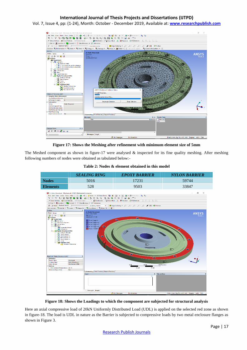
Figure 17: Shows the Meshing after refinement with minimum element size of 5mm
The Meshed component as shown in figure-17 were analysed & inspected for its fine quality meshing. After meshing
following numbers of nodes were obtained as tabulated below:-
Table 2: Nodes & element obtained in this model
SEALING RING EPOXY BARRIER NYLON BARRIER
Nodes 5016 17231 59744
Elements 528 9503 33847
Figure 18: Shows the Loadings to which the component are subjected for structural analysis
Here an axial compressive load of 20kN Uniformly Distributed Load (UDL) is applied on the selected red zone as shown
in figure-18. The load is UDL in nature as the Barrier is subjected to compressive loads by two metal enclosure flanges as
shown in Figure 3.

International Journal of Thesis Projects and Dissertations (IJTPD) Vol. 7, Issue 4, pp: (1-24), Month: October - December 2019, Available at: www.researchpublish.com
Page | 18 Research Publish Journals
For Boundary conditions, a fixed support is provided at the centre where Bus bar is mounted during the assembly of
barrier in GIS. Also all Hardware‟s holes provided in the barrier where fixed.
How is Bolt Load Calculated?
As we know that the Bolt torque can be calculated as per equation: -
T = K*F*D
where, K = Estimated nut friction factor
T = Bolt torque
D = Nominal bolt diameter
F = Force exerted by bolt
From above equation, we find that F = T / (K*D)
Now,
Maximum Torque applied on the M8 hardware‟s, T= 49 N-m.
Nominal Dia, D= 8mm= 0.008m
Estimated nut friction factor, K = 0.25 for stainless steel hardware
Then, F = T / (K * D)
= 49 / (0.25 * 0.008)
= 24500 N
2. Processing or solution step
There are two general direct approaches used in the finite element method as applied to structural mechanics problems to
get Solution. i.e.
1. Force or flexibility method
2. Displacement or stiffness method
2.1. Force or flexibility method
Internal forces as the unknowns of the problem. To obtain the governing equations, first the equilibrium equations are
used. Then necessary Additional equations are found by introducing compatibility equations. The Result is a set of
algebraic equations for determining the redundant or unknown forces.
2.2. Displacement or stiffness method
Displacements of the nodes as the unknowns of the problem. For instance, compatibility conditions requiring that
elements connected to a common node, along with a common edge, or on a common surface before loading remain
connected at that node, edge, or surface after deformation takes place are initially satisfied. Then the governing equations
are expressed in terms of nodal displacements using the equations of equilibrium and an applicable law relating forces to
displacements.
Most of the Finite element software programs uses the Displacement or stiffness method to solve the Problems.
During the solution phase, finite element software assembles the governing algebraic equations in matrix form and
computes the unknown values of the primary field variable(s).
The equation is
[k] [u] = [F]
Where, K- Stiffness matrix from material property and geometrical shape
u- Results needs to be calculated (Unknown)
F- Applied force

International Journal of Thesis Projects and Dissertations (IJTPD) Vol. 7, Issue 4, pp: (1-24), Month: October - December 2019, Available at: www.researchpublish.com
Page | 19 Research Publish Journals
The computed values are then used by back substitution to compute additional, derived variables.
Reaction forces
Element stresses
Heat flow
As it is common for a finite element model to be represented by tens of thousands of equations, special solution
techniques are used to reduce data storage requirements and computation time.
3. Post processing step
Evaluation of the solution results is referred to as post-processing. Postprocessor software contains sophisticated routines
used for sorting, printing, and plotting selected results from a finite element solution.
Various operations in the post processing
Visualization of Deformed structure
Displacements magnitude in three directions
Nodal stress magnitude
Element stress magnitude
Check equilibrium
Factor of safety
Strain energy
Natural frequency
Amplitude
Time history
Thermal stress and strain
Plot deformed structural shape
Animate dynamic model behaviour
Produce color-coded temperature plots
While solution data can be manipulated many ways in post processing, the most important objective is to apply sound
engineering judgment in determining whether the solution results are physically reasonable. Here we identified the
displacement & Stress analysis for evaluating the mechanical failure criteria.
Figure 19: Shows the Displacement result of structural analysis
International Journal of Thesis Projects and Dissertations (IJTPD) Vol. 7, Issue 4, pp: (1-24), Month: October - December 2019, Available at: www.researchpublish.com
Page | 20 Research Publish Journals
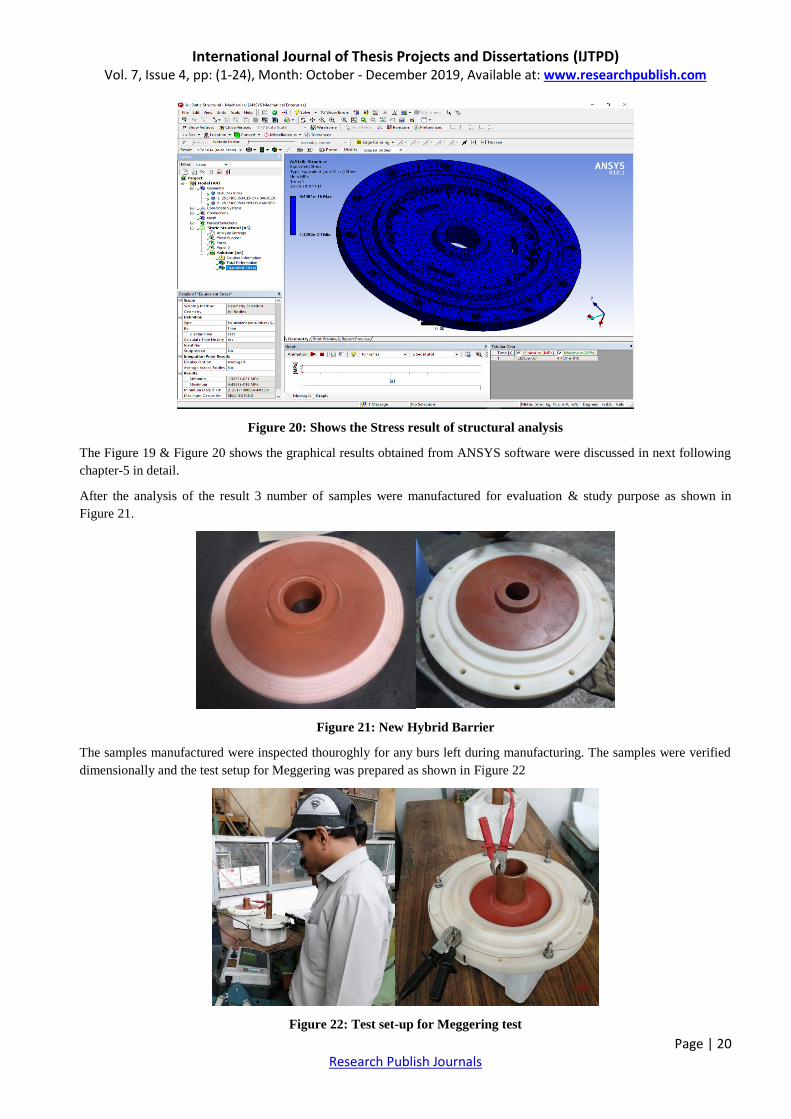
Figure 20: Shows the Stress result of structural analysis
The Figure 19 & Figure 20 shows the graphical results obtained from ANSYS software were discussed in next following
chapter-5 in detail.
After the analysis of the result 3 number of samples were manufactured for evaluation & study purpose as shown in
Figure 21.
Figure 21: New Hybrid Barrier
The samples manufactured were inspected thouroghly for any burs left during manufacturing. The samples were verified
dimensionally and the test setup for Meggering was prepared as shown in Figure 22
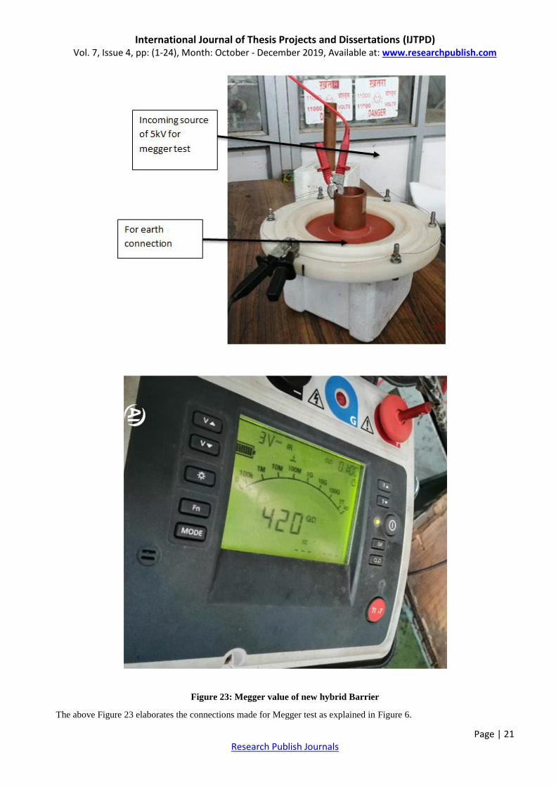
Figure 22: Test set-up for Meggering test
International Journal of Thesis Projects and Dissertations (IJTPD) Vol. 7, Issue 4, pp: (1-24), Month: October - December 2019, Available at: www.researchpublish.com
Page | 21 Research Publish Journals
Figure 23: Megger value of new hybrid Barrier
The above Figure 23 elaborates the connections made for Megger test as explained in Figure 6.

International Journal of Thesis Projects and Dissertations (IJTPD) Vol. 7, Issue 4, pp: (1-24), Month: October - December 2019, Available at: www.researchpublish.com
Page | 22 Research Publish Journals
All three samples manufactured were tested through 5kV Megger test kit applied for 1 minute before and after HV during
which following results were obtained as stated in Table 3: .
Table 3: Test results of megger and HV
W.O. : DEVELOPMENT TEST
PROJECT : DEVELOPMENT OF HYBRID BARRIER FOR GIS APPLICATION
TYPE OF
PRODUCT : GVM36
DATE OF TEST : 27.09.2019
SL. No Megger Value SAMPLE-1 SAMPLE-2 SAMPLE-3
1 Before HV 348GΩ 199GΩ 355GΩ
2 High Voltage 70kV, for 1 min
2 After HV 352GΩ 210GΩ 360GΩ
Figure 24: Prototype under High Voltage testing
Finally, the prototype assembly is subjected to High Voltage testing to ensure proper Di-electric clearances. During this
test, High Voltage of 70kV applied for 1 min. No failure occurred. Leakage current of 12 mA was found which is within
the permissible limits of 1A. Earlier with Nylon barrier, the leakage current up-to 28mA recorded.
Thus after Prototype testing it is evident that the designed Hybrid Barrier is suitable for GIS application of BHEL make,
which has reduced the downtime required during replacement of barrier due to either lower Megger value or due to
Insulation cracks.
International Journal of Thesis Projects and Dissertations (IJTPD) Vol. 7, Issue 4, pp: (1-24), Month: October - December 2019, Available at: www.researchpublish.com
Page | 23 Research Publish Journals
5. RESULTS AND DISCUSSION
The Displacement & Stress analysis conducted on the Hybrid barrier through ANSYS software‟s depicts that the
mechanical load behaviour is unaffected and within the permissible limits of material properties.
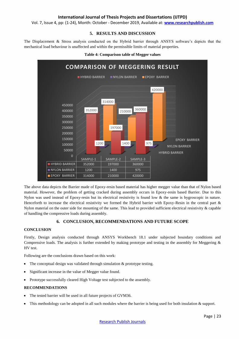
Table 4: Comparison table of Megger values
The above data depicts the Barrier made of Epoxy-resin based material has higher megger value than that of Nylon based
material. However, the problem of getting cracked during assembly occurs in Epoxy-resin based Barrier. Due to this
Nylon was used instead of Epoxy-resin but its electrical resistivity is found low & the same is hygroscopic in nature.
Henceforth to increase the electrical resistivity we formed the Hybrid barrier with Epoxy-Resin in the central part &
Nylon material on the outer side for mounting of the same. This lead to provided sufficient electrical resistivity & capable
of handling the compressive loads during assembly.
6. CONCLUSION, RECOMMENDATIONS AND FUTURE SCOPE
CONCLUSION
Firstly, Design analysis conducted through ANSYS Workbench 18.1 under subjected boundary conditions and
Compressive loads. The analysis is further extended by making prototype and testing in the assembly for Meggering &
HV test.
Following are the conclusions drawn based on this work:
The conceptual design was validated through simulation & prototype testing.
Significant increase in the value of Megger value found.
Prototype successfully cleared High Voltage test subjected to the assembly.
RECOMMENDATIONS
The tested barrier will be used in all future projects of GVM36.
This methodology can be adopted in all such modules where the barrier is being used for both insulation & support.
HYBRID BARRIER
NYLON BARRIER
EPOXY BARRIER
0
50000
100000
150000
200000
250000
300000
350000
400000
450000
SAMPLE-1 SAMPLE-2 SAMPLE-3
HYBRID BARRIER 352000 197000 360000
NYLON BARRIER 1200 1400 975
EPOXY BARRIER 314000 210000 420000
352000
197000
360000
1200 1400 975
314000
210000
420000
COMPARISON OF MEGGERING RESULT
HYBRID BARRIER NYLON BARRIER EPOXY BARRIER
International Journal of Thesis Projects and Dissertations (IJTPD) Vol. 7, Issue 4, pp: (1-24), Month: October - December 2019, Available at: www.researchpublish.com
Page | 24 Research Publish Journals
FUTURE SCOPE OF WORK
o The study can be further extended to use heterogeneous insulating material.
o It can also be manufactured in moulding the epoxy resin cast inside the nylon material which may enhance further.
REFERENCES
[1] BHEL, HANDBOOK OF SWITCHGEARS, BHOPAL: TATA MCGRAW HILL EDUCATION, 2005.
[2] BHEL,“www.bpl.bhel.com/bplweb_new/products/swgr/sw_SF6.htm,”BHEL. [Online]. [Accessed 11 SEPTEMBER
2019].
[3] ELECTRICAL4U,“GIS-or-gas-insulated-switchgear,”[Online].Available:www.electrical4u.com/gis-or-gas-
insulated-switchgear/. [Accessed 10 SEPTEMBER 2019].
[4] MIL-STD-202G, “Resources,” Carlson manufacturing, [Online]. Available: http://carlsonmfg.com/resources/
military-standards-1/2311-mil-std-202g-method-301-pdf-1/file. [Accessed 11 SEPTEMBER 2019].
[5] P. Gill, in Electrical Power Equipment Maintenance and Testing, 1574446568, CRC PRESS, 2009, p. 459.
[6] “Condor Application Note 5/00, pg. 2,” [Online]. Available: https://slpower.com/App-slpower/images/whitepapers/
AN115%20Hipot.pdf. [Accessed 11 SEPTEMBER 2019].
[7] MEGGER, “The Complete Guide to Electrical Insulation Testing,” [Online]. Available: www.techni-tool.com/
site/ARTICLE_LIBRARY/Megger%20-%20The%20Complete%20Guide%20to%20Electrical%20
Insulation%20Testing.pdf. [Accessed 11 SEPTEMBER 2019].
[8] C.-A. Group, “Insulation Resistance Testing Guide,” in https://www.chauvin-arnoux.com/sites/default/files/
D00VEC36.PDF, 906211195 - Ed. 01 - 2010.
[9] Techtarget, “DIELECTRIC MATERIAL,” [Online]. Available: https://whatis.techtarget.com/definition/dielectric-
material. [Accessed 11 SEPTEMBER 2019].
[10] “hybrid-composite,” Science Direct, [Online]. Available: https://www.sciencedirect.com/topics/engineering/hybrid-
composite. [Accessed SEPTEMBER 2019].
[11] R. K. Bharadwaj, “Modelling the barrier properties of polymer-layered silicate nanocomposites,” ACS Publications,
Vols. Avery Research Center, 2900 Bradley Street, Pasadena, California 91107, no. https://doi.org/10.1021/
ma010780b, 2001.
[12] M. F. T. S. M Talaat, “Numerical investigation of the optimal characteristics of a transverse layer of dielectric
barrier in a non-uniform electric field,” Journal of Physics and Chemistry of Solids , vol. 121, no. Pergamon, pp. 27-
35, 2018.
[13] M. J. M. T. N. Saba, Modelling of Damage Processes in Biocomposites, Fibre-Reinforced Composites and Hybrid
Composites, Woodhead Publishing, DECEMBER 2018.
[14] M. M. A. Karakoti, “Finite element modeling of natural fiber-based hybrid composites,” 2018. [Online]. Available:
https://www.researchgate.net/publication/323369061_Finite_element_modeling_of_natural_fiber-
based_hybrid_composites. [Accessed SEPTEMBER 2019].
[15] G. David Cripps, Net Vomposites, JANUARY 2019. [Online]. Available: https://netcomposites.com/guide/resin-
systems/epoxy-resins/. [Accessed SEPTEMBER 2019].
[16] “PROPERTIES AND USES OF NYLON 66,” [Online]. Available: https://blog.oureducation.in/properties-and-uses-
of-nylon-66/. [Accessed SEPTEMBER 2019].
[17] Hhhh A. M. T. R. ANSYS, “Inc. is certified to ISO 9001:2008 Release,” NOVEMBER 2013. [Online]. Available:
http://www.pmt.usp.br/ACADEMIC/martoran/NotasModelosGrad/ANSYS%20Fluent%20Theory%20Guide%2015.
pdf. [Accessed SEPTEMBER 2019].
[18] ANSYS Mechanical Structural Analysis Guide ANSYS, “Inc. is certified to ISO 9001:2008. Release 15.0,”
NOVEMBER 2013. [Online]. Available: https://www.pdfdrive.com/ansys-mechanical-apdl-structural-analysis-
guidepdf-e12262220.html. [Accessed SEPTEMBER 2019].