study of radiographic linear indications and subsequent ... · in gas tungsten arc welds of inconel...
TRANSCRIPT

NASA/TM—2007–215075
September 2007
National Aeronautics andSpace AdministrationIS20George C. Marshall Space Flight CenterMarshall Space Flight Center, Alabama35812
Study of Radiographic Linear Indicationsand Subsequent Microstructural Featuresin Gas Tungsten Arc Welds of Inconel 718J.L. WalleyUniversities Space Research Association, Huntsville, Alabama
A.C. NunesMarshall Space Flight Center, Marshall Space Flight Center, Alabama
J.L. ClounchJacobs ESTS Group, Huntsville, Alabama
C.K. RussellMarshall Space Flight Center, Marshall Space Flight Center, Alabama
https://ntrs.nasa.gov/search.jsp?R=20080002286 2018-06-20T22:47:27+00:00Z

The NASA STI Program…in Profile
Since its founding, NASA has been dedicated to the advancement of aeronautics and space science. The NASA Scientific and Technical Information (STI) Program Office plays a key part in helping NASA maintain this important role.
The NASA STI program operates under the auspices of the Agency Chief Information Officer. It collects, organizes, provides for archiving, and disseminates NASA’s STI. The NASA STI program provides access to the NASA Aeronautics and Space Database and its public interface, the NASA Technical Report Server, thus providing one of the largest collections of aeronautical and space science STI in the world. Results are published in both non-NASA channels and by NASA in the NASA STI Report Series, which includes the following report types:
• TECHNICAL PUBLICATION. Reports of completed research or a major significant phase of research that present the results of NASA programs and include extensive data or theoretical analysis. Includes compilations of significant scientific and technical data and information deemed to be of continuing reference value. NASA’s counterpart of peer-reviewed formal professional papers but has less stringent limitations on manuscript length and extent of graphic presentations.
• TECHNICAL MEMORANDUM. Scientific and technical findings that are preliminary or of specialized interest, e.g., quick release reports, working papers, and bibliographies that contain minimal annotation. Does not contain extensive analysis.
• CONTRACTOR REPORT. Scientific and technical findings by NASA-sponsored contractors and grantees.
• CONFERENCE PUBLICATION. Collected papers from scientific and technical conferences, symposia, seminars, or other meetings sponsored or cosponsored by NASA.
• SPECIAL PUBLICATION. Scientific, technical, or historical information from NASA programs, projects, and missions, often concerned with subjects having substantial public interest.
• TECHNICAL TRANSLATION. English-language translations of foreign scientific and technical material pertinent to NASA’s mission.
Specialized services also include creating custom thesauri, building customized databases, and organizing and publishing research results.
For more information about the NASA STI program, see the following:
• Access the NASA STI program home page at <http://www.sti.nasa.gov>
• E-mail your question via the Internet to <[email protected]>
• Fax your question to the NASA STI Help Desk at 301– 621–0134
• Phone the NASA STI Help Desk at 301– 621–0390
• Write to: NASA STI Help Desk NASA Center for AeroSpace Information 7115 Standard Drive Hanover, MD 21076–1320

�
NASA/TM—2007–215075
Study of Radiographic Linear Indicationsand Subsequent Microstructural Featuresin Gas Tungsten Arc Welds of Inconel 718J.L. WalleyUniversities Space Research Association, Huntsville, Alabama
A.C. NunesMarshall Space Flight Center, Marshall Space Flight Center, Alabama
J.L. ClounchJacobs ESTS Group, Huntsville, Alabama
C.K. RussellMarshall Space Flight Center, Marshall Space Flight Center, Alabama
September 2007
Nat�onal Aeronaut�cs andSpace Adm�n�strat�on
Marshall Space Fl�ght Center • MSFC, Alabama 35812

��
Acknowledgments
The authors would l�ke to acknowledge the follow�ng people from Marshall Space Fl�ght Center’s Mater�als and Processes Laboratory: M�ke Terry, w�th Jeff Norr�s of Lockheed Mart�n Corp., for weld�ng and v�deo support; John Ratl�ff
and Cra�g Bryson for nondestruct�ve �nspect�on; Wendell DeWeese for metallograph�c support; and Preston McG�ll and Mark Talton for mechan�cal test�ng support.
Ava�lable from:
NASA Center for AeroSpace Informat�on7115 Standard Dr�ve
Hanover, MD 21076 –1320301– 621– 0390
Th�s report �s also ava�lable �n electron�c form at<https://www2.st�.nasa.gov>
TRADEMARKS
Trade names and trademarks are used in this report for identification only. This usage does not constitute an official endorsement, e�ther expressed or �mpl�ed, by the Nat�onal Aeronaut�cs and Space Adm�n�strat�on.

���
TABLE OF CONTENTS
1. INTRODUCTION .......................................................................................................................... 1
2. MATERIAL BACKGROUND ....................................................................................................... 2
3. COMMON RADIOGRAPHIC INDICATIONS ............................................................................ 3
4. DEFINITION OF AN ENIGMA .................................................................................................... 5
4.1 D�ffract�on Effects ................................................................................................................... 5 4.2 Segregat�on Effects .................................................................................................................. 6
5. EXPERIMENTAL SETUP ............................................................................................................. 8
5.1 Weld�ng ................................................................................................................................... 8 5.2 Nondestruct�ve Evaluat�on Procedures and Sample Preparat�on Methods ............................. 9
6. OBSERVATIONS ........................................................................................................................... 10
7. MECHANICAL PROPERTIES ..................................................................................................... 22
8. CONCLUSIONS ............................................................................................................................ 24
9. RECOMMENDATIONS FOR DISTINGUISHING RADIOGRAPHIC ENIGMA INDICATIONS FROM DEFECT INDICATIONS ........................................................ 26
APPENDIX A—WELD SETUP ........................................................................................................ 27
APPENDIX B—TRANSFORMATION OF DIFFRACTION ENIGMA IMAGES .......................... 30
B.1 Effect of T�lt�ng the Beam ...................................................................................................... 30
REFERENCES ................................................................................................................................... 33

�v
LIST OF FIGURES
1. A schemat�c en�gma around a large gra�n; l�ght and dark reg�ons on e�ther s�de are due to d�ffract�on .......................................................................................................... 6
2. Weld setup with (a) the AMET system and (b) clamping fixture ....................................... 8
3. Weld sample cut pr�or to mount�ng, pol�sh�ng, and etch�ng to reveal structure ................. 9
4. D�fferently shaped molten puddles: (a) round (JT-03), (b) oval (JT-02), and (c) tear-drop (JT-04). The label BACKSIDE denotes that weld d�rect�on �s upward, that the observer �s look�ng beh�nd the weld puddle ........................................ 10
5. Round-puddle weld (JT-03) show�ng (a) rad�ograph�c and (b) reverse contrast �mages. Not�ce the l�near �nd�cat�on runn�ng the length of the weld po�nted out by the arrows, and the rad�al feather�ng �nd�cat�ons of columnar gra�ns on e�ther s�de. Weld d�rect�on �s from r�ght to left ............................................................. 11
6. Nom�nal weld (JT-02) show�ng (a) rad�ograph�c and (b) reverse contrast �mages. Not�ce the rad�al feather�ng �nd�cat�ons caused by columnar gra�n format�on. Weld d�rect�on �s from left to r�ght ..................................................................................... 11
7. Tear-drop weld (JT-04) show�ng (a) rad�ograph�c and (b) reverse contrast �mages; no v�s�ble lateral �nd�cat�ons or l�near �nd�cat�ons. Vert�cal l�nes are grease penc�l mark�ngs. Weld d�rect�on �s from left to r�ght ........................................ 11
8. Rad�ograph�c �mages of JT-03. The x-ray source was or�ented (a) perpend�cular, (b) +10°, and (c) –10° to the weld panel. The contrast between the dark and l�ght �nd�cat�ons changes w�th the x-ray source or�entat�on. Weld d�rect�on �s st�ll r�ght to left .......................................................................................................................... 12
9. Crown macro of JT-03_1 reg�on. In the center �s a long gra�n w�th a substructure of dendr�tes. The weld d�rect�on �s from top to bottom .............................. 13
10. Crown macro of JT-03_2 reg�on. The l�near reg�on �n the center �s a gra�n compr�sed of dendr�te format�ons. The weld d�rect�on �s from bottom to top ................... 13
11. Transverse macro of JT-03_1. Not�ce that the large dendr�te structure (gra�n) �n the center extends through the depth of the weld. Crown s�de �s up .............................. 14

v
LIST OF FIGURES (Continued)
12. Transverse macro of JT-03_2. Not�ce that the center of the weld lacks a cons�stent large dendr�t�c structure (gra�n) extend�ng through the weld as seen in figure 11. Crown side is up ................................................................................ 14
13. Crown macro of JT-02, nom�nal weld speed. The lateral dendr�tes meet w�th almost d�sjo�nt m�rror symmetry at the center of the weld jo�nt ................................ 15
14. Crown macro enlarged of JT-02, nom�nal weld speed. Not�ce conjunct�on of lateral dendr�tes at the center of the weld. The weld d�rect�on �s from bottom to top ................... 15
15. Crown macro of JT-04. Not�ce there �s no relat�ve or�entat�on preference for the dendr�te format�ons. Not�ce that weld d�rect�on �s �nd�scern�ble for th�s jo�nt ....... 16
16. Crown macro enlarged of JT-04. Not�ce there �s no relat�ve or�entat�on preference for the dendr�te format�ons ................................................................................................. 16
17. Rad�ograph�c �mage of JT-05. The m�smatch �nd�cat�on can be seen as a l�ght �mage w�th a darker �mage super�mposed over the lower part of the weld. Weld d�rect�on �s left to r�ght .............................................................................................. 17
18. Transverse macro of JT-05. Not�ce the v�s�ble m�smatch on the root s�de ......................... 17
19. Segment of weld JT-08. The bead has been d�splaced toward the r�ght unt�l �t has been moved almost off the joint (see transverse section fig. 21), which can be seen extend�ng from the left edge of the bead. At th�s po�nt, the jo�nt �s only be�ng part�ally consumed by the weld bead ............................................................................................... 18
20. Rad�ograph�c �mage of JT-08 show�ng lack of fus�on at the arrow where the cross-sl�de mot�on was used to move the bead back toward the center of the jo�nt: (a) �s the rad�ograph�c �mage; (b) �s the reverse contrast �mage. Under the rad�ograph�c contrast cond�t�ons shown, the unwelded jo�nt �s extend�ng to the left from the v�s�ble �nd�cat�on �s not v�s�ble. Weld d�rect�on �s from left to r�ght ............................................. 18
21. Transverse macro of weld JT-08, where a m�ssed jo�nt can be seen on the left s�de of the �mage. The crown �s on the top ....................................................... 19
22. Rad�ograph of JT-08 taken at –10° off perpend�cular. A fa�nt en�gma �nd�cat�on can be seen near the start of the weld jo�nt. Weld d�rect�on �s left to r�ght ........................ 19
23. Rad�ograph of JT-08 taken +10° off perpend�cular. The l�near �nd�cat�on caused by lack of fus�on can be seen along the top of the crown re�nforcement. Weld d�rect�on �s left to r�ght ....................................................................................................... 20

v�
LIST OF FIGURES (Continued)
24. Rad�ograph of JT-08 w�th x-ray source or�ented perpend�cular to the jo�nt. The lack of fus�on, m�ssed jo�nt can be seen as a blurry dark l�ne along the bottom of the �mage. Th�s �mage has been reversed w�th respect to the prev�ous �mage ......................................................................................................... 20
25. A compar�son of rad�ographs w�th x-ray source at (a) +10°, (b) perpend�cular, and (c) –10°. Not�ce that the l�near �nd�cat�on caused by lack of penetrat�on moves �n the weld puddle but does not substant�ally change clar�ty or s�ze. Weld d�rect�on �s r�ght to left ...................................................................................................................... 21
26. Transverse macro of JT-09. The lack of penetrat�on can be seen �n the center of the weld near the root s�de ........................................................................ 21
27. Diffraction condition for reflection from reciprocal lattice point h00 ................................ 30
28. Format�on of an �mage by a large d�ffract�ng crystal embedded �n an amorphous med�um. The sh�ft �n beam power by the d�ffract�ng component of the �nc�dent beam affects power �ntens�ty at the �mage boundar�es ....................................................... 31
v��
LIST OF TABLES
1. Inconel 718 nom�nal alloy compos�t�on (wt%) .................................................................... 2
2. L�near �nd�cat�on w�dth (�nches) at three locat�ons on the rad�ographs ............................... 12
3. A compar�son of reference tens�le propert�es and exper�mental propert�es of parent metal and welded spec�mens ................................................................................. 22
4. Stat�st�cal results of the tens�le data ..................................................................................... 23
5. Relat�onsh�p of movement of a d�ffract�on �mage w�th angular d�splacement of �nc�dent x-ray beam .......................................................................................................... 31

v���
LIST OF ACRONYMS AND SYMBOLS
Al alum�num
AMET Automated Manufactur�ng Eng�neer�ng Technolog�es
C carbon
Cr chrom�um
Cu copper
Fe �ron
GTAW gas tungsten arc weld�ng
Mo molybdenum
Nb n�ob�um
NDE nondestruct�ve evaluat�on
N� n�ckel
T� t�tan�um
UTS ult�mate tens�le strength
VPPA var�able polar�ty plasma arc

�x
NOMENCLATURE
a parameter
h coord�nate of rec�procal latt�ce po�nt hkl
I �ntens�ty
L effect�ve d�stance from the d�ffract�ng body
w w�dth
x d�stance traveled
φ angle of reflected beam
λ wavelength
θ angle of rec�procal latt�ce
µ absorption coefficient

x

1
TECHNICAL MEMORANDUM
STUDY OF RADIOGRAPHIC LINEAR INDICATIONS AND SUBSEQUENT MICROSTRUCTURAL FEATURES IN GAS TUNGSTEN ARC WELDS OF INCONEL 718
1. INTRODUCTION
Assessment of the �ntegr�ty of a weld �s a compl�cated, nondestruct�ve evaluat�on (NDE) problem that can be challeng�ng to even the most tra�ned spec�al�st. Many of today’s aerospace mater�als, such as Inconel® 718 (reg�stered trade name of Inco Alloys Internat�onal, Inc.) (AMS 5596J) do not have a set of reference gu�des for the spec�al�st to make compar�sons. Th�s makes �dent�fy�ng hazardous defect �nd�cat�ons an art form, subject to personal acu�ty, exper�ence, and �nterpretat�ons. Th�s study was con-ducted to produce l�near rad�ograph�c �nd�cat�ons from 0.05-�n-th�ck Inconel 718 butt welds and to �den-t�fy the m�crostructural elements caus�ng each of the �nd�cat�ons.
The focus of th�s study was to prov�de a procedure for d�fferent�at�ng d�fferent types of �nd�ca-t�ons l�ke en�gma, or ‘ghost,’ �nd�cat�ons from �nd�cat�ons produced by potent�ally hazardous defects. An en�gma �nd�cat�on can be m�s�nterpreted as der�v�ng from real weld defects such as lack of fus�on or penetrat�on, but are caused by some other structural character�st�c that may or may not be detr�men-tal to the �ntegr�ty of the weld jo�nt. En�gmas have been found �n var�able polar�ty plasma arc (VPPA) welds of aluminum alloys due to elemental segregation of copper (Cu) during solidification. The purpose of th�s study was to further the understand�ng of the format�on of en�gmas �n Inconel 718 weld rad�o-graphs1 so that more accurate �nterpretat�ons can be accompl�shed dur�ng NDE.
Initial information has been provided on the material under investigation, a definition of a radio-graph�c en�gma, and a h�ghl�ght of some of �ts common structural causes. The exper�mental procedures used �n th�s �nvest�gat�on to produce nom�nal welds, en�gma �nd�cat�ons, and defect �nd�cat�ons have been expla�ned. Rad�ograph�c and m�croscop�c observat�ons have also been expla�ned and compared, as well as eddy current and penetrant observat�ons on select weld jo�nts. F�nd�ngs have been summar�zed and recommendat�ons made for d�st�ngu�sh�ng rad�ograph�c en�gma �nd�cat�ons from �nd�cat�ons pro-duced by defects.

2
2. MATERIAL BACKGROUND
Inconel 718 �s a n�ob�um (Nb)-strengthened n�ckel (N�)-�ron (Fe) superalloy. Nom�nal compos�-t�on �s g�ven �n table 1. The Nb content acts to strengthen the alloy through prec�p�tates of γ ″ part�cles of the N�3Nb ordered, face centered cub�c phase. These prec�p�tates l�m�t the solub�l�ty of the γ ′ phase, N�3(T�, Al), also used to harden N�-Fe superalloys. Both of these prec�p�tates g�ve the N�-Fe superalloy �ts h�gher strength at elevated temperatures; th�s �s due to res�stance to d�slocat�on cutt�ng through the precipitates. The added benefit of γ ″, wh�ch forms around the γ ′ part�cles, �s �ts slow transformat�on rate. Th�s greatly enhances the weldab�l�ty of the superalloy over others because �t does not �nstantly �nduce harden�ng and consequent postweld crack�ng.2–4 The overall complex�ty of th�s structure causes a tendency toward dendr�te format�on dur�ng weld�ng.5,6
Table 1. Inconel 718 nom�nal alloy compos�t�on (wt%).4
Ni Cr Mo Nb Ti Al Fe C Cu
53 19 3 5.1 0.9 0.5 18.5 0.08 0.15

3
3. COMMON RADIOGRAPHIC INDICATIONS
Determ�n�ng a method for d�scern�ng d�fferent defects by means of the�r rad�ograph�c l�near �nd�cat�ons as observed �n gas tungsten arc weld�ng (GTAW) welds was the �ntent�on of th�s study. Each defect �s assoc�ated w�th a d�fferent type of �nd�cat�on. Examples of defects and the�r common �nd�ca-t�ons as presented �n the NondestructiveTestingHandbook are l�sted below:7
• Incomplete (or lack of) penetrat�on �s an absence of fus�on at the weld root. It may be caused by an insufficiently hot root pass. It is indicated by a broad line along the weld. The line may be located along the weld centerl�ne or be offset depend�ng upon the al�gnment of the weld bead w�th the weld seam. The w�dth of the �nd�cat�on �s a funct�on of the amount of �ncomplete penetrat�on.
• Incomplete (or lack of) fus�on �s an absence of fus�on between a weld bead and adjacent metal. It may be caused by �mproper weld�ng techn�que. The unfused gap tends to be narrow and to produce a sharp, dark l�ne �nd�cat�on when l�ned up along the x-ray beam.
• Tungsten �nclus�ons (from a GTAW electrode) are usually denser than the weld metal and appear as l�ght spots on a rad�ograph.
• Shr�nkage compr�ses �rregular cav�t�es or d�str�but�ons of �rregular cav�t�es. It occurs when a sol�d�fy�ng volume of molten metal �s sealed off from a source of replen�sh�ng molten metal so that cav�t�es open up between sol�d�fy�ng dendr�tes. Ind�cat�ons are dark and may range from shadowed areas for a distribution of microshrinkage to well-defined irregular figures.
• Poros�ty compr�ses rounded cav�t�es or d�str�but�ons of rounded cav�t�es. It �s caused by the freez�ng of gas bubbles �n sol�d�fy�ng molten metal or �n sol�d metal soft enough to be deformed by the pressure of an emerg�ng gas. Ind�cat�ons are dark and may range from shadowed areas for a distribution of microporosity to well-defined circular spots from spherical pores or lines from cont�nuous d�str�but�ons of pores (‘p�p�ng poros�ty,’ ‘wormhole poros�ty,’ ‘or hollow bead’).
• Cracks result when stresses w�th�n the weld metal exceed the fracture stress capab�l�ty of the metal. Dynam�c thermal stresses act�ng on hot weld metal produce ‘hot cracks’; res�dual stresses act�ng on cold weld metal produce ‘cold cracks’ or ‘delayed cracks.’ Crack morphology �s w�dely var�ed. Crack �nd�cat�ons on a rad�ograph are dark, and vary w�dely w�th the morphology.

4

5
4. DEFINITION OF AN ENIGMA
In a rad�ograph�c context, an en�gma �s an �nd�cat�on from a weld lack�ng an obv�ous correspond-�ng structural feature. En�gmas are not usually cons�dered harmful to the �ntegr�ty of a weld, although the nature of the underly�ng structure respons�ble for the en�gma must be cons�dered before d�sm�ss�ng �t as a harmless �nd�cat�on. Lack of obv�ous structural character�st�c does not guarantee harmlessness. Dur�ng NDE, �t �s �mportant to �dent�fy en�gmas unamb�guously. If th�s cannot be done, the �nd�cat�on must be treated as a defect �nd�cat�on even when �ts nature as an en�gma �s suspected. These are two common structural features that produce rad�ograph�c en�gmas—large gra�ns, where en�gmas are gener-ated by d�ffract�on, and segregat�on, where en�gmas are generated by d�fferent�al absorpt�on of rad�at�on. Although other unobtrus�ve structural features m�ght conce�vably produce en�gma �nd�cat�ons, the con-trast mechan�sms by wh�ch en�gmas are generated are l�m�ted to d�ffract�on and d�fferent�al absorpt�on.
4.1 Diffraction Effects
Dur�ng rad�ography, a polychromat�c x-ray beam �mp�nges on an object. The transm�tted beam induces a chemical transformation in photographic film or affects some other medium to map the trans-mitted beam intensity over the object. The more intense the transmitted beam, the darker the film will be. Image contrast �s due to d�fferences �n �ntens�ty of the transm�tted beam through the cross sect�on caused by var�at�ons �n absorpt�on of the transm�tted beam by the �nternal structure of the object be�ng examined. The transmitted beam creates a reverse shadow effect on the film, since the intensity of x-ray transm�tted �s fract�onally reduced proport�onal to the dens�ty of the object. The l�ghter the rad�ograph�c �mage produced, the denser the sample. Cracks or vo�ds absorb less of the transm�tted beam and show up on film as dark lines or spots. Welds show up as light regions because of extra metal deposited above and below the surface of the parent metal, present�ng more mater�al to absorb the transm�tted beam.
Somet�mes large gra�ns at appropr�ate or�entat�ons g�ve r�se to d�ffract�on effects super�mposed on the rad�ograph�c �mage. The structural features of the object generat�ng a d�ffract�on effect are, �n general, less cr�t�cal to weld �ntegr�ty than the defects that generate absorpt�on contrast effects. But somet�mes d�ffract�on effects can masquerade as absorpt�on contrast effects caused by defects. When th�s occurs and the defect ant�c�pated from the contrast effect �s not to be found when the object �s cut open, the radiographic effect is classified as a ‘ghost’ or ‘enigma.’ It should be noted that relatively harmless segregates may also cause �nd�cat�ons suggest�ng defects. Not all en�gmas are d�ffract�on effects. An x-ray rad�ograph for a polycrystall�ne mater�al may be compared to a transm�ss�on Laue d�f-fract�on pattern w�th only the central transm�tted spot observed. Th�s �s because for the usual polycrys-tall�ne object, Laue d�ffract�on effects cancel out, produc�ng only one transm�tted spot. But somet�mes large gra�ns, or dendr�tes �n fus�on welds, are present and d�ffract�on patterns emerge because of the polychromat�c source. A d�ffracted beam produces an �mage of the d�ffract�ng body. The �mage �s sh�fted w�th respect to the transm�tted �mage by the d�ffract�on angle. The �ntens�ty of rad�at�on �s reduced �n places vacated by the d�ffract�on �mage and �ncreased �n places entered by the d�ffracted �mage. Th�s produces shadow�ng effects around the d�ffract�on �mage. Th�s d�ffract�on produces l�ght and dark

6
contrasts on oppos�te s�des of the d�ffract�on �mage of the d�ffract�ng gra�n because the d�ffracted �mage adds or subtracts from e�ther s�de. F�gure 1 shows an example of such a d�ffract�on pattern.
F�gure 1. A schemat�c en�gma around a large gra�n; l�ght and dark reg�ons on e�ther s�de are due to d�ffract�on.
4.2 Segregation Effects
As a beam of rad�at�on passes through a body, the �ntens�ty of the beam d�m�n�shes, some of the beam be�ng converted �nto heat and some d�ffracted away from the d�rect�on of the penetrat�ng beam. The �ntens�ty (I) of the beam drops w�th d�stance traveled (x) accord�ng to the relat�on dI/dx = –μI, where μ is the absorption coefficient for the beam. If a hole or crack exists in a material, it acts as a spot of reduced absorpt�on for any beam cross�ng �t, and ra�ses the transm�tted x-ray �ntens�ty so as to become visible as a dark (more exposed) indication on detecting film. If, instead of a hole, there is a region of elemental segregation in a material, the absorption coefficient can be either lower or higher, producing a dark or l�ght �nd�cat�on, depend�ng on the dens�ty d�fferences between the segregated element and the surround�ng mater�al.
Segregation occurs during solidification from a melt. As the freezing interface moves forward, the newly formed sol�d ejects solute �nto the l�qu�d phase. As freez�ng progresses, both newly sol�d�-fied solid phase and the remaining liquid phase take on higher concentrations of solute. Typically, this k�nd of segregat�on man�fests �tself on a small scale and �s not l�kely to be v�s�ble at the macroscale of a rad�ograph. In m�crographs, pol�shed and etched dendr�tes are clearly v�s�ble. The �nterdendr�t�c metal be�ng more h�ghly alloyed tends to be attacked more v�gorously by an etch. Hence, the �nterdendr�t�c etched surface tends to be rougher than that of the dendrite core and tends to be darker in bright field contrast.
If, however, a partially solidified metal is subjected to pressure, the pressure can drive the rema�n�ng l�qu�d phase w�th �ts relat�vely h�gh solute concentrat�on to m�grate on a macroscop�c scale. Thermal stresses �n welds may produce such pressures. The resultant segregat�on structure may produce variations in transmitted x-ray intensity and produce visible indications on detecting film. Such segre-gat�on structures are not usually cons�dered harmful to the �ntegr�ty of a weld and the�r �nd�cat�ons are usually classed as en�gmas. It �s necessary to be caut�ous, however. Second phase coarsen�ng, suggest�ng

7
segregat�on as descr�bed above, has been found at the toes of GTAW welds. Th�s may correlate w�th a reduct�on �n strength of welds w�th �ntact re�nforcements. Pend�ng further study, th�s m�ght expla�n why, �n some cases, the removal of weld re�nforcements �ncreases weld strength. The actual drop �n strength here �s not attr�buted to segregat�on per se, but rather to the assoc�ated coarsen�ng of a phase.

8
5. EXPERIMENTAL SETUP
5.1 Welding
An Automated Manufactur�ng Eng�neer�ng Technolog�es (AMET) GTAW system was used to jo�n 12-�n-long × 6-�n-w�de × 0.05-�n-th�ck Inconel 718 panels w�th a s�ngle-pass butt weld. The setup �s shown in figure 2 and weld settings for the subsequent experiments can be found in appendix A. A cam-era was set up to v�deo record �n s�tu weld puddle var�at�ons beh�nd the torch dur�ng exper�ments.
(a) (b)
Figure 2. Weld setup with (a) the AMET system and (b) clamping fixture.
A first set of experiments was conducted to determine the nominal parameters using bead-on-plate welds both with and without filler wire. After observations of video footage of the weld operations, it was concluded that for ease of visibility, filler wire would be used for the subsequent joint welds. No rad�ography was conducted on the bead-on-plate exper�ments.
Us�ng the bead-on-plate exper�ments as a start�ng po�nt for nom�nal sett�ngs, �t was dec�ded that var�at�ons �n travel speed would be used to man�pulate the weld puddle shape. A second set of exper�-ments determ�ned travel speed var�at�ons for round, oval (nom�nal), and tear-drop-shaped puddles.
F�nally, separate panels were welded together �n a jo�nt w�th var�at�ons �n cross-sl�de d�splace-ment, and then w�th var�at�ons �n current to produce lack of fus�on and lack of penetrat�on, respect�vely. Th�s was done so that a compar�son could be made between en�gma and defect rad�ograph�c �nd�cat�ons. A table of weld parameters for each jo�nt pass �s located �n append�x A. No heat treatment was con-ducted on any of the weld panels for th�s exper�ment.
9
5.2 Nondestructive Evaluation Procedures and Sample Preparation Methods
Rad�ograph�c NDE was conducted on all of the jo�nt panels (JT-01 through JT-09). On several of the panels, mult�ple rad�ographs were taken to determ�ne �f d�fferences �n x-ray or�entat�on (±10° off perpend�cular) produced any d�fferences �n s�ze, clar�ty, or locat�on of the parallel l�near �nd�cat�on.
NDE standards say that all areas of interest should be x-rayed such that the film density, deter-m�ned w�th a dens�tometer, �s between two (1% l�ght transm�ss�on) and four (0.01% l�ght transm�ss�on).7 The density of the film is the base-10 logarithm of the intensity of the incident light from a densitometer source d�v�ded by the transm�tted �ntens�ty. If all areas of �nterest cannot be d�splayed �n a s�ngle p�cture, then mult�ple x-ray �mages should be taken. Th�s �s part�cularly �mportant s�nce the welded area �s much denser than the parent metal, making it difficult to inspect for cracks, or missed joint indication in both parent metal and welded area w�th the same rad�ograph. It �s �mportant to note, that except for JT-08, the film density requirements standards were not followed.
Qual�tat�ve eddy current test�ng was conducted on the en�gma panel and the two defect panels for compar�son of results. Penetrant test�ng was conducted on the lack-of-fus�on weld (JT-08).
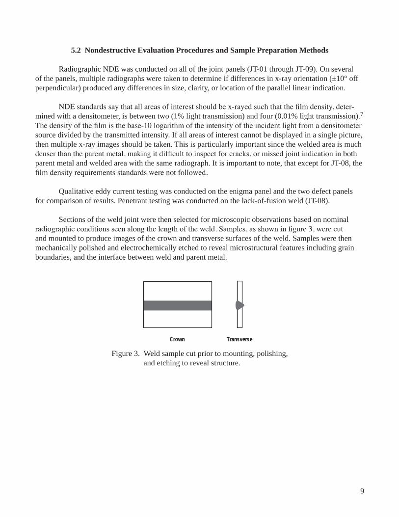
Sect�ons of the weld jo�nt were then selected for m�croscop�c observat�ons based on nom�nal radiographic conditions seen along the length of the weld. Samples, as shown in figure 3, were cut and mounted to produce �mages of the crown and transverse surfaces of the weld. Samples were then mechan�cally pol�shed and electrochem�cally etched to reveal m�crostructural features �nclud�ng gra�n boundar�es, and the �nterface between weld and parent metal.
Crown Transverse
F�gure 3. Weld sample cut pr�or to mount�ng, pol�sh�ng, and etch�ng to reveal structure.

10
6. OBSERVATIONS
Puddle shape �s determ�ned by the rat�o of the speed at wh�ch the puddle edge freezes to the rate at wh�ch the weld heat source �s moved; �.e., the weld travel speed. When the freez�ng rate of the weld metal �s apprec�ably faster than the weld travel speed, the back edge of the weld puddle eas�ly keeps up w�th the travel speed and the back edge of the puddle �s round. When the freez�ng rate of the weld metal �s apprec�ably slower than the weld travel speed, the molten metal extends back from the weld heat source and the puddle edges move �n from the s�des along stra�ght l�nes, end�ng �n a po�nt and mark�ng out a tear-drop shape for the weld puddle. Between these two extremes, the weld puddle takes an ell�pt�-cal shape. Travel speed, from 2 �n/m�n to 7.5 �n/m�n, greatly changed the appearance of the molten weld puddle.
The round weld puddle, as seen in figure 4(a), was a feature of slowest travel speed (JT-03), and was accompan�ed by excess�ve root re�nforcement and m�n�mal crown re�nforcement. Th�s was also the largest of the weld puddles, w�th the puddles gett�ng progress�vely smaller as the travel speed �ncreased and heat �nput per un�t length of weld decreased.
Dur�ng the nom�nal weld sett�ngs (JT-02), the welders observed an oval-shaped weld puddle (fig. 4(b)) and postweld inspections showed an appropriate amount of reinforcement.
The tear-drop weld puddle (fig. 4(c)) was created using the fastest travel speed (JT-04). It had excess�ve crown re�nforcement and l�ttle root re�nforcement, �n contrast to the round weld puddle. Also, mismatch caused by inadequate clamping forces from the fixture was seen near the end of several pan-els, most not�ceable on panel JT-05. Reduced puddle s�ze at the faster travel speeds made �t eas�er to �dent�fy jo�nt m�smatch.
(a) (b) (c)
F�gure 4. D�fferently shaped molten puddles: (a) round (JT-03), (b) oval (JT-02), and (c) tear-drop (JT-04). The label BACKSIDE denotes that weld d�rect�on �s upward, that the observer �s look�ng beh�nd the weld puddle.
The rad�ograph�c �mages showed that the slower the travel speed, the more prevalent the l�near en�gma �nd�cat�ons were, both �n the rad�al d�rect�on and the d�rect�on parallel to the jo�nt. The slowest travel speed, the one w�th the most heat �nput, produced substant�al l�near �nd�cat�ons parallel to the jo�nt

11
and radial indications on either side of the parallel indication as shown in figure 5. The radiographs from the nominal weld speed showed only radial indications (fig. 6). These radial indications are caused by columnar grain structures with a dendritic core elongated in the direction of solidification. The fastest travel speed produced no radiographic linear or radial indication (fig. 7).
(a)
(b)
F�gure 5. Round-puddle weld (JT-03) show�ng (a) rad�ograph�c and (b) reverse contrast �mages. Not�ce the l�near �nd�cat�on runn�ng the length of the weld po�nted out by the arrows, and the rad�al feather�ng �nd�cat�ons of columnar gra�ns on e�ther s�de. Weld d�rect�on �s from r�ght to left.
(a)
(b)
F�gure 6. Nom�nal weld (JT-02) show�ng (a) rad�ograph�c and (b) reverse contrast �mages. Not�ce the rad�al feather�ng �nd�cat�ons caused by columnar gra�n format�on. Weld d�rect�on �s from left to r�ght.
(a)
(b)
F�gure 7. Tear-drop weld (JT-04) show�ng (a) rad�ograph�c and (b) reverse contrast �mages; no v�s�ble lateral �nd�cat�ons or l�near �nd�cat�ons. Vert�cal l�nes are grease penc�l mark�ngs. Weld d�rect�on �s from left to r�ght.

12
The radiographs seen in figure 8 were then taken of JT-03 with the x-ray source oriented at ±10° to the or�g�nal perpend�cular pos�t�on. The three d�fferent x-ray source angles produced three d�fferent �mages at the same locat�on �n the weld jo�nt. The �nd�cat�ons never d�sappeared or changed locat�on, but they d�d change s�ze and clar�ty. Measurements on overall th�ckness of the �nd�cat�ons were taken and summar�zed �n table 2. They showed that the th�ckness of the l�near �nd�cat�on �ncreased as the x-ray source was moved from –10° to 0° to +10° or�entat�ons.
(a)
(b)
(c)
Perpendicular
10°
–10°
F�gure 8. Rad�ograph�c �mages of JT-03. The x-ray source was or�ented: (a) perpend�cular, (b) +10°, and (c) –10° to the weld panel. The contrast between the dark and l�ght �nd�cat�ons changes w�th the x-ray source or�entat�on. Weld d�rect�on �s st�ll r�ght to left.
Table 2. L�near �nd�cat�on w�dth (�nches) at three locat�ons on the rad�ographs.
Radiograph Location
(in)
X-ray Orientation to Panel
–10° 0° 10°
26.59
0.00710.00470.0039
0.00790.00550.0055
0.00870.00710.0063

13
The slowest travel speed (JT-03) was cut �nto macros at two locat�ons—one where the l�near indications parallel to the joint were easily defined as a dark and light line pair (JT-03_1) and the sec-ond �n a locat�on where there was only one grey �nd�cat�on (JT-03_2). The macros from both locat�ons showed that long�tud�nal columnar dendr�te structures were formed parallel to the jo�nt, wh�ch was easy to see in the crown macros in figures 9 and 10. The transverse cross sections show that at the JT-03_1 location (fig. 11) columnar dendrites are lined up through the depth of the weld, with a consistent bound-ary and th�ckness through the depth of the weld. In contrast, the transverse macro from JT-03_2 showed that the boundar�es between parallel columnar dendr�tes and the rest of the weld nugget are not parallel to each other and the reg�on’s th�ckness �s also not cons�stent through the depth of the weld as seen �n figure 12.
1 mm
F�gure 9. Crown macro of JT-03_1 reg�on. In the center �s a long gra�n w�th a substructure of dendr�tes. The weld d�rect�on �s from top to bottom.
1 mm
F�gure 10. Crown macro of JT-03_2 reg�on. The l�near reg�on �n the center �s a gra�n compr�sed of dendr�te format�ons. The weld d�rect�on �s from bottom to top.

14
1 mm
500 µm
F�gure 11. Transverse macro of JT-03_1. Not�ce that the large dendr�te structure (gra�n) �n the center extends through the depth of the weld. Crown s�de �s up.
1 mm
500 µm
F�gure 12. Transverse macro of JT-03_2. Not�ce that the center of the weld lacks a cons�stent large dendr�t�c structure (gra�n) extend�ng through the weld as seen in figure 11. Crown side is up.
The crown macro (fig. 13) for the nominal weld speed (JT-02) shows that the lateral dendrite format�ons come together at the center of the weld and create a d�sjo�nt m�crostructure �n the absence of any longitudinal dendrite formations. At higher magnification (fig. 14), it can be seen that these dendrites produce a v�s�ble boundary. Th�s �mpl�es that the weld speed �s somewhat h�gher than the rate of freez-ing, even though the puddle appeared to have an elliptical shape with a flat perimeter at the trailing edge.

15
1 mm
F�gure 13. Crown macro of JT-02, nom�nal weld speed. The lateral dendr�tes meet w�th almost d�sjo�nt m�rror symmetry at the center of the weld jo�nt.
250 µm
F�gure 14. Crown macro enlarged of JT-02, nom�nal weld speed. Not�ce conjunct�on of lateral dendr�tes at the center of the weld. The weld d�rect�on �s from bottom to top.

16
The crown macro for the tear-drop weld speed (JT-04) shows a random equ�axed dendr�te or�en-tation (fig. 15). The higher magnification (fig. 16) verifies this random configuration. The relatively high solidification velocity of the fastest weld speed apparently does not allow time for columnar formation s�nce the transformat�on k�net�cs of the Inconel 718 structure �s slow.
1 mm
F�gure 15. Crown macro of JT-04. Not�ce there �s no relat�ve or�entat�on preference for the dendr�te format�ons. Not�ce that weld d�rect�on �s �nd�scern�ble for th�s jo�nt.
500 µm
F�gure 16. Crown macro enlarged of JT-04. Not�ce there �s no relat�ve or�entat�on preference for the dendr�te format�ons.

17
Subsequent weld exper�ments were conducted to produce m�smatch, lack of fus�on, and lack of penetrat�on �nd�cat�ons.
By vary�ng the clamp�ng pressure on the panels dur�ng weld�ng, the welders were able to pro-duce a joint with significant mismatch, near the end of the panel. From the radiographic image (fig. 17), �t can be seen that th�s m�smatch created an �nd�cat�on �n the form of an ∼0.01-�n l�ght and dark reg�on on e�ther s�de of a boundary runn�ng approx�mately along the m�ddle of the weld. The macro �mage of figure 18 explains the indication. The crown is flat, but there is a step at the weld root, such that the thickness penetrated by the x-ray beam is significantly different on opposing sides of the step.
F�gure 17. Rad�ograph�c �mage of JT-05. The m�smatch �nd�cat�on can be seen as a l�ght �mage w�th a darker �mage super�mposed over the lower part of the weld. Weld d�rect�on �s left to r�ght.
1 mm
F�gure 18. Transverse macro of JT-05. Not�ce the v�s�ble m�smatch on the root s�de.
The lack of fus�on weld was created by cross sl�d�ng the weld puddle unt�l the jo�nt was seen just at the edge of the crown reinforcement (fig. 19). The radiograph showed a blurry dark line at the position where the cross slide moved the bead back to the middle of the joint (fig. 20) but there was no visible �nd�cat�on for the rema�n�ng length of the m�ssed jo�nt. The macro shows that there was almost complete lack of fusion for the length of the joint (fig. 21). Penetrant testing was conducted on JT-08 and produced v�s�ble poros�ty �nd�cat�ons on the root s�de of the weld along the length of the jo�nt.

18
F�gure 19. Segment of weld JT-08. The bead has been d�splaced toward the r�ght unt�l �t has been moved almost off the joint (see transverse section fig. 21), which can be seen extend�ng from the left edge of the bead. At th�s po�nt, the jo�nt �s only be�ng part�ally consumed by the weld bead.
(a)
(b)
F�gure 20. Rad�ograph�c �mage of JT-08 show�ng lack of fus�on at the arrow where the cross-sl�de mot�on was used to move the bead back toward the center of the jo�nt: (a) �s the rad�ograph�c �mage; (b) �s the reverse contrast �mage. Under the rad�ograph�c contrast cond�t�ons shown, the unwelded jo�nt extend�ng to the left from the v�s�ble �nd�cat�on �s not v�s�ble. Weld d�rect�on �s from left to r�ght.

19
1 mm
F�gure 21. Transverse macro of weld JT-08, where a m�ssed jo�nt can be seen on the left s�de of the �mage. The crown �s on the top.
X-rays of JT-08 were also taken at ±10° of the or�g�nal x ray. The –10° panel d�d not show a l�near �nd�cat�on for the lack of fus�on, but �t d�d produce a l�near en�gma �nd�cat�on near the beg�nn�ng of the weld that was not observed of either the perpendicular or +10° radiograph (fig. 22). The +10° panel showed a dark l�near �nd�cat�on produced by the lack of fus�on under the crown re�nforcement along the length of the weld (fig. 23).
F�gure 22. Rad�ograph of JT-08 taken at –10° off perpend�cular. A fa�nt en�gma �nd�cat�on can be seen near the start of the weld jo�nt. Weld d�rect�on �s left to r�ght.

20
F�gure 23. Rad�ograph of JT-08 taken +10° off perpend�cular. The l�near �nd�cat�on caused by lack of fus�on can be seen along the top of the crown re�nforcement. Weld d�rect�on �s left to r�ght.
When the proper rad�ograph�c standards are followed, and the �mage dens�ty of the parent metal �s w�th�n the 2 to 4 dens�ty range, the m�ssed jo�nt �s clearly v�s�ble �n the rad�ograph taken perpend�cular to the joint (fig. 24).
F�gure 24. Rad�ograph of JT-08 w�th x-ray source or�ented perpend�cular to the jo�nt. The lack of fus�on, m�ssed jo�nt can be seen as a blurry dark l�ne along the bottom of the �mage. Th�s �mage has been reversed w�th respect to the prev�ous �mage.
Lack of penetrat�on �n the center of the weld jo�nt was created by reduc�ng the weld current enough to decrease the penetrat�on depth wh�le st�ll ma�nta�n�ng a stable puddle. Lack of penetrat�on in weld JT-09 produced a dark indication of the weld joint (fig. 25(b)). X-ray orientations at ±10° of perpendicular produced the radiographs seen in figure 25(a) and (c), respectively. The linear indica-t�on moved up and down, above and below the center of the weld jo�nt, but d�d not change �ntens�ty or appearance apprec�ably at these low angle change �ncrements. F�gure 26 shows the lack of penetrat�on respons�ble for these �nd�cat�ons.

21
(a)
(b)
(c)
F�gure 25. A compar�son of rad�ographs w�th x-ray source at (a) +10°, (b) perpend�cular, and (c) –10°. Not�ce that the l�near �nd�cat�on caused by lack of penetrat�on moves �n the weld puddle but does not substant�ally change clar�ty or s�ze. Weld d�rect�on �s r�ght to left.
1 mm
F�gure 26. Transverse macro of JT-09. The lack of penetrat�on can be seen �n the center of the weld near the root s�de.
Eddy current test�ng, us�ng a two-co�l probe, was conducted on panels JT-03, JT-08, and JT-09. The l�near dendr�te format�ons that caused the en�gma �nd�cat�on �n JT-03 produced no eddy current �nd�-cat�ons and passed �nspect�on. Lack of fus�on and lack of penetrat�on as exh�b�ted by JT-08 and JT-09, respect�vely, d�d not pass eddy current �nspect�on. JT-08 produced an �nd�cat�on, but the operator was unsure about the s�ze of the defect caus�ng the �nd�cat�on. The eddy current data were representat�ve of e�ther a very shallow and/or narrow defect runn�ng the length of the weld on the root s�de. The eddy cur-rent data for JT-09 �nd�cated a narrow root s�de lack of penetrat�on along the center of the weld. On both JT-08 and JT-09 �nd�cat�ons were produced only when the eddy current probe was located on the root side of the weld joint. The depth of field of the eddy current probe makes it only possible to detect sur-face flaws.

22
7. MECHANICAL PROPERTIES
In order to prov�de a standard of compar�son for tens�le tests of the weld jo�nts descr�bed above, tests were first conducted on the parent metal, which was certified by chemical analysis to be Inconel 718. Parent metal tens�le test data are compared to tens�le test data for nonheat-treated Inconel 718 �n table 3. The parent metal was comparable to the strength specifications for nonheat-treated Inconel 718; �.e., 2-percent y�eld of 140 ks� max�mum and tens�le strength of 80 ks� max�mum.
Table 3. A compar�son of reference tens�le propert�es and exper�mental propert�es of parent metal and welded spec�mens.
Specimen ID
UTS(ksi)
Yield Strength (ksi)
Plastic Strain (%) Comments
AMS 5596J Specs – Max: 140 Max: 80 30 Plastic strain not comparable with experimental
Parent Metal
PAR-1PAR-2PAR-3PAR-4
137.918121.433130.276144.649
65.2162.2162.04770.01
23.13222.94522.87223.085
––––
WeldPanels
JT-02: Nominal Oval
02-O-102-O-202-O-3
133.326133.93132.053
64.50664.71954.825
22.88523.00222.71
Fractured in parent material away from weldFractured at edge of weld nuggetFractured in parent material away from weld
JT-03: Enigma Round
03-R-103-R-203-R-3
128.484127.957134.458
62.48860.67755.65
23.06522.89822.793
Fractured at edge of weld nuggetFractured at edge of weld nuggetFractured at edge of weld nugget
JT-04: Fast Tear-Drop
04-T-104-T-204-T-3
135.071134.728135.403
64.88864.50759.929
22.88522.97722.937
Fractured in parent material away from weldFractured in parent material away from weldFractured in parent material away from weld
Samples from welds JT-02, JT-03, and JT-04 were tested; results are l�sted �n table 3 to determ�ne �f the en�gma �nd�cat�ons caused by columnar dendr�te format�ons decreased the �ntegr�ty of the weld. No spec�mens from welds JT-05, m�smatch; JT-08, lack of fus�on (m�ssed jo�nt); and JT-09, lack of pen-etrat�on, weld jo�nts were tested s�nce these d�d not pass �n�t�al rad�ograph�c �nspect�ons.
All the spec�mens from weld JT-03 and one of the spec�mens from JT-02 fractured �n the heat-affected zone of the weld. All the other fa�lures were located �n the parent metal. Average and standard dev�at�on for the tens�le propert�es of the weld jo�nts and parent metal are l�sted �n table 4.

23
Table 4. Stat�st�cal results of the tens�le data.
Average UTS (ksi)
Std Dev UTS (ksi)
Average Yield (ksi)
Std Dev Yield (ksi)
Average Plastic Strain (%)
Std Dev Plastic Strain (%)
Parent MetalJT-02JT-03JT-04Nugget Edge FractureParent Mat Fracture
133.57133.1130.3133.36131.21
134.12
100.963.613.483.46
1.4
64.8761.3559.6163.1160.88
61.73
3.725.653.542.763.86
4.37
23.0122.8722.9222.9322.94
22.88
0.120.150.140.050.12
0.1
As the welds range from slower to faster, JT-03 → JT-02 → JT-04, the average UTS r�ses sl�ghtly, 130.3 ks� → 133.1 ks� → 133.4 ks�. If standard dev�at�on error bars are placed on the data, 126.7–133.9 ks� →132.1–134.1 ks� → 129.9–136.9 ks�, there �s a w�ndow of commonal�ty from 132.1 to 133.9 ksi. Nevertheless, if a small but not quite insignificant reduction in strength for the slowest welds �s accepted, m�ght �t be attr�buted to a sl�ghtly altered m�crostructure caused by longer exposure to h�gh temperature or to the en�gma generat�ng central gra�n structure, both features be�ng assoc�ated w�th the slowest speeds?
Fractures at the edge of the weld nugget occurred �n slow welds exh�b�t�ng en�gma �nd�cat�ons, but also �n one weld at nom�nal speed lack�ng the large central columnar gra�ns assoc�ated w�th en�gma �nd�cat�ons. Th�s po�nts to general m�crostructural alterat�on rather than large central gra�ns as the key factor �n any reduct�on �n strength at slower weld speeds. G�ven the present mechan�cal property data there is no evidence that enigma-producing large grains per se reduce the strength of welds significantly. En�gmas may, however, s�gnal a small collateral reduct�on �n weld strength due to m�crostructural changes assoc�ated w�th longer exposure to h�gh temperatures.

24
8. CONCLUSIONS
The follow�ng conclus�ons were reached:
(1) The slower the travel speed, the eas�er �t �s for the freez�ng rear of the weld puddle to keep up w�th the puddle mot�on and for columnar gra�ns to propagate from the rear of the weld along the weld bead center.6 Columnar gra�n structures enter�ng the puddle from the s�des (rad�al feather�ng) are also coarser and more v�s�ble at slower travel speed:
• The central columnar gra�n and correspond�ng l�near en�gma �nd�cat�ons �n the rad�ograph�c �mage were observed w�th slow speed weld JT-03. Also v�s�ble was pronounced rad�al feather�ng.
• No central columnar gra�n or central en�gma �nd�cat�on was observed w�th nom�nal speed weld JT-02. Rad�al feather�ng was v�s�ble normal to the weld bead surface contours.
• Only weld bead surface contours were observed w�th h�gh-speed weld JT-04.
• En�gma �nd�cat�ons were also v�s�ble �n the –10° �mage of JT-08, wh�ch was welded at nom�nal sett�ng w�th a cross sl�de d�splacement.
(2) The en�gma �nd�cat�ons (JT-03 and JT-08) changed s�ze w�th relat�on to the angle of the x-ray source but did not change location, and followed patterns associated with deflection of the x-ray beam through an al�gned structure. Append�x B relates the w�dth of en�gma l�ne �nd�cat�ons to x-ray source angle due to d�ffract�on effects (but not due to contour effects of the d�ffract�ng body).
(3) En�gma �nd�cat�ons were e�ther a d�st�nct dark and l�ght l�ne pa�r or a gray blurry l�ne �n the center of the weld jo�nt. Both �nd�cat�on types were s�m�lar �n �ntens�ty to that of the weld re�nforcement. The d�fferences �n the clar�ty of these �nd�cat�ons are caused by var�at�ons �n w�dth of the columnar den-dr�tes through the th�ckness of the weld jo�nt. Format�ons that are cons�stently vert�cal through the th�ck-ness of the weld produce clearer �nd�cat�ons than format�ons w�th slanted boundar�es.
(4) M�smatch produced a rad�ograph�c �mage �n wh�ch half the weld jo�nt appeared darker than the other half of the weld jo�nt.
(5) Lack of fus�on, or a m�ssed weld jo�nt, produced a w�de black l�near �nd�cat�on wh�ch was substant�ally d�fferent �n �ntens�ty from those assoc�ated w�th nom�nal var�at�ons of weld dens�ty. Small var�at�ons �n x-ray source locat�on moved th�s �nd�cat�on �n and out of v�ew but the �nd�cat�on s�ze and clar�ty d�d not change. When the jo�nt was rad�ographed at reduced exposure so that the parent metal was v�s�ble, the lack of fus�on �nd�cat�on was eas�ly observed. Penetrant �nspect�on produced �nd�cat�ons of poros�ty at the locat�on of the m�ssed weld jo�nt.

25
(6) Lack of penetrat�on �n the center of the weld produced a sharp black l�near �nd�cat�on wh�ch was substant�ally d�fferent �n �ntens�ty from those produced by var�at�ons of weld dens�ty. Small var�a-t�ons �n x-ray source locat�on moved th�s �nd�cat�on �n and out of v�ew but the �nd�cat�on s�ze and clar�ty d�d not change.
(7) Eddy current d�d not produce any defect �nd�cat�ons w�th the en�gma. Eddy current has a d�f-ficult time in detecting lack of fusion when the joint is pulled together tightly, producing only a narrow crack. It correctly �nd�cated the locat�on of the lack of penetrat�on, but was unable to assess the depth of the defect. Eddy current’s lack of depth of field makes it so that an indication is only produced if the probe �s located on the same s�de as the defect. Th�s means that defects on the root s�de of the weld, �n a tube, would need to be �nspected from �ns�de the tube to get eddy current results. Th�s techn�que also requ�res more t�me than rad�ograph�c �mag�ng. Eddy current �s not judged to be a good cand�date for NDE �nspect�ons of welds.
(8) Tensile testing did not reveal a statistically significant difference in weld strength between welds exh�b�t�ng en�gma �nd�cat�ons and the as-rece�ved cond�t�on of Inconel 718. Further test�ng should be conducted to determ�ne �f postweld heat treatment and ag�ng affects the performance of the worst-case en�gma jo�nt (JT-03).
W�th the understand�ng of how defect �nd�cat�ons and en�gma �nd�cat�ons behave when rad�o-graphed, a set of gu�del�nes can be created to help the �nexper�enced rad�ographer determ�ne the or�g�n of a l�near defect. A categor�zed set of known �nd�cat�ons can help �n both tra�n�ng appl�cat�ons and decreas�ng ons�te m�s�nterpretat�ons.

26
9. RECOMMENDATIONS FOR DISTINGUISHING RADIOGRAPHIC ENIGMA INDICATIONS FROM DEFECT INDICATIONS
The present recommendat�ons perta�n to recogn�z�ng en�gma �nd�cat�ons �n butt welds �n Inconel 718, but may be appl�ed mutatismutandis to other s�tuat�ons �nvolv�ng en�gmas:
• Cons�der from past exper�ence and from process�ng phys�cs whether an en�gma �nd�cat�on �s l�kely to be present.
• Observe the deta�ls of the �mage under cons�derat�on for compat�b�l�ty w�th en�gma and defect �mages observed and computed from theory.
• Observe whether mult�ple rad�ograph�c �mages generated at d�fferent �nc�dent beam angles vary �n conform�ty w�th expectat�ons for an en�gma or for a defect.
The exper�mental en�gma and defect �nd�cat�ons generated here�n and the d�scuss�on of the format�on of the d�ffract�on �mage en�gma are �ntended as a�ds �n carry�ng out the above recommendat�ons. Exper�enced rad�ograph�c observers do someth�ng l�ke th�s �mpl�c�tly, but �mpl�c�t procedures are subject to incompleteness and carelessness and to latent undue influence by desired outcome. Impl�c�t analyses are not adequate for expla�n�ng the bas�s of a judgment call to others. When dec�s�ons are cr�t�cal, expl�c�t analyses are preferable.

27
WEL
D D
ATA
SHEE
T
PAR
ENT
MET
ALIn
cone
l 718
THIC
KNES
S0.
05 in
ch
PRO
CES
STI
GPO
SITI
ON
Flat
TOR
CH
TYP
EH
W-2
7PO
WER
SU
PPLY
A
MET
FIXT
UR
Eho
rizon
tal
SHIE
LD C
UP
SIZE
#12
TUN
GST
EN T
YPE
2% th
oria
ted
SIZE
3/32
inch
TIP
CO
NFI
GU
RAT
ION
t
aper
ed
LEAD
AN
GLE
3 de
gree
s
SHIE
LD G
AS T
YPE
Argo
nFL
OW
50 C
FH
BAC
K G
AS T
YPE
Hel
ium
FLO
W10
0 C
FH
FILL
ER W
IRE
TYPE
Inco
nel 7
18SI
ZE0.
04 in
ch
PRE_
WEL
D P
REP
Grin
d w
/320
grit
SiC
, Ace
tone
wip
e
NO
TES:
The
abov
e se
tting
s w
ere
not c
hang
ed b
etw
een
pane
ls.
PAN
EL N
UM
BER
:JT
-01
AMPS
60VO
LTS
8.2
TRAV
EL5
ipm
WIR
E SP
EED
10 ip
mC
RO
SS S
LID
E0
NO
TES:
Irreg
ular
pud
dle
shap
e du
e to
low
vol
tage
. Set
ting
dete
rmin
ed fr
om b
ead
on p
late
wel
ds (B
P-01
-05)
.
PAN
EL N
UM
BER
:JT
-02
AMPS
60VO
LTS
8.5
TRAV
EL5
ipm
WIR
E SP
EED
10 ip
mC
RO
SS S
LID
E0
NO
TES:
Pudd
le s
hape
bec
ame
regu
lar w
ith in
crea
se in
vol
tage
. SH
APE:
ova
l.
PAN
EL N
UM
BER
:JT
-03
AMPS
60VO
LTS
8.5
TRAV
EL2.
5 ip
m
WIR
E SP
EED
10 ip
mC
RO
SS S
LID
E0
NO
TES:
Incr
ease
d so
lidifi
catio
n tim
e by
incr
easi
ng h
eat i
nput
. SH
APE:
roun
d.
PAN
EL N
UM
BER
:JT
-04
AMPS
60VO
LTS
8.5
TRAV
EL7.
5 ip
m
WIR
E SP
EED
10 ip
mC
RO
SS S
LID
E0
NO
TES:
Rai
sed
pudd
le, s
mal
ler p
enet
ratio
n zo
ne. S
HAP
E: te
ar-d
rop
APPENDIX A—WELD SETUP

28
PAN
EL N
UM
BER
:JT
-05
AMPS
55VO
LTS
8.5
TRAV
EL7.
5 ip
m
WIR
E SP
EED
10 ip
mC
RO
SS S
LID
E0
NO
TES:
Trie
d to
ach
ieve
LO
P or
LO
F. V
isua
l ins
pect
ion
does
not
sho
w L
OP.
PAN
EL N
UM
BER
:JT
-06
AMPS
60VO
LTS
8.5
TRAV
EL7.
5 ip
m
WIR
E SP
EED
10 ip
mC
RO
SS S
LID
E0.
025
in
NO
TES:
Trie
d to
ach
ieve
LO
P or
LO
F. V
isua
l ins
pect
ion
does
not
sho
w L
OP.
PAN
EL N
UM
BER
:JT
-07
AMPS
60VO
LTS
8.5
TRAV
EL5
ipm
WIR
E SP
EED
10 ip
mC
RO
SS S
LID
E0.
05 in
NO
TES:
Trie
d to
ach
ieve
LO
F co
uple
d w
ith s
olid
ifica
tion
lines
. Vis
ual i
nspe
ctio
n do
es n
ot s
how
LO
F.
PAN
EL N
UM
BER
:JT
-08
AMPS
60VO
LTS
8.5
TRAV
EL5
ipm
WIR
E SP
EED
10 ip
mC
RO
SS S
LID
E0.
101i
n
NO
TES:
Trie
d to
ach
ieve
LO
F co
uple
d w
ith s
olid
ifica
tion
lines
. Vis
ual i
nspe
ctio
n do
es s
how
LO
F.
PAN
EL N
UM
BER
:JT
-09
AMPS
50VO
LTS
8.8
TRAV
EL6
ipm
WIR
E SP
EED
10 ip
mC
RO
SS S
LID
E0
NO
TES:
Trie
d to
ach
ieve
LO
P an
d so
lidifi
catio
n. V
isua
l ins
pect
ion
show
s po
ssib
le L
OP.
PAN
EL N
UM
BER
:BP
-01
AMPS
60VO
LTS
8.2
TRAV
EL5
ipm
WIR
E SP
EED
10 ip
mC
RO
SS S
LID
E0
NO
TES:
Cam
era
mov
emen
t cau
sed
varia
tions
in w
eld
pudd
le. R
etry
set
ting
on B
P-02
to b
e ce
rtain
.

29
PAN
EL N
UM
BER
:BP
-02
AMPS
60VO
LTS
8.2
TRAV
EL5
ipm
WIR
E SP
EED
10 ip
mC
RO
SS S
LID
E0
NO
TES:
Nom
inal
set
tings
pro
duce
d a
stab
le o
val p
uddl
e sh
ape.
PAN
EL N
UM
BER
:BP
-03
AMPS
60VO
LTS
8.2
TRAV
EL5/
2.5/
7.5
ipm
WIR
E SP
EED
10 ip
mC
RO
SS S
LID
E0
NO
TES:
Varia
tions
of t
rave
l spe
ed p
rodu
ced
oval
/roun
d/te
ar-d
rop
pudd
les.
PAN
EL N
UM
BER
:BP
-04
AMPS
60VO
LTS
8.2
TRAV
EL5
ipm
WIR
E SP
EED
0 ip
mC
RO
SS S
LID
E0
NO
TES:
Nom
inal
set
tings
with
out w
ire fe
ed. P
uddl
e sh
ape
is m
ore
diffi
cult
to d
eter
min
e.
PAN
EL N
UM
BER
:BP
-05
AMPS
60VO
LTS
8.2
TRAV
EL5/
2.5/
7.5
ipm
WIR
E SP
EED
10 ip
mC
RO
SS S
LID
E0
NO
TES:
Varia
tions
of t
rave
l spe
ed p
rodu
ced
oval
/roun
d/te
ar-d
rop
pudd
les.
Diff
icul
t to
see
pudd
le s
hape
.

30
APPENDIX B—TRANSFORMATION OF DIFFRACTION ENIGMA IMAGES
B.1 Effect of Tilting the Beam
Givenapointh00inthereciprocallatticeofacrystaloflatticeparametera, figure 27 shows the condition for a reflection from an x-ray beam containing a range of wavelengths.8Forthepointto be on the reflecting sphere, the component of the beam with wavelength λ is selected.
1
1
Reflecting Sphere
Reflected BeamTransmitted Beam
( /a)h
( /a)hcos
( /a)hsin
Figure 27. Diffraction condition for reflection from reciprocal lattice point h00.
The angle of the reflected beam (φ) varies with the angle of the reciprocal lattice (θ) with respect to the transmitted x-ray beam (fig. 28) according to the relations:
cos sinφ λ θ+ =a h 1
sin cosφ λ θ= a h
∴ − =1 cos
sintanφ
φθ

31
L
Diffracting Crystal
w = Ltan
Diffracting Beam
Figure 28. Formation of an image by a large diffracting crystal embedded in an amorphous medium. The shift in beam power by the diffracting component of the incident beam affects power intensity at the image boundaries.
If the effective distance from the diffracting body is L, then a portion of the beam passing through the body is deflected by approximately
w L L=−( ) =2
12
2tantan
tan .θθ
θ
Thisdisplacementdistancew is the width of lines on opposite sides of the displaced section image. On one side, the line is deprived of some radiation and is lighter; on the other side, the line receives extra radiation and is darker. This width changes as the beam is tilted by ∆θ. See table 5.
Table 5. Relationship of movement of a diffraction image with angular displacement of incident x-ray beam.
θ w/L θ w/L
0° 5°10°15°20°
00.180.360.580.84
25°30°35°40°45°
1.191.732.755.67
∞
Suppose there is a diffracting body in a 0.05-in-thick plate. If the center of the body is about three-fourths of the thickness toward the weld crown and the x-ray film is right on the bottom of the plate,thenL � 0.04 in. If the initial observation happens to be with a beam angle θ of 20°, then the width of the line is 0.03 in.

32
Reducing the angle by 20° causes the lines to disappear. Increasing the angle by 20° causes the lines to widen to 0.21 in with a corresponding reduction in intensity.
Reducing the angle by 10° causes the line width to shrink to 0.01 in. Increasing the angle by 10°causes the line width to increase to 0.06 in.
The geometry of the diffracting body also affects the width of the enigma line. A discussion of this effect is not included here, but is left for a subsequent study.

33
REFERENCES
1. Quality Engineering Report No. 174, “Inconel Radiographic Images,” PerkinElmer Fluid Sciences, Beltsville, MD, July 2003.
2. Muzyka, D.B.: “The Metallurgy of Nickel-Iron Alloys,” Sims, C.T., and Hagel, W.C., The Superalloys, Chapter 4: Wiley Publications, NY, pp. 113–143, 1972.
3. Patel, S.J.; and Smith, G.D.: “Role of Niobium in Wrought Superalloys,” Niobium, Science & Technology: Proceedings of the International Symposium Niobium 2001, December 2–5, 2001, The Minerals, Metals & Materials Society, pp. 1081–1108, 2002.
4. Morral F.R.: “Wrought Superalloys,” Metals Handbook,Vol. 3, Properties and Selection: Stainless Steels, Tool Materials and Special-Purpose Metals, American Society for Metals, 9th Edition, pp. 207–241, 1980.
5. Yoshimura, H.; and Winterton, K.: “Solidification Mode of Weld Metal in Inconel 718,” The Welding Journal, Vol. 52, p. 132–138, 1972.
6. Matlock, C.A.; Merrill, J.M.; Ambrose, B.C.; et al.: “Solidification Map of Directionally Solidified Inconel 718,” Louthan, M.R., Jr. and Brooks, C.R., Metallographic Characterization of Materials Behavior, ASM International, pp. 51–60, 1994.
7. McIntire, P.; and Bryant, L.E.: Nondestructive Testing Handbook,Vol. 3: Radiography and Radiation Testing, Edition 2, American Society for Nondestructive Testing, pp. 384 – 417, 1985.
8. Cullity, B.D.: Elements of X-Ray Diffraction, Appendix 15, Addison-Wesley Publishing Company, Inc., Reading, MA, pp. 490–505, 1956.

34
REPORT DOCUMENTATION PAGE Form Approved
OMB No. 0704-0188
Public reporting burden for this collection of information is estimated to average 1 hour per response, including the time for reviewing instructions, searching existing data sources, gathering and maintain-ing the data needed, and completing and reviewing the collection of information. Send comments regarding this burden estimate or any other aspect of this collection of information, including suggestions for reducing this burden, to Washington Headquarters Services, Directorate for Information Operation and Reports, 1215 Jefferson Davis Highway, Suite 1204, Arlington, VA 22202-4302, and to the Office of Management and Budget, Paperwork Reduction Project (0704-0188), Washington, DC 20503
1. AGENCY USE ONLY (Leave Blank) 2. REPORT DATE 3. REPORT TYPE AND DATES COVERED
4. TITLE AND SUBTITLE 5. FUNDING NUMBERS
6. AUTHORS
7. PERFORMING ORGANIZATION NAME(S) AND ADDRESS(ES) 8. PERFORMING ORGANIZATION REPORT NUMBER
9. SPONSORING/MONITORING AGENCY NAME(S) AND ADDRESS(ES) 10. SPONSORING/MONITORING AGENCY REPORT NUMBER
11. SUPPLEMENTARY NOTES
12a. DISTRIBUTION/AVAILABILITY STATEMENT 12b. DISTRIBUTION CODE
13. ABSTRACT (Maximum 200 words)
14. SUBJECT TERMS 15. NUMBER OF PAGES
16. PRICE CODE
17. SECURITY CLASSIFICATION OF REPORT
18. SECURITY CLASSIFICATION OF THIS PAGE
19. SECURITY CLASSIFICATION OF ABSTRACT
20. LIMITATION OF ABSTRACT
NSN 7540-01-280-5500 Standard Form 298 (Rev. 2-89)Prescribed by ANSI Std. 239-18298-102
Unclassified Unclassified Unclassified Unlimited
Study of Radiographic Linear Indications and SubsequentMicrostructural Features in Gas Tungsten Arc Welds of Inconel 718
J.L. Walley,* A.C. Nunes, J.L. Clounch,** and C.K. Russell
George C. Marshall Space Flight CenterMarshall Space Flight Center, AL 35812
National Aeronautics and Space AdministrationWashington, DC 20546–0001
Prepared by the Materials and Processes Laboratory, Engineering Directorate*Universities Space Research Association, Huntsville, AL **Jacob ESTS Group, Huntsville, AL
Unclassified-UnlimitedSubject Category 29Availability: NASA CASI 301–621–0390
This study presents examples and considerations for differentiating linear radiographic indications produced by gas tungsten arc welds in a 0.05-in-thick sheet of Inconel 718. A series of welds with different structural features, including the enigma indications and other defect indications such as lack of fusion and penetration, were produced, radiographed, and examined metallographically. The enigma indications were produced by a large columnar grain running along the center of the weld nugget occurring when the weld speed was reduced sufficiently below nominal. Examples of respective indications, including the effect of changing the x-ray source location, are presented as an aid to differentiation. Enigma, nominal, and hot-weld specimens were tensile tested to demonstrate the harmlessness of the enigma indication. Statistical analysis showed that there is no difference between the strengths of these three weld conditions.
44
M–1201
Technical MemorandumSeptember 2007
NASA/TM—2007–215075
gas tungsten arc welding, Inconel 718, radiographic indications

The NASA STI Program…in Profile
Since its founding, NASA has been dedicated to the advancement of aeronautics and space science. The NASA Scientific and Technical Information (STI) Program Office plays a key part in helping NASA maintain this important role.
The NASA STI program operates under the auspices of the Agency Chief Information Officer. It collects, organizes, provides for archiving, and disseminates NASA’s STI. The NASA STI program provides access to the NASA Aeronautics and Space Database and its public interface, the NASA Technical Report Server, thus providing one of the largest collections of aeronautical and space science STI in the world. Results are published in both non-NASA channels and by NASA in the NASA STI Report Series, which includes the following report types:
• TECHNICAL PUBLICATION. Reports of completed research or a major significant phase of research that present the results of NASA programs and include extensive data or theoretical analysis. Includes compilations of significant scientific and technical data and information deemed to be of continuing reference value. NASA’s counterpart of peer-reviewed formal professional papers but has less stringent limitations on manuscript length and extent of graphic presentations.
• TECHNICAL MEMORANDUM. Scientific and technical findings that are preliminary or of specialized interest, e.g., quick release reports, working papers, and bibliographies that contain minimal annotation. Does not contain extensive analysis.
• CONTRACTOR REPORT. Scientific and technical findings by NASA-sponsored contractors and grantees.
• CONFERENCE PUBLICATION. Collected papers from scientific and technical conferences, symposia, seminars, or other meetings sponsored or cosponsored by NASA.
• SPECIAL PUBLICATION. Scientific, technical, or historical information from NASA programs, projects, and missions, often concerned with subjects having substantial public interest.
• TECHNICAL TRANSLATION. English-language translations of foreign scientific and technical material pertinent to NASA’s mission.
Specialized services also include creating custom thesauri, building customized databases, and organizing and publishing research results.
For more information about the NASA STI program, see the following:
• Access the NASA STI program home page at <http://www.sti.nasa.gov>
• E-mail your question via the Internet to <[email protected]>
• Fax your question to the NASA STI Help Desk at 301– 621–0134
• Phone the NASA STI Help Desk at 301– 621–0390
• Write to: NASA STI Help Desk NASA Center for AeroSpace Information 7115 Standard Drive Hanover, MD 21076–1320

NASA/TM—2007–215075
September 2007
National Aeronautics andSpace AdministrationIS20George C. Marshall Space Flight CenterMarshall Space Flight Center, Alabama35812
Study of Radiographic Linear Indicationsand Subsequent Microstructural Featuresin Gas Tungsten Arc Welds of Inconel 718J.L. WalleyUniversities Space Research Association, Huntsville, Alabama
A.C. NunesMarshall Space Flight Center, Marshall Space Flight Center, Alabama
J.L. ClounchJacobs ESTS Group, Huntsville, Alabama
C.K. RussellMarshall Space Flight Center, Marshall Space Flight Center, Alabama