supplementary information to the wsaa water … information to the wsaa water supply code of...
TRANSCRIPT

Supplementary information to the WSAA Water Supply Code of Australia
WSA 03-2011-3.1
Melbourne retail water agencies edition – Version 2.0 Barwon Water update number 3

Table of contents
Part 1: Planning and design ........................................................................................................................ 7
1. General ........................................................................................................................................................... 7
1.1 Scope ..................................................................................................................................................... 7
1.2 Planning and design ............................................................................................................................... 7
1.2.3 Concept plan format ........................................................................................................................... 7
2. System planning ................................................................................................................................. 7
2.2 System planning process ........................................................................................................................ 7
2.2.2 Extending/ upgrading an existing water supply system ...................................................................... 7
2.2.4 Non-drinking water as drinking water substitution .............................................................................. 7
2.3 Demands ................................................................................................................................................ 7
2.3.1 General ................................................................................................................................................ 7
2.4 System configuration ............................................................................................................................. 7
2.5 System hydraulics ................................................................................................................................... 7
2.5.3.3 Minimum service pressure ................................................................................................................ 7
2.5.3.4.3 Ensuring a suitable range of service pressures ................................................................................ 7
2.6 Water quality .......................................................................................................................................... 8
2.6.3 Water age ............................................................................................................................................. 8
2.7 Separation of drinking and non-drinking water supply systems ............................................................ 8
2.7.2 Temporary cross links .......................................................................................................................... 8
2.8 Pumping stations .................................................................................................................................... 8
2.8.2.2 Site related factors ............................................................................................................................. 8
2.8.2.3 Service related factors ........................................................................................................................ 8
2.10 Trenchless techniques for pipe laying .................................................................................................... 8
3. Hydraulic design ................................................................................................................................. 8
3.1 Sizing ...................................................................................................................................................... 8
3.1.4 Dual water supply systems ................................................................................................................... 8
3.1.5 Fire flows (fire fighting hydrants and fire services) .............................................................................. 8
4. Products and materials ....................................................................................................................... 8
4.1 General ................................................................................................................................................... 8
4.2 Differentiation of drinking and non-drinking pipe systems ................................................................... 8
4.2.3 Water supply mains – non-drinking water........................................................................................... 8
4.2.4 Property services – drinking water ...................................................................................................... 8
4.2.5 Property services – non-drinking water .............................................................................................. 9
4.3 Ductile iron pipeline systems ................................................................................................................. 9
4.3.2 Sizes and configurations ...................................................................................................................... 9
4.3.5 Screw-on flanges for DI pipes .............................................................................................................. 9
4.4 PVC pipeline systems .............................................................................................................................. 9
4.5 PE pipeline systems ................................................................................................................................ 9

2
4.6 Steel pipeline systems ............................................................................................................................ 9
4.6.5 Flanged joints ...................................................................................................................................... 9
4.7 GRP pipeline systems .............................................................................................................................. 9
4.8 Protection against degradation ............................................................................................................. 9
4.8.3 Protection against damage to coatings ............................................................................................... 9
4.8.5 Cathodic protection ............................................................................................................................ 9
4.8.8 Bolted connections .............................................................................................................................. 9
5.2 Reticulation design for water quality .................................................................................................... 10
5.2.4 Reduced size mains ............................................................................................................................ 10
5.4 Location of water mains ....................................................................................................................... 10
5.4.1 General .............................................................................................................................................. 10
5.4.2.2 Location in footway ........................................................................................................................... 11
5.4.2.3 Location in carriageway ..................................................................................................................... 11
5.4.4 Water mains in easements .................................................................................................................. 11
5.4.9 Crossings ............................................................................................................................................ 11
5.4.9.1 General .............................................................................................................................................. 11
5.4.9.2 Requirements for encased pipe installations .................................................................................... 11
5.4.13 Water mains in conjunction with landscaping and/ or other development ....................................... 11
5.4.14 Water mains on curved alignments .................................................................................................... 11
5.6 Shared trenching ...................................................................................................................................12
5.8 Rider mains ............................................................................................................................................12
5.10 Termination points .................................................................................................................................12
5.10.1 Permanent ends of water mains .........................................................................................................12
5.10.2 Temporary ends of water mains .........................................................................................................12
5.10.4 Flushing points ...................................................................................................................................12
5.11 Property services ...................................................................................................................................12
5.11.2 Connections to water mains ............................................................................................................... 13
5.11.3 Services, outlets and meters ............................................................................................................... 13
5.12.4 Clearance from structures and property boundaries ......................................................................... 13
5.12.5.2 Clearance requirements ................................................................................................................... 13
6. System pressure management ...................................................................................................................... 13
6.2.2 Concept .............................................................................................................................................. 13
6.2.2.3 Functionality ...................................................................................................................................... 13
6.2.5 Booster design .................................................................................................................................... 13
6.2.5.1 General............................................................................................................................................... 13
6.2.5.5 Design for minimum flow conditions ................................................................................................ 13
6.2.5.8 Booster pipework and manifold design ............................................................................................ 13
6.2.8.5 Emergency power ............................................................................................................................ 14
7. Structural design .......................................................................................................................................... 14
3
7.4 External forces ..................................................................................................................................... 14
7.4.1 General .............................................................................................................................................. 14
7.4.2 Pipe cover .......................................................................................................................................... 14
7.4.3 Embedment zone dimensions ........................................................................................................... 14
7.4.4 Pipe embedment ............................................................................................................................... 14
7.9 Pipeline anchorage ................................................................................................................................ 15
7.9.2.2 Concrete thrust blocks ...................................................................................................................... 15
7.9.4 Thrust and anchor blocks for dual water supply systems ................................................................... 15
7.9.6.1 Above-ground mains with unrestrained flexible joints ...................................................................... 15
8.2 Stop valves............................................................................................................................................. 15
8.2.2 Installation design and selection criteria ........................................................................................... 16
8.2.2.2 Gate valves........................................................................................................................................ 16
8.2.2.3 Butterfly valves ................................................................................................................................. 16
MRWA 8.2.3.1 Bypass of a stop valve ............................................................................................................ 16
8.2.4 Stop valves for reticulation mains (<=DN300) .................................................................................... 16
8.2.7 Stop valves – location and spacing .................................................................................................... 16
8.2.7.1 General.............................................................................................................................................. 16
8.2.10 Crossing mains – interconnection .................................................................................................... 16
8.3 Control valves ....................................................................................................................................... 16
8.3.3 Pressure reducing valves (PRV) .......................................................................................................... 16
8.4 Air valves ............................................................................................................................................... 17
8.4.3 Air valves type ..................................................................................................................................... 17
8.4.6 Use of hydrants as an alternative to air valves ..................................................................................... 17
8.4.7 Water sampling via air valves .............................................................................................................. 17
8.6 Scours and pump-out branches ............................................................................................................ 17
8.6.3 Scour application ................................................................................................................................. 17
8.8 Hydrants ................................................................................................................................................ 17
8.8.3 Hydrant operation principles ............................................................................................................. 17
8.8.4 Hydrant types ..................................................................................................................................... 17
8.8.7 Hydrant size ........................................................................................................................................ 17
8.8.8 Hydrant spacing ................................................................................................................................. 17
8.8.9 Hydrant location ................................................................................................................................. 17
8.9 Disinfection facilities ............................................................................................................................. 17
8.10 Surface fittings and markings ............................................................................................................... 18
8.10.4. .......................................................................................................................................................... 18
8.11 Appurtenance location marking .......................................................................................................... 19
8.11.2 Marker posts and plates ..................................................................................................................... 19
8.11.3 Pavement markers ............................................................................................................................. 19
8.11.4 Kerb markers ..................................................................................................................................... 19

4
9. Design review and drawings ......................................................................................................................... 19
9.2 Design drawings ................................................................................................................................... 19
9.2.2 Composition of design drawings ....................................................................................................... 19
9.2.4 Contents of design drawings ............................................................................................................. 19
MRWA 9.2.7 Design amendments .................................................................................................................21
9.4 Recording of work as constructed information ....................................................................................21
Part 2: Construction ............................................................................................................................................ 22
11. General construction .................................................................................................................................... 22
11.1 General ................................................................................................................................................. 22
11.2 Order of construction, testing and commissioning ............................................................................. 22
11.4 Customer focus .................................................................................................................................... 22
11.4.1 General .............................................................................................................................................. 22
11.5 Protection of property and environment ............................................................................................. 22
11.5.2 Disused/Redundant water mains ....................................................................................................... 22
12. Products and materials ................................................................................................................................. 22
12.1 Authorised products and materials ...................................................................................................... 22
12.1.1 General .............................................................................................................................................. 22
12.3 Transportation, handling and storage of products and materials ........................................................ 22
12.3.4 On-site storage ................................................................................................................................. 22
12.6 Supply of water to the works ................................................................................................................ 23
14. Bedding for pipes ......................................................................................................................................... 23
15.4 Valves, hydrants and other appurtenances .......................................................................................... 23
15.5.4.1 Installation of flanges to steel mains ................................................................................................ 23
15.7 Thrust, anchor blocks and restrained joints ......................................................................................... 23
15.14 Scours ................................................................................................................................................... 23
17. Fill ................................................................................................................................................................. 23
19.3 Compaction testing ............................................................................................................................. 23
19.3.2 Compaction testing requirements..................................................................................................... 23
19.4 Hydrostatic pressure testing ................................................................................................................ 23
19.4.3 Property Services ............................................................................................................................... 26
19.5 Block testing dual water supply systems for connectivity .................................................................... 27
19.7 Water quality testing ............................................................................................................................ 27
20. Disinfection .................................................................................................................................................. 27
22 Connections to existing water mains ........................................................................................................... 27
22.3 Inserted tee connections ..................................................................................................................... 27
22.3.1 Shutdown of existing water mains...................................................................................................... 27
22.3.3 Re-charging the shutdown water main ............................................................................................. 27
24 Work as constructed details ......................................................................................................................... 27
Drawings ............................................................................................................................................................. 28

5
Barwon Water standard drawings (included with this supplement) .................................................................... 31
Barwon Water standard drawings (not included) (available upon request) ........................................................ 31

6
Introduction
Barwon Water’s design and construction requirements for drinking water mains required for land development works is the Water Services Association of Australia (WSAA) Water Supply Code of Australia WSA 03-2011-3.1 Melbourne Retail Water Agencies (MRWA) Edition Version 2.0 with the exceptions listed in this supplement. All drinking water and recycled water supply pipelines provided under Barwon Water’s land development process must be designed and constructed in accordance with these documents.
The supplementary section of the water reticulation code contains:
• table of contents to the supplementary documentation
• description of Barwon Water requirements where required or different to the MRWA version of the WSAA Code.
Operation
The user can refer to the index of the supplementary documentation to establish further Barwon Water requirements to be met. The clause numbering of this supplementary document matches the MRWA version of the WSAA Code.
Innovative solutions
WSAA Water Reticulation Code of Australia and this supporting documentation essentially provide “deemed-to-comply” solutions for the creation of Water Agency water and recycled water assets. Alternative solutions, practices, equipment and methodologies will continue to evolve and offer opportunities to improve the creation of these assets. Barwon Water encourages employment of any innovation that offers enhanced productivity and serviceability, but Barwon Water input should be sought before any innovative system is installed.
Responsibilities
Designers and constructors are responsible for their respective aspects of the design and construction process. It is the designer/constructors responsibility to justify any variation from the requirements set out in the Water Reticulation Code of Australia (including the attached Barwon Water conditions) and/or the Barwon Water Construction Drawings plus any specific directions given by Barwon Water for the particular project. The designer/constructor is to obtain Barwon Water endorsement for any variation.

7
Part 1: Planning and design
1. General
1.1 Scope
Barwon Water refers to “distribution” mains as “feeder” mains. Feeder mains may include water pump-stations. For the purpose of this document any reference to feeder mains means distribution mains.
1.2 Planning and design
1.2.3 Concept plan format
Add to the last paragraph “The plan shall also consider and address as necessary”:
(f) greenhouse gas emissions
(g) operational costs.
2. System planning
2.2 System planning process
2.2.2 Extending/ upgrading an existing water supply system
Part (b) – add allowance for future development.
2.2.4 Non-drinking water as drinking water substitution
Due to the high capital cost of treatment plants and distribution pipe work, Barwon Water will only supply recycled water to nominated recycled water supply areas. Developers and consultants must confirm with Barwon Water that a non-drinking water supply can be provided by the corporation before designing a dual water supply system or marketing developments with dual water supply.
Unless stated otherwise in Barwon Water’s offer for the provision of services to the subdivision, sizing of reticulation water mains for non-drinking water pipelines must be the same as the reticulation drinking water pipeline sizes; that is, assuming there is no saving in pipeline sizing possible from dual supply. The savings are realised normally with feeder and distribution pipelines.
2.3 Demands
2.3.1 General
Add (iv) – The planner needs to consider issues of potable backup requirements for the recycled water system and fire flows from the RCW system.
2.4 System configuration
Add a new part (m) – Opportunity for shared construction with recycled water.
Figure 2.1(c) is to be used. Where dead-ends cannot be avoided looped mains are required.
2.5 System hydraulics
2.5.3.3 Minimum service pressure
Table 2.3 – desirable minimum service pressure for all applications is to be 300 kPa (30 m head).
2.5.3.4.3 Ensuring a suitable range of service pressures
In-line booster pumping stations are generally not permitted and any proposal that requires such is to be discussed with Barwon Water.

8
2.6 Water quality
2.6.3 Water age
Part (c) does not apply.
2.7 Separation of drinking and non-drinking water supply systems
2.7.2 Temporary cross links
Temporary cross connections are to conform to Barwon Water standard drawings –
70202 – Potable and non-potable water cross connection
70203 – Drinking and recycled water cross connection telemetry wiring and architecture diagram
2.8 Pumping stations
2.8.2.2 Site related factors
Add new part (f) – community consultation
2.8.2.3 Service related factors
Add new part (i) – effect on nearby properties (noise and odour and operation of emergency generation).
Add new part (j) – greenhouse gas emissions.
2.10 Trenchless techniques for pipe laying
Under section (a), add new part (iv) – or where required by the water agency.
3. Hydraulic design
3.1 Sizing
3.1.4 Dual water supply systems
Refer comments made in section 2.2.4 of this supplement.
3.1.5 Fire flows (fire fighting hydrants and fire services)
Fire services are to be connected to the drinking water pipeline. This is to avoid the risk of accidental cross-connection and to acknowledge the practice of domestic drinking water supplies being tapped off the private fire service.
4. Products and materials
4.1 General
Barwon Water’s approved product list is available from its website –
http://www.barwonwater.vic.gov.au/business/products-and-standards
4.2 Differentiation of drinking and non-drinking pipe systems
4.2.3 Water supply mains – non-drinking water
Purple sleeving of blue fittings is not permitted.
4.2.4 Property services – drinking water
Refer Table 4.1 – The use of pre-tapped connectors is not permitted.

9
4.2.5 Property services – non-drinking water
Refer Table 4.1 – The use of pre-tapped connectors is not permitted.
4.3 Ductile iron pipeline systems
4.3.2 Sizes and configurations
Part (a) does not apply. Pre-tapped connectors are not permitted. Tapping saddles only to be used for all pipe sizes where tappings are permitted.
4.3.5 Screw-on flanges for DI pipes
Screw on flanges are not permitted unless they are part of the fitting fabrication process.
4.4 PVC pipeline systems
Part (a) does not apply. Pre-tapped connectors are not permitted. Tapping saddles only to be used for all pipe sizes where tappings are permitted.
Class 12 PVC to be series 2 only.
Class 16 PVC can be series 1 or 2.
PVC is only permitted for below ground installations for sizes no greater than DN450mm.
Class 16 is to be used for any sections under a roadway, regardless of pipe size, and for any sizes between DN225mm and DN450mm, regardless of location.
4.5 PE pipeline systems
E/F tapping saddles are permitted on PE pipelines.
All bored sections of water main to use polyethylene pipe.
4.6 Steel pipeline systems
4.6.5 Flanged joints
Insulated flange joints shall apply also to wrought iron flanges, grey cast iron flanges, and ductile cast iron flanges.
4.7 GRP pipeline systems
GRP water mains shall not be used in the reticulation system or distribution system without prior approval of Barwon Water.
4.8 Protection against degradation
4.8.3 Protection against damage to coatings
Requirement for PE sleeving between fittings, valves and appurtenances is not normally followed and is not considered necessary.
4.8.5 Cathodic protection
CP shall be applied to all welded mild steel pipelines >20m in length, where specified by Barwon Water.
4.8.8 Bolted connections
Replace drawing MRWA-W-306A with Barwon Water drawing –
BWA-SD-W030 – Bolted Flange Protection (currently in draft form).
MRWA-W-306B on flange fastening requirements still applies.

10
5.2 Reticulation design for water quality
5.2.4 Reduced size mains
Minimum pipe size permitted is DN50mm (63mm OD PE).
Table 5.1 Design Requirements for Reduced Sized Mains in Court Bowls, Cul-de-sacs and Dead-ends
Where 63mm OD PE is constructed as per Figure 5.2 below, up to 10 property connections are permitted of this section of pipeline.
Figure 5.2 Design Requirements for Reduced Sized Mains in Court Bowls, Cul-de-sacs and Dead-ends
This detail is to be replaced with the following -
5.4 Location of water mains
5.4.1 General
In residential zoned court bowl heads and rural zoned areas the offset of a water main can be reduced to 1.5 metres assuming required clearances from other authority services can be maintained.
Water mains cannot exist within an open drain.
Where a water fitting cannot avoid an open drain, the surface level cover shall be constructed at top of drain level and the drain shaped around the water fitting.
Water mains must be constructed in accordance with the following:
- for residential developments, including commercial and industrial, water mains are to be extended across the entire frontage of each lot.
- where land is designated LDRZ, the water main may extend to the midway point of the last allotment. - land zoned rural (RLZ) requires the water main to be extended a minimum 6.0m past the side boundary
and clear of any proposed or existing driveway.
Water mains must be constructed with the following clearances:
Other service (existing or proposed)
Minimum horizontal clearance (mm)
New main size Minimum vertical clearance (mm)
< =DN 200mm > DN 200mm
Water mains > DN 375mm 600 600 500
Water mains < = DN 375mm 300 600 150
Recycled water mains > DN 375mm 500 500 500
Recycled water mains < = DN 375mm 500 500 150
Gas mains 300 600 150
Telecommunication conduits and cables 300 600 150
Electricity conduits and cables 750 See note below 225
11
Drains 300 600 150 (any pipeline < DN 300mm)
Sewers 1,000 (pipelines)
400 (pits)
1,000 (pipelines)
600 (pits) 500
Kerbs 150 600 5 150
Minimum vertical clearance to any existing or proposed utility asset for new pipelines >=DN450mm to be 500mm.
All pipelines located a minimum of 300mm from any existing and proposed concrete footpath.
Horizontal clearances to any pit (eg stormwater) to be minimum 150mm to outside of pipe.
For mains above > DN200mm, approval is to be sought from Barwon Water on the minimum clearance to electricity as this may vary depending on pipe size and material.
5.4.2.2 Location in footway
Water mains are not permitted to be constructed longitudinally under a footpath.
Where water and power exist on the same side of the road a horizontal separation of 1.0 metre is required.
Standard offsets permitted are either 2.1 or 2.7 metres from front title boundary within the road reserve.
5.4.2.3 Location in carriageway
Any existing water main that is to be located under a new road pavement is to be replaced on a new alignment.
Cover requirements referred to under drawing MRWA-W-202 do not apply. For minimum cover requirements, refer to comments under section 7.4.2 “Pipe cover” of this supplement.
5.4.4 Water mains in easements
Water mains in easements are generally not permitted.
Should a water main not be able to be located within the road reserve, a reserve vested to Barwon Water is required.
Table 5.2 does not apply and reference to land tenure guidelines for water mains can be found in part 9 of Barwon Water’s Land Development Manual.
5.4.9 Crossings
5.4.9.1 General
Where protection of buried mains is required Barwon Water is to be consulted prior to design submission. Generally concrete encasement is not permitted.
5.4.9.2 Requirements for encased pipe installations
Part (a) – bare steel pipe not permitted. Lined steel pipe only to be used.
5.4.13 Water mains in conjunction with landscaping and/ or other development
At no time shall a water main exist with less than the required minimum cover, either prior to, or after landscaping and/ or other work.
The water main shall not be installed at excessive depth in anticipation of further works that may reduce the cover over the water main.
Section (d) shall also take into consideration cover requirements as specified in this supplement.
5.4.14 Water mains on curved alignments
The use of pre-tapped connectors is not permitted.
The maximum number of fittings referred to in part (c) is five (5).
Refer to section 9 of this supplement (DESIGN REVIEW AND DRAWINGS) on how to represent curved sections of water mains.

12
5.6 Shared trenching
Where water mains are installed in common trenching, this is to be notated on the ‘as constructed’ drawings.
5.8 Rider mains
A rider main will be required where a distribution or feeder main DN300mm and above already, or will exist in the road reserve. No tappings are permitted of any water main DN300mm and above.
5.10 Termination points
Drawing MRWA-W-108 does not apply.
Refer Figure 5.2 from this supplement.
Water mains must terminate within 1.0 metre inside the development boundary.
5.10.1 Permanent ends of water mains
The distance from the last water tapping to an end of a water main is to be 5.0 metres.
5.10.2 Temporary ends of water mains
Configurations as shown as parts (i), (ii), and (iii) from drawing MRWA-W-308 are not permitted.
5.10.4 Flushing points
Figure 5.8 as shown below may be used for reduced sized water mains when looped mains cannot be constructed.
5.11 Property services
Drawings MRWA-W-110 and MRWA-W-111 do not apply. Refer Barwon Water standard drawings:
70112 – Pre-tapping Installation
70200 – Typical Cross Section – Recycled Water Tapping
70201 – Typical Plan Section – Recycled Water Tapping

13
5.11.2 Connections to water mains
Connections for property services shall only be installed on drinking and non-drinking water mains up to and including DN225mm.
Pre-tapped connectors are not permitted.
Connections shall be located so as to provide at least 600mm spacing between tappings and from end of pipe.
5.11.3 Services, outlets and meters
Drinking and non-drinking water services are not permitted in the same conduit. Separate conduits are required for each service.
Each water service must be a straight line from tapping point to end of service. No bends on a water service are permitted.
The end of a water service must be to centre of lot unless otherwise approved by Barwon Water. Tappings and end of water services are not permitted under existing or proposed driveways.
Where a water service has been approved to be in a location other than to centre of lot, the end of a water service must not be any closer than 1.0 metre to a side boundary.
For dual pipe services, this distance is to be increased to 2.0 metres from a side boundary.
5.12.4 Clearance from structures and property boundaries
The minimum offset from a property boundary shall be 1.5 metres for any pipe up to and including DN150mm where the pipe is located in a residential zoned court bowl head or rural zoned area.
For all other areas, the standard offsets are either 2.1 or 2.7 metres.
5.12.5.2 Clearance requirements
The minimum horizontal clearance between drinking water and recycled water services is to be 300mm.
The minimum horizontal clearance between water services and any other utility service is to be 700mm.
6. System pressure management
In-line boosting of the reticulation system is not preferred. Any proposal it to be discussed with Barwon Water prior to any design.
Should in-line boosting be permitted, then the Barwon Water Alliance PRV Design Guide - Pressure Reduction Valves and Pressure Monitoring Point Installation, is to be used. A copy can be provided upon request.
6.2.2 Concept
6.2.2.3 Functionality
Boost pressure to a maximum of 500 lots.
6.2.5 Booster design
6.2.5.1 General
Properties supplied by the booster shall have a non-boosted water supply.
6.2.5.5 Design for minimum flow conditions
Small solenoid bypass between suction and discharge with the use of an orifice plate.
6.2.5.8 Booster pipework and manifold design
All booster pipe work shall be from grade 316 stainless steel, although Barwon Water may consider the use of MSCL or galvanised steel pipe work, upon request.

14
6.2.8.5 Emergency power
The backing capacity (for instrumentation and telemetry) shall be sufficient to sustain at least 8 hrs of full load operation.
7. Structural design
7.4 External forces
7.4.1 General
For road crossings, and due to traffic loads (part f), where PVC is proposed, this is to be class 16.
7.4.2 Pipe cover
Cover requirements referred to under drawing MRWA-W-202 do not apply.
Minimum cover requirements are as follows:
Zone Cover (mm)
Residential or rural
Footway 750
Carriageway (Crossing) 850
Carriageway (Longitudinal) 850
Commercial and industrial
Footway 900
Carriageway 900
Vicroads 1,200
The minimum cover is to be measured from lip of kerb.
For water mains DN300mm and above, cover is to be increased to 1000mm.
The maximum cover should not exceed 1500mm unless in areas to negotiate obstructions and only in short lengths.
For water mains constructed in undeveloped land, the depth of the water main shall take into consideration maintaining both minimum cover within the undeveloped land and also future finished surface level (if known).
For water mains constructed in unmade roads, minimum cover is to be increased to 1000mm..
Scoria embedment material not permitted.
7.4.3 Embedment zone dimensions
Refer BWA-SD-W001-R2 Pipelines – Trench and Backfill – Typical Details
7.4.4 Pipe embedment
Refer BWA-SD-W001-R2 Pipelines – Trench and Backfill – Typical Details

15
7.9 Pipeline anchorage
7.9.2.2 Concrete thrust blocks
BWA standard drawings apply for horizontal thrust. Refer drawings –
BWA-SD-W002-R0 – Thrust and Anchor Block – Typical Details
BWA-SD-W003-R0 – Blank End – Thrust Block – Typical Details
For vertical anchor design, refer WSAA drawing MRWA-W-205A.
7.9.4 Thrust and anchor blocks for dual water supply systems
The installation of thrust anchors in dual pipe areas are a hold point for consulting engineers and witness point for Barwon Water. Refer to section 15.7 of this supplement for more information.
7.9.6.1 Above-ground mains with unrestrained flexible joints
Flexible above ground joints are not permitted. Fully welded or flanged joints are required.
8.2 Stop valves
Figures 8.2 and 8.3 below apply to valve and hydrant installation.

16
8.2.2 Installation design and selection criteria
8.2.2.2 Gate valves
Requirements to comply with –
Valve seats:
For PN16 valves up to DN600 – Resilient seated. For PN16 valves larger than DN600 – Metal seated.
For PN25 valves up to DN300 – Resilient seated. For PN25 valves larger than DN300 – Metal seated.
For PN35 valves – all metal seated.
8.2.2.3 Butterfly valves
Butterfly valves are not permitted in reticulation areas as they limit swabbing operations. Should they be required, Barwon Water approval is required prior.
Butterfly valves shall be anti-clockwise closing when operated.
A butterfly valve shall not be used in a situation where there is a requirement to throttle flow.
Butterfly valves are to be seal on disk for sizes DN600mm and above, seal on body for sizes below DN600mm.
By-pass arrangements are required on mains greater than and equal to DN450mm where a butterfly valve is proposed.
Table MRWA 8.5 Valve type water agency preferences.
Metal wedge gate valves to comply with Barwon Water specification – BWA - Pressure Pipes Fittings and Valves. A copy can be provided upon request.
MRWA 8.2.3.1 Bypass of a stop valve
Bypass assemblies are to conform to Barwon Water standard drawing –
BWA-SD-W012-R0 - Water Supply – Line Valve with Scour Bypass
8.2.4 Stop valves for reticulation mains (<=DN300)
Stop valve spacing criteria for all water mains up to and including DN225mm requires maximum number of connected properties to be 40, and maximum spacing to be 300 metres.
Table 8.2 same as above.
8.2.7 Stop valves – location and spacing
8.2.7.1 General
Stop valves are not to be located within a driveway or any other area where a rigid pavement (eg concrete) exists, is proposed, or likely to be proposed.
8.2.10 Crossing mains – interconnection
Part (a) Figure 8.16 does not apply. Barwon Water will provide design advice on interconnection details upon application.
8.3 Control valves
8.3.3 Pressure reducing valves (PRV)
The BWA Design Guide - Pressure Reduction Valves and Pressure Monitoring Point Installations also applies to the section. A copy of the design guide can be provided upon request.
17
8.4 Air valves
8.4.3 Air valves type
Air valves are to conform to Barwon Water standard drawings –
BWA-SD-W020-R0 – Water Supply – Air Valve Details – Type A and B – Non-trafficable
BWA-SD-W021-R1 – Water Supply – Air Valve Details – Type C and D
BWA-SD-W022-R0 – Water Supply – Air Valve Details – Type E and F – Non-trafficable
8.4.6 Use of hydrants as an alternative to air valves
Spring head hydrants only to be used on mains up to an including DN300mm.
8.4.7 Water sampling via air valves
Not permitted.
8.6 Scours and pump-out branches
Scour assemblies are to conform to Barwon Water standard drawings –
BWA-SD-W010-R0 – Water Supply – Scour Valve Installation – Type A
BWA-SD-W011-R0 – Water Supply – Scour Valve Installation – Type B
8.6.3 Scour application
Scours shall be provided on distribution and transfer mains >=DN300mm and shall be a double scour arrangement.
8.8 Hydrants
8.8.3 Hydrant operation principles
Hydrants on water mains >DN300 are to conform to Barwon Water standard drawing –
BWA-SD-W005-R0 – Isolating Hydrant Details
8.8.4 Hydrant types
Part (b) – Screw hydrants not permitted.
Part (c) – Pillar hydrants not permitted.
Part (d) – L-type hydrants not permitted.
Figure 8.29 – Orientation of head to be adjusted/ rotated by 90 degrees.
8.8.7 Hydrant size
All hydrants (risers) shall be DN80mm in size.
8.8.8 Hydrant spacing
TABLE MRWA 8.6 – CFA spacing apply in Barwon Water’s region. Rural area spacing also applies.
8.8.9 Hydrant location
Part (c) – Hydrants are not to be located within a driveway or any other area where a rigid pavement (eg concrete) exists, is proposed, or likely to be proposed.
8.9 Disinfection facilities
Disinfection facilities to conform to MRWA-W-308 and Barwon Water’s Water Quality Guidance for the Commissioning of Assets in Contact with Potable Water. A copy can be provided upon request.
18
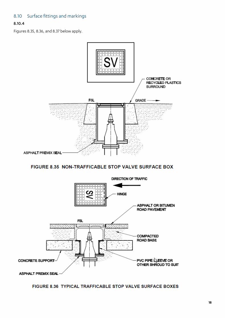
8.10 Surface fittings and markings
8.10.4
Figures 8.35, 8.36, and 8.37 below apply.

19
8.11 Appurtenance location marking
For hydrants, the publication produced by the CFA titled Identification of Street Hydrants for Firefighting Purposes applies, in conjunction with Barwon Water standard drawings listed below.
8.11.2 Marker posts and plates
Shall conform to Barwon Water standard drawing BWA-SD-G021-RA – Valve and Hydrant Identification.
8.11.3 Pavement markers
Shall conform to Barwon Water standard drawing BWA-SD-G021-RA – Valve and Hydrant Identification.
8.11.4 Kerb markers
Shall conform to Barwon Water standard drawing BWA-SD-G021-RA – Valve and Hydrant Identification.
9. Design review and drawings
9.2 Design drawings
Example drawings MRWA-W-101, MRWA-W-102A and MRWA-W-102B do not apply.
9.2.2 Composition of design drawings
Section (a) – Barwon Water does not supply a template.
9.2.4 Contents of design drawings
Parts (e), (g), and (n) do not apply.
Examples of requirements for some sections as follows –
Part (i) Works schedule
Size Type Series Length
100 mm PVC-O CL.12 2 235 mm
150 mm PVC-M CL.16 1 or 2 30 m
125 mm HDPE PE100-SDR17 100 m
20
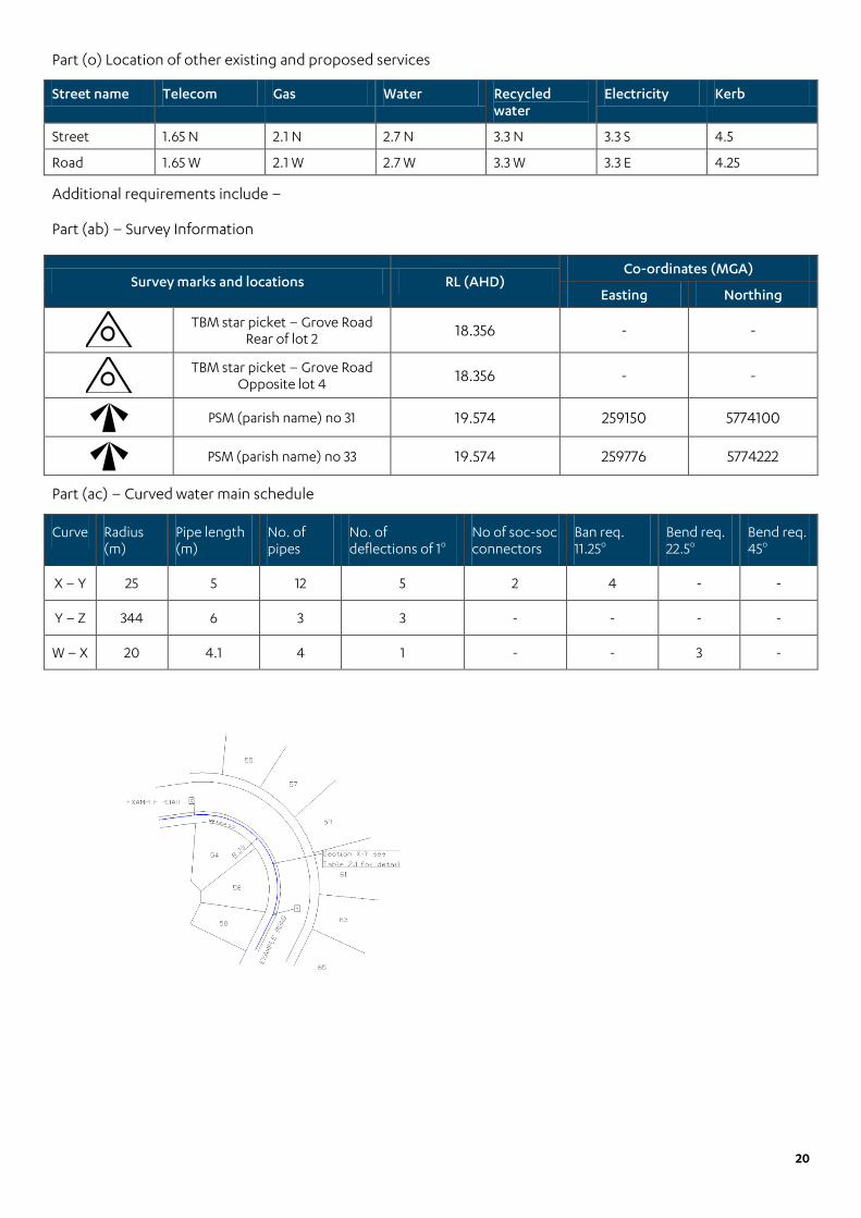
Part (o) Location of other existing and proposed services
Street name Telecom Gas Water Recycled water
Electricity Kerb
Street 1.65 N 2.1 N 2.7 N 3.3 N 3.3 S 4.5
Road 1.65 W 2.1 W 2.7 W 3.3 W 3.3 E 4.25
Additional requirements include –
Part (ab) – Survey Information
Survey marks and locations RL (AHD) Co-ordinates (MGA)
Easting Northing
TBM star picket – Grove Road
Rear of lot 2 18.356 - -
TBM star picket – Grove Road
Opposite lot 4 18.356 - -
PSM (parish name) no 31 19.574 259150 5774100
PSM (parish name) no 33 19.574 259776 5774222
Part (ac) – Curved water main schedule
Curve Radius (m)
Pipe length (m)
No. of pipes
No. of deflections of 1o
No of soc-soc connectors
Ban req. 11.25o
Bend req. 22.5o
Bend req. 45o
X – Y 25 5 12 5 2 4 - -
Y – Z 344 6 3 3 - - - -
W – X 20 4.1 4 1 - - 3 -

21
Part (ad) – Barwon Water sign off
Part (ae) – Revisions box
Line weights are to be as follows
Item Pen size
Title boundaries 0.35
Allotment boundaries 0.25
Existing services 0.25
Existing water mains 0.25
Proposed water mains 0.70
Proposed fitting 0.35
Physical features 0.25
Existing sewers 0.50
MRWA 9.2.7 Design amendments
Parts (a), (b), and (c) do not apply.
9.4 Recording of work as constructed information
This section does not apply.
Refer to Barwon Water’s Survey Manual “For Land Development”.
As constructed notes to be provided within 10 days of completing works.
ACCEPTED BY BARWON WATER LAND DEVELOPMENT COORDINATOR
DEVELOPMENT SERVICES No works shall commence prior to plans
being signed and accepted by Barwon Water

22
Part 2: Construction
11. General construction
11.1 General
Works cannot commence until design plans are signed, dated and accepted by Barwon Water.
11.2 Order of construction, testing and commissioning
Barwon Water follows the approach by City West Water and Yarra Valley Water.
Any by-pass connection required for testing purposes must be from the same water source only.
Accredited testers only are permitted to undertake testing.
Part (k) – Water services in dual pipe areas to be visually checked prior to testing and each visual check to be recorded on the test sheets, titled Recycled Water and Drinking Water Audit Checklist, provided by Barwon Water.
Part (n) – ‘As constructed’ information is to be in accordance with Barwon Water’s Survey Manual “For Land Development”.
11.4 Customer focus
11.4.1 General
Any affected land owner is to be advised 14 calendar days prior to works.
Where necessary, approval required by a land-owner is to be forwarded to Barwon Water.
11.5 Protection of property and environment
11.5.2 Disused/Redundant water mains
The developer or party causing a pipeline to be made redundant is required to purchase the pipeline in accordance with Barwon Water’s Land Development Manual.
Any works on asbestos pipe is to be undertaken using a licensed removalist. Certificate of safe disposal is to be provided upon request.
Any redundant pipes are to be included with the ‘as constructed’ notes. Details will include location and type of disconnection.
12. Products and materials
12.1 Authorised products and materials
12.1.1 General
Barwon Water’s approved product catalogues are available from its website:
http://www.barwonwater.vic.gov.au/business/products-and-standards
12.3 Transportation, handling and storage of products and materials
12.3.4 On-site storage
For all PVC pipe types, do not store in direct sunlight for a period that exceeds 6 months. This includes any time accumulated since manufacture by the manufacturer and/ or distributor. Generally, PVC pipes are to be laid within 6 months from manufacture date stamp on pipe.

23
12.6 Supply of water to the works
Only metered hydrants registered with Barwon Water are permitted to be used to extract water. Water can only be extracted from designated/ approved fireplugs. A list of these can be provided upon request.
14. Bedding for pipes
Pipe bedding to conform to Barwon Water standard drawing BWA-SD-W001 Pipelines – Trench and Backfill – Typical Details.
15.4 Valves, hydrants and other appurtenances
15.5.4.1 Installation of flanges to steel mains
The steel flanged off-take welded to the host pipe is to be pressure tested. Details of the pressure test will be supplied by Barwon Water with the “offer of conditions”.
15.7 Thrust, anchor blocks and restrained joints
Refer comments under Sections 7.9 and 19.5 of this supplement.
15.14 Scours
Scour assemblies are to conform to Barwon Water standard drawings –
BWA-SD-W010-R0 – Water Supply – Scour Valve Installation – Type A
BWA-SD-W011-R0 – Water Supply – Scour Valve Installation – Type B
17. Fill
For pipelines > DN300mm, trench fill is to conform to Barwon Water standard drawing:
BWA-SD-W001-R2 – Pipelines – Trench and Backfill – Typical Details
19.3 Compaction testing
Table 19.1 Minimum compaction of embedment, trench fill and embankments
19.3.2 Compaction testing requirements
For pipelines up to DN300mm, compaction requirements are to conform to the MRWA (Backfill) Specification No. 04-03.1
For pipelines > DN300mm, compaction is to conform to Barwon Water standard drawing –
BWA-SD-W001-R2 – Pipelines – Trench and Backfill – Typical Details
19.4 Hydrostatic pressure testing
For pipelines up to DN300mm, no change to the requirements as set.
For pipelines > DN300mm, hydrostatic pressure testing is to conform to:
Field Pressure Test - General
Testing: Field pressure-test all pipelines as soon as possible, and, unless otherwise directed or approved in writing, before joints are covered with refill.
Test pressure: As shown on the drawings
Supervision: Where specified the Principal’s Representative shall supervise the testing of each test section. Apply the test pressure for acceptance only between 8.00 a.m. and 3.00 p.m. on each working day or such other time as approved. Arrange the program to satisfy this condition.

24
Plant and materials: Supply all necessary plant labour, materials and water, and approved measuring device to determine the quantity of make up water.
Test lengths: Unless otherwise specified or approved, maximum length of a test section:
In urban areas : 300 m
In rural areas : 1000 m
Barricades: Provide sufficient barricades, safety webbing, and lights etc. for the test sections of trenching to remain part filled as specified during the field pressure tests.
Sealing: Seal the ends of each pipeline test section with gibaults blank ends supplied by the Contractor. Obtain prior written approval of the Principal’s Representative to seal a test section with a main line stop valve.
Anchors: Do not test until at least seven days after concrete thrust and anchor blocks have been poured.
Refilling: Prior to filling the pipeline with water and applying the test pressure, backfill the trench to the limits defined below or as directed.
Type of backfill (refer Drg BWA-SD-W001)
Type of pipeline Rubber ring jointed
Other than rubber ring
Pipe cover Leave top half of each joint exposed Complete
Trench backfill To within 1.0m of each joint and not less than 0.5m deep
Complete
Filling test sections: Fill the test section with water at the following maximum rates of filling. Provide a suitable flow metering arrangement to monitor the rate of filling.
Pipeline diameter Maximum filling rate
100 5 L/s
150 5 L/s
200-250 15 L/s
300-375 20 L/s
>375 0.05m/s
Constant Pressure Test (Water Loss Method)
Requirement: Use this test method for PVC, GRP, ductile iron and steel pipelines. Conduct the test generally in accordance with AS/NZS 2566.2 except as modified by this clause. Initial period: Apply the test pressure to each test section for the initial period set out below:
Pipe type Initial period
PVC and GRP 19 hours
Cement lined ductile iron:
• up to 300 metres test length • more than 300 metres test length
19 hours
43 hours
Cement lined mild steel:
• up to 300 metres test length • more than 300 metres test length
19 hours
43 hours
Two hours test: At the end of the initial period apply a two hours test irrespective of the pipe material. Apply the test pressure at the start of the two-hour period and add no water till the completion of the two hours. At that time raise the pressure to the test pressure by the addition of a measured quantity of make up water. The quantity of make up water, measured by a suitably calibrated device in the presence of the Principal’s Representative or his representative shall not exceed the allowable makeup water rate. Should the limit be exceeded, locate the fault(s) and make good to approval, and retest the test section.

25
Allowable makeup water rate: Q < 0.14LDH, where:
Q = allowable makeup water in L/hr
D = nominal diameter of the test length, in metres
L = length of test section, in km
H = average test head for section, in metres
Join up and making good: Within two days of the acceptance of the last test section of the pipeline:
Complete the "join up" of the test sections.
Make good any joint and/or pipe work that leaks or sweats.
If directed by the Principal’s Representative, retest any faulty work.
Acceptance criteria: The criteria for acceptance of a test section are:
a) The makeup water rate does not exceed the allowable limit. b) There is no visible leak/weep or failure of any pipe, fitting valve, joint, anchorage or other component of
the test section.
The criterion for acceptance of each "join up" is (b) of this Sub Clause.
Constant Pressure Test (Water Loss Method) for Visco-Elastic Pipes
Requirement: Use this test method for PE, PP and ABS pipelines. Conduct the test generally in accordance with AS/NZS 2566.2 except as modified by this clause.
Procedure:
Apply the test pressure to each test section.
Shut off the section and allow the pressure to settle for 12 hours.
Reapply the test pressure hourly over five hours by adding measured quantities of makeup water.
Measure and record the volume of makeup water required between hour 2 and hour 3 as V1.
Measure and record the volume of makeup water required between hour 4 and hour 5 as V2.
Allowable makeup water rate: V2 < (0.55V1 + 0.14LDH), where:
V2 = allowable makeup water in L/hr
D = nominal diameter of the test length, in metres
L = length of test section, in km
H = average test head for section, in metres
Join up and making good: Within two days of the acceptance of the last test section of the pipeline:
Complete the "join up" of the test sections.
Make good any joint and/or pipe work that leaks or sweats.
If directed by the Principal’s Representative, retest any faulty work.
Acceptance criteria: The criteria for acceptance of a test section are:
a) The makeup water rate does not exceed the allowable limit. b) There is no visible leak/weep or failure of any pipe, fitting valve, joint, anchorage or other component of
the test section. The criterion for acceptance of each "join up" is (b) of this Sub Clause.

26
19.4.3 Property Services
In addition, the following procedure also applies for dual pipe areas and assets provided by the developer:
1. Close any cross connection between drinking and recycled water systems. 2. Charge drinking water system with potable water. 3. Have each gate valve on the drinking water system physically checked to ensure it is OPEN. 4. Open, successively, all hydrants/fire plug and scours on drinking water system. Check that all outlets run
with water. 5. Check that all hydrants/fire plug covers, hydrants/fire plugs/valve surrounds and marker posts, reflective
pavement markers are marked in accordance with this Supplement and the MRWA Edition of the WSAA Water Supply Code.
6. Check that all property services and ball valve handles on the drinking water system meet the requirements of this Supplement and the MRWA Edition of the WSAA Water Supply Code and are not coloured purple.
7. Check that all property service pipes and ball valve handles on recycled water system are coloured purple. 8. Drain the non-drinking water system by successively opening all hydrants/fire plug and scours on the
recycled water system. 9. Open, successively, all termination ball valves on the drinking water property services. Check that all
outlets run with water. 10. If no water is detected through the termination ball valves on the drinking water system ensure the
property service is connected to the drinking water system and/or main tap ball valve is in open position. 11. Open, successively, all termination ball valves on the recycled water property service line. All outlets
should run dry after a short time. 12. If any of the tests prove to be unsatisfactory, detect and rectify the fault, and re-test. 13. Continue to rectify and re-test until a satisfactory test result is achieved. 14. Recharge recycled water supply system. 15. Repeat process for recycled water system.
During pressure testing of the reticulation mains, the TPFNR Ferrule Cock or electro fusion tapping saddle (with integral cutter and service isolation valve) must be open for each service connection. For each property service, the ball valve at the property shall be closed. The appropriate ball valves at each property need to be temporarily opened to allow water to flow through the service. This will ensure any trapped air can escape, and to check that service connections are to the correct water supply main (drinking or non-drinking).
The consultant is required to submit an ITP for Barwon Water approval prior to works beginning. The ITP will establish hold and witness points during the installation and commissioning of non-drinking water mains, including non-drinking water main-to-meter services. The ITP needs to specifically address commissioning procedures to identify any possible cross-contamination (refer to EPA Victoria Draft Guidelines for Dual Pipe Water Recycling Schemes – Health and Environmental Risk Management). This system integrity inspection should be conducted as part of the commissioning of the dual water supply system by Barwon Water’s Quality Auditors, the consultant and the contractor. The system integrity inspection is designed to eliminate the potential for cross contamination caused when a drinking water service is connected to a non-drinking water main.
The consultant and the contractor must coordinate the timing of the commissioning process with Barwon Water, and only proceed with the commissioning process with a Barwon Water Quality Auditor present. Failure to do so will result in the works being rejected and the testing will need to be repeated. If a Barwon Water Auditor is not available at the time the contractor wishes to conduct the commissioning, this will not be accepted as a reason for not having the commissioning witnessed. Barwon Water will bear no cost for the commissioning and/or repeating of the commissioning testing, to comply with this requirement.

27
19.5 Block testing dual water supply systems for connectivity
Where non-restrained joint pipeline systems are used, separate thrust /anchor blocks shall be provided except where common thrust /anchor blocks are required due to site constraints, in which case the thrust /anchor blocks shall be designed for all design force combinations. Elastomeric seal joints shall not be encased by concrete.
As part of the Inspection and Test Plan (ITP), Barwon Water requires the constructor to include hold and witness points for the installation of thrust /anchor blocks. These are to be accepted by the consulting engineer or accredited tester.
The need for thrust /anchor restraint can be reduced by the use of PE pipe material. Pipeline anchorage for PE pipes is detailed in the Polyethylene Pipeline Code WSA 01-2001 Section 2.11.4, which notes:
• Electrofusion joints, butt weld joints and compression fittings that comply with AS/NZS 4129 can develop the full axial strength of the pipe, and in buried applications do not require thrust blocks to resist internal pressure forces at bends, tees, reducers, offsets, dead ends, and so on.
19.7 Water quality testing
Testing to conform to Barwon Water’s Water Quality Guidance for the Commissioning of Assets in Contact with Potable Water. A copy can be provided upon request.
20. Disinfection
Disinfection to conform to Barwon Water’s Water Quality Guidance for the Commissioning of Assets in Contact with Potable Water. A copy can be provided upon request.
22 Connections to existing water mains
22.3 Inserted tee connections
22.3.1 Shutdown of existing water mains
Non-Barwon Water personnel are not permitted to operate any part of the water system.
Barwon Water requires a minimum 10 days notice for connection to live water mains or for any tapping under pressure. Further requirements can be found in Barwon Water’s Land Development Manual.
22.3.3 Re-charging the shutdown water main
Non-Barwon Water personnel are not permitted to operate any part of the water system.
24 Work as constructed details
This section does not apply.
Refer to Barwon Water’s Survey Manual “For Land Development”
As constructed notes are to be submitted within 10 working days after completion of works.

28
Drawings
MRWA-W-100 Water Supply Symbol Library
Barwon Water, on occasion, will permit or require the use of temporary stop valves. Those normally permitted are known as infra-stops (although others may be used subject to approval), and should these be required, Barwon Water will provide information on how these are represented on the design at time of design submissions, or prior, upon request.
MRWA-W-101 Design Template with Example Design Locality Plan and Notes
Not used by Barwon Water.
MRWA-W-1-102A Example Design Detail Plan
Not used by Barwon Water.
MRWA-W-103 General Pipeline System Requirements
Table 4 – For PE pipe range <DN125PE – mechanical compression or push fit joints not permitted.
Minimum pipe size permitted is DN50mm (63mm OD PE).
MRWA-W105 Distribution Main Divide Valve & Bypass Arrangements for >DN375 Mains
Refer to comments made in this supplement under Section 8.2 when using this drawing.
MRWA-W106 Connection of >= DN100 Offtakes to Existing Mains
A fire plug is always required immediately after a stop valve at any offtake to another water main.
MRWA-W-107 Connection of Off-takes and Services to >= DN100 Mains
Applies to sizes DN50mm (63MM OD PE) and above.
Detail B: PE Main Mechanical Tapping Band – not permitted.
MRWA-W-108 Polyethylene Reticulation in Residential Cul-de-sacs
Not used by Barwon Water.
MRWA-W-110 Residential Property Service Arrangements
Not used by Barwon Water.
Pre-tapped connectors not permitted.
Tappings to be in accordance with Barwon Water standard drawings 70112, 70200, and 70201.
MRWA-W-111 Residential Property Service Connection Details
Not used by Barwon Water.
Pre-tapped connectors not permitted.
Detail F – separate property service ducts are required for each service.
Tappings to be in accordance with Barwon Water standard drawings 70112, 70200, and 70201.

29
MRWA-W-201 Pipeline Embedment and Trench Backfill
The following applies for pipelines up to DN300mm.
Class 4 crushed rock, recycled glass, crushed concrete, and scoria not permitted.
Class 3 crushed rock may be permitted within the backfill zone only if approved by the relevant road authority. Such approval is to be presented to Barwon Water prior to its use.
For pipelines > DN300mm use Barwon Water standard drawing –
BWA-SD-W001 Pipelines – Trench and Backfill – Typical Details
MRWA-W-202 Pipe Trench Details
Cover requirements referred to under drawing MRWA-W-202 do not apply.
Refer to comments made in this supplement under Section 7.4.2 when using this drawing.
MRWA-W-212 Curves and Deflections (Horizontal and Vertical)
Refer to comments under sections 5.4.14 and 9 of this supplement.
MRWA-W-301 Valve and Hydrant Marking Details
Marker posts for stop valves only required for those that are designated “zone” valves.
Shall conform to Barwon Water standard drawing BWA-SD-G021-RA – Valve and Hydrant Identification and CFA publication Identification of Street Hydrants for Firefighting Purposes.
MRWA-W-302 Valve Surface Fittings Trafficable and Non-trafficable Areas
Non trafficable: Non-drinking water (round) not permitted.
MRWA-W-303 Hydrant and Washout Surface Arrangements
Detail D – All in one hydrant not used.
Hydrants on water mains >DN300 are to conform to Barwon Water standard drawing –
BWA-SD-W005-R0 – Isolating Hydrant Details
MRWA-W-304 Hydrant and Air Valve Arrangements
This drawing not used by Barwon Water.
Air valves are to conform to Barwon Water standard drawings –
BWA-SD-W020-R0 – Water Supply – Air Valve Details – Type A and B – Non-trafficable
BWA-SD-W021-R1 – Water Supply – Air Valve Details – Type C and D
BWA-SD-W022-R0 – Water Supply – Air Valve Details – Type E and F – Non-trafficable
MRWA-W-305 Hydrant and Air Valve Fitting Details
This drawing not used by Barwon Water.
Air valves are to conform to Barwon Water standard drawings –
BWA-SD-W020-R0 – Water Supply – Air Valve Details – Type A and B – Non-trafficable
BWA-SD-W021-R1 – Water Supply – Air Valve Details – Type C and D
BWA-SD-W022-R0 – Water Supply – Air Valve Details – Type E and F – Non-trafficable

30
MRWA-W-307 Scour Arrangements for >= DN300 Mains
This drawing not used by Barwon Water.
Scour assemblies are to conform to Barwon Water standard drawings –
BWA-SD-W010-R0 – Water Supply – Scour Valve Installation – Type A
BWA-SD-W011-R0 – Water Supply – Scour Valve Installation – Type B
500 Series – Water Metering
Drawing Number 1 – 20-25mm General Water Service (Wet Tapping) Low Hazard Resident
A pressure limiting valve with dual check valve is required after the water meter. Maximum set pressure at 500kPa.
A male thread only ball valve is permitted.
Tapping example (ball valve) not permitted.
Drawing Number 4 – 32-50mm General Water Service Low Hazard Residential/ Commercial/ Industrial Typical Arrangement
An assembly support bracket is required immediately after the water meter.
Drawing Number 7 – 80mm+ General Water Service Medium/ High Hazard Residential/ Commercial/ Industrial Typical Arrangement
Water meter height from finished surface level to be between 300mm (minimum) and 600mm (maximum).
Drawing Number 8 – 25-50mm Fire Hose Reel/ Sprinkler and General Service Typical Arrangement
A gate/ ball valve (same as item no. 3) is required on the fire hose reel service immediately after the split between the fire hose reel service and the general water service.
Drawing Number 9 – 80mm+ Fire Hydrant/ Hose Reels with Detector Check Valve Typical Arrangement
A test ferrule is to be placed after the by-pass water meter.
Drawing Number 10 – 80mm+ Fire and General Service Combined Residential/ Commercial/ Industrial Typical Arrangement
This configuration is not approved for use by Barwon Water.
Drawing Number 11 – 80mm Fire and General Service Separated Fire and General Services After Water Meter Typical Arrangement
The general water service is to be separated below ground and prior to the vertical bend (prior to the isolating valve – item no. 3).
Drawing Number 14 – Booster Connection around Meter Fire Sprinkler Supply Typical Arrangement
A test ferrule is required after the magnetic flow water meter.
Drawing Number 15 – Booster Connection around Meter Fire Hydrant Supply Typical Arrangement
A test ferrule is to be placed after the by-pass water meter.
Drawing Number 16 Interconnected Fire and General Services Single Water Main Supply from Both Directions Typical Arrangement
A test ferrule is to be placed after the by-pass water meter.
Drawing Number 18 – Tapping Configurations Typical Arrangement
Tapping under pressure up to 50mm (Ball Valve) not permitted.

31
Barwon Water standard drawings (included with this supplement) Drawing number Title
70112 Pre-tapping installation
70200 Typical cross section – recycled water tapping
70201 Typical plan section – recycled water tapping
70202 Potable and Non-potable water cross connection
70203 Drinking and recycled water cross connection telemetry wiring and architecture diagram
Barwon Water standard drawings (not included) (available upon request) Drawing number Title
BWA-SD-G021-RA Valve and Hydrant Identification
BWA-SD-W001-R2 Pipelines – Trench and Backfill – Typical Details
BWA-SD-W002-R0 Thrust and Anchor Block – Typical Details
BWA-SD-W003-R0 Blank End – Thrust Block – Typical Details
BWA-SD-W005-R0 Isolating Hydrant Details
BWA-SD-W010-R0 Water Supply – Scour Valve Installation – Type A
BWA-SD-W011-R0 Water Supply – Scour Valve Installation – Type B
BWA-SD-W012-R0 Water Supply – Line Valve with Scour Bypass
BWA-SD-W020-R0 Water Supply – Air Valve Details – Type A and B – Non-trafficable
BWA-SD-W021-R1 Water Supply – Air Valve Details – Type C and D
BWA-SD-W022-R0 Water Supply – Air Valve Details – Type E and F – Non-trafficable

Pre tapping installation
GSDM_10496
Typical cross sectionnot to scale
500 mm
200 mm
Detector tape
Ball valve
Service
Conduit
Main ferrule (to be left open)
Tapping saddle
Water main
PVC access pipe
Cover
Kerb marked with ‘W’ for water to indicate where 50 mm conduit passes under the road
‘W’ ‘W’
1. All lots are to be tapped using a tapping saddle and pressure ferrule.
2. A minimum size service (ie. 20 mm copper, 25 mm PE) is then to be extended to a point 500 mm within the property.
3. Service pipe between main ferrule and ball valve to be a continuous length (ie. no joins)
4. Service to be type ‘B’ copper or class 12 type 50 PE.
5. In the case of PE or any other non-metallic service being installed, a copper trace wire is to be incorporated.
6. A buried ball valve is to be placed at the end of the service.
7. Detector tape is to be run to surface level.
8. Ball valve to be in accordance with Australian standards (ie. stamped ‘W’) brass fitting with stainless steel ball.
Pro
pert
y bo
unda
ry
Standard drawing 70112

GSDM_10835_70200
Typical cross section - Recycled Water Tappingnot to scale
Standard drawing 70200
500 mm
600 mm max
200 mm
Recycled water detector tape
Purple coatedball valve
Service
Conduit(separate to water)
Main ferrule (to be left open)
Tapping saddle
Recycled water main
PVC access pipe
Cover
Kerb marked with ‘NDW’ or ‘RW’ for water to indicate where 50 mm conduit passes under the road
‘NDW’ or ‘RW’ ‘NDW’ or ‘RW’
1. All lots are to be tapped using a tapping saddle and pressure ferrule.
2. A minimum size service (25 mm PE) is then to be extended to a point 500 mm within the property.
3. Service pipe between main ferrule and ball valve to be a continuous length of purple pipe. (ie. no joins)
4. In the case of PE or any other non-metallic service being installed, a copper trace wire is to be incorporated.
5. A buried purple ball valve (male iron) is to be placed at the end of the service with purple bucket protector.
6. Recycled water detector tape is to be run to surface level.
7. Ball valve to be in accordance with Australian standards (ie. stamped ‘NDW’ or ‘RW’) brass fitting with stainless steel ball.
Pro
pert
y bo
unda
ry

GSDM_10838_70201
Typical plan section - Recycled water tappingnot to scale
1. All lots are to be tapped using a tapping saddle and pressure ferrule.
2. A minimum size service (25 mm PE) is then to be extended to a point 500 mm within the property.
3. Service pipe between main ferrule and ball valve to be a continuous length of purple pipe (ie. no joins).
4. In the case of PE or any other non-metallic service being installed, a copper trace wire is to be incorporated.
5. A buried purple ball valve (male iron) is to be placed at the end of the service with purple bucket.
6. Recycled water detector tape is to be run to surface level.
7. Ball valve to be in accordance with Australian standards (ie. stamped ‘W’) brass fitting with stainless steel ball.
Note: This drawing is to be read in conjunction with Barwon Water’s standard drawing typical cross section - recycled water tapping.
Pro
pert
y bo
unda
ry
No
n-dr
inki
ng w
ater
mai
n
Dri
nkin
g w
ater
mai
n
Note: Conduit parallel at 300 mm spacing
300 mm
Kerb
Lin
e
Kerb
Lin
e
Footway Footway
Other services
Carriageway
300 mm
700 mm
DN 25 drinking water and
DN 25 non-drinking water property services
Service ductkerb marking
Pro
pert
y bo
unda
ry
Standard drawing 70201
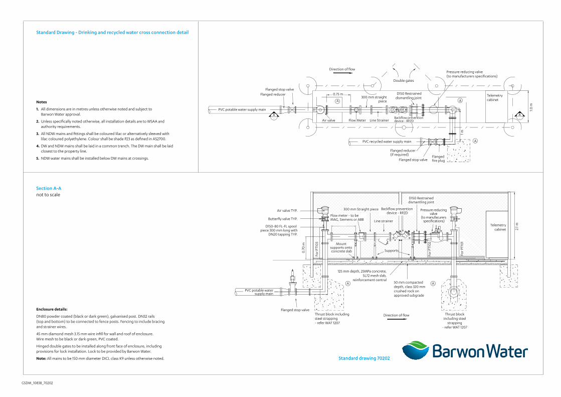
Backflow preventiondevice - RPZDFlow Meter Line Strainer
750
2.1 m
Air valve
0.75 m
1.0 m
Direction of flow
300 mm straightpiece
Double gates
Flanged stop valve
1 m
PVC potable water supply main
PVC recycled water supply main
Flanged reducer(if required)
Flanged stop valve
Air valve TYP.
Butterfly valve TYP.
D150-80 FL-FL spool piece 300 mm long with
DN20 tapping TYP.
Flanged fire plug
Flanged reducer
0.70
m
D150 Restrained dismantling joint
Pressure reducing valve (to manufacturers specifications)
Telemetry cabinet
Telemetry cabinet
Thrust block including steel
strapping - refer WAT 1207
125 mm depth, 25MPa concrete, SL72 mesh slab,
reinforcement central
Thrust block including steel strapping - refer WAT 1207
Flanged stop valve
PVC potable water supply main
50 mm compacted depth, class 320 mm crushed rock on approved subgrade
Direction of flow
A
A
A
AA
7
300 mm Straight piece
Flow meter - to be MAG, Siemens or ABB
Supports
Backflow prevention device - RPZD
D150 Restraineddismantling joint
Pressure reducing valve
(to manufacurers specifications)
For P
T10
1
Line strainer
Mount supports onto concrete slab
For P
T10
2
For P
T10
3
A.
A.
GSDM_10838_70202
Notes
1. All dimensions are in metres unless otherwise noted and subject to Barwon Water approval.
2. Unless specifically noted otherwise, all installation details are to WSAA and authority requirements.
3. All NDW mains and fittings shall be coloured lilac or alternatively sleeved with lilac coloured polyethylene. Colour shall be shade P23 as defined in AS2700.
4. DW and NDW mains shall be laid in a common trench. The DW main shall be laid closest to the property line.
5. NDW water mains shall be installed below DW mains at crossings.
Enclosure details:
DN80 powder coated (black or dark green), galvanised post. DN32 rails (top and bottom) to be connected to fence posts. Fencing to include bracing and strainer wires.
45 mm diamond mesh 3.15 mm wire infill for wall and roof of enclosure. Wire mesh to be black or dark green, PVC coated.
Hinged double gates to be installed along front face of enclosure, including provisions for lock installation. Lock to be provided by Barwon Water.
Note: All mains to be 150 mm diameter DICL class K9 unless otherwise noted.
Section A-Anot to scale
Standard Drawing - Drinking and recycled water cross connection detail
Standard drawing 70202

GSDM_10838_70203
Standard Drawing - Drinking and recycled water cross connection telemetry wiring and architecture diagramnot to scale
Notes:
1. Miniature circuit breakers shall be NHP/TERASAKI dint type, minimum 6KA
2. Refer drawing 3004735-C012 for panel details
3. Fused main connection point and consumer sub-mains will be supplied and installed by others. Powercor will supply and install fuse in the connection pit or pillar and terminate supply side cables
Note: This drawing is to be read in conjunction with drinking and recycled water cross connection detail and subject to Barwon Water approval.
Legend Switchboard terminal
Instrumentation terminal (SAK-R)
RTU or PLC I/O terminal
Fuse terminal
IO-3
P2
P1
PC-1
Spar
e
Spar
e
1AI14.2
2AI14.3
3AI14.4
4AI14.5
5OV
6+24V14
7AO14.6
8OV
9E
10D14.1
11D14.2
12D14.3
13D14.4
14COMM
15DO14.9
16DO14.10
(-)
(+)
(-)
(+)
#
#(-)
(+)
E
123456789
+24V AUX SUPPLY OUTPUT
0V AUX SUPPLY OUTPUT
0V TO/FROM BATTERY
+12V TO RADIO
OV TO RADIO
+12V INPUT SUPPLY
0V INPUT SUPPLY
EARTH
+12V TO/FROM BATTERYB+B-
VR+VR-V+V-
EARTH
B+B-VR+VR-V+V-
12V DC
230VAC
12V DC
24V DC
FLOW0-120 L/S
GEM DS SD4 DB-9RG213
- +BAT2-BAT2+
- +BAT1-BAT1+
F AN
AFNF
123
456
CB1FNF
F82.5A
17DO14.11
18DO14.12
19COMM
20
AI14.2
AI14.3
AI14.4
AI14.5
+24V14.1
AO14.6
OV
D14.1
D14.2
D14.3
D14.4
COMM
DO14.9
DO14.10
DO14.11
DO14.12
COMM
E
AI14.2
24V141.1.1
AI14.3
24V14.1.2
14.4
0V14.1
F380mA
+24V14.1.4
Plin
e
B-2a B+2a
F62AB-2
B+2
F480mA
F580mA
(-)
(+)-1.3
0V14.5
FX80mA
Kingfisher plus+ RTUBA-4 4 Slot backplane
Vegabar 142 bar 14x1GA1GP11/2” BSP (Inner 1/4”)
PRV upstream pressure 0-16 bar
PRV downstream
pressure 0-16 bar
ABB “Watermaster” electromagnetic flow meter
Powerbox DC-DCconverter (or equivalent)
Enclosure door 1 magnetic limit switch
(range > 25mm)
Enclosure door 1 magnetic limit switch
(range > 25mm)
Flow totaliser
Intrusion status
SL9 Connector wiring details (located on BA4 rack)
Batteries 2 x PS1265 12V, 6.5 AH provide minimum 24 hours backup for normal operation
SDO4MD-CES-NNSNNBAND C (450-520 MHZ)
“TNC”type male
“N”type male
“N”type male
Lightning arrestorpolyphaser
IS-B50LN-C2
Power supply Allen Bradley 1606-XLP90B
12-15V dc, Pmax 90WTransient filter
TCA TC-10A 240
Earth electrode
230 V single phase 2A unmetered supply
from powercore
Fused mains connection pit
CR pillar
By others - note 3
Cabinet earth stud/earth bar
To cabinet earth stud/earth bar
Main switch 2A MCB (Class D trip curve)
230 V power supply section
YAGI antenna (9 element) type YB9-61
H: 6.5 m (O: TBA DEG) Direction to be confirmed
10-3 (4xAI, 1xAO, 4xDI, 4xDO)Rack: 1, Slot: 2, Add: 14
PC-1 (Processor) Rack: 1, Slot: 1, Add: 13
PT101
PT102
FT104
PT103
Cross Connection PRV RTV
Standard drawing 70203