support the growth of ultrasonic motors. create innovative ... · ultrasonic motor product...
TRANSCRIPT

Support the Growth of Ultrasonic Motors.Create Innovative Actuators.
ULTRASONIC MOTOR CATALOG

ULTRASONIC MOTOR
CONTENTS
About Ultrasonic Motor
Product Introduction
For General Environment Motor
Nonmagnetic Compatibility Motor
USR Series Driver
Connection Diagram of the basic
Configuration of the Connection Terminals
External dimensions
Specification
Q&A / Support / Inquiries
P03
P04
P07
P09
P11
P12
P13
P15
P18
High Quality, Compact, Quiet, High Torque Motor
Motor for High Magnetic Field Environment is Ultrasonic Motor made by SHINSEI
Product Lineup
※1 Notation is a reference value: Rotation Speed × Torque, it does not indicate Electric Power.
※2 Nonmagnetic Compatibility Motor and Cable are guaranteed to operate in 3T Magnetic Field Environment (Driver is Not Nonmagnetic Compatible)
For General Environment
Motor
For Built-in Caseless Model
Basic Model
Basic Model
With Encoder Model
With Encoder Model
Nonmagnetic Compatibility Motor
Model / Product Number
Rotation Speed(rpm) Torque(N・m/Kg・cm) Power(W) Avai lable Dr ivers(24V/12V)
Rating Maximum Rating Maximum(by Maximum Load)
D6030 D6060 D6060E D6060SRating Maximum Holding power
●
●
●
●
●
USR30-B3/USR30-B4 250 300 0.05/0.5 0.1/1.0 0.1/1.0 1.3 2.5
USR30-S3/USR30-S4 250 300 0.05/0.5 0.1/1.0 0.1/1.0 1.3 2.5
USR60-S3/USR60-S4 100 150 0.5/5.0 1.0/10.0 1.0/10.0 5.0 10.0
USR30-E3/E3T 250 300 0.05/0.5 0.1/1.0 0.1/1.0 1.3 2.5
USR60-E3/E3T 100 150 0.5/5.0 1.0/10.0 1.0/10.0 5.0 10.0
USR30-S3N/USR30-S4N 200 250 0.05/0.5 0.1/1.0 0.1/1.0 1.0 2.0
USR60-S3N/USR60-S4N 100 150 0.5/5.0 1.0/10.0 1.0/10.0 5.0 10.0
USR30-E3N/E3NT 200 250 0.05/0.5 0.1/1.0 0.1/1.0 1.0 2.0
USR60-E3N/E3NT 100 150 0.5/5.0 1.0/10.0 1.0/10.0 5.0 10.0
●
●
●
●
●
●
●
●
●
●
●
●
●
●
●
●
●
●
●
●
●
●
ULTRASONIC MOTOR
03
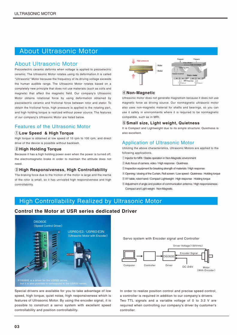
About Ultrasonic MotorPiezoelectric ceramic deforms when voltage is applied to piezoelectric
ceramic. The Ultrasonic Motor rotates using its deformation.It is called
"Ultrasonic" Motor because the frequency of its driving voltage exceeds
the human audible range. The Ultrasonic Motor rotates based on a
completely new principle that does not use materials (such as coils and
magnets) that affect the magnetic field. Our company's Ultrasonic
Motor obtains rotational force by using deformation obtained by
piezoelectric ceramic and frictional force between rotor and stator. To
obtain the frictional force, high pressure is applied to the rotating part,
and high holding torque is realized without power source. The features
of our company's Ultrasonic Motor are listed below.
Features of the Ultrasonic Motor①Low Speed & High TorqueHigh torque is obtained at low speed of 10 rpm to 100 rpm, and direct
drive of the device is possible without backlash.
②High Holding TorqueBecause it has a high holding power even when the power is turned off,
the electromagnetic brake in order to maintain the attitude does not
need.
③High Responsiveness, High ControllabilityThe braking force due to the friction of the motor is large and the inertia
of the rotor is small, so it has unrivaled high responsiveness and high
controllability.
④Non-MagneticUltrasonic motor does not generate magnetism because it does not use
magnetic force as driving source. Our nonmagnetic ultrasonic motor
also uses non-magnetic material for shafts and bearings, so you can
use it safely in environments where it is required to be nonmagnetic
compatible, such as in MRI.
⑤Small size, Light weight, QuietnessIt is Compact and Lightweight due to its simple structure. Quietness is
also excellent.
Application of Ultrasonic MotorUtilizing the above characteristics, Ultrasonic Motors are applied to the
following applications.
① Injector for MRI / Stable operation in Non-Magnetic environment
②Auto focus of camera, video / High response · Quietness
③ Inspection equipment for breaking strength of materials / High response
④Opening / closing of the Curtain, Roll screen / Low speed · Quietness · Holding torque
⑤XY table, robot hand / Compact Lightweight · High response · Holding torque
⑥Adjustment of angle and position of communication antenna / High responsiveness ·
Compact and Light weight · Non-Magnetic.
Control the Motor at USR series dedicated Driver
Special drivers are available for you to take advantage of low
speed, high torque, quiet noise, high responsiveness which is
features of Ultrasonic Motor. By using the encoder signal, it is
possible to construct a servo system with excellent speed
controllability and position controllability.
In order to realize position control and precise speed control,
a controller is required in addition to our company's drivers.
Two TTL signals and a variable voltage of 0 to 3.2 V are
required when controlling our company's driver by customer's
controller.
D6060E(Speed Control Driver)
USR60-E3/USR60-E3N(Ultrasonic Motor with Encoder)
※D6060E is a driver for the USR60 series, but it is also possible to correspond to the USR30 series.
Servo system with Encoder signal and Controller
Computer
Driver Voltage(130Vrms)
Encoder Signal
DC電源
D6060E
Motor(With Encoder)
DC 24VDriverController
About Ultrasonic Motor
High Controllability Realized by Ultrasonic Motor

ULTRASONIC MOTOR
04
Product Introduction/For General Environment Motor
For Built-in Caseless Model
USR30-B series is a built - in type compact Ultrasonic Motor whose diameter is 30mm. Maximum Torque is 0.1 [Nm], Maximum Speed is 300
[rpm]. USR30-B3 is a single - shaft type with output shaft only, USR30-B4 is double - shaft type with sensor mountable.
■Selectable Driver
D6030 D6060E D6060S
USR30-B3/USR30-B4
■T-N Characteristic
150
100
0
50
0.02 0.1Torque (N-m)
0.04 0.06 0.08
300
250
200
(rpm)
Sp
ee
d
Normal use range
Short-time use range
※Normal use range:Normal use range: Motor speed range below the rated torque / Short-time use range:Short-time use range: Motor speed range from rated to maximum torque
USR30-S series is a basic model that is highly rugged because it is housed in a case, allowing cable attachment and detachment by connectors.
Maximum Torque is 0.1 [Nm], Maximum Speed is 300 [rpm]. USR30-S3 is a single - shaft type, USR30-S4 is double - shaft type.
USR30-S3/USR30-S4
Basic Model
■Selectable Driver
D6030 D6060E D6060S
■T-N Characteristic
150
100
0
50
0.02 0.1Torque (N-m)
0.04 0.06 0.08
300
250
200
(rpm)
Sp
ee
d
Normal use range
Short-time use range

ULTRASONIC MOTOR
Product Introduction/For General Environment Motor
※Normal use range:Normal use range: Motor speed range below the rated torque / Short-time use range:Short-time use range: Motor speed range from rated to maximum torque
05
USR60-S series is a basic type model that is highly rugged because it is housed in a case,allowing cable attachment and detachment by connec-tors. Maximum Torque is 1.0 [Nm], MaximumSpeed is 150 [rpm]. USR60-S3 is a single - shaft type,USR60-S4 is double - shaft type.
■Selectable Driver
D6060 D6060E D6060S
USR60-S3/USR60-S4
USR30-E series has an incremental type rotary encoder. Maximum Torque is 0.1 [Nm], Maximum Speed is 300 [rpm]. Resolution of encoders of USR30-E3, E3T, E3R are 500 [P/R], 1,000 [P/R]. From the encoder, three signals of phase A, phase B, and Z (I) are output at TTL level.
USR30-E3/E3T
With Encoder Model
■Selectable Driver
D6030 D6060E D6060S
■T-N CharacteristicS
pe
ed
(rpm)
8060
0
4020
0.2 1.0Torque (N-m)0.4 0.6 0.8
160140120100
Normal use range
Short-time use range
Basic Model
■T-N Characteristic
150
100
0
50
0.02 0.1Torque (N-m)
0.04 0.06 0.08
300
250
200
(rpm)
Sp
ee
d
Normal use range
Short-time use range
ULTRASONIC MOTOR
Product Introduction/For General Environment Motor
※Normal use range:Normal use range: Motor speed range below the rated torque / Short-time use range:Short-time use range: Motor speed range from rated to maximum torque
06
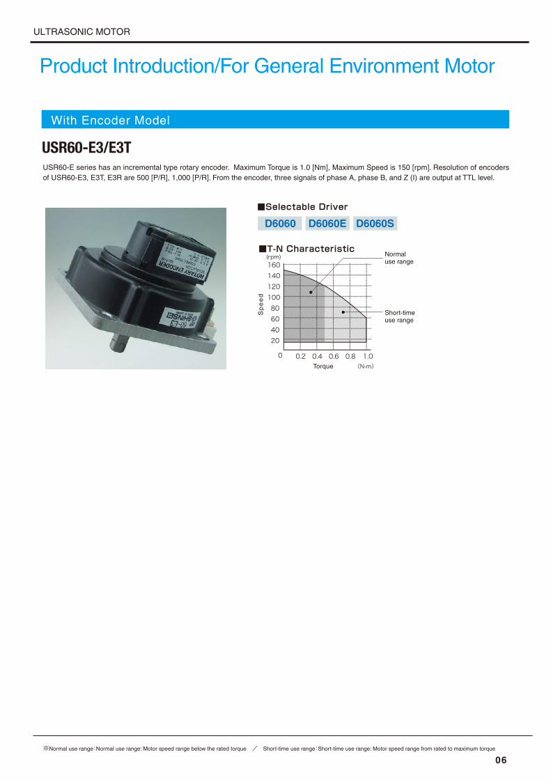
USR60-E series has an incremental type rotary encoder. Maximum Torque is 1.0 [Nm], Maximum Speed is 150 [rpm]. Resolution of encoders of USR60-E3, E3T, E3R are 500 [P/R], 1,000 [P/R]. From the encoder, three signals of phase A, phase B, and Z (I) are output at TTL level.
■Selectable Driver
D6060 D6060E D6060S
USR60-E3/E3T
With Encoder Model
■T-N CharacteristicS
pe
ed
(rpm)
8060
0
4020
0.2 1.0Torque (N-m)0.4 0.6 0.8
160140120100
Normal use range
Short-time use range
ULTRASONIC MOTOR
※Normal use range:Normal use range: Motor speed range below the rated torque / Short-time use range:Short-time use range: Motor speed range from rated to maximum torque
07
Product Introduction/Nonmagnetic Compatibility Motor
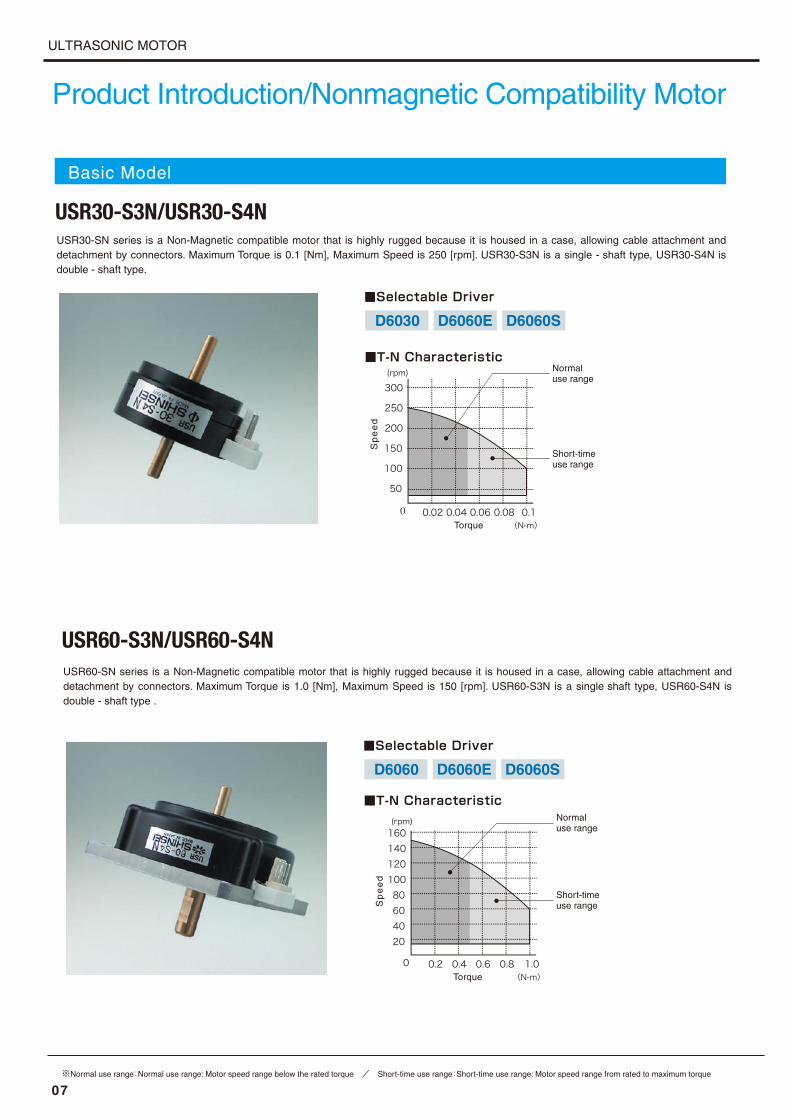
USR30-SN series is a Non-Magnetic compatible motor that is highly rugged because it is housed in a case, allowing cable attachment and detachment by connectors. Maximum Torque is 0.1 [Nm], Maximum Speed is 250 [rpm]. USR30-S3N is a single - shaft type, USR30-S4N is double - shaft type.
■Selectable Driver
D6030 D6060E D6060S
USR30-S3N/USR30-S4N
USR60-SN series is a Non-Magnetic compatible motor that is highly rugged because it is housed in a case, allowing cable attachment and detachment by connectors. Maximum Torque is 1.0 [Nm], Maximum Speed is 150 [rpm]. USR60-S3N is a single shaft type, USR60-S4N is double - shaft type .
USR60-S3N/USR60-S4N
■Selectable Driver
D6060 D6060E D6060S
Basic Model
■T-N Characteristic
0 0.02 0.1Torque (N-m)0.04 0.06 0.08
150
100
50
300
250
200
(rpm) Normal use range
Short-time use range
Sp
ee
d
■T-N Characteristic
Sp
ee
d
(rpm)
8060
0
4020
0.2 1.0Torque (N-m)0.4 0.6 0.8
160140120100
Normal use range
Short-time use range

ULTRASONIC MOTOR
※Normal use range:Normal use range: Motor speed range below the rated torque / Short-time use range:Short-time use range: Motor speed range from rated to maximum torque
Product Introduction/Nonmagnetic Compatibility Motor
08
USR30-EN series is a Non-Magnetic compatible motor that has an incremental type rotary encoder. Maximum Torque is 0.1 [Nm], Maximum Speed is 250 [rpm]. Resolution of encoders of USR30-E3N, E3NT, E3NR are 500 [P/R], 1,000 [P/R]. From the encoder, three signals of phase A, phase B, and Z (I) are output at TTL level.
■Selectable Driver
D6030 D6060E D6060S
USR30-E3N/E3NT
With Encoder Model
USR60-EN series is a Non-Magnetic compatible motor that has an incremental type rotary encoder. Maximum Torque is 1.0 [Nm], Maximum Speed is 150 [rpm]. Resolution of encoders of USR60-E3N, E3NT, E3NR are 500 [P/R], 1,000 [P/R]. From the encoder, three signals of phase A, phase B, and Z (I) are output at TTL level.
USR60-E3N/E3NT
■Selectable Driver
D6060 D6060E D6060S
■T-N Characteristic
0 0.02 0.1Torque (N-m)0.04 0.06 0.08
150
100
50
300
250
200
(rpm) Normal use range
Short-time use range
Sp
ee
d
■T-N Characteristic
Sp
ee
d
(rpm)
8060
0
4020
0.2 1.0Torque (N-m)0.4 0.6 0.8
160140120100
Normal use range
Short-time use range

ULTRASONIC MOTOR
09
Product Introduction/Motor Driver For USR Series
D6030 is a motor driver dedicated to the USR30 series.This driver makes it possible to construct a low cost system using the USR60 series motor.By controlling the TTL level signal, it is possible to control the CW, CCW, and stop of the motor and change the motor rotation speed by analog voltage of DC 0 V to 3.2 V.
D6030/24V (12V)
D6060 is a motor driver dedicated to the USR60 series.This driver makes it possible to construct a low cost system using the USR60 series motor.By controlling the TTL level signal, it is possible to control the CW, CCW, and stop of the motor and change the motor rotation speed by analog voltage of DC 0 V to 3.2 V.
D6060/24V (12V)
For USR60 Series Motor
For USR30 Series Motor
※Matching the driver with the motor attached to the device can lower the minimum number of revolutions that can be controlled.

ULTRASONIC MOTOR
Product Introduction/Motor Driver For USR Series
※Matching the driver with the motor attached to the device can lower the minimum number of revolutions that can be controlled.
10
D6060E is a motor driver for both USR30 and USR60 series. This driver has a speed control function using the encoder signal, so the motor can be rotated at a stable speed. By controlling the TTL level signal, it is possible to control the CW, CCW, and stop of the motor and change the motor rotation speed by analog voltage of DC 0 V to 3.2 V.
D6060E/24V (12V)
D6060S is a motor driver for both USR30 and USR60 series. In addition to the speed control function using the encoder signal, since it has a voltage boost circuit that can release the light fixation of the motor, the stability of the motor system can be enhanced. Control the CW / CCW / Stop of the motor with the TTL level voltage, and change the motor speed by DC 0 to 3.2 V.
D6060S/24V
For USR30・USR60 Series Motor

ULTRASONIC MOTOR
11
Basic Connection Diagram
For USR30 Series MotorD6030 (24V)For USR60 Series MotorD6060 (24V)
Simple operation using Switch and Resistors
By connecting an external switch to the driver, you can operate
the rotat ion direct ion and stop of the motor.You can also
change the speed by connecting a variable resistor.The driver
uses the feedback signal from the motor to rotate the motor.※ If the motor gets hot due to rotation, the speed of the motor may be delayed.
Driver Voltage(110Vrms/130Vrms)
Feedback signalD6030
D6060
DriverSwitch and Resistors
DC24V Motor
Driver Voltage(130Vrms)
Encoder signalD6060E
D6060S
DriverSwitch and Resistors
DC24V Motor
USR30 Series MotorD6060E (24V)USR60 Series MotorD6060S (24V)
Simple operation using Switch and Resistors
By connecting an external switch to the driver, you can operate
the rotat ion direct ion and stop of the motor.You can also
change the speed by connecting a variable resistor.The driver
uses the encoder signal from the motor to rotate the motor.
Simple operation using control board
Input the rotation / stop signal and the analog signal of DC 0
V to 3.2 V for speed change from the control board to the
driver.The driver uses the feedback signal from the motor to
rotate the motor.※ If the motor gets hot due to rotation, the speed of the motor may be delayed.
Speed control & position control by encoder signalInput the rotation / stop signal and the analog signal of DC 0 V to
3.2 V for speed change from the control board to the driver.The
speed control and position control of the motor can be performed by
using the encoder signal of the motor on the external control board.
Driver Voltage(110Vrms/130Vrms)
Feedback signalD6030
D6060
Driver Voltage(110Vrms/130Vrms)
Feedback signalD6030
D6060
DriverComputer Control BoardDC24V
DriverComputer Control Board
DC24V Motor
Motor(With Encoder)
Encoder signal
Simple operation using control board
Input the rotation / stop signal and the analog signal of DC 0 V
to 3.2 V for speed change from the control board to the driver.
The driver uses the encoder signal from the motor to rotate the
motor.The D6060S can switch ON / OFF of the voltage boost
circuit by inputting the TTL level signal from the control board.
Speed control & position control by encoder signal
Input the rotation / stop signal and the analog signal of DC 0 V to
3.2 V for speed change from the control board to the driver.The
speed control and position control of the motor can be performed
by using the encoder signal of the motor on the external control
board. The D6060S can switch ON / OFF of the voltage boost
circuit by inputting the TTL level signal from the control board.
D6060E
D6060S
Driver Voltage(130Vrms)
Encoder signal
Encoder signal
DriverComputer Control Board DC24V Motor(With Encoder)
Driver Voltage(130Vrms)
Encoder signalD6060E
D6060S
DriverComputer Control BoardDC24V Motor
(With Encoder)

ULTRASONIC MOTOR
12
Encoder specification
Power Source Voltage
Consumption Current
Detection method
Pulse number
Output form
Output phase
Output voltage H
Output voltage L
DC5V±10%
Less than 85mA
Optical Incremental
500P/R 1,000P/R Voltage
A, B, Z(I)Over DC2.4V
Less than DC0.4V
Output circuit5V in
OUT
(A,B,Z)
Comm. 0V
Ph.B
Ph.A
Ph.Z(I)
Encoder cable
白 B相赤 電源 +5V青 A相黄 Z相黒 コモン 0Vシールド線
Motor Side
(5P)
Driver Side(6P)
(D6060 用 )
White Ph.BRed Power+5VBlue/Green Ph.AYellow Ph.Z(I)Black Comm. 0VShielded wire (For D6060/D6030)
(For D6060E/D6060S)
Configuration of the Connection Terminals
D6030
D6060/D6060E/D6060S D6060E/D6060S External Connector
Shield
Ph.Z(I)
Ph.B
Ph.A
+5V
GND
Molex 5045-06A
Connector for Control
Connector to Motor
※Black is a shielded wire
OFFCW
CCW
10KΩ
24V
GND(Black)
sin(Red)
cos(White)
F.B(Yellow)
Hi
Lo
CCW
OFF
CW+
-
Volume to speed change
Start/Stop Switch
Power Suppluy
GND
CCW
CW
+
-
Redsin
Whitecos
YellowF.B
BlackGND
Encorder
SPEED
MAX
SPEED
BAL
POWEROVER
LOAD
Controller
1
2
3
⑫⑪⑩⑨⑧⑦⑥⑤④③②①
To Motor
1Black GND2ーー NC3Red SIN4White COS5Yellow F.B
When using the encoder signal,
connect the encoder cable. The
pin arrangement of the connector
is shown on the left.
Please use this connector when
controlling with external control-
ler.The pin arrangement of the connec-
tor is shown on the left.The encoder
output is a voltage output of 5 V.
※ O.L. (6) is H: Overload, L: Normal (current Max 20 mA, output is open collector)
(★Mark terminal is exclusively used with connection terminal)
Dsub9pin(Socket)
★ GND
★ CW
★ CCW
★ Speed
Ph.A
Ph.B
Ph.Z(I)
Boost
O.L(2)
(3)
(4)
(5)
(6)
(7)
(8)
(9)
(1)
1Black2Red3Light blue
5Purple6Blue7Yellow8White
4Brown
Black GND
Red SINWhite COSYellow F.B
(In the case of CW)

ULTRASONIC MOTOR
13
USR60 Series
USR60-E3/E3T/E3N/E3NT
External dimensions
Motor
USR30 Series
USR30-B3
USR30-S3/S3N USR30-E3/E3T/E3N/E3NT
USR30-B4
9
1.2
12
1.5
∅12
∅4h7 0 -0.01
∅4h7 0 -0.01
3.5
3.5
3.1
5.4
18.9±0.5 15.4±0.5
44.5±0.1
10±0.1 10±0.1
∅30±0.1
40±0.2
Motor fixing screw4-M2 3.5mm
Terminal 2.5mm pitch
9
1.2
0.9
∅11
∅4h7
0 -0.01
3.5
12
3.1
5.4
25±0.1
10±0.1
14.8±0.5
∅30±0.1
40±0.2
25±0.1
Motor fixing screw4-M2 3.5mm
Terminal 2.5mm pitch
GND side PCD∅14
GND side
25±0.1
PCD∅14.5
未
∅4h7 0 -0.01
∅32 +0.08
0
Motor fixing screw3-M3 3.5mm
PCD∅28
3.5
Terminal 2.5mm pitch
∅36
14
17
13
10±0.1
13±0.5
30
44±0.5
Motor fixing screw3-M3 3.5mm
USR60-S3/S3N
20
10
5
67
5.5
27.5
0.6
10
54
54
14
67
Motor mounting hole 4-∅4.5
∅8g6 -0.005
-0.014
20
10
5
27.5
46
67
5.5
10
32.3
54
54
67
14
Motor mounting hole 4-∅4.5
∅8g6 -0.005
-0.014
ULTRASONIC MOTOR
External dimensions
14
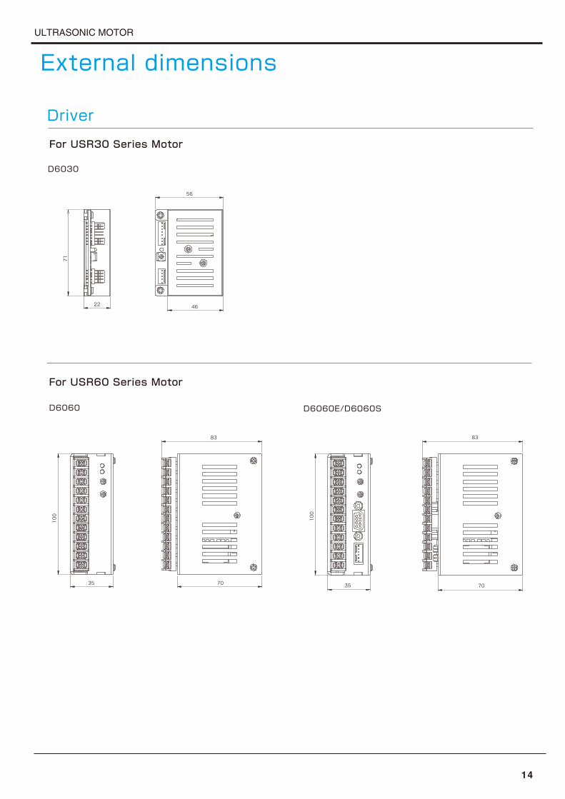
For USR30 Series Motor
D6030
22
71
46
56
For USR60 Series Motor
D6060 D6060E/D6060S
35
100
70
83
35
100
70
83
Driver

ULTRASONIC MOTOR
15
Model Name
Drive Frequency
Drive Voltage
Rated Output
Maximum Output
Rated Speed
Maximum Speed
Rated Torque
Maximum Torque
Holding Torque
Response
Direction of Rotation
Temperature Range
Temperature Limit
Humidity Range
Endurance Time
Size
Weight
Remarks
47KHz~52KHz
110Vrms
1.3W
2.5W(by Maximum Load)250rpm
300rpm
0.05N・m(0.5Kg・cm)0.1N・m(1.0Kg・cm)0.1N・m(1.0Kg・cm)
Less than 1 [ms] ( No-load )
CW, CCW
-10℃~+55℃Surface of Stator 70 [℃]
0~+45 [%] ( without condensation )
2,000Hours
USR30-E3
36×50×48mm
64g
Resolution of Encoder:500P/R
USR30-B4
30×40×44.5mm
19g
Double Shaft
30×40×25mm
17g
Single Shaft
USR30-B3 USR30-S4
36×44×44.5mm
45g
Double Shaft
USR30-S3
36×44×30mm
43g
Single Shaft
USR30-E3T
36×50×48mm
64g
Resolution of Encoder:1,000P/R
Specification
USR30 Series/For General Environment Motor
USR60 Series/For General Environment Motor
40KHz~45KHz
130Vrms
5.0W
10.0W(by Maximum Load)100rpm
150rpm
0.5N・m(5.0Kg・cm)1.0N・m(10.0Kg・cm)1.0N・m(10.0Kg・cm)
Less than 1 [ms] ( No-load )
CW, CCW
-10℃~+55℃Surface of Stator 70 [℃]
0~+45 [%] ( without condensation )
1,500Hours
USR60-S4
67×77×60mm
261g
Double Shaft
67×77×47.5mm
258g
Single Shaft
USR60-S3 USR60-E3T
67×77×66mm
266g
Resolution of Encoder:1,000P/R
USR60-E3
67×77×66mm
266g
Resolution of Encoder:500P/R
Model Name
Drive Frequency
Drive Voltage
Rated Output
Maximum Output
Rated Speed
Maximum Speed
Rated Torque
Maximum Torque
Holding Torque
Response
Direction of Rotation
Temperature Range
Temperature Limit
Humidity Range
Endurance Time
Size
Weight
Remarks

ULTRASONIC MOTOR
Specification
16
USR30-E3NT
36×50×48mm
69g
Resolution of Encoder:1,000P/R
USR30-E3N
36×50×48mm
69g
Resolution of Encoder:500P/R
USR30-S3N
36×44×30mm
48g
Single Shaft
USR30-S4N
36×44×44.5mm
50g
Double Shaft
47KHz~52KHz
110Vrms
1.3W
2.0W(by Maximum Load)200rpm
250rpm
0.05N・m(0.5Kg・cm)0.1N・m(1.0Kg・cm)0.1N・m(1.0Kg・cm)
Less than 1 [ms] ( No-load )
CW, CCW
-10℃~+55℃Surface of Stator 70 [℃]
0~+45 [%] ( without condensation )
1,000Hours
Model Name
Drive Frequency
Drive Voltage
Rated Output
Maximum Output
Rated Speed
Maximum Speed
Rated Torque
Maximum Torque
Holding Torque
Response
Direction of Rotation
Temperature Range
Temperature Limit
Humidity Range
Endurance Time
Size
Weight
Remarks
40KHz~45KHz
130Vrms
5.0W
10.0W(by Maximum Load)100rpm
150rpm
0.5N・m(5.0Kg・cm)1.0N・m(10.0Kg・cm)1.0N・m(10.0Kg・cm)
Less than 1 [ms] ( No-load )
CW, CCW
-10℃~+55℃Surface of Stator 70 [℃]
0~+45 [%] ( without condensation )
1,500Hours
USR60-S3N
67×77×47.5mm
250g
Single Shaft
USR60-E3N
67×77×66mm
272g
Resolution of Encoder:500P/R
USR60-E3NT
67×77×66mm
272g
Resolution of Encoder:1,000P/R
USR60-S4N
67×77×60mm
254g
Double Shaft
Model Name
Drive Frequency
Drive Voltage
Rated Output
Maximum Output
Rated Speed
Maximum Speed
Rated Torque
Maximum Torque
Holding Torque
Response
Direction of Rotation
Temperature Range
Temperature Limit
Humidity Range
Endurance Time
Size
Weight
Remarks
USR30 Series/For Nonmagnetic Compatibility Motor
USR60 Series/For Nonmagnetic Compatibility Motor

ULTRASONIC MOTOR
SpecificationDriver
17
DC24V±0.5V(DC12V±0.5V)
Voltage feedback
Pseudo Sine Wave
Frequency Modulation Method
Over 10 [MΩ] (Motor Unconnected)
1[KVAC] (Motor Unconnected)-20℃~+80℃-10℃~+60℃
Switing TTL Level Voltage
Less than 50 [ms](No inertial load)Less than 1 [ms](No inertial load)
DC0V~3.2VToggle Switch(ON-OFF-ON)
10 [KΩ],0.1[W],B type
Power Source Voltage
Oscillation Waveform
Oscillation Frequency
Speed Adjustment Method
Frequency Control
Motor Drive Voltage
Consumption Current
Over Current Protection
Insulation Resistance
Storage Temperature
Withstand Voltage
Working Temperature
Start-Stop Control
Starting Response
Stopping Response
No-load Speed Range
Speed Control Voltage
Recommended Switch
Weight
Outline Size
Remarks
Recommended Volume
Model Name
47KHz~52KHz
Vertical x Horizontal x Height:56 [mm]×71 [mm]×22 [mm]
110Vrms
DC24V:0.8ADC12V:1.5A
24V:0.8A(φ5.2 Midget Fuse)12V:1.5A(φ5.2 Midget Fuse)
30rpm~300rpm
105g
D6030/24V(12V)
Vertical x Horizontal x Height:35[mm]×100 [mm]×83 [mm]
40KHz~55KHz
130Vrms
DC24V:2.0ADC12V:4.0A (Except D6060S)24V:2.5A(φ5.2 Midget Fuse)12V:4A(φ5.2 Midget Fuse) (Except D6060S)
20rpm~150rpm
250g
D6060/24V(12V)
Encoder feedback
15rpm~150rpm
D6060E/24V(12V)
260g
Speed control function usingencoder signal
D6060S/24V
280g
Speed control function usingencoder signal.Release of light fixation by voltage boost circuit.
DC24V±0.5V

ULTRASONIC MOTOR
Q&A
About support
For support on SHINSEI products,Please refer to the web site.
http://www.shinsei-motor.com/support/index.html
Are there any special precautions in the usage
environment and storage environment?QDue to the structure of the ultrasonic motor, the constituent material
of the motor expands or deforms depending on the preservation
environment, and the characteristics of the motor may change.Please
keep as low humidity condition as possible when storing. Also, please
heat dissipate so that the case temperature does not exceed 55 ℃.
A
Can I use it in a vacuum environment?QI'm sorry. In our current lineup there is no product for vacuum compat-
ibility. However, we plan to announce new products such as
vacuum-compatible motors in the future.A
How can I use a nonmagnetic compatible
motor in a magnetic field environment?QOur USR - N series can be operated with a magnetic field of 3
[T] or more. These motors operate stably in MRI equipment and
superconducting experiment equipment.A
Can I use a cable other than the standard
cable?QSince it may be possible, please contact us.A
QSince it may be possible, please contact us.A
Is there a demonstration machine lending?QI'm sorry. We do not have demonstration machines for rent now. For
customers who want to check the behavior of ultrasonic motors, our
sales staff will show you a demonstration.A
Is there any necessary equipment to move
the Ultrasonic Motor?QIn order to move our ultrasonic motor, in addition to our driver,
· One pole double throw intermediate stop switch for
rotation stop signal(CW/CCW/STOP Control),
· One 10KΩ B type variable resistor,
· One power supply capable of 24 VDC output is required.
※About power supply
If the motor to be used is the USR 30 series, prepare at
least 1A. For the USR 60 series, please have equipment
with capacity of 2.5 A or more.
In addition, when performing speed control using external
signals, a power supply capable of outputting 0 to 3.2 V or a
DAC board etc. is required separately.
A
Contact Us
● For product inquiries Sales department FAX.03-3329-0066 E-Mail:[email protected] ※Business hours(10:00~18:00) weekends off
● Inquiries on technical contents
Technical & Development department E-Mail:[email protected]
18
How is the endurance time calculated?QA
Is torque control possible?QCan not. It is speed control only.A
It is the actual operation time at 23 ° C · 50% environment and no
load.
Is it possible to custom-order, such as
changing the length of the shaft?

Warning
1. Avoid applying excessive load and excessive inertial load to the motor as much as possible. This condition may shorten motor life due to wear of stator and rotor.2. Do not apply a thrust load to the output shaft of the motor. It may cause deterioration of motor characteris tics.3. Do not apply torque greater than the holding torque from the outside when the motor is stopped. There is a possibility of destroying the motor.4. The tolerance of the motor output shaft is g6 finished. Avoid fitting into the output shaft by press fitting or hitting.
5. Please ensure that the case temperature of the motor does not exceed 55℃.6. When using and storing the motor, please keep the humidity around the equipment below 45%.7. The motor is adjusted as a set on the driver and cable. Please readjust the driver when changing the combina tion or changing cable length.8. Prepare a power source for the driver that has enough power capacity.
Please pay special attention to the following points
■ Manufacturer ■
2-1-8 KASUYA SETAGAYA-KU TOKYO 157-0063 JAPANFAX.+81-3-3329-0066 http://www.shinsei-motor.com Email:[email protected]