sustainable facade in tension ˜˚˛˝˙˛˚ˆˇ˘ 2323 sustainable facade in tension figure 1....
TRANSCRIPT

20 21 20 21 © 2012 enclos
The new Seattle, Washington headquarters campus for the world’s largest philanthropic organization targets aggressive sustainable performance with maximum transparency by utilizing curtainwall and specialty-glazed structures. A transparent glass atrium serves as the primary entry, centrally located and programmatically versatile with grandeur to host receptions, banquets or other events. The atrium features two custom point-clamped glass walls supported by a series of slender vertical cables, elegant by design and innovative in their responsiveness to programmatic demands, climatic context and an aggressive project schedule. The lantern-like portal acts as a fulcrum between indoor and outdoor space, while establish-ing a strong connection to the immediate public realm and emphasizing the benevolent character of the Foundation. The atrium’s point-supported approach minimizes thermal bridges within the envelope and exemplifies the degree of high-performance that can be attained outside the traditional curtainwall facade paradigm to achieve a transparent environment with sustainable priorities.
Sustainable Facade in Tension
Jeffrey Vaglio, PE, LEED AP [BD+C]
Mic Patterson, LEED AP [BD+C]
Original paper and presentation for the
2011 Building Enclosure Sustainability Sympo-
sium: Integrating Design & Building Practices at
Cal Poly Pomona.
Seattle Family Foundation Campus
Sean Airhart | NBBJ

22 23 22 23 © 2012 enclos
Sustainable Facade in Tension
Figure 1. Aerial view of the Foundation head-
quarters under construction. Photo taken from
the southwest, atop the Space Needle
observation deck.
1 INTRODUCTION
The Foundation currently has more than 900 employees working in various locations. Looking to unite locations and increase capacity to 1,500 employees, the Founda-tion conceptualized a new sustainable campus located in the heart of Seattle which reflects their values and mission. The first phase broke ground in July 2008 and includes the construction of two sweeping boomerang-shaped six-story structures, resulting in 900,000 square feet of office, event and visitor space. Phase One was completed in spring 2011. A third build-ing will be constructed in a second phase, adding 400,000 square feet. Utilizing a whole-building approach for Phase One, the project team was able to achieve a balance of transparent aesthetics and sustainable performance by evaluating the enclosure and mechanical systems hand-in-hand. The facade program includes in excess of 300,000 square feet of surface area and uses multiple custom systems to enclose the office spaces. The atrium’s tensioned sup-
port structure sits at the core of the campus and is designed to meet high performance, security and blast requirements. The atrium facade structure and glazing attachments are completely exposed to the interior space, requiring the highest level of craftsmanship throughout every aspect of construction. The atrium’s tension structure, in combination with high-performance argon-filled insulated glass units, is an example of how facade and mechanical engineers can collaborate to leverage the thermal advantages of point-supported systems — in comparison to conventional curtainwall systems — to attain aesthetic and aggressive sustainable performance goals.
2 SITE CONTEXT
The Foundation sits on a 12-acre pentagonal site in the backyard of Seattle’s iconic struc-ture, the Space Needle. The site, formerly a city-owned and operated parking lot, is located adjacent to Seattle Center, a cultural center with a storied history of regional and international gatherings.
The site is well connected with the metro transit system, including bus stops along the west and northeast boundaries of the campus and a 0.3 mile walk to the Seattle Center Monorail terminus to the southwest — adjacent to the Frank Gehry-designed Experience Music Project. In order to provide adequate parking for the campus (700 spaces total), a new public-private partner-ship between the city and the Foundation was established to build the multi-level LEED Gold certified Seattle Center 5th Avenue N Garage. Garage construction began in Janu-ary 2007 and opened for operation in July 2008. The parking structure includes a visi-tor center and 1.4-acre living green roof that replaces 12-acres of surface parking [2]. The green roof is covered in sedums and natural plants to reduce the energy consumption approximately 40% compared to similar structures, as well as reduce the rainwater runoff by 90% [5]. The two buildings con-tinue the sustainable initiative adopted by the Foundation to develop an environmentally conscious headquarters campus.
3 BUILDING ENERGY DESIGN
The new headquarters design prioritizes resource conservation in creating a healthy work environment. The building was de-signed with an array of sustainable features, ultimately reducing energy consumption 25% lower than code requirements. A notable sustainable feature on the campus is over a half an acre of green roofs, which re-duce the urban heat island effect and create on-site water conservation through rainwater harvesting. Local and recycled materials are used throughout the building structure, in addition to extensive daylighting of the interior spaces. These features are designed to interact with and complement one another while simultaneously defining the building and landscape aesthetically.
The atrium’s glass includes a low-e coating applied to the inner surface of the outer-most pane (number 2 surface) to provide solar control and moderate the visible light transmittance characteristics with a relatively
color-neutral coating. These insulated glass units with low-e coating and argon gas fill are designed to reduce heat loss but permit solar gain — a solution most appropriate for a heating dominated climate such as Seattle. The extensive use of low-e glass with argon fill throughout the project was critical in meeting the reduced energy targets and permitting expansive areas of transparency throughout. The extensive use of glass also reduces the need for electrical lighting dur-ing the day.
An under floor air distribution system is used throughout the project for ventilation. In the atrium, where air exchange rates are high due to its entry function, a series of operable tran-soms are provided above each door to extract heat or provide natural ventilation during mild seasons. The enclosure and mechanical systems at the atrium lobby achieve the high-performance demands required to support the whole-building energy efficiency goals.
Figure 2. Atrium layout building plan at Level 3.

24 25 24 25 © 2012 enclos
4 ATRIUM FACADE DESIGN
The Atrium facades include the exterior glass curtainwall and cable systems on the south-east and southwest faces of the podium, as illustrated in Figures 2 and 3.
4.1 DESIGN LOADS
The glazing system was designed for +20/-20 PSF wind loads in typical conditions and +20/-30 PSF for corner zones in compliance with ASCE 7-05 Minimum Design Loads for Buildings and Other Structures [1] and the International Building Code, 2006 with City of Seattle Amendments [4]. Seismic design forces were also considered in accordance with ASCE 7-05, 13.3 (ASCE/SEI, 2006).
Additional superimposed loads at the Level 5 roof deck by others at the atrium structure include:
• Green Roof Dead Load Dgr = 47 PSF
• Office Type 2 Dead Load Dof2 = 17 PSF
• Green Roof Live Load Lr,gr = 25 PSF
• Office Type 2 Live Load at Level 5 Lr,of2 = 80 PSF
Sustainable Facade in Tension
Figure 3. Atrium facade elevations; southwest (left) and southeast (right).
Figure 4. Superimposed roof load diagram.
4.2 GLAZING
Typical glass panels are 6’-8” wide x 7’-0” tall, fully tempered insulated units with glass edges set ¾” apart to create a joint filled with sealant to the exterior, foam backer rod infill, and a custom gasket lining the interior. These fully-tempered insulated glazing units have a 1.7” nominal thickness composed of 0.370” SB70XL outer light, 0.50” argon-filled air space, and 0.80” laminated inner lite composed of two 10mm lites with a 0.06” interlayer (Figure 5, top).
The insulated glass unit (IGU) edge deflec-tion limit is L/140, or 0.6” along the 84” height of the typical panel. Using a finite element analysis (FEA) to simulate the composite interaction between the IGU layers and point support conditions at each corner located 5” off center, the critical edge deflection was <0.48” — within the permissible limits (Figure 5, bottom).
Atypical units along the corner and edge conditions were evaluated in a similar fashion to validate the glass units adhere to the stress and deflection criteria. The edge panel proved to be the most stressed glazing panel under design loads due to asymmetrical support conditions: continuous support along one vertical side, and one opposite corner with a relative displacement Δ=1.27” forcing the planar rectangle into a warped condition.
4.3 FITTING ATTACHMENT
The cable fitting assembly is a custom attach-ment designed to transfer loads from the exterior insulated glazing units to a one-way vertical support cable structural element. The cable clamp glass fitting is comprised of four primary components cast out of AISI Type 316 stainless steel: cable clamp back, cable clamp front, fitting armature, and patch plate elements. Additional connection components include neoprene pads, ¼”Ø stainless steel patch plate screws (4 ea.), ½”Ø stainless steel pin (2 ea.), 1”Ø stainless steel threaded stud (1 ea.) and 5/8”Ø stainless steel cable clamp bolts (2 ea.). The components are diagramed in Figure 6, though connection components are excluded for clarity.
Figure 6. Fitting views; assembled (left) and exploded (right).
Figure 5. Atrium insulated glass unit composition (top) and FEA analysis (bottom).
26 27 26 27 © 2012 enclos
4.4 STRUCTURE
The atrium facade support structure consists of 29 vertical 28mmØ stainless steel cables, each pre-tensioned with 48,000 lbs of initial axial force. The top connection of the vertical member is achieved with an open swaged fitting at the cable’s end, pinned to a gusset plate which cantilevers 4” outward from the primary W18 box beam structural member at the roof (Level 5, 57’-9” above ground level). The preliminary engineering for the top con-nection gusset plate anchor was performed by the facade contractor; however, the fabrication of the steel tab was performed by the steel contractor in a controlled shop environment prior to arrival at site. Ultimately a survey was performed in-situ to validate that the top pin locations adhered to a field tolerance of +/- 3/8” of the design location.
As the vertical cable is stretched to the bot-tom connection it penetrates a metal panel soffit at Level 2, 12’-6” above ground level, where the insulated glazing terminates and a series of portal doors are recessed 10’-7” (Figure 8, left). Because the cable is exposed to interior and exterior temperature ranges, the metal panel penetration for each cable is oversized to accommodate field tolerance and thermal expansion. A flexible gasket is used at the penetration to complete the weather barrier around the cable.
Approaching ground Level 1, the vertical member transitions from 28mmØ stainless steel cables to a 48mmØ high strength stainless steel threaded rod to allow it to anchor to a series of cable box terminus con-
Sustainable Facade in Tension
nections. The transition between the cable and rod occurs at a hinge connection 15” above the finished plaza level where the axial cable load is transferred through the open-swaged end fitting of the cable to the closed-swaged end of the rod (Figure 8, right). The finished stone is notched at each cable and sealed with a neoprene closure. The plaza’s stone pavers at each cable serve as access panels for inspection and maintenance of a 5’-0” deep trench which houses the bottom cable box connections. Each cable box is comprised of a HSS 12x8x5/16 cantilevered element which is welded to an embed face plate within the concrete foundation. The HSS is penetrated by a 5” standard pipe sleeve which allows the threaded rod to penetrate before being fas-tened below with a threaded nut and a series of plate washers. The cable box is amended with steel plates and stiffener elements to form jacking seats to accommodate the pre-tensioning process during installation; this is discussed later in further detail.
Though the combined length of the cable and rod vertical member is 61’-6”+ total, the free-span for the cable member occurs between the top connection and a bracing strut at the soffit Level 2. The free-span behind the glazing is 45’ with deflection criteria of L/50 permitting maximum cable deflections of 10.80” under loading. A computerized analysis model of the southeast and southwest atrium cable facades was created using the software program SpaceGASS. The previously introduced design loads were applied, after which the software determines the structural and deformational responses of the members, taking in to account the relative stiffness of
Figure 7. Interior view of the cable wall structure
with stainless steel fitting clamps.
the primary building structure. The maximum cable deflection under loading was Δmax = 8.4” occurring mid-span along the southeast facade. The flexibility of the facade support tension structure requires the boundary structures below and above to absorb large axial forces, which in turn minimizes the cable member sections to maximize transpar-ency throughout the atrium enclosure.
5 THERMAL PERFORMANCE
The typical curtainwall systems for the project included several mockups: visual, performance and blast testing. The atrium facade included a physical mockup only for performance testing. The thermal perfor-mance of the point-supported atrium glazing was determined using computer simulation and physical testing in accordance with the National Fenestration Ratings Council (NFRC) standards to obtain the system’s U-values and solar heat gain coefficient (SHGC) to validate their compatibility with target performance values utilized in energy modeling.
5.1 NFRC TESTING
The purpose for implementing NFRC certifi-cation requirements on the Seattle Foun-dation project was to ensure the site-built product met or exceeded target performance values established earlier in the design process by the mechanical engineer. The enclosures’ role in the energy performance was fundamental in supporting the ambitious LEED targets for the project. The NFRC procedures also ensure that the values are calculated using uniform and accurate means.
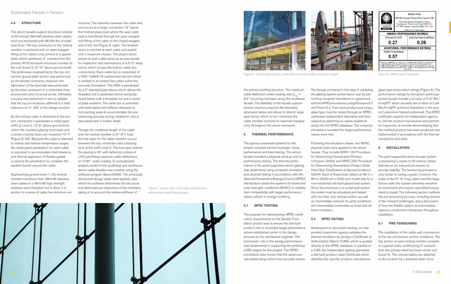
Figure 8. Construction photos; soffit (left) and bottom cable connection (right).
The facade contractor’s first step in validating the glazing system performance was by per-forming computer simulations in agreement with the NFRC procedures, using Windows 5.2 and Therm 5.2. Then each product and unique glass type must be tested through an NFRC authorized independent laboratory and their respective performance values loaded di-rectly into the NFRC database. The computer simulations revealed the target performance values were met.
Following the simulation phase, two NFRC physical tests were applied to the atrium facade. They include NFRC 100 Procedure for Determining Fenestration Product U-Factors (2004) and NFRC 200 Procedure for Determining Fenestration Product Solar Heat Gain Coefficients at Normal Incidence (2004). Each of these tests utilizes an 80 in. x 80 in. (2032 mm x 2032 mm) model size for a non-residential site-built glazed wall system. Since the enclosure is a curtainwall system the model must be simulated and tested with two lites, one vertical mullion, as well as intermediate verticals for jamb conditions and intermediate horizontals as head and sill frame members.
5.2 NFRC RATING
Subsequent to successful testing, an inde-pendent inspection agency validates the thermal simulation by issuing a Certificate of Authorization Report (CAR), which is posted directly to the NFRC database. In parallel to a CAR, the independent agency generates a site-built product Label Certificate which identifies the specific product, manufacture,
glass type and product ratings (Figure 9). The performance ratings for the atrium point-sup-ported facade include a U-value of 0.27 Btu/hr-sqft°F, which exceeds the U-value of 0.34 Btu/hr-sqft°F achieved elsewhere in the proj-ect’s aluminum framed curtainwall. The NFRC certificate requires the independent agency to visit the product manufacture and perform an inspection of records demonstrating that the certified product has been produced and implemented in accordance with the thermal simulations and tests.
6 INSTALLATION
The point-supported atrium facade system is backed by a series of 29 vertical cables that rely on an induced pre-tension to provide stability. The tensioning process is very similar to tuning a guitar; however, the scale of the 61’-6” long cables and the large forces make the system extremely sensitive to movements and require specialized equip-ment to install. The following section outlines the pre-tensioning process, including several of the inherent challenges, and a discussion of how the flexible system accommodates rigorous construction tolerances throughout installation.
6.1 PRE-TENSIONING
The installation of the cable wall commences at the top and bottom anchor conditions. The top anchor of each vertical member consists of a gusset plate cantilevering 4” outward from the primary steel box beam at the roof (Level 5). The vertical cables are attached at this location by a stainless steel clevis
Figure 9. NFRC Label Certificate.

28 29 28 29 © 2012 enclos
REFERENCES
[1] ASCE/SEI 7-05. (2006). Minimum Design
Loads for Buildings and Other Structures. Reston,
Virginia: American Society of Civil Engineers.
[2] Barr, B. (2009). In Seattle, Gates Foundation
Campus Takes Shape. Retrieved December 11,
2011, from Architectural Record: http://archrecord.
construction.com/news/daily/archives/
090811gates.asp
[3] Bill and Melinda Gates Foundation. (n.d.).
Building a Sustainable Campus. Retrieved January
05, 2011, from Bill and Melinda Gates Foundation:
http://www.gatesfoundation.org
[4] City of Seattle. (2007, October). Seattle
Building Code: As Amended by the City of Seattle
2006. Retrieved December 12, 2010, from Seattle.
gov: Dept. of Planning and Development: http://
www2.iccsafe.org/states/Seattle2006/seattle_
building/building_frameset.htm
[5] McConnell, S. (n.d.). Featured Stories: Rethink
the Source. Retrieved 01 05, 2011, from NBBJ:
http://www.nbbj.com/#work/client-stories/gates-
foundation
Sustainable Facade in Tension
Figure 10. Bottom anchor box with jacking assembly
attached (left) and tension meter mounted to verti-
cal cable during installation (right).
condition with a stainless steel pin, releasing the connection for rotation when the cable is subject to lateral load. Each of the cable’s bottom end is attached to a threaded rod near the ground level. This rod penetrates the bottom anchor box, which cantilevers from a welded connection to a steel embed plate within the concrete foundation. On the underside of the bottom anchor box the threaded rod is restrained by a large nut upon a series of stepped plate washers. At this point the cable rests in place under grav-ity, although the system requires an induced pre-tension to provide stability.
Using the bottom anchor box as a jacking seat, a custom jacking assembly is used to mount two 20-ton hydraulic canisters to the cable (Figure 10, left). The hydraulic canisters are tied back to a control manifold which supplies the pressure required to expand the canisters, thus elongating the cable. The axial tension in the cable is monitored by a tension meter (Figure 10, right) that is tied back to an electronic interface that provides readings. The tension meter is calibrated on a project sample cable by an independent testing agency prior to being used in the field.
There is an anticipated 2 3/8” cable elonga-tion associated with the 48,000 lbs preten-sion for the atrium system. This differential is marked on the vertical rod at the bottom anchor box, and is used as a visual guide to assist installation crew identify when the ca-ble should be nearing the design forces. The cable is stretched to its target tension, taking into account an adjustment factor based on the temperature at the time of installation, and the nut beneath the bottom anchor box is tightened along the threaded rod. The tightened nut solidifies the transfer of the
pre-tension forces from the cable, through the anchor box and back into the building foundation. At this time, the hydraulic pres-sure is released and the jacking assembly relocated to the next cable.
Several issues arise during the tensioning process of a one-way vertical cable, includ-ing member twisting and load distribution. The tendency of the one-way cable to twist under axial loads can result in undesired alignments of connection fittings. On the Foundation’s atrium, the cable twisting had to be mitigated to ensure the exposed cable-to-threaded rod connection exposed above the plaza level was consistently oriented perpendicular to the elevation. Each cable was rotated 15 degrees clockwise prior to imposing the pre-tension forces. As the cable gradually received the pre-tension it began to rotate counter-clockwise towards its desired perpendicular final position. It is important to account for the effects of twist-ing prior to tensioning, as the large forces present challenges in rotating the cable or fittings while under loading. Modifications would require a release of the pre-tension and a repeat of the process.
Another issue that arises during the tension-ing process relates to the balancing of loads as the boundary structure — in this case the roof steel — deflects and adjusts with the addition of each pre-tensioned cable. This behavior is studied using installation sequence simulations in a structural analysis tool prior to field installation. Each cable is pre-tensioned to a target pre-pretension design — pre-tension multiplied by adjust-ment coefficients for site temperature and the sequential location of the cable. Following the pre-tensioning of all 29 cables, the system
is given a minimum of 100 hours to settle before a second round of tension meter measurements are performed to validate each cable’s pre-tension is at the target 48,000 lbs, or within an acceptable variance of +/- 5%. Once verified, the cables are ready to receive the clamp fittings and ultimately the insulated glazing units.
6.2 TOLERANCES
The atrium facade’s major challenge was tight tolerances required for the glass and point-supported fittings. The facade had to meet a final face of glass location within 1/8” tolerance in any direction. However, the system is designed to accommodate primary structural tolerances of 1” in any direction for steel and ¾” in any direction for concrete. The cable wall used precision surveying prior to installation, as well as built-in accommodation points at the bottom connection and within the patch-clamp fitting armature. The bottom anchor box included an oversized pipe sleeve through the HSS to allow the threaded rods to penetrate and be restrained to the underside. The oversized hole provided more than the 1.50” tolerance required in the side-to-side and in-out direc-tions. Each clamped cable fitting with patch plate attachments for the glass provided adjustability in every direction. Vertically, the clamp could be slid up and down the cable and re-clamped. The patch plates attach to the spider armatures with a stainless steel pin at a slotted connection that also permits movement under a seismic event. The as-sembly provides in-out adjustability with the 24mmØ stainless steel threaded stud which joins the spider armature to the cable clamp front component. Once the in-out location is set by the threaded stud a set screw (which
penetrates the top of the spider armature) is locked into place, engaging the two to-gether. The flexibility of the tensioned cable wall exists not only under deflection, but also in its versatility in installation relative to other trades.
7 CONCLUSIONS
The Foundation headquarters feature one of the largest structural glass facades in the United States. The one-way cable facade is a high-transparency system on a highly-sustainable project which integrates innovative structural facade solutions with the latest in IGU insulating performance. The performance of the cable walls was also op-timized in its consideration of the installation process during design development. The efficient termination condition at the bottom anchor boxes is just one example of leverag-ing the installation process and equipment as a driver in the engineered design. The atrium’s point-supported approach optimizes thermal performance within the envelope and exemplifies high performance that can
be attained outside the traditional curtainwall facade paradigm to achieve a transparent environment with sustainable priorities. The efforts of the architect, supported by various consultants, produced a building that is energy efficient and ultimately seeks LEED Gold certification from the United States Green Building Council. It stands as both an expression of the Foundation’s commit-ment to green architecture and a powerful example of the opportunities presented by structural glass facades.
ACKNOWLEDGMENTS
The Foundation was completed in spring 2011 as the result of intense collaboration between many firms, individuals, consultants and contractors. Key project team members include: NBBJ (architect), ARUP (structural engineer, MEP and sustainability consul-tants), Gustafson Guthrie Nichol Ltd (land-scape design & sustainability consultants), Sellen Construction (general contractor), and Enclos (design/assist and design/build facade contractor).