switchgear controls - electricalpartmanuals.com
TRANSCRIPT

51-EMENS ... ALLIS
Maintenance
Guide for a . Switchgear Periodic
Maintenance rogram
SG3388 www . El
ectric
alPar
tMan
uals
. com

www . El
ectric
alPar
tMan
uals
. com

·coNTEN TS
TABLE OF CONTENTS
A.
B.
c.
FORWARD
FREQUENCY OF MAINTENANCE
GENERAL RECOMMENDATIONS AND CONSIDERATION
1. 2. 3.
4. s.
Enclosure Moisture Insulation (a) Electrical Distress (b) Corona (c) Tracking (d) Thermal Damage Bolted Joints Lubrication
1
2
3
3 3 4 4 5 5 6 7 7
D. PREPARATION FOR MAINTENANCE & INSPECTION 8
E. MAINTENANCE & INSPECTION PROCEDURE FOR CIRCUIT BREAKERS 9
F. GROUND AND TEST DEVICE 10
G. MAINTENANCE & INSPECTION PROCEDURES FOR CIRCUIT BREAKER 11 COMPARTMENT
H. MAINTENANCE & INSPECTION PROCEDURE FOR MAIN BUS 12 COMPARTMENT
I. INSTALL CIRCUIT BREAKER IN CUBICLE 13
J. INSTRUMENT PANELS 13
K. SERVICE AUXILIARY COMPARTMENTS 14
L. BUS INSULATION TESTS 14
M. RESTORING SERVICE 15
EXHIBIT NO. 1 - MAINTENANCE CHECK LIST FOR VACUUM CIRCUIT BREAKERS 16
www . El
ectric
alPar
tMan
uals
. com

CON TEN TS
EXHIBIT NO. 2 - MAINTENANCE CHECK LIST FOR AIR CURCUIT BREAKERS
EXHIBIT NO. 3 - MAINTENANCE CHECK LIST FOR SWITCHGEAR CUBICLES
METHOD FOR CHECKING OPENING AND CLOSING TIMES
SERVICE TIPS-CIRCUIT BREAKERS IN CORROSIVE ENVIRONMENTS
PRODUCT TECHNICAL DATA
LUBRICATION INSTRUCTIONS FOR LOW VOLTAGE AIR CIRCUIT BREAKER
LUBRICATION INSTRUCTIONS FOR 5 & 15 KV AIR MAGNETIC CIRCUIT BREAKER WITH MODEL SE-3 OR SE-4 OPERATOR
LUBRICATION INSTRUCTIONS FOR 5 & 15 KV AIR MAGNETIC CIRCUIT BREAKER WITH MODEL 515 OPERATORS.
LUBRICATION INSTRUCTIONS FOR 34.5 KV VACUUM C IRCU IT BREAKER
GROUND AND TEST DEVICES ( SPECIFICATIONS)
17
18
20
22
24
26
28
35
39
42
www . El
ectric
alPar
tMan
uals
. com

'IN STRUCTION S
FORWARD
This Guide is to provide some additional recommendations and suggestions for the Periodic Maintenance of SIEMENS-ALLIS switchgear cubicles, various circuit breakers and associated metering and relaying.
This Guide is intended to supplement the "INSTALLATION, OPEFATION MAINTENANCE INSTRUCTIONS FOR ELECTRICAL EQUIPMENT" in the Instruction Manuals originally furnished with your equipment and other switchgear products covered in this Guide.
NOTE: Effective January 1, 1978, substantially all of the assets of the former Electrical Products Group of Allis-Chalmers were transferred to a new corporation called:
SIEMENS-ALLIS, INC.
Thus, new products, publications and literature will bear the Siemens-Allis name.
Though all references herein will state Siemens-Allis, they also apply to the Switchgear products labelled Allis-Chalmers.
FIELD SERVICE OPERATION
Page 1
Siemens-Allis can provide competent, well-trained Field Service Representatives to provide technical guidance and
advisory assistance for the installation, overhaul, repair and maintenance of Siemens-Allis equipment, processes
and systems. Contact regional service centers, sales offices or factory for details.
www . El
ectric
alPar
tMan
uals
. com

IN STRUCTIONS
FREQUENCY OF MAINTENANCE
Recommended frequency of maintenance will depend upon environmental and operating conditions, so that no fixed rules can govern all applications. During the first three years of service an annual inspection of the entire switchgear assembly including withdrawable circuit breaker elements is suggested as a minimum. Inspection frequency can be increased or decreased depending on experience.
When operating requirements prevent the shutdown of an entire switchgear assembly for inspection of insulation, a partial shutdown and inspection may dictate a need for a full shutdown to avoid a potential failure. However, conditions in partially inspected areas are not necessarily representative of conditions in energized areas not accessible for inspection.
The following factors will affect the timing of inspections:
(1) Feeder, bus, or system fault occurrence.
(2) Sustained unusual or abnormal operating conditions;
e. g., switching or lightning surges, sustained over-
loads.
(3) Extremes in enviromental conditions, such as
temperature, heavy dust, high winds, rain, fog, smog,
fumes of many kinds, fly ash, salt spray, high humidity, or unusual temperature changes.
(4) Emergency shutdowns.
(5) Scheduled shutdowns.
If the switchgear is installed in an air conditioned room, it would generally not be affected by external environmental conditions. However, if doors are left open or air conditioning is not operating, additional cleaning may be required.
Page 2
www . El
ectric
alPar
tMan
uals
. com

.IN STRUCTION S
GENERAL RECOMMENDATIONS AND CONSIDERATIONS
1. Enclosure
The switchgear enclosure is designed to:
(a) Protect personnel from energized parts and mechanisms.
( b) Protect the equipment from moisture and dust.
2 . Moisture
It is important to keep doors closed and covers bolted in place during operation for the above two reasons.
Moisture accumulation may occur on internal surfaces of enclosure even though they are indoors. The source of this moisture is condensation. When the temperature of any surface drops below the dew point of the air with which it is in contact, condensation will occur.
Water vapor will be added to the internal atmosphere of the switchgear if there is standing water in the vicinity of floor openings or bottom ventilation openings. All floor openings, other than those specifically provided for drainage purposes, should be effectively sealed. All unused conduits or openings around cables at entrance ducts should be sealed with an electrical grade of caulking compound. Standing water should be eliminated permanently.
Conditions causing condensation are intermittent and may not be prevalent at the time of inspection. All internal surfaces should be examined for signs of previous moisture such as:
(1) Droplet depressions or craters on dust-laden surfaces.
(2 ) Deposit patterns, such as might occur if a film of dirty water were left to evaporate on a flat surface.
Page 3
www . El
ectric
alPar
tMan
uals
. com

IN STRUCTIONS
(3) Excessive rust anywhere on the metal housing.
Moisture accumulation is prevented by heat and air circulation. Therefore, it is very important to make sure that space heaters (standard on outdoor; optional on indoor) and thermostats are functioning properly and that the filters are clean.
3. Insulation
With proper maintenance, the insulation materials used in switchgear assemblies are designed for and expected to withstand operating voltages for many years. During this time, the insulation will be subject to cumulative deteriorating conditions which detract from voltage withstand capability.
Moisture combined with dirt is the greatest deteriorating factor for insulation. Even small amounts of moisture (such as condensation) if allowed to accumulate can result in electrical leakage which leads to tracking and eventual flashover.
The surface of all insulating members should be inspected before any cleaning or dust removal, and re-inspected after cleaning. Moisture droplets often leave craters or depressions in a dust layer without staining the member under the dust. Conversely, a carbon track starting to form on a bus support may be completely masked by later deposits of dust.
Insulation can be damaged in the following ways:
(a) Electrical Distress
The following are specific areas in which electrical distress is more likely to occur and should be given special attention:
Page 4
www . El
ectric
alPar
tMan
uals
. com
'IN STRUCTION S
1. Boundaries between two adjoining insulators. 2. Boundaries between an insulating member and
the grounded metal structure. 3. Taped or boot-covered splices or junctions. 4. Bridging paths across insulating surfaces;
either phase-to-phase or phase-to-ground. 5. Hidden surfaces such as the adjacent edges
between the upper and lower member of split type bus supports or, the edges of a slot through which a bus bar protrudes.
6. Edges of insulation surrounding mounting hardware: either grounded to the metal structure, or floating within the insulating member.
Damage caused by electrical distress will normally be evident on the surface of insulating members in the form of corona erosion or markings or tracking paths.
(b) Corona If corona occurs in switchgear assemblies, it is usually localized in thin air gaps that exist between high voltage bus bar and its adjacent insulation, or between two adjacent insulating members. It may form around bolt heads or other sharp projections if not properly insulated or shielded.
Siemens-Allis switchgear has insulation which is not subject to deterioration by corona. However, contamination of surfaces must be prevented.
(c) Tracking
Tracking is an electrical discharge phenomenon caused by electrical stress on insulation. This stress can occur phase-to-phase or phase-to-ground.
Tracking develops in the form of streamers or sputter arcs on the surface of insulation usually adjacent to high voltage electrodes. One or more irregular carbon lines in the shape of tree branches is the most common sign of tracking.
Page 5
www . El
ectric
alPar
tMan
uals
. com
IN STRUCTION S
Surface tracking can occur on the surfaces of organic insulation or on contaminated surfaces of inorganic insulation. The signs of tracking on organic materials are eroded surfaces with carbon lines. On track resistant organic materials these erosion patterns will be essentially free of carbon.
Tracking can propagate from either the high voltage or ground terminal. It will not necessarily progress in a regular pattern or by the shortest possible path.
(d) Thermal Damage
Temperatures even slightly higher than design levels for prolonged periods, can shorten the electrical life of insulating materials. Prolonged exposure to higher than rated temperatures can cause physical deterioration of these materials resulting in lower mechanical strength. Localized heating (hot spots) can sometimes occur but be masked because the overall temperature of the surroundings is not raised appreciably. Infrared inspection on periodic basis is recommended. The infrared sensor can detect the presence of abnormal heat. Loosely bolted connections in a bus bar splice or cable lug connection are examples of this. It can also occur at the primary disconnects if the silver plating corrodes badly due to contaminants in the atmosphere.
Since power should be removed prior to a visual inspection, it is unlikely that temperature itself could be relied upon after shutdown to signal potentially damaging heat. Some external conditions which form the basis for detecting heat damage are:
(a) Discoloration - usually a darkening - of material or finishes.
(b) Crazing, cracking, flaking of varnish coatings.
(c) Embrittlement of tapes and cable insulation.
(d) Delamination.
(e) Generalized carbonization of materials or finishes.
(f) Melting, oozing, or exuding of substances from within an insulating assembly.
Page 6
www . El
ectric
alPar
tMan
uals
. com

IN STRUCTION S
Insulating materials that have been physically damaged should be replaced. In summary, the important things to remember in maintenance of insulation is, KEEP IT CLEAN, KEEP IT DRY AND KEEP IT COOL.
If there is evidence of overheating, determine the cause and correct it. The cause may be excessive dirt on surface,_ plugged ventilation openings, loose hardware, or overloading.
Remember, installations can be checked for overheating by using infra-red testing equipment. The bus and connections can be checked with some of these sensors without removing the rear cover plates.
4. Bolted Joints
All bus joints consist of either silver plated copper, tin plated copper when specified or tin-plated aluminum bus bars secured with 1/2" Grade 5 steel hardware. This hardware is torqued to 50-75 Ft/Lbs (67. 8-101. 7 N·m) at the factory. Shipping split and cable lug hardware must be torqued to these same values during installation. In some applications silicone bronze hardware is used in which case it is torqued to 30-40 Ft/Lbs. (40. 7-54. 2 N·m). When aluminum bus is furnished conical washers ("Belleville " washers) are used to insure maintenance of pressure. There is no reason to expect loosening of hardware during the life of the equipment. On joints which are insulated with PVC boots, glastic caps or tape, it will not be possible to check for loose hardware without removing the insulation. Thus you may not want to check bus joint hardware unless inspection of the insulation shows evidence of overheating.
5. Lubrication
The lubrication of moving parts and electrical contacts is very important. The lubrication provides a degree of protection against corrosion of critical parts.
Corrosion problems in switchgear are primarily caused by the chemical reaction of hydrogen sulfide, or free sulphur acting upon silver-plated contacts. There are other contaminants which are often present in many types of industrial environments such as ammonia, sulphur dioxide, chlorine, and nitrogen peroxide. Any or all of these can
Page 7
www . El
ectric
alPar
tMan
uals
. com

IN STRUCTION S
react adversely on contacts and other plated current carrying parts.
At each maintenance interval, all of the old grease must be wiped off sliding electrical contacts, and new lubricant applied. Be careful not to get grease on adjacent insulation. Apply only Siemens-Allis contact lubricant -(Part No. 15-171-370-002) in a layer between 1/32" and 1/16" thick (. 8 - 1. 6mm) .
See attached lubrication instructions for additional information.
PREPARATION FOR MAINTENANCE AND INSPECTIONS
Before starting work on the switchgear, the following is required:
& DANGER
I. Do not work on energized equipment. Unauthorized personnel should not be permitted near energized equipment. Plan the time for maintenance with operating personnel so that the switchgear can be de-energized, and safely grounded.
NOTE: Switchgear assemblies are enclosed on all sides and top with sheet metal. Access into the enclosure is provided by doors or removable covers. Although the bus and connections are insulated in metal-clad switchgear assemblies, it is a coordinated insulation system: insulation plus air or creep distance equals a given insulation level.
& DANGER
BUS INSULATION IN METAL-CLAD SWITCHGEAR IS NOT DESIGNED TO PREVENT SHOCK. CONTACT WITH THIS INSULATED BUS COULD RE�ULT IN SHOCK, BURNS OR POSSIBLY DEATH.
Page 8
www . El
ectric
alPar
tMan
uals
. com

IN STRUCTION S
See ANSI C37.20-6. 2.4 which is quoted as follows: " This insulating covering is a requirement of metal-clad switchgear and is provided to minimiize the possibility of communicating faults which would result if foreign objects momentarily contacted bare bus. This insulating covering is usually only a part of the primary insulation system and in such cases the outer surface of this insulating covering will not be at ground potential. It should not be assu med, therefore, that personnel can contact this insulating covering with complete safety."
2. Disable any remote control and automatic transfer schemes.
3. Disconnect and ground all potential transformers.
4. Open all disconnects.
Page 9
MAINTENANCE & INSPECTION PROCEDURE FOR CIRCUIT BREAKERS
SEE ATTACHED EXHIBIT #1 AND #2
1. Check the breaker trip potential source.
a. Battery Condition (if used) .
1. Voltage of each cell. 2. Specific gravity of each cell.
3. Cleanliness. 4. Connections, for corrosion, looseness,
electrolysis, etc., including trip circuit connections in all cubicles.
b. Battery Charging Equipment
1. General condition. 2. Fuses and/or circuit breakers. 3. Operation.
c. "ENER/PAC" (if used) check "Push to Test" feature.
2. Select the first cubicle to be maintained.
3. Remove the Circuit Breaker. Inspect and maintain per the appropriate "Maintenance Check List for Circuit Breakers. " www .
Elec
tricalP
artM
anua
ls . c
om
IN STRUCTION S
Page 10
GROUND AND TEST DEVICE
If a ground and test device was furnished, insert this in the circuit breaker compartment and use it in accordance with instruction book furnished for the device and your local safety practices.
CAUTION PRIOR TO GROUNDING EITHER UPPER OR LOWER STUDS, THEY MUST FIRST BE DE-ENERGIZED. Check the single line or three line diagram for the equipment to determine if remote circuit breakers must be opened prior to grounding. The use of the ground and test device in bus tie units is not recommended because one set of studs will be impossible to de-energize without a major shut-down.
Similarly, some cubicles could be back-fed from another bus. A hot stick potential indicator is sometimes used as a check.
& DANGER
IMPROPER USE OF A GROUND AND TEST DEVICE COULD RESULT IN VERY SERIOUS INJURY, SHOCK OR POSSIBLE DEATH.
IT IS IMPERATIVE THAT YOU BECOME TOTALLY FAMILIAR WITH EVERY ASPECT OF A GROUND AND TEST DEVICE BEFORE USING IT. YOU MUST BE C�RTAIN WHICH PRIMARY CIRCUITS CONNECT TO EACH STUD AND IF THEY ARE OR COULD BE ENERGIZED DUE TO BACKFEED. YOU MUST INSURE THAT THE SELECTOR SWITCH IS SET PROPERLY AND THAT THE CIRCUIT IS DE-ENERGIZED BEFORE DOING ANY LOW VOLTAGE (MEGGER) TESTING. MAKE NO ASSUMPTIONS AND DOUBLE CHECK EVERY STEP.
www . El
ectric
alPar
tMan
uals
. com

IN STRUCTION S
MAINTENANCE & INSPECTION PROCEDURE FOR CIRCUIT BREAKER COMPARTMENTS
NOTE Use the "Maintenance Check List -Exhibit 113" with the following procedures:
1. Inspect the Circuit Breaker compartment for moisture, dust, dirt and loose parts. Record data on "Maintenance Check List for Switchgear Cubicles. " Clean as necessary.
£ DANGER
2. IF YOU ARE GOING TO OPEN THE SHUTTERS COVERING THE PRIMARY DISCONNECTS, MAKE CERTAIN THAT BOTH LINE/LOAD AND BUS ARE DE-ENERGIZED FIRST. DO NOT MAKE THIS CHECK FOR BUS TIE UNITS, SOURCE BREAKERS OR UNITS THAT COULD BE BACK-FED UNLESS ALL BUSSES ARE DE-ENERGIZED. FAILURE TO DO THIS CAN RESULT IN SERIOUS INJURY, BURNS OR POSSIBLE DEATH. THEN OPEN THE SHUTTERS AND BLOCK THEM OPEN. USING A HOT STICK POTENTIAL DEVICE, DOUBLE-CHECK THAT ALL DISCONNECTS ARE DE-ENERGIZED.
3. Using a flashlight, inspect the silver-plated primary disconnects for signs of overheating or excessive wear ( Silver-plating worn through to copper). Record condition on check list. Clean and lubricate the silver-plated contacts per instruction book.
4. Inspect the primary disconnect mounting or housing for dust, moisture or unusual appearance. Record condition on check list. Clean insulation with a suitable cleaner per instruction book.
5. Test insulation with a megger on all phases to ground. You would normally not be as interested in what your megger reading is, but rather what it shows in respect to previous readings and whether they are approximately the same or are decreasing or increasing. Systematic periodic use of the megger ( always use same rating megger) will provide you with
Page 11
www . El
ectric
alPar
tMan
uals
. com

IN STRUCTION S
invaluable information. There are no rule-of-thumb formulas for exact values of insulation resistance owing to the variations in materials used and how they were built up, moisture, temperature, surface leakage etc. For many years maintenance personnel have used the 1 megohm per kV plus 1 megohm with a 1 megohm minimum as a general guide. This could be acceptable in some cases and would allow you to energize. Our experience has shown that typically 50 megohms on 480V - 600V class switchgear and 200 megohms on 5 kV - 15 kV and 38 kV class is what you should look for. These values would be with the breakers removed and typically you would look for 150 megohms with breakers in connect position and closed, on the 5 - 15 and 38 kV equipment or 35 megohms on the 480-600V. Important: When you megger each phase to ground look for any differences in those readings. All 3 phases to ground should be very close and if not look for the cause and correct.
6. Return shutters to closed position. Check for ease of operation to be sure they close and open freely. Lubricate operating linkage as required.
7. Inspect the current transformers.
8. Inspect other items in the circuit breaker compartment per the check list.
9. Remove old lubricant and lubricate auxiliary switch contacts with Part No. 15-171-370-002, Siemens-Allis Electrical Contact Lubricant.
Page 12
MAINTENANCE & INSPECTION PROCEDURE FOR MAIN BUS COMPARTMENT
1. Make sure the bus and cables are de-energized. The ground and test deivce can be used in any of the feeder compartments to ground the bus. See Section "F".
2. Remove the bolted access plates. These are usually split to facilitate removal with the power cables in place.
3. Inspect the compartment per the check list. www . El
ectric
alPar
tMan
uals
. com

IN STRUCTION S
NOTE The main bus compartment is designed for maximum reliability since a shutdown is usually required to de-energize the bus section for maintenance. The insulated bus is well supported and generous creepage distance is provided. The space heaters, when furnished, project into the bus compartment to minimize condensation. Nevertheless, inpection of the bus compartments is important to insure that all surfaces are clean and dry and that there are no signs of tracking or corona.
4. Clean insula�ng surfaces. Correct the cause if signs of overheating are present.
5. Replace bolted covers of bus compartment.
6. Remove the ground and test device.
Page 13
INSTALL CIRCUIT BREAKER IN THE CUBICLE
Refer to Instruction Book.
Place the circuit breaker in the cubicle in the test position.
Energize control circuit. Using the control switch close and trip the circuit breaker in the test position to verify its performance. Note-this will also verify performance of the control power source, (battery or control power transformer etc.) control wiring, control circuit fuses, shunt trip coil, and capacitor trip or ENER/PAC (if used) .
J. Instrument Panels
NOTE: Most meters and instrument transfer switches can be checked while the switchgear is energized. Tests of overcurrent relays can be performed while the switchgear is energized. Refer to the product instruction books for details.
All overcurrent relays would probably have been set in accordance with a "Coordination Study" which was prepared prior to initial installation. Check or recheck relay settings, instrument and control switches, and inspect their contacts. www .
Elec
tricalP
artM
anua
ls . c
om

IN STRUCTION S
K.
Operation of control switches can be checked with the circuit breakers in the test position.
Lockout relay operation should be checked.
Page 14
Automatic transfer and/or manual transfer schemes are designed to operate per a detailed procedure. This procedure must be reviewed and used to check and exercise these schemes.
Service Auxiliary Compartments
Certain units are auxiliary units. These may contain potential transformers, control power transformers, and/or other devices.
£ DAN GER
THE STATIONARY PRIMARY DISCONNECTS OF POTENTIAL AND CONTROL POWER TRANSFORMERS ARE NO��LY INACCESSIBLE. MAKE CERTAIN HOWEVER THAT THESE ARE DE-ENERGIZED BEFORE CLEANING THE COMPARTMENT. FAILURE TO DO SO COULD RESULT IN SERIOUS INJURY, BURNS OR POSSIBLE DEATH. CLEAN THESE TRANSFORMERS AND INSULATORS. CHECK AND CLEAN COMPONENTS IN OTHER AUXILIARY UNITS.
BUS INSULATION TESTS
Refer to Instruction Book.
After completing maintenance of all units in the bus section, test the bus insulation with a SOOV or lOOOV megger. Look for 200 megohms or higher. Pay particular attention to differences in readings from each phase to ground. If differences exist, determine cause.
If desired, a high potential (HI-POT) test can then be performed. This test should be performed at 75% of the factory test level.
Potential transformers, control transformers, lightning arresters, and surge capacitors must be disconnected during this test. www . El
ectric
alPar
tMan
uals
. com

IN STRUCTION S
Page 15
TYPICAL FIELD HI-POT VALUES for primary bus are as shown below. These values are for one minute duration only.
Equipment Nominal Voltage
Ratings
600-volts 4. 16 kV 7. 5 kV
13. 8 kV 34. 5 kV
AC HI-POT
1650 volts 14. 3 kV 27. 0 kV 27. 0 kV 60. 0 kV
DC HI-POT
2333 volts 20. 2 kV 38. 2 kV 38. 2 kV 85. 0 kV
HI-POT values one minute duration for secondary circuits: 1125 volts AC, or 1590 volts DC.
CAUTION Certain control devices such as, charging motors, pushbuttons, bell alarms etc. , may have only a 900 volt rating. 75% of 900V would allow a field HI-POT of only 675 volts AC or 954 volts DC.
Do not HI-POT static trip devices.
M. Restoring Service
After completing the serv1c1ng, return all circuit breakers to their units, close control power supply switches. Check breaker operation in the test position, rack to connect position, connect all potential transformers, arm automatic transfer circuits, close and latch all doors securely, and re-energize.
www . El
ectric
alPar
tMan
uals
. com

CHECK LIST
Vacuum Circuit Breakers Page 16
EXHIBIT NO. 1 CHECK LIST FOR VACUUM CIRCUIT BREAKERS
Dote Installed: Date Serviced: Job No. ------------------
Token From Cubicle I Returned to Cubicle I --------------------- ---------------------
Type _____ _ Rated Volts Rated AMP S/N ----------- ------- ------------------
FOLLOW APPROPRIATE INSTRUCTION BOOK
0 Vacuum Tubes Cleaned. 0 Checked Breaker opening and Closing times.
D Vacuum Tubes "A" Dim. Checked. Record Dim. -------------
0 Vacuum Tubes Hi-Potted. P hose I_ 2 _ 3 _
0 Phose Barriers examined.
0 Checked for Loose Hardware.
0 Charged with Plug Jumper.
0 Closed Breaker Electrically with Control Switch on Panel
0 Checked Position Indicator.
0 Tripped Breaker with Control Switch on Panel
0 Checked position indicator.
0 Depress Trip Rod and Close Breaker with Control Switch on Panel. (Breaker should be trip free).
0 Release Trip Rod, close and Trip Breaker. (Breaker wi II close and trip. )
D Checked and Lubricated Primary Disconnects.
0 Checked and lubricated Secondary Disconnects
0 Checked and Lubricated Auxiliary Contacts.
0 Mechanical Interlocks checked.
0 Electrical Interlocks checked.
0 S. E. Operator checked and lubricated.
0 Ground Contact checked.
0 Limit Switches Checked.
0 Charge-Discharge Indicator checked.
0 Counter - Reading ---------------
0 Alignment in Cubicle correct.
0 Operated in Cubicle test position.
0 AC 0 DC Control Volts -----
-------------------o _________________
o __________________
o ______________ __
0 Breaker Timed: Cycles to Trip: Cycles to Close: ---------- ------------ ------
0 Hi Pot Test ______ Volts 0 AC 0 DC ______________ Misc. AMP.
0 Breaker Placed into Service, Dote: __________________ __
Environmental Conditions: �----��------------------------------Remarks: (Show "Remarks" an reverse side.)
Signed: ______________________ _
SIEMENS·ALLIS
www . El
ectric
alPar
tMan
uals
. com

CHECK LIST
Air C i rcuit Breakers
EXHIBIT NO.2 CHECKLIST FOR AIR CIRCUIT BREAKERS
Date lnstalled:. _______ Date Serviced: _______ Job No.: _
________
_ _
Taken From Cubiclei __________ Retumed to Cubicle '--------------
Type:. _____ Rated Volts: _____ Rated Amp: _____ S/N: _ _________ _
Stored Energy:. __________ Solenoid: ________ Manual: _
________
_
0 0 0 0 0 0 0 0 0 0 0 0 0 0
Arc Chutes Primary Contacts
FOLLOW APPROPRIATE INSTRUCTION BOOK
Auxiliary Contacts Checked Sequence Checked Manual Closure Operated Manual Trip Operated Breaker Cleaned Hardware Tightened Mechanical Interlocks Checked Mechanism Operates Correctly Puffer Operation Correct Breaker Operated With Test Device Alignment in Cubicle Correct Operated in Cubicle Test Position
0 0 0 0 0 0 0 0 0 0
Secondary Contacts Main Contacts Alignment & Penetration Checked Blow-Out Coil Connection Trip Coil Operated FC 1000 Only Blow-Out Coil Polarity Checked and Coil Connection Interference of Breaker to Hinge Wire Breaker Lubricated
Static Trip Unit Set Static Trip Unit Tested Limit Switches Checked
Open-Close, Disch., Indicators Checked Breaker Put in Service
0 AC 0 DC _____ Contral Volts
0 0 0 0
Counter Works Properly - Reading:. ____ _
Ground Contact Checked Environmental Conditions:
·------------------------------------
Megger: DC Volt. Phase 1: Phase 2: Phase 3: ·-----
(When meggering a pole to ground, have the other two poles connected to ground. Megger each primary contract to frame ground.)
• 0 Breaker Timed:. _______ Cycles to Trip:. ________ Cycles to Close • 0 Hi Pot Test: Volts 0 AC 0 DC MicroAMP. • Hinge Joint Pressure: Phase 1: Phase 2: Phose 3:
----- ----------
• Contact Resistance: Phase 1: Phase 2: Phase 3:
• These tests to be performed only if specified.
---------
REMARKS: ___________ ______________________________ _
SIEMENS-ALLIS SIGNED: ______________ _ _
Page 17
www . El
ectric
alPar
tMan
uals
. com

CHECK LIST
Switch gear Cubicle
EXHIBIT NO. 3
MAINTENANCE CHECKLIST FOR SWITCHGEAR CUBICLE
P r e p a r e a c o p y o f t h i s c h eck l i s t f o r e a c h s w i t c h g e a r u n i t . R e f e r t o appr opr i a t e In s t r u c t i o n B o o k f o r d e t a i l e d p r o c e d u r e s . Cubicle Type 0 Indoor 0 Outdoor. Operating Voltage __ kV Date: ____ _
Main Bus continuous current rating, ____ __;Amperes: Serial No."' ______ _
Date of initial service: Unit Number: 0 Prepared for maintenance (Refer to Guide, Para. D & F)
-------------
0 General conditions 0 Dry 0 Damp 0 Clean 0 Dusty 0 Removed circuit breaker 0 Serviced per separate check list. 0 Checked door alignment 0 lubricate hinges.
CIRCUIT BREAKER COMPARTMENT
0 Checked for moistwe, dust and loose ports. 0 Found comportment 0 damp 0 dry 0 clean 0 dusty. O Opena::l shutters &DANGER: - (Refer to Para. G .2)
it,DANGER:- DO NOT open shutters of bus tie units 0 Inspected primary disconnects. 0 Cleaned and lubricated. O Inspected porcelain housing 0 Wiped Clean.
0 Meggered upper disconnects. 0 Phase 1: 0 Phose 2: 0 Phase 3: 0 Closed shutters 0 Checked for easy operation 0 Lubricated 0 Inspected current transformers. 0 Checked for loose wires.
0 Inspected cubicle mounted auxiliary switches 0 lubricated. 0 Inspected space heater and thermo-disc. 0 Checked operation.
CABLE/BUS DUCT COMPARTMENT Lt_ DANGER: CONDUCTORS MAY HAVE BACK FEED
0 Determined that conductors were de-energized. 0 Rem01 ed rear covers 0 Checked gaskets. 0 Inspected for signs of 0 tracking 0 heating:COMMENT:. _______ _
0 Found Comportment 0 Domp 0 Dry 0 Clean 0 Dusty 0 Cleaned oil insulation 0 Inspected and cleaned current transformers (if provided) MAl N BUS COMPARTMENT it, DANGER - DE-ENERGIZE BUS - SEE D 1 0 Determined that conductors were de-energized 0 Removed access covers
* The same serial number applies to all units in this line-up. Obtain serial number from rating plate located in the left end unit.
SIEMENS-ALLIS Sheet #J of 2
Page 18
www . El
ectric
alPar
tMan
uals
. com

CHECK LIST Switch gear C ubicle (Co n't.)
0 Inspected for signs of 0 Tracking 0 Heating. Comment: _______ _
Found compartment 0 damp 0 Dry 0 Clean 0 Dusty
0 Cleaned all insulation 0 Installed access covers
Place Circuit Breaker in cubicle.
0 Checked clearance of breaker with cubic!e hinge wiring. 0 Checked position mechanical interlock. (Rack breaker to position between "Test" and "Connected" positions. Attempt to close breaker. Should be trip-free) 0 Racked to "Connected" position 0 alignment 0. K.
INSTRUMENT PANEL (Refer to Para.J) 0 Checked for broken cases. 0 Checked operation of control switch with circuit breaker in "Test" position. 0 Tripped the breaker by passing sufficient current (or voltage) thru the coils
of protective relays. 0 Examined indicating lamps and replaced as required. 0 Checked terminal block contacts for loose connections.
AUXILIARY COMPARTMENTS &DANG E R REFER TO PARA. K
D D D
Checked potential transformers. 0 Cleaned 0 Checked for loose wires Checked trunnion operation O Verified disconnects making contact.
Checked PT Fuses 0 Primary 0 Secondary
AFTER All UNITS HAVE BEEN SERVICED 0 D 0 0 0 0 D D
Meggered bus (lower disconnects) through ground and test device placed in ony one of the feeder units.
Optiono'l: Performed high potential tests on bus (lower disconnects) through ground and test device (Same as Megger test above).
Removed ground and test device. Placed all circuit breakers in "t e s t" position. Be sure to place breakers of
correct continuous current rating in each unit. Energized control circuit. Checked Close- Trip operation •
Checked lockout relay operation. Returned to normal service.
NOTES:
SIEMENS-ALLIS Sheet 112 or 2
Page 19
www . El
ectric
alPar
tMan
uals
. com

SERVICE
CONTROL CIRCUIT SOURCE
SHUNT 0.1.12
JUMPER ""'
� 101' I
________ _J
Page 20
SCOPE
DUAL BEAM SCOPE, � A VISICORDER OR EQUAL
CHANNEL A ·----. CHANNEL B ·---
COMMON C
FOR COMPLETE SCHEMATIC DIAGRAM, SEE FIG. 9 IN
INSTRUCTION BOOK
18X5416 PAGE 26.
.042
.062
NOTE: TERMINAL 7 & 9 ARE JUMPER ED
ASSUMING THAT CLOSE & TRIP VOLTAGE IS THE SAME
IF CLOSE & TRIP VOLTAGES
DIFFER TEST TERMINAL 9 INDIVIDUALLY & TERMINAL 7 INDIVIDUALLY.
60-100.12
BATTERY TERMINAL
VOLTAGE
CLOSE
TYPICAL TRACES
Method for Checking Opening and Closing Times FCV-500 or FCV-750 Vacuum Circuit Breaker www . El
ectric
alPar
tMan
uals
. com

. SERVICE
CONTROL CIRCUIT SOURCE
AO 0
D
'a
OPEN
cc
Page 21
SCOPE DUAL BEAM SCOPE, A VISICORDER OR EQUAL
CHANNEL A �----------, CHANNELS �-------,
COMMON C e----.
DETAILS ON PAGE 2 OF IN· STRUCTION BOOK 18X5763. FOR COMPLETE SCHEMAT· IC DIAGRAM. SEE FIG. 16, PAGE 29.
BATTERY TERMINAL / VOLTAGE
CLOSE OPEN
/ CURRENT
TYPICAL TRACES
NOTE: TERMINAL 7 & 9 ARE JUMPER ED ASSUMING THAT CLOSE & TRIP VOLTAGE IS THE SAME.
IF CLOSE & TRIP VOLTAGES DIFFER TEST TERMINAL 9 INDIVIDUALLY & TERMINAL 7 INDIVIDUALLY.
Method for Checking Opening and Closing Times VV- 1500 Vacuum Circuit Breaker www . El
ectric
alPar
tMan
uals
. com
SERVICE
SIEMENS-ALLIS
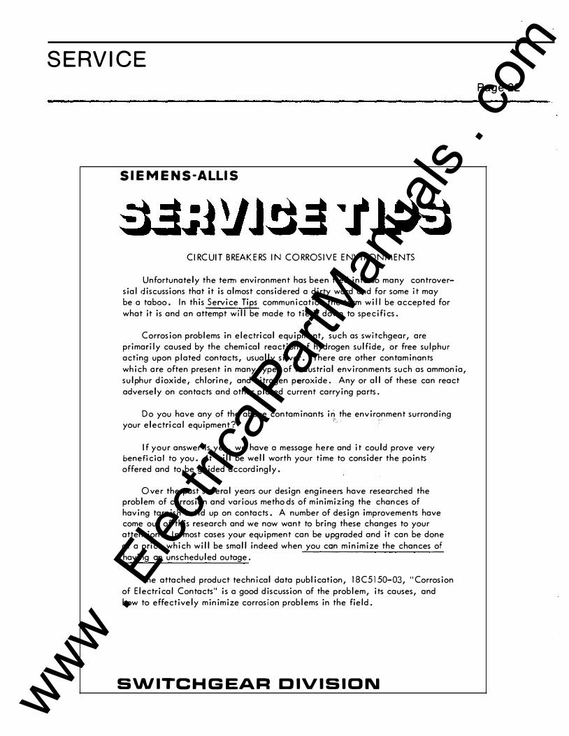
CI RCUIT BREAKE RS IN CO R R OSIVE ENVI R ON MENTS
Unfortunately the term environment has been tied into so many controversial discussions that it is almost considered o dirty word and for some it may be o taboo. In this Service Tips communication the term will be accepted for what it is and on attempt will be mode to tie it down to specifics.
Corrosion problems in electrical equipment, such as switchgear, ore primarily caused by the chemical reaction of hydrogen sulfide, or free sulphur acting upon plated contacts, usually silver. There ore other contaminants which ore often present in many types of industrial environments such as ammonia, sulphur dioxide, chlorine, and nitrogen peroxide. Any or all of these con react adversely on contacts and other plated current carrying ports.
Do you hove any of the above contaminants i� the environment surronding your electrical equipment?
,-, · · · ·
If your answer is yes, we hove o message here and it could prove very beneficial to you. It will be well worth your time to consider the points offered and to be guided accordingly.
O ver the post several years our design engineers hove researched the problem of corrosion and various metho ds of minimizing the chances of having tarnish build up on contacts. A number of design improvements hove come out of this research and we now wont to bring these changes to your attention. In most cases your equipment con be u pgraded and it con be done at o price which will be small indeed when you con minimize the chances of having on unscheduled outage.
The attached product technical data publication, 18C5150-03, "Corrosion of Electrical Contacts" is o good discussion of the problem, its causes, and how to effectively minimize corrosion problems in the field.
SWITCHGEAR DIVISION
Page 22
www . El
ectric
alPar
tMan
uals
. com

SERVICE
You will note that we now specify a special contact lubricant to protect contact surfaces from corrosive elements. This is in place of the graphite we formerly used. We ask that any Allis-Chalmers Switchgear instruction book which you have calling for graphite be corrected to call for the contact lubricant. In making this change you must also recognize and adhere to the contact pressures called for at the hinge joints under this improved lubrication system on all Siemens-Allis {formerly Allis-Chalmers) breakers 5kV through 15kV, air magnetic type.
Air Magnetic Breaker Class
5kV 6.9 thru 15kV
Pounds Pull On Blade
With Graphite
7-9 Lbs. 5-7 Lbs.
With Contact Lube
4-6 Lbs. 2-4 Lbs.
Be sure of your lubrication in the hinge joints before making a change.
See the attached lubrication chart 18X4841-03 for 5KV and 15KV breakers having Type SE-3, SE-4 or solenoid operators. For the latest design 5 15 operators the chart is included in the applicable instruction books. The chart for low voltage breakers which shows the latest style breaker is still typical of the areas w hich require care in lubrication.
For all older breakers (pre-1973) which are in corrosive environments and exhibiting potential problems we recommend replacing all current carrying ports with reconditioned, or new, components which ore plated and lubricated in accordance with our present practice. Replacement of only the parts which appear to be failing only defers the ultimate failure. In order to insure proper adherence to specifications the ports should be sent back to the factory for reprocessing. One method of hand I ing this rework program would be to buy sufficient new parts to rework two (2) or more breakers and the corresponding cubicle stationary contacts. Return ports removed which ore salvageable to the factory for re-processing. When re-processed parts are received, go on to the next 2 or 3 breakers and repeat the process until entire installation has been upgraded. In no case should graphite be used in the rebuilding process.
If you are now interested in upgrading your equipment we suggest you contact the local Siemens-Allis Sales Office in your area.
Attachment
R eprinted February, 1978 Page -2-
Page 23
www . El
ectric
alPar
tMan
uals
. com

SERVICE Page 24
SIEMENS-ALLIS
Switchgear Division product technical data CORROSION OF ELECTRICAL CONTACTS
INTRODUCTION Metal-clad and metal-enclosed switchgear is regularly applied in all types of industrial environments. Certain contaminants in the air can be very detrimental to reliable equipment performance if the appropriate precautions are not taken, both in the design of the switchgear and in its regular maintenance.
The principal problem areas are centered around the contact surfaces: breaker main contacts and hinge joints, and breaker/cubicle primary disconnect assemblies. These components are all heavy section copper normally plated with pure silver. Corrosion or mechanical damage to these contact surfaces can result in increased electrical resistance, overheating, and eventual failure.
CAUSES OF CORROSION The corrosion problems in switchgear are primarily caused
by the chemical reaction of hydrogen sulfide, or free sulfur, with the metal contact materials, usually silver. The result is the buildup of a tarnish film of silver sulfide. Other pollutants commonly present in industrial atmospheres may include ammonia (NH3) . sulfur dioxide. (S02), chlorine (CI) , and nitrogen peroxide (N02) - All of these can also adversely react with the contact materials to form corrosion compounds.
The severity rate of tarnishing, or corrosion, is further influenced by the concentration of the pollutant, the temperature of the materials, and the presence of moisture. Concentrations of the compounds mentioned above are currently being noted in the range of 500-1000 parts per billion in industrial atmospheres; in the case of sulfur the increase in concentrations in the past decade has been 4 orders of magnitude. Typical operating temperatures for switchgear contacts are in the range of 100 degC and have tended to increase in recent years with the advant of better electrical insulations. The presence of moisture in equipment is almost unavoidable; it allows the formation of a variety of acids which can attack the copper and silver contact materials.
EFFECTS ON SWITCHGEAR CONTACTS
The visible evidence of corrosion in switchgear is very easy to recognize; the silver tarnish on contacts is a dull gray or black coating over the usual bright silver surface. Many of the salts of copper which are likely to be formed exhibit the characteristic green color. Other metallic salts will show as white granular deposits.
Formation of tarnish on contact surfaces almost invariably increases the local contact electrical resistance, as most of the corrosion products, and tarnish films, are electrical insulators, or at ·best semi-conductors. The resulting increase in resistance causes localized heating in the region of the contact spot; this in turn increases the rate of corrosion leading to even greater losses.
As excessive temperatures are reached, the contact backup springs may lose their temper and relax, localized contact melting begins, and if the heat which is produced cannot be suitably dissipated thermal runaway occurs followed by complete destruction of the contact structures.
MINIMIZING CORROSION BY DESIGN In order to continually improve switchgear in the face of increasing concentrations of pollutants in the atmosphere, Siemens-Allis has continuously evaluated various materials and processes for use in critical contact designs. Recent efforts in this field have led to three basic design revisions affecting various components of the 600-volt, 5 kV, and 15 kV product lines:
Silver-plated contacts - All circuit breaker contact fingers are now electro-plated with a thick deposit (0.001 ") of silver applied under carefully controlled conditions to insure a dense, non-porous film. This applies to all primary disconnect fingers, main and hinge contact fingers on all circuit breakers. Many investigations have vertified that pure silver is still unexcelled in these high pressure, high current density applications. All the alternates fail to do the job: gold, tin, cadmium, nickel. The elimination of porosity in the plating prevents any corrosion of the underlying copper, and the thick film insures good life under conditions of mechanical abrasion on sliding contacts. www .
Elec
tricalP
artM
anua
ls . c
om
SERVICE
Back-up springs - To produce a wider margin of safety in primary disconnect assemblies, we have instituted the use of back-up springs made from 17 -7PH stainless steel in place of the traditional music wire or 18-8 stainless. Type 18-8 stainless, at 80 kpsi, exhibits a 9% loss of load at 290 degC; this compares to a 200 degC limit for music wire
·for the same loss of load. A significant further improvement is obtained with 17-7PH: only a 3.8% loss of load at 290 degC, 80 kpsi stress level.
Protection from tarnish - Considerable experimental research has established that protection of critical contact surfaces from corrosive elements is the most effective deterrent to problems. A good protective grease will not only shield surfaces from corrosive attack, but it will also increase the wear life of sliding contacts.
The choice of a grease suitable for the application must consider several important properties of the material. Ability to withstand operating temperatures (above 100 legC) without decomposition, chemical stability in the ex
,Jected atmospheres, electrically non-conducting, chemically neutral to silver and retention on vertical surfaces at high temperatures are all important considerations.
Siemens-Allis Electrical Contact Lubricant - After several years of reserach, investigation and test, Siemens-Allis has developed a contact lubricating material which fulfills all
the needs outlined above. This program included evalua-
Page 25
tions of 14 candidate materials, with evaluations for 28 days at 120 degC including: a) weight and color change; b) oil separation; c) evaporation; d) adhesion to glass; e) tarnish protection of silver against 5-20 ppm H2S. The finally selected material was successfully subjected to additional tests, all at elevated temperatures: a) thermal stability in air; b) thermal stability with H 2S; c) thermal stability of the total system including silver, grease, air, moisture, and H2S. As a result, the use of Siemens-Allis Electrical Contact Lubricant has been made a standard factory procedure on all main current-carrying contacts.
MINIMIZING CORROSION IN THE FIELD
There are two factors which are the keys to mm1m1zmg operating problems caused by contact corrosion:
Preventive maintenance - All main contact sliding surfaces and disconnect fingers should be inspected regularly , with a maximum interval between inspections of 12 months. In applications where it is known that duty is unusually severe, or corrosive elements are present, the inspection interval should be decreased accordingly.
Application of grease - At each maintenance inspection all of the old grease should be wiped off of the contacts and new lubricant applied to all sliding surfaces. Apply the material in a layer between 1/32" and 1/16" thick. Use only Siemens-Allis Electrical Contact Lubricant, part No. 15-171-370-002, available in 8 oz. tubes.
18C5150-03
www . El
ectric
alPar
tMan
uals
. com
LUBRICATION Low Voltage Air Magnetic Circuit Breakers
CIRCUIT BREAKER LUBRICATING INSTRUCTIONS
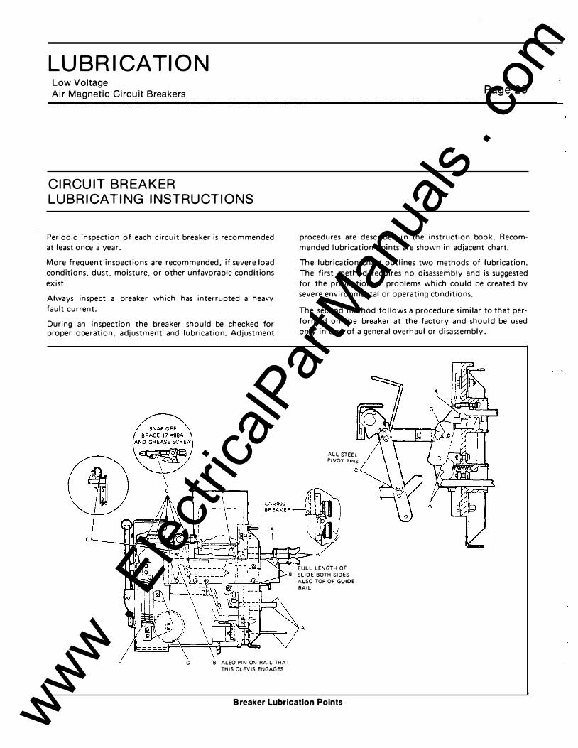
Periodic inspection of each circuit breaker is recommended at least once a year.
More frequent inspections are recommended, if severe load conditions. dust. moisture, or other unfavorable conditions exist.
Always inspect a breaker which has interrupted a heavy fault current.
During an inspection the breaker should be checked for proper operation, adjustment and lubrication. Adjustment
Page 26
procedures are described in the instruction book. Recommended lubrication points are shown in adjacent chart.
The lubrication chart outlines two methods of lubrication. The first method requires no disassembly and is suggested for the prevention of problems which could be created by severe environmental or operating conditions.
The second method follows a procedure similar to that performed on the breaker at the factory and should be used only in case of a general overhaul or disassembly .
ALL STEEL PIVOT PINS
FULL LENGTH OF 8 SLIDE BOTH SIDES
ALSO TOP OF GUIDE RAIL
C 8 ALSO PIN ON RAIL THAT THIS CLEVIS ENGAGES
B reaker Lubrication Points www . El
ectric
alPar
tMan
uals
. com

LUBRICATION Typical Lubrication Chart - L. V. B reakers Page 27
METHOD FOR CLEANIN G BEARINGS ON OLDER STYLE BREAKERS HAVING N EEDLE OR SLEEVE BEARINGS
Needle bearings are factory lubricated for life and should not require attention. However, the best of greases are affected by time and atmospheric conditions and may require service.
wash in alcohol, spin in light machine oil, drain and repack with Beacon P-325 grease. Caution: Needle bearings should not be removed from the retaining part.
To lubricate these bearings when parts are disassembled, the following procedure is recommended: Clean in solvent,
The sleeve bearings should be removed, washed in clean solvent, drained and dried thoroughly before lubricating with Beacon P-290.
Lubrication Chart
LUBRICATION (REQUIRES LUBRI- SUGGESTED LUBRICATION DISASSEMBLY) RECOMMENDED
CATION AT EVERY* OPERATIONS EVERY 5 YEARS OR ANY KEY PART DESCRIPTION OR EVERY SIX MONTHS COMPLETE OVERHAUL
A CONTACT ARM HINGE WIPE CLEAN AND APPLY A FILM OF SIEMENS-ALLIS ASSEMBLY. CONTACT LUBRICANT 15-171-370-002 IN LAYER 1/32" PRIMARY DISCONNECT
to 1 /16" THICK.
FINGERS, GROUNDING
I CONTACT.
SECONDARY DISCONNECT FINGERS.
B SLIDING SURFACES. LIGHT APPLICATION OF *MOL YCOTE 557*
c PIVOT PINS, ROTATI NG LIGHT APPLICATION OF PARTS SUCH AS DRIVE *MOL YCOTE PENELUBE* PINION, GEAR. 15-171-270-002.
D GROUND SURFACES SUCH WIPE CLEAN AND SPRAY AS LATCHES, ROLLERS, WITH *MOL YCOTE 557* PROPS, ETC. 15-171-270-001.
E ARCING CONTACTS. DO NOT LUBRICATE.
F SPRINGS. NO LUBRICATION REOUI RED.
G DRY PIVOT POl NTS. NO LUBRICATION REOUI RED .
. ubrication should be checked and renewed as follows:
LA-600 operations between lubrications 1750 LA-1600 operations between lubrications 500 LA-3000, LA-4000 operations between lubrications 250
WIPE CLEAN AND APPLY *MOL YCOTE 557* Ll BE RALLY.
REMOVE PINS OR BEARI NGS, CLEAN PER INSTRUCTIONS AND APPLY *BEACON P-290 .. 00-337-131-001.
WASH CLEAN A ND SPRAY WITH *MOL YCOTE 557* 15-171-270-001.
DO NOT LUBRICATE.
NO LUBRICATION REQUIRED.
18X5726-01 www . El
ectric
alPar
tMan
uals
. com

LUBRICATION 5 & 1 5 kV A ir Mag netic Circuit Breakers Page 28
CIRCUIT BREAKER W ITH SE-3 OR SE-4 OPERATOR LUBRICATING INSTRUCTIONS
Peri odic inspecti on of e a c h c i rcuit breaker is reco m
mended at l e a s t once a yea r .
More frequent inspec ti ons a r e rec o m m ended , if se
vere load c ondi ti ons , dust, m oistur e , or other un
favorable c onditions exi s t .
A lways inspect a bre aker which h a s interrupted a
heavy fault c ur rent.
During an inspect i on the breaker s hould be checked
for proper ope ration , adjust ment <:: nd lubnc ati on. Ad
justment procedures a r e des c r ibed m the instruction
METHOD FOR CLEANING BEARINGS
N eedle and rolle r bear i ngs a r e f a c: to ry l u br i c a te d for
life and s hould not requ i re a t t e n t i on . H owev e r , the
best of greases are affec ted bv t i me a nd a t m o s p h e r i c
cond iti ons and m a y req u i re s e rv i c e .
T o lubri cate t hese bearings w he n parts a re d i s a s s e m
bled, the fol lowing proc e d u r e is r ec o m me nded : C le a n
in solvent , was h in a l c o ho l , s pi n i n l i �ht m ac: h i ne o i l ,
book. Recom mended lubric ation points are s hown in
ad jacent c ha r t .
The lubri c ation c ha r t outlines two methods o f lubric a
t i on. The fi rst met hod requ i res no disasse mbly and
is suggested for the prevention of proble m s which
could be c reated by sev ere env i ron menta l or oper a ting
conditi ons .
The second method follows a pr oc ed u re s 1 m i la r to t ha t performed on the b reaker a t t he fa c to r y a nd s h ould
be used only 1n ca s e of a general ove r h a u l or d i s
assembl y .
drain a nd repack w i th Beacon P - J 2 5 g re a st> . C a u t i on: N eedle bear ings should not be re m oved fro m t hl· r e
taining part .
The s leeve bearings s hould be r e m o , e d , w a s he d i n
clean solvent , d r a ined and d r i ed t h o r o ug h l y bef o r e l u
bricating w i t h Beacon P-290.
www . El
ectric
alPar
tMan
uals
. com

LUBRICATION 5 & 1 5 kV Air Mag netic Circuit Breakers Page 29
Lubrication Chart (See Figure 1 through 5)
LUBR I� SUGGEST E D LUBR ICATION A LT E R NATE L U BR I CATION ( R E-
CATION AT E V E R Y 2000 OPERATIO NS Q U I R ES D I SASS E M B L Yl R ECOM·
K E Y PART D E S C R I P 1 10N OR O N C E E V E R Y Y E A R . M E N DE D A F T E R E V ERY 1 0 .000 OPE R .
A G R O U N D S U R FACES SUCH AS WIPE C LE A N A N D SPRAY WASH C L F: AN AND SPRAY WITH
LATC H E S , R O L L E RS, PROPS. ETC. WITH • MO L YCOTE 557 • • M O L YCOTE 5 5 7 "
1 5·1 7 1 ·270·001 . 1 5-1 7 1 ·270..()0 1 .
B NY LON S L E E V E B E A R I NGS, SUCH AS : NO L U B R I CAT I ON R E QU I R E D . NO LUBR I CATION R E QU I R E D.
TH E C ON TACT A R M H I N G E P I N .
c S L E E' V E B E A R I N GS A N D P I VOT P I NS, LIGHT APP L I CATION O F R EM O V E P I N S O R B E A R I NG S .
ROTAT I N G PARTS S U C H AS D R I V E •MOLYCOTE P EN E LU B E • C L E AN P E R I NSTRUCTIONS A N D
P I N ION , D R I V I N G CRANKS, WA L K I N G 1 5-1 7 1 -270..002. APPLY • B EACON P-290•
BEAM P I V OT P I N , S L I D E AND P I VOT 00-337-1 31 ..()01 .
P I N .
D S L I D I N G S U R F AC E S S UC H A S : TH E L I G H T APPL ICATI O N OF W I P E C L EA N A N D APPLY •MOL Y-
M A I N S O L E N O I D ARMATUR E . • M O L YCOTE 5 57 • . COTE 557 • L I B E R A L L Y.
E A I R PU F F E R C Y L I N DE R S . WIPE C L E A N A N D APPLY WASH CLEAN AND WET F E LT R I N G
TRANSFORM E R O I L I 3 IN TRANS F OR M E R O I L if 3.
TO F E LT.
F R O L L E R A N D N E E D L E B E A R I NGS. NO LUBR ICATI ON R E Q U I R E D. C L EAN P E R I NSTRUCTIONS A N D
R EPACK W I TH * BEACON P-325 • .
G DR Y f' I "0T PO I N TS . N O L U B R ICATION R EQ U I R E D . N O LUBR ICATION R E QU I R E D .
H PR I M A R Y D I SCON N ECT F I N G E R S , WI PE C L EA N AND APPLY A FILM O F S I EMENS-ALLIS
GROU N D I N G CONTACT. CO NTACT L U BRICANT 1 5- 1 7 1 ·370-002.
I ARC I N G CONTACTS . DO NOT L U BR I CAT E . D O N OT LUBR I CATE
J CONTACT A R M H I N G E ASS EM B L Y , !::JL . V E R WI PE CLEAN AN D APPLY A F I L M O F SIEMENS-ALLIS
WAS H E R B E TWE E N BUSH I N G AND T H E CO NTACT L U BRICANT 1 5· 1 7 1 -370-002. CONTACT A R M .
K CHARG I N G SPR I NGS & NO LUBR ICATION R E QU I R E D W I P E C LE A N AND COAT WITH
SPR I N G R E TA I N E R S O F B E ACON P-325.
1 8X4841 ..03
www . El
ectric
alPar
tMan
uals
. com

LUBRICATION
CONTACT F INGER./;;\ ASSEMB.:f �y
+ '-IV'-+--� . . - ,
;. 4 -- - - ;
n I I I ! I ! :LJ
! Jr--------.:..� I I -9IF=- i-
� . -i n
fl I / I I
I ; I /
- • ·-=--· I \ CONTACTS ----:- \..-/
, . ;_·� · - ..
�----��::::::::� ---,_ FOOT lEVER --�··
( INTERLOCK RELEA:£)
\._ E�:,.PUF"F"ER
O INTERLOCK PLU'a:R
Figure 1 . Typical 5 kV Breaker
I : :o l ' I
Page 30
www . El
ectric
alPar
tMan
uals
. com

LUBRICATION
S H U T T E R G UIDE G
GROUND CONTACT
I
0
-e-
l, , , ; :
�·
Page 31
----, \ I � �. . ) C O N TA C T fiNG E R
ASSE MBLY 'l --) !PRIMA R Y )
r ---/; I I _@PIN
�
Figure 2. Typical 1 5 kV Breaker
www . El
ectric
alPar
tMan
uals
. com

LUBRICATION
SPUR G E A R .f?\�G ·
D R I V I NG C \ CRANK B E A R I N G
P I N
�� ' '
\
' '
\
@
rS';-P I N r F
' I ff\ , I v \ + TOGGLE (.9" ROLL
f!\ L ATCH "0 ROLL
Figure 3. Stored Energy Operator for 5 kV Breaker
Page 32
fF" PIN
F P I N
www . El
ectric
alPar
tMan
uals
. com

LUBRICATION
Page 33
TRIP P LUNGER
Figure 4. Stored E nergy Operator for 15 kV B reaker
www . El
ectric
alPar
tMan
uals
. com

LUBRICATION
A RMATURE® \
\
A TOGGLE ROLL
�N \
r PIN
Page 34
�--TH----- --(r)- P I N " --"
1 i I
cb-PIN
Figure 5. Typical Solenoid Operator AaHmbly for 5 & 25 kV Breakers
www . El
ectric
alPar
tMan
uals
. com

LUBRICATION 5 & 1 5 kV Air M agnetic Circuit B reakers
with M odel 51 5 O perators
BASIC REQUIREMENTS
•
Periodic m spection of e a c h c 1 rc u 1 t breaker IS recomme nded at least once a yea r
M ore f requent i n spect i o n s a re recom me nded. 1f severe load co n d 1 t 1ons. d u s t .
mo1sture. or other u nfavorable cond1t 1ons exist
A lways i nspect a breaker w h i c h h a s mterrupted a heavy f a u l t cu rrent
D u r mg an i n spect 1on the breaker s h o u ld be checked for p roper opera t 1 o n . ad
j U Stment a n d l ubricat ion Adjustment proced u res are descn bed m t h e 1 n str u c
t 1on boo k . R ecommended l ubncat1on pomts a re s h own m adjacent chart
The l u brication c h a rt o u t l i nes two met hods of l ubr icat 1 o n . The f t rst method re
q u i res n o d isa ssembly a nd i s suggested for the prevent 1on of problems wh 1 c h
could be created b y severe envi ron menta l or operatmg con d 1 t 1 o n s
The second method fol lows a proced ure s i m i l a r to that perfor med on the brea k
er at t h e factory a n d s h o u l d b e u s e d o n l y i n case o f a genera l ove r ha u l o r
d isassembly_
Page 35
METHOD FOR CLEANING BEARINGS ON OLDER STYLE BREAKERS HAVIN G NEED LE OR SLEEVE BEARINGS
N eedle bear i ngs a re factory l ubricated for l i fe a nd s h o u l d n ot req u t re attent 1 o n
H owever, the best o f g reases a re affected b y t i m e a nd a t mosphenc con d 1 t 1 o n s
a n d may requ i re service.
To lubricate these bearings w h e n p a rts a re d i sassembled, the fol lowing procedure is recomm e n d ed: Clean in solvent, wash i n alcohol , spin in l ight m ach i n e oi l , dra i n a n d repack with Beacon P-325 g rease. Ca ution: Needle bearings should not b e removed from the retaining pa rt.
The sleeve bearings s h o u l d be removed. washed in clean solvent, d ra i n e d a n d d ried thoroug h ly before l ubricating with Beacon P-290.
www . El
ectric
alPar
tMan
uals
. com

LUBRICATION 5 & 1 5 kV Air Magnetic Circuit B reakers
with M odel 51 5 Operators
SHUTTER G U I D E @
G ROUND fu\ CONTACT �
"
GUIDE @
Lubrication Points on Breaker
Page 36
@ FOOT LEVER ( I NTERLOCK R ELEASE)
www . El
ectric
alPar
tMan
uals
. com
LUBRICATION 5 & 1 5 kV Air Magnetic C i rcuit Breakers with Model 51 5 O perators
r--
1
SlOE V I E W "A"
Page 37
@
FRONT V I EW "A"
VIEW "C"
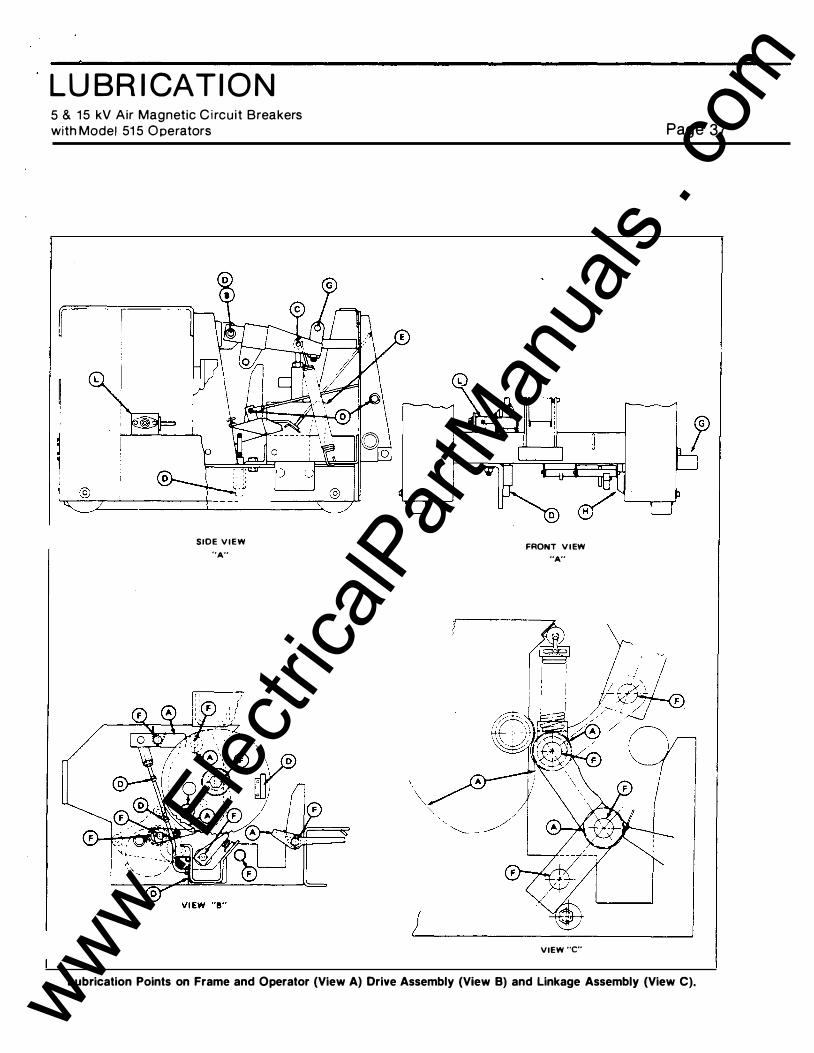
Lubrication Points on Frame and Operator (View A) Drive Assembly (View B) and Linkage Assembly (View C). www . El
ectric
alPar
tMan
uals
. com

-
LUB RICATION 5 & 1 5 kV Air Mag netic Circuit Breakers
with M odel 5 1 5 O perators Page 38
Lubrication Chart
L U B R I - j S U G G E S T E D L U B R I C A T I O N A L T E R N A T E L U BR I C A T I O N ( R E-
C A T I O N .
AT E V E R Y 2000 OP E R AT I O N S QU I R ES D I SASS E M B L Y ) R EC OM-
K E Y PAR r DESC R I P T I O N O R O N C E E V E R Y Y E A R . M E N D E D A F T E R E V E R Y 1 0 ,000 OP E R .
A G R O U N D S U R F AC ES S U C H AS W I P E C L E A N A N D SPRAY WAS H C L EAN AND S P R A Y W I T H
L ATC H ES . R O L L E R S . P R Of'S. E T C . W I T H • M O L Y C O T E 5 5 7 • • M O L YCOTE 5 5 7 •
1 5 -1 7 1 -270-00 1 . 1 5-1 7 1 ·270-{)01 .
B N Y LON S L E E V E B E A R I N GS, S U C H A S : N O L U B R I C A T I ON R E QU I R E D. NO L U BR I CA T I O N R E QU I R E D.
TH E CON !"ACT A R M H I N G E P I N .
c S L E E V E B E A R I NGS A N D P I V OT P I NS, L I G H T A PP L I C A T I ON OF R E M O V E P I NS O R B E A R I N G S .
R O TAT I N G P A R TS S U C H AS D R I V E • M O L YCOTE P E N E L U B E • C L E A N P E R I NS T R U C T I O N S AN D
P I N ; O N , D R I V I N G C R A N K S , S L I D E 1 5-1 7 1 -270-002- APP L Y • B EACON P-290•
A N D P I VOT P I N S . 00-337-1 3 1 -{)01 .
-
u S L I D I N G SUR F A C E S . L I G H T APP L I C A T I O N OF WIPE C L EA N AND APPLY •MOL Y-
• M O L YCOTE 557 • COTE 557 • L I B E R A L L Y .
E A I R P U F F E R C Y L I N D E R S . W I P E C L E A N A N D A P P L Y WASH C L E A N A N D WET F E LT R I N G
T R A N S FO R M E R O I L I 3 IN T R A N S F O R M E R O I L # 3 .
TO F E LT . 1 5 - 1 7 1 - 7 29·00 1
F R O L L E R A N D N E E D L E B E A R I N G S . N O L U BR I C A T I O N R E QU I R E D . C L E A N P E R I N S T R U CT I O N S A N D
R E PACK W I T H • BEACO N P-325 • .
G D R Y � 1 "11T P O I NTS . NO L U BR I C A T I O N R EQU I R E D N O L U B R I C A T I O N R E QU I R E D .
H P R I M A R Y A N D SECON D A R Y D I SCON N ECT WIPE CLEAN AND APPLY A FILM O F S I E M E NS-ALL I S
F I N G E R S , A R C I NG C O N T A C T H I N G E . CONTACT L U BRICANT 1 5- 1 7 1 -370-002.
G R O U N D I NG CONTACT A N D A U X .
SWI TCH CONTACTS.
I A R C I N G C O N TACTS . DO N OT L U B R I CATE . DO N OT L U B R I C A T E
J D I S C O N N E CT A R M H I N G E J O I N T S I LV E R WI PE C L EA N A N D APPLY A F I L M O F SIEMENS-ALLIS
WASHER B E TWE E N B U S H I N G AND THE CO NTACT L U BRICANT 1 5- 1 7 1 -370·002.
C O N TACT A R M .
K C H A R G I N G S PR I NG S & N O L U BR ICA T I ON R EQU I R E D WIPE C L E AN A N D COAT W I T H
S P R I N G R ETA I N E RS OF •B E A C O N P-325 . •
L M A N U A L C H A R G I N G B EV E L G E AR R EM O V E SNAP ON C O V E R & R E M O V E S N A P ON C O V E R & COAT
T R A I N , F B & F C S E R I E S O N LY . C O.II. r T E E TH L I G H T L Y W I T H T E ET H L I G HT L Y W I T H • B E A C O N
• B E A C O N P-325 . • P-325 . • 1 5 -337-1 3 1 -001
M A R C I N G CONTACT H I NG E WIPE CLEA N AND APPLY A FILM O F S I EM E NS-ALLIS
ASS E M B L Y _ CONTACT LUBRICANT 1 5- 1 7 1 -370·002.
www . El
ectric
alPar
tMan
uals
. com

LUBRICATION 34.5 kV VV-1 500 Vacuum C i rc u it B reaker
CIRCUIT B REAKER LUB RICATING INSTRUCTIONS
Periodic inspection of each c ircuit breaker is reco m mended at least once a year.
More frequent inspections are recommended, if severe load
conditions, dust, moisture, or other unfavorable conditions
exist.
Always inspect a breaker which has interrupted a heavy
fault current.
D uring an inspection the breaker should be checked for
proper operation, adjustment and lubrication. Adjustment
Page 39
procedures are described in the instruction book. Recom
mended l u brication points are shown in adjacent chart.
The l u brication ch art o ut l i ne s two methods of l u brication .
The fi rst method requires no disassembly and is suggested
for the prevention of problems which could be created by severe environmental or operating cnnditions.
The second method fol lows a procedu re s imi lar to that per
formed on the breaker at the factory and shoul d be used
only in case of a general overhaul or disassembly.
METHOD FOR CLEANING BEARINGS ON OLDER STYLE BREAKERS �AVING NEEDLE OR SLEEVE BEARINGS.
Needle beari n gs are factory l u bricated for l ife and sho uld
not require attention. However, the best of greases are affected by t ime and atmospheric conditions and may re
quire service.
To lubricate these beari ngs when parts are disassembled, the following procedure is reco m mended : Clean in solvent,
0" ' '"'" ' :. t o ·'· ' ' ' b
wash in alcohol, spin in l ight mach ine oi l , drain and repack with Beacon P-325 grease. Caution: Needle bearings should not be remo ved from the retaining part. The sleeve bearings should be removed, washed in clean solvent, dra ined and dried thorough l-y before l u bricating
with Beacon P-290.
� -� A l l 8fARH\(,$
AND PI 'I,$
�I I
0 /
0
1"0$10F 0� T � E B�A><E 6Af'>O
0
d
-
0
Lubrication Points on Truck Frame Assembly (Plan View) VV-1 500 Vacuum Circuit Breaker www . El
ectric
alPar
tMan
uals
. com

LUBRICATION
Page 40
Figure 30. Lubrication Chart
LUBRI- SUGGESTED LUBR ICATION ALTE RNATE LUBR ICATION ( R E-CATION AT EVERY 1 ,000 OPERATIONS QUI R ES DISASSEMBL Yl R ECOM-KEY PART D ESCR IPTION OR ONCE EVERY YEAR MENDED AFTER EVERY 5,000 OPER_
A G R O U N D SUR F A C E S SUCH AS W I P E C L E A N A N D SPRAY WASH C LE A N AND S P R A Y WITH
LATC H ES , R O L L E R S , PR OPS, ETC. WITH *M O L YCOTE 557 * * M O L YCOTE 557 *
1 5-1 7 1 -270-001 . 1 5-1 7 1 -270-001 .
B S L E E V E B EA R I N G S A N D P I VOT P I NS, LIGHT A P P L I C ATION O F R E MOVE P I N S O R B E A R I N GS ,
R OTAT I N G PARTS SUCH A S B E L L * M O LYCOT E P E N E L U B E * C L E A N P E R I NSTR UCTI ONS AN D
C R A N KS, D R I V E B A R . 1 5- 1 7 1 -270-002. APPLY * B EACON P-290*
00-337-1 3 1 -001 .
c S L I D I N G S U R FACES L I G HT A P P L I C ATION O F W I P E C L EA N A N D A P P L Y * M O L Y -
* M O L Y C O T E 5 5 7 • . COTE 557* L I B E R A L LY .
D S L I D I N G P A R TS AT VACUUM L I G H T APP LICATION O F L I G HT APP L I C A T I O N O F
I N T E R R U PTE R . * B EACON P-325* . * B EACON P-32 5 * .
E R O L L E R A N D N EE D L E B E A R I N GS . N O LUBR ICATION R E Q U I R E D . C L E A N P E R I N STRUCTIONS A N D
R EPAC K WITH * B EACON P-325 * .
F WH E E LS , SHA FTS, D R I V E B LOCKS.
B E A CON P-290. BE ACON P-290. SPR I N G R ETA I N E R
G P R I M A R Y A N D S E C O N DARY DISCONN ECT W I P E C L E A N AND A P P L Y A T H I N F I L M O F A L L I S-CHA L M E R S
F I N G E R S . GRO U N D I N G CONTACT A N D CONTACT L U B R I CANT 1 5- 1 7 1 -370-002.
A U X I L I A R Y SWITC H CONTACTS.
H C H A R G I N G SPR I N GS A N D S P R I N G NO LUBR I C ATION R E Q U I R E D . WIPE C L E A N A N D C O A T W ITH
R E TA I N E R S . * B EACON P-325 * .
J R A C K I N G S C R E W C O A T OF L I G H T G R A D E O I L . :1: 5 H Y D R A U L I C F L U I D .
www . El
ectric
alPar
tMan
uals
. com
LUBRICATION
Page 41
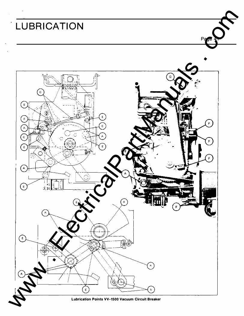
Lubrication Points VV-1500 Vacuum Circuit Breaker www . El
ectric
alPar
tMan
uals
. com

GROUN D AN D TEST DEVICES 5 and 1 5 k V H orizontal Metal-Clad S witchgear
SIMPLE TYPE TEST DEVICE
Inserted into the circuit breaker c ubicle, the test device is used for phasing out and potential test i ng of l i ne and
bus c ircuits. This device is furn ished with either six studs or th ree i nterchangeable studs which can be used
in e ither bus or l i ne positio n . The studs termi nate with i n
P H A S E B A R R I E R S T O P CO V E R S '
L I N E
P R I M A R Y
C O N T A C T
F I N G E R S
Page 42
the u nit. Access to the stud term i nals are th rough
i nsu lati ng doors. A ground bar on the front of the u n it
base al lows connection of g round ties for gro u nd i ng
dead bus or feeder circu its for maintenance protecti on.
C A T CH P R O V I D E D T O H O L D D O O R I N O P E N
,........,------------::..,; P OS I T I ON
, , ·\ · ! DOOR S W I N G �br�· o e "'��,o,'•m f..--------�.....,-l 'l A C C E S S ,•[! T O S T U D ) � I
H O R I Z O N T A L
B A R R I E R S
P R O V I S I ON S
F O R
P A D L O C K ( ��� O OO R SW ' " ' �� O F 1 80°
,...-'----l,,-------'1�
P R O V I S I O N F O R
L l F T I N G
- - I
5 kV Simple Type Test Device
I N T E R L O C K
R E L E A S E
F O O T L E V E R
www . El
ectric
alPar
tMan
uals
. com

GROUN D AN D TEST DEVICES 5 and 1 5 kV Horizontal D rawout Metal-Clad Switchgear
T O P P L A T E S
- - - - P R O V I SION FOR
L I F T I N G
Page 43
C A T C H P R O V I D E D TO H O L D
D O O R I N O P E N P O S I T I ON
1 /
G R OU N D BAR
I N T E R LOCK
R E L E A SE
FOOT L E V E R
1 5 kV Simple Type Test Device
GROUND & TEST DEVICE (ELECTRICALLY OPERATED )
Th e �round and test dev ice c ontains power-operated grounding conta cts for safe ly grounding e ither the I ine or bus. Th e power for grounding the contacts i s
supplied by a stored energy operator identical to a c ircuit breaker operator. It inc ludes manually oper"l.ted sele ctor switch c ontacts for l ine grounding or .mgrounded test c onnections. It also provides test ports and is interlocked to assure maximum safety w ith conve n i e n c e of use in any test j un c t ion.
The selector switch is manually operated and can
be operated only out of the cubicle. The power-operated
ground switch is electrically closed from a remote push
button station at the end of a 30-foot cable.
The unit is nonn ally opened manually by unlocking
the trip latch and pushing a release lever. (Optional
electric tripping can be furnished. ) Closing power is
obtamed through the cubicle secondary contacts (a
www . El
ectric
alPar
tMan
uals
. com

GROUN D AN D TEST DEVICES 5 and 1 5 k V H orizontal D rawout
M etal-Clad Switchgear
separate power and conhol source is available as an
option). The remote pushbutton station has two buttons
in series to reduce possibility of accidental operation.
Two sets of test ports , located on the front panel, pro
vide easy access to the primary studs. The upper set of three ports is direct-connected to the lower primary studs and the lower set is connected to the selector
switch. This arrangement permits connection to bus or
line, depending on switch position. Sliding doors over the ports isolate the primary studs not used in testing.
Six test j acks or probes are provided to fit into the test
ports and furnish easy connection of test equipment.
The probe lug is si zed to take up to #2 wire. Three conditions of test port access are provided:
a. Line test or grounding - With the selector switch in line position, the selector ports can be exposed
Page 44
giving access to the line. But test ports are locked closed.
b. Bus test or groun ding - With the selector switch in the bus position, the selector ports can be ex-· posed giving access to the bus. Bus test ports are locked closed.
c . Un grounded tests - With the selector switch in line position, and the ground switch locked open by transfer of the key from the interlock (at the b ack left of the operator) to the panel studs interlock, all six ports can be opened. (If the key is not inserted in the panel slide interlock, after withdrawal from the operator interlock, access is through the selector
ports only and grounding is prohibited.) The selector
ports can also be padlocked closed at any time.
www . El
ectric
alPar
tMan
uals
. com

S E L E C T O R SWITCH H A N D L E M U S T B E R E MOV E D T O P E R M I T I N S E R T I N G D E V I C E I N T O C U B I C L E ( H A N D L E I S R E MOV A B L E ON L Y I N POSIT I ON SHOWN). -;]
(II
C O N T ROL C A B L E S T O R A G E R � L - · -Y "/·
T O P C OV E R�� I I � T R A N S P A R E N T BAR R I E R S '::--i " L -:1 • ·
< E N A B L E V I S U A L I N S P E C T I ON , , ·ffiJ. _ , 1-----flt 1 �. {.tl � OF S E L E C T OR SWI TCH & �· _-
:II STUD I - . g G R OU N D I N G SW I T CH !�-� 1
Q. � . I
I ��}:_:�t_-_ -1 Cll (II -0 Cll < r:r Cll -m
T E ST P R O B E
c =1]
INSU L A T E D T U B E
���;�I N A L F O R CU STOME R T E S T L E A D C ON N E C T I ON
O P E R AT I N G
I I' l G lt\1,.,•
I N S T R U C T I ON S 1 1' , I 1 � • '
K I R K IN T E R LO C K K E Y R E MOV E D W I T H BOL T
[ G R OU N D BUS -::!. n !!. -< 0 "D Cll ii1 [ --
K E Y IN T E R L O C K TO B R E A K C L O S I N G C I R C U I T O N K E Y R E MOV A L .
T R I P & L A T C H LOC K I N G D E V I C E
���\R"oo,u:�;o [ J
G R OU N D I N G SWITCH P O S I T I O N I N D I CA T O R
� L A TCH LOCK CU T·OU T
::t:P== ===1001 ;-.:__� C LO S I N G P U SH B U T T ON S T A T I ON (2 C ON T AC T S IN S E R I E S) A T T ACH E D TO A 30 F T . C ON T R OL C A B L E
SW I T CH T O P R E V E N T C LO S I N G G R OUN D I N G SWITCH WH E N L A T C H NOT LO C K E D C L O S E D .
� (]I CD Ill - :::J � a. I 0 ...... iii" (]I Q. A
(/) < :E I -· 0 C) ::::!. � N (Q O CD :::J Ill .... �
"0 s:»
(Q CD � 01
0 @ :E 0 c -
G) :D 0 c z 0 )> z 0 -I m en -I 0 m < -() m en
www . El
ectric
alPar
tMan
uals
. com

... (11 � < Ci) ... 0 c ::J Q, Ill ::J Q, -t � � c � c;· � ...... m iD n -... c;· !!!. -< 0 � ; iD Q, ......
ST L E A D CON N E C T I ON ::iJ:t==:=y� f S E L E CTOR SWITCH H A N D L E MUST
�ERMINAL FOR CUSTOM E R S
INSU L A T E D T U B E CLOSING PUSH BUTTON ST A T I ON BE R E MO V E D TO P E RM I T I N S E R T IN G C U B I C L E PHASE (2 CON TACTS IN S E R I ES) D E V I C E INTO C U B I C L E . � I V I D E R T E ST P R O B E A T TACHED T O A 30 F T . CON T R O L C A B L E .
\ �
.. 1f - � i! ,I T O P C OV E R S '::lh--T_.:/ li t n fUl � fU] �
T RA N S PA R E N T BAR R I E R S E N A B L E V I SU A L I N S P E C T ION I � I <7' IJf� OF S E L E C T O R SWITCH & ""'- I I 7 · , 1. •
G ROUNDING SWITCH .
S E L E C T O R SWITCH
STUD
' II II Jl : : 1! I t I
Ll I <I ' ' - - - - - - ·!���-;;.-;;.-.�� =� : - - - - - - - - 1= =-== = -,:=--:� - ..1
STO R E D E N E RG Y CLOSING D E VI C E
K E Y I N T E R L O C K TO
B R E A K C LOSING C I RC U I T ON K E Y R EMOVAL .
I 'I I II ' ' ... ., tl
K I R K I N T E R LOCK·KEY R E MOV E D WITH BOLT
E X T EN D E D .
B U S T E S T PORTS
(ALWAYS CONN E C T E D T O ' ' BUS" BUSHINGS) LOCKED CLOSED WHEN S E L E CTOR SWITCH I S
IN "BUS" P O S I T I O N .
GROUN D I N G SWITCH
GROUND BUS
LATCH LOC K C U T ·OUT
SWI T C H TO P R E V E N T
CLOSING GROUNDING
SWITCH WHEN L A TCH I S
N O T LOC K E D CLOSE D .
T R I P & L A T C H LOC K I N G D EV I C E .
_.;
!•I, , . ,. • •• ' o L : :�ti" ffl - - -I:{UE� '£." �� l '' 0' fjl- _ cr..::.--.::' .. _..., i� 1"f ,_.; (I � � i� _.. �'
r , , ! I "
NAME P L A T E
O P E R A T I N G I N S T R U C T IO N S
S E L E C TO R SWITCH
POSIT ION INDICATOR
S L I DING T E S T P O R T COV E R
P R OV I SIONS T O PADLOCK T E S T P O R T S C LOSE D .
S E L E C TOR P O R T S
( A L W A Y S CON N E C T E D
T O H I N G E J O I N T O F
SE L E C T OR SWITCH).
GROUNDING SWITCH POS I T I ON I N D IC A T OR
I N T E R LOCK R E LE A S E F OOT L E V E R
I
I
I
I
I
I
5: 01 (!) I» - :J e!.. c.. I 0 ...... - 01 1» 7\ c.. < � I -· 0 - ..... 0 -· ::r N <0 0 (!) :J s:u -...., �
-u Dl
<0 (1) � m
0 ...., I» ::!:: 0 c .....
G) :0 0 c z 0 )> z 0 -I m en -I 0 m < -
0 m en
www . El
ectric
alPar
tMan
uals
. com

..
/
www . El
ectric
alPar
tMan
uals
. com

S IE M E NS - ALLIS
1 0/81 3M
Siemens-A l l i s , I n c. Switc hgear Division P.O. Box 29503 Raleig h , NC 27626
(9 1 9) 365-6660
P R INTED IN U .S.A. www . El
ectric
alPar
tMan
uals
. com