switching, stopping, positioning - assisdriveassisdrive.com/catalogos/keb/catalogo_combinorm.pdf ·...
TRANSCRIPT
GB

All our efforts are directed towards the development, production and application of electromagnetic tech-nology throughout our extensive range of brakes and clutches.The functions, starting, stopping, positioning and safe holding of moving axes in machines and plant callfor reliably designed and safely functioning components. With our advanced manufacturing techniques weare able to produce high quality, high-grade products, and through our continued investment we now havemanufacturing plants worldwide. We have the ability to produce high volume stock parts or ones that aretailored specifically to your requirements.
KEB Japan
KEB China
Steel processing
Dispatch coil production
Assembly
Steel processing
More than 30 years experience in thefield of Electromagnetic technology
KEB Germany
KEB America
MAG
NETT
ECHN
IQUE

COMBINORM K
COMBISTOP H
COMBISTOP N
COMBISTOP D
COMBISTOP T
COMBIPERM P1 COMBIPERM P1
COMBINORM C
COMBINORM B
COMBITRON 91
COMBIBOX
COMBITRON 92
COMBITRON 94
COMBITRON 98
COMBIPERM 22
POWER SUPPLY / SWITCHGEAR
SWITCHING, STOPPING, POSITIONING
Safe braking and holding
COMBISTOP
Electromagnetically actuated dual-surface springapplied DC brakes for dry operation.… starting from page 4
COMBIPERM
Permanent magnet fail-safe brakesand clutches for dry operation.… starting from page 16
COMBINORM
electromagnetic-actuated open-circuit operatedclutches and brakes without slip rings.… starting from page 22
COMBIBOX
a ready to be installed electromagnetic-actuated clutch-brake-module… starting from page 36
COMBITRON
DC-supply from the alternating voltage supply system andelectronic switches for electromagnetic clutches and brakes.… starting from page 44
CO
MB
ISTO
P
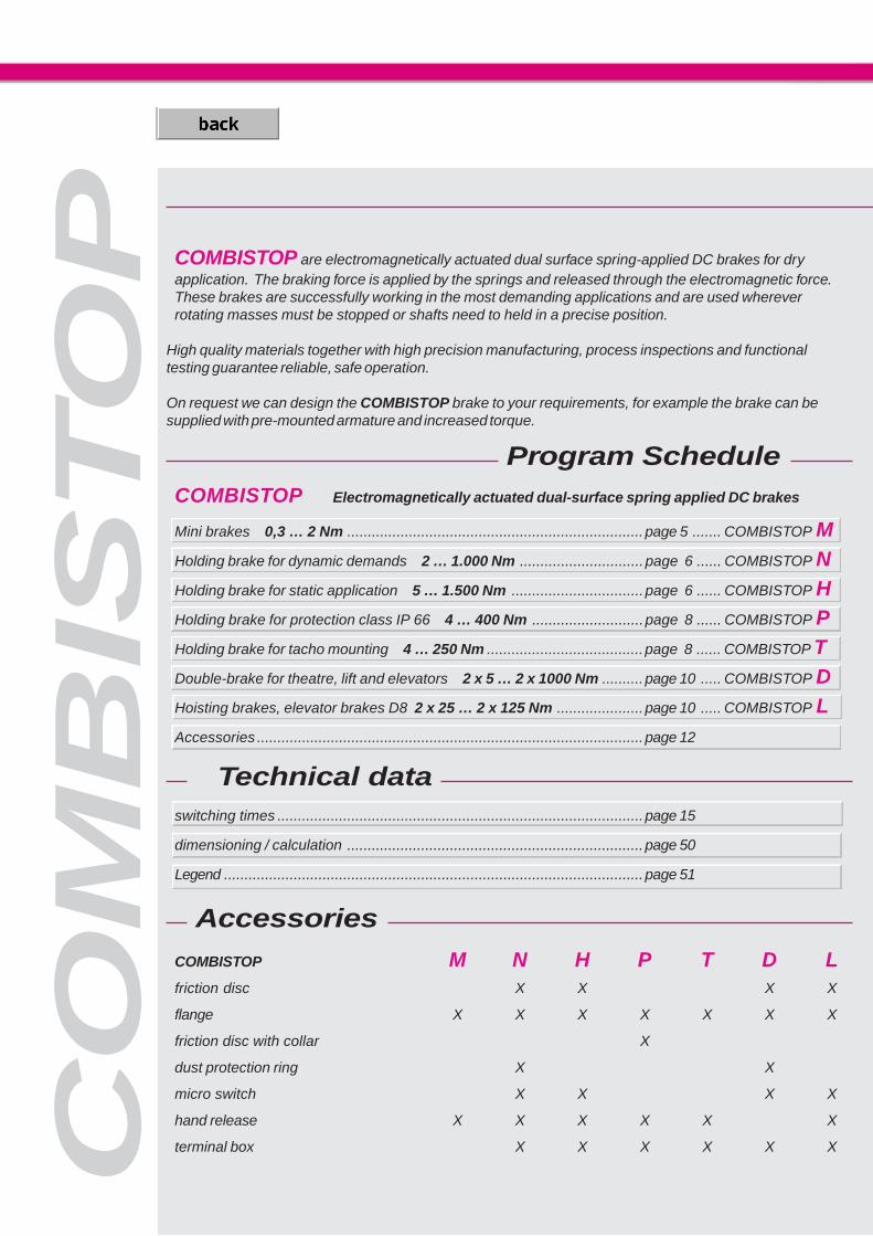
COMBISTOP Electromagnetically actuated dual-surface spring applied DC brakes
Mini brakes 0,3 … 2 Nm ........................................................................page 5 ....... COMBISTOP MHolding brake for dynamic demands 2 … 1.000 Nm ..............................page 6 ...... COMBISTOP NHolding brake for static application 5 … 1.500 Nm ................................page 6 ...... COMBISTOP HHolding brake for protection class IP 66 4 … 400 Nm ...........................page 8 ...... COMBISTOP PHolding brake for tacho mounting 4 … 250 Nm ......................................page 8 ...... COMBISTOP TDouble-brake for theatre, lift and elevators 2 x 5 … 2 x 1000 Nm ..........page 10 ..... COMBISTOP DHoisting brakes, elevator brakes D8 2 x 25 … 2 x 125 Nm .....................page 10 ..... COMBISTOP LAccessories ..............................................................................................page 12
Accessories
COMBISTOP M N H P T D Lfriction disc X X X X
flange X X X X X X X
friction disc with collar X
dust protection ring X X
micro switch X X X X
hand release X X X X X X
terminal box X X X X X X
COMBISTOP are electromagnetically actuated dual surface spring-applied DC brakes for dryapplication. The braking force is applied by the springs and released through the electromagnetic force.These brakes are successfully working in the most demanding applications and are used whereverrotating masses must be stopped or shafts need to held in a precise position.
High quality materials together with high precision manufacturing, process inspections and functionaltesting guarantee reliable, safe operation.
On request we can design the COMBISTOP brake to your requirements, for example the brake can besupplied with pre-mounted armature and increased torque.
Technical dataswitching times .........................................................................................page 15
dimensioning / calculation ........................................................................page 50
Legend ......................................................................................................page 51
Program Schedule
5
COMBISTOP M
����
�
�
�
���� ���
��������
� �
�
���
�
�
�
������� ���
����� �
�
���
���
�
�
�
� �� ��
�
�
�
��������
�����
�
�
�
�
���
���
���
���
���
���
���
CO
MB
IST
OP
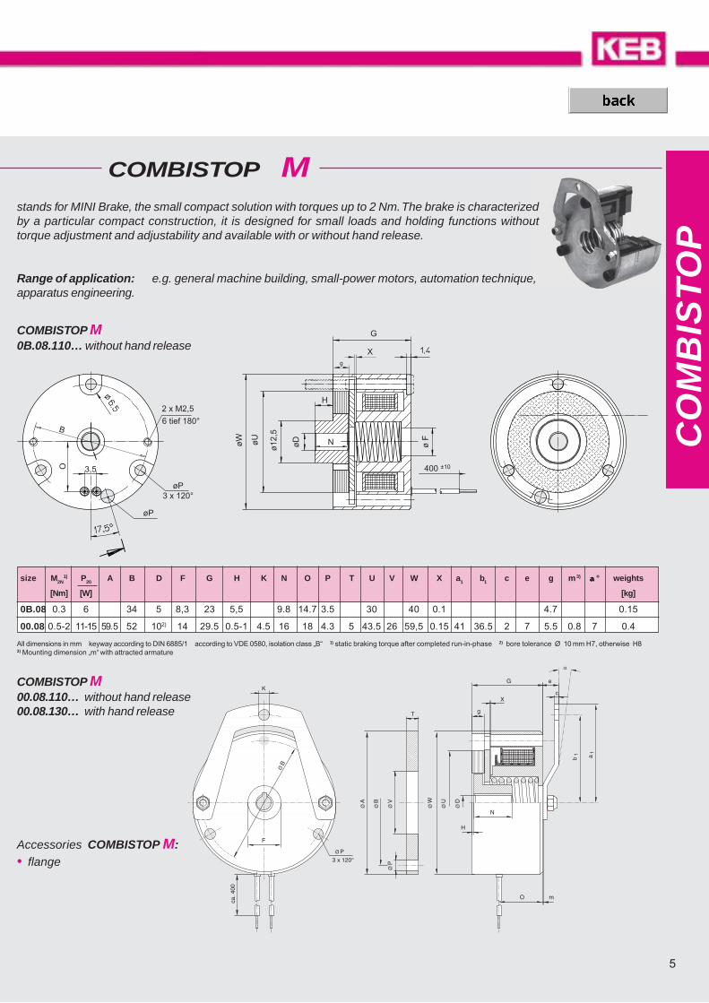
stands for MINI Brake, the small compact solution with torques up to 2 Nm. The brake is characterizedby a particular compact construction, it is designed for small loads and holding functions withouttorque adjustment and adjustability and available with or without hand release.
size M2N1) P20 A B D F G H K N O P T U V W X a1 b1 c e g m3) aaaaa ° weights
[Nm] [W] [kg]
0B.08 0.3 6 34 5 8,3 23 5,5 9.8 14.7 3.5 30 40 0.1 4.7 0.15
00.08 0.5-2 11-15 59.5 52 102) 14 29.5 0.5-1 4.5 16 18 4.3 5 43.5 26 59,5 0.15 41 36.5 2 7 5.5 0.8 7 0.4
All dimensions in mm keyway according to DIN 6885/1 according to VDE 0580, isolation class „B“ 1) static braking torque after completed run-in-phase 2) bore tolerance Ø 10 mm H7, otherwise H83) Mounting dimension „m“ with attracted armature
COMBISTOP M0B.08.110… without hand release
COMBISTOP M00.08.110… without hand release00.08.130… with hand release
Accessories COMBISTOP M:• flange
Range of application: e.g. general machine building, small-power motors, automation technique,apparatus engineering.
���
�
���
��� ���
�����!
��"��#� �
�
$
��
�
� #� � ���
�� ����
�%��
���
CO
MB
ISTO
P
V DC, Ø D ?
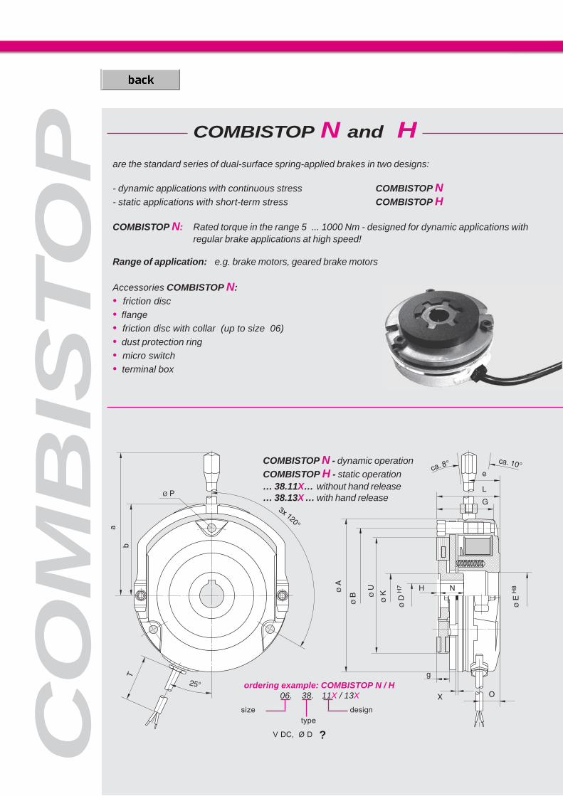
are the standard series of dual-surface spring-applied brakes in two designs:
- dynamic applications with continuous stress COMBISTOP N- static applications with short-term stress COMBISTOP H
COMBISTOP N: Rated torque in the range 5 ... 1000 Nm - designed for dynamic applications withregular brake applications at high speed!
Range of application: e.g. brake motors, geared brake motors
Accessories COMBISTOP N:• friction disc• flange• friction disc with collar (up to size 06)• dust protection ring• micro switch• terminal box
COMBISTOP N - dynamic operationCOMBISTOP H - static operation… 38.11X… without hand release… 38.13X … with hand release
COMBISTOP N and H
ordering example: COMBISTOP N / H06. 38. 11X / 13X
typedesignsize
7
CO
MB
IST
OP
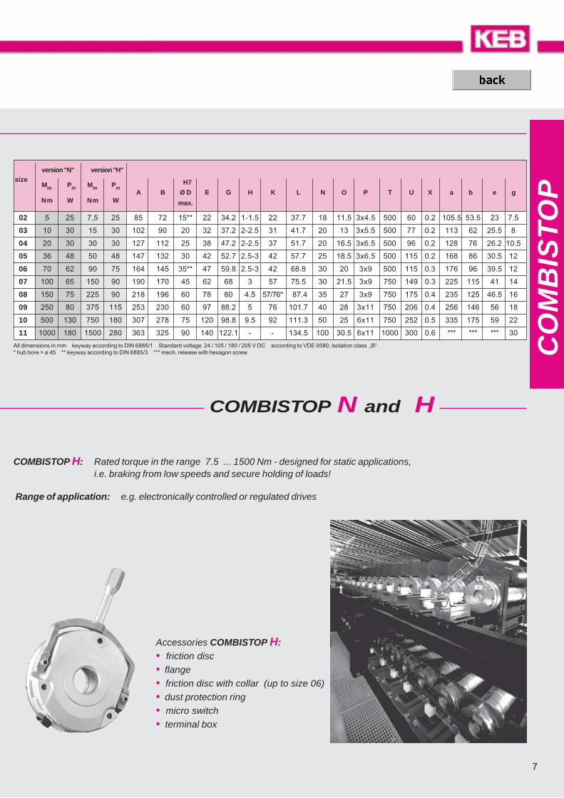
version "N" version "H"size
M2N P20 M2N P20 H7
A B Ø D E G H K L N O P T U X a b e gNm W Nm W max.
02 5 25 7,5 25 85 72 15** 22 34.2 1-1.5 22 37.7 18 11.5 3x4.5 500 60 0.2 105.5 53.5 23 7.5
03 10 30 15 30 102 90 20 32 37.2 2-2.5 31 41.7 20 13 3x5.5 500 77 0.2 113 62 25.5 8
04 20 30 30 30 127 112 25 38 47.2 2-2.5 37 51.7 20 16.5 3x6.5 500 96 0.2 128 76 26.2 10.5
05 36 48 50 48 147 132 30 42 52.7 2.5-3 42 57.7 25 18.5 3x6.5 500 115 0.2 168 86 30.5 12
06 70 62 90 75 164 145 35** 47 59.8 2.5-3 42 68.8 30 20 3x9 500 115 0.3 176 96 39.5 12
07 100 65 150 90 190 170 45 62 68 3 57 75.5 30 21.5 3x9 750 149 0.3 225 115 41 14
08 150 75 225 90 218 196 60 78 80 4.5 57/76* *87.4 35 27 3x9 750 175 0.4 235 125 46.5 16
09 250 80 375 115 253 230 60 97 88.2 5 76 101.7 40 28 3x11 750 206 0.4 256 146 56 18
10 500 130 750 180 307 278 75 120 98.8 9.5 92 111.3 50 25 6x11 750 252 0.5 335 175 59 22
11 1000 180 1500 280 363 325 90 140 122.1 - - 134.5 100 30.5 6x11 1000 300 0.6 *** *** *** 30
All dimensions in mm keyway according to DIN 6885/1 Standard voltage 24 / 105 / 180 / 205 V DC according to VDE 0580, isolation class „B“* hub bore > ø 45 ** keyway according to DIN 6885/3 *** mech. release with hexagon screw
COMBISTOP H: Rated torque in the range 7.5 ... 1500 Nm - designed for static applications,i.e. braking from low speeds and secure holding of loads!
Range of application: e.g. electronically controlled or regulated drives
Accessories COMBISTOP H:• friction disc• flange• friction disc with collar (up to size 06)• dust protection ring• micro switch• terminal box
COMBISTOP N and H

CO
MB
ISTO
P
5776*
5776*
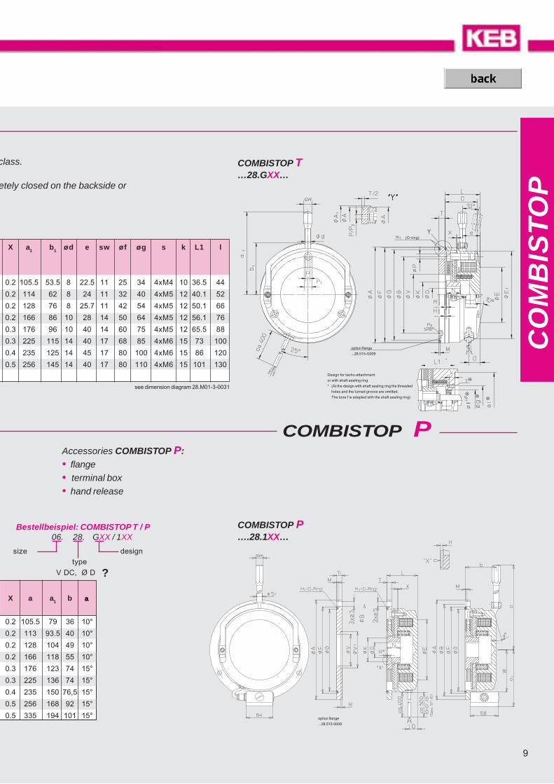
COMBISTOP T
Accessories COMBISTOP T :• flange • terminal box • hand release • shaft sealing ring
Two brakes designs which are always used whenever the application puts higher demands on the protection c
COMBISTOP T: the IP 65-brake with identical hole circle such as COMBISTOP N and H, optionally compleprepared for the attachment of tacho-generators (xx.28.GxT) or shaft sealing ring.
Range of application: e.g. general machine building, crane construction, ship gear, wind energy plants
COMBISTOP P : completely closed version in protection class IP66 with sealing of the mounting side andelectrical connection, optionally with internallyrunning connecting cable or attached terminalbox.
Range of application: e.g. general machine building, craneconstruction, ship gear, wind energy plants
H7
size M2N P20 øA øB øD øE øF øG H øK L M M1 N O R S S1 sw T T1 øV øV1 W
[Nm] [W] max.
02 4 20 108 100 15** 50 94 88 1-1.5 22 38 2.4 88x3 18 13.5 2 4.5 8 11 6 6 20 37 43
03 8 25 138 125 20 64 116.5 110 2-2.5 31 42.2 2.4 110x3 20 14 2 6.5 8 11 7 7 40 48 57.5
04 16 30 160 148 25 80 139 132 2-2.5 37 51.2 2.4 132x3 20 16 2 6.5 8 11 8.5 9 40 61 68
05 32 40 190 175 30 102 163 154 2.5-3 42 56.2 3.5 155x4 25 17 2 8.5 10 14 9 10 47 71 82
06 60 52 200 185 30 115 173 164 2.5-3 42 66.5 3.5 164x4 30 20 2 8.5 10 14 10 11 55 71 87
07 100 65 238 220 45 144 206 196 3 57 74 3.2 196x4 30 20 - 11 14 17 12 12 75 - 100
08 150 75 268 250 60 160 235 225 4.5 86.5 3.2 225x4 35 27 - 11 14 17 14 14 95 - 114
09 250 75 312 290 60 180 272 260 5 76 102 4 260x5 40 33 - 14 14 17 15 15 95 - 131.5
10 400 130 362 340 75 230 322 310 9.5 92 110 4 310x5 50 35 - 14 16 19 15 15 120 - 158
size M2N P20 øA1 øA øB C øD øE øE1 øF øG H øK L M M1 N O øP øP1 øP2 R T øV
[Nm] [W] h8 max.
H8
02 4 20 102 98 72 34 15** 50 85 94.5 88 1-1.5 22 37.5 2.4 88x3 18 11 4.5 8 M4 0.5 6 37
03 8 25 123 118 90 37 20 64 102 116 109.5 2-2.5 31 41.1 2.4 110x3 20 12.5 5.6 10 M5 1.5 7 48
04 16 30 148 143 112 47 25 80 127 138.5 132 2-2.5 37 51.1 2.4 132x3 20 16 6.5 11 M6 1.5 9 60
05 32 40 170 165 132 51.5 30 102 147 158.5 152 2.5-3 42 56.1 2.4 152x3 25 17 6.5 11 M6 2 9 70
06 60 52 186 180 145 60 35** 115 164 176.5 170 2.5-3 42 66.5 2.4 170x3 30 20 9 15 M8 2 11 70
07 100 65 216 210 170 68 45 144 193 200.5 196 2.0 57 74 3.5 196x4 30 20 9 15 M8 3.0 12 75
08 150 75 246 240 196 77 60 160 217 235.5 225 4.5 86.5 3.2 225x4 35 25 9 15 M8 3.5 14 95
09 250 75 280 240 230 86 60 180 254 272 260 5.0 76 102 3.5 260x5 40 33 11 18 M10 4.0 15 95
all dimensions in mm keyway according to DIN 6885/1 standard voltage 24 / 105 / 180 / 205 V DC according to VDE 0580, ISO-class „B“ * hub bore > ø 45** keyway according to DIN 6885/3
all dimensions in mm keyway according to DIN 6885/1 standard voltage 24 / 105 / 180 / 205 V DC according to VDE 0580, ISO-class „B“ * hub bore > ø 45** keyway according to DIN 6885/3
9
CO
MB
IST
OP
COMBISTOP P
COMBISTOP P….28.1XX…
COMBISTOP T…28.GXX…
V DC, Ø D ?
Accessories COMBISTOP P:• flange• terminal box• hand release
n class.
pletely closed on the backside or
X a a1 b aaaaa
0.2 105.5 79 36 10°
0.2 113 93.5 40 10°
0.2 128 104 49 10°
0.2 166 118 55 10°
0.3 176 123 74 15°
0.3 225 136 74 15°
0.4 235 150 76,5 15°
0.5 256 168 92 15°
0.5 335 194 101 15°
X a1 b1 ød e sw øf øg s k L1 l
0.2 105.5 53.5 8 22.5 11 25 34 4xM4 10 36.5 44
0.2 114 62 8 24 11 32 40 4xM5 12 40.1 52
0.2 128 76 8 25.7 11 42 54 4xM5 12 50.1 66
0.2 166 86 10 28 14 50 64 4xM5 12 56.1 76
0.3 176 96 10 40 14 60 75 4xM5 12 65.5 88
0.3 225 115 14 40 17 68 85 4xM6 15 73 100
0.4 235 125 14 45 17 80 100 4xM6 15 86 120
0.5 256 145 14 40 17 80 110 4xM6 15 101 130
(O-ring)
option flange
...28.515-G009
Design for tacho-attachment
or with shaft sealing ring
* (At the design with shaft sealing ring the threaded
holes and the turned groove are omitted.
The bore f is adapted with the shaft sealing ring)
option flange
...28.515-0009
Bestellbeispiel: COMBISTOP T / P06. 28. GXX / 1XX
typedesignsize
see dimension diagram 28.M01-3-0031
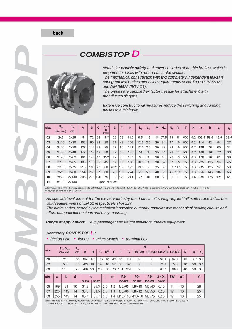
COMBISTOP D
CO
MB
ISTO
P
1 & 2size M2N P20 A B CD
E F H L1 L2 M N1 N2 R1 T X a b e1 e2(Nm stat) (W)
(max)
02 2x5 2x25 85 72 22 15** 22 36 91.2 9.5 1.5 18 27.5 13 8 500 0.2 105.5 53.5 45.5 22.5
03 2x10 2x30 102 90 32 20 31 48 106 12.5 2.5 20 34 17 10 500 0.2 114 62 54 27
04 2x20 2x30 127 112 38 25 37 60 121 12.5 2.5 20 39 23 10 500 0.2 128 76 65 31
05 2x36 2x48 147 132 42 30 42 70 135 14 3 25 41 21 11 500 0.2 168 86 72 33
06 2x70 2x62 164 145 47 35** 42 70 157 16 3 30 45 20 13 500 0.3 176 96 81 36
07 2x100 2x65 190 170 62 45 57 75 180 18.5 3 30 59 37 15 750 0.3 225 115 94 45
08 2x150 2x75 218 196 78 60 57/76* 100 193 19.5 5 35 55 33 14.5 750 0.3 235 125 97 50
09 2x250 2x80 254 230 97 60 76 100 224 22 5.5 40 65 45 16.5 750 0.3 256 146 107 56
10 2x500 2x130 306 278 120 75 92 120 241 27 10 50 63 36 17 750 0.4 335 175 121 61
11 2x1000 2x180 upon request
size2 x M2N P20
H L
(Nm stat.) (W) A B C DH7 E F G D8.230 D8.630 D8.230 D8.630 N O Xn
05 25 60 154 146 132 30 42 65 147 3 3 53.8 54.3 25 19.5 0.3
07 50 65 203 188 170 40 57 65 190 3 3 74.3 74.3 30 20 0.4
09 125 75 268 230 230 60 76 101 254 5 5 98.7 98.7 40 20 0.5
As special development for the elevator industry the dual-circuit spring-applied faill-safe brake fulfills thevalid requirements of EN 81 respectively TRA 227.The brake series, tested by the technical inspection authority, contains two mechanical braking circuits andoffers compact dimensions and easy mounting.
Range of application: e.g. passenger and freight elevators, theatre equipment
stands for double safety and covers a series of double brakes, which isprepared for tasks with redundant brake circuits.The mechanical construction with two completely independent fail-safespring-applied brakes meets the requirements according to DIN 56921and DIN 56925 (BGV C1).The brakes are supplied ex factory, ready for attachment withpreadjusted air gaps.
Extensive constructional measures reduce the switching and runningnoises to a minimum.
size a b d e l m P1* P2* P3* 2 x XV SW aaaaa ° ddddd°D8.230 D8.630 ISO 4762 ISO 4762 ISO 4762 D8.630
05 169 89 10 34.8 35.3 2.5 1.2 M6x65 M6x10 M5x40 0.15 14 10 28
07 225 115 14 33.5 33.5 2.5 1.3 M8x80 M8x12 M6x50 0.20 17 10 25
09 255 145 14 65.7 65.7 3.0 1.4 M10x100 M10x16 M8x75 0.25 17 10 25all dimensions in mm keyway according to DIN 6885/1 standard voltage 24 / 105 / 180 / 205 V DC according to VDE 0580, ISO-class „B“* hub bore > ø 45 ** keyway according to DIN 6885/3 see dimension diagram D8.M01-4-0707
all dimensions in mm keyway according to DIN 6885/1 standard voltage 24 / 105 / 180 / 205 V DC according to VDE 0580, ISO-class „B“ * hub bore > ø 45** keyway according to DIN 6885/3
Accessory COMBISTOP L :• friction disc • flange • micro switch • terminal box

11
CO
MB
IST
OP
COMBISTOP L
!�
!
!�
���
COMBISTOP D…38.DDN…
V DC, Ø D1, Ø D2 ?
V DC, Ø D ?
d1 d2 m Z Z1 Z2 Z3
1/2/3
.5 34.6 39 0.8 M4 3x8.8 3x8.8 3x8.8
37.7 47.5 1 M5 3x8.8 3x8.8 3x8.8
47.8 54.4 1.4 M6 3x8.8 3x8.8 3x8.8
53.4 55.9 1.5 M6 3x10.9 3x8.8 3x8.8
60.3 64.5 1.8 M8 3x10.9 3x8.8 3x8.8
68.8 77.6 2 M8 6x8.8 3x8.8 3x8.8
80.8 82.7 2 M8 6x10.9 3x10.9 3x10.9
89.4 95.4 2.3 M10 6x8.8 3x10.9 3x10.9
99.5 105 2.7 M10 6x10.9 6x8.8 3x8.8
Accessories COMBISTOP D :• friction disc • dust protection ring• micro switch • flange• terminal box • friction disc with collar (up to size 06)
hub variation 1
hub variation 2
COMBISTOP L …D8.230… with hand release
COMBISTOP L …D8.630… with hand releasewith backlash-free hub-lining-system
Range of application:e.g. theatre equipment, passenger andfreight elevators
see dimension diagram 38.003-3-0714
4 x attachment for friction disc
4 x brake attachment
backlash-free
hub-lining-system
Fastening Screws
ordering example: COMBISTOP D06. 38. DDN
size designtype
ordering example: COMBISTOP L05. D8. 230/630
size design
type
CO
MB
ISTO
P���%
��
The use of COMBISTOP can be fitted with a micro switch for moni-toring the functions and the wear. The use of COMBISTOP with mi-cro switch is particularly sensible for braking motors on hoistinggears that are operated with frequency inverters.
Detailed mounting dimensions and technical data are provided in thedimension sheet 08.M01-3-0604.
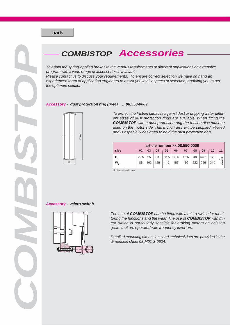
To protect the friction surfaces against dust or dripping water differ-ent sizes of dust protection rings are available. When fitting theCOMBISTOP with a dust protection ring the friction disc must beused on the motor side. This friction disc will be supplied nitratedand is especially designed to hold the dust protection ring.
To adapt the spring-applied brakes to the various requirements of different applications an extensiveprogram with a wide range of accessories is available.Please contact us to discuss your requirements. To ensure correct selection we have on hand anexperienced team of application engineers to assist you in all aspects of selection, enabling you to getthe optimum solution.
all dimensions in mm
Accessory - dust protection ring (IP44) …08.550-0009
Accessory - micro switch
article number xx.08.550-0009size 02 03 04 05 06 07 08 09 10 11
B1 22.5 25 33 33.5 38.5 45.5 49 54.5 63
W5 86 103 129 149 167 195 222 259 310 upon
requ
est
COMBISTOP Accessories

13
���
����
����
���
��
���
����
����
���
����
����
���
���%�
��
����
&���&��
CO
MB
IST
OP
Friction discs and flanges provide suitable counter-rotation surfaces for the spring applied brakes and are available in hard-ened and rustproof design.
Accessory - friction discs …08.451…
Accessory - friction discs with collar …08.515… article number xx.08.515-xxxx
size 02 03 04 05 06 07 08 09 10 11
B 72 90 112 132 145
P 4.5 5.5 6.5 6.5 9
T1 1.5 2 2 2 2.5
V1 27 35.5 42.5 47 51
W1 88.5 106 132 153 171
weight[kg] 0.05 0.10 0.15 0.25 0.35
article number xx.38.510-0009
size 00 02 03 04 05 06 07 08 09 10 11
B 52 72 90 112 132 145 170 196 230 278 325
P4 3x4,3 3x5,3 3x6,4 3x6,4 3x9 3x9 3x9 3x11 6x11 8x11
S1 3xM4 3xM5 3xM6 3xM6 3xM8 3xM8 3xM8 3xM10 6xM10 8xM10
T4 5 6 7 9 9 11 11 11 11 12.5 20
V4 26 20 30 40 45 55 65 75 90 120 160
W3 60 83 100 125 145 163 190 217 254 306 363
weight 0.08 0.20 0.35 0.75 1 1.50 2.10 2.70 3.70 5.90 12.7[kg]
article number xx.08.451-xxxx
size 02 03 04 05 06 07 08 09 10 11
B 72 90 112 132 145 170 196 230 278
P 4.5 5.5 6.5 6.5 9 9 9 11 11
T1 1.5 2 2 2 2.5 2.5 2.5 3 4
P3 7.5 8.5 10.5 18 18 18 14.5 17 17
V2 27 35.5 42.5 47 51 85 100 105 198
W2 82 98 123 146 157 188 214 250 302
weight [kg] 0.05 0.10 0.15 0.22 0.30 0.40 0.64 0.93 1.50
all dimensions in mm
all dimensions in mm
all dimensions in mm
Accessory - flange with collar for dust protection ring …08.510…

��
����
���
���
���
��
��
��� ��� ��� ��
����
���
���
��
��
��
����
���
��
���
��
��
��� ��� ��� ��
����
���
�����
��
��
��
CO
MB
ISTO
P
switching frequency per hour switching frequency per hour
WRmax [J]WRmax [J]
Friction switching frequency Type M, P, T Friction switching frequency Type N, H, D
max. speed
max. speed J gmin Xn
operating type M, P, T type N, H, D type M, P, T type N, H, D
size stop emergency stop emergency stop[rpm] [rpm] [rpm] [10-3 kgm2] [10-3 kgm2] [mm] [mm]
0B 3000 6000 - 0.001 - - -02 3000 6000 6000 0.025 0.025 5.5 0.403 3000 6000 6000 0.072 0.072 6.5 0.504 3000 6000 6000 0.136 0.136 8 0.605 3000 5000 5000 0.35 0.35 10 0.606 3000 5000 5000 0.56 0.56 10 107 3000 4500 4500 1.57 1.57 10 108 3000 3500 3500 5.92 5.92 11 1.209 1500 3000 3000 7.38 7.38 12 1.210 1500 3000 3000 20.54 20.54 14 1.511 1500 2000 180.7 28 1.5
Technical data
Permissible friction WRmax [J] dependention the switching frequency
Valid only for the stated revolutions per minute
type M, P, T, N, H, D size 0B. … 07. - 3000 rpmtype P, T, N, H, D size 08. … 11. - 1500 rpm
The values for WRmax are valid for standard brakes and a second friction surface of casting. Depending onapplication these values may be exceeded or remained under. Rustfree friction discs, or speeds higher thanspecified in the diagram, reduce the permissible friction work considerably. If the rated torque of the brake isreduced by turning the adjustment ring (optional) the permissible friction work increases.
Red line for brake without friction disc
gmin min. permissible lining thickness [mm]
15
CO
MB
IST
OP
COMBISTOP
variations COMBISTOP type N, H, D
Switching cycles COMBISTOP with POWERBOX
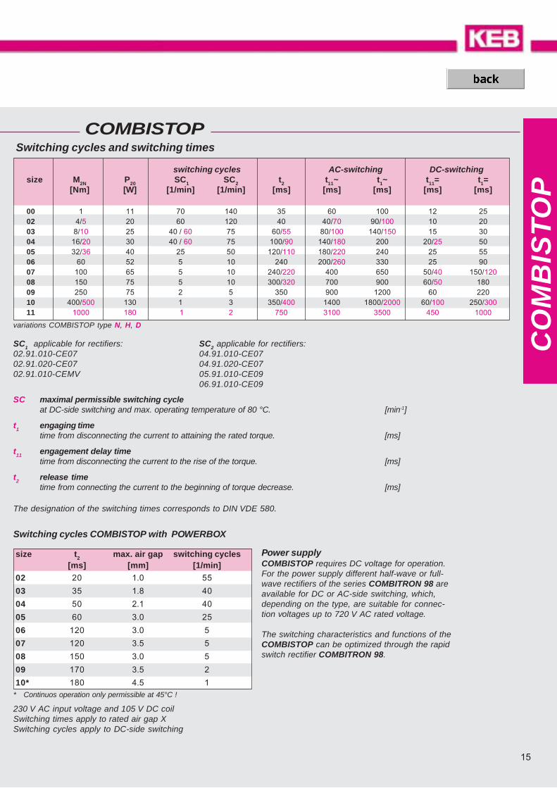
230 V AC input voltage and 105 V DC coilSwitching times apply to rated air gap XSwitching cycles apply to DC-side switching
SC maximal permissible switching cycleat DC-side switching and max. operating temperature of 80 °C. [min-1]
t1 engaging timetime from disconnecting the current to attaining the rated torque. [ms]
t11 engagement delay timetime from disconnecting the current to the rise of the torque. [ms]
t2 release timetime from connecting the current to the beginning of torque decrease. [ms]
The designation of the switching times corresponds to DIN VDE 580.
Switching cycles and switching times
switching cycles AC-switching DC-switchingsize M2N P20 SC1 SC2 t2 t11~ t1~ t11= t1=
[Nm] [W] [1/min] [1/min] [ms] [ms] [ms] [ms] [ms]
00 1 11 70 140 35 60 100 12 2502 4/5 20 60 120 40 40/70 90/100 10 2003 8/10 25 40 / 60 75 60/55 80/100 140/150 15 3004 16/20 30 40 / 60 75 100/90 140/180 200 20/25 5005 32/36 40 25 50 120/110 180/220 240 25 5506 60 52 5 10 240 200/260 330 25 9007 100 65 5 10 240/220 400 650 50/40 150/12008 150 75 5 10 300/320 700 900 60/50 18009 250 75 2 5 350 900 1200 60 22010 400/500 130 1 3 350/400 1400 1800/2000 60/100 250/30011 1000 180 1 2 750 3100 3500 450 1000
SC1 applicable for rectifiers: SC2 applicable for rectifiers:02.91.010-CE07 04.91.010-CE0702.91.020-CE07 04.91.020-CE0702.91.010-CEMV 05.91.010-CE09
06.91.010-CE09
size t2 max. air gap switching cycles[ms] [mm] [1/min]
02 20 1.0 55
03 35 1.8 40
04 50 2.1 40
05 60 3.0 25
06 120 3.0 5
07 120 3.5 5
08 150 3.0 5
09 170 3.5 2
10* 180 4.5 1* Continuos operation only permissible at 45°C !
Power supplyCOMBISTOP requires DC voltage for operation.For the power supply different half-wave or full-wave rectifiers of the series COMBITRON 98 areavailable for DC or AC-side switching, which,depending on the type, are suitable for connec-tion voltages up to 720 V AC rated voltage.
The switching characteristics and functions of theCOMBISTOP can be optimized through the rapidswitch rectifier COMBITRON 98.
� () ����
CO
MB
IPE
RM
COMBIPERM P1
COMBIPERM 22
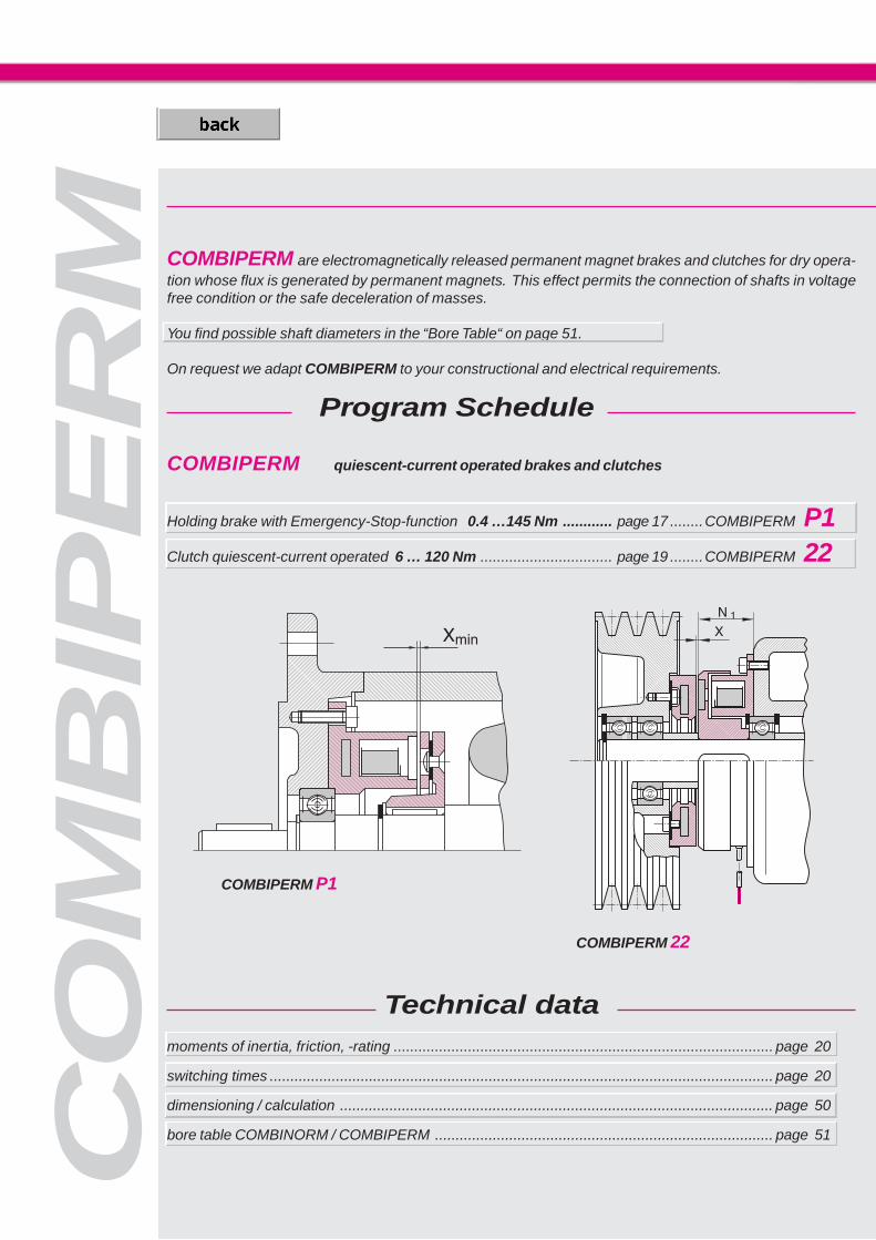
COMBIPERM quiescent-current operated brakes and clutches
Holding brake with Emergency-Stop-function 0.4 …145 Nm ............ page 17 ........COMBIPERM P1Clutch quiescent-current operated 6 … 120 Nm ................................ page 19 ........COMBIPERM 22
Technical datamoments of inertia, friction, -rating ............................................................................................ page 20
switching times .......................................................................................................................... page 20
dimensioning / calculation ......................................................................................................... page 50
bore table COMBINORM / COMBIPERM .................................................................................. page 51
COMBIPERM are electromagnetically released permanent magnet brakes and clutches for dry opera-tion whose flux is generated by permanent magnets. This effect permits the connection of shafts in voltagefree condition or the safe deceleration of masses.
You find possible shaft diameters in the “Bore Table“ on page 51.
On request we adapt COMBIPERM to your constructional and electrical requirements.
Program Schedule
17
CO
MB
IPE
RM
��
��
��
��
%�
� () � �
����*
�����*
+�,
��
�
V DC, Ø d, Ø d1 ?
V DC, Ø d30 ?
type
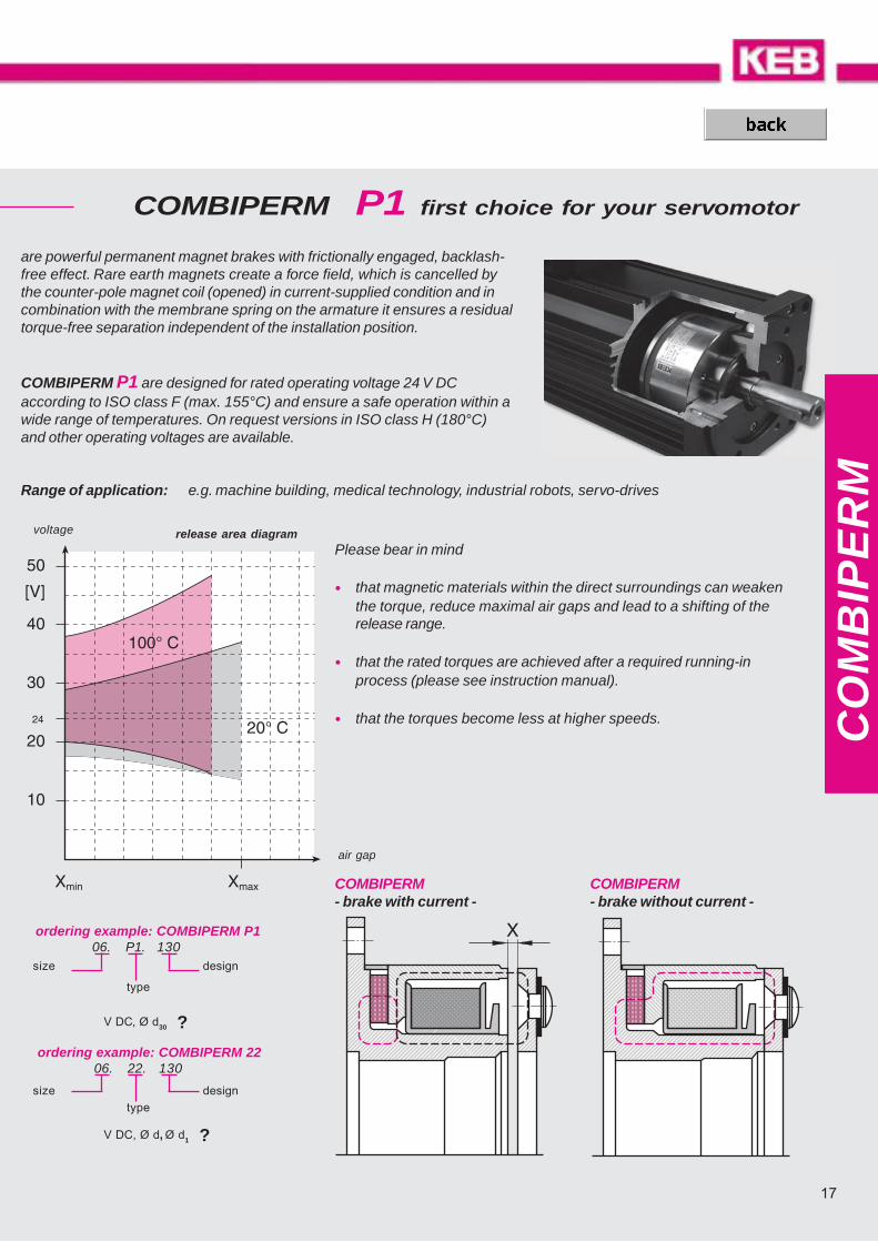
are powerful permanent magnet brakes with frictionally engaged, backlash-free effect. Rare earth magnets create a force field, which is cancelled bythe counter-pole magnet coil (opened) in current-supplied condition and incombination with the membrane spring on the armature it ensures a residualtorque-free separation independent of the installation position.
COMBIPERM P1 are designed for rated operating voltage 24 V DCaccording to ISO class F (max. 155°C) and ensure a safe operation within awide range of temperatures. On request versions in ISO class H (180°C)and other operating voltages are available.
voltage
air gap
COMBIPERM P1 first choice for your servomotor
COMBIPERM- brake with current -
Please bear in mind
• that magnetic materials within the direct surroundings can weakenthe torque, reduce maximal air gaps and lead to a shifting of therelease range.
• that the rated torques are achieved after a required running-inprocess (please see instruction manual).
• that the torques become less at higher speeds.
release area diagram
ordering example: COMBIPERM 2206. 22. 130
designsize
Range of application: e.g. machine building, medical technology, industrial robots, servo-drives
COMBIPERM- brake without current -
ordering example: COMBIPERM P106. P1. 130
type
designsize
COMBIPERM P1--
��*� �
���
���
.
���
��/
$��
$��
�
����� ���
.��
��*� �
.��
0
���� �
��"
�� ()
���� �
���
��
1
��������� ��������� ���������
��������� ��������� ���������
�
��2� ��
.�����������
��2� ��
���������
�
�
&
���
�
��*
��*
���
$
���
���������
�
.
CO
MB
IPE
RM
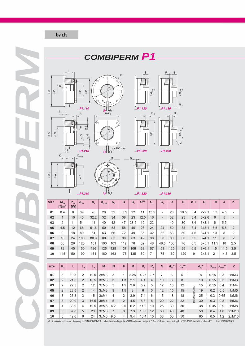
01 0.4 8 39 28 28 32 33.5 22 11 13.5 - 28 19.5 3.4 2x2.1 5.3 4.5 -
02 1 10 45 32.2 32 34 38 23 12.5 16 - 32 23 3.4 3x2.6 6 5 -
03 2 11 54 41 40 42 47 28.5 19 22 - 40 30 3.4 3x3.1 6 5.5 -
05 4.5 12 65 51.5 50 53 58 40 26 24 24 50 38 3.4 3x3.1 6.5 5.5 2
06 9 18 80 64 63 66 72 49 35 32 32 63 50 4.5 3x4.1 10 8 2
07 18 24 100 80.8 80 83 90 63 42 38 38 80 60 5.5 3x4.1 11 8 2
08 36 26 125 101 100 103 112 78 52 48 48.5 100 76 6.5 3x5.1 11.5 10 2.5
09 72 40 150 126 125 128 137 106 62 57 58 125 95 6.5 3x6.1 15 11.5 3.5
10 145 50 190 161 160 163 175 135 80 71 75 160 120 9 3x8.1 21 14.5 3.5
01 3 19.5 2 10.5 2xM3 3 1 2.25 4.25 2.7 7 6 6 8 0.15 0.3 1xM3
02 2 21.5 2 10.5 3xM3 3 1.3 2.1 4.1 4 10 8 8 10 0.15 0.3 1xM3
03 2 22.5 2 12 3xM3 3 1.5 2.6 5.2 5 12 10 12 15 0.15 0.4 1xM4
05 2 28.5 2 14 3xM3 3 1.5 3 6 5 12 15 15 19 0.2 0.5 1xM5
06 3 26.8 3 15 3xM4 4 2 3.9 7.4 6 15 18 18 25 0.3 0.65 1xM6
07 3 29.9 3 16.5 3xM4 5 2 4.5 8.5 8 20 22 22 30 0.3 0.8 1xM6
08 4 33.9 4 19.5 3xM5 6.2 2.5 6.2 11.2 10 25 30 30 38 0.35 0.9 1xM8
09 5 37.8 5 23 3xM6 7 3 7.3 13.3 12 30 40 40 50 0.4 1.0 2xM10
10 6 42.6 6 24 3xM8 9.5 4 9.4 16.4 15 38 50 50 65 0.5 1.2 2xM10
size K1 L L1 L2 M N P R R1 R2 S d20H7 d30
H7 d30H7 Xmin Xmax
20° Z
all dimensions in mm keyway to DIN 6885/1-P9 standard voltage 24 V DC (release range + 6 % / - 10 %) according to VDE 0580, isolation class F“ hub DIN 6885/1
size M2N P 20 A h8 A1 A2 h8 A3 B B1 CH8 C1 C2 D E Ø F G H J K
[Nm] [W]
upon
req
uest
*
19
CO
MB
IPE
RM
COMBIPERM 22
...22.710 ...22.730 ...22.740
...22.210 ...22.230 ...22.240
...22.110 ...22.130 ...22.140...22.110...22.110 ...22.130...22.130 ...22.140...22.140
...22.710...22.710 ...22.730...22.730 ...22.740...22.740
...22.210...22.210 ...22.230...22.230 ...22.240...22.240
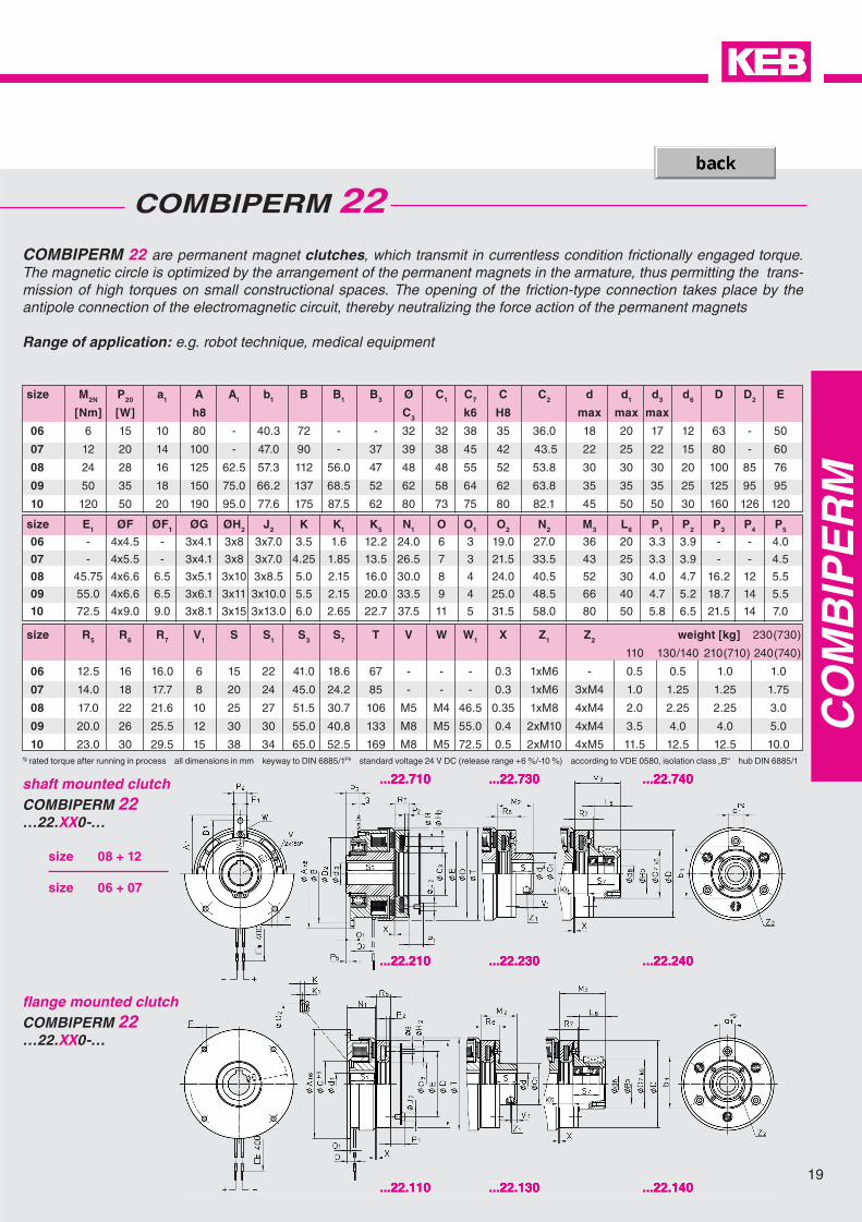
COMBIPERM 22 are permanent magnet clutches, which transmit in currentless condition frictionally engaged torque. The magnetic circle is optimized by the arrangement of the permanent magnets in the armature, thus permitting the trans-mission of high torques on small constructional spaces. The opening of the friction-type connection takes place by the antipole connection of the electromagnetic circuit, thereby neutralizing the force action of the permanent magnets
Range of application: e.g. robot technique, medical equipment
1) rated torque after running in process all dimensions in mm keyway to DIN 6885/1P9 standard voltage 24 V DC (release range +6 %/-10 %) according to VDE 0580, isolation class „B“ hub DIN 6885/1
fl ange mounted clutchCOMBIPERM 22 …22.XX0-…
shaft mounted clutchCOMBIPERM 22 …22.XX0-…
size M2N P20 a1 A A1 b1 B B1 B3 Ø C1 C7 C C2 d d1 d3 d6 D D2 E
[Nm] [W] h8 C3 k6 H8 max max max
06 6 15 10 80 - 40.3 72 - - 32 32 38 35 36.0 18 20 17 12 63 - 50
07 12 20 14 100 - 47.0 90 - 37 39 38 45 42 43.5 22 25 22 15 80 - 60
08 24 28 16 125 62.5 57.3 112 56.0 47 48 48 55 52 53.8 30 30 30 20 100 85 76
09 50 35 18 150 75.0 66.2 137 68.5 52 62 58 64 62 63.8 35 35 35 25 125 95 95
10 120 50 20 190 95.0 77.6 175 87.5 62 80 73 75 80 82.1 45 50 50 30 160 126 120
size E1 ØF ØF1 ØG ØH2 J2 K K1 K5 N1 O O1 O2 N2 M3 L6 P1 P2 P3 P4 P5
06 - 4x4.5 - 3x4.1 3x8 3x7.0 3.5 1.6 12.2 24.0 6 3 19.0 27.0 36 20 3.3 3.9 - - 4.0
07 - 4x5.5 - 3x4.1 3x8 3x7.0 4.25 1.85 13.5 26.5 7 3 21.5 33.5 43 25 3.3 3.9 - - 4.5
08 45.75 4x6.6 6.5 3x5.1 3x10 3x8.5 5.0 2.15 16.0 30.0 8 4 24.0 40.5 52 30 4.0 4.7 16.2 12 5.5
09 55.0 4x6.6 6.5 3x6.1 3x11 3x10.0 5.5 2.15 20.0 33.5 9 4 25.0 48.5 66 40 4.7 5.2 18.7 14 5.5
10 72.5 4x9.0 9.0 3x8.1 3x15 3x13.0 6.0 2.65 22.7 37.5 11 5 31.5 58.0 80 50 5.8 6.5 21.5 14 7.0
size R5 R6 R7 V1 S S1 S3 S7 T V W W1 X Z1 Z2 weight [kg] 230(730)
110 130/140 210(710) 240(740)
06 12.5 16 16.0 6 15 22 41.0 18.6 67 - - - 0.3 1xM6 - 0.5 0.5 1.0 1.0
07 14.0 18 17.7 8 20 24 45.0 24.2 85 - - - 0.3 1xM6 3xM4 1.0 1.25 1.25 1.75
08 17.0 22 21.6 10 25 27 51.5 30.7 106 M5 M4 46.5 0.35 1xM8 4xM4 2.0 2.25 2.25 3.0
09 20.0 26 25.5 12 30 30 55.0 40.8 133 M8 M5 55.0 0.4 2xM10 4xM4 3.5 4.0 4.0 5.0
10 23.0 30 29.5 15 38 34 65.0 52.5 169 M8 M5 72.5 0.5 2xM10 4xM5 11.5 12.5 12.5 10.0
size 08 + 12
size 06 + 07
CO
MB
IPE
RM COMBIPERM P1 / 22
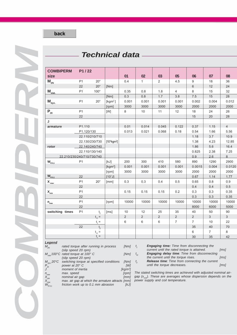
size 01 02 03 05 06 07 08M2N P1 20° 0.4 1 2 4.5 9 18 36
22 20° [Nm] 6 12 24
Mstat. P1 100° 0.35 0.8 1.8 4 8 15 32
[Nm] 0.3 0.8 1.7 3.8 7.5 15 28
Mdyn. P1 20° [kgm2 ] 0.001 0.001 0.001 0.001 0.002 0.004 0.012
[rpm] 3000 3000 3000 3000 2000 2000 2000
P20 P1 [W] 8 10 11 12 18 24 26
22 15 20 28
J
armature P1.110 0.01 0.014 0.045 0.122 0.37 1.15 4
P1.120/130 0.013 0.021 0.068 0.18 0.54 1.66 5.56
22.110/210/710 1.18 3.7 10.9
22.130/230/730 [10-4kgm2] 1.38 4.23 12.85
rotor 22.140/240/740 1.86 5.6 16.4
22.110/130/140 0.825 2.38 7.25
22.210/230/240/710/730/740 0.9 2.6 8
WR 0,1 P1 [kJ] 200 300 410 580 890 1290 2900
[kgm2] 0.001 0.001 0.001 0.001 0.0015 0.004 0.0120
[rpm] 3000 3000 3000 3000 2000 2000 2000WR 0,1 22 [107J] 0.67 1.14 1.77
X max P1 20° [mm] 0.3 0.3 0.4 0.5 0.65 0.8 0.9
22 0.4 0.4 0.5
Xmin P1 0.15 0.15 0.15 0.2 0.3 0.3 0.35
22 0.3 0.3 0.35
nmax P1 [rpm] 10000 10000 10000 10000 10000 10000 10000
22 8000 6000 5000
switching times P1 t2
[ms] 10 12 25 35 40 50 90
t11
= 2 2 2 2 2 3 3
t1 = 6 6 6 7 7 10 22
22 t2
35 40 70
t11
= 6 7 8t1 = 30 35 42
LegendM2N rated torque after running in process [Nm]
(slip speed 20 rpm)Mstat.100°C rated torque at 100° C [Nm]
(slip speed 20 rpm)Mdyn..20°C switching torque at specified conditions [Nm]P20 power at 20° C [W]J moment of inertia [kgm²]nmax max. speed [rpm]Xmin nominal air gap [mm]Xmax max. air gap at which the armature attracts [mm]WR 0,1 friction work up to 0.1 mm abrasion [kJ]
Technical data
t1 Engaging time: Time from disconnecting thecurrent until the rated torque is attained. [ms]
t11 Engaging delay time: Time from disconnectingthe current until the torque rises. [ms]
t2 Release time: Time from connecting the currentuntil the torque decreases. [ms]
The stated switching times are achieved with adjusted nominal air-gap (xmin). These are averages whose dispersion depends on thepower supply and coil temperature.
21
CO
MB
IPE
RM
��%
%����
���
%����
���
%����
���
%�
��
� % �� %� %���� ��� %�������
�# �! �& �% ���� �' ��
���
��
COMBIPERM
WRmax [J]
switching frequency per hour [h-1]
09 1072 145
50 120
62 130
55 110
0.036 0.1
2000 2000
40 50
35 50
11.5 39
16 53
31.7 95
36.6 110
46.6 140
21.9 67.4
24 73
6200 13000
0 0.036 0.1
2000 2000
2.86 4.66
1 1.2
0.6 0.7
0.4 0.5
0.4 0.5
8000 8000
4000 3000
140 190
7 12
25 65
90 105
10 12
50 60
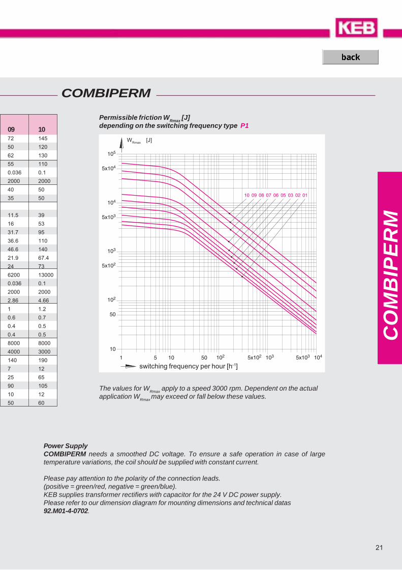
The values for WRmax
apply to a speed 3000 rpm. Dependent on the actualapplication W
Rmax may exceed or fall below these values.
Permissible friction WRmax [J]depending on the switching frequency type P1
Power SupplyCOMBIPERM needs a smoothed DC voltage. To ensure a safe operation in case of largetemperature variations, the coil should be supplied with constant current.
Please pay attention to the polarity of the connection leads.(positive = green/red, negative = green/blue).KEB supplies transformer rectifiers with capacitor for the 24 V DC power supply.Please refer to our dimension diagram for mounting dimensions and technical datas92.M01-4-0702.

CO
MB
INO
RM
V DC, Ø d1, Ø d ?
type
Program Schedule
Technical data
Moments of inertia, friction, rating ...................................................... page 34
Switching times .................................................................. page 34
Dimensioning / calculations ............................................................... page 50
bores table COMBINORM / COMBIPERM ....................................... page 51
COMBINORM - operating-current operated brakes and clutches use the flux of an electromagnet, con-centrated on two pole surfaces, for the connecting, separating or holding of shafts and the connected loads.
COMBINORM covers a complete program with brakes, clutches and combinations as installation and at-tachment components for the applications in machines, plants and equipment in the application range of 0.5to 500 Nm.
On request we adapt the COMBINORM to your constructional and electrical requirements.
ordering example: COMBINORM C06. 03. 130
designsize
COMBINORM Operating-current operated brakes and clutches
Operating current brake 0.5 … 500 Nm .............................................. page 24 ....... COMBINORM BOperating current clutch-brake-combination 7 … 500 Nm ................ page 26 ....... COMBINORM KOperating current clutch 0.5 … 500 Nm ............................................. page 26 ....... COMBINORM COperating current toothed clutch 21 … 390 Nm................................ page 32 ....... COMBINORM T
23
CO
MB
INO
RM
�� � ���&
�
� � ����� � & %
���� &
COMBINORM
�� �
&
%
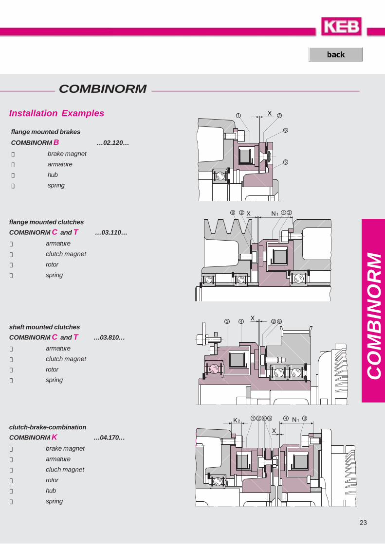
Installation Examples
flange mounted clutches
COMBINORM C and T …03.110…
➁ armature
➂ clutch magnet
➃ rotor
➅ spring
clutch-brake-combination
COMBINORM K …04.170…
➀ brake magnet
➁ armature
➂ cluch magnet
➃ rotor
➄ hub
➅ spring
shaft mounted clutches
COMBINORM C and T …03.810…
➁ armature
➂ clutch magnet
➃ rotor
➅ spring
flange mounted brakes
COMBINORM B …02.120…
➀ brake magnet
➁ armature
➄ hub
➅ spring

CO
MB
INO
RM
��� 5#
��
6���
��
��
.%
��
�
��
��
�2�
0��������
-��2%
��
���&
��'��
...02.320
COMBINORM B
d4 ¹ d5
are the most economical solution for the deceleration and holding of loads for the flange- and shaft-mounted installation in machines and plants.
The magnets with a rated voltage of 24 V DC are designed according to ISO class B and are available invarious special voltages on request.
size M2N P 20 Ah8 B CH8 C1 C2 d/d4 d5 D E F G H J K K1
[Nm] [W] max
01 0.5 6 39 33.5 11 13.5 - 6 28 19.5 3,4 2 x 2.1 5.3 4.5 - -
02 0.75 6 45 38 13 16 13.6 8 32 23 3,4 3 x 2.6 6 5 3 1.1
03 1.5 8 54 47 19 22 20 10 40 30 3,4 3 x 3.1 6 5.5 3 1.1
05 3 10 65 58 26 24 27 15 50 38 3,4 3 x 3.1 6.5 5.5 3.2 1.3
06 7 12 80 72 35 32 36 20 18 63 50 4,5 3 x 4.1 10 8 3.5 1.6
07 15 16 100 90 42 38 43.5 22 21 80 60 5,5 3 x 4.1 11 8 4.25 1.85
08 30 21 125 112 52 48 53.8 30 28 100 76 6,6 3 x 5.1 11.5 10 5 2.15
09 65 28 150 137 62 58 63.8 35 35 125 95 6,6 3 x 6.1 15 11.5 5.5 2.15
10 130 38 190 175 80 73 82.1 45 44 160 120 9 3 x 8.1 21 14.5 6 2.65
11 250 50 230 215 100 92 102.1 60 200 158 9 3 x 10.1 25 17.5 7 3.15
12 500 65 290 270 125 112 127.4 70 250 210 11 4 x 12.1 28 20.5 8 4.15
13 Dimensions and technical data see drawing 02.004-4-01001
All dimensions in mm keyway according to DIN 6885/1-P9 Standard voltage 24 V DC VDE 0580, ISO-class „B“
Shaft mounted brakesCOMBINORM B…02.320…
available shaft diameters page 51

25
��� 5#
��
6���
��
�*�#
�*�
��
�
�
.
�� ��
�"
��
�/
�
�
�
��
.�
�2
-
.�
�2
-�*�
1
��
0�
��'��
CO
MB
INO
RM
...02.110 ...02.120 ...02.130
M N N4 O O1 O3 P P6 R R1 R5 S S4 U V1 W4 X Z1 weight [kg]
110 120/130 320
9.3 13.7 5 1.5 1 2.3 4.3 7 2.5 0.1 1 x M 3 0.05 0.05
12.1 17 7.5 2 1.3 2.1 4.1 10 4 0.15 1 x M 3 0.1 0.1
14.7 20 7 2 1.5 2.7 5.3 12 5 0.15 1 x M 4 0.15 0.15
15 22 7.5 2 1.5 3 6 12 5 0.2 1 x M 5 0.2 0.25
18.8 18 31.2 6 3 19 2 9.3 3.8 7.3 6.3 15 45 39 6 M4 0.2 1 x M 6 0.3 0.3 0.8
24.3 20 34.2 7 3 21.5 2 13.2 4.3 8.3 6.9 20 52.5 45 8 M5 0.2 1 x M 6 0.5 0.6 1.5
31 22 38 8 4 24 2.5 13.5 6 11 9.3 25 58.5 56 10 M6 0.2 1 x M 8 0.9 1.1 2.7
36.9 24 40 9 4 25 3 13.8 6.9 12.9 10.9 30 62 61 12 M8 0.3 2 x M10 1.7 2 4.2
46.9 26 46.3 11 5 31.5 4 17.3 8.9 15.9 14.1 38 74 84 15 M10 0.3 2 x M10 3.2 4 7.8
59.2 30 12 5 4.5 11.2 20.2 48 19 0.4 2 x M12 5.9 7
68 35 15 6 5 13 24 55 22 0.4 2 x M12 11.2 13.5
Range of application:e.g. mail processing, winding equipment, door and gate systems, rollerconveyor, strapping machines, balancing machines, sorting machines.
Flange mounted brakesCOMBINORM B…02.1X0…
CO
MB
INO
RM
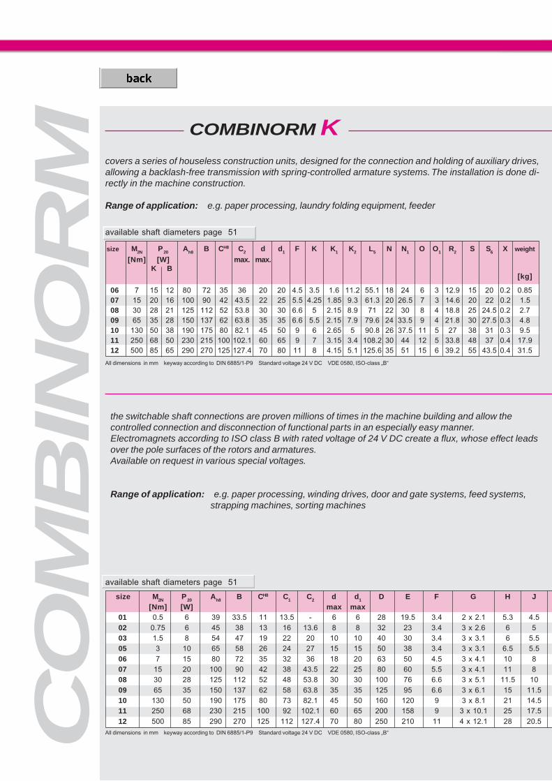
COMBINORM K
the switchable shaft connections are proven millions of times in the machine building and allow thecontrolled connection and disconnection of functional parts in an especially easy manner.Electromagnets according to ISO class B with rated voltage of 24 V DC create a flux, whose effect leadsover the pole surfaces of the rotors and armatures.Available on request in various special voltages.
Range of application: e.g. paper processing, winding drives, door and gate systems, feed systems,strapping machines, sorting machines
covers a series of houseless construction units, designed for the connection and holding of auxiliary drives,allowing a backlash-free transmission with spring-controlled armature systems. The installation is done di-rectly in the machine construction.
Range of application: e.g. paper processing, laundry folding equipment, feeder
size M2N P 20 Ah8 B CH8 C1 C2 d d1 D E F G H J
[Nm] [W] max max01 0.5 6 39 33.5 11 13.5 - 6 6 28 19.5 3.4 2 x 2.1 5.3 4.502 0.75 6 45 38 13 16 13.6 8 8 32 23 3.4 3 x 2.6 6 503 1.5 8 54 47 19 22 20 10 10 40 30 3.4 3 x 3.1 6 5.505 3 10 65 58 26 24 27 15 15 50 38 3.4 3 x 3.1 6.5 5.506 7 15 80 72 35 32 36 18 20 63 50 4.5 3 x 4.1 10 807 15 20 100 90 42 38 43.5 22 25 80 60 5.5 3 x 4.1 11 808 30 28 125 112 52 48 53.8 30 30 100 76 6.6 3 x 5.1 11.5 1009 65 35 150 137 62 58 63.8 35 35 125 95 6.6 3 x 6.1 15 11.510 130 50 190 175 80 73 82.1 45 50 160 120 9 3 x 8.1 21 14.511 250 68 230 215 100 92 102.1 60 65 200 158 9 3 x 10.1 25 17.512 500 85 290 270 125 112 127.4 70 80 250 210 11 4 x 12.1 28 20.5
size M2N P 20 Ah8 B CH8 C2 d d1 F K K1 K2 L5 N N1 O O1 R2 S S6 X weight
[Nm] [W] max. max.K B
[kg]
06 7 15 12 80 72 35 36 20 20 4.5 3.5 1.6 11.2 55.1 18 24 6 3 12.9 15 20 0.2 0.8507 15 20 16 100 90 42 43.5 22 25 5.5 4.25 1.85 9.3 61.3 20 26.5 7 3 14.6 20 22 0.2 1.508 30 28 21 125 112 52 53.8 30 30 6.6 5 2.15 8.9 71 22 30 8 4 18.8 25 24.5 0.2 2.709 65 35 28 150 137 62 63.8 35 35 6.6 5.5 2.15 7.9 79.6 24 33.5 9 4 21.8 30 27.5 0.3 4.810 130 50 38 190 175 80 82.1 45 50 9 6 2.65 5 90.8 26 37.5 11 5 27 38 31 0.3 9.511 250 68 50 230 215 100 102.1 60 65 9 7 3.15 3.4 108.2 30 44 12 5 33.8 48 37 0.4 17.912 500 85 65 290 270 125 127.4 70 80 11 8 4.15 5.1 125.6 35 51 15 6 39.2 55 43.5 0.4 31.5
All dimensions in mm keyway according to DIN 6885/1-P9 Standard voltage 24 V DC VDE 0580, ISO-class „B“
All dimensions in mm keyway according to DIN 6885/1-P9 Standard voltage 24 V DC VDE 0580, ISO-class „B“
available shaft diameters page 51
available shaft diameters page 51
27
��5#-
�2�
�����
6���
�*�
��
�
��� 5#
��
�*��#
�2
$%
�*�
��
�
�*�#
��
��
�
.��
��
�
-&��
��'��
��
6���
.�
�2
-
�*�
1
��
0�
1
-�
�*�
��
�
��5#
�*�#
��
��
���
�
�
.
�*
�2 �
�/
�"
��
��
��
��
��'��
CO
MB
INO
RM
...03.110 ...03.130
...04.170
COMBINORM C
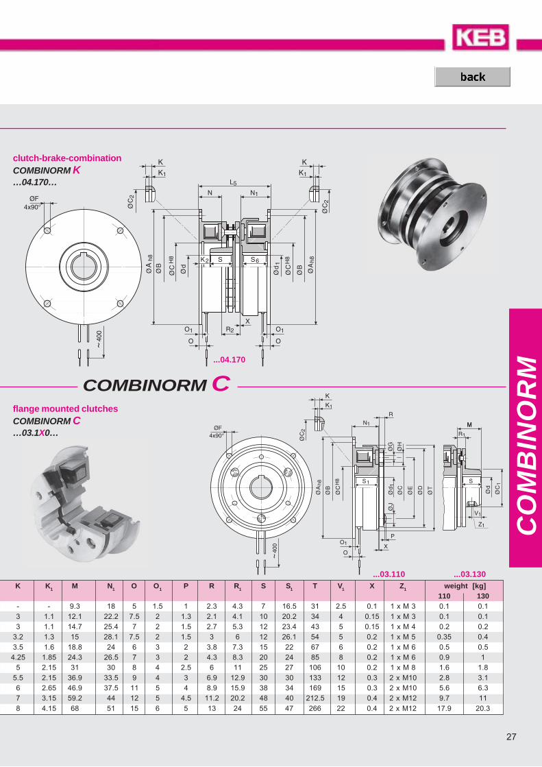
K K1 M N1 O O1 P R R1 S S1 T V1 X Z1 weight [kg]110 130
- - 9.3 18 5 1.5 1 2.3 4.3 7 16.5 31 2.5 0.1 1 x M 3 0.1 0.13 1.1 12.1 22.2 7.5 2 1.3 2.1 4.1 10 20.2 34 4 0.15 1 x M 3 0.1 0.13 1.1 14.7 25.4 7 2 1.5 2.7 5.3 12 23.4 43 5 0.15 1 x M 4 0.2 0.2
3.2 1.3 15 28.1 7.5 2 1.5 3 6 12 26.1 54 5 0.2 1 x M 5 0.35 0.43.5 1.6 18.8 24 6 3 2 3.8 7.3 15 22 67 6 0.2 1 x M 6 0.5 0.54.25 1.85 24.3 26.5 7 3 2 4.3 8.3 20 24 85 8 0.2 1 x M 6 0.9 1
5 2.15 31 30 8 4 2.5 6 11 25 27 106 10 0.2 1 x M 8 1.6 1.85.5 2.15 36.9 33.5 9 4 3 6.9 12.9 30 30 133 12 0.3 2 x M10 2.8 3.16 2.65 46.9 37.5 11 5 4 8.9 15.9 38 34 169 15 0.3 2 x M10 5.6 6.37 3.15 59.2 44 12 5 4.5 11.2 20.2 48 40 212.5 19 0.4 2 x M12 9.7 118 4.15 68 51 15 6 5 13 24 55 47 266 22 0.4 2 x M12 17.9 20.3
clutch-brake-combinationCOMBINORM K…04.170…
flange mounted clutchesCOMBINORM C…03.1X0…

CO
MB
INO
RM
COMBINORM C
.�
�2
-
�*�
1
��
0�
.�
�2 &
-%
�*��5!
$�
1�
-�
��
.
�%�
�
�*
�"
��
��
��
�/
��
0������
��
��
�2 �
��
��
7
6���
��
...03.610 ...03.630 ...03.640
size M2N P 20 B1 C C1 C4 d d2 d6 D E F1 G H J L4 M M1
[Nm] [W] max max max
01 0.5 6 16.8 11 13.5 13 6 6 6 28 19.5 3.1 2 x 2.1 5.3 4.5 4.8 9.3 9.3
02 0.75 6 20 13 16 14 8 6 6 32 23 3.1 3 x 2.6 6 5 7.8 12.1 12.1
03 1.5 8 23 19 22 18 10 10 10 40 30 3.1 3 x 3.1 6 5.5 9.1 14.7 14.7
05 3 10 28 26 24 28 15 17 15 50 38 3.1 3 x 3.1 6.5 5.5 8.8 15 15
06 7 15 36 35 32 - 18 20 - 63 50 5.2 3 x 4.1 10 8 - 18.8 -
07 15 20 45 42 38 - 22 25 - 80 60 5.2 3 x 4.1 11 8 - 24.3 -
size M2N P20 Ah8 A1 B B1 C C1 d d3 D D2 E E1 F F1 G
[Nm] [W] max max
06 7 15 80 - 72 - 35 32 18 17 63 - 50 - 4.5 - 3 x 4.1
07 15 20 100 - 90 - 42 38 22 22 80 - 60 - 5.5 - 3 x 4.1
08 30 28 - 62.5 - 56 52 48 30 30 100 85 76 45.75 - 6.5 3 x 5.1
09 65 35 - 75 - 68.5 62 58 35 35 125 95 95 55 - 6.5 3 x 6.1
10 130 50 - 95 - 87.5 80 73 45 50 160 126 120 72.5 - 9 3 x 8.1
11 250 68 - 115 - 107.5 100 92 60 50 200 126 158 88 - 9 3 x 10.1
12 500 85 - 145 - 135 125 112 70 60 250 160 210 110 - 11 4 x 12.1
shaft mounted clutches size 01 ... 07COMBINORM C…03.6X0…
table (1)
table (2)
table (1)
All dimensions in mm keyway according to DIN 6885/1-P9 Standard voltage 24 V DC VDE 0580, ISO-class „B“
available shaft diameters page 51
29
��
���
�
��
��
��
��
�
��
�
�
��
��
��
��
�
��
��
��
��
��
�
��
��
��
�� �
��
��
�
�� ��
��
�
��
��
���������
�
�
��
��
�����
CO
MB
INO
RM
...03.230 ...03.210
...03.730 ...03.710
size M2N1) P
20 B1 C C1 C4 d d2 d6 D E F1 G H J L4 M M1 N2 O5 P P2 P4 Q R R1 S S2 S5 T U V1 X Z Z1 weight
[Nm] [W] max max max 110 [kg] 130
01 0.5 6 16.8 11 13.5 13 6 6 6 28 19.5 3.1 2 x 2.1 5.3 4.5 4.8 9.3 9.3 17.3 3.6 1 1.5 8 3 2.3 4.3 7 23.5 9.4 31 17 2,5 0.1 M3 M3 0.1 0.1
02 0.75 6 20 13 16 14 8 6 6 32 23 3.1 3 x 2.6 6 5 7.8 12.1 12.1 19.8 5 1.3 1.5 8 3 2.1 4.1 10 26.2 12.25 34 21 4 0.15 M3 M3 0.1 0.1
03 1.5 8 23 19 22 18 10 10 10 40 30 3.1 3 x 3.1 6 5.5 9.1 14.7 14.7 23 5.1 1.5 1.5 8 3 2.7 5.3 12 30.4 14.85 43 23 5 0.15 M4 M4 0.2 0.2
05 3 10 28 26 24 28 15 17 15 50 38 3.1 3 x 3.1 6.5 5.5 8.8 15 15 26.1 7.8 1.5 1.5 8 3 3 6 12 34.1 15.2 54 32 5 0.2 M4 M5 0.35 0.4
06 7 15 36 35 32 - 18 20 - 63 50 5.2 3 x 4.1 10 8 - 18.8 - 24 6 2 2.5 12 7 3.8 7.3 15 33 - 67 41 6 0.2 M4 M6 0.5 0.5
07 15 20 45 42 38 - 22 25 - 80 60 5.2 3 x 4.1 11 8 - 24.3 - 26.5 7 2 2.5 12 7 4.3 8.3 20 38 - 85 50 8 0.2 M6 M6 0.9 1
size M2N1) P20 Ah8 A1 B B1 C C1 d d3 D D2 E E1 F F1 G H J M O2 P P3 P4 P5 R R1 S S3 T V V1 W W1 X Z1 weight
[Nm] [W] max max 210 [kg] 230
710 730
06 7 15 80 - 72 - 35 32 18 17 63 - 50 - 4.5 - 3 x 4.1 10 8 18.8 19 2 - - 4 3.8 7.3 15 41 67 - 6 - - 0.2 1xM6 0.8 0.9
07 15 20 100 - 90 - 42 38 22 22 80 - 60 - 5.5 - 3 x 4.1 11 8 24.3 21.5 2 - - 4.5 4.3 8.3 20 45 85 - 8 - - 0.2 1xM6 1.5 1.6
08 30 28 - 62.5 - 56 52 48 30 30 100 85 76 45.75 - 6.5 3 x 5.1 11.5 10 31 24 2.5 16.2 12 5.5 6 11 25 51.5 106 M5 10 M4 46.5 0.2 1xM8 2.3 2.5
09 65 35 - 75 - 68.5 62 58 35 35 125 95 95 55 - 6.5 3 x 6.1 15 11.5 36.9 25 3 18.7 14 5.5 6.9 12.9 30 55 133 M8 12 M5 55 0.3 2xM10 3.7 4.1
10 130 50 - 95 - 87.5 80 73 45 50 160 126 120 72.5 - 9 3 x 8.1 21 14.5 46.9 31.5 4 21.5 14 7 8.9 15.9 38 65 169 M8 15 M5 72.5 0.3 2xM10 7 7.7
11 250 68 - 115 - 107.5 100 92 60 50 200 126 158 88 - 9 3 x 10.1 19 17.5 59.15 32.5 4.5 23 20 7 11.15 20.15 48 71 212.5 M10 19 M6 88 0.4 2xM12 13.1 14.3
12 500 85 - 145 - 135 125 112 70 60 250 160 210 110 - 11 4 x 12.1 28 20.5 68 41 5 27 22 8 13 24 55 85 266 M10 22 M8 110 0.4 2xM12 23 25
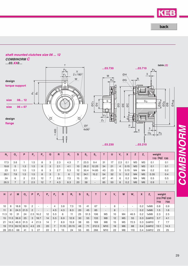
shaft mounted clutches size 06 ... 12COMBINORM C…03.XX0…
table (1)
design
fl ange
design
torque support
table (2)
All dimensions in mm keyway according to DIN 6885/1-P9 Standard voltage 24 V DC VDE 0580, ISO-class „B“ 1) rated torque after running in process
size 08... 12
size 06 + 07

��
6���
��"�
�"
��
��
��
��
�����#���
�
�
��
��
-�
��
��5#
��
���
��2
����8&
���
��
�2 !
�/
��
�
�� �%
���
$�
$�
$
COMBINORM C
CO
MB
INO
RM
...03.810
size M2N P 20 MA
1) Ah8 A1 B B1 C5 D D2 D3 D4 d4 d7 d E E1 E2 F F1 G H J[Nm] [W] [Nm] max max
06 7 15 10 80 - 72 - 30 63 - 25 29 19 17 16 50 - 44 4x4.5 - 3x4.1 10 807 15 20 25 100 - 90 - 40 80 - 35 40 26 25 22 60 - 68 4x5.5 - 3x4.1 11 808 30 28 25 - 62.5 - 56 45 100 85 40 46 30 28.5 25 76 45.75 80 - 6.5 3x5.1 11.5 1009 65 35 50 - 75 - 68.5 60 125 95 50 57 38 33 35 95 55 100 - 6.5 3x6.1 15 11.510 130 50 140 - 95 - 87.5 85 160 126 70 76 55 41 50 120 72,5 140 - 9 3x8.1 21 14.511 250 68 220 - 115 - 107.5 100 200 126 70 76 65 48 50 158 88 165 - 9 3x10.1 25 17.512 500 85 500 - 145 - 135 125 250 160 80 89 85 52 60 210 110 215 - 11 4x12.1 28 20.5
size 08... 12
size 06 + 07
shaft mounted clutches with bearing take-up for the outputCOMBINORM C…03.810…
For flexible clutches (type ...03.840) the following additional instructions are applicable:
The radial and axial screws connecting the rubber element to the hubs must all be tightened to the torque(M
A) given in the table, using a torque wrench.
Ensure that when tightening the screws the aluminium bushes do not twist in the rubber part and that theysit squarely. In order to reduce friction between the screw head and the aluminium bush smear a smallamount of grease under the head of the screw before fitting. If necessary use a suitable tool to applycounter pressure on the element to prevent twisting of the rubber part while tightening the screws. This isparticularly important with the radial screws otherwise the curved faces between the aluminium bush andthe hub will not engage on the full area but only across the two sides. This will inevitably lead to slackeningof the screws and destruction of the clutch. If the clutch is supplied in a pre-assembled state, do notdismantle it, but fit it in this condition.
All dimensions in mm keyway according to DIN 6885/1-P9 Standard voltage 24 V DC VDE 0580, ISO-class „B“ 1) tightening torque for W2
designflange
designtorque support
available shaft diameters page 51

31
CO
MB
INO
RM
6���
�
�"�
��� -�
�2 �
�*%
�2
$�
1�
��
0������
1�
��1�
/�
�2 !
...03.840
size Compliance [mm] of flexible clutches
radial axial
06 1.5 207 1.5 308 1.5 309 2 410 2 511 2 512 2 5
shaft mounted clutches with flexible clutchesCOMBINORM C…03.840…
J3 K3 L L1 L2 L3 M2 M3 M4 O1 O2 P P3 P4 P5 S3 T T1 V W W1 W2 X Z weight kg]
810 840
2 1.3 32.9 25.6 80 117 30 24 19 3 19 2 - - 4 41 67 56 - - - 2 x M 6 0.2 M 5 1 1.74 1.6 37.7 29.9 90 129 30 24 20 3 21.5 2 - - 4.5 45 85 85 - - - 2 x M 8 0.2 M 6 1.8 34 1.85 35.2 32.15 96 141 35 28 23 - 24 2.5 16.2 12 5.5 51.5 106 100 M 5 M 4 46.5 3 x M 8 0.2 M 8 2.7 4.14 2.15 37.6 34.6 103 160 45 32 31 - 25 3 18.7 14 5.5 55 133 120 M 8 M 5 55 3 x M10 0.3 M 10 4.2 7.46 2.65 47.8 43.1 126 200 60 46 40 - 31.5 4 21.5 14 7 65 169 170 M 8 M 5 72.5 3 x M14 0.3 M 10 8.3 14.68 2.65 47.5 43.3 134 217 65 58 40 - 32.5 4.5 23 20 7 82 212.5 200 M10 M 6 88 3 x M16 0.4 M 12 14.5 24.48 2.65 59.6 55.3 162 260 80 70 49 - 41 5 27 22 8 85 266 260 M10 M 8 110 3 x M20 0.4 M 12 26 45.2
size 08... 12
size 06 + 07
designflange
designtorque support
COMBINORM T
CO
MB
INO
RM
�
6���
.�
�2
-
�*�
��
0�
1%
-�
�*�
��
�
��5#
�*�#
��
��
���
�
�
.�
�2 �
�/
�"
��
���
��
���
.
...07.110 ...07.130
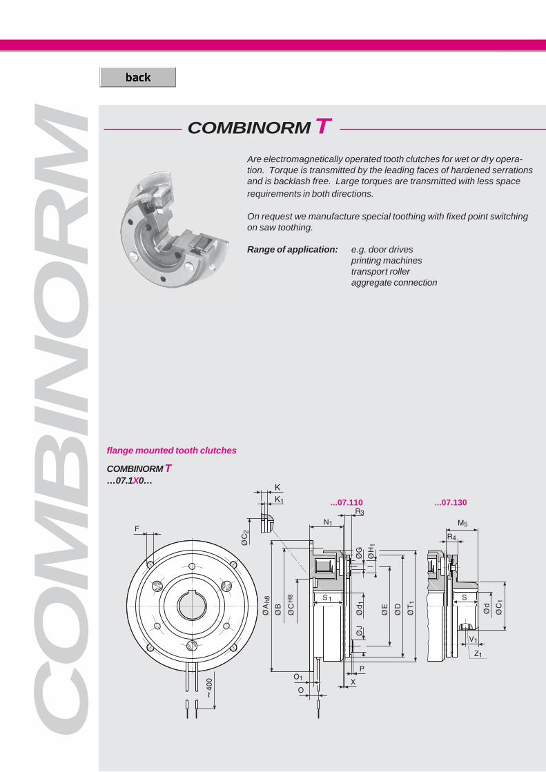
COMBINORM T…07.1X0…
Are electromagnetically operated tooth clutches for wet or dry opera-tion. Torque is transmitted by the leading faces of hardened serrationsand is backlash free. Large torques are transmitted with less spacerequirements in both directions.
On request we manufacture special toothing with fixed point switchingon saw toothing.
Range of application: e.g. door drivesprinting machinestransport rolleraggregate connection
flange mounted tooth clutches

33
��
6���
��
"�
-�
��
.�
��5#
��
���
��*
�"
��
���
�2 �
�/
��
�
�� �%
���
��
��
�����#���
�
��
��
��
.�
�2
-
�*�
1%
��
0�
...07.730 ...07.710
...07.230 ...07.210
COMBINORM T…07.XX0…
CO
MB
INO
RM
size R3 R4 S S1 S3 T1 V V1 W W1 X Z1 weight [kg]
210/710 230/730 110 130
06 5.3 8.8 15 22 41 68 - 6 - - 0.15 1 x M 6 1 1 0.7 0.7
07 6.4 10.4 20 24 45 86.5 - 8 - - 0.2 1 x M 6 1.7 1.8 1.1 1.2
08 8.6 13.6 25 27 51.5 108 M5 10 M 4 46.5 0.2 1 x M 8 2.6 2.8 1.9 2.1
09 11.2 17.2 30 30 55 135 M8 12 M 5 55 0.2 2 x M10 4.1 4.4 3.2 3.5
10 12.8 19.8 38 34 65 172.2 M8 15 M 5 72.5 0.25 2 x M10 7.5 8.3 6.1 6.9
size M2N P 20°C Ah8 A1 B B1 C H8 C1 C2 D d1 D2 d3 d E E1
[Nm] [W] max max max
06 21 15 80 - 72 - 35 32 36 63 20 - 17 18 50 -
07 45 20 100 - 90 - 42 38 43.5 80 25 - 22 22 60 -
08 90 28 125 62.5 112 56 52 48 53.8 100 30 85 30 30 76 45.75
09 195 35 150 75 137 68.5 62 58 63.8 125 35 95 35 35 95 55
10 390 50 190 95 175 87.5 80 73 82.1 160 50 126 50 45 120 72.5
shaft mounted tooth clutches
size 08... 10
size 06 + 07
All dimensions in mm keyway according to DIN 6885/1-P9 Standard voltage 24 V DC VDE 0580, ISO-class „B“
designflange
designtorque support
available shaft diameters page 51
size F F1 G H1 J K K1 M5 N1 O O1 O2 P P3 P4 P5
06 4x4,5 - 3x4.1 8 8 3,5 1.6 20.3 24 6 3 19 2 - - 4
07 4x5,5 - 3x4.1 8 8 4.25 1.85 26.4 26.5 7 3 21.5 2 - - 4.5
08 4x6,6 6.5 3x5.1 11.2 10 5 2.15 33.6 30 8 4 24 2,5 16.2 12 5.5
09 4x6,6 6.5 3x6.1 15 11.5 5.5 2.15 41.2 33.5 9 4 25 3 18.7 14 5.5
10 4x9 9 3x8.1 16 14.5 6 2.65 50.8 37.5 11 5 31.5 4 21.5 14 7

CO
MB
INO
RM
LegendM2N static rated torque [Nm]Merf required torque [Nm]J moment of inertia [10-4kgm2]P20 power at 20° C [W]nmax maximum speed [min-1]X rated air gap [mm]Xn clearance at which an adjustment is recommended [mm]WRmax permissible friction per switching operation [104J]WR0,1 friction work up to 0,1 mm wear [107J]PRmax permissible friction work per second [J/s]I magnet-rated current [A]t time [ms]
t1 Engaging time Time from connecting thethe rated torque is attained
t11 Engaging delay time: Time from conneccurrent until the torque rises
t2 Release time: Time from disconnecting tuntil 0.1 M2N
Combinorm 02 / 03 / 04 / 07size 01 02 03 05 06 07 08M2N 02/03/04 20° [Nm] 0.5 0.75 1.5 3 7 15 30
07 21 45 90
P20 02/04 brake 20° [W] 6 6 8 10 12 16 21
03/04/07 clutch 20° 6 6 8 10 15 20 28
J
armature 110/210/610/710/810 [10-4kgm2] 0.010 0.014 0.045 0.122 0.366 1.07 3.72
120/130/230/630/730 0.013 0.021 0.068 0.18 0.53 1.57 5.29
320 0.82 2.6 10.3
170 0.99 2.7 9.12
Rotor 110/130/140/170/610 0.025 0.035 0.15 0.375 0.825 2.38 7.25
630/640
210/230/240/710/730/740 0.027 0.038 0.17 0.4 0.9 2.6 8
810 1.02 3.05 8.76
WR max. 02/03/04 [104J] 0.04 0.05 0.08 0.12 0.19 0.31 0.48
WR 0,1mm 02/03/04 [107J] 0.23 0.3 0.43 0.63 0.95 1.63 2.53
PR max. 02/04 brake [J/s] 12.8 18.6 26.9 38.9 58.3 79.2 114
03/04 clutch 20.3 28.6 40.6 58.3 80.6 114 161
Xnmax. 20° 02/03/04 [mm] 0.3 0.45 0.45 0.6 0.7 0.7 0.7
07 0.15 0.2 0.2
X 02/03/04 0.1 0.15 0.15 0.2 0.2 0.2 0.2
02/03/04/07 [rpm] 10000 10000 10000 10000 8000 6000 5000
nmax. exception clutch! 1500 1500 1500 1500 1500 1500
03.610/630/640
switching times
brake 02/04 t2 DC [ms] 3 4 5 8 10 15 50
t2 AC 17 20 25 40 70 95 240
rated torque t11 = 2 3 3 5 6 8 10
t1 = 5 8 8 17 24 38 42
3 x rated torque t11 = 1 2 2 3 3 4 5
t1 = 3 4 4 8 11 17 20
clutch t2 DC [ms] 5 6 7 10 14 19 40
03/04 t2 AC 17 19 22 30 39 61 115
rated torque t11 = 4 5 7 10 14 18 23
t1 = 10 14 17 32 48 74 81
3 x rated torque t11 = 2 2 3 5 6 8 10
t1 = 5 6 7 16 22 33 37
Technical data
35
9
1
1��
�4'1��
:��
:� :�
:
�4�1��
:
COMBINORM
CO
MB
INO
RM
the current[ms]
ecting the[ms]
the current[ms]
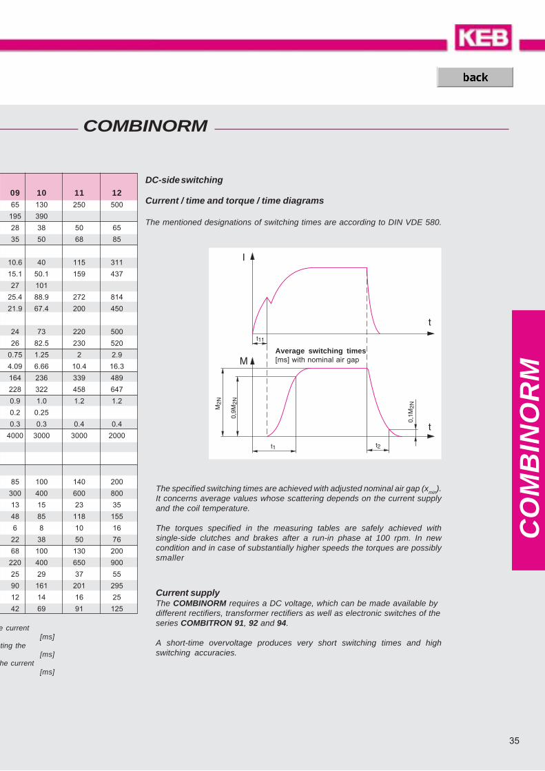
The specified switching times are achieved with adjusted nominal air gap (xmin).It concerns average values whose scattering depends on the current supplyand the coil temperature.
The torques specified in the measuring tables are safely achieved withsingle-side clutches and brakes after a run-in phase at 100 rpm. In newcondition and in case of substantially higher speeds the torques are possiblysmaller
DC-side switching
Current / time and torque / time diagrams
The mentioned designations of switching times are according to DIN VDE 580.
09 10 11 1265 130 250 500
195 390
28 38 50 65
35 50 68 85
10.6 40 115 311
15.1 50.1 159 437
27 101
25.4 88.9 272 814
21.9 67.4 200 450
24 73 220 500
26 82.5 230 520
0.75 1.25 2 2.9
4.09 6.66 10.4 16.3
164 236 339 489
228 322 458 647
0.9 1.0 1.2 1.2
0.2 0.25
0.3 0.3 0.4 0.4
4000 3000 3000 2000
85 100 140 200
300 400 600 800
13 15 23 35
48 85 118 155
6 8 10 16
22 38 50 76
68 100 130 200
220 400 650 900
25 29 37 55
90 161 201 295
12 14 16 25
42 69 91 125
Average switching times[ms] with nominal air gap
Current supplyThe COMBINORM requires a DC voltage, which can be made available bydifferent rectifiers, transformer rectifiers as well as electronic switches of theseries COMBITRON 91, 92 and 94.
A short-time overvoltage produces very short switching times and highswitching accuracies.
CO
MB
IBO
X
360 / 370 380 / 390 460 / 470 440
570 / 580 410 / 430 450 / 480 670
490 500 510 520
530 / 540 550 / 560 590 / 600 610
620 / 630 640 / 660 680 / 690 700 800
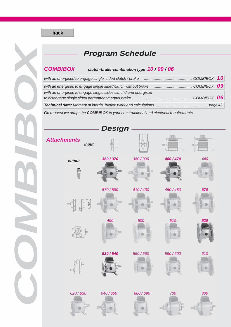
COMBIBOX clutch-brake-combination type 10 / 09 / 06
with an energised to engage single sided clutch / brake ............................................ COMBIBOX 10with an energised to engage single sided clutch without brake ................................... COMBIBOX 09with an energised to engage single sides clutch / and energisedto disengage single sided permanent magnet brake ....................................................... COMBIBOX 06Technical data: Moment of inertia, friction work and calculations ................................................. page 42
On request we adapt the COMBIBOX to your constructional and electrical requirements.
Program Schedule
Design
Attachmentsinput
output

37
CO
MB
IBO
X
The COMBIBOX is a ready to install electromagnetic actuated clutch-brake module in a single housing.The modular system is designed for a multitude of variants; thesecovering most of the applications in the field.The patented adjustment procedure permits an air gap re-adjustment init’s installed condition. Thus giving a greater lifetime of the wear af-fected components.
The units designed for Start-Stop-operation considerably reduce theenergy consumption due to a continuously running drive.
has an energise to engage single sided brake, this is the most commonly used, permit-ting high switching frequency and good positioning accuracy. The COMBITRON rapidswitch can be used with this variant to achieve expectionally high switching frequencies.The rated torque of both clutch and brake are identical.
type 10
type 09
type 06
has an energise to disengage permanent magnet single-side brake. The charac-teristic of this variant is that the position of the output shaft is kept safe and backlash-free in currentless condition. The rated torque of the brake is slightly lower than that ofthe clutch.
is the COMBIBOX versionwithout brake , i.e. an electrical clutch in a housing for theuse between e.g. motor and gear unit.

CO
MB
IBO
X ;�<
�2�
�
;��<= >%
�?
��< ��<
) (@
��
� �
���
�@�
�>
5�
�>� ! �
@�
��!
5
V DC, Ø a1, Ø d1 ?
variations type 06 (marked in red)
flange B5 (1) flange B5 (1)
size 06 07 08 09 10 11
M2N [Nm] clutch 7 15 30 65 130 250 / -
brake 7 / 6 15 / 12 30 / 24 65 / 50 130 / 120 250 / -
P20 [W] clutch 15 20 28 35 50 68 / -
brake 12 / 13 16 / 21 21 / 20 28 / 30 38 / 50 50 / -
size a3 a4 a7 b c e f2 f5 g h h1 i k k1 n s s2 ushaft weight
d1 I [kg]
06 80 100/109 85 115/124 3 72 100 10 103 63 87 18.4 137/146 117/126 18 7 M6 4411 23
2.8/2.914 30
07 105 115/125 110 138/148 3 90 130 10 125 71 94 22.7 160/170 140/150 25 9 M8 5014 30
3.9/4.119 40
08 130 135/147 140 160/172 4 112 160 12 158 90 108 30.6 196/208 172/184 28 9 M8 6219 40
7.7/8.724 50
09 150 155/169 160 180/194 5 137 180 14 185 100 129 34.4 224/238 196/210 30 11 M10 7424 50
12.5/15.028 60
10 185 185/202 195 215/232 6 175 223 18 236 132 154 50.6 286/303 250/267 38 13 M12 95 28 60 22.5/28.0
11 upon request
rated torques 10 / 09 / 06
part no. feet flange flangeinput outputB5 (1) B5 (1)
— — . — — . 360— — . — — . 370 X— — . — — . 380 X— — . — — . 390 X X— — . — — . 410 X X— — . — — . 430 X X X— — . — — . 570 X— — . — — . 580 X X
designtypesize
ordering specification:– part number– diameter of input-side flange– diameter of input-side shaft– diameter of output-side bore– diameter of output-side flange– operating voltage of COMBIBOX– flange dimensions on page 43
designsizetype
COMBIBOX shaft in / shaft out
all dimensions in mm keyways according to DIN 6885/1 centerings D according DIN 332/2 Standard voltage 24 V DC VDE 0580, ISO-class „B“
Ordering example:06. 10. 430
flange dimensions page 43
output input

39
CO
MB
IBO
X
@�
�
��
� �
���
>�
;��<
=�>&
�A
�2��<
���
�2�
��< ��<
@)
=� =�
��
� &
���
>!
�&
�@%�@&
B5 (2) B14 (3)
V DC, Ø a6, Ø d2, Ø a6,Ø d3 ?
size g h h1 k4 l1 l2 l3 n s s6 v aaaaa weight
[kg]
06 103 63 87 101 / 110 50 57 9 18 7 5.5 30 60 2.7 / 3.1
07 125 71 94 108 /118 52 61 9 25 9 6.5 35 60 3.7 / 4.5
08 158 90 108 132 / 144 63.5 75 11 28 9 8.5 45 64 7.5 / 8.9
09 185 100 129 153 / 167 74 86 13 30 11 8.5 50 62 12.0 / 14.5
10 236 132 154 175 / 232 86 102 17 38 13 10.5 70 60 20 / 25.5
11 upon request
size a3 a4 a5 a7 b b c d2 d3 e3 f2 f6
h8 G7max G7max
06 80 100/109 104 85 115/124 60 3 15 15 108 100 4 11 or 14
07 105 115/125 123 110 138/148 70 3 24 24 128 130 4 14 or 19
08 130 135/147 155 140 160/172 80 4 28 28 165 160 4 19 or 24
09 150 155/169 178 160 180/194 95 5 35 35 190 180 5 24 or 28
10 185 185/202 229 195 215/232 110 6 42 42 242 223 5 28
11 upon request
ordering specifications:– part number– diameter of input-side flange– diameter of input-side shaft– diameter of output-side shaft– diameter of output-side flange– operating voltage of COMBIBOX– flange dimensions page 43
designsizetype
part no. feet flange flangeinput output
B5(2) B14(3) B5(2) B14(3)— — . — — . 510 X X— — . — — . 520 X X— — . — — . 590 X X— — . — — . 600 X X X— — . — — . 610 X X— — . — — . 680— — . — — . 690 X— — . — —.
designtypesize
flange B14 (3) flange B5 (2)
COMBIBOX bore in / bore out
flange dimensions page 43
variations type 06 (marked in red)
all dimensions in mm keyways according to DIN 6885/1 centerings D according DIN 332/2 Standard voltage 24 V DC VDE 0580, ISO-class „B“
Preferential-bored2 and d3
Ordering example:06. 10. 600
output input

CO
MB
IBO
X
V DC, Ø a6, Ø d2, Ø a1, Ø d1 ?
size a3 a4 a5 a7 b b4 c d2+3 e e3 f2 f5 f6 gh8 G7 max
06 80 100/109 104 85 115/124 60 3 15 72 108 100 10 4 103
07 105 115/125 123 110 138/148 70 3 24 90 128 130 10 4 125
08 130 135/147 155 140 160/172 80 4 28 112 165 160 12 4 158
09 150 155/169 178 160 180/194 95 5 35 137 190 180 14 5 185
10 185 185/202 229 195 215/232 110 6 42 175 242 223 18 5 236
11 upon request
part no. feet input output flange flange
B5(2) B14(3) B5(1)— — . — — . 440 X— — . — — . 450 X X— — . — — . 460 X— — . — — . 470 X X— — . — — . 480 X X X— — . — — . 640— — . — — . 660 X— — . — — . 670 X X
designtypesize
ordering specifications:– part no.– diameter of input-side flange– diameter of input-side shaft– diameter of output-side bore– diameter of output-side flange– operating voltage of COMBIBOX– flange dimensions on page 43
designsizetype
flange B5 (2) flange B14 (3)
all dimensions in mm keyways according to DIN 6885/1 centerings D according DIN 332/2 Standard voltage 24 V DC VDE 0580, ISO-class „B“
COMBIBOX bore in / shaft out
flange dimensions on page 43
flange B5 (1)
ordering example:06. 10. 450
size 06 07 08 09 10 11
M2N [Nm] clutch 7 15 30 65 130 250 / -
brake 7 / 6 15 / 12 30 / 24 65 / 50 130 / 120 250 / -
P20 [W] clutch 15 20 28 35 50 68 / -
brake 12 / 13 16 / 21 21 / 20 28 / 30 38 / 50 50 / -
rated torques 10 / 09 / 06
all dimensions in mm keyways according to DIN 6885/1 centerings D according DIN 332/2 Standard voltage 24 V DC VDE 0580, ISO-classe „B“
output input

41
CO
MB
IBO
X
V DC, Ø a1, Ø d1, Ø a2, Ø d3 ?
part no. feet input outputflange flangeB5(1) B5(2) B14(3)
— — . — — . 490 X— — . — — . 500 X X— — . — — . 530 X— — . — — . 540 X X— — . — — . 550 X X— — . — — . 560 X X X— — . — — . 620— — . — — . 630 X
designtypesize
flange B14 (3) flange B5 (2)
variations type 06 (marked in red)
ordering specifications:– part no.– diameter of input-side flange– diameter of input-side shaft– diameter of output-side bore– diameter of output-side flange– operating voltage of COMBIBOX– flange dimensions on page 43
designsizetype
shaft weighth h1 i k2 l1 l3 n s s2 s6 u v aaaaa d1 l [kg]
h8 k611 2363 87 18.4 119/128 50 9 18 7 M6 5.5 44 30 60 11 or 14 14 30 2.8/3.1
14 3071 94 22.7 134/144 52 9 25 9 M8 6.5 50 35 60 14 or 19 19 40 3.9/4.5
19 4090 108 30.6 164/176 63,5 11 28 9 M8 8.5 62 45 64 19 or24 24 50 7.7/8.9
24 50100 129 34.4 189/203 74 13 30 11 M10 8.5 74 50 62 24 or 28 28 60 12.5/14.5
132 154 50.6 231/248 86 17 38 13 M12 10.5 95 70 60 28 28 60 22.5/26.0
COMBIBOX shaft in / bore out
flange dimensions on page 43
Preferentialbored2 and d3
flange B5 (1)
ordering example:06. 10. 500
output input
CO
MB
IBO
X
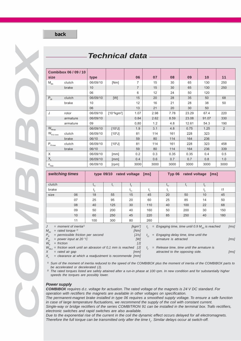
J = moment of inertia1) [kgm2]M2N = rated torque 2) [Nm]PR = permissible friction per second [J/s]P20 = power input at 20 °C [W]WR = friction [J]WR0,1 = friction work until an abrasion of 0,1 mm is reached [J]X = rated air gap [mm]Xn = clearance at which a readjustment is recommende [mm]
Combibox 06 / 09 / 10size type 06 07 08 09 10 11M2N clutch 06/09/10 [Nm] 7 15 30 65 130 250
brake 10 7 15 30 65 130 250
06 6 12 24 50 120
P20 clutch 06/09/10 [W] 15 20 28 35 50 68
brake 10 12 16 21 28 38 50
06 13 21 20 30 50
J rotor 06/09/10 [10-4kgm2] 1.07 2.98 7.78 23.29 67.4 220
armature 06/09/10 0.84 2.62 8.59 23.08 91.07 330
armature 09 0,80 1.2 4.8 12.61 54.3 190
WRmax 06/09/10 [103J] 1.9 3.1 4.8 0.75 1.25 2
WR 0,1mm clutch 06/09/10 [106J] 81 114 161 228 323
brake 06/10 59 80 114 164 236
PR max. clutch 06/09/10 [106J] 81 114 161 228 323 458
brake 06/10 59 80 114 164 236 339
X 06/09/10 [mm] 0.2 0.3 0.35 0.35 0.4 0.5Xn 06/09/10 [mm] 0.4 0.6 0.7 0.7 0.8 1.0
nmax 06/09/10 [rpm] 3000 3000 3000 3000 3000 3000
t1 = Engaging time, time until 0.9 M2N is reached [ms]
t11 = Engaging delay time, time until thearmature is attracted [ms]
t2 = Release time, time until the armature isattracted to the opposing side. [ms]
switching times type 09/10 rated voltage [ms] Typ 06 rated voltage [ms]
clutch t11 t1 t2 t11 t1 t2brake t2 t11 t1 t1 t2 t1
size 06 18 55 15 45 20 50 10 45
07 25 95 20 60 25 85 14 50
08 40 125 30 110 40 100 22 68
09 50 200 40 160 50 200 30 150
10 60 250 45 220 85 250 40 180
11 100 300 80 260
1) Sum of the moment of inertia reduced to the speed of the COMBIBOX plus the moment of inertia of the COMBIBOX parts tobe accelerated or decelerated (J).
2) The rated torques listed are safely attained after a run-in phase at 100 rpm. In new condition and for substantially higherspeeds the torques are possibly lower.
Power supplyCOMBIBOX requires d.c. voltage for actuation. The rated voltage of the magnets is 24 V DC standard. Foroperation with rectifiers the magnets are available in other voltages on specification.The permanent-magnet brake installed in type 06 requires a smoothed supply voltage. To ensure a safe functionin case of large temperature fluctuations, we recommend the supply of the coil with constant current.Single-way or bridge rectifiers of the series COMBITRON 91 can be installed in the terminal box. Trafo rectifiers,electronic switches and rapid switches are also available.Due to the exponential rise of the current in the coil the dynamic effect occurs delayed for all electromagnets.Therefore the full torque can be transmitted only after the time t1. Similar delays occur at switch-off.
Technical data

43
COMBIBOX
CO
MB
IBO
X
1) according DIN IEC 34 standard flange
size IEC Ø1) a1 (1) a2 (2) a6 (3) b1 (1) b2 (2) b3 (3) c1 (1) c2 (2) c3 (3) c6 (3)h8 +0.3 +0.2 H8
06 90 90 105 105 60 60 60 10 10 10 5.5
105 105 105 105 70 70 70 10 10 10 6.5120 120 120 120 80 80 80 10 10 10 6.5140 140 140 140 95 95 95 10 10 12 8.0
160 160 160 160 110 110 110 10 12 12 8.0
07 105 110 120 120 70 70 70 10 10 10 6.5
120 120 120 120 80 80 80 10 10 10 6.5140 140 140 140 95 95 95 10 10 10 6.0160 160 160 110 110 10 12 6.0
200 200 200 130 130 10 14 8.008 120 130 - 160 80 80 12 12 6.5
140 140 160 160 95 95 95 12 12 12 6.0160 160 160 160 110 110 110 12 12 12 6.0200 200 200 200 130 130 130 12 14 14 7.0
250 250 250 - 180 180 12 14
09 140 159 160 160 95 95 95 14 14 14 9.0
160 160 160 160 110 110 110 14 14 14 9.0200 200 200 200 130 130 130 14 14 14
250 250 250 250 180 180 180 14 14 14
10 160 - 200 200 110 110 18 18 9.0
200 210 200 200 130 130 130 18 18 18 8.0250 250 250 180 180 18 18300 300 300 230 230 18 18
350 350 250 20
11 250 250 268 180 180 20 25
300 300 300 230 230 20 25
350 350 350 250 250 20 25
size IEC Ø1) e1 e2 f f1 f7 s3 s4 s5 s6 weight(1 + 2) (3) (1) (2) (3) (2) (1) (3) (3) [kg] (1/2/3)
06 90 75 75 2.5 3 3 M5 5.5 5.5 10 0.16105 85 85 2.5 3.5 3 M6 7.0 6.5 11 0.17120 100 100 3 3.5 3.5 M6 6.5 6.5 11 0.2140 115 115 3 3.5 3.5 M8 9 8.5 14 0.28160 130 130 3.5 4 4 M8 9 8.5 14 0.45
07 105 85 85 2.5 3.5 3 M6 M6 6.5 11 0.21120 100 100 3 3.5 3.5 M6 6.5 6.5 11 0.22140 115 115 3 3.5 3.5 M8 9 9 14 0.3160 130 3.5 4 M8 9 14 0.33200 165 3.5 4 M10 11 18 0.55
08 120 100 100 3 3.5 7 6.5 11 0.45140 115 115 3 3.5 3.5 M8 9 9 14 0.48160 130 130 3.5 4 4 M8 9 9 14 0.5200 165 215 3.5 4 4.5 M10 11 14 18 0.8250 215 4 4.5 M12 14 1.4
09 140 115 115 3 3.5 9 9 15 0.5160 130 130 3.5 4 4 M8 9 9 15 0.55200 165 165 3.5 4 4 M10 11 11 0.63250 215 215 4 4.5 4.5 M12 14 14 0.95
10 160 130 4.5 4.5 M8 9 15 0.9200 165 165 4 4.5 4 M10 11 11 18 1.1250 215 4 4.5 M12 14 1.2300 265 4 5 M12 14 1.25350 300 5 18 6.5
11 250 215 4 4.5 M12 14300 265 4 4.5 M12 14350 300 5 5.5 M16 18

CO
MB
ITR
ON
COMBITRON
COMBITRON Rectifiers and Switches
Half-wave and bridge rectifiers from 0 - 720 V AC ................................page 45 ........COMBITRON 91
Transformer rectifier with capacitors from 12 - 168 W ..........................page 46 ....... COMBINORM 92
Electronic rapid switch up to 50 W ......................................................page 46 ....... COMBINORM 94
Rapid-switching rectifier (for COMBISTOP) ........................................page 47 ....... COMBINORM 98
Technical data
Program Schedule
Switching mode (AC- / DC-side switching) ..........................................page 48
are supply and actuator modules for the electromagnet clutches and brakes. As power supply for DC- or AC-side switching different single-wave and bridge rectifiers as well as rapid switchgear of the seriesCOMBITRON are available.
The rectifiers correspond to the low voltage regulation 73/231/EWG of the European Union.

45
CO
MB
ITR
ON
COMBITRON 91
Uin
275 VAC +0% 500 VAC +0% 600 VAC +0% 720 VAC +0%
switching AC/DC AC/DC AC AC
Uvmax
450 V 900 V 1000 V 1600 V
half wave 02.91.010-CE07 04.91.010-CE07 05.91.010-CE09 06.91.010-CE09
Uout
= 0,45*Uin
IN (45°C) = 1,0A
IN (80°C) = 0,5A
full wave 02.91.020-CE07 04.91.020-CE07
Uout
= 0,9*Uin
IN (45°C) = 2,0A
IN (80°C) = 1,0A
half wave with 02.91.010-CEMV
EMC protection1)
Uout
= 0,45*Uin
IN (45°C) = 1,0A
IN (80°C) = 0,5A
• compact design in a plastic housing
• possible installation into the motor terminal box
• protection against voltage peaks of the switching contacts
• maximal ambient temperature 80° C
1) with internal interference suppession
according to EN 55011/ class A
Uin maximum input voltage
Uvmax maximum switch-off voltage
Uout DC output voltage
AC AC side switching
DC DC side switching
IN (45°C) nominal current at stated
temperature
Rectifiers for power supply of brakes and clutches. AC voltage supply max 720VACfor AC or DC side switching conform to the low voltage regulation 72/231 EWG of theEuropean Union.
Harmful electromagnetic interferences arise at the switching of electromagneticclutches and brakes and other inductive DC consumers. The half-wave rectifier02.91.010-CEMV limits these interferences to class A according to EN 55011.
All other rectifiers are not equipped with measurements to suppress radio interference.This has to be taken into consideration for the planning of the interference suppressionof the plant or the machine. The user is responsible for meeting the EU machine direc-tive.
Nominal voltage magnet Coil voltage tolerance AC voltage supply Type of rectifier
U2 (Uout) U1 (Uin)
24 V DC
105 V DC 93 - 118 230 V AC half wave rectifier (02.91.010-CE07)
205 V DC 182 - 230 230 V AC full wave rectifier (02.91.020-CE07)
180 V DC 162 - 198 400 V AC half wave rectifier (04.91.010-CE07)
CO
MB
ITR
ON
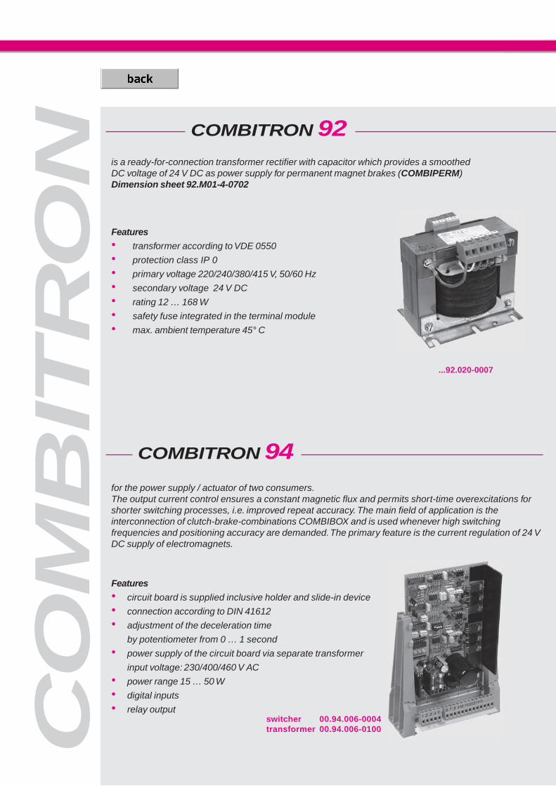
COMBITRON 92
COMBITRON 94
...92.020-0007
for the power supply / actuator of two consumers.The output current control ensures a constant magnetic flux and permits short-time overexcitations forshorter switching processes, i.e. improved repeat accuracy. The main field of application is theinterconnection of clutch-brake-combinations COMBIBOX and is used whenever high switchingfrequencies and positioning accuracy are demanded. The primary feature is the current regulation of 24 VDC supply of electromagnets.
Features
• circuit board is supplied inclusive holder and slide-in device
• connection according to DIN 41612
• adjustment of the deceleration time
by potentiometer from 0 … 1 second
• power supply of the circuit board via separate transformer
input voltage: 230/400/460 V AC
• power range 15 … 50 W
• digital inputs
• relay output
is a ready-for-connection transformer rectifier with capacitor which provides a smoothedDC voltage of 24 V DC as power supply for permanent magnet brakes (COMBIPERM)Dimension sheet 92.M01-4-0702
Features
• transformer according to VDE 0550
• protection class IP 0
• primary voltage 220/240/380/415 V, 50/60 Hz
• secondary voltage 24 V DC
• rating 12 … 168 W
• safety fuse integrated in the terminal module
• max. ambient temperature 45° C
switcher 00.94.006-0004transformer 00.94.006-0100
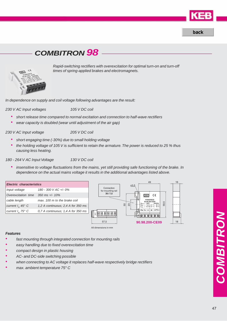
47
CO
MB
ITR
ON
90.98.200-CE09
COMBITRON 98Rapid-switching rectifiers with overexcitation for optimal turn-on and turn-offtimes of spring-applied brakes and electromagnets.
Features
• fast mounting through integrated connection for mounting rails
• easy handling due to fixed overexcitation time
• compact design in plastic housing
• AC- and DC-side switching possible
• when connecting to AC voltage it replaces half-wave respectively bridge rectifiers
• max. ambient temperature 75° C
In dependence on supply and coil voltage following advantages are the result:
230 V AC Input voltages 105 V DC coil
• short release time compared to normal excitation and connection to half-wave rectifiers
• wear capacity is doubled (wear until adjustment of the air gap)
230 V AC Input voltage 205 V DC coil
• short engaging time (-30%) due to small holding voltage
• the holding voltage of 105 V is sufficient to retain the armature. The power is reduced to 25 % thuscausing less heating.
180 - 264 V AC Input Voltage 130 V DC coil
• insensitive to voltage fluctuations from the mains, yet still providing safe functioning of the brake. Independence on the actual mains voltage it results in the additional advantages listed above.
All dimensions in mm
Electric characteristics
Input voltage 180 - 300 V AC +/- 0%
Overexcitation time 350 ms +/- 10%
cable length max. 100 m to the brake coil
current IN 45° C 1,2 A continuous; 2,4 A for 350 ms
current IN 75° C 0,7 A continuous; 1,4 A for 350 ms
Connectionfor mounting rail
35 / 7,5

9�
:
1��
::��:�:�
9
1
��
�
:
*
$ �
��
$ �$ �
�� ��
�� �� ��
��
�
*
$ �
��
$ �$ �
�� ��
�� �� ��
�� ��
CO
MB
ITR
ON
(1)
(2)
t1 = Engagement timet11 = Engagement delay timet2 = Release time
AC-side Switching
When switching before the rectifier on the AC-side the magnetic field decays slowly. At this mode ofswitching the tripping delay is quite long. The AC-side switching requires no protective measurements forthe coil and the switching contacts. On disconnection the rectifier diodes act as free-wheeling diodes.
The switching times t11
for AC-side switching increase when the rectifier is connected directly in the motorterminal box (2). When the motor slows down a generatoric voltage is applied to the motor terminals. Thewiring (2 and 3) is not permitted for frequency inverter operation.
For line lenghts of more than 10 m between rectifier and brake at AC-side switching the regulationsprescribe the use of a separate switch (1). In this case the supply voltage may not be tapped behind themotor contactor (2). If it is not possible to install an additional switch the use of special rectifiersbecomes necessary.
Current-time-/Voltage-time-/Torque-time-diagram Wiring diagram
Switching Arrangements

49
9�
:
1��
::��:�
��
:
�
9
1
:�
*
$ �
��
$ �$ �
�� ��
�� �� ��
��
�
*
*
$ �
��
$ �$ �
�� ��
�� �� ��
�� ��
CO
MB
ITR
ON
(3)
(4)
DC-side switching
The switching is done between the rectifier and the magnet. At his mode of switching the tripping delay isshort, since the energy of the magnetic field is absorbed by the rectifier. The voltage peaks that occur atswitching are limited to a harmless level for the rectifier.
The maximal permissible switching frequency for the DC-side switching of rectifiers depends on theenergy content of the magnet for COMBISTOP. Higher switching frequencies are achieved by the externalconnection of a varistor in parallel to the brake or to the terminals + and - DC of the rectifier.
Rectifier KEB-article varistor02.91. 00.90.045-2752 S20K27504.91. 00.90.045-5101 S20K51005.91. 00.90.045-6252 S20K62506.91. 00.90.045-4202 S20K420*
* 2 components in series
The simultaneous AC and DC-side switching, shown in example 4 guarantees short disconnecting timesand reduces the contact erosion.
Current-time-/Voltage-time-/Torque-time- diagram Wiring diagram

Dimensioning / Calculations
Decisive for the dimensioning of the clutches and brakes are the required torque, thermal load, braking time andservice life.
Rated Torque M2N
To ensure that brakes and clutches work safely even under extreme conditions, the required torque must bemultiplied by a safety factor. The selection of the safety factor depends essentially on the application.The dynamic torque of a single-disc brake may be substantially lower than the rated torque. When choosing thesign take into account whether the load torque supports or counteracts the deceleration.
Required torque Merf
The required torque very often is a mixture of dynamic and static load. When choosing the sign take into accountwhether the load torque supports or counteracts the deceleration.
Rough definition of the required braking torqueIf the mass moment of inertia is unknown and the driving power is fixed then the required braking torque iscalculated as follows:
Thermal loadThe dimensioning solely on the basis of the required braking torque is permissible only in very few cases. Whendecelerating the load and the mass moment of inertia is reduced to the brake shaft, the kinetic energy isconverted into heat (friction work of the brake). The permissible friction work in dependence on the switchingfrequency may not be exceeded. Please note that the maximal permissible friction work is valid only up to thecorresponding speed. In case of emergency stop from maximum speed the maximal permissible friction work liesconsiderably below the values specified in the graphic.
Slip time t3 [ms]The time from the beginning of the torque rise until attaining the moment of synchronization.
Service lifeThe service life depends to a large extent on the peak temperature at braking, which is dependent on the speed,the deceleration time and the current brake torque. For that reason it is not possible to make universally validstatements with regard to the service life that apply to all operating conditions. Statements to the individual casecan be made only when all operating conditions are known. At no time should the friction lining thickness be lessthan gmin.
Acceleration- / Deceleration time
J · Dnt3 = 104,6 · + t11M2N ± ML
J · n2 M2NWR = · WR £ WRmax182,5 M2N ± ML
(Xn-X) · WR0,1LN =
0,1 · WR
PMerf = 9550 ·
n
Merf = MA ± ML
MA = J · a
J · wt = + t1M2N ± ML
M2N = Merf · K K ³ 2 Merf = required torque [Nm]
MAG
NETT
ECHN
IQUE

51
b / c
a P9
d
LegendJ = moment of inertia 1) [kgm2]K = safety factor (K >2) [-]Ln = service life untill readjustment2) [-]Ma = dynamic braking torque [Nm]Merf = required torque [Nm]ML = load torque3) [Nm]M2N = static rated torque 4) [Nm]PR = friction work [J/s]P20 = power input at 20° C [W]t = acceleration / deceleration timet1 = switch-on time [ms]WR = friction [J]WR0,1 = friction work up to 0,1 mm wear [J]S = cycles per second [s-1]w = angular frequency [s-1]X = rated air gap [mm]Xn = clearance at which an adjustment is recommended [mm]
table bores
Deviations COMBIBOX
1) Sum of the moment of inertia reduced to the speed of theCOMBIBOX plus the moment of inertia of the COMBIBOX partsto be accelerated or decelerated.
2) Number of switchings until readjustment. For type 06 and 10the friction WR of the clutch as well as the friction WR of thebrake are to be considered.
3) For the selection of the sign take notice of whether the loadtorque supports or counteracts the acceleration or decelera-tion.
4) The rated torques listed in the tables are safely attained after arun-in phase at 100 rpm. In new condition and for substantiallyhigher speeds the torques are possibly lower.
Rotor Armaturewith bearing
Size12 11 10 09 08 07 06 05 03 02 01 01 02 03 05 06 07 08 09 10 11 12 12 11 10 09 08 07 06 05 03 02 01
Minimum bore Minimum bore Minimum bore(without keyway) (without keyway) (without keyway)
d aP9 b c29 24 16 14 11 9 7 6 - - - - - - - 7 9 11 14 16 24 29 29 24 16 14 11 9 7 7 - - -
5 56 7 6 6 6 67 H8 2 88 9 8 8 8 8 8 89
310,4
10 11,4 10 10 10 10 10 10 10 1011
412,8
12 13,8 12 12 12 12 12 1214 16,3 15,2 14 14 1415 5 17,3 16,2 15 15 15 15 15 15 15 15 1517 19,3 18,2 17 17 17 17 1718 20,8 19,619
621,8 20,6 19 19
20 22,8 21,6 20 20 20 20 20 20 20 20 2022 24,8 23,624 27,3 26,0 2425 8 28,3 27,0 25 25 25 25 25 25 25 2528 31,3 30,0 28 2830 33,3 32,0 30 30 30 30 30 30 30 30 3032 35,3 34,435 H7 10 38,3 37,4 35 35 35 35 35 35 35 3538 41,3 40,4 3840
1243,3 42,2 40 40 40 40 40 40
42 45,3 44,245 48,8 47,1 45 45 45 45 45 4548 14 51,8 50,150 53,8 52,1 50 50 50 50 50 50 50 5055 16 59,3 57,4 55 55 55 5560 18 64,4 62,3 60 60 60 60 6065 69,4 67,3 65 65 6570
2074,9 72,7 70 70
75 79,9 77,780
2285,4 83,1 80
85 90,4 88,190 25 95,4 92,9
d Bore
a P9 keyway with DIN 6885
b Depth over standard keyway DIN 6885/1
c Depth over reduced keyway
available bores „d“ with standard keyway DIN 6885/1
available bores „d“ with reduced keyways DIN 6885/3
Preferred bore sizes

© K
EB
00
.00.
000-
5MA
G 0
8/20
07-
Sub
ject
to te
chni
cal c
hang
es -
Karl E. Brinkmann GmbHFörsterweg 36 - 38 • D - 32683 Barntrup Telefon 0 52 63 / 4 01 - 0 • Telefax 4 01 - 116Internet: www.keb.de • E-mail: [email protected]
KEB Antriebstechnik Austria GmbH • Ritzstraße 8 • A - 4614 Marchtrenk Tel.: +43 7243 53586-0 • FAX: +43 (0) 7243 53586-21Internet: www.keb.at • E-Mail: [email protected]
KEB Antriebstechnik Austria GmbH / Organizacni slozka • K. Weise 1675/5 • CZ - 37004 České BudějoviceTel.: +420 38 76991-11 • FAX: +420 38 76991-19Internet: www.keb.at • E-Mail: [email protected]
KEB Antriebstechnik • Herenveld 2 • B - 9500 GeraardsbergenTel.: +32 5443 7860 • FAX: +32 5443 7898E-Mail: [email protected]
KEB Power Transmission Technology (Shanghai) Co., Ltd - Offi ce Room 401No. 665 North Songwei Road (New Husong Road), Songjiang District • CHN - 201613 Shanghai, P.R. ChinaTel.: +86 21 51095995 • FAX: +86 21 54450115 • Internet: www.keb.cn • E-Mail: [email protected]
Société Française KEB • Z.I. de la Croix St. Nicolas • 14, rue Gustave Eiffel • F - 94510 LA QUEUE EN BRIETél.: +33 1 49620101 • FAX: +33 1 45767495Internet: www.keb.fr • E-Mail: [email protected]
KEB (UK) Ltd. • 6 Chieftain Buisiness Park, Morris Close • Park Farm, Wellingborough, GB - Northants, NN8 6 XFTel.: +44 1933 402220 • FAX: +44 1933 400724Internet: www.keb-uk.co.uk • E-Mail: [email protected]
KEB Italia S.r.l. • Via Newton, 2 • I - 20019 Settimo Milanese (Milano)Tel.: +39 02 33535311 • FAX +39 02 33500790Internet: www.keb.it • E-Mail: [email protected]
KEB - Japan Ltd. • 15 - 16, 2-Chome • Takanawa Minato-ku • J - Tokyo 108 - 0074Tel.: +81 33 445-8515 • FAX: +81 33 445-8215Internet: www.keb.jp • E-Mail: [email protected]
KEB KOREA • Representative Offi ce, Room 1709, 415 Missy 2000, 725 Su Seo Dong, Gang Nam GuROK - 135-757 Seoul / South Korea Tel.: +82 2 6253-6771 • FAX: + 82 (0) 2 6253-6770 • Internet: www.kebkorea.com • E-Mail: [email protected]
KEB - RUS Ltd. • Dolgorukovskaja str. 33, Building 8 • RUS - 127006 Moscow / RussiaTelefon + 7 499 9723162 • Telefax +7 499 9789573E-Mail: [email protected]
KEB Sverige • Box 265 (Bergavägen 19) • S - 43093 HälsöTel.: +46 31 961520 • FAX: +46 31 961124E-Mail: [email protected]
KEB España • C / Mitjer, Nave 8 Poligono Industrial “La masia” • E - 08798 Sant Cugat Sesgarrigues (Barcelona)Tel.: +34 93 8970268 • FAX: +34 93 8992035E-Mail: [email protected]
KEB America, Inc. • 5100 Valley Industrial Blvd. South • USA - Shakopee, MN 55379Tel.: +1 952 2241400 • FAX: +1 952 2241499Internet: www.kebamerica.com • E-Mail: [email protected]
KEB Antriebstechnik GmbH • Wildbacher Str. 5 • D - 08289 Schneeberg Telefon +49 3772 67-0 • Telefax +49 3772 67-281Internet: www.keb.de • E-Mail: [email protected]