system earthing industrial electrical engineering and ... · 1 introduction the system earthing,...
TRANSCRIPT
Indust
rial E
lectr
ical Engin
eering a
nd A
uto
mation
CODEN:LUTEDX/(TEIE-7216)/1-12/(2006)
Anna Guldbrand
System earthing
Dept. of Industrial Electrical Engineering and Automation
Lund University

Introduction..............................................................................................................1
Solidly earthed systems............................................................................................1
Isolated neutral systems ..........................................................................................1
Resistance earthed systems .....................................................................................4
Resonant earthed system.........................................................................................7
Effectively earthed systems ...................................................................................10
Other kinds of earthing .........................................................................................11
Comparison ............................................................................................................11
References...............................................................................................................12

1
Introduction The system earthing, that is to say the connection between the transformer neutral points and earth, is of high importance to the behaviour of a power system during an unsymmetrical fault. The earthing design is considered the single most important parameter to determine the earth fault behaviour in a power system [1]. A power system can have more than one neutral point. All neutral points of one system do not have to be connected to earth, using the same earthing method. Two important functions of neutral earthing are to detect earth faults and to control the fault current, since large fault currents can cause the potential rise of exposed parts of the power system to reach dangerous levels. In this chapter solidly earthing as well as the three most common types of non-solidly neutral earthing; isolated neutral, resistance earthing and resonant earthing, will be discussed.
Solidly earthed systems In a solidly earthed system a number of the transformer neutrals are directly earthed [2]. Figure 1 shows an earth fault in a system with a solidly earthed neutral.
Figure 1, Earth fault in a network with a solidly earthed neutral
The single-phase earth fault current in a solidly earthed system may exceed the three-phase fault current. The magnitude of the current depends on the fault location and the fault resistance. One way to reduce the earth fault current is to leave some of the transformer neutrals unearthed. The main advantage of solidly earthed systems is low over voltages, which makes the earthing design common at high voltage levels (HV).
Isolated neutral systems A system where all transformer neutrals are unearthed is called an isolated neutral system. The only intentional connection between an unearthed neutral and earth is via high impedance equipment for protection or measurement purposes [2] such as surge arresters or voltage transformers. In a power system there are however always capacitive connections between the phases and earth. The strength of the capacitive connection depends on type and length of the power system circuit. When an earth

2
fault occurs in the system, the capacitance to earth of the faulty phase is bypassed. Figure 2 shows an earth fault in a system with one unearthed neutral.
Figure 2, Earth fault in a network with an unearthed neutral
Figure 3 shows the Thévenin equivalent of the network with an unearthed neutral.
Figure 3, Thévenin equivalent of a network with an unearthed neutral
In the case of a solid earth fault, the resistive connections between phase and earth are small enough to be neglected. The earth fault current, as well as the neutral point displacement voltage, depends only on the phase to earth voltage and capacitances. Equation 1 gives the, therefore solely capacitive, earth fault current.
EC3jII 0cf ω==
Equation 1
The maximum earth fault current of an isolated system is small providing the system’s capacitive connection to earth is weak. The presence of a fault resistance means a resistive part is added to the systems equivalent impedance. The reduced fault current will therefore consist of a resistive and a capacitive part. Equation 2 gives the earth fault current in case of a non-solid earth fault.

3
( )( )
( )20f
0c
20f
20f
r
cref
C3R1EC3
I
C3R1
EC3RI
jIII
ωω
ω
ω
+
⋅=
+
⋅=
+=
Equation 2
The fault current gives rise to a zero sequence voltage across the capacitances. This voltage is called the neutral point displacement voltage. In case of a solid earth fault this voltage equals the pre-fault phase to earth voltage of the faulty phase. If the earth fault is non-solid, part of the phase to earth voltage will be a across the fault resistance. Equation 3 gives the neutral point displacement voltage.
0
fn C3
IU
ω=
Equation 3
Figure 4 shows the pre-fault phase voltages, the neutral point displacement voltage and the voltage of the healthy phases during a phase-to-earth fault in an isolated system. The voltage between the neutral point and the healthy phases will remain unchanged during the fault. A neutral point displacement voltage therefore remands a change in the healthy phase to earth voltage level. The maximum voltage of the healthy phases is 105 % of the pre-fault phase-to-phase voltage.
Figure 4, Pre-fault voltages UA, UB, UC, neutral point displacement voltage U0 and voltage of healthy phases U’B, U’C during a phase-to-earth fault in an isolated system
In isolated neutral systems some phase-to-earth faults are cleared without involving any relay operation. This is normally a good thing but can, in case of intermittent faults and neutral point displacement voltage, lead to over voltages and additional faults in the power system [1]. The neutral point displacement voltage and the earth fault current control the sensitivity of the relay protection. If in an isolated system the capacitive connection to earth is too weak, the over current relays will not be able to detect earth faults of high enough fault resistances. The reason for the difficulties is that the difference between the current measured during faults with high resistances and currents due to

4
unsymmetrical conditions at normal operation is small. Unsymmetrical conditions at normal operation result in an unsymmetrical current (zero sequence current) much like high fault impedance, single-phase earth fault current. The over current relays must be programmed not to operate at this level. Earth fault current calculations carried out in Matlab confirm that the difference in earth fault current between solid earth faults and very high impedance earth faults is small for power systems with very weak capacitive connection to earth, that is small Ic, see Figure 5. The flatter the curve between desirable fault resistance detection level and normal operation asymmetry, the harder to detect the fault.
Figure 5, Fault current as function of fault resistance, for different capacitive connections to earth
Advantages of isolated systems: • Small earth fault currents, providing limited capacitive connection to earth. • Large share of the faults are self-clearing.
Disadvantages: • Strong capacitive connection to earth generates extensive earth fault currents. • Too weak capacitive connection to earth will result in difficulties detecting the
earth faults. • Risk of over voltages. Because of the risk of over voltages the use of isolated
neutral is restricted to low and medium voltage [1].
Resistance earthed systems To improve the earth fault detection in a power system a resistance can be connected between a transformer neutral point and the station earthing system. A system where at least one of the neutral points is connected to earth via a resistor is called a resistance earthed system. The purpose of the neutral point resistor is to increase the
5
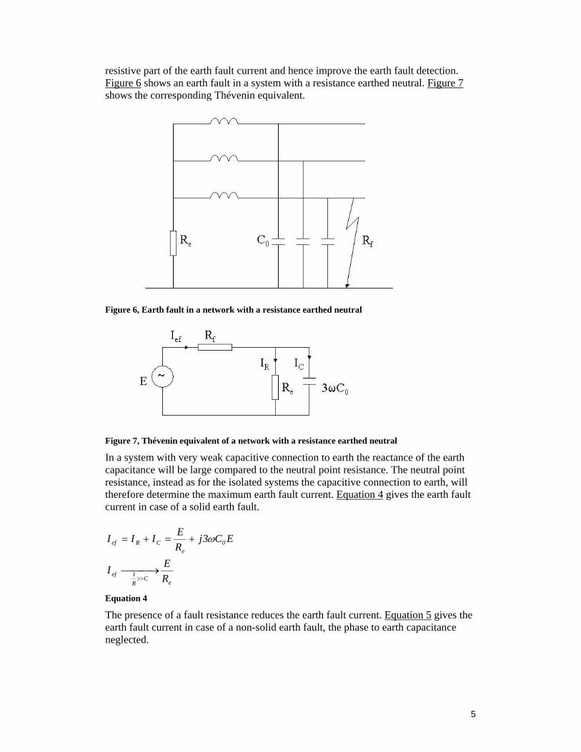
resistive part of the earth fault current and hence improve the earth fault detection. Figure 6 shows an earth fault in a system with a resistance earthed neutral. Figure 7 shows the corresponding Thévenin equivalent.
Figure 6, Earth fault in a network with a resistance earthed neutral
Figure 7, Thévenin equivalent of a network with a resistance earthed neutral
In a system with very weak capacitive connection to earth the reactance of the earth capacitance will be large compared to the neutral point resistance. The neutral point resistance, instead as for the isolated systems the capacitive connection to earth, will therefore determine the maximum earth fault current. Equation 4 gives the earth fault current in case of a solid earth fault.
eC
R1ef
0e
CRef
REI
EC3jREIII
⎯⎯ →⎯
+=+=
>>
ω
Equation 4
The presence of a fault resistance reduces the earth fault current. Equation 5 gives the earth fault current in case of a non-solid earth fault, the phase to earth capacitance neglected.

6
feef RR
EI+
=
Equation 5
As mention in previous section, systems with a very weak capacitive connection to earth are normally resistance earthed. To make the difference between fault currents of isolated and resistance earthed systems visible, earth fault current calculations have been carried out using Matlab. The resulting current as functions of fault resistance is shown in Figure 8. It is an obvious difference in earth fault current for fault resistances around 5 k ohm, while the difference in fault current for very high impedance faults, and hence unsymmetrical condition during normal operation, is small. If the systems capacitive earth fault current instead is 2 A there will hardly be any difference in earth fault current of isolated and resistance earthed systems for fault resistances above a couple of thousands ohm.
Figure 8, Fault current as function of fault resistance, for an isolated system Ic and resistance earthed system Ir
As in the case of a fault in an isolated system, the fault current gives rise to a neutral displacement voltage across the system’s impedance to earth. In the case of a resistance earthed system the impedance to earth is the neutral point resistance in parallel to the phase to earth capacitances. Equation 6 gives the neutral displacement voltage which in case of a solid earth fault equals the pre-fault phase to earth voltage of the faulted phase.

7
( )20
2
e
efn
C3R1
IU
ω+⎟⎟⎠
⎞⎜⎜⎝
⎛=
Equation 6
Advantages of high resistance earthed systems: • Enables high impedance fault detection in systems with weak capacitive
connection to earth • Some phase-to-earth faults is self-cleared. • The neutral point resistance can be chosen to limit the possible over voltage
transients to 2.5 times the fundamental frequency maximum voltage [1]. Transients are further discussed in section below.
Disadvantages: • Generates extensive earth fault currents when combined with strong or
moderate capacitive connection to earth. • Cost involved
Resonant earthed system To limit the reactive part of the earth fault current in a power system a neutral point reactor can be connected between the transformer neutral and the station earthing system. A system in which at least one of the neutrals is connected to earth via an inductive reactance, a Petersen coil, and the current generated by the reactance during an earth fault approximately compensates the capacitive component of the single phase earth fault current, is called a resonant earthed system. The system is hardly ever exactly tuned, i.e. the reactive current does not exactly equal the capacitive earth fault current of the system. A system in which the inductive current is slightly larger than the capacitive earth fault current is over compensated. A system in which the induced earth fault current is slightly smaller than the capacitive earth fault current is under compensated. Figure 9 shows the earth fault current phasors of a slightly over compensated system.
Figure 9, Earth fault current phasors of a slightly over compensated power system
The neutral point reactor is often combined with a neutral point resistor. In a resonant earthed system the resulting reactive part of the earth fault current is too small for the relay protection to measure. By using a neutral point resistance a measurable resistive earth fault current is created as explained in the section about resistance earthed systems. In addition to this, there will always be active losses in the neutral point generator, which contributes to the active part of the earth fault current. Typical examples of power systems with strong capacitive connection to earth, suitable for resonant earthing, are systems consisting of an extensive amount of cables. If the high capacitive earth fault current of such systems is not compensated, the risk of dangerously high potential rise of exposed parts of the power system is evident.
8
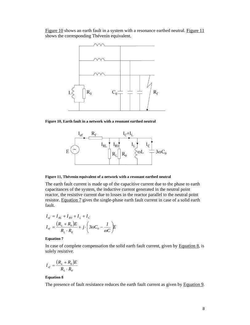
Figure 10 shows an earth fault in a system with a resonance earthed neutral. Figure 11 shows the corresponding Thévenin equivalent.
Figure 10, Earth fault in a network with a resonant earthed neutral
Figure 11, Thévenin equivalent of a network with a resonant earthed neutral
The earth fault current is made up of the capacitive current due to the phase to earth capacitances of the system, the inductive current generated in the neutral point reactor, the resistive current due to losses in the reactor parallel to the neutral point resistor. Equation 7 gives the single-phase earth fault current in case of a solid earth fault.
( )E
C1C3j
RRERR
I
IIIII
00L
0Lef
CL0RRLef
⎟⎠⎞
⎜⎝⎛ −⋅+
⋅+
=
+++=
ωω
Equation 7
In case of complete compensation the solid earth fault current, given by Equation 8, is solely resistive.
( )0L
0Lef RR
ERRI
⋅+
=
Equation 8
The presence of fault resistance reduces the earth fault current as given by Equation 9.

9
( )( ) ( )
L1C3X
RRRR
R
XR1RR
jXXR1RRRI
0e
0L
0Le
2ef
2ef
e2
efefeef
ωω −=
+=
++
+++=
Equation 9
In case of complete compensation the earth fault current is solely resistant as given by Equation 10.
( )0ffL0L
0Lef RRRRRR
ERRI
⋅+⋅+⋅+
=
Equation 10
Resonance earthing makes it possible to more or less eliminate the reactive earth fault current. The use of non-ideal neutral point reactors and transportation of reactive current does however cause resistive losses. The losses generate resistive earth fault currents, which cannot be compensated. For power systems with very high capacitive connection to earth and extensive reactive current transportation, these resistive earth fault currents may cause problem. One way to limit the resistive earth fault currents is to use distributed compensation. Chapter x which is a resume of an ELFORSK project carried out during the spring of 2006 further looks into when distributed compensation might be necessary and how it can be carried out. The resistive losses are hard to predict in such way analytical earth fault calculations is possible to carry out. Results from PSCAD simulations of simple power systems are presented in the ELFORSK resume chapter. Equation 11 gives the neutral displacement voltage, the voltage across the system’s impedance to earth. The maximum, solid earth fault, neutral point displacement voltage of a resonant earthed system equals the pre-fault phase to earth voltage. In case of high fault resistance the neutral point displacement voltage is higher than for corresponding fault resistance in an isolated system [Error! Reference source not found.].
2
0
2
e
ef0
L1C3
R1
IU
⎟⎠⎞
⎜⎝⎛ −+⎟⎟
⎠
⎞⎜⎜⎝
⎛=
ωω
Equation 11
Advantages of resonant earthed systems: • Small reactive earth fault current independent of the phase to earth capacitance
of the system. • Enables high impedance fault detection.
Disadvantages
• Risk of extensive active earth fault losses • Complicated relay protection

10
• High costs associated.
Effectively earthed systems A system in which the value of the phase to earth voltage of the healthy phases during an earth fault, never exceed 1.39 times the pre-fault phase to ground voltage is effectively earthed, see Equation 12. The relation between maximum voltage and pre- fault voltage is called the earth-fault factor. In practice most of the transformers neutral points are solidly earthed or earthed via very small impedances in an effectively earthed system [1]. In Equation 13, the earth fault factor in case of a solid earth fault is expressed in terms of symmetrical components. The coloured area in Figure 12 illustrates the relation between R0/X1 and X0/X1in an effectively earthed system.
39.1E
U hp ≤
Equation 12
( ) ( )( ) ( ) 39.1
1X2j1R21Xj1R
87.0j5.0E
U
0R,XXX
,RXR
,1XR
'0
'0
'0
'0hp
f'0
1
0'0
1
0
1
1
≤−⋅⋅+−⋅
−⋅+−−⋅±=
====
Equation 13
Figure 12, The coloured area illustrates the relation between R0/X1 (y-axis) and X0/X1 (x-axis), in an effectively earthed system

11
Other kinds of earthing There are other ways to label earthing methods. Impedance earthed systems includes all system earthed via an impedance, intended to limit the earth fault current [2]. The systems can be earthed via a resistance, resistance earthed system, a reactance, reactance earthed system, or a combination of these. In practice there are no such thing as an ideal reactor and strictly reactance earthed systems does therefore not exist in reality. Arc-suppression-coil earthing as well as Petersen earthed systems and systems with compensated neutrals are other names for the resonant earthed systems, the tuned impedance earthed systems explained above.
Comparison It is important to keep in mind that the earth fault current limitation counter acts the earth fault detection, no matter what earthing method is chosen. The earthing design shall limit the earth fault current and enable fault detection while keeping the associated costs as low as possible. The cost associated to the earthing of isolated systems is relatively low. When possible, power systems are therefore often isolated. It is not suitable isolate the neutral points of the systems if the system’s capacitive connection to earth is either very weak or quite strong. If the capacitive connection to earth is very weak neutral point resistors are connected to the system. If the capacitive connection to earth on the other hand is quite strong it is necessary to connect neutral point reactors, Petersen coils, to compensate for the capacitive earth fault current. One of the aims of this thesis is to further look into when it is suitable to use a certain earthing design. Since the Swedish distribution systems are of special interest in the PhD-project, extra attention will be given to the earthing methods suitable for Swedish conditions. The earth fault current of an isolated system is small as long as the networks capacitive connection to earth is limited. In the past, a majority of the circuits in Swedish medium voltage systems has been overhead lines, which have week capacitive connection to earth. The Swedish MV systems have therefore to a large extent been isolated. With the increased use of power cables, which has a strong capacitive connection to earth, resonant earthed systems are becoming increasingly popular in the Nordic countries [1] because today resonant earthing is the only earthing method that manages high capacitive earth fault currents.

12
References 1. Lehtonen, M. & Hakola, T.: ”Neutral earthing and power system protection”,
ISBN 952-90-7913-3, ABB Transmit Oy, Vaasa 1996 2. IEC multilingual dictionary, Sixth edition, 2005 3. Lindahl, S., Messing, L., Östlund, S., Olsson, B. & Petterson A.: ”Känsliga
jordfelsskydd. Bortkoppling av högresistiva jordslutningar i icke direkt jordade distributions- och transmissionssystem”, Svenska Elverksföreningen, Stockholm, 1990
4. Willheim, R. & Waters, M.: ”Neutral grounding in high voltage transmission”, Elsevier, New York, 1956