table of contents - nra · 7-3 chapter 7: interchanges ments, interchanges should provide ramps to...
TRANSCRIPT
TABLE OF CONTENTS
7. INTERCHANGES . . . . . . . . . . . . . . . . . . . . . . . . . . . . . . . . . . . . . . . . . . . . . . . . . . . . . . . . . . . . . 7-1
7.1 INTRODUCTION . . . . . . . . . . . . . . . . . . . . . . . . . . . . . . . . . . . . . . . . . . . . . . . . . . . . . . 7-1
7.1.1 General. . . . . . . . . . . . . . . . . . . . . . . . . . . . . . . . . . . . . . . . . . . . . . . . . . . . . . . . . 7-1
7.1.2 Design principles. . . . . . . . . . . . . . . . . . . . . . . . . . . . . . . . . . . . . . . . . . . . . . . . . . 7-1
7.2 INTERCHANGE WARRANTS . . . . . . . . . . . . . . . . . . . . . . . . . . . . . . . . . . . . . . . . . . . . . 7-3
7.2.1 Traffic volumes . . . . . . . . . . . . . . . . . . . . . . . . . . . . . . . . . . . . . . . . . . . . . . . . . . . 7-3
7.2.2 Freeways . . . . . . . . . . . . . . . . . . . . . . . . . . . . . . . . . . . . . . . . . . . . . . . . . . . . . . . 7-4
7.2.3 Safety . . . . . . . . . . . . . . . . . . . . . . . . . . . . . . . . . . . . . . . . . . . . . . . . . . . . . . . . . . 7-4
7.2.4 Topography. . . . . . . . . . . . . . . . . . . . . . . . . . . . . . . . . . . . . . . . . . . . . . . . . . . . . . 7-4
7.3 WEAVING. . . . . . . . . . . . . . . . . . . . . . . . . . . . . . . . . . . . . . . . . . . . . . . . . . . . . . . . . . . . 7-4
7.4 LOCATION AND SPACING OF INTERCHANGES. . . . . . . . . . . . . . . . . . . . . . . . . . . . . . 7-6
7.5 BASIC LANES AND LANE BALANCE. . . . . . . . . . . . . . . . . . . . . . . . . . . . . . . . . . . . . . . 7-9
7.6 AUXILIARY LANES . . . . . . . . . . . . . . . . . . . . . . . . . . . . . . . . . . . . . . . . . . . . . . . . . . . 7-10
7.6.1 The need for an auxiliary lane . . . . . . . . . . . . . . . . . . . . . . . . . . . . . . . . . . . . . . . 7-10
7.6.2 Auxiliary lane terminals . . . . . . . . . . . . . . . . . . . . . . . . . . . . . . . . . . . . . . . . . . . . 7-13
7.6.3 Driver information . . . . . . . . . . . . . . . . . . . . . . . . . . . . . . . . . . . . . . . . . . . . . . . . 7-13
7.7 INTERCHANGE TYPES . . . . . . . . . . . . . . . . . . . . . . . . . . . . . . . . . . . . . . . . . . . . . . . . 7-13
7.7.1 General. . . . . . . . . . . . . . . . . . . . . . . . . . . . . . . . . . . . . . . . . . . . . . . . . . . . . . . . 7-13
7.7.2 Systems interchanges. . . . . . . . . . . . . . . . . . . . . . . . . . . . . . . . . . . . . . . . . . . . . 7-15
7.7.3 Access and service interchanges . . . . . . . . . . . . . . . . . . . . . . . . . . . . . . . . . . . . 7-17
7.7.4 Interchanges on non-freeway roads. . . . . . . . . . . . . . . . . . . . . . . . . . . . . . . . . . . 7-23
7.8 RAMP DESIGN. . . . . . . . . . . . . . . . . . . . . . . . . . . . . . . . . . . . . . . . . . . . . . . . . . . . . . . 7-23
7.8.1 General. . . . . . . . . . . . . . . . . . . . . . . . . . . . . . . . . . . . . . . . . . . . . . . . . . . . . . . . 7-23
7.8.2 Design speed . . . . . . . . . . . . . . . . . . . . . . . . . . . . . . . . . . . . . . . . . . . . . . . . . . . 7-24
7.8.3 Sight distance on ramps . . . . . . . . . . . . . . . . . . . . . . . . . . . . . . . . . . . . . . . . . . . 7-25
7.8.4 Horizontal alignment . . . . . . . . . . . . . . . . . . . . . . . . . . . . . . . . . . . . . . . . . . . . . . 7-26
7.8.5 Vertical alignment . . . . . . . . . . . . . . . . . . . . . . . . . . . . . . . . . . . . . . . . . . . . . . . . 7-27
7.8.6 Cross-section . . . . . . . . . . . . . . . . . . . . . . . . . . . . . . . . . . . . . . . . . . . . . . . . . . . 7-28
7.8.7 Terminals . . . . . . . . . . . . . . . . . . . . . . . . . . . . . . . . . . . . . . . . . . . . . . . . . . . . . . 7-29
7.9 COLLECTOR - DISTRIBUTOR ROADS . . . . . . . . . . . . . . . . . . . . . . . . . . . . . . . . . . . . 7-35
7.10 OTHER INTERCHANGE DESIGN FEATURES . . . . . . . . . . . . . . . . . . . . . . . . . . . . . . . 7-35
7.10.1Ramp metering . . . . . . . . . . . . . . . . . . . . . . . . . . . . . . . . . . . . . . . . . . . . . . . . . . 7-35
7.10.2Express-collector systems. . . . . . . . . . . . . . . . . . . . . . . . . . . . . . . . . . . . . . . . . . 7-36

LIST OF TABLES
Table 7.1: Interchange spacing in terms of signage requirements . . . . . . . . . . . . . . . . . . . . . . . . . . . . . . . . 7-7Table 7.2: Ramp design speed . . . . . . . . . . . . . . . . . . . . . . . . . . . . . . . . . . . . . . . . . . . . . . . . . . . . . . . . . 7-24Table 7.3: Maximum resultant gradients. . . . . . . . . . . . . . . . . . . . . . . . . . . . . . . . . . . . . . . . . . . . . . . . . . . 7-27Table 7.4: K-Values of crest curvature for decision sight distance. . . . . . . . . . . . . . . . . . . . . . . . . . . . . . . . 7-28Table 7.5: Length of deceleration lanes (m) . . . . . . . . . . . . . . . . . . . . . . . . . . . . . . . . . . . . . . . . . . . . . . . . 7-31Table 7.6: Length of acceleration lanes (m) . . . . . . . . . . . . . . . . . . . . . . . . . . . . . . . . . . . . . . . . . . . . . . . . 7-31Table 7.7: Taper rates for exit ramps . . . . . . . . . . . . . . . . . . . . . . . . . . . . . . . . . . . . . . . . . . . . . . . . . . . . . 7-32
LIST OF FIGURES
Figure 7.1: Type A weaves: (a) ramp-weave . . . . . . . . . . . . . . . . . . . . . . . . . . . . . . . . . . . . . . . . . . . . . . . . 7-5. . (b) major weave with crown line . . . . . . . . . . . . . . . . . . . . . . . . . . . . . . . . . . . . . . . . . . . . . . . . 7-5
Figure 7.2: Type B weaves: (a) major weave with lane balance at exit . . . . . . . . . . . . . . . . . . . . . . . . . . . . . 7-5. . (b) major weave with merging at entrance. . . . . . . . . . . . . . . . . . . . . . . . . . . . . . . . . . . . . . . . . 7-5. . (c) major weave with merging at entrance and lane balance at exit . . . . . . . . . . . . . . . . . . . . . . 7-5
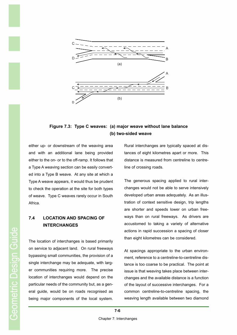
Figure 7.3: Type C weaves: (a) major weave without lane balance . . . . . . . . . . . . . . . . . . . . . . . . . . . . . . . 7-6. . (b) two-sided weave . . . . . . . . . . . . . . . . . . . . . . . . . . . . . . . . . . . . . . . . . . . . . . . . . . . . . . . . . 7-6
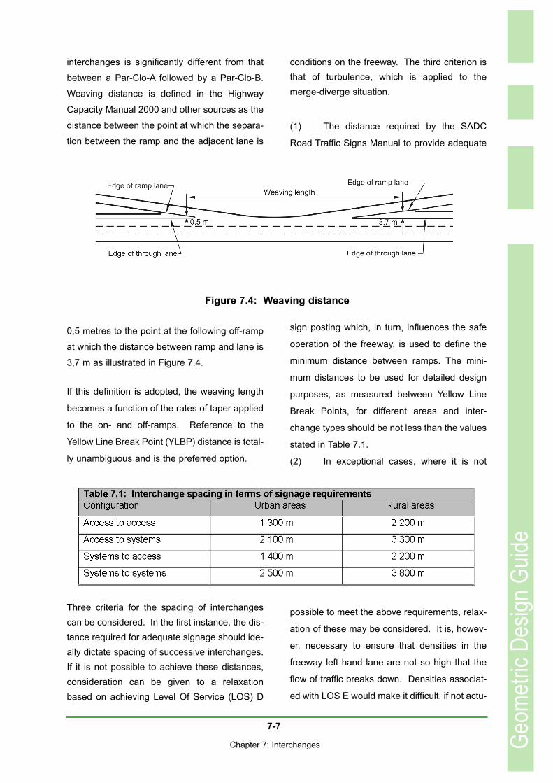
Figure 7.4: Weaving distance . . . . . . . . . . . . . . . . . . . . . . . . . . . . . . . . . . . . . . . . . . . . . . . . . . . . . . . . . . . 7-7Figure 7.5: Relationship between interchange spacing and accident rate. . . . . . . . . . . . . . . . . . . . . . . . . . . 7-9Figure 7.6: Coordination of lane balance with basic number of lanes . . . . . . . . . . . . . . . . . . . . . . . . . . . . . 7-11Figure 7.7: Four-legged systems interchanges . . . . . . . . . . . . . . . . . . . . . . . . . . . . . . . . . . . . . . . . . . . . . 7-16Figure 7.8: Three-legged systems interchanges . . . . . . . . . . . . . . . . . . . . . . . . . . . . . . . . . . . . . . . . . . . . 7-17Figure 7.9: Diamond interchanges. . . . . . . . . . . . . . . . . . . . . . . . . . . . . . . . . . . . . . . . . . . . . . . . . . . . . . . 7-20Figure 7.10: Par-Clo A interchanges . . . . . . . . . . . . . . . . . . . . . . . . . . . . . . . . . . . . . . . . . . . . . . . . . . . . . 7-21Figure 7.11: Par-Clo B interchanges . . . . . . . . . . . . . . . . . . . . . . . . . . . . . . . . . . . . . . . . . . . . . . . . . . . . . 7-22Figure 7.12: Par-Clo AB interchanges and rotaries . . . . . . . . . . . . . . . . . . . . . . . . . . . . . . . . . . . . . . . . . . 7-22Figure 7.13: Jug Handle interchange. . . . . . . . . . . . . . . . . . . . . . . . . . . . . . . . . . . . . . . . . . . . . . . . . . . . . 7-23Figure 7.14: Single lane exit . . . . . . . . . . . . . . . . . . . . . . . . . . . . . . . . . . . . . . . . . . . . . . . . . . . . . . . . . . . 7-32Figure 7.15: Two-lane exit . . . . . . . . . . . . . . . . . . . . . . . . . . . . . . . . . . . . . . . . . . . . . . . . . . . . . . . . . . . . . 7-32Figure 7.16: One lane entrance. . . . . . . . . . . . . . . . . . . . . . . . . . . . . . . . . . . . . . . . . . . . . . . . . . . . . . . . . 7-33Figure 7:17: Two-lane entrance. . . . . . . . . . . . . . . . . . . . . . . . . . . . . . . . . . . . . . . . . . . . . . . . . . . . . . . . . 7-33Figure 7.18: Major fork . . . . . . . . . . . . . . . . . . . . . . . . . . . . . . . . . . . . . . . . . . . . . . . . . . . . . . . . . . . . . . . 7-34
7-1
Chapter 7: Interchanges
Chapter 7INTERCHANGES
7.1 INTRODUCTION
7.1.1 General
The principal difference between interchanges
and other forms of intersection is that, in inter-
changes, crossing movements are separated in
space whereas, in the latter case,they are sep-
arated in time. At-grade intersections accom-
modate turning movements either within the lim-
itations of the crossing roadway widths or
through the application of turning roadways
whereas the turning movements at interchanges
are accommodated on ramps. The ramps
replace the slow turn through an angle of skew
that is approximately equal to 90O by high-speed
merging and diverging manoeuvres at relatively
flat angles.
Grade separations, discussed further in Chapter
10, provide spatial separation between the
crossing movements but do not make provision
for turning movements. They, therefore, do not
qualify for consideration as a form of intersec-
tion.
The first interchange ever built was at
Woodbridge, New Jersey, and provided (in the
context of driving on the right) loops for all left
turns and outer connectors for all right turns
thus creating the Cloverleaf Interchange. Since
then, a variety of interchange forms has been
developed. These include the:
• Diamond;
• Par-Clo (from Partial Cloverleaf); and the
• Directional
The various types of interchange configuration
are illustrated in Section 7.6. Each basic form
can be divided into sub-types. For example, the
Diamond Interchange is represented by the nar-
row diamond, the wide diamond and the split
diamond. The most recent development in the
Diamond interchange form is the Single Point
Diamond Interchange. This form is also referred
to as the Urban Interchange.
Historically, the type of interchange to be
applied at a particular site would be selected as
an input into the design process. In fact, like the
cross-section, the interchange is the aggrega-
tion of various elements. A more sensible
approach is thus to select the elements appro-
priate to a particular site in terms of the topog-
raphy, local land usage and traffic move-
ments and then to aggregate them into some or
other type of interchange.
7.1.2 Design principles
Manoeuvres in an interchange area occur at
high speeds close to the freeway and over rela-
tively short distances. It is therefore important
that drivers should experience no difficulty in
recognising their route through the interchange
irrespective of whether that route traverses the
interchange on the freeway or diverts to depart
from the freeway to a destination that may be to
the left or the right of the freeway. In following
their selected route, drivers should be disturbed
as little as possible by other traffic. These
requirements can be met through the applica-
Geom
etric
Desig
n Gu
ide

7-2
Chapter 7: Interchanges
tion of the basic principles of interchange
design.
The driver has a number of tasks to execute
successfully to avoid being a hazard to other
traffic. It is necessary to:• select a suitable speed and accelerate
or decelerate to the selected speed within the available distance;
• select the appropriate lane and carry outthe necessary weaving manoeuvres to effect lane changes if necessary; and
• diverge towards an off-ramp or merge from an on-ramp with the through traffic.
To maintain safety in carrying out these tasks,
the driver must be able to understand the oper-
ation of the interchange and should not be sur-
prised or misled by an unusual design charac-
teristic. Understanding is best promoted by con-
sistency and uniformity in the selection of types
and in the design of particular features of the
interchange.
Interchange exits and entrances should always
be located on the left. Right-hand side
entrances and exits are counter to driver
expectancy and also have the effect of mixing
high-speed through traffic with lower-speed
turning vehicles. The problem of extracting turn-
ing vehicles from the median island and provid-
ing sufficient vertical clearance either over or
under the opposing freeway through lanes is not
trivial. The application of right-hand entrances
and exits should only be considered under
extremely limiting circumstances. Even in the
case of a major fork where two freeways are
diverging, the lesser movement should, for pref-
erence, be on the left.
Route continuity substantially simplifies the nav-
igational aspects of the driving task. For exam-
ple, if a driver simply wishes to travel on a free-
way network through a city from one end to the
other it should not be necessary to deviate from
one route to another.
Uniformity of signing practice is an important
aspect of consistent design and reference
should be made to the SADC Road Traffic Signs
Manual.
Ideally, an interchange should have only a sin-
gle exit for each direction of flow with this being
located in advance of the interchange structure.
The directing of traffic to alternative destinations
on either side of the freeway should take place
clear of the freeway itself. In this manner, driv-
ers will be required to take two binary decisions,
(Yes/No) followed by (Left/Right), as opposed to
a single compound decision. This spreads the
workload and simplifies the decision process,
hence improving the operational efficiency of
the entire facility. Closely spaced successive
off-ramps could be a source of confusion to the
driver leading to erratic responses and manoeu-
vres.
Single entrances are to be preferred, also in
support of operational efficiency of the inter-
change. Merging manoeuvres by entering vehi-
cles are an interruption of the free flow of traffic
in the left lane of the freeway. Closely spaced
entrances exacerbate the problem and the
resulting turbulence could influence the adja-
cent lanes as well.
From the standpoint of convenience and safety,
in particular prevention of wrong-way move-
Geom
etric
Desig
n Gu
ide
7-3
Chapter 7: Interchanges
ments, interchanges should provide ramps to
serve all turning movements. If, for any reason,
this is not possible or desirable, it is neverthe-
less to be preferred that, for any travel move-
ment from one road to another within an inter-
change, the return movement should also be
provided.
Provision of a spatial separation between two
crossing streams of traffic raises the problem of
which to take over the top - the perennial Over
versus Under debate. The choice of whether
the crossing road should be taken over or under
the freeway depends on a number of factors,
not the least of which is the matter of terrain and
construction costs. There are, however, a num-
ber of advantages in carrying the crossing road
over the freeway. These are:
• Exit ramps on up-grades assist deceler-
ation and entrance ramps on down-
grades assist acceleration and have a
beneficial effect on truck noise.
• Rising exit ramps are highly visible to
drivers who may wish to exit from the
freeway.
• The structure has target value, i.e. it
provides advance warning of the possi-
bility of an interchange ahead necessi-
tating a decision from the driver whether
to stay on the freeway or perhaps to
change lanes with a view to the impend-
ing departure from the freeway.
• Dropping the freeway into cut reduces
noise levels to surrounding communi-
ties and also reduces visual intrusion.
• For the long-distance driver on a rural
freeway, a crossing road on a structure
may represent an interesting change of
view.
• The crossing road ramp terminals may
include right and left turn lanes, traffic
signals and other traffic control devices.
Not being obstructed by bridge piers
and the like, these would be rendered
more visible by taking the crossing road
over the freeway.
The other design principles, being continuity of
basic lanes, lane balance and lane drops are
discussed in Section 7.5 as matters of detailed
design.
7.2 INTERCHANGE WARRANTS
7.2.1 Traffic volumes
With increasing traffic volumes, a point will be
reached where all the options of temporal sepa-
ration of conflicting movements at an at-grade
intersection have been exhausted. One of the
possible solutions to the problem is to provide
an interchange.
The elimination of bottlenecks by means of
interchanges can be applied to any intersection
at which demand exceeds capacity and is not
necessarily limited to arterials. Under these cir-
cumstances, it is necessary to weigh up the
economic benefits of increased safety, reduced
delay and reduced operating and maintenance
cost of vehicles against the cost of provision of
the interchange. The latter includes the cost of
land acquisition, which could be high, and the
cost of construction. As the construction site
would be heavily constricted by the need to
accommodate traffic flows that were sufficiently
heavy to justify the interchange in the first
instance, the cost of construction could be sig-
nificantly higher than on the equivalent green
field site.
Geom
etric
Desig
n Gu
ide

7-4
Chapter 7: Interchanges
7.2.2 Freeways
The outstanding feature of freeways is the limi-
tation of access that is brought to bear on their
operation. Access is permitted only at designat-
ed points and only to vehicles travelling at or
near freeway speeds. As such, access by
means of intersections is precluded and the only
permitted access is by way of interchanges.
Crossing roads are normally those that are high
in the functional road hierarchy, e.g. arterials,
although, if these are very widely spaced, it may
be necessary to provide an interchange serving
a lower order road, for example a collector.
It follows that the connection between two free-
ways would also be by means of an inter-
change, in which case reference is to a systems
interchange as opposed to an access inter-
change.
7.2.3 Safety
Some at-grade intersections exhibit high crash
rates that cannot be lowered by improvements
to the geometry of the intersections or through
the application of control devices. Such situa-
tions are often found at heavily travelled urban
intersections. Crash rates also tend to be high
at the intersections on heavily travelled rural
arterials where there is a proliferation of ribbon
development.
A third area of high crash rates is at intersec-
tions on lightly travelled low volume rural loca-
tions where speeds tend to be high. In these
cases, low-cost interchanges such as the Jug-
handle layout may be an adequate solution to
the problem.
7.2.4 Topography
The topography may force a vertical separation
between crossing roads at the logical intersec-
tion location. As an illustration, the through road
may be on a crest curve in cut with the crossing
road at or above ground level. If it is not possi-
ble to relocate the intersection, a simple Jug-
handle type of interchange as illustrated in
Figure 7.13 may be an adequate solution to the
problem.
7.3 WEAVING
The Highway Capacity Manual (2000) defines
weaving as the crossing of two or more traffic
streams travelling in the same general direction
without the aid of traffic control devices but then
goes to address the merge-diverge as a sepa-
rate issue. However, the merge-diverge opera-
tion, associated with successive single-lane on-
and off-ramps where there is no auxiliary lane,
does have two streams that, in fact, are cross-
ing. Reference to weaving should thus include
the merge-diverge.
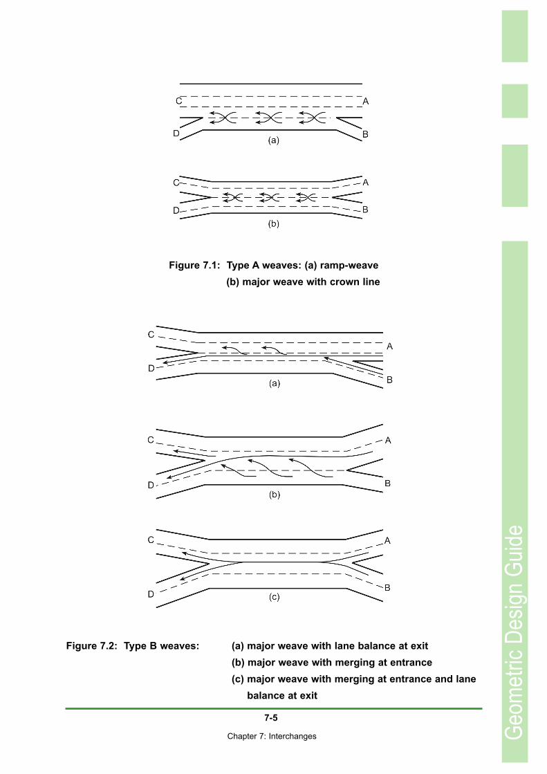
Three types of weave are illustrated in Figures
7.1, 7.2 and 7.3. A Type A weave requires all
weaving vehicles to execute one lane change.
Type B weaving occurs when one of the weav-
ing streams does not have to change lanes but
the other has to undertake at most one lane
change. Type C weaving allows one stream to
weave without making a lane change, whereas
the other stream has to undertake two or more
lane changes.
The Type B weave is, in essence, a Type A
weave but with the auxiliary lane extending
Geom
etric
Desig
n Gu
ide
7-5
Chapter 7: Interchanges Geom
etric
Desig
n Gu
ide
Figure 7.2: Type B weaves: (a) major weave with lane balance at exit (b) major weave with merging at entrance (c) major weave with merging at entrance and lane
balance at exit
Figure 7.1: Type A weaves: (a) ramp-weave (b) major weave with crown line
7-6
Chapter 7: Interchanges
either up- or downstream of the weaving area
and with an additional lane being provided
either to the on- or to the off-ramp. It follows that
a Type A weaving section can be easily convert-
ed into a Type B weave. At any site at which a
Type A weave appears, it would thus be prudent
to check the operation at the site for both types
of weave. Type C weaves rarely occur in South
Africa.
7.4 LOCATION AND SPACING OF INTERCHANGES
The location of interchanges is based primarily
on service to adjacent land. On rural freeways
bypassing small communities, the provision of a
single interchange may be adequate, with larg-
er communities requiring more. The precise
location of interchanges would depend on the
particular needs of the community but, as a gen-
eral guide, would be on roads recognised as
being major components of the local system.
Rural interchanges are typically spaced at dis-
tances of eight kilometres apart or more. This
distance is measured from centreline to centre-
line of crossing roads.
The generous spacing applied to rural inter-
changes would not be able to serve intensively
developed urban areas adequately. As an illus-
tration of context sensitive design, trip lengths
are shorter and speeds lower on urban free-
ways than on rural freeways. As drivers are
accustomed to taking a variety of alternative
actions in rapid succession a spacing of closer
than eight kilometres can be considered.
At spacings appropriate to the urban environ-
ment, reference to a centreline-to-centreline dis-
tance is too coarse to be practical. The point at
issue is that weaving takes place between inter-
changes and the available distance is a function
of the layout of successive interchanges. For a
common centreline-to-centreline spacing, the
weaving length available between two diamond
Geom
etric
Desig
n Gu
ide
Figure 7.3: Type C weaves: (a) major weave without lane balance (b) two-sided weave
7-7
Chapter 7: Interchanges
interchanges is significantly different from that
between a Par-Clo-A followed by a Par-Clo-B.
Weaving distance is defined in the Highway
Capacity Manual 2000 and other sources as the
distance between the point at which the separa-
tion between the ramp and the adjacent lane is
0,5 metres to the point at the following off-ramp
at which the distance between ramp and lane is
3,7 m as illustrated in Figure 7.4.
If this definition is adopted, the weaving length
becomes a function of the rates of taper applied
to the on- and off-ramps. Reference to the
Yellow Line Break Point (YLBP) distance is total-
ly unambiguous and is the preferred option.
Three criteria for the spacing of interchangescan be considered. In the first instance, the dis-tance required for adequate signage should ide-ally dictate spacing of successive interchanges.If it is not possible to achieve these distances,consideration can be given to a relaxationbased on achieving Level Of Service (LOS) D
conditions on the freeway. The third criterion isthat of turbulence, which is applied to themerge-diverge situation.
(1) The distance required by the SADC
Road Traffic Signs Manual to provide adequate
sign posting which, in turn, influences the safe
operation of the freeway, is used to define the
minimum distance between ramps. The mini-
mum distances to be used for detailed design
purposes, as measured between Yellow Line
Break Points, for different areas and inter-
change types should be not less than the values
stated in Table 7.1.
(2) In exceptional cases, where it is not
possible to meet the above requirements, relax-
ation of these may be considered. It is, howev-
er, necessary to ensure that densities in the
freeway left hand lane are not so high that the
flow of traffic breaks down. Densities associat-
ed with LOS E would make it difficult, if not actu-
Geom
etric
Desig
n Gu
ide
Figure 7.4: Weaving distance

7-8
Chapter 7: Interchanges
ally impossible, for drivers to be able to change
lanes. Formulae according to which densities
can be estimated are provided in the Highway
Capacity Manual (2000). Drivers need time to
locate a gap and then to position themselves
correctly in relation to the gap while simultane-
ously adjusting their speed to that required for
the lane change. The actual process of chang-
ing lanes also requires time.
(3) In the case of the merge-diverge
manoeuvre, turbulence caused on the left lane
of the freeway by a close succession of entering
and exiting vehicles becomes an issue.
According to Roess and Ulerio this turbulence
manifests itself over a distance of roughly 450
metres upstream of an off-ramp and down-
stream of an on-ramp. A spacing of 900 metres
would suggest that the entire length of freeway
between interchanges would be subject to tur-
bulent flow. The likelihood of breakdown in the
traffic flow would thus be high and the designer
should ensure that space is available for one
area of turbulence to subside before onset of
the next.
(4) In off-peak periods, vehicles would be
moving between interchanges at the design
speed or higher. The geometry of the on- and
off-ramps should be such that they can accom-
modate manoeuvres at these speeds.
Increasing the taper rates or reducing the length
of the speed change lanes purely to achieve
some or other hypothetically acceptable Yellow
Line Break Point distance does not constitute
good design.
(5) The spacing between successive inter-
changes will have an impact on traffic opera-
tions on the crossing roads and vice versa. If
the crossing road can deliver vehicles to the
freeway faster than they can carry out the
merge, stacking of vehicles will occur on the on-
ramp with the queue possibly backing up on to
the crossing road itself. Stacking can also occur
on an off-ramp if the crossing road ramp termi-
nal cannot accommodate the rate of flow arriv-
ing from the freeway. The queue could conceiv-
ably back up onto the freeway, which would cre-
ate an extremely hazardous situation.
It should be realised that relaxations below the
distances recommended under (1) above will
result in an increase in the driver workload.
Failure to accommodate acceptable levels of
driver workload in relation to reaction times can
be expected to result in higher than average
crash rates. Twomey et al demonstrate that, at
spacings between noses of greater than 2 500
metres, the crash rate is fairly constant, i.e. the
presence of the following interchange is not a
factor in the crash rate. At spacings of less than
2500 m between noses, the crash rate increas-
es until, at about 500 m between noses, the
crash rate is nearly double that of the 2500 m
spacing. This is illustrated in Figure 7.2 below
The question that must be addressed is the ben-
efit that the community can expect to derive in
exchange for the cost of the higher accident
rate. By virtue of the fact that freeway speeds
tend to be high, there is a high probability that
many of the accidents would be fatal. It is there-
fore suggested that the decision to reduce the
interchange spacing below those listed in Table
7.1 should not be taken lightly.
It would be necessary to undertake a full-scale
engineering analysis of the situation that would
include:• estimation of future traffic volumes at a
Geom
etric
Desig
n Gu
ide

7-9
Chapter 7: Interchanges
ten to twenty year time horizon, com-prising weaving and through volumes inthe design year;
• calculation of traffic densities;
assessment of the local geometry in
terms of sight distances, and horizontal
and vertical alignment; • development of a sign sequence; and• a form of benefit/cost analysis relating
community benefits to the decrease in traffic safety.
Density offers some indication of the level of
exposure to risk and, for want of any better
measure, it is suggested that a density higher
than 22 vehicles/kilometre/lane, corresponding
to LOS D, would not result in acceptable design.
It would be necessary to pay attention to reme-
dial actions to prevent interchange constraints,
such as inadequate ramp capacity, signalling or
crossroad volumes, causing back up onto the
freeway
In summary: Spacings of interchanges in terms
of their YLBP distances should desirably be in
accordance with Table 7.1. If these spacings
are not achievable and an interchange is
absolutely vital for service to the community and
adjacent land uses, relaxations may be consid-
ered but then, to minimise the risk of crashes,
the density calculated according to the above-
mentioned formulae should not exceed 22 vehi-
cles/kilometre/lane, which corresponds to LOS D.
7.5 BASIC LANES AND LANE BALANCE
Basic lanes are those that are maintained over
an extended length of a route, irrespective of
local changes in traffic volumes and require-
ments for lane balance. Alternatively stated, the
basic number of lanes is a constant number of
lanes assigned to a route, exclusive of auxiliary
lanes.
The number of basic lanes changes only when
there is a significant change in the general level
of traffic volumes on the route. Short sections of
the route may thus have insufficient capacity,
which problem can be overcome by the use of
auxiliary lanes. In the case of spare capacity,
reduction in the number of lanes is not recom-
Geom
etric
Desig
n Gu
ide
Figure 7.5: Relationship between interchange spacing and accident rate
•

7-10
Chapter 7: Interchanges
mended because this area could, at some future
time, become a bottleneck. Unusual traffic
demands, created by accidents, maintenance or
special events, could also result in these areas
becoming bottlenecks.
The basic number of lanes is derived from con-
sideration of the design traffic volumes and
capacity analyses. To promote the smooth flow
of traffic there should be a proper balance of
lanes at points where merging or diverging
manoeuvres occur. In essence, there should be
one lane where the driver has the choice of a
change of direction without the need to change
lanes.
At merges, the number of lanes downstream of
the merge should be one less than the number
of lanes upstream of the merge. This is typified
by a one-lane ramp merging with a two-lane car-
riageway that, after the merge, continues as a
two-lane carriageway as is the case on a typical
Diamond Interchange layout. This rule pre-
cludes a two-lane ramp immediately merging
with the carriageway without the addition of an
auxiliary lane.
At diverges, the number of lanes downstream of
the diverge should be one more than the num-
ber upstream of the diverge. The only exception
to this rule is on short weaving sections, such as
at Cloverleaf Interchanges, where a condition of
this exception is that there is an auxiliary lane
through the weaving section.
When two lanes diverge from the freeway, the
above rule indicates that the number of freeway
lanes beyond the diverge is reduced by one.
This can be used to drop a basic lane to match
anticipated flows beyond the diverge.
Alternatively, it can be an auxiliary lane that is
dropped.
Basic lanes and lane balance are brought into
harmony with each other by building on the
basic lanes, adding or removing auxiliary lanes
as required. The principle of lane balance
should always be applied in the use of auxiliary
lanes. Operational problems on existing road-
ways can be directly attributed to a lack of lane
balance and failure to maintain route continuity.
The application of lane balance and coordina-
tion with basic number of lanes is illustrated in
Figure 7.6
7.6 AUXILIARY LANES
As in the case of the two-lane two-way road
cross-section with its climbing and passing
lanes, and the intersection with its right- and left-
turning lanes, the auxiliary lane also has its role
to play in the freeway cross-section and the
interchange. In a sense, the application of the
auxiliary lane in the freeway environment is
identical to its application elsewhere. It is added
to address a local operational issue and, as
soon as the need for the auxiliary lane is past, it
is dropped.
Important features to consider in the application
and design of the auxiliary lane are thus:• The need for an auxiliary lane;• The terminals;• Driver information
7.6.1 The need for an auxiliary lane
Auxiliary lanes are normally required on free-
Geom
etric
Desig
n Gu
ide

7-11
Chapter 7: Interchanges
ways either as:• climbing lanes; or• to support weaving; or• to support lane balance.
The climbing lane application is similar to that
discussed in Chapter 4 in respect of two-lane
two-way roads whereas the weaving and lane
balance applications are unique to the freeway
situation.
Climbing lanes
Ideally, maximum gradients on freeways are in
the range of three to four per cent ensuring that
most vehicles can maintain a high and fairly
constant speed. However, in heavily rolling
country it is not always possible to achieve this
ideal without incurring excessive costs in terms
of earthworks construction. Because of the
heavy volumes of traffic that necessitate the
provision of a freeway, lane changing to over-
take a slow-moving vehicle is not always easy
and, under peak flow conditions, may actually
Geom
etric
Desig
n Gu
ideFigure 7.6: Coordination of lane balance with basic number of lanes

7-12
Chapter 7: Interchanges
be impossible. Speed differentials in the traffic
stream are thus not only extremely disruptive
but may also be potentially dangerous. Both
conditions, i.e. disruption and reduction in safe-
ty, require consideration.
If a gradient on a freeway is steeper than four
per cent, an operational analysis should be car-
ried out to establish the impact of the gradient
on the Level of Service. A drop through one
level, e.g from LOS B through LOS C to LOS D,
would normally suggest a need for a climbing
lane.
As discussed in Chapter 4, crash rates increase
exponentially with increasing speed differential.
For this reason, international warrants for climb-
ing lanes normally include a speed differential in
the range of 15 to 20 km/h. South Africa has
adopted a truck speed reduction of 20 km/h as
its speed-based warrant for climbing lanes. If,
on an existing freeway, the measured truck
speed reduction in the outermost lane is thus 20
km/h or higher, the provision of a climbing lane
should be considered. In the case of a new
design, it will be necessary to construct a speed
profile of the truck traffic to evaluate the need for
a climbing lane.
Weaving
In the urban environment, interchanges are fair-
ly closely spaced and local drivers are very
inclined to use freeways as part of the local cir-
culation system - a form of rat-running in
reverse and as undesirable as the normal form
of rat-running where the higher order road is
bypassed through the use of local residential
streets as long-distance urban routes. To
ensure that the freeway is not unduly congested
because of this practice, an auxiliary lane can
be provided between adjacent interchanges
resulting in Type A weaving as described in
Section 7.3.
If a large number of vehicles are entering at the
upstream interchange, it may be necessary to
provide a two-lane entrance ramp. Some of
these vehicles may exit at the following inter-
change but those wishing to travel further will
have to weave across traffic from still further
upstream that intends exiting at the following
interchange and then merge with through traffic
on the freeway. The auxiliary lane is then
extended beyond the downstream interchange
to allow a separation between the two manoeu-
vres. Similarly, a large volume of exiting vehi-
cles may necessitate a two-lane exit, in which
case the auxiliary lane should be extended
upstream. Type B weaving thus comes into
being. The desired length of the extension of
the auxiliary lane beyond the two interchanges
is normally assessed in terms of the probability
of merging vehicles locating an acceptable gap
in the opposing traffic flow.
Lane balance
As discussed in Section 7.5, lane balance
requires that:• In the case of an exit, the number of
lanes downstream of the diverge shouldbe one more than the number upstream;and
• In the case of an entrance, the number of lanes downstream of the merge should be one less than the number upstream
Geom
etric
Desig
n Gu
ide
7-13
Chapter 7: Interchanges
This is illustrated in Figure 7.6.
Single-lane on- and off-ramps do not require
auxiliary lanes to achieve lane balance in terms
of the above definition. It should be noted that,
unless two-lane on- and off-ramps are provided,
the Type A weave is actually a violation of the
principles of lane balance.
To achieve lane balance at an exit, three lanes
upstream of the diverge should be followed by a
two-lane off-ramp in combination with two basic
lanes on the freeway. The continuity of basic
lanes requires that the outermost of the three
upstream lanes should be an auxiliary lane.
If all three upstream lanes are basic lanes, it is
possible that traffic volumes beyond the off-
ramp may have reduced to the point where
three basic lanes are no longer necessary.
Provision of a two-lane exit would thus be a
convenient device to achieve a lane drop while
simultaneously maintaining lane balance. The
alternative would be to provide a single-lane off-
ramp, carrying the basic lanes through the inter-
change and dropping the outside lane some dis-
tance beyond the on-ramp terminal. In view of
the additional construction costs involved, this
approach is not recommended.
If a two-lane on-ramp is joining two basic lanes,
lane balance will require that there be three
lanes beyond the merge. The outside lane of
the three could become a new basic lane if the
increase in traffic on the freeway merits it. On
the other hand, it is possible that the flow on the
ramp is essentially a local point of high density
and that two basic lanes are all that are required
downstream of the on-ramp. In this case, the
outside lane could be dropped as soon as con-
venient.
7.6.2 Auxiliary lane terminals
An auxiliary lane is intended to match a particu-
lar situation such as, for example, an unaccept-
ably high speed differential in the traffic stream.
It follows that the full width of auxiliary lane must
be provided over the entire distance in which the
situation prevails. The terminals are thus
required to be provided outside the area of need
and not as part of the length of the auxiliary
lane.
ntering and exiting from auxiliary lanes require a
reverse curve path to be followed. It is thus sug-
gested that the taper rates discussed in Chapter
4.4.3 be employed rather than those normally
applied to on- and off-ramps. The entrance
taper should thus be about 100 metres long and
the exit taper about 200 metres long.
7.6.3 Driver information
The informational needs of drivers relate specif-
ically to needs with regard to the exit from the
auxiliary lane and include an indication of:• the presence of a lane drop;• the location of the lane drop; and• the appropriate action to be undertaken
These are fully discussed in Chapter 4.4.3 and
reference should be made to that chapter for
further detail.
7.7 INTERCHANGE TYPES
7.7.1 General
There is a wide variety of types of interchanges
that can be employed under the various circum-
stances that warrant the application of inter-
Geom
etric
Desig
n Gu
ide

7-14
Chapter 7: Interchanges
changes. The major determinant of the type of
interchange to be employed at any particular
site is the classification and characteristics of
the intersecting road. Intersecting roads are
typically freeways or urban arterials but may
also be collectors.
In the case of freeways as intersecting roads,
reference is made to systems interchanges.
Systems interchanges exclusively serve vehi-
cles that are already on the freeway system.
Access to the freeway system from the sur-
rounding area is via interchanges on roads
other than freeways, for which reason these
interchanges are known as access inter-
changes. Service areas, providing opportunities
to buy fuel, or food or simply to relax for a while
are typically accessed via an interchange. In
some instances, the services are duplicated on
either side of the freeway, in which access is via
a left-in/left-out configuration. The requirements
in terms of deflection angle, length of ramp and
spacing that apply to interchange ramps apply
equally to left-in/left-out ramps. In effect, this sit-
uation could be described as being an inter-
change without a crossing road.
The primary difference between systems and
access/service interchanges is that the ramps
on systems interchanges have free-flowing ter-
minals at both ends, whereas the intersecting
road ramp terminals on an access interchange
are typically in the form of at-grade intersec-
tions.
Interchanges can also be between non-freeway
roads, for example between two heavily traf-
ficked arterials. In very rare instances there
may even be an application for an interchange
between a major and a local road, as suggested
above in the case where local topography may
force a grade separation between the two roads.
In addition to the classification and nature of the
intersecting road, there are a number of controls
guiding the selection of the most appropriate
interchange form for any particular situation. In
the sense of context sensitive design, these
include;
• Safety;
• Adjacent land use;
• Design speed of both the freeway and
the intersecting road;
• Traffic volumes of the through and turn-
ing movements;
• Traffic composition;
• Number of required legs;
• Road reserve and spatial requirements;
• Topography;
• Service to adjacent communities;
• Environmental considerations, and
• Economics.
The relative importance of these controls may
vary from interchange to interchange. For any
particular site, each of the controls will have to
be examined and its relative importance
assessed. Only after this process will it be pos-
sible to study alternative interchange types and
configurations to determine the most suitable in
terms of the more important controls.
While the selection of the most appropriate type
and configuration of interchange may vary
between sites, it is important to provide consis-
tent operating conditions in order to match driv-
er expectations.
Geom
etric
Desig
n Gu
ide
7-15
Chapter 7: Interchanges
7.7.2 Systems interchanges
As stated above, at-grade intersections are
inappropriate to systems interchanges and their
avoidance is mandatory. For this reason, hybrid
interchanges, in which an access interchange is
contained within a systems interchange, are to
be avoided.
Hybrid interchanges inevitably lead to an unsafe
mix of high and low speed traffic. Furthermore,
signposting anything up to six possible destina-
tions within a very short distance is, at best, dif-
ficult. Selecting the appropriate response gen-
erates an enormous workload for the driver so
that the probability of error is substantial. Past
experience suggests that these interchange
configurations are rarely successful.
Directional interchanges provide high-speed
connections to left and to right provided that the
ramp exits and entrances are on the left of the
through lanes. Where turning volumes are low
or space is limited, provision of loops for right
turning traffic can be considered. Directional
interchanges that include one or more loops are
referred to as being partially-directional. If all
right turns are required to take place on loops,
the cloverleaf configuration emerges. Various
forms of systems interchanges are illustrated
below.
Four-legged interchanges
The fully directional interchange illustrated in
Figure 7.7 (i) provides single exits from all four
directions and directional ramps for all eight
turning movements. The through roads and
ramps are separated vertically on four levels.
Partially directional interchanges allow the num-
ber of levels to be reduced. The Single Loop
Partially-directional Interchange, illustrated in
Figure 7.7 (ii), and the Two Loop arrangement,
illustrated in Figure 7.7 (iii) and (iv), require
three levels. The difference between Figures
7.7 (iii) and (iv) is that, in the former case, the
freeways cross and, in the latter, route continu-
ity dictates a change in alignment. Loop ramps
are normally only used for lighter volumes of
right-turning traffic. A three-loop arrangement
is, in effect, a cloverleaf configuration, with one
of the loops being replaced by a directional
ramp and is not likely to occur in practice, large-
ly because of the problem of weaving discussed
below.
The principal benefit of the cloverleaf is that it
requires only a simple one-level structure, in
contrast to the complex and correspondingly
costly structures necessary for the directional
and partially directional configurations. The
major weakness of the cloverleaf is that it
requires weaving over very short distances.
Provided weaving volumes are not high and suf-
ficient space is available to accommodate the
interchange, the cloverleaf can, however, be
considered to be an option. If weaving is
required to take place on the main carriage-
ways, the turbulence so created has a serious
effect on the flow of traffic through the inter-
change area. The cloverleaf also has the char-
acteristic of confronting the driver with two exits
from the freeway in quick succession. Both
these problems can be resolved by providing
collector-distributor roads adjacent to the
through carriageways.
Geom
etric
Desig
n Gu
ide

7-16
Chapter 7: Interchanges
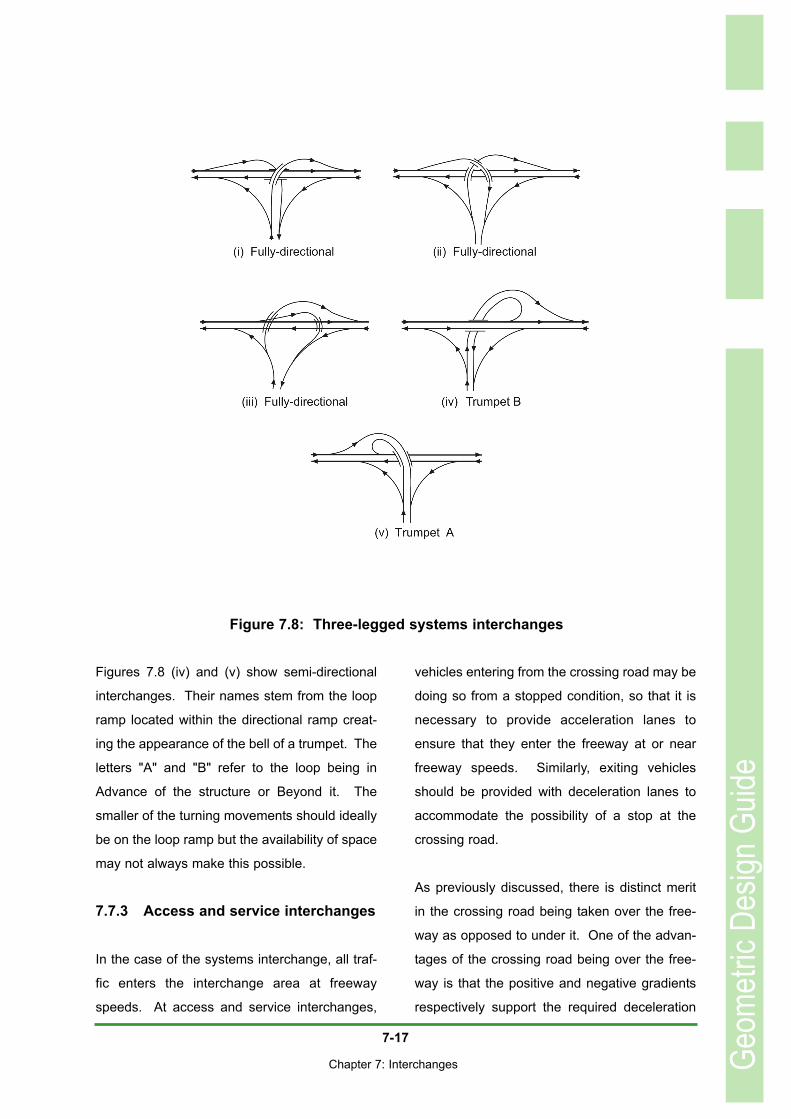
Three-legged interchanges
Various fully-directional and partially-directional
three legged interchanges are illustrated in
Figure 7.8. In Figure 7.8 (i), one single structure
providing a three-level separation is required.
Figure 7.8 (ii) also requires three levels of road-
way but spread across two structures hence
reducing the complexity of the structural design.
It is also possible with this layout to slightly
reduce the height through which vehicles have
to climb. Figure 7.8 (iii) illustrates a fully-direc-
tional interchange that requires only two but
widely separated structures. If North is
assumed as being at the top of the page, vehi-
cles turning from West to South have a slightly
longer path imposed on them so that this
should, ideally be the lesser turning volume.
Geom
etric
Desig
n Gu
ide
Figure 7.7: Four-legged systems interchanges
7-17
Chapter 7: Interchanges
Figures 7.8 (iv) and (v) show semi-directional
interchanges. Their names stem from the loop
ramp located within the directional ramp creat-
ing the appearance of the bell of a trumpet. The
letters "A" and "B" refer to the loop being in
Advance of the structure or Beyond it. The
smaller of the turning movements should ideally
be on the loop ramp but the availability of space
may not always make this possible.
7.7.3 Access and service interchanges
In the case of the systems interchange, all traf-
fic enters the interchange area at freeway
speeds. At access and service interchanges,
vehicles entering from the crossing road may be
doing so from a stopped condition, so that it is
necessary to provide acceleration lanes to
ensure that they enter the freeway at or near
freeway speeds. Similarly, exiting vehicles
should be provided with deceleration lanes to
accommodate the possibility of a stop at the
crossing road.
As previously discussed, there is distinct merit
in the crossing road being taken over the free-
way as opposed to under it. One of the advan-
tages of the crossing road being over the free-
way is that the positive and negative gradients
respectively support the required deceleration
Geom
etric
Desig
n Gu
ide
Figure 7.8: Three-legged systems interchanges
7-18
Chapter 7: Interchanges
and acceleration to and from the crossing road.
The final decision on the location of the crossing
road is, however, also dependent on other con-
trols such as topography and cost.
Access interchanges normally provide for all
turning movements. If, for any reason, it is
deemed necessary to eliminate some of the
turning movements, the return movement, for
any movement that is provided, should also be
provided. Movements excluded from a particu-
lar interchange should, desirably, be provided at
the next interchange upstream or downstream
as, without this provision, the community served
loses amenity.
There are only two basic interchange types that
are appropriate to access and service inter-
changes. These are the Diamond and the Par-
Clo interchanges. Each has a variety of possi-
ble configurations.
Trumpet interchanges used to be considered
suitable in cases where access was to provided
to one side only, for example to a bypass of a
town or village. In practice, however, once a
bypass has been built it does not take long
before development starts taking place on the
other side of the bypass. The three-legged
interchange then has to be converted into a
four-legged interchange. Conversion to a Par-
Clo can be achieved at relatively low cost.
Other than in the case of the Par-Clo AB, one of
the major movements is forced onto a loop
ramp. The resulting configuration is thus not
appropriate to the circumstances. In practice,
the interchange should be planned as a
Diamond in the first instance, even though the
crossing road, at the time of construction, stops
immediately beyond the interchange.
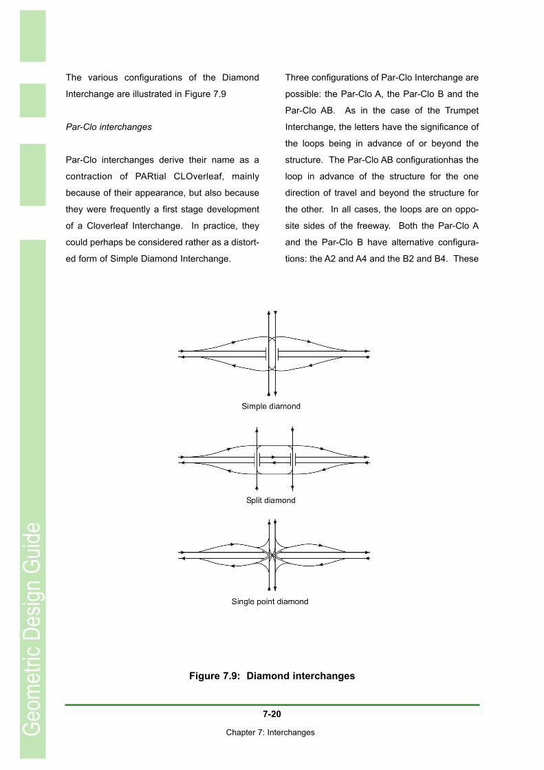
Diamond Interchanges
There are three basic forms of Diamond, being:
• The Simple Diamond;
• The Split Diamond, and the
• Single Point Interchange.
The Simple Diamond is easy for the driver to
understand and is economical in its use of
space. The major problem with this configura-
tion is that the right turn on to the crossing road
can cause queuing on the exit ramp. In extreme
cases, these queues can extend back onto the
freeway, creating a hazardous situation. Where
the traffic on the right turn is very heavy, it may
be necessary to consider placing it on a loop
ramp. This is the reverse of the situation on sys-
tems interchanges where it is the lesser vol-
umes that are located on loop ramps. It has the
advantage that the right turn is converted into a
left-turn at the crossing road ramp terminal. By
the provision of auxiliary lanes, this turn can
operate continuously without being impeded by
traffic signals.
The Simple Diamond can take one of two con-
figurations: the Narrow Diamond and the Wide
Diamond.
The Narrow Diamond is the form customarily
applied. In this configuration, the crossing road
ramp terminals are very close in plan to the free-
way shoulders to the extent that, where space is
heavily constricted, retaining walls are located
just outside the freeway shoulder breakpoints.
Apart from the problem of the right turn referred
Geom
etric
Desig
n Gu
ide
7-19
Chapter 7: Interchanges
to above, it can also suffer from a lack of inter-
section sight distance at the crossing road ramp
terminals. This problem arises when the cross-
ing road is taken over the freeway and is on a
minimum value crest curve on the structure. In
addition, the bridge balustrades can also inhibit
sight distance. In the case where the crossing
road ramp terminal is signalised, this is less of a
problem, although a vehicle accidentally or by
intent running the red signal could create a dan-
gerous situation.
The Wide Diamond was originally intended as a
form of stage construction, leading up to con-
version to a full Cloverleaf Interchange. The
time span between construction of the Diamond
and the intended conversion was, however, usu-
ally so great that, by the time the upgrade
became necessary, standards had increased to
the level whereby the loop ramps could not be
accommodated in the available space. The
decline in the popularity of the Cloverleaf has
led to the Wide Diamond also falling out of
favour.
The Wide Diamond has the problem of imposing
a long travel distance on right-turning vehicles
but is not without its advantages. The crossing
road ramp terminals are located at the start of
the approach fill to the structure. To achieve this
condition, the ramps have to be fairly long so
that queues backing up onto the freeway are
less likely than on the Narrow Diamond. The
crossing road ramp terminals are also at ground
level, which is a safer alternative than having
the intersections on a high fill. Finally, because
the ramp terminals are remote from the struc-
ture, intersection sight distance is usually not a
problem.
The Split Diamond can also take one of two
forms: the conventional Split and the transposed
Split. This configuration is normally used when
the crossing road takes the form of a one-way
pair. The problems of sight distance and
queues backing up are not normally experi-
enced on Split Diamonds and the most signifi-
cant drawback is that right-turning vehicles have
to traverse three intersections before being
clear of the interchange. It is also necessary to
construct frontage roads linking the two one-
way streets to provide a clear route for right-
turning vehicles.
The transposed Split has the ramps between the
two structures. This results in a very short dis-
tance between the entrance and succeeding
exit ramps, with significant problems of weaving
on the freeway. Scissor ramps are the extreme
example of the transposed Split. These require
either signalisation of the crossing of the two
ramps or a grade separation. The transposed
Split has little to recommend it and has fallen
into disuse, being discussed here only for com-
pleteness of the record.
The Single Point Interchange brings the four
ramps together at a point over the freeway. This
interchange is required where space is at a pre-
mium or where the volume of right-turning traffic
is very high. The principal operating difference
between the Single Point and the Simple
Diamond is that, in the former case, the right
turns take place outside each other and in the
latter they are "hooking" movements. The
capacity of the Single Point Interchange is thus
higher than that of the Simple Diamond. It does,
however, require a three-phase signal plan and
also presents pedestrians with wide unprotected
crossings.
Geom
etric
Desig
n Gu
ide
7-20
Chapter 7: Interchanges
The various configurations of the Diamond
Interchange are illustrated in Figure 7.9
Par-Clo interchanges
Par-Clo interchanges derive their name as a
contraction of PARtial CLOverleaf, mainly
because of their appearance, but also because
they were frequently a first stage development
of a Cloverleaf Interchange. In practice, they
could perhaps be considered rather as a distort-
ed form of Simple Diamond Interchange.
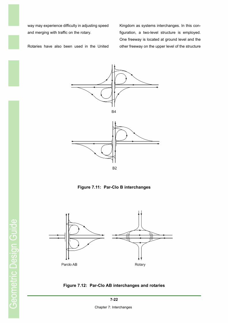
Three configurations of Par-Clo Interchange are
possible: the Par-Clo A, the Par-Clo B and the
Par-Clo AB. As in the case of the Trumpet
Interchange, the letters have the significance of
the loops being in advance of or beyond the
structure. The Par-Clo AB configurationhas the
loop in advance of the structure for the one
direction of travel and beyond the structure for
the other. In all cases, the loops are on oppo-
site sides of the freeway. Both the Par-Clo A
and the Par-Clo B have alternative configura-
tions: the A2 and A4 and the B2 and B4. These
Geom
etric
Desig
n Gu
ide
Figure 7.9: Diamond interchanges

7-21
Chapter 7: Interchanges
configurations refer to two quadrants only being
occupied or alternatively to all four quadrants
having ramps. The four-quadrant layout does
not enjoy much, if any, usage in South Africa.
The various layouts are illustrated in Figures
7.10, 7.11 and 7.12.
Internationally, the Par-Clo A4 is generally
regarded as being the preferred option for an
interchange between a freeway and a heavily
trafficked arterial. In the first instance, the loops
serve vehicles entering the freeway whereas, in
the case of the Par-Clo B, the high-speed vehi-
cles exiting the freeway are confronted by the
loop. This tends to surprise many drivers and
loops carrying exiting traffic have higher acci-
dent rates than the alternative layout. Secondly,
the left turn from the crossing road is remote
from the intersections on the crossing road and
the only conflict is between right-turning vehi-
cles exiting from the freeway and through traffic
on the crossing road. This makes two-phase
signal control possible.
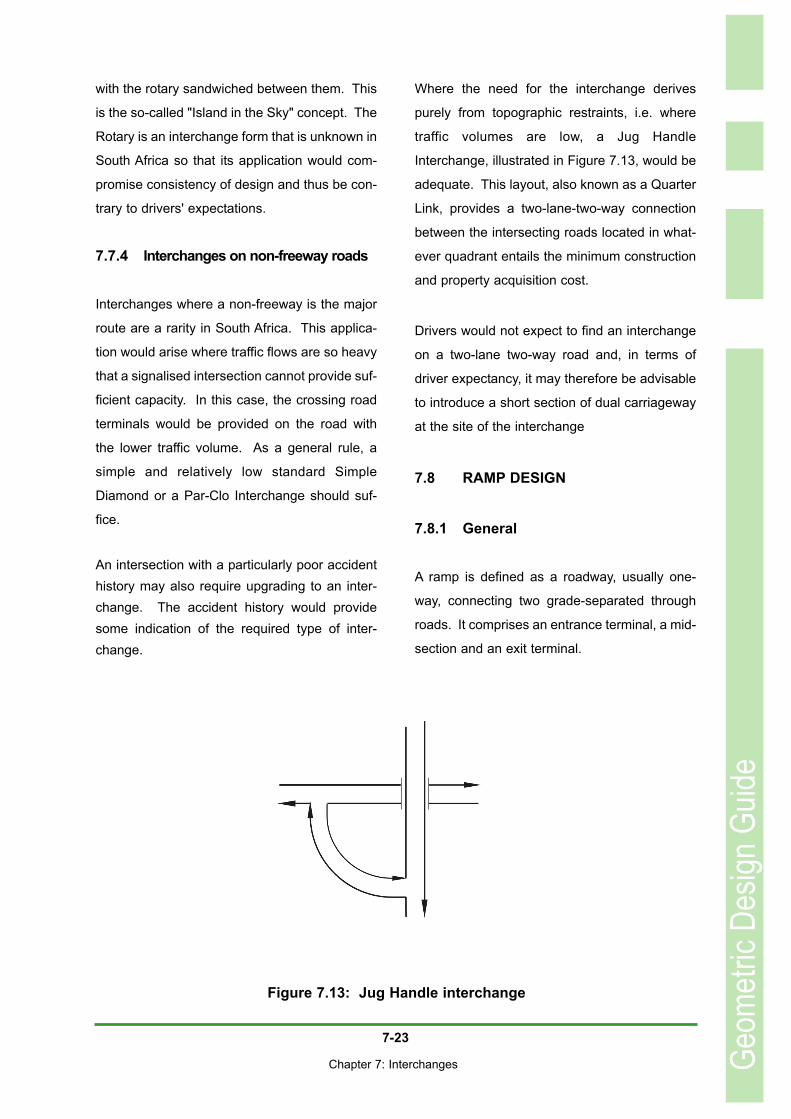
The Par-Clo AB is particularly useful in the situ-
ation where there are property or environmental
restrictions in two adjacent quadrants on the
same side of the crossing road. Examples
include a road running alongside a river or the
situation, frequently found in South Africa, of a
transportation corridor containing parallel road
and rail links in close proximity to each other.
The Rotary Interchange illustrated in Figure
7.12 has the benefit of eliminating intersections
on the crossing road, replacing them by short
weaving sections. Traffic exiting from the free-
Geom
etric
Desig
n Gu
ide
Figure 7.10: Par-Clo A interchanges
7-22
Chapter 7: Interchanges
way may experience difficulty in adjusting speed
and merging with traffic on the rotary.
Rotaries have also been used in the United
Kingdom as systems interchanges. In this con-
figuration, a two-level structure is employed.
One freeway is located at ground level and the
other freeway on the upper level of the structure
Geom
etric
Desig
n Gu
ide
Figure 7.11: Par-Clo B interchanges
Figure 7.12: Par-Clo AB interchanges and rotaries
7-23
Chapter 7: Interchanges
with the rotary sandwiched between them. This
is the so-called "Island in the Sky" concept. The
Rotary is an interchange form that is unknown in
South Africa so that its application would com-
promise consistency of design and thus be con-
trary to drivers' expectations.
7.7.4 Interchanges on non-freeway roads
Interchanges where a non-freeway is the major
route are a rarity in South Africa. This applica-
tion would arise where traffic flows are so heavy
that a signalised intersection cannot provide suf-
ficient capacity. In this case, the crossing road
terminals would be provided on the road with
the lower traffic volume. As a general rule, a
simple and relatively low standard Simple
Diamond or a Par-Clo Interchange should suf-
fice.
An intersection with a particularly poor accidenthistory may also require upgrading to an inter-change. The accident history would providesome indication of the required type of inter-change.
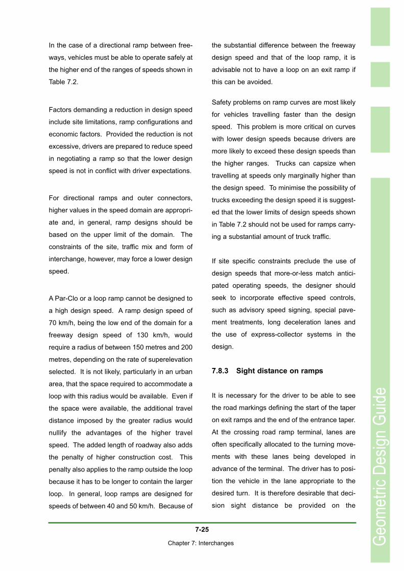
Where the need for the interchange derives
purely from topographic restraints, i.e. where
traffic volumes are low, a Jug Handle
Interchange, illustrated in Figure 7.13, would be
adequate. This layout, also known as a Quarter
Link, provides a two-lane-two-way connection
between the intersecting roads located in what-
ever quadrant entails the minimum construction
and property acquisition cost.
Drivers would not expect to find an interchange
on a two-lane two-way road and, in terms of
driver expectancy, it may therefore be advisable
to introduce a short section of dual carriageway
at the site of the interchange
7.8 RAMP DESIGN
7.8.1 General
A ramp is defined as a roadway, usually one-
way, connecting two grade-separated through
roads. It comprises an entrance terminal, a mid-
section and an exit terminal.
Geom
etric
Desig
n Gu
ide
Figure 7.13: Jug Handle interchange

7-24
Chapter 7: Interchanges
The general configuration of a ramp is deter-
mined prior to the interchange type being
selected. The specifics of its configuration,
being the horizontal and vertical alignment and
cross-section, are influenced by a number of
considerations such as traffic volume and com-
position, the geometric and operational charac-
teristics of the roads which it connects, the local
topography, traffic control devices and driver
expectations.
A variety of ramp configurations can be used.
These include:• The outer connector, which serves the
left turn and has free-flowing terminals at either end;
• The diamond ramp, serving both the left-and right-turns with a free-flowing termi-nal on the freeway and a stop-condition
terminal on the crossing-road;• The Par-Clo ramp, which serves the
right turn and has a free-flowing terminalon the freeway and a stop-condition ter-minal on the crossing road, with a 180O
loop between them;
• The loop ramp, serving the right turn
and which has free-flowing terminals at
both ends and a 270O degree loop
between them;• The directional ramp also serving the
right turn, with a curve only slightly in excess of 90O degrees and free-flowing terminals at either end, and
• The collector-distributor road intended to remove the weaving manoeuvre fromthe freeway.
The express-collector system discussed later is
a transfer roadway and is not an interchange
ramp.
7.8.2 Design speed
Guideline values for ramp design speeds are
given in Table 7.2. Strictly speaking, the design
speed of a ramp could vary across its length
from that of the freeway to that of the at-grade
intersection, with the design speed at any point
along the ramp matching the operating speed of
the vehicles accelerating to or decelerating from
the design speed of the freeway. The design
speeds given in the table apply to the controlling
curve on the mid-section of the ramp. The ramp
design speed is shown as a design domain
because of the wide variety of site conditions,
terminal types and ramp shapes.
Geom
etric
Desig
n Gu
ide
7-25
Chapter 7: Interchanges
In the case of a directional ramp between free-
ways, vehicles must be able to operate safely at
the higher end of the ranges of speeds shown in
Table 7.2.
Factors demanding a reduction in design speed
include site limitations, ramp configurations and
economic factors. Provided the reduction is not
excessive, drivers are prepared to reduce speed
in negotiating a ramp so that the lower design
speed is not in conflict with driver expectations.
For directional ramps and outer connectors,
higher values in the speed domain are appropri-
ate and, in general, ramp designs should be
based on the upper limit of the domain. The
constraints of the site, traffic mix and form of
interchange, however, may force a lower design
speed.
A Par-Clo or a loop ramp cannot be designed to
a high design speed. A ramp design speed of
70 km/h, being the low end of the domain for a
freeway design speed of 130 km/h, would
require a radius of between 150 metres and 200
metres, depending on the rate of superelevation
selected. It is not likely, particularly in an urban
area, that the space required to accommodate a
loop with this radius would be available. Even if
the space were available, the additional travel
distance imposed by the greater radius would
nullify the advantages of the higher travel
speed. The added length of roadway also adds
the penalty of higher construction cost. This
penalty also applies to the ramp outside the loop
because it has to be longer to contain the larger
loop. In general, loop ramps are designed for
speeds of between 40 and 50 km/h. Because of
the substantial difference between the freeway
design speed and that of the loop ramp, it is
advisable not to have a loop on an exit ramp if
this can be avoided.
Safety problems on ramp curves are most likely
for vehicles travelling faster than the design
speed. This problem is more critical on curves
with lower design speeds because drivers are
more likely to exceed these design speeds than
the higher ranges. Trucks can capsize when
travelling at speeds only marginally higher than
the design speed. To minimise the possibility of
trucks exceeding the design speed it is suggest-
ed that the lower limits of design speeds shown
in Table 7.2 should not be used for ramps carry-
ing a substantial amount of truck traffic.
If site specific constraints preclude the use of
design speeds that more-or-less match antici-
pated operating speeds, the designer should
seek to incorporate effective speed controls,
such as advisory speed signing, special pave-
ment treatments, long deceleration lanes and
the use of express-collector systems in the
design.
7.8.3 Sight distance on ramps
It is necessary for the driver to be able to see
the road markings defining the start of the taper
on exit ramps and the end of the entrance taper.
At the crossing road ramp terminal, lanes are
often specifically allocated to the turning move-
ments with these lanes being developed in
advance of the terminal. The driver has to posi-
tion the vehicle in the lane appropriate to the
desired turn. It is therefore desirable that deci-
sion sight distance be provided on the
Geom
etric
Desig
n Gu
ide

7-26
Chapter 7: Interchanges
approaches to the ramp as well as across its
length.
Appropriate values of decision sight distance
are given in Table 3.7.
7.8.4 Horizontal alignment
Minimum radii of horizontal curvature on ramps
are as shown in Table 4.1 for various values of
emax. In general, the higher values of emax are
used in freeway design and the selected value
should also be applied to the ramps.
Achieving the step down of radii from higher to
lower design speeds on a loop may require the
application of compound curves. In general, the
ratio between successive radii should be 1,5 : 1
and, as a further refinement, they could be con-
nected by transition curves. The length of each
arc is selected to allow for deceleration to the
speed appropriate to the next radius at the entry
to that arc. In the case of stepping up through
successive radii, the same ratio applies but the
design speed for the radius selected should
match the desired speed at the far end of each
arc.
It is recommended that the designer develops a
speed profile for the loop and bases the selec-
tion of radii and arc lengths on this speed profile.
As a rough rule of thumb, the length of each arc
should be approximately a third of its radius.
If a crossover crown line, discussed below, is
not used, the crossfall on the exit or entrance
taper between the Yellow Line Break Point and
the nose is controlled by that on the through
lanes. Superelevation development can thus
only commence at the nose. The distance
required to achieve the appropriate supereleva-
tion thus determines the earliest possible loca-
tion of the first curve on the ramp.
Ramps are relatively short and the radii of
curves on ramps often approach the minimum
for the selected design speed. Furthermore, if
there is more than one curve on a ramp, the dis-
tance between the successive curves will be
short. Under these restrictive conditions, transi-
tion curves should be considered.
Ramps are seldom, if ever, cambered and
superelevation typically involves rotation around
one of the lane edges. Drivers tend to position
their vehicles relative to the inside edge of any
curve being traversed, i.e. they steer towards
the inside of the curve rather than away from the
outside. For aesthetic reasons, the inside edge
should thus present a smoothly flowing three-
dimensional alignment with the outside edge ris-
ing and falling to provide the superelevation.
Where a ramp has an S- or reverse curve align-
ment, it follows that first one edge and then the
other will be the centre of rotation, with the
changeover taking place at the point of zero
crossfall.
In view of the restricted distances within which
superelevation has to be developed, the
crossover crown line is a useful device towards
rapid development. A crossover crown is a line
at which an instantaneous change of crossfall
takes place and which runs diagonally across
the lane. The crossover crown could, for exam-
ple, be located along the yellow line defining the
edge of the left lane of the freeway, thus
Geom
etric
Desig
n Gu
ide

7-27
Chapter 7: Interchanges
enabling initiation of superelevation for the first
curve on the ramp earlier than would otherwise
be the case. The crossover crown should, how-
ever, be used with caution as it may pose a
problem to the driver, particularly to the driver of
a vehicle with a high load. This is because the
vehicle will sway as it traverses the crossover
crown and, in extreme cases, may prove difficult
to control. The algebraic difference in slope
across the crossover crown should thus not
exceed four to five per cent.
7.8.5 Vertical alignment
Gradients
The profile of a ramp typically comprises a mid-
section with an appreciable gradient coupled
with terminals where the gradient is controlled
by the adjacent road. If the crossing road is
over the freeway, the positive gradient on the
off-ramps will assist a rapid but comfortable
deceleration and the negative gradient on the
on-ramp will support acceleration to freeway
speeds. In theory, thus, the higher the value of
gradient, the better. Values of gradient up to
eight per cent can be considered but, for prefer-
ence, gradients should not exceed six per cent.
Diamond ramps are usually fairly short, possibly
having as little as 120 to 360 metres between
the nose and the crossing road. The effect of
the midsection gradient, while possibly helpful,
is thus restricted. However, a steep gradient (8
per cent) in conjunction with a high value of
superelevation (10 per cent) would have a
resultant of 12,8 per cent at an angle of 53O to
the centreline of the ramp. This would not con-
tribute to drivers' sense of safety. In addition,
the drivers of slow-moving trucks would have to
steer outwards to a marked extent to maintain
their path within the limits of the ramp width.
This could create some difficulty for them. It is
suggested that designers seek a combination of
superelevation and gradient such that the gradi-
ent of the resultant is less than ten per cent.
Table 7.3 provides an indication of the gradients
of the resultants of combinations of supereleva-
tion and longitudinal gradient.
The combinations of gradient and supereleva-
tion shown shaded in Table 7.3 should be avoid-
ed.
Curves
As suggested above, decision sight distance
should be available at critical points on ramps.
The K-values of crest curves required to meet
this requirement are given in Table 7.4.
Geom
etric
Desig
n Gu
ide
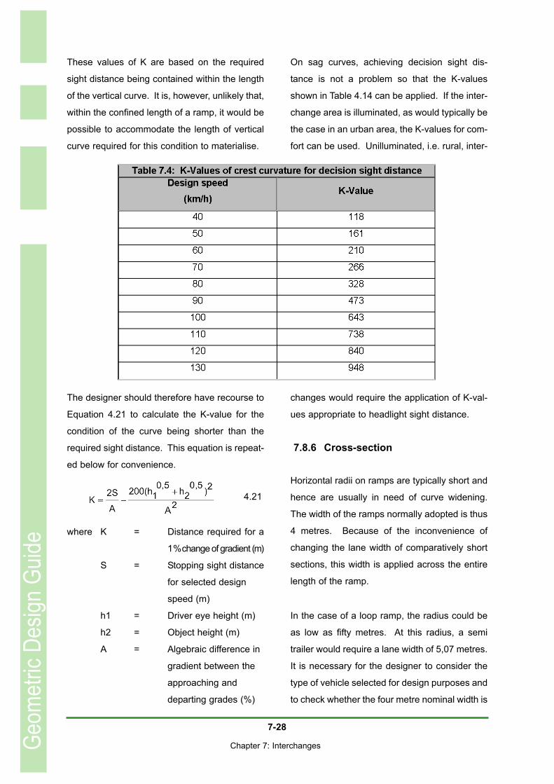
7-28
Chapter 7: Interchanges
These values of K are based on the required
sight distance being contained within the length
of the vertical curve. It is, however, unlikely that,
within the confined length of a ramp, it would be
possible to accommodate the length of vertical
curve required for this condition to materialise.
The designer should therefore have recourse to
Equation 4.21 to calculate the K-value for the
condition of the curve being shorter than the
required sight distance. This equation is repeat-
ed below for convenience.
where K = Distance required for a
1 % change of gradient (m)
S = Stopping sight distance
for selected design
speed (m)
h1 = Driver eye height (m)
h2 = Object height (m)
A = Algebraic difference in
gradient between the
approaching and
departing grades (%)
On sag curves, achieving decision sight dis-
tance is not a problem so that the K-values
shown in Table 4.14 can be applied. If the inter-
change area is illuminated, as would typically be
the case in an urban area, the K-values for com-
fort can be used. Unilluminated, i.e. rural, inter-
changes would require the application of K-val-
ues appropriate to headlight sight distance.
7.8.6 Cross-section
Horizontal radii on ramps are typically short and
hence are usually in need of curve widening.
The width of the ramps normally adopted is thus
4 metres. Because of the inconvenience of
changing the lane width of comparatively short
sections, this width is applied across the entire
length of the ramp.
In the case of a loop ramp, the radius could be
as low as fifty metres. At this radius, a semi
trailer would require a lane width of 5,07 metres.
It is necessary for the designer to consider the
type of vehicle selected for design purposes and
to check whether the four metre nominal width is
Geom
etric
Desig
n Gu
ide
4.21
7-29
Chapter 7: Interchanges
adequate. If semi trailers are infrequent users
of the ramp, encroachment on the shoulders
could be considered.
The calculation of required lane width is
described in detail in Section 4.2.6. As sug-
gested above, regardless of the width required,
it should be applied across the entire length of
the ramp.
Ramp shoulders typically have a width of the
order of 2 metres, with this width applying both
to the inner and to the outer shoulder. In con-
junction with the nominal lane width of 4 metres,
the total roadway width is thus 8 metres. This
width would allow comfortably for a truck to pass
a broken-down truck. In addition, it would pro-
vide drivers with some sense of security in the
cases where the ramp is on a high fill.
7.8.7 Terminals
The crossing road ramp terminals may be free-
flowing, in which case their design is as dis-
cussed below. Crossing road ramp terminals
that are at-grade intersections should be
designed according to the recommendations
contained in Chapter 6. It is worth noting that,
from an operational point of view, what appears
to be a four-legged intersection, e.g. the cross-
ing road ramp terminals on a Diamond
Interchange, is, in fact, two three-legged inter-
sections back-to-back. Ideally, the crossing
road ramp terminal should be channelised to
reduce the possibility of wrong-way driving.
Vehicles entering or exiting from a freeway
should be able to do so at approximately the
operating speed of the freeway. Given the fact
that the crossing road terminal is invariably a
signalised or stop control at-grade intersection,
the change in speed across the ramp is sub-
stantial. Provision should thus be made for
acceleration and deceleration to take place
clear of the freeway so as to minimise interfer-
ence with the through traffic and reduce the
potential for crashes. The auxiliary lanes pro-
vided to accommodate this are referred to as
speed-change lanes or acceleration or deceler-
ation lanes. These terms describe the area
adjacent to the travelled way of the freeway,
including that portion of the ramp taper where a
merging vehicle is still clear of the through lane,
and do not imply a definite lane of uniform width.
The speed change lane should have sufficient
length to allow the necessary adjustment in
speed to be made in a comfortable manner and,
in the case of an acceleration lane, there should
also be sufficient length for the driver to find and
manoeuvre into a gap in the through traffic
stream before reaching the end of the accelera-
tion lane. The length of the speed change lane
is based on:• The design speed on the through lane,
i.e. the speed at which vehicles enter orexit from the through lanes;
• The control speed of the ramp midsec-tion, i.e. the design speed of the small-est radius curve on the ramp, and
• The tempo of acceleration or decelera-tion applied on the speed change lane.
In Chapter 3, reference was made to a deceler-
ation rate of 3 m/s2 as the basis for the calcula-
tion of stopping sight distance. Research has
shown that deceleration rates applied to off-
ramps are a function of the freeway design
speed and the ramp control speed. As both
speeds increase, so does the deceleration rate,
Geom
etric
Desig
n Gu
ide
7-30
Chapter 7: Interchanges
which varies between 1,0 m/s2 and 2,0 m/s2.
For convenience, the deceleration rate used to
develop Table 7.5 has been set at 2,0 m/s2.
Deceleration should only commence once the
exiting vehicle is clear of the through lane.
Assuming that a vehicle with a width of 2,5
metres is correctly positioned relative to the
ramp edge line to be centrally located within an
ultimate ramp width of 4 metres, its tail end will
clear the edge of the through lane at a distance,
L, from the Yellow Line Break Point where
L = 3,2 / T
with T = Taper rate (as listed in
Table 7.7)
The maximum legal length of any vehicle on
South African roads is 22 metres and this should
be added to the distance, L, to establish the dis-
tance from the Yellow Line Break Point, at which
the deceleration can commence so that
LT = 3,2/T + 22
Values of LT, are listed in Table 7.5. From this
table it follows that, in the case of a diamond
ramp without curves, the distance from the
Yellow Line Break Point to the crossing road
ramp terminal should be not less than 437
metres.
The acceleration rate can, according to
American literature, be taken as 0,7 m/s2. The
length of the acceleration lane is thus as shown
in Table 7.6. An important feature of the accel-
eration lane is the gap acceptance length, which
should be a minimum of 100 metres to 150
metres, depending on the nose width. The
length of the entering vehicle is not relevant in
determination of the taper length.
The lengths of the deceleration and acceleration
lanes shown in Tables 7.5 and 7.6 apply to gra-
dients of between - 3 per cent and + 3 per cent.
Acceleration lanes will have to be longer on
upgrades and may be made shorter on down-
grades, with the reverse applying to decelera-
tion lanes.
The actual entrance or exit points between the
freeway and the ramp can take the form of a
taper or a parallel lane. The parallel lane has
the problem of forcing a reverse curve path,
possibly followed after the nose by a further
curve to the left, whereas the taper involves only
a single change of direction. As such, drivers
prefer the taper. In cases where an extended
acceleration or deceleration distance is
required, for example where the crossing road
passes under the freeway resulting in the on-
ramp being on an upgrade and the off-ramp on
a downgrade, a straight taper would result in an
inordinately long ramp. The parallel lane allows
the speed change to take place in an auxiliary
lane immediately adjacent to the through lanes
thus reducing the spatial demands of the inter-
change.
Furthermore, in the case of the on-ramp, the
parallel configuration provides an extended dis-
tance to find a gap in the adjacent traffic stream.
Typical configurations of on- and off-ramp termi-
nals are illustrated in Figures 7.14 to 7.17.
Taper
Two different criteria apply to the selection of the
taper rate, depending on whether the ramp is an
Geom
etric
Desig
n Gu
ide
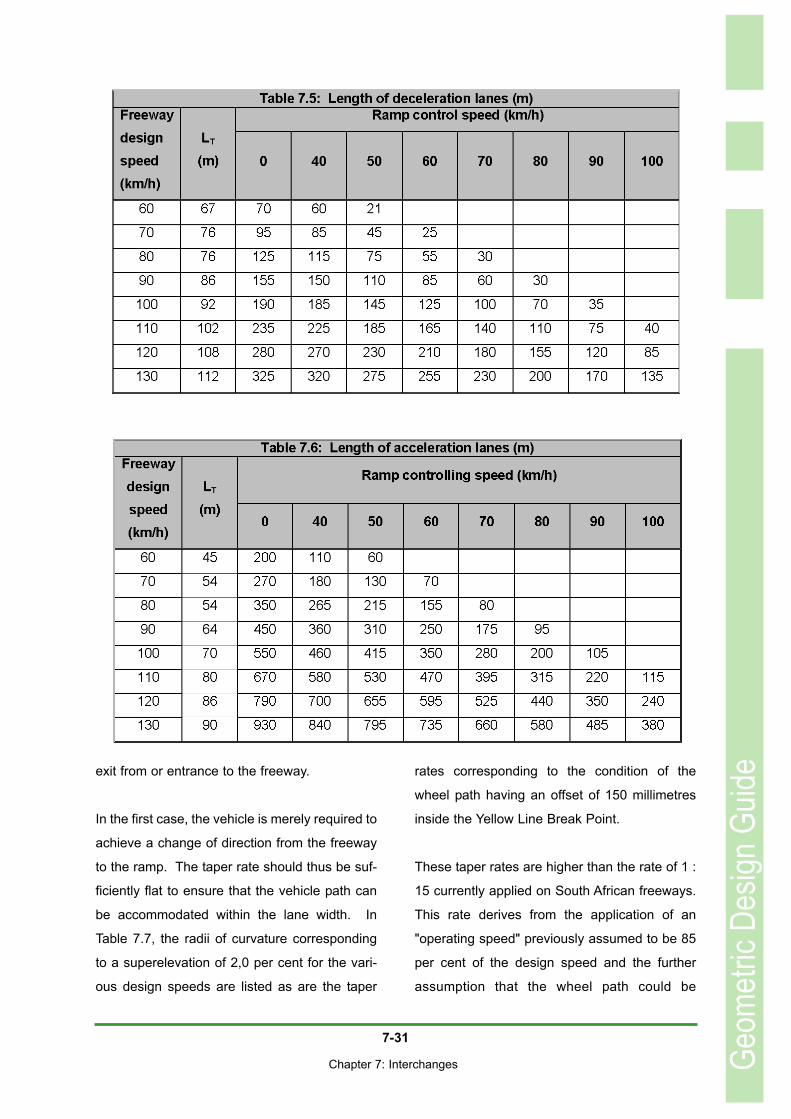
7-31
Chapter 7: Interchanges
exit from or entrance to the freeway.
In the first case, the vehicle is merely required to
achieve a change of direction from the freeway
to the ramp. The taper rate should thus be suf-
ficiently flat to ensure that the vehicle path can
be accommodated within the lane width. In
Table 7.7, the radii of curvature corresponding
to a superelevation of 2,0 per cent for the vari-
ous design speeds are listed as are the taper
rates corresponding to the condition of the
wheel path having an offset of 150 millimetres
inside the Yellow Line Break Point.
These taper rates are higher than the rate of 1 :
15 currently applied on South African freeways.
This rate derives from the application of an
"operating speed" previously assumed to be 85
per cent of the design speed and the further
assumption that the wheel path could be
Geom
etric
Desig
n Gu
ide
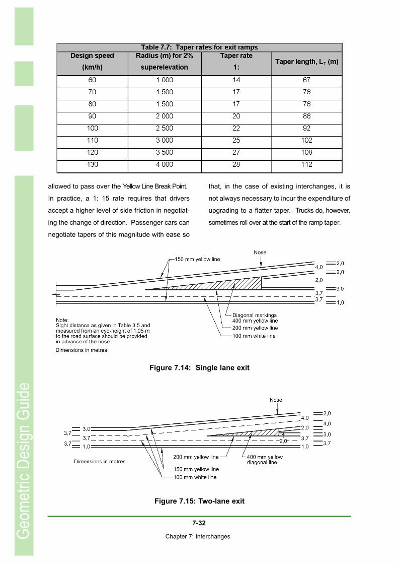
7-32
Chapter 7: Interchanges
allowed to pass over the Yellow Line Break Point.
In practice, a 1: 15 rate requires that drivers
accept a higher level of side friction in negotiat-
ing the change of direction. Passenger cars can
negotiate tapers of this magnitude with ease so
that, in the case of existing interchanges, it is
not always necessary to incur the expenditure of
upgrading to a flatter taper. Trucks do, however,
sometimes roll over at the start of the ramp taper.
Geom
etric
Desig
n Gu
ide
Figure 7.14: Single lane exit
Figure 7.15: Two-lane exit
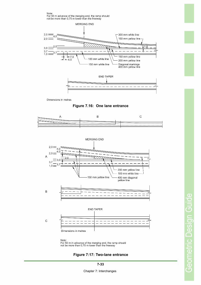
7-33
Chapter 7: Interchanges Geom
etric
Desig
n Gu
ide
Figure 7.16: One lane entrance
Figure 7:17: Two-lane entrance
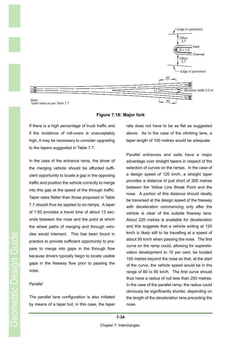
7-34
Chapter 7: Interchanges
If there is a high percentage of truck traffic and
if the incidence of roll-overs is unacceptably
high, it may be necessary to consider upgrading
to the tapers suggested in Table 7.7.
In the case of the entrance ramp, the driver of
the merging vehicle should be afforded suffi-
cient opportunity to locate a gap in the opposing
traffic and position the vehicle correctly to merge
into this gap at the speed of the through traffic.
Taper rates flatter than those proposed in Table
7.7 should thus be applied to on-ramps. A taper
of 1:50 provides a travel time of about 13 sec-
onds between the nose and the point at which
the wheel paths of merging and through vehi-
cles would intersect. This has been found in
practice to provide sufficient opportunity to pre-
pare to merge into gaps in the through flow
because drivers typically begin to locate usable
gaps in the freeway flow prior to passing the
nose.
Parallel
The parallel lane configuration is also initiated
by means of a taper but, in this case, the taper
rate does not have to be as flat as suggested
above. As in the case of the climbing lane, a
taper length of 100 metres would be adequate.
Parallel entrances and exits have a majoradvantage over straight tapers in respect of theselection of curves on the ramps. In the case ofa design speed of 120 km/h, a straight taperprovides a distance of just short of 300 metresbetween the Yellow Line Break Point and thenose. A portion of this distance should ideallybe traversed at the design speed of the freewaywith deceleration commencing only after thevehicle is clear of the outside freeway lane.About 220 metres is available for decelerationand this suggests that a vehicle exiting at 120km/h is likely still to be travelling at a speed ofabout 95 km/h when passing the nose. The firstcurve on the ramp could, allowing for superele-vation development to 10 per cent, be located100 metres beyond the nose so that, at the startof the curve, the vehicle speed would be in therange of 80 to 90 km/h. The first curve shouldthus have a radius of not less than 250 metres.In the case of the parallel ramp, the radius couldobviously be significantly shorter, depending onthe length of the deceleration lane preceding thenose.
Geom
etric
Desig
n Gu
ide
Figure 7.18: Major fork
7-35
Chapter 7: Interchanges
7.9 COLLECTOR - DISTRIBUTOR ROADS
Collector-distributor roads are typically applied
to the situation where weaving manoeuvres
would be disruptive if allowed to occur on the
freeway. Their most common application, there-
fore, is at Cloverleaf interchanges. The exit and
entrance tapers are identical to those applied to
any other ramps. The major difference between
Cloverleaf interchange C-D roads and other
ramps is that they involve two exits and two
entrances in quick succession. The two exits
are, firstly, from the freeway and, secondly, the
split between vehicles turning to the left and
those intending to turn to the right. The two
entrances are, firstly, the merge between the
two turning movements towards the freeway
and, secondly, the merge with the freeway
through traffic.
The distance between the successive exits
should be based on signing requirements so as
to afford drivers adequate time to establish
whether they have to turn to the right or to the
left to reach their destination. Nine seconds is
generally considered adequate for this purpose
and seeing that vehicles may be travelling at the
design speed of the freeway as they pass the
nose of the first exit, the distance between the
noses should desirably be based on this speed.
The distance between successive entrances is
based on the length required for the accelera-
tion lane length quoted in Table 7.6.
7.10 OTHER INTERCHANGE DESIGN FEATURES
7.10.1 Ramp metering
Ramp metering consists of traffic signals
installed on entrance ramps in advance of the
entrance terminal to control the number of vehi-
cles entering the freeway. The traffic signals
may be pretimed or traffic-actuated to release
the entering vehicles individually or in platoons.
It is applied to restrict the number of vehicles
that are allowed to enter a freeway in order to
ensure an acceptable level of service on the
freeway or to ensure that the capacity of the
freeway is not exceeded. The need for ramp
metering may arise owing to factors such as:
Recurring congestion because traffic
demand exceeds the provision of road
infrastructure in an area;
Sporadic congestion on isolated sec-
tions of a freeway because of short term
traffic loads from special events, normal-
ly of a recreational nature;
As part of an incident management sys-
tem to assist in situations where a acci-
dent downstream of the entrance ramp
causes a temporary drop in the capacity
of the freeway; and
Optimising traffic flow on freeways
Ramp metering also supports local transporta-tion management objectives such as:• Priority treatments with higher levels of
service for High Occupancy Vehicles; and
• Redistribution of access demand to other on-ramps.
It is important to realise that ramp meteringshould be considered a last resort rather than asa first option in securing an adequate level ofservice on the freeway. Prior to its implementa-
Geom
etric
Desig
n Gu
ide
•
•
•
•
7-36
Chapter 7: Interchanges
tion, all alternate means of improving the capac-ity of the freeway or its operating characteristicsor reducing the traffic demand on the freewayshould be explored. The application of rampmetering should be preceded by an engineeringanalysis of the physical and traffic conditions onthe freeway facilities likely to be affected. Thesefacilities include the ramps, the ramp terminalsand the local streets likely to be affected bymetering as well as the freeway sectioninvolved.
The stopline should be placed sufficiently in
advance of the point at which ramp traffic will
enter the freeway to allow vehicles to accelerate
to approximately the operating speed of the
freeway, as would normally be required for the
design of ramps. It will also be necessary to
ensure that the ramp has sufficient storage to
accommodate the vehicles queuing upstream of
the traffic signal.
The above requirement will almost certainly lead
to a need for reconstruction of any ramp that is
to be metered. The length of on-ramps is typi-
cally determined by the distance required to
enable a vehicle to accelerate to freeway
speeds. Without reconstruction, this could result
in the ramp metering actually being installed at
the crossing-road ramp terminal.
7.10.2 Express-collector systems
Express-collector systems are used where traf-fic volumes dictate a freeway width greater thanfour lanes in each direction. The purpose of theexpress-collector is to eliminate weaving on themainline lanes by limiting the number ofentrance and exit points while satisfying thedemand for access to the freeway system.
An express-collector system could, for example,
be started upstream of one interchange and run
through it and the following, possibly closely
spaced, interchange, terminating downstream
of the second. The terminals at either end of the
express-collector system would have the same
standards as applied to conventional on- and
off-ramps. The interchange ramps are connect-
ed to the express-collector system and not
directly to the freeway mainline lanes.
Traffic volumes and speeds on the express-col-
lector roads are typically much lower than those
found on the mainline lanes, allowing for lower
standards being applied to the ramp geometry
of the intervening interchanges.
The minimum configuration for an express-col-
lector system is to have a two-lane C-D road on
either side of a freeway with two lanes in each
direction. The usual configuration has more than
two mainline lanes in each direction
A similar configuration is known as a dual-divid-
ed freeway, sometimes referred to as a dual-
dual freeway. In this case, the C-D roads are
taken over a considerable distance and may
have more than two lanes. Furthermore, con-
nections are provided at intervals between the
outer and the core lanes along the length of the
freeway. These, unfortunately, create the effect
of right-side entrances and exits to and from the
outer lanes and are thus contrary to drivers'
expectations. The geometry of the situation is
otherwise similar to that of the express-collector
system.
Geom
etric
Desig
n Gu
ide