table of contents - panasonic · 2 tld badge systems - overview panasonic tld badge systems can be...
TRANSCRIPT

1
Overview 2-3
Advanced Thermoluminescent System 4
Optical Heating System 5
UD-800Composite Type TL Badge 6-7
UD-716AGLCompact Type Automatic Reader 8-9
UD-7900Computerized Type TL Badge Automatic Reader with Built-in Auto Changer
10-11
UD-794Computerized Type TL Badge Automatic Irradiator with Built-in Auto Changer
12-13
ZP-145Alarm Pocket Dosimeter 14-15
Panasonic Dosimeter & Readers - Statement 16-25
Table of ContentsDOSIMETRYDOSIMETRY
2
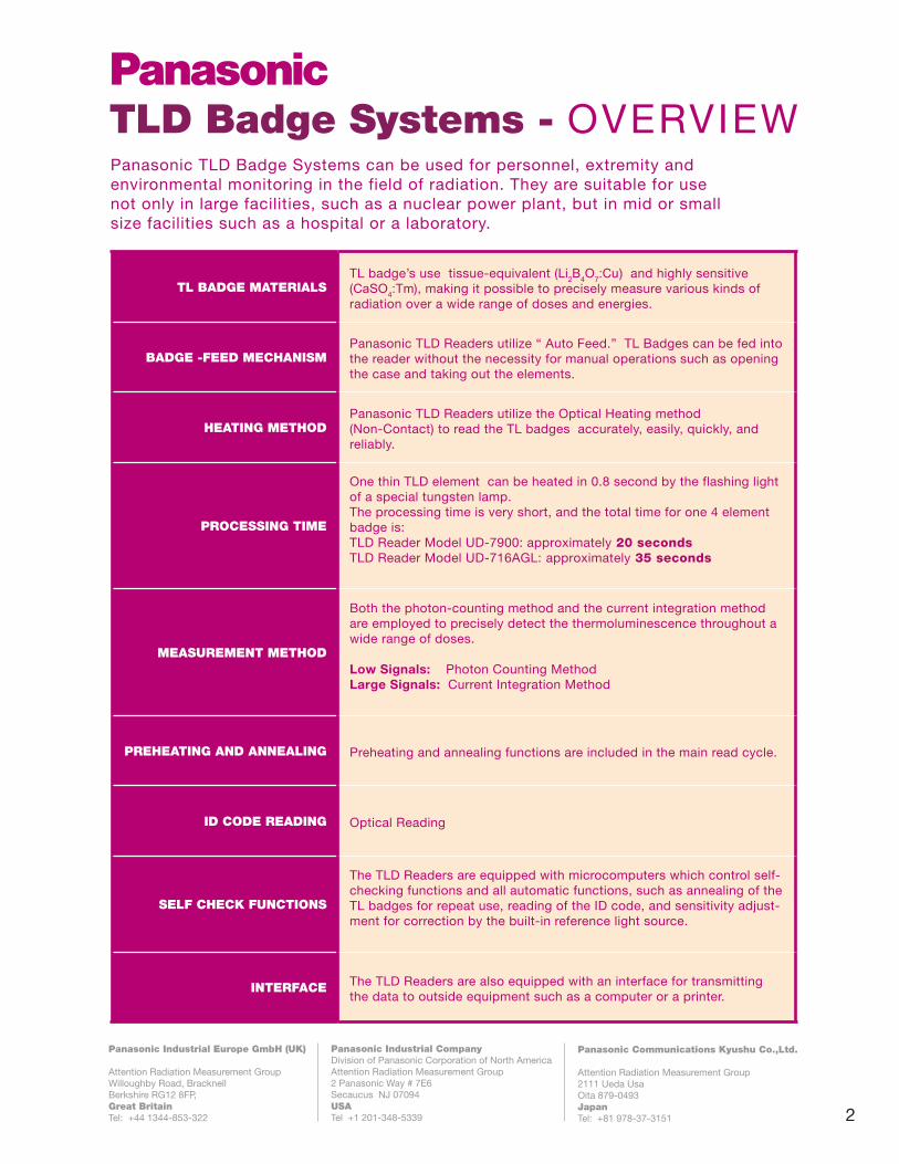
TLD Badge Systems - OVERVIEW Panasonic TLD Badge Systems can be used for personnel, extremity and environmental monitoring in the field of radiation. They are suitable for use not only in large facilities, such as a nuclear power plant, but in mid or small size facilities such as a hospital or a laboratory.
Panasonic Industrial CompanyDivision of Panasonic Corporation of North AmericaAttention Radiation Measurement Group 2 Panasonic Way # 7E6 Secaucus NJ 07094 USA Tel +1 201-348-5339
Panasonic Industrial Europe GmbH (UK)
Attention Radiation Measurement Group Willoughby Road, BracknellBerkshire RG12 8FP, Great BritainTel: +44 1344-853-322
Panasonic Communications Kyushu Co.,Ltd.
Attention Radiation Measurement Group 2111 Ueda Usa Oita 879-0493 JapanTel: +81 978-37-3151
TL BADGE MATERIALSTL badge’s use tissue-equivalent (Li2B4O7:Cu) and highly sensitive (CaSO4:Tm), making it possible to precisely measure various kinds of radiation over a wide range of doses and energies.
BADGE -FEED MECHANISMPanasonic TLD Readers utilize “ Auto Feed.” TL Badges can be fed into the reader without the necessity for manual operations such as opening the case and taking out the elements.
HEATING METHODPanasonic TLD Readers utilize the Optical Heating method (Non-Contact) to read the TL badges accurately, easily, quickly, and reliably.
PROCESSING TIME
One thin TLD element can be heated in 0.8 second by the flashing light of a special tungsten lamp.The processing time is very short, and the total time for one 4 element badge is:TLD Reader Model UD-7900: approximately 20 seconds TLD Reader Model UD-716AGL: approximately 35 seconds
MEASUREMENT METHOD
Both the photon-counting method and the current integration method are employed to precisely detect the thermoluminescence throughout a wide range of doses.
Low Signals: Photon Counting Method Large Signals: Current Integration Method
PREHEATING AND ANNEALING Preheating and annealing functions are included in the main read cycle.
ID CODE READING Optical Reading
SELF CHECK FUNCTIONS
The TLD Readers are equipped with microcomputers which control self-checking functions and all automatic functions, such as annealing of the TL badges for repeat use, reading of the ID code, and sensitivity adjust-ment for correction by the built-in reference light source.
INTERFACE The TLD Readers are also equipped with an interface for transmitting the data to outside equipment such as a computer or a printer.

3
TLD Badge Systems - OVERVIEW Panasonic TLD Badge Systems can be used for personnel, extremity and environmental monitoring in the field of radiation. They are suitable for use not only in large facilities, such as a nuclear power plant, but in mid or small size facilities such as a hospital or a laboratory.
Panasonic Industrial CompanyDivision of Panasonic Corporation of North AmericaAttention Radiation Measurement Group 2 Panasonic Way # 7E6 Secaucus NJ 07094 USA Tel +1 201-348-5339
Panasonic Industrial Europe GmbH (UK)
Attention Radiation Measurement Group Willoughby Road, BracknellBerkshire RG12 8FP, Great BritainTel: +44 1344-853-322
Panasonic Communications Kyushu Co.,Ltd.
Attention Radiation Measurement Group 2111 Ueda Usa Oita 879-0493 JapanTel: +81 978-37-3151
TL BADGE MATERIALSTL badge’s use tissue-equivalent (Li2B4O7:Cu) and highly sensitive (CaSO4:Tm), making it possible to precisely measure various kinds of radiation over a wide range of doses and energies.
BADGE -FEED MECHANISMPanasonic TLD Readers utilize “ Auto Feed.” TL Badges can be fed into the reader without the necessity for manual operations such as opening the case and taking out the elements.
HEATING METHODPanasonic TLD Readers utilize the Optical Heating method (Non-Contact) to read the TL badges accurately, easily, quickly, and reliably.
PROCESSING TIME
One thin TLD element can be heated in 0.8 second by the flashing light of a special tungsten lamp.The processing time is very short, and the total time for one 4 element badge is:TLD Reader Model UD-7900: approximately 20 seconds TLD Reader Model UD-716AGL: approximately 35 seconds
MEASUREMENT METHOD
Both the photon-counting method and the current integration method are employed to precisely detect the thermoluminescence throughout a wide range of doses.
Low Signals: Photon Counting Method Large Signals: Current Integration Method
PREHEATING AND ANNEALING Preheating and annealing functions are included in the main read cycle.
ID CODE READING Optical Reading
SELF CHECK FUNCTIONS
The TLD Readers are equipped with microcomputers which control self-checking functions and all automatic functions, such as annealing of the TL badges for repeat use, reading of the ID code, and sensitivity adjust-ment for correction by the built-in reference light source.
INTERFACE The TLD Readers are also equipped with an interface for transmitting the data to outside equipment such as a computer or a printer.
Computerized Type Automatic Irradiator with Built-In Auto-changer
UD-794TLD Badge Systems: Overview
Element No. PurposeThermoluminescent
materialRadiation Shield
Measurement range
1st element Skin dose Li2B4O7: Cu Thin window10 mRem ~ 1000Rem100µSv ~ 10 Sv
2nd element 10keV ~ 10 MeV Li2B4O7: Cu Plastic10mR ~ 1000R100µSv ~ 10 Sv
3rd element 25 keV ~ 10 MeV CaSO4: Tm Plastic1mR ~ 50R10µSv ~ 500mSv
4th element 25 keV ~ 10 MeV CaSO4: Tm Lead + Plastic1mR ~ 50R10µSv ~ 500mSv
Panasonic Industrial CompanyDivision of Panasonic Corporation of North AmericaAttention Radiation Measurement Group 2 Panasonic Way # 7E6 Secaucus NJ 07094 USA Tel +1 201-348-5339
Panasonic Industrial Europe GmbH (UK)
Attention Radiation Measurement Group Willoughby Road, BracknellBerkshire RG12 8FP, Great BritainTel: +44 1344-853-322
Panasonic Communications Kyushu Co.,Ltd.
Attention Radiation Measurement Group 2111 Ueda Usa Oita 879-0493 JapanTel: +81 978-37-3151
l

4
The Panasonic TL-Badge is a small, reliable dosimeter designed for superior accuracy, easy handling, cleanliness and resistance to mechani-cal impact.
Thin elements of tissue-equivalentLi2B4O7:Cu and ultra-sensitive CaSO4 : Tm are encapsulated within a case containing the appropriate filters and optical ID-code.
Panasonic TLDs have two differ-ent phosphors, allowing energies and particles to be detected.
D O S I M E TE R C O N S TR U C TI O N
Typical configuration is a four-element plate enclosed with plastic and lead filters.
This composite design ensures accurate calibration.
Advanced Thermoluminescent System
This design has superior detection level,
tissue-equivalence, and angular dependence
compared to other dosimeters.

5
Non-contact heating method utilizing a halo-
gen lamp. The temperature is localized to the
TL-element (no heat spread through the
reader). Three consecutive lamp pulses are
applied to each TL-element to pre-heat, read
and anneal it in under 30 seconds without
gas or annealing ovens. Typical processing
cycle is up to 160 dosimeters /hour. Typical
reader display (below) shows standard glow-
curve and temperature profile.
Optical Heating System
Characteristics
Panasonic Industrial CompanyDivision of Panasonic Corporation of North AmericaAttention Radiation Measurement Group 2 Panasonic Way # 7E6 Secaucus NJ 07094 USA Tel +1 201-348-5339
Panasonic Industrial Europe GmbH (UK)
Attention Radiation Measurement Group Willoughby Road, BracknellBerkshire RG12 8FP, Great BritainTel: +44 1344-853-322
Panasonic Communications Kyushu Co.,Ltd.
Attention Radiation Measurement Group 2111 Ueda Usa Oita 879-0493 JapanTel: +81 978-37-3151
Photon energy (keV)

6
This composite type dosimeter with a maximum of 4 elements can be read by ALL Panasonic TLD Readers.
Many types of TL Badges are available to measure various radiation exposures ( γ rays, x-rays, Βeta-rays and neutron rays) through suitable combinations of phosphors and filtrations. This small, very reliable dosimeter is designed not only for superior characteris-tics as a dosimeter but also to include other desirable properties, such as ease of handling, cleanliness, resistance to mechani-cal impact, etc.
In the detection part, a specially developed phosphor Li2B4O7:Cu and a highly sensitive phosphor CaSO4:Tm, both formed to a thin element, are used. They are especially engineered for optical heating.
Li2B4O7:Cu has a radiation response character-istic which is very close to that of human tissue, and responds precisely to X rays and γ rays over a wide range of energies. Further-more, because the element is very thin, the skin dose can be measured.
CaSO4:Tm on the other hand has very high sensitivity and very small doses can be detected with this phosphor. Also low-energy X rays and γ rays can be detected separately by utilizing the energy characteristics of the phosphor.
Elements are encased in a holder. The ID number is coded by punched holes, and they are read automatically by the reader. A hanger with clip is used for wearing.
Composite Type TL Badge UD-800 series

7
Type Composite type up to 4 elements
Number code Punched holes, 7 digits
Phosphors
nLi2nB4O7: Cu 6Li2
10B4O7: Cu 7Li2
11B4O7: Cu CaSO4: Tm
Measurable Radiation Types
Skin dose Neutron dose
Measurement Range(10μSv - 10Sv)
Spurious Signal Undetectably small
Dimensions and Weight 49 x 23 x 6 mm approx. 5g
FEATURES
• Tissue equivalent lithium borate phosphor (Li2B4O7:Cu)delivers a flat energy response over a low-to-high energy range.
• Enriched lithium borate phosphors (7Li / 6Li) are available for neutron dosimetry.
• Highly sensitive calcium sulphate phosphor (CaSO4:Tm) allows precise measurement of low doses.
• Filtration: Thin plastic window or thick plastic window or metal shields (Al, Pb, Cd and Sn can be mounted on the holder depending on badge appli-cation.
• Energy dependence is low and sensitivity is high.
• Skin doses can be measured.
• ID codes of upto 7 digits can be punched .
• A locking mechanism prevents accidental contami-nation of the badge detection portion
• Small and lightweight
UD-800
UD-800
FEATURES
SPECS
γ
series
series
γ
Panasonic Industrial CompanyDivision of Panasonic Corporation of North AmericaAttention Radiation Measurement Group 2 Panasonic Way # 7E6 Secaucus NJ 07094 USA Tel +1 201-348-5339
Panasonic Industrial Europe GmbH (UK)
Attention Radiation Measurement Group Willoughby Road, BracknellBerkshire RG12 8FP, Great BritainTel: +44 1344-853-322
Panasonic Communications Kyushu Co.,Ltd.
Attention Radiation Measurement Group 2111 Ueda Usa Oita 879-0493 JapanTel: +81 978-37-3151
This composite type dosimeter with a maximum of 4 elements can be read by ALL Panasonic TLD Readers.
Many types of TL Badges are available to measure various radiation exposures ( γ rays, x-rays, Βeta-rays and neutron rays) through suitable combinations of phosphors and filtrations. This small, very reliable dosimeter is designed not only for superior characteris-tics as a dosimeter but also to include other desirable properties, such as ease of handling, cleanliness, resistance to mechani-cal impact, etc.
In the detection part, a specially developed phosphor Li2B4O7:Cu and a highly sensitive phosphor CaSO4:Tm, both formed to a thin element, are used. They are especially engineered for optical heating.
Li2B4O7:Cu has a radiation response character-istic which is very close to that of human tissue, and responds precisely to X rays and γ rays over a wide range of energies. Further-more, because the element is very thin, the skin dose can be measured.
CaSO4:Tm on the other hand has very high sensitivity and very small doses can be detected with this phosphor. Also low-energy X rays and γ rays can be detected separately by utilizing the energy characteristics of the phosphor.
Elements are encased in a holder. The ID number is coded by punched holes, and they are read automatically by the reader. A hanger with clip is used for wearing.
Composite Type TL Badge UD-800 series

8
UD-716AGL TLD Reader: automatically reads the “UD-800Series” of TLD badges.
The Panasonic compact automatic TLD reader provides a cost-effective solution for small to medium dosimetry services or serves as a backup to the larger UD-7900M reader.
Its advanced optical heating system and design means that it can be conveniently situated in most office or laboratory environments as gas supplies and annealing ovens are not required.
One-touch operation with advanced self-checking functions means minimal operational training is required.
Both the photon-counting method (pulse-counting) for small signals and the current integration method for large signals are employed to precisely detect the thermo luminescence throughout a wide range from low doses to high doses.
The reader is equipped with self-checking functions for the optical path, sensitivity of PM tube, heating stability, etc. It also performs automatic functions such as annealing of the TL badges for repeat use, optical reading of the ID code, and sensitivity adjustment correc-tion by the built-in reference light source.
UD-736AB
Compact Type Automatic Reader with Glow Curve Display
UD-716AGL
UD-716AGL

9
FEATURES
UD-716
UD-716SPECS
FEATURES
• Optical Heating System: Extremely fast non contact heating requiring no gas or annealing ovens. The heat is localized for high operational reliability.
• Simplified Operation: One-press automatic start. Minimal training for operators and techni-cians. Very easy to service and maintain.
• Batch Measurement With the reader connected to Magazine Changer UD-736AB (option), batch measurement of 200 badges is possible. This saves time as there is no need to manually feed badges into reader
• Glow curve display is available. Glow signal output terminals are included in the standard specification. No external monitor required.
• Easy connections to host computer using a RS-232C interface.
• Calculations: Capable of measuring data correction and performing average and standard deviation calculations, saving valuable time.
• Compact and Light Weight The unit can be easily transported for field applications.
Applicable TL Badge UD-800 series ( All Panasonic TLD Badges)
Heating Method Optical Heating System (Non Contact)
Measuring Range Li2B4O7 10mR ~ 1000R (100µSv ~ 10 Sv)CaSO4 1mR ~ 50R (10µSv ~ 500mSv)
Measuring Time Approx. 35 sec. for 4-element badge( 2 hours / 200 badges)
TL Badge Loading
Automatic loading with magazine50 per magazineWith Magazine Changer 50 per magazine x4 magazines =200
Weight and Dimensions
UD-716AGL: Approx. 42kgApprox. 622(W) x 322(H) x 418(D) mmUD-736AB: Approx. 18kgApprox. 400(W) x 180(H) x 490(D) mm
Panasonic Industrial CompanyDivision of Panasonic Corporation of North AmericaAttention Radiation Measurement Group 2 Panasonic Way # 7E6 Secaucus NJ 07094 USA Tel +1 201-348-5339
Panasonic Industrial Europe GmbH (UK)
Attention Radiation Measurement Group Willoughby Road, BracknellBerkshire RG12 8FP, Great BritainTel: +44 1344-853-322
Panasonic Communications Kyushu Co.,Ltd.
Attention Radiation Measurement Group 2111 Ueda Usa Oita 879-0493 JapanTel: +81 978-37-3151

10
The UD-7900 Reader automatically reads all “UD-800 Series” TL Badges with high reproduc-ibility and precision. Using the non-contact optical heating method, the reader can measure a large number of TL badges at high speed with reliability.
Both the photon-counting method (pulse-counting) for small signals and the current integration method for large signals are employed to precisely detect the thermolumines-cence throughout a wide range from low to high doses.
The reader is equipped with self-checking functions for the optical path; sensitivity of PM tube, heating stabilty etc. It also performs automatic functions such as annealing of the TL badges for repeat use, optical reading of the ID code, and sensitivity adjustment correction by the built-in reference light source.
Pre-heating, annealing, and ID code optical reading are also incorporated.
Computerized Type TL Badge Automatic Reader with Built-In Auto-changer
UD-7900

11
• Optical Heating System, ( Non-Contact) Extremely fast non contact heating requiring no gas or annealing ovens. The heat is localized for high operational reliability.
• Simplified Operation One-press automatic start. Minimal training for operators and technicians. Very easy to service and maintain.
• Batch Measurement With the Built In Auto-changer batch measurement of 500 badges is possible . This saves time as there is no need to manually feed badges into reader
• Selectable Heating Mode Digital heating control of power and time. UD-710A and UD-716A heating emulation. No need to change hardware, connections, or lamp.
• Built in Glow Curve Interface.
• Built in Electronic Real Time Measurement of Heating Temperature Profile.
• Power Supply (factory preset) 100/115/220/230/240V AC/50-60Hz
• Windows based Control Software ; PC and Monitor are included
• Communications to Host PC or Mainframe is easy through built in RS232 Interface
• Uses field proven and reliable UD-710/UD- 730 mechanics
UD-7900FEATURES
SPECS UD-7900
Applicable TL Badge UD-800 series ( All Panasonic TLD Badges)
Heating Method Optical Heating System (Non Contact)
Measuring Range Li2B4O7 10mR ~ 1000R (100µSv ~ 10 Sv)CaSO4 1mR ~ 50R (10µSv ~ 500mSv)
Measuring Time
Fast Mode (UD-710) - Approx. 20 sec. for 4-element badgeSlow Mode (UD-716) - Approx. 35 sec. for 4-element badge
TL Badge Loading
Automatic loading with Built In Auto-changer for 10 magazines50 badges per magazine x10 magazines = 500 badges/loading
Weight and Dimensions
Approx. 150kgApprox. 1000(W) x 850(H) x 430(D) mm
Panasonic Industrial CompanyDivision of Panasonic Corporation of North AmericaAttention Radiation Measurement Group 2 Panasonic Way # 7E6 Secaucus NJ 07094 USA Tel +1 201-348-5339
Panasonic Industrial Europe GmbH (UK)
Attention Radiation Measurement Group Willoughby Road, BracknellBerkshire RG12 8FP, Great BritainTel: +44 1344-853-322
Panasonic Communications Kyushu Co.,Ltd.
Attention Radiation Measurement Group 2111 Ueda Usa Oita 879-0493 JapanTel: +81 978-37-3151
The UD-7900 Reader automatically reads all “UD-800 Series” TL Badges with high reproduc-ibility and precision. Using the non-contact optical heating method, the reader can measure a large number of TL badges at high speed with reliability.
Both the photon-counting method (pulse-counting) for small signals and the current integration method for large signals are employed to precisely detect the thermolumines-cence throughout a wide range from low to high doses.
The reader is equipped with self-checking functions for the optical path; sensitivity of PM tube, heating stabilty etc. It also performs automatic functions such as annealing of the TL badges for repeat use, optical reading of the ID code, and sensitivity adjustment correction by the built-in reference light source.
Pre-heating, annealing, and ID code optical reading are also incorporated.
Computerized Type TL Badge Automatic Reader with Built-In Auto-changer
UD-7900

12
The Model UD-794 Thermoluminescent Dosimeter (TLD) Irradiator is a system designed to irradiate dosimeters. The irradiator consists of a Gamma radiation source, shielding material, a channel inside the shield in which to position and irradiate the dosimeter, a mechanism by which to move the dosimeter from its tray, an attenu-ator, a control panel, and safety interlocks. All components are inside a self-contained unit, constructed of sheet metal panels for safety.
The source used in the device meets special form encapsulation criteria and is permanently mounted inside a shield that completely surrounds the source. An attenuator allows for delivery of a low or high dose rate to the dosimeter. The dosimeter channel runs through the shield, allowing exposure to occur. A motor-driven lift mechanism moves the dosimeter into and out of the shield, up the channel. The control panel, integrated with the system computer, shows system status.
With the built in Auto-Changer which can accommodate 10 magazines of 50 TL Badges each, batch irradiation of 500 badges is possible.
Computerized Type Automatic Irradiator with Built-In Auto-changer
UD-794
UD-794
FEATURES

13
FEATURES
• Simplified Operation - Automatic irradiation can be started by just pressing one key. This simplifies training for operators/technicians.
• Batch Irradiation - With the Built In Auto- changer, batch irradiation of 500 badges is possible.
• Radioactive Isotope - 137Cs (nominal 2.0 Curies). 74GBq Standard. Other activities are available.
• Half Life - 30 years
• External Radiation Level - Less than 0.5 mR/hr (5µSv/hr) at a distance of 30 cm from surface of shield.
• High Dose Rate - Approx. 30mR/sec (300µSv/sec)
• Cycle Time - Dose dependent
• Power Supply (Factory Preset) 100/115/220/230/240V AC/50-60Hz
• Windows based Control Software - PC and Monitor are included
• Communications - to Host PC or Mainframe through built in RS232 Interface
UD-794
UD-794
FEATURES
SPECS
Applicable TL BadgeUD-800 series ( All Panasonic TLD Badges)
TL Badge Loading
Automatic loading with Built In Auto-changer for 10 magazines50 badges per magazine x10 magazines =500 badge capacity
Weight and Dimensions
Approx. 300kgApprox. 1000(W) x 1120(H) x 550(D)mm
Panasonic Industrial CompanyDivision of Panasonic Corporation of North AmericaAttention Radiation Measurement Group 2 Panasonic Way # 7E6 Secaucus NJ 07094 USA Tel +1 201-348-5339
Panasonic Industrial Europe GmbH (UK)
Attention Radiation Measurement Group Willoughby Road, BracknellBerkshire RG12 8FP, Great BritainTel: +44 1344-853-322
Panasonic Communications Kyushu Co.,Ltd.
Attention Radiation Measurement Group 2111 Ueda Usa Oita 879-0493 JapanTel: +81 978-37-3151

14
APPEARANCE
Fig.2 Dose Rate Linearity
Fig.1 Energy Response
Fig.3 Gamma Ray Angular Response ( Fig.4 X-ray Angular Response 137Cs)
Alarm Pocket DosimeterZP-145

15
ZP-145SPECS
1) Mechanical
Material : Plastic covered by gild Dimensions : approx. 54 mm(W) 91 mm(H) 17 mm(T) Weight : approx. 80g (including battery)
2) Display
LCD 1.Main display : 7segment x 4digits (for dose) 0.000mSv - 9.999mSv (0.001 mSv unit) 10.00mSv - 99.99mSv (0.01 mSv unit) 100.0mSv - 999.9mSv (0.1 mSv unit) 1000mSv - 9999mSv (1mSv unit) 2.Sub display : 7segment x 4digits (for use time) 00:00 -99:59 (min. unit) 100 - 9999 (hour unit) 3.Alarm display : [BATT] , [ALARM] and [TIME] LED 1.Red LED (for ALARM)
3) Buzzer
Sound Level : 60dB at 20cm
4) Communication
Method : IrDA Distance : 10 - 30cm Speed : 9600bps
5) Power Supply
Main Battery 1. Type : Lithium(CR2477) 2. Lifetime : approximately 3 months of continuous operation at no alarm and communication Back-up Battery (no-need replacement) 1.Type : Rechargeable Lithium - ion 2.Lifetime : approx. 10 hours after charged over 100 hours by main battery 6) Operation
Switch : 3 push switches Items : 1.Power ON/OFF 2.Setting the alarm set value 3.Communication by IrDA
7) Function
Click Sound : Generated every 0.001mSv(fixed) Alarm : 1.Dose : beep 20sec. LED and [ALARM] continue until switch operation 2.Time : beep 20sec. LED and [TIME] continue until switch operation 3.Battery : beep 10sec. LED continue until switch operation [BATT] continue until changing battery Setting Mode : below items changeable by switches or IrDA 1.Dosimeter No. : 0000-9999 2.Dose Alarm : 0.000-999.9mSv 3.Time Alarm : 00:00-99:59 Dose Record : memorize last 3 times “Dose” and “Time”
8) Environment Resistance
Operating Temperature : 0 - 40 ºC Storage Temperature : -10 - 50 ºC Humidity : 20 - 90 % non-condensing Waterproof : No Drop : Once on each 6 face from 1.5m to plank floor Static electricity : Less than 10kV Electromagnetic field : 10 V/m 30MHz - 100MHz
9) Radiation Performance
Detectable Radiation : Hp(10) from X and Gamma- ray(25 keV - 1.5 MeV) Detector : Silicon semiconductor Accuracy of measurement : within +10 % (above 0.01 mSv at 137Cs) Energy Response : within +30 % (30 keV - 1.5 MeV) Dose Rate Linearity : within +20 % (0.1 mSv/h - 1 Sv/h at 137Cs) Angular Response : within +20 % (up to 60º up and low,left and right at 137Cs ) within + 50 % (up to 60º up and low, left and right at 241Am )

16
Statement concerning the Panasonic UD-802A Dosimeter and the Panasonic UD-700 Readers
1. Design Concept.
The choice of the heating method in a TLD Reader will almost completely characterize the complete system in terms of measurement and reliability. Furthermore, as personal monitoring services are under pressure to quickly and reliably process many dosimeters each day, handling and loading of dosimeters with minimum precaution is paramount.
In order to release the stored energy in a TL-detector, it is necessary to subject the detector to special conditions not found during its wear-term. In conventional TLD, this necessitates applying a controlled temperature rise up to around 400ºC. The heat source should be located outside the field of view of the photomultiplier to avoid thermal noise. The applied heat should be isolated from the reader components to avoid mechanical disruption and, in the case of multi-element dosimeters, from TL-elements adjacent to the heated element to avoid induced fading.
The TL-materials should be constructed to allow for handling without risk of contamination by dirt, sweat, grease and other factors capable of generating false signals when heated.
Filtering materials, especially metals, have a large impact on angular response and should be minimised and where pos-sible, incorporated into the dosimeter rather than the holder for (a) reduction in measurement uncertainty and (b) automa-tion in packaging.
Materials with low effective atomic numbers will ensure a flat energy response over all occupational energies and reliable calibration at dose equivalent quantities. Combining these materials with other materials in a four-element dosimeters will give a discriminating dosimeter, providing information on energy.
One of the original heating systems used a contact or hot-planchette system. The requirement was for the TLDs be clean and to have full surface contact with the planchette.
In 1968, a stream of hot nitrogen gas was proposed for heating TLDs. This was adopted by manufacturers as the gas better fits the various shapes of the TL-detector and is a non-contact system. It remained for manufacturing designs to try to eliminate spread of the gas throughout the reader although it is agreed that a steady flow of nitrogen through the reader on a 24 hour basis may be necessary to eliminate air impurities.
The evolution of the non-contact heating system was realized in the form of optical heating. The requirement here was for elimination of the gas supply and its potential heat spread into other areas of the Reader.The idea of an optical heating system is in itself not a new one but required the development of a TL-detector with infra-red absorber.
Panasonic has developed an optical heating method which can heat the Panasonic thin-element TLD to 360ºC within 2 seconds by IR radiation from a tungsten lamp. Digital heat-profiles are generated and controlled by direct heat-flux mea-surement. An important feature of this method is that an extremely localized area can be exclusively heated very quickly without heating the surrounding parts. For this reason, the dosimeter materials need not be heat resistant and the reader is freed from extraneous heat which often causes mechanical or electronic malfunctions.

17
2. Optical Heating System
Construction
Figure 1 shows a cross-sectional diagram of the TL-element and optical heating system. The TL-element is composed of a single layer of phosphor granules, approximately 90μm each and covering an area 3mm in diameter, bonded onto a polyimide substrate file and enclosed in a transparent Teflon cover of depth 22mg/cm². A thin layer of carbon of depth 11mg/cm² on the opposite side of the film acts as an infra-red absorber. Up to four of these elements are mounted onto a solid polycarbonate plate of dimensions 12x48x1.8mm.
Figure 1 – Structure of Optical Heating System and Dosimeter Element
Pulsed light from the lamp is focused onto the TL- element. Typically, three pulses of duration 0.1sec to 0.4sec will induce three TL-peaks. The first is a very small and rapidly decaying low-energy peak. The second is a dominant and stable peak at about 210ºC. The third is the product of the release of the deep energy traps, effectively annealing the element for re-issue.
The combination of the rapidity and localization of the applied heat together with its subsequent absorption means that the element can be exclusively heated without effect to the surrounding parts.

18
Figure 2 shows the three peaks with the main peak highlighted in yellow from approximately 1 to 2sec into the read-ing process. Superimposed here are the lamp voltage and current waveforms. It was found that heating rates can be changed by manipulating the lamp voltage from 4 to 14v with the areas of the glowcurves remaining constant. Shown here is a 5volt pulse, considered to be optimum for response stability as a function of repeatability.
Figure 2 – Glow Curves of Lithium Borate:Cu as a function of applied lamp pulse.
As the lamp is effectively a radiation source emitting short bursts of high energy, a heat flux sensor was chosen as a means of measuring the heat transfer to the TL-element. This typically consists of a thermopile for registering actual heat flux surrounded by a resistance temperature sensor for temperature compensation. Heat flux is the rate of energy transfer per unit area. Whereas temperature is dependant upon the material present, heat flux measures the energy crossing a boundary and is therefore not restricted by the thermal mass of the system
Figure 3 shows first the heating profile superimposed over the glowcurve and then the temperature file as a function of temperature over time. The 3 glowcurve peaks are reached at about 120ºC, 220ºC and 350ºC.
Figure 3– Heating profile as a function of time and temperature
19
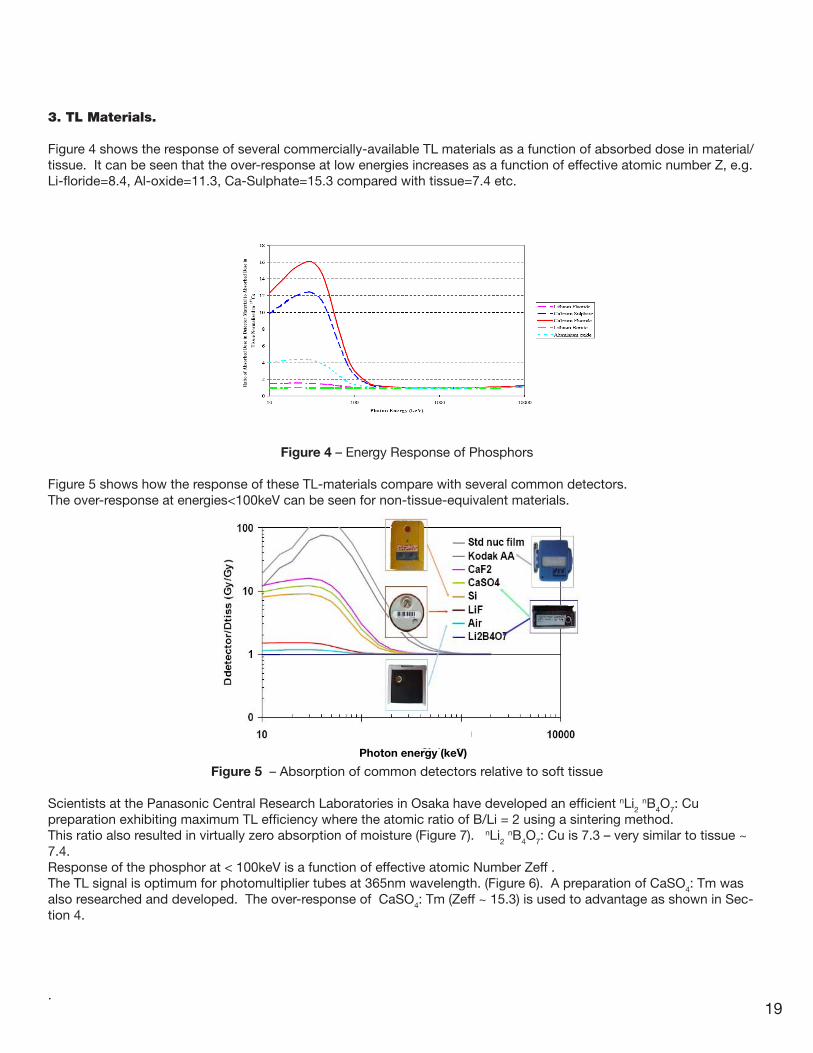
3. TL Materials.
Figure 4 shows the response of several commercially-available TL materials as a function of absorbed dose in material/tissue. It can be seen that the over-response at low energies increases as a function of effective atomic number Z, e.g. Li-floride=8.4, Al-oxide=11.3, Ca-Sulphate=15.3 compared with tissue=7.4 etc.
Figure 4 – Energy Response of Phosphors
Figure 5 shows how the response of these TL-materials compare with several common detectors. The over-response at energies<100keV can be seen for non-tissue-equivalent materials.
Figure 5 – Absorption of common detectors relative to soft tissue
Scientists at the Panasonic Central Research Laboratories in Osaka have developed an efficient nLi2 nB4O7: Cu
preparation exhibiting maximum TL efficiency where the atomic ratio of B/Li = 2 using a sintering method. This ratio also resulted in virtually zero absorption of moisture (Figure 7). nLi2
nB4O7: Cu is 7.3 – very similar to tissue ~ 7.4. Response of the phosphor at < 100keV is a function of effective atomic Number Zeff . The TL signal is optimum for photomultiplier tubes at 365nm wavelength. (Figure 6). A preparation of CaSO4: Tm was also researched and developed. The over-response of CaSO4: Tm (Zeff ~ 15.3) is used to advantage as shown in Sec-tion 4.
.
Photon energy (keV)

20
Figure 6 - Glowcurves of 0.03wt% Cu-activated lithium borate at various B/Li atomic ratios
Figure 7 - Change of phosphor weight due to moisture absorption in Cu-activated lithium borate phosphors with various B/Li atomic ratios.

21
4. Discrimination and Algorithm
Dosimeters with 2 or less elements are known as non-discriminating dosimeters. This means that (a) no informa-tion about energy is available and (b) non-tissue-equivalent phosphors cannot accurately report unknown irradiations <100keV.
The flat response of Li2B4O7:Cu means that, in its simplest form, the dosimeter/reader can be calibrated at a single-point irradiation in dose-equivalent units. The addition of CaSO4 :Tm under a combination of plastic and lead allows the do-simeter to be exploited for energy and angular information.
Figure 8 – Dosimeter Construction..
Panasonic and users have developed dose algorithms based on the dose response of the four elements E1, E2, E3 and E4 in various holders.
The algorithm uses the element response ratios E1/E2, E2/E3, E3/E4, E1/E4 and (E2-E4)/(E1-E4), allowing the users to calculate Hp(0.07), Hp(10), Hp(3) and also to identify particles and energies as a result of the algorithm.
Alternatively, the user can generate their own dose response algorithm particular to their own dosimeter/holder combina-tion. Because the UD-802A has built-in filters, simple plastic holders can be sourced and algorithms simply built.

22
Step 1 – The dosimeter/holder combination is irradiated with 137Cs to calibrate the TLD Reader to match the deep dose equivalent for Element 2 and for Element 3.
Step 2 – The dosimeter/holder combination is irradiated and read for several lower energies (figure 9)
Figure 9 – Chart of element responses as a function of radiation energy.
Step 3 – Calculate and plot the ratio of Element 3/Element 4 as a function of Element 2 (Figure 10)
Step 4 – Add trendline and curve fit to a minimum of two orders.
Figure 10 – Curve fit of 1/E2 as a function of Element ratios .
Finally, for any four-element dosimeter readout, the true deep-dose response can be calculated as a function of E2 * (0.0043x² - 0.084x + 1.4233) (example only).
The energy approximation can also be obtained from the same E3/E2 ratio.

23
5. Dosimeter Construction.
To eliminate human errors in handling at the dosimetry laboratory and wearing, Panasonic designed an element card that is permanently encapsulated. This has the following advantages:
a) The dosimeter is extremely robust inside and outside it’s wearing holder and can be mailed/handled securely.b) The dosimeters built-in filters eliminate most shielding variations experienced in the other forms using holders with metal shields.c) The dosimeter lends itself to automatic packing/wrapping or any form of simple plastic holder.
Finally, the dosimeter has a unilateral construction - front and back (Figure 11).
Figure 11 – Dosimeter construction
It should be noted that Element 1 (Li2B4O7:Cu) is attenuated by only 14 mg/cm2 plastic whilst the actual phosphor layer itself of ~90μm, rendering it almost ideal for superficial dose measurement.

24
6. General Characteristics
Response stability:Under normal operating conditions, the UD-802A dosimeter shows a very stable dose response for more than 1,000 cycles of exposure readings – ideal for correction factor application.
Reproducibility: Li2B4O7:Cu ± 5% CaSO4 :Tm ± 2.5%
Fading: <5%/year (corrected)
Angular dependence: The UD-802A will have some dependency on the construction of the holder, but for the standard Panasonic holder UD-874ATM at 0 – 60º irradiation to the following energies:75keV Element 2 : 1.0 to 1.10. Element 4 : 1.0 to 1.20 60Co Element 2 : 1.0 to 1.05 . Element 4 : 1.0 to 1.10 The high over-response at 60º to 75keV on Element 4 is a function of some secondary-electron activity of the Pb-filter and it used to advantage in algorithms to detect angular irregularities.
Detectable Dose: 0.01mSv with 95% confidence
Dose Confirmation: Four glowcurves per dosimeter – each glowcurve counts digitally sampled at 22msec intervals.
7.Readers
The optical heating system described in Section 1 has been installed in a variety of readers such as:
UD-716AGL Desktop readerUD-7900M Automatic reader
The most advanced TLD reader for large scale processing is the UD-7900M.
Figure 12 – UD-7900M Automatic TLD Reader.
Additionally, an automatic irradiator UD-794D based on the UD-7900M mechanics and utilizing a 74GBq source is available with a 500 dosimeter loading. A custom designed shield and shutter reduces the background radiation to levels generally acceptable to an office environment use. The user can program one irradiation across all dosimeters or store profiles for a dif-ferent irradiation for every dosimeter.

25
8. Manufacturing
The dosimeters are irradiated with a 137Cs source and the responses are calculated by comparing the irradiated value and read value from a TLD Reader standardized with reserved calibration TLDs. The dosimeters are ranked according to the response of each element (Q, R and S-codes) and then selected according to the standard deviation of each individ-ual element compared to the mean response for that same element (Q and R-codes) in order to unify their sensitivities. Only T-codes are not ranked but selected according to the response.
All Dosimeters have sequential seven-digit ID Codes specified by the user when ordered.
Panasonic dosimeters are delivered and stored in magazines holding 50 dosimeters at a time. The magazine slots are keyed for correct dosimeter insertion. The magazines are inserted into the TLD readers for processing.
Figure 13 –Dosimeter Magazines
9. References
[1] Yamamoto et al., Construction of a Composite Thin-Element TLD using an Optical Heating Method. Health Phys. Vol. 43, No. 3, pp 383-390. (1982)[2] Barnes, A., Heat Flux Sensors. Sensors Online (1999)[3] UD-7900M Operation Manual v1.9 (2002) [4] Bartlett D. Harmonisation and Dosimetric Quality Assurance (Eurodos 2005).[5] Yamamoto et al., A New Phosphor for TLD. Health Physics Vol.44, No.4 (1983)[6] Plato P. Users Manual for Panasonic TLD Reader