tagnite and keronite assessment on magnesium & aluminum · tagnite and keronite assessment on...
TRANSCRIPT

Tagnite and Keronite Assessment on Magnesium & Aluminum ASETSDefense 2014: Sustainable Surface Engineering for Aerospace and Defense - 19 NOVEMBER 2014

Report Documentation Page Form ApprovedOMB No. 0704-0188
Public reporting burden for the collection of information is estimated to average 1 hour per response, including the time for reviewing instructions, searching existing data sources, gathering andmaintaining the data needed, and completing and reviewing the collection of information. Send comments regarding this burden estimate or any other aspect of this collection of information,including suggestions for reducing this burden, to Washington Headquarters Services, Directorate for Information Operations and Reports, 1215 Jefferson Davis Highway, Suite 1204, ArlingtonVA 22202-4302. Respondents should be aware that notwithstanding any other provision of law, no person shall be subject to a penalty for failing to comply with a collection of information if itdoes not display a currently valid OMB control number.
1. REPORT DATE 19 NOV 2014 2. REPORT TYPE
3. DATES COVERED 00-00-2014 to 00-00-2014
4. TITLE AND SUBTITLE Tagnite and Keronite Assessment on Magnesium & Aluminum
5a. CONTRACT NUMBER
5b. GRANT NUMBER
5c. PROGRAM ELEMENT NUMBER
6. AUTHOR(S) 5d. PROJECT NUMBER
5e. TASK NUMBER
5f. WORK UNIT NUMBER
7. PERFORMING ORGANIZATION NAME(S) AND ADDRESS(ES) Battelle,505 King Avenie,Columbus ,OH,43201
8. PERFORMING ORGANIZATIONREPORT NUMBER
9. SPONSORING/MONITORING AGENCY NAME(S) AND ADDRESS(ES) 10. SPONSOR/MONITOR’S ACRONYM(S)
11. SPONSOR/MONITOR’S REPORT NUMBER(S)
12. DISTRIBUTION/AVAILABILITY STATEMENT Approved for public release; distribution unlimited
13. SUPPLEMENTARY NOTES ASETSDefense 2014: Sustainable Surface Engineering for Aerospace and Defense, 18-20 Nov 2014, FortMyer, VA.
14. ABSTRACT
15. SUBJECT TERMS
16. SECURITY CLASSIFICATION OF: 17. LIMITATION OF ABSTRACT Same as
Report (SAR)
18. NUMBEROF PAGES
53
19a. NAME OFRESPONSIBLE PERSON
a. REPORT unclassified
b. ABSTRACT unclassified
c. THIS PAGE unclassified
Standard Form 298 (Rev. 8-98) Prescribed by ANSI Std Z39-18
Project Team COTR – Tom Lorman (LCMC/WNVV) Project Manager - Jim Tankersley Technical Task Managers – John Stropki, Jill Gregory • Additional Stakeholders OO-ALC (Wayne Patterson 809 MXSS/MXDEC)
F-16, F-35, and F-22 Program Offices
Lockheed-Martin Aerospace
USAF Corrosion Prevention and Control Office (AFCPCO)
US Army AMRDEC

Objective and Goal • Objective: Conduct a Qualification Operational Test and
Evaluation (QOT&E) of the Tagnite® and Keronite® surface treatments as an alternative to current chromated conversion coatings (Dow 7) and anodizing treatments (Dow 17). The experimental coating systems will be compared to existing MIL-SPEC coating systems currently being applied to Mg and Al off-aircraft component parts at Hill AFB.
• Goal: Validate a non-chrome containing surface pretreatment/primer coating and powder coating system for use on magnesium and high strength cast and wrought aluminum parts.

Background – Technology Solution • NAVAIR has conditionally approved Tagnite® and Keronite®
treatments for all Mg alloys. • AFCEE funded Leidos (SAIC) to comparatively assess
Tagnite® and Keronite® on Mg alloys only: Literature review, experimental test plan, cost benefit analysis
Funding did not support fabrication or testing panels or parts at Hill AFB
• Air Force (LCMC/WNVV) funded Battelle to evaluate Tagnite® and Keronite® on Mg and Al alloys Battelle responsible for fabrication/coating all test panels, performing
B117, Adhesion, and strippability on Hill AFB (Leidos) panels
Battelle and Leidos will not duplicate efforts

Background – Tagnite® Coating • Hard anodized coating developed in the 1990’s • No heavy metals or chromates • Deposited as columnar and porous film • Electrolyte’s pH is 12.8 - 13.2 and operates below room
temperature (40° – 60° F) • 8 tank process line
Sand Cast Magnesium Gearbox For a Jet Engine

Background - Keronite® Coating • Initial Treatments: Clean parts with
alkaline degreaser (less stringent requirements). Etching not required.
• Processing Treatment: PEO uses different electrolytes and higher current densities to achieve microscopic plasma discharges for modifying oxide film (micro-arc fusing of oxide layers)
• Coating Growth: Typical oxide film thickness for Mg is 0.4 – 0.8 mils, and 1.0 – 1.5 mils for Al alloys
• Target Alloys: AZ31B Mg Alloy, as well as 6061-T6, 7075-T6 and 2024-T3 aluminum alloys

Technical Approach • Identify Mg and Al alloys and parts being conversion coated
and/or chromic acid anodized at Hill AFB. • Work with Hill AFB and Leidos to update draft Test Plan to
include several aluminum aerospace alloys. • Prepare and test panels and condemned off-aircraft parts w/
complex geometries. • Define compatibility, adhesion and corrosion resistance of
alternative surface treatments with powder coatings being investigated by Hill AFB.
• Develop a technology transition plan that identifies licensing options and costs, as well as equipment, facility and personnel investments.

The matrix of substrates and coatings provided comprehensive stackups that span baseline, chrome, and chrome-free combinations.
Substrate Surface Treatment
Sealer Primer Topcoat
• Al 2024 • Al 6061 • Al 7075 • Mg AZ31B
• Dow 17 • PreKote • Alodine 5900 • Keronite • Tagnite 8200
• Rockhard 576-450-002
• MIL-PRF-23377 (chrome)
• MIL-PRF-85285 • TCI Powder Coat

Visual of Keronite and Rockhard surface treatments
Battelle The Bui,-ln c:.so/Tnnoval-ion

Visual of Tagnite and Rockhard surface treatments
0
I!
Battelle The Bui,-ln c:.so/Tnnoval-ion

Dissimilar Metal Panels
Profile
Rear
Front
Cu Ni-Cu Alloy 400 303 SS

Mounting orientation of dissimilar metals panels created corrosive environment for exposed dissimilar metals
Keronite without/with Rockhard Tagnite without/with Rockhard |

Keronite Coated Aircraft Parts
C-130 Diffuser Housing (Cast Al) C-130 Gearbox Housing (AZ91C-T6 Mg)

Tagnite Coated Aircraft Part
C-130 Gearbox Housing (AZ91C-T6 Mg)
Battelle The Bui,-ln c:.so/Tnnoval-ion

SEM/EDS Results COATING SURFACE ANALYSIS

SEM/EDS Coating Surface Analysis Dow 17" Anodized Coating (SOOX Magnification) Substrate Film Thickness, j.lm Chemistry, wt % Comments
• Very porous
• Irregular
• Non-c : 2.9-4.2 unifo rm 0 : 19.5 - 19.6 • Globular F: 12.7 - 14.0 • Cracking
Na: 4.8 - 5.2 • 2-4 j..lm Mg AZ31B 5-30 Mg: 28.1 - 29.9 dense
AI: 0.4 - 0.6 coaling on P: 15.3 - 15.4 subst rate
Cr: 12.9 - 14.1 • Mg and cr•<> oxides provide corrosion prol eclion
Tagnite" Coating (SOOX Magnification) Substrate Film Thickness, j..lm Chemistry Comments
• Very porous
• Semi-c : 3.2 - 3.5 unifo rm
Subslrau~ 0: 24.6 - 26.6 • .5-1 ~-tm
F: 3.5 - 7.6 dense
Na: 0.4 Mg AZ31B 4-10 Mg: 48.5 -49.9
coat ing on
AI: 1.5 - 2.1 subsl rale
Si: 12.8 -14.9 • Th icker Mg
K: 0.5 -1.3 oxide wiLh AI oxides
• Si rrom electrolyte
Battelle The Bui,-ln c:.so/Tnnoval-ion

SEM/EDS Coating Surface Analysis Substrate Film Thickness, µm Chemistry CommentsMg AZ31B 7-15 C: 3.8-11.6 -Pourous
O: 24.2-24.8 -Semi-uniformF: 4.9-5.5 -1-2µm dense coating on substrateNa: 0.5 -Rockhard fills in pore and is non-detectableMg: 43.8-49.3Al: 1.1-1.6Si: 12.4-14.1K: 0.7-0.8
Substrate Film Thickness, µm Chemistry CommentsMg AZ31B 10-15 C: 2.9-4.9 -Very pourous
O: 26.0-27.0 -Irregular, globularF: 0.7-1.3 -1-2µm dense coating on substrateNa: 1.2-1.6 -Mg and Al oxides provide corrosion protectionMg: 47.3-52.4Al: 11.1-12.8P: 3.2-5.5
Keronite® Coating (2000X Magnification)
Substrate

SEM/EDS Coating Surface Analysis Substrate Film Thickness, µm Chemistry Comments
Al 2024 1-3 C: 10.6-26.7 -PourousO: 29.1-31.5 -Semi-uniform, globularMg: 0.7-1.3 -0.3-0.5 µm dense coating on substrateAl: 14.4-47.5 -Al oxides provide corrosion protectionP: 8.9-27.6Si: 0.7-1.6
Keronite® + Rockhard® Coating (2000X Magnification)
Substrate
Substrate Film Thickness, µm Chemistry CommentsMgAZ31B 10-15 C: 3.5-7.9 -Very pourous
O: 25.1-25.9 -CrackingF: 0.8-1.3 -Semi-uniform, globularNa: 1.3-1.5 -1-2 µm dense coating on substrateMg: 43.7-49.5 -Mg and Al oxides provide corrosion protectionAl: 11.8-17.7P: 3.0-4.6

Aluminum and Magnesium Panels 12-MONTH OUTDOOR EXPOSURE RESULTS

All tested conversion coatings, with the exception of Tagnite and Keronite surface treatments, required a chromated primer with the powder coat.
The Bui,-ln c:.so/Tnnoval-ion

Keronite with powder coat was the best performing non-chrome stackup for aluminum panels
Battelle The Bui,-ln c:.so/Tnnoval-ion

Tagnite with Rockhard and powder coat was the best performing non-chrome stackup for Mg AZ31B panels
Battelle The Bui,-ln c:.so/Tnnoval-ion

SEM analysis of scribe cross section showed complete powder coat adhesion loss with Alodine 5900, and very minimal with Keronite and Tagnite.
Scribe area
Cross-section AZ31B Mg panel treated with Alodine T5900 and
powder coat
Cross-section AZ31B Mg panel treated with Keronite and powder
coat
Cross-section AZ31B Mg panel treated with Tagnite, Rockhard,
and powder coat

Dissimilar Metal Panels 12-MONTH OUTDOOR EXPOSURE RESULTS

Keronite-only panels showed moderate corrosion at the interface and exposed substrate from maskant removal
Battelle The Bui,-ln c:.so/Tnnoval-ion
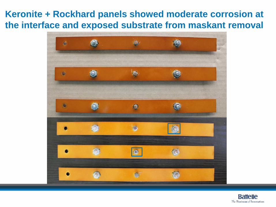
Keronite + Rockhard panels showed moderate corrosion at the interface and exposed substrate from maskant removal
~ . , . ~
\ ' ''~Jl'' : ~~' ~:~)' , -
..
Battelle The Bui,-ln c:.so/Tnnoval-ion

Tagnite-only dissimilar metals panels exhibited corrosion around dissimilar metal interfaces, especially the copper fitting
Battelle The Bui,-ln c:.so/Tnnoval-ion

Tagnite + Rockhard dissimilar metals panels exhibited corrosion around dissimilar metal interfaces, with significant fading of the Rockhard coating.
Battelle The Bui,-ln c:.so/Tnnoval-ion
ASTM B117 Salt Fog LABORATORY TEST RESULTS

ASTM B117 Salt Fog Testing Panel Placement in Chamber
Cycle Time RH Temperature
Salt Fog Simple Solution 24 hours 100% 35°C

Several baseline panel sets exhibited severe corrosion and were removed from the chamber
Mg Alloy Panel after 48 hrs. Mg+PreKote+Primer+Topcoat
Battelle The Bui,-ln c:.so/Tnnoval-ion

Severe corrosion and coating failure noted on magnesium panel with Alodine 5900 and powder coat after 700 hrs, while no corrosion noted on Al 2024 stackup after 1,500 hrs
Al2024 + Alodine 5900 + Powder Coat Mg AZ31B + Alodine 5900 + Powder Coat

All chrome-free magnesium stackups failed the ASTM B117 2,000 hour salt fog test
• Tagnite non-chrome stackup (Tag+R+PC): all magnesium panels failed at the scribe line and edges by 2,000 hours.
• Keronite non-chrome stackup (K+PC): all aluminum panels passed at 2,000 hours, while all magnesium panels failed.
Aluminum Magnesium

ASTM B117 Salt Fog Test Summary • Extensive corrosion and coating disbondment for a majority of the AZ31B Mg test
panels treated with Dow 17, PreKote, and Alodine T5900 after ~700 hours of exposure
• All Al alloy test panels treated with the Dow 17, PreKote and Alodine T5900 passed the 2,000 hour test with only minimal coating blisters and localized corrosion along the edges and hole cut.
• The majority of surface area on all AZ31B Mg panels treated with Tagnite and Keronite were in fair condition following 2,000 hours. Localized corrosion and coating disbondment was confined to the edge, scribe and hole cut surfaces.
• All aluminum alloy panels treated with Tagnite and Keronite had only minimal scribe corrosion following 2,000 hours.
• The Rockhard coating did appear to reduce scribe corrosion for the Keronite treated panels.

ASTM D3359 Adhesive Testing LABORATORY TEST RESULTS

ASTM D3359 Adhesion Tests
• Failures:
Al 2024/6061/7075 and Mg, Keronite, Rockhard, Primer, Topcoat
Mg, Tagnite, Rockhard, Primer, Topcoat
Al 2024/6061 and Mg, PreKote, Primer, Topcoat
Mg, PreKote, Powder coat
Mg, Primer, Powder coat
Mg, Dow 17
Al 2021/6061 and Mg, Alodine 5900, Primer, Powder coat
Mg, Alodine 5900, Primer, Topcoat
Mg, Alodine 5900, Primer, Powder coat
Passed: All substrates with Keronite/Tagnite, Rockhard, and powder coat

Type II Dry Media Coating Removal LABORATORY TEST RESULTS

Type II Dry Media Coating Removal
• Specifications
Type II Urea dry media, 3/8” nozzle, 10” standoff, 80 degree angle, & 25 psi nozzle pressure
Acceptable coating removal rate determined to be between 0.3-0.5 ft2/min
• Results
Testing confirmed the Keronite and Tagnite surface treatments cannot be removed with Type II media without damaging the Al or Mg test panels.
Selective removal of organic coatings possible due to porous and irregular surface morphology for all Mg and Al panels coated with the Tagnite and Keronite surface treatments (with and without Rockhard).
− Powder coating removal rates were very low (0.06 ft2/min)
− MIL-SPEC primer + topcoat rates were higher (0.33 ft2/min)

Keronite implementation for aluminum components at Hill AFB BUSINESS CASE ANALYSIS

Business Case Analysis Overview
• Battelle assessed the business case for Hill AFB to transition to the Keronite process for aluminum parts Supplements Leidos BCA conducted under separate Task Order for
Keronite and Tagnite for magnesium parts
• Battelle baselined paint operations for two aluminum component process lines at Hill AFB Propulsion Directorate (Bldg 238) – Alodine T5900 conversion coating
Landing Gear Shop (Bldg 507) - Type II Sulfuric acid anodizing
• The following slides convey the baseline assessment and the advantages and disadvantages of transitioning to the Keronite technology.

Business Case Analysis Summary of Results
• Keronite with powder coat offers the only chrome-free coating system for aluminum alloys with comparable performance to the baseline chrome-containing stackup. Time and cost savings are associated with the elimination of the chromated primer.
• Keronite electricity usage is an order of magnitude higher than the anodizing line or the Alodine process. The electricity usage is dependent on component substrate, surface area, and desired coating thickness.
• Keronite electrolyte consumption is significantly higher than the anodizing line or the Alodine process. Both baseline processes added approximately one 55-gallon drum of material to the bath per year.
• The electrolyte consumption is based on component substrate, surface area, and desired coating thickness; however, the range for aluminum is anywhere from 0.02-0.22 liters/ft2.

Business Case Analysis Summary of Results – Cont’d
• The Keronite system is based on a lease-license agreement where the base would rent the equipment from Keronite for a period of at least 5-years. This contract is negotiable.
• Keronite also offers subcontracting to their Greenwood, Indian facility.
• The results of Keronite process investment indicate an increase in annual costs by as much as $100,000.00, in addition to approximately $54,000.00 in one-time start-up costs.
• This could be partially offset by the benefits of reduced hazardous material exposure, treatment costs at the IWTP, reduction of time/costs to apply primer, and nominally-reduced permitting requirements.

Contact Information Tom Lorman (USAF LCMC/WNVV) 937.255.3530 [email protected]
Jim Tankersley (Battelle) 937.258.6724 [email protected]
John Stropki (Battelle) 614.424.5414 [email protected]
Jill Gregory 614.424.5103 [email protected]
Back-up Slides

Business Case Analysis Baseline Processes – Propulsion Directorate
CEE-BEE 300 FLM Degreaser, 25 minutes, 150F, ultrasonic tank
CEE-BEE 300 FLM Degreaser, 25 minutes, 150F, ultrasonic tank
DI water + Nortex 3025 (0.5% conc.)1-2 minutes, 150F
DI water + Nortex 3025 (0.5% conc.)1-2 minutes, 150F
P-2 P-3 P-4P-1Part enter
in Basket
Alodine T5900 (Pretreatment Line)7-10 minutes, Ambient
P-5
DI water 1-2 minutes, 150F
P-6P-7 Air Dryer
30 mins160F
Chrome Primer
Low Temperature Powder Coat
P-8 P-9
• Analyst data for the 309th maintenance wing suggested 15,387 aluminum parts were processed in a 12-month period with about 2.5% (±1%) scrapped for corrosion related issues.
• Topcoat and primer are always removed, however Alodine coating may remain prior to recoating
• Total process time ~1.5 hrs + 1-3 days for prime + powder coat

Business Case Analysis Baseline Processes – Landing Gear
• Primary parts are 2000 series aluminum wheels and struts • FPI/NDI techniques used do not require complete removal of anodize
coating. • Parts with >10% bare metal undergo sulfuric acid anodize • Total process time ~1 hr + 1 day primer/paint
Optional, Anodize Coating Strip Tank
Alkaline CleanerMacDermid Isoprep 44,
1-5 minutes, RT
DI Water Dip,20 secs, RT
Optional, EtchMacDermid Metex 138S,
1-2 mins, 140F
P-2 P-3 P-4
Deoxidizer,MacDermid Isoprep 184,
1-2 mins, RT
DI water dip,20 secs, RT
P-5
DI Water Dip,20 secs, RT
DI Water Dip,20 sec, RT
Type II Sulfuric Acid Anodize Tank23-29 oz/gal Sulfuric Acid,
~25 minutes @ 18V, 62-70F
DI Water Dip,20 secs, RT
DI Water Dip,20 secs, RT
Sodium Dichromate Seal,15 mins, 210F
DI Water Dip,20 secs, RT
Hot DI Water Dip,20 secs 150F
P-6
P-7 P-8 P-9 P-10 P-11 P-12
P-13 P-14
P-1Part IN
Air Dryer160F
Non-chrome Primer
Wet Topcoat
MIL-PRF-85285
IR Dryer IR DryerPart OUT
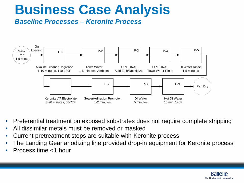
Business Case Analysis Baseline Processes – Keronite Process
• Preferential treatment on exposed substrates does not require complete stripping • All dissimilar metals must be removed or masked • Current pretreatment steps are suitable with Keronite process • The Landing Gear anodizing line provided drop-in equipment for Keronite process • Process time <1 hour
Alkaline Cleaner/Degrease1-10 minutes, 110-130F
Town Water1-5 minutes, Ambient
P-2P-1
Keronite A7 Electrolyte3-20 minutes, 60-77F
Sealer/Adhesion Promotor1-2 minutes
DI Water 5 minutes
P-8
Mask Part
1-5 mins
Hot DI Water10 min, 140F
P-9
Jig Loading
DI Water Rinse,1-5 minutes
P-7Part Dry
OPTIONAL Acid Etch/Deoxidizer
OPTIONALTown Water Rinse
P-4 P-5P-3

Implementation advantages of the Keronite process for aluminum components include selective coating removal and a chrome-free stackup.
Process Changes from Program Depot Maintenance (PDM) Cycle 1 through Subsequent PDM Cycles
Baseline CPC Operations
PDM Cycle 1 – Keronite Application
Potential Cost Increase/Reduction
Subsequent PDM Cycles
Potential Cost Increase/Reduction
Depainting Strip to bare metal
Increase Partial depaint (only powder coat and sealant removed)
Reduction
Inspect & Repair No Change Not Applicable No Change Not Applicable
Painting Adds Keronite + Sealant; Removes Chrome Primer and/or Dichromate Sealant
Increase Eliminates Keronite reapplication, only need provide touchup conversion coating & sealer.
Reduction

The Keronite process energy is a significant increase in comparison to the Alodine T5900 process and the Type II sulfuric acid anodizing process.
C-130 cast aluminum diffuser housing with ~7.5 micron coating
Substrate Energy Consumption (kWh) Electricity Cost per part (5.68₵/kWh1)
Keronite 22 $ 1.25
Alodine T5900 0 $ -
Type II Sulfuric Acid Anodize2 0.5 $ 0.03 1 April 2014 average cost per kilowatt-hour for industrial entities in Utah. (U.S. EIA, 2014) 2 Calculated using reported values of power supply set to 18V for 25 minutes and an average value of 13.5A/ft2. Validated estimation with typical energy consumptions reported from sulfuric acid anodizing methods.
The required energy for the Keronite process is nearly 44 times the electricity consumption for the current anodizing process.

Important process variables (i.e. process time, electrolyte consumption, and energy usage) can be determined for each part.
Parameter Coating, 10 µm Coating, 5 µm Pre-treatment (<5 µm)
Alloy cast 2xxx
7xxx
5xxx
6xxx
cast 2xxx
7xxx
5xxx
6xxx
cast 2xxx
7xxx
5xxx
6xxx
Max load (ft2) 11 22 22 11 22 22 11 22 22
Process Time (min) 20 12.5 10 12 7.5 6 6 3.75 3
Energy (kWh/ft2) 4.65 1.85 1.4 2.79 1.11 0.84 1.39 0.56 0.42
Electrolyte (L/ft2) 0.22 0.09 0.07 0.13 0.05 0.04 0.07 0.03 0.02
ft2/shift 191 567 676 293 837 976 490 1300 1460
ft2/month 11k 34k 41k 18k 50k 59k 29k 78k 88k
For example, the landing gear shop wheels are 2000 series aluminum which would require ~2.5 times less energy per square foot to coat than cast aluminum.
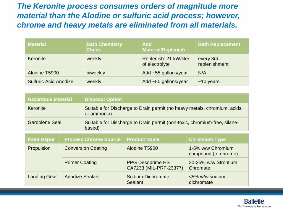
The Keronite process consumes orders of magnitude more material than the Alodine or sulfuric acid process; however, chrome and heavy metals are eliminated from all materials.
Material Bath Chemistry Check
Add Material/Replenish
Bath Replacement
Keronite weekly Replenish: 21 kW/liter of electrolyte
every 3rd replenishment
Alodine T5900 biweekly Add ~55 gallons/year N/A
Sulfuric Acid Anodize weekly Add ~50 gallons/year ~10 years
Hazardous Material Disposal Option
Keronite Suitable for Discharge to Drain permit (no heavy metals, chromium, acids, or ammonia)
Gardolene Seal Suitable for Discharge to Drain permit (non-toxic, chromium-free, silane-based)
Paint Depot Process Chrome Source Product Name Chromium Type
Propulsion Conversion Coating Alodine T5900 1-5% w/w Chromium compound (tri-chrome)
Primer Coating PPG Desoprime HS CA7233 (MIL-PRF-23377)
20-25% w/w Strontium Chromate
Landing Gear Anodize Sealant Sodium Dichromate Sealant
<5% w/w sodium dichromate

The Keronite process technology licensing costs incorporate equipment leasing/usage, maintenance, installation support, training, and transportation.
Specifications
Lease Term (years) 5
Keronite Processing Unit Size (WxDxH) 10.3'x4.7'x5.5'
Keronite PSU Size (WxDxH) 11'x3'x7'
Tank size (liters) 2000
Equipment Costs
Equipment Lease (1st term) $ 256,500.00
Equipment Lease (2nd term) $ 128,250.00
Equipment Lease (single year) $ 34,200.00
Maintenance (single year, required) $ 8,550.00
Startup Costs
Packaging/Shipping $ 11,970.00
Installation support, commissioning, training1 $ 42,750.00
Usage Costs
Equipment usage charge ($/kWh) $ 0.10
Electrolyte cost ($/liter) $ 4.00

The estimated yearly cost of licensing and using the Keronite technology is roughly $100,000.
Summary of Estimated Costs (10 year rental)
Yearly Equipment Cost (10yr plan) $ 38,475.00
Yearly Maintenance Visit Costs $ 8,550.00
Estimated Yearly Equipment Usage Charge2 $ 14,040.00
Estimated Yearly Electrolyte Cost3 $ 42,832.00
Estimated Yearly Cost4 $ 103,897.00
One time installation cost $ 54,720.00 1 2-days training for 3 employees, 5 days tech assistance during commissioning 2 Assumes 650 wheels/month, 5 µm coating, 18 kWh/part 3 Assumes complete tank refill twice per year and electrolyte consumption for 5 µm coated wheel 4 Assumes an exchange rate of 1 £ = 1.71 USD