tai lieu canh tay robot
TRANSCRIPT

7/27/2019 Tai Lieu Canh Tay Robot
http://slidepdf.com/reader/full/tai-lieu-canh-tay-robot 1/7
Servo Controller Instructions for Use PowerSupply
The servo controller needs two power supplies: servo power supply and chip power supply.
Servo power supply (+): VS (left of the blue connecting terminal at Position 3 in the figure)
Servo power supply (‐): GND (middle of the blue connecting terminal at Position 3 in the figure)
Servo power supply’s parameters depend on the parameters of the attached servo. For example, if the TR213
servo has a power supply of 4.8‐7.2V, the servo power supply can use the power source of 4.8‐7.2V.
Chip power supply (+): VSS (right of the blue connecting terminal at Position 3 in the figure)
Chip power supply (‐): GND (middle of the blue connecting terminal at Position 3 in the figure)
There is a VSS requirement of 6.5‐12V. If the chip power is input through the VSS port, the power supply has to
range from 6.5 to 12V.
Notes:
1. The USB port at Position 2 in the figure can supply power to the chip. So it is adequate to choose the USB
port or alternatively the VSS port.
2. Position 1 in the figure can supply power to the chip as well, marked 5V and GND, where 5V is the anode and
GND is the cathode. The power supply has to be 5V.
3. Positions 1, 2 and 3 can supply power to the chip. It is adequate to choose any of them.
4. The green LED light at Position 4 in the figure is the chip power indicator. If the green light is on, it indicates
the chip power works correctly; if the light is off, it indicates the chip power malfunctions.
5. The green LED light at Position 5 in the figure is the servo power indicator. If the green light is on, it indicates
the servo power works correctly; if the light is off, it indicates the servo power malfunctions.
It is necessary for both green LED lights to be on to control the servo.
7/27/2019 Tai Lieu Canh Tay Robot
http://slidepdf.com/reader/full/tai-lieu-canh-tay-robot 2/7
InstalltheDriver
The driver is available at http://www.torobot.com/down/usc_driver.exe (case‐sensitive)
Directly double click on USC_driver.exe; click on Next and the driver will be installed automatically.
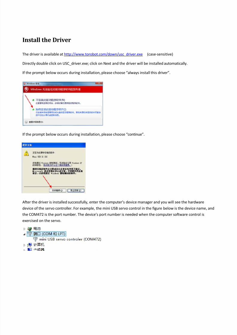
If the prompt below occurs during installation, please choose “always install this driver”.
If the prompt below occurs during installation, please choose “continue”.
After the driver is installed successfully, enter the computer’s device manager and you will see the hardware
device of the servo controller. For example, the mini USB servo control in the figure below is the device name, and
the COM472 is the port number. The device’s port number is needed when the computer software control is
exercised on the servo.
7/27/2019 Tai Lieu Canh Tay Robot
http://slidepdf.com/reader/full/tai-lieu-canh-tay-robot 3/7
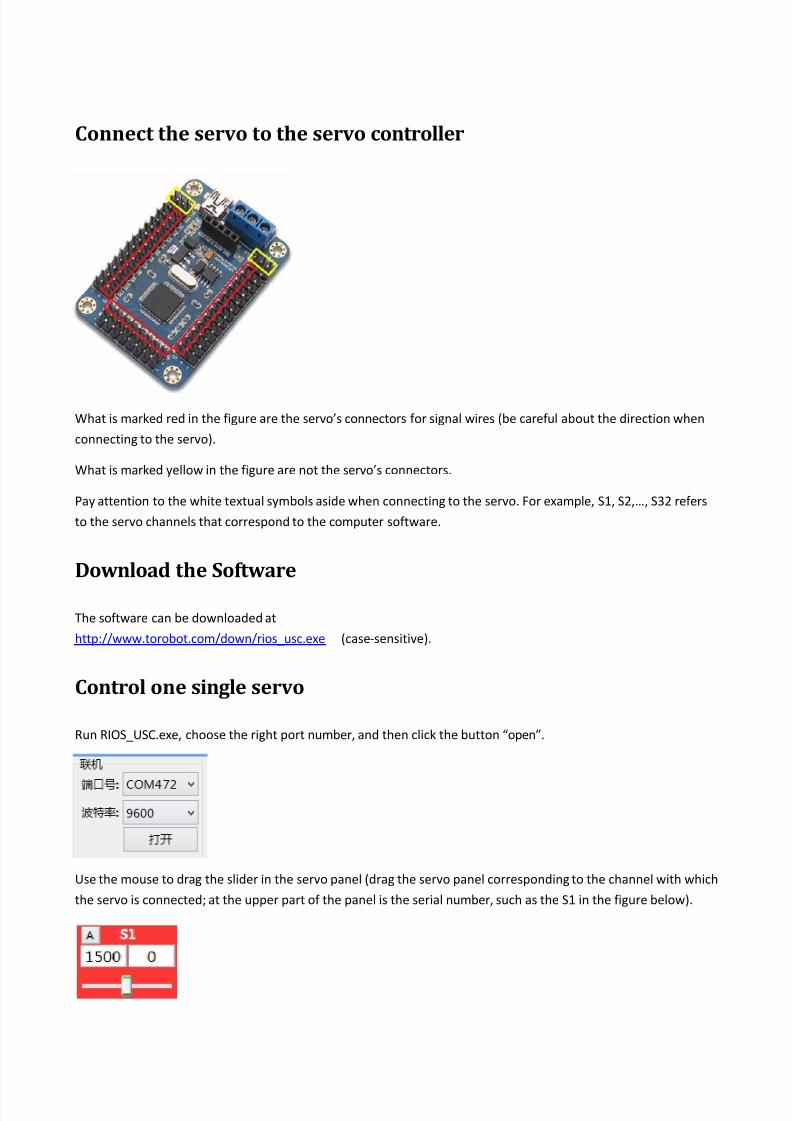
Connect theservototheservocontroller
What is marked red in the figure are the servo’s connectors for signal wires (be careful about the direction when
connecting to the servo).
What is marked yellow in the figure are not the servo’s connectors.
Pay attention to the white textual symbols aside when connecting to the servo. For example, S1, S2,…, S32 refers
to the servo channels that correspond to the computer software.
DownloadtheSoftware
The software can be downloaded at
http://www.torobot.com/down/rios_usc.exe (case‐sensitive).
Controlonesingleservo
Run RIOS_USC.exe, choose the right port number, and then click the button “open”.
Use the mouse to drag the slider in the servo panel (drag the servo panel corresponding to the channel with which
the servo is connected; at the upper part of the panel is the serial number, such as the S1 in the figure below).

7/27/2019 Tai Lieu Canh Tay Robot
http://slidepdf.com/reader/full/tai-lieu-canh-tay-robot 4/7
ControlMultipleServosSimultaneously
After multiple servos are controlled in sequence by following the steps above, set the time (e.g. in the figure below,
the setting, referred to as the rotary speed, is 1000ms; it has to fall in the range 100‐9999; the higher the value,
the slower the speed). Then click on the button “add” at the lower part of the software. The software will produce
a command at the lower part of the software which can exercise simultaneous control over all the servos that are
controlled earlier (if 10 servos are controlled earlier, the command can control these 10 servos simultaneously).
Downloadthe ActionGroup
If several or dozens of commands are produced by following the steps above, you can click on the button “run” at
the right of the software to test these commands.
If the test result is acceptable, you can click on the button “download” at the right of the software to download
the action group.
On completion of the download, the software will prompt “download is complete! No.=1”, where the number
refers to the serial number of this action group.
Afterwards, all commands in the group can be executed by executing the action group.
7/27/2019 Tai Lieu Canh Tay Robot
http://slidepdf.com/reader/full/tai-lieu-canh-tay-robot 5/7
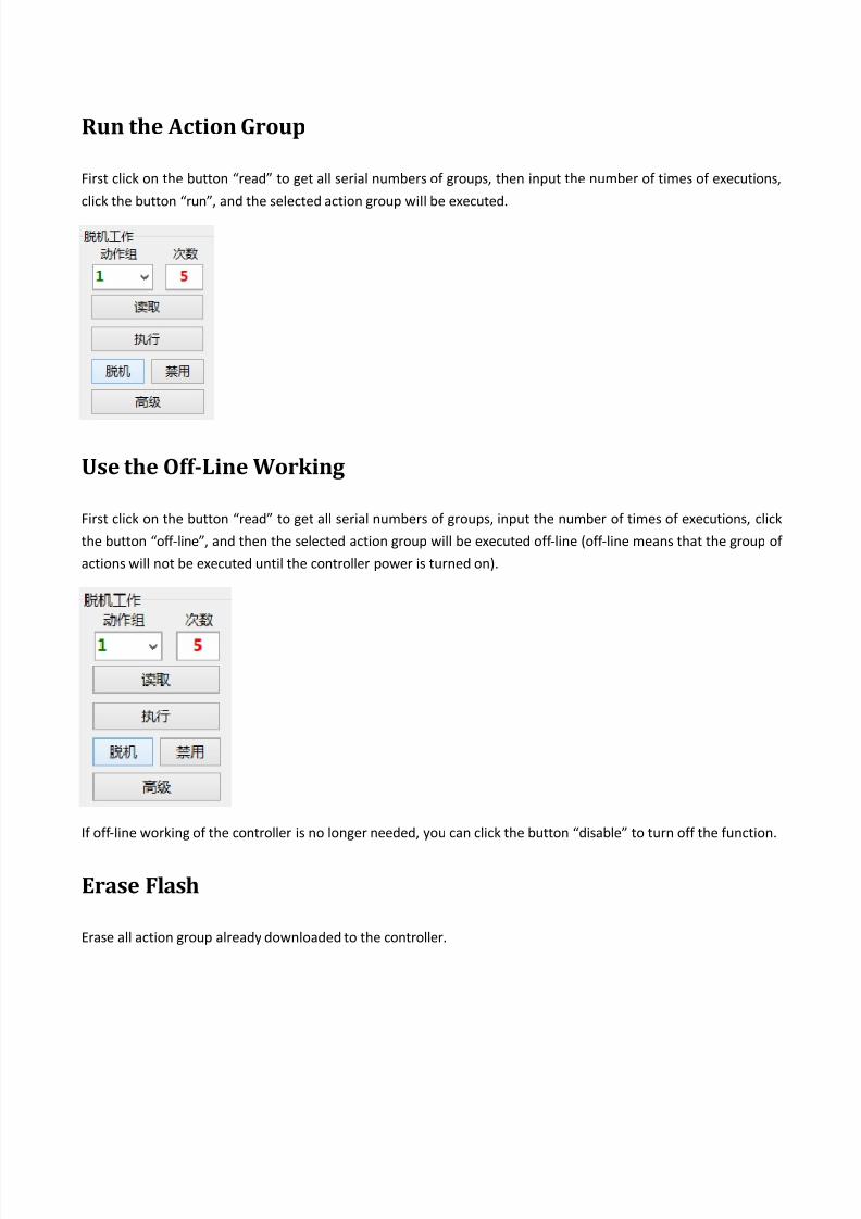
Runthe ActionGroup
First click on the button “read” to get all serial numbers of groups, then input the number of times of executions,
click the button “run”, and the selected action group will be executed.
UsetheOff ‐LineWorking
First click on the button “read” to get all serial numbers of groups, input the number of times of executions, click
the button “off ‐line”, and then the selected action group will be executed off ‐line (off ‐line means that the group of
actions will not be executed until the controller power is turned on).
If off ‐line working of the controller is no longer needed, you can click the button “disable” to turn off the function.
EraseFlash
Erase all action group already downloaded to the controller.

7/27/2019 Tai Lieu Canh Tay Robot
http://slidepdf.com/reader/full/tai-lieu-canh-tay-robot 6/7
Secondary development The
servo
controller
is
a slave
device,
meaning
that
it
can
either
accept
commands
or
execute
preset
commands.
It
cannot think at all.
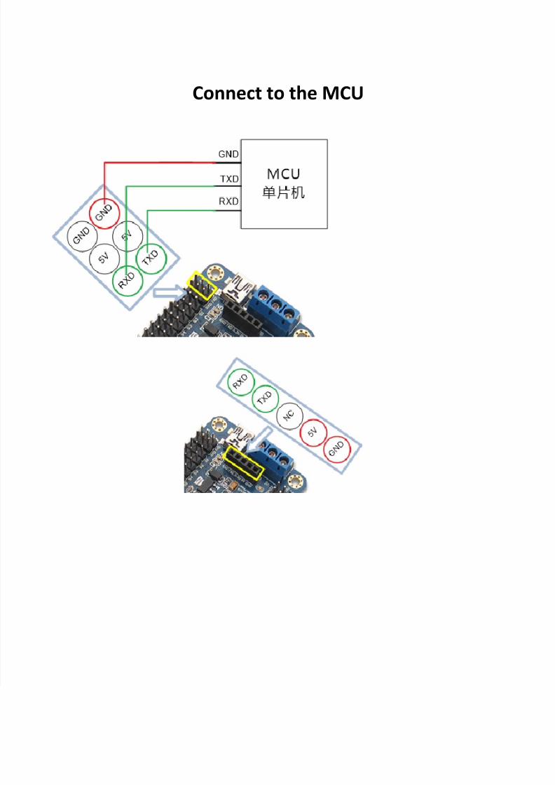
Communication protocol: serial communication (TTL level), baud rate 9600, no check bit, 8 data bits, 1 stop bit
To control the servo through the servo controller, users can self ‐develop computer software or use the MCU to
send commands to the servo controller.
Command format: Name Command Description
Control one single
servo
#1P1500T100\r\n
Data
1
refers
to
the
servo’s
channel
Data 1500 refers to the servo’ location, in the range
500‐2500
Data 100 refers to the time of execution and
represents the speed, in the range 100‐9999
Control multiple
servos
#1P600#2P900#8P2500T100\r\n
Data 1, 2, and 8 refer to the servo’s channels
Data 600, 900, and 2500 refer to the locations of the
servos that correspond to three channels
Data 100 refers to the time of execution and
represents the speed of three servos. Regardless of
the number
of
servos,
there
is
only
one
time,
or
one
T.
The command is executed at the same time; that is,
all servos operate simultaneously.
Execute one single
action group
#1GC2\r\n
Data 1 refers to the serial number of the action
group
Data 2 refers to the number of cycles
Execute multiple
action groups #1G#3G#1GC2\r\n
Execute the first, third and first action group,The
number of cycles is 2.
One
particular
group
of
action
can
appear
repeatedly.
There can be only one number of cycles or C.
The command is executed in sequence; that is, the
action groups are executed in sequence.
All commands above contain \r\n. It is the end mark of the command and is mandatory.
All commands are no spaces.
\r\n represents two characters of carrier return and linefeed, and are the hexadecimal 0x0D and 0x0A, or Chr(13)
and
Chr(10).
7/27/2019 Tai Lieu Canh Tay Robot
http://slidepdf.com/reader/full/tai-lieu-canh-tay-robot 7/7
Connect to the MCU