taxonomy and survey of rfid anti-collision protocols and survey of rfid anti-collision protocols...
TRANSCRIPT

Short survey
Taxonomy and survey of RFID anti-collision protocols
Dong-Her Shih a, Po-Ling Sun a, David C. Yen b,*, Shi-Ming Huang c
a Department of Information Management, National Yunlin University of Science and Technology, 123, Section 3,
University Road, Douliu, Yunlin, Taiwan, ROCb Raymond E. Glos Professor, Department of DSC and MIS, Miami University Oxford, OH 45056, USA
c Department of Accounting and Information Technology, National Chung Cheng University, No. 168 University Road,
Ming-Hsiung, Chia-Yi 62102, Taiwan, ROC
Received 1 December 2004; received in revised form 14 December 2005; accepted 18 December 2005Available online 18 January 2006
Abstract
Due to the limitless possibilities and low cost, Radio Frequency Identification (RFID) systems are used in a variety of applications touniquely identify physical objects. The operation of RFID systems often involves a situation in which numerous tags are present in theinterrogation zone of a single reader at the same time. The tags can collide and cancel each other out, leading to retransmission of tag IDsthat results in wastage of bandwidth and an increase in the total delay. Besides, readers physically located near one another may interferewith one another’s operation. Such reader collision must be minimized to ensure the current operation of the RFID system. The mainfocus of this paper is to survey the collision resolution protocols for multi-access communication and the algorithms that calculate howto minimize reader-to-reader interference. A comparative view of surveyed protocol was concluded for the collision problem in RFIDsystems.� 2006 Elsevier B.V. All rights reserved.
Keywords: RFID tag; Mobile communication; Tag collision; Reader collision; Anti-collision
1. Introduction
Ubiquitous tagging is a paradigm where everythingrelated has a unique tag associated with it. Picture the sce-nario that every object in the world can be uniquely identi-fiable with some form of electronic tags. This scenariowould create tremendous benefits in terms of trackingand identifying an object and making ubiquitous identifica-tion possible. As ubiquitous identification systems havebecome commonplace in access control and security appli-cations areas. Radio Frequency Identification (RFID) sys-tems are increasingly being used as the automatedidentification system for these applications. The first tradi-tional technology to be replaced by RFID is the bar codesystem – RFID can do everything bar codes can and much
more [1]. Optical barcodes suffer from several drawbacks.First, human intervention is required to scan a barcode.Objects must be physically manipulated to align barcodeswith scanners. Anyone who has shopped in market haslikely witnessed a cashier struggling to scan an item. Sec-ond, the readability of barcodes could be affected by dirt,moisture, abrasion, or packaging contours. Third, the abil-ity of storing data on barcode is very low. Fourth, retailersalso often affix barcodes, which are unnecessary for themon top of packaging of goods. Finally, the barcodes is eas-ily counterfeited. Among others, these issues limit the per-formance of optical barcode based on auto-ID systems.Today, over 5 billion bar codes are scanned daily world-wide [2,3] creating just one operation which RFID technol-ogy is predicted to take over. The actual idea of RFID hasbeen around since 1960 [4,5].
RFID supporters claim to see an integration of RFID inall businesses. In the world of RFID, Wal-Mart [6] is cur-rently the strongest advocate in promoting this new way to
0140-3664/$ - see front matter � 2006 Elsevier B.V. All rights reserved.
doi:10.1016/j.comcom.2005.12.011
* Corresponding author. Tel.: +1 513 529 4826; fax: +1 513 529 9689.E-mail addresses: [email protected] (D.-H. Shih), yendc@
muohio.edu (D.C. Yen), [email protected] (S.-M. Huang).
www.elsevier.com/locate/comcom
Computer Communications 29 (2006) 2150–2166

identify everything that can be marked with a RFID tag.Wal-Mart encourages its suppliers to adopt the technologyby 2005, at the latest, for identification at case level [7].Main competitors to Wal-Mart – e.g., Tesco and Metrogroup – follow closely behind, and cooperate to a certainextent in evaluating and implementing RFID at trial sites.The Metro Group operates ‘‘next-generation’’ supermarketin Rheinberg, Germany, with RFID implemented, wherebenefits of the technology have been seen [2]. There are stillmany other RFID applications. For instance, proximitycards, theft-detection tags, small dashboard devices forautomating toll payments [8], cash like Euro [3], and evencattle herding [9].
RFID systems are composed of three main componentsas shown in Fig. 1 [10]:
• One or more RFID tags, also known as transponders(transmitter/responder), are attached to the objects tocount or identify. Tags could be either active or passive.Active tags are those that are partly or fully batterypowered, have the capability to communicate with othertags, and can initiate a dialogue of their own with thetag reader. Passive tags, on the other hand, do not needany internal power source but are powered up by the tagreader. Tags consist mainly of a microchip and coiledantenna, with the main purpose of storing data.
• A reader or transceiver (transmitter/receiver) made upof an RF module and control unit. Its main functionsare to activate the tags, structure the communicationsequence with the tag, and transfer data between theapplication software and a tag.
• A Data Processing Subsystem, which can be an applica-tion or database, depending on the application.
The application software initiates all readers and tagsactivities. RFID provides a quick, flexible, and reliableway to electronically detect, track and control a varietyof items [11]. RFID systems use radio transmissions tosend energy to a RFID tag while the tag emits a uniqueidentification code back to a data collection reader linkedto an information management system. The data collectedfrom the tag can then be sent either directly to a host com-puter, or stored in a portable reader and up-loaded later toa computer [12]. The reader’s ability of processing a great
quantity of tags simultaneously for data collecting is note-worthy. If multiple tags are to be identified simultaneously,messages from tags can collide and cancel each other out atthe reader. This situation will lead to retransmission of tagIDs, which results in wastage of bandwidth and increasesthe total delay in identifying all the objects. Hence, anti-collision algorithms need to be devised between the tagsand reader to minimize collisions. If RFID systems canoffer features such as anti-collision and high-speed detec-tion combined with 100% data accuracy, then it can enableefficient usage in practically every application. Therefore,the natural problem is: what protocol should the readerand the tags use so that the ID of each tag can be commu-nicated to the reader as quickly and reliably as possible?Without any coordination between the reader and the tags,the responses from the tags to the reader can collide caus-ing the IDs of the tags to become illegible to the reader.Therefore, the RFID collision problems could be summa-rized and classified into the tags identification problem[13–18] and readers collision problem [19–22].
The tags identification problem is associated with howto efficiently develop an anti-collision protocol in RFIDtags. It can be defined as to identify multiple objects reli-ably without significant delay by utilizing minimal trans-mission power and computation. Collision-resolutionprotocols that address this problem cannot be directlyapplied to the tag identification problem due to variousconstraints [14]. In multi-access protocols, the main factorsfor performance evaluation include throughputs, packetdelay, and stability. However, in RFID arbitration, totaltime to identify all objects and the power consumed by tagsare more relevant. Abraham [23] claimed minimal delay,power consumption, reliability & completeness, line-of-sight independence, robustness, and scalability are all thedesirable characteristics of the collision resolution protocolfor communication between the tag and the associatedreader. Furthermore, interference may be either frequencyinterference or tag interference. Frequency interferenceoccurs when physically close readers communicate at thesame time with the same frequency. Tag interference, onthe other hand, occurs when neighboring readers attemptto communicate with the same tag at the same time.
Readers with interrogation zones intersected can inter-fere with one another and it will often reach to the pointwhere neither readers will be able to communicate withany tags located within their respective interrogation zones.Readers may also interfere with another’s operation even iftheir interrogation zones do not overlap. Such interfere isdue to the use of radio frequencies for communication,and is very similar to the interference experienced in cellu-lar phone systems. Interference detected by one reader andcaused by another reader is referred to as a reader collision,and the problem to minimize reader collisions is referred toas the reader collision problem. There are two primarytypes of controllable interference experienced in RFID sys-tems – reader-to-reader interference and reader-to-taginterference [19].
Master Slave
Master Slave
Application Reader Tag
CommandCommand
Response Response
Data flow
Fig. 1. Master-slave principle between application, reader, and tag.
D.-H. Shih et al. / Computer Communications 29 (2006) 2150–2166 2151

Reader-to-reader interference occurs when a readertransmits a signal that interferes with the operation ofanother reader, thus preventing the second reader fromcommunicating with tags in its interrogation zone. Thistype of interference occurs when the signal transmitted bya reader is of sufficient strength and received at a secondreader that the signal masks or jams communication fromtag to the second reader. Interrogation zones will not beneeded to have an overlap for reader-to-reader interferenceto occur.
Reader-to-tag interference occurs when one tag issimultaneously located in the interrogation zones of twoor more readers and more than one reader attempts tocommunicate with that tag at the same time. In this typeof interference, each reader may believe it is the only readercommunicating with the tag while the tag is in factcommunicating with multiple readers at the same time.The simple nature of RFID communication can cause thetag to behave and communicate in such an undesirableway to interfere with the communicating readers’ capabili-ties to communicate with that tag and other tags in theirrespective interrogation zones.
In this paper, the authors surveyed some novel collisionresolution protocols that allow the reader to obtain the IDfrom each tag within its readable range, while the compu-tational and memory requirement for each tag is minimal.Furthermore, the authors also surveyed how to minimizethe reader collision problem.
2. Countermeasures of surveyed tags collision problem
In many existing applications, a single contact-lessdevice is sufficient and even necessary. However, in a grow-ing number of new applications, the simultaneous readingof several tags in the same RF field is absolutely critical:library books, airline baggage, garment, and retail applica-tions are a few. The problem of multi-access has beenaround for a long time in radio technology. Examplesinclude news satellites and mobile telephone networks.To read multiple transponder simultaneously, the con-tact-less device and reader must be designed to detect thecondition that more than one device is active. The RFIDinterface also requires arbitration so that only one con-tact-less device transmits data at one time. For this reason,numerous procedures have been developed with the objec-tive of separating the individual participant signals fromone another. Basically, there are four different procedures[10]: space division multiple access (SDMA), frequencydomain multiple access (FDMA), time domain multipleaccess (TDMA), and code division multiple access(CDMA) as shown in Fig. 2.
SDMA (Space Division Multiple Accesses). The termrelates to techniques that reuse a certain resource, such aschannel capacity in spatially separated areas. One optionis to significantly reduce the range of a single reader, butto compensate by bringing together a large number of read-ers and antennas to form an array, thus providing coverage
of an area. As a result, the channel capacity of adjoiningreaders is repeatedly made available. A further option isto use an electronically controlled directional antenna onthe reader, the directional beam of which can be pointeddirectly at a tag (adaptive SDMA). Therefore, various tagscan be differentiated by their angular position in the inter-rogation zone of the reader. Therefore, adaptive SDMAcan only be used for RFID applications at frequenciesabove 850 MHz (typical 2.45 GHz) as a result of the sizeof the antennas. To address a tag, the space around thereader must be scanned using the directional antenna, untilthe ‘search light’ of the reader, which is shown in Fig. 3,detects a tag. The directional beam is pointed at the varioustransponders one after the other. A disadvantage of theSDMA technique is the relatively high implementation costof the complicated antenna system. The use of this type ofanti-collision procedure is therefore restricted to a few spe-cialized applications. Table 1.
FDMA (Frequency Division Multiple Accesses). Theterm relates to techniques in which several transmissionchannels on various carrier frequencies are simultaneouslyavailable to the communication participants. In RFID sys-tems, this can be achieved using tags with a freely adjust-
Multi-access/
Anti-collision procedures
FDMA CDMA TDMA SDMA
Tag-driven
(Asynchronous)
Reader-driven
(Synchronous)
Variations of QT
Protocol
QT
Protocol
Tree
Algorithm
Contact-less
Protocol
I-Code
Protocol
Splitting
Method
Polling Aloha
SuperTag
Fig. 2. Taxonomy of anti-collision protocols for RFID tags.
Reader
Tag1
Tag3
Tag7
Tag5
Tag4
Tag6
Tag2
Fig. 3. Adaptive SDMA with an electronically controlled directionalantenna.
2152 D.-H. Shih et al. / Computer Communications 29 (2006) 2150–2166

able harmonic transmission frequency. The power supplyto the tag and the transmission of control signals (broad-cast) takes place at the optimally suited reader frequencyfa. The tags respond on one of several available responsefrequencies f1 � fN as shown in Fig. 4. Therefore, complete-ly different frequency ranges can be used for the data trans-fer from and to the tags (e.g., reader fi tag (downlink):135 kHz, tag fi reader (uplink): several channels in therange 433–435 MHz). One disadvantage of the FDMAprocedure is the relatively high cost of the readers, sincea dedicated receiver must be provided for every receptionchannel. This anti-collision procedure, too, remains limitedto a few specialized applications.
CDMA (Code Division Multiple Accesses). There areactually a number of different subtypes to CDMA depend-ing on how the spreading is done. But the common factor isthat CDMA uses spread spectrum modulation techniquesbased on pseudo random codes, to spread the data overthe entire spectrum. While CDMA would be ideal in manyways, it adds quite a lot of complexity and would be toocomputationally intense for RFID tags.
TDMA (Time Division Multiple Accesses). The termrelates to techniques in which the entire available channelcapacity is divided between the participants chronological-ly. TDMA procedures are particularly widespread in thefield of digital mobile radio systems. In RFID systems,TDMA procedures are the largest group of anti-collisionprocedures. Tag-driven and reader-driven procedures hasbeen differentiated and shown in Fig. 2.
Tag-driven procedures function asynchronously, sincethe reader does not control the data transfer. For example,in the ALOHA procedure, a tag begins transmitting as
soon as it is ready and has data to send. Upon entering apowering field, the tags automatically send their IDs. Thisis referred to as a ‘‘Tag-Talks-First (TTF)’’ behavior, theopposite of which would be a ‘‘Reader-Talk-First(RTF)’’ behavior, as is seen in several implementations.In the SuperTags approach [11], which operates on theAloha anti-collision principle, tags continuously retransmittheir identifier at random intervals until the readeracknowledges their transmission. After reception of tagdata, tags can be muted or their repetition rate can be slo-wed. This method of muting a tag allows the proper count-ing of many tags in the same field. Another SuperTagvariation involves the muting of all tags except the onebeing read. This ensures that no collision occurs. After acertain period, the muted tags are activated, one by one,until they are all counted. In other methods, the reader,by sending a gap or power burst, prompts the tags torespond after a randomly generated delay. Although highperformance can be achieved via Aloha-based methods,they may not function as well as binary tree searches inhigh tag density environments.
Tag-driven procedures are naturally very slow andinflexible. Most applications therefore use procedures thatare controlled by the reader as the master (reader-driven).These procedures can be considered as synchronous, sinceall tags are controlled and checked by the reader simulta-neously. An individual tag is first selected from a largegroup of tags in the interrogation zone of the reader usinga certain algorithm and then the communication takesplace between the selected tag and the reader (e.g., authen-tication, reading, and writing of data). Only one communi-cation relationship is initiated at any one time, but the tagscan be operated in rapid succession; therefore, reader-driv-en procedures are also known as time duplex procedures.
Reader-driven procedures could be subdivided intopolling, splitting method, I-code protocol, and contact-less protocol, each of which are described in thefollowing.
2.1. Polling
When a master node invites the slave nodes to transmitdata in turn is usually called polling. Its major concerns arepolling overhead, latency, and single point of failure in gen-eral data network. Nevertheless, the polling anti-collisionprotocol, in an RFID system, is an RFID tag used whencommunicating with the reader [10]. The polling procedurerequires a list of all the tag serial numbers that can possiblyoccur in an application. The list can be obtained from thepreset list or the dynamic census. The reader emits a radiosignal, which is picked up by the antenna of the RFID tagand essentially communicates with one RFID tag at a time.The RFID tags do not transmit their entire serial numberin one burst, they respond to signals from the reader byrevealing one binary digit at a time. The reader interrogatesthe RFID tags asking ‘‘whose serial number starts with a 1in the first position?’’ Those RFID tags which do not meet
Table 1Coin flipping by tags
ID: {000, 001, 1}
Node First Second Third
T 0 0 1R 0 0 –RR 0 1 –
Reader
a
1
2
3
4
5
6
Tag1
Tag2
Tag3Tag4
Tag5
Tag6
Interrogation zone of reader
Broadcast/synchronization
Fig. 4. Available frequency channels in FDMA.
D.-H. Shih et al. / Computer Communications 29 (2006) 2150–2166 2153

this test then remain silent, and ignore the rest of the inter-rogation sequence, whilst the rest of them transmit a ‘‘yesthat is correct’’ answer back to the reader and then awaita similar question about the next digit in their binary serialnumber. The process is repeated until the reader has iden-tified each of the RFID tags in range. The reader interro-gates each serial number one after the other. Thisprocedure can be very slow and depends upon the numberof possible tags, and therefore is only suitable for applica-tions with few known tags in the field.
The above solution can be used to resolve the tag IDsutilized for the object identification problem. Its advantageis that identification of all the tags is one hundred percentguaranteed unlike a probabilistic approach.
However, in selecting a suitable communication process,its drawbacks include:
1. The reader must first detect the presence of tagsby some other means before it can initiate com-munications.
2. The procedure is slow and inflexible.
2.2. Splitting methods
In conventional multi-access systems, a branch ofalgorithms introduced by Capetanakis [24] called theSplitting or Tree-Search algorithms can be used effec-tively for RFID arbitration. Nodes transmit packetsin time slots, when queried by the receiver. If thereis more than one node transmitting in a time slot thena collision occurs at the receiver and no useful infor-mation is obtained. In these types of algorithms, colli-sion resolution split the set of colliding nodes into twosubsets. Nodes in the first subset transmit in the firsttime slot. Nodes in the other subset wait until the col-lision between the first subset of nodes is completelyresolved. If the first subset of nodes encounters anothercollision, then further splitting takes place. This is donerecursively till all the collisions have been resolved.Once all the collisions in the first subset of nodes areresolved, then a similar procedure is followed for thesecond subset.
The nodes correspond to tags in the RFID arbitrationand the receiver corresponds to the reader. Tags sendtheir IDs in response to the query from the reader. Ifall collisions in one subset are resolved, it implies thatthe reader has successfully identified all tags in that sub-set. The nodes get divided into subsets based on differentapproaches. One common approach, which will be dis-cussed as tree algorithm in Section 2.2.1, is to use a ran-domly generated number. This can be visualized asflipping an unbiased coin by each node involved in thecollision and splitting them into two subsets based onthe outcome. Another approach is to use the uniqueidentifier of the tags, which will be discussed as QT pro-tocol in Section 2.2.2 and in Section 2.2.3 as some vari-ation of QT protocol.
2.2.1. Tree algorithm
Hush and Wood [14] show how the Tree algorithm canbe applied to RFID systems to uniquely identify the set oftags that are within the range of the reader. The algorithmworks by splitting the group of colliding tags into B dis-joint subsets (where B is an integer greater than 1). Thesubsets get smaller and smaller until the number of tagswithin a subset reduces to 1, in which case the tag wouldbe uniquely identified. Once a subset is completelyresolved, waiting subsets are resolved in a ‘first-in last-out’ order.
Algorithms of this type can be viewed as a tree search.Each split moves the algorithm one level deeper in the tree.In Capetanakis’ original splitting algorithm [24], a binarytree was used to describe the communication paradigmbetween the reader and the tags. An example is shown inFig. 5 for the case where the number of tags is shown asm = 3. Nodes in the tree are labeled according to theiractivities: W, Wait; C, Collision; S, Single Reply; and Z,Zero Reply. The reader first communicates with all the tagswithin its range. The tags respond to the reader’s query. Allthe tags within the range, represented as T in Fig. 5, are theones that collided in the current slot. Each collided tag thengenerates a random number by flipping an unbiased B-sid-ed coin. Assume B = 2, thus each collided tag would gener-ate a number 0 or 1. Based on the random value generated,the subset is split into two groups L and R, where L is theset of tags, which generated the value 1, and R is the set oftags, which generated 0. In the next slot, those tags, whichbelong to the subset R, would transmit. If there were morethan 1 tag in the subset, then another collision wouldoccur. This set of tags would generate another randomnumber and the subset is split again. This continues recur-sively till the subset is reduced to 1 tag, which on transmis-sion would be successfully identified by the reader.Successful transmissions occur in order from right to leftin this example. The sequences of coin flips made by thetags in this example are:
First Tag Identified: 0, 0, 0Second Tag Identified: 001Third Tag Identified: 1
The reader always sends a feedback informing the tagswhether 0 packets, 1 packet or more than one packet istransmitted in the previous slot. This feedback is required,as each tag needs to keep track of its position in the tree
T
L R
RRRL
RRRRRL
C
C W(S)
C W(Z)
S W(S)
Fig. 5. Example of splitting algorithm.
2154 D.-H. Shih et al. / Computer Communications 29 (2006) 2150–2166
and should know which subset it belongs to and when totransmit. Bertsekas and Gallager [25] described how thisis implemented by the use of a counter. The algorithmcan operate as a stack. On the occurrence of a collision,the subset is split and each resulting subset is then pushedon to the stack. The subset at the top of the stack is thenremoved and those tags belonging to the subset will trans-mit. Each tag can know when to transmit if it knows wherein the stack its subset is currently positioned. Maintaining acounter at each tag does this. When the tag is involved in acollision, it sets the counter to 0 or 1 depending on whichsubset it is placed in after splitting. For example, in the sce-nario mentioned earlier, those tags which generated 0 asthe random number would set their counters to 0, whilethe tags in the other subset would set their counter to 1.Depending on the reply from the reader, the counter ateach of the tags is incremented by 1 for each collisionand decremented by 1 for each success or idle state. Thetag would transmit only if the counter value is 0.
2.2.2. QT protocol
Ching et al. [13] described each tag i 2 {1, . . . ,n} as hav-ing a unique ID string in {0,1}k which k is the length of theID string. A binary string of k-bits uniquely identifies eachtag. The value of the parameter k will depend on the num-ber of objects that need to be identified uniquely. Each tagis memory-less, i.e., the current response of each tag onlydepends on the current query of the reader but not onthe past history of the reader’s queries. Moreover, the onlycomputation required for each tag is to match its IDagainst the binary string in the query.
The QT algorithm consists of rounds of queries andresponses. In each round, the reader asks the tags whetherany of their IDs contains a certain prefix. If more than onetag answers, then the reader knows that there are at leasttwo tags having that prefix. The reader then appends sym-bol 0 or 1 to the prefix, and continues to query for longerprefixes. When a prefix matches a tag uniquely, that tag canbe identified. Therefore, by extending the prefixes untilonly one tag’s ID matches, the algorithm can discover allthe tags. The QT protocol [13,23] is shown in Fig. 6.
After each cycle, the reader sends a message informingthe tags, the ID of the tag that it identified in the previous
cycle. This is necessary because the tag that got successfullyidentified should not transmit in subsequent cycles (this isdone by setting ‘‘quiet’’ bit to 1).
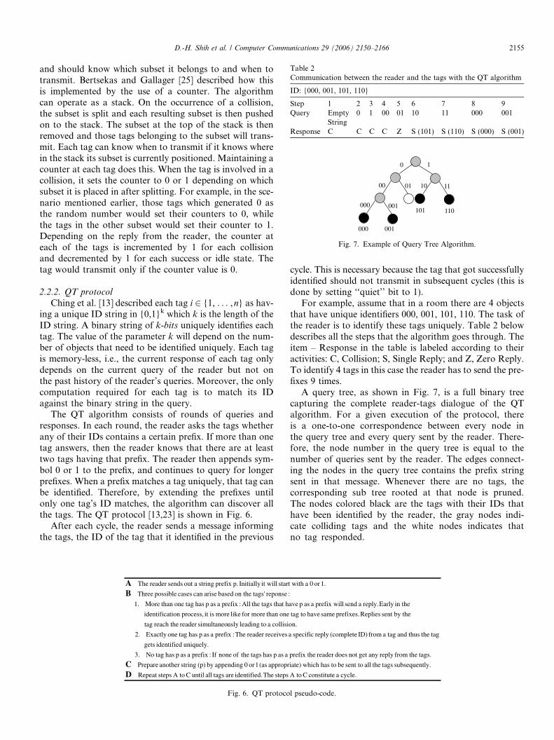
For example, assume that in a room there are 4 objectsthat have unique identifiers 000, 001, 101, 110. The task ofthe reader is to identify these tags uniquely. Table 2 belowdescribes all the steps that the algorithm goes through. Theitem – Response in the table is labeled according to theiractivities: C, Collision; S, Single Reply; and Z, Zero Reply.To identify 4 tags in this case the reader has to send the pre-fixes 9 times.
A query tree, as shown in Fig. 7, is a full binary treecapturing the complete reader-tags dialogue of the QTalgorithm. For a given execution of the protocol, thereis a one-to-one correspondence between every node inthe query tree and every query sent by the reader. There-fore, the node number in the query tree is equal to thenumber of queries sent by the reader. The edges connect-ing the nodes in the query tree contains the prefix stringsent in that message. Whenever there are no tags, thecorresponding sub tree rooted at that node is pruned.The nodes colored black are the tags with their IDs thathave been identified by the reader, the gray nodes indi-cate colliding tags and the white nodes indicates thatno tag responded.
cycle.aconstituteCA tostepsThe.identifiedare tagsalluntilCA tostepsRepeatDly.subsequent tags theallsent tobe tohas which e)appropriat(as1or0appendingby(p)stringanotherPrepareC
tags. thefromreplyanygetnotdoesreaderprefix theaasphas tags theofnoneIf:prefixaasphas tagNo3.
uniquely.identifiedgets
tag the thusand tagafromID)(completereplyspecificareceivesreaderThe:prefixaasphas tagoneExactly2.
collision.a toleadinguslysimultaneoreaderreach thetag
by thesentRepliesprefixes.samehave to tagone than moreforlikemoreisitprocess,tionidentifica
in theEarlyreply.asendlprefix wilaasphave that tags theAll:prefixaasphas tagone than More1.
:reponse tags'on thebasedarisecancasespossibleThreeB1.or0astart withit willInitiallyp.prefixstringaoutsendsreaderTheA
Fig. 6. QT protocol pseudo-code.
Table 2Communication between the reader and the tags with the QT algorithm
ID: {000, 001, 101, 110}
Step 1 2 3 4 5 6 7 8 9Query Empty
String0 1 00 01 10 11 000 001
Response C C C C Z S (101) S (110) S (000) S (001)
000 001
101 110
1 0
111000 01
000 001
Fig. 7. Example of Query Tree Algorithm.
D.-H. Shih et al. / Computer Communications 29 (2006) 2150–2166 2155

2.2.3. Variations of QT protocol
Ching et al. [13] also discussed and suggested some vari-ations of QT protocol in reducing the running time or thenumber of bits transmitted of the QT algorithm.
In reducing the running time, Ching et al. [13] suggestedshortcutting, aggressive advancement, and categorizationtechniques.
Shortcutting. It is a smart manifestation of skippinginternal nodes where collision is bound to happen. Consid-er any internal node of the query tree. This corresponds toa collision for certain prefix q during an execution of theQT algorithm. The algorithm will continue to search forthe tags by appending 1 and 0 to the prefix q. Without lossof generality, assume that the algorithm chooses to searchfor 0 first. If it turns out that there are no tags with prefixq0, and then we know that there are at least two tags withprefix q1. Therefore, the reader should skip the prefix q1 aswell. It has been shown to give an improved expected run-ning time bound of 2.665n � 1.
Aggressive advancement. Assume the reader knows thatthere are at least n unrecognized tags with prefix q. Forexample, this could be a prior knowledge: maximum num-ber of items in a checkout counters or the reader can detectthe strength of the response from the tags to estimate thenumber of tags. When n is large, it is very likely that theresponses for q1 and q0 will collide. The probability thateither one of the queries does not result in a collision is2� ð 1
2nþ n� 1
2nÞ ¼ nþ1
2n�1. Suppose we extend the prefix string
by two bits. That is, the reader will query q00, q01, q10, andq11. Two queries q1 and q0 with probability 1� nþ1
2n�1is
saved in this case. Note that we send more queries (com-pared with the original QT algorithm) only in the casewhere both q0 and q1 have exactly one tag with a matchingprefix. This cannot happen when n P 3.
Categorization. If the reader has some information aboutthe types of the tags, then it is possible to speed up the proto-col. For example, suppose a set S of IDs is given. Assume thereader knows that set S can be partitioned into S1, . . . ,Sm
such that all IDs in Si have prefix qi. Now the reader can justidentify each set Si independently. In particular, if we canpartition the tags into m groups, then the upper bound onthe expected running time is improved to 2.887n � m.
In reducing the number of bits transmitted, Ching et al.[13] also suggested Query-Tree short-long protocol andQuery-Tree incremental-matching protocol.
QT-sl (Query-Tree short-long) protocol.Note that in QTalgorithm; a lot of the k-bits responses from the tags wouldend up in collisions. To minimize these wastes, we can havetwo types of queries from the reader. The short queries willonly induce 1-bit responses from the tags, while the longqueries will induce the full tag IDs. The reader will senda long query only when it knows that only one tag matchesthe prefix. The QT-sl protocol [23] is shown in Fig. 8. Letthere be n tags to be identified. The expected reader com-munication complexity of QT-sl protocol is at most3.89kn + 3.89n. The expected tag communication complex-ity of QT-sl protocol is at most 2:21logn2 þ k þ 4:19.
QT-im (Query-Tree incremental-matching) protocol. It isvery similar to QT-sl protocol and it can reduce the expect-ed reader communication’s complexity. However, this opti-mization requires a tag to remember the bit position of theprefix it has matched so far. Therefore, the modified proto-col is no longer to be memory-less. Each tag has a bitmarker b 2 {1, . . . ,k}. When the tag is active, upon receiv-ing the query, the tag matches the query string startingfrom bit b. If the matching is successful, then bit markerb is incremented by 1. Any active tag that mismatcheswould go into the transient state, which is equivalent tobecome inactive in the next query unless that query con-tains the reactivate command. Moreover, it is no longernecessary to supply a prefix with the long query. The tagcommunication complexity of QT-im protocol is the sameas that of QT-sl protocol. However, the number of bits sentby the reader is reduced. The expected reader communica-tion complexity of QT-im protocol is at most4:42nlongn2 þ 12:18n.
2.3. I-code protocol
I-Code protocol is a stochastic passive tag identifica-tion protocol based on the framed-slotted Aloha concept.Each tag transmits its information in a slot that itchooses randomly based on the seed sent by the reader.In each slot, as shown in Fig. 9, can happen: empty slots(no tag), filled slots (a single tag), or garbled slots (multi-ple tags transmit). The reader can detect the identity ofthe tag when a single tag transmits in a time slot. Whenmultiple tags use the same slot a collision occurs anddata gets lost. The reader can vary the frame size, theactual size of a slot is chosen according to the amountof data requested [15,17].
Harald [17] shows a tag reading cycle consists of twosteps:
1. Reader fiI, rnd, N2. T!ST ðN ;rndÞ Reader: dataT,I for all tags T
In the first step, the reader device broadcasts a requestfor data. I denotes what data are requested by specifyingan interval of the available 64 bytes of tag memory;rnd 2 [0,31] is a random value whose use is explainedbelow; N 2 {1,4,8,16,32,64,128,256} is the frame size anddenotes the number of available slots for responses. In sec-ond step, tags that are in the proximity of the antennaresponse, where fis denotes a tag sending in slot s and0 6 s < N. A tag T uses a tag-specific function ST to com-pute its response slot number by using the frame size andthe random value as parameters and the random valueare supposed to avoid the same collisions occurringrepeatedly.
The reader starts with an estimate of the number ofslots required to identify all the tags within its detectionrange. The tags select a slot at random from thoseavailable in a read cycle and transmit the information
2156 D.-H. Shih et al. / Computer Communications 29 (2006) 2150–2166

requested by the reader. The reader detects the numberof slots by a triple of numbers c = Æc0,c1,ckæ, where c0stands for the number of slots in the read cycle inwhich 0 tags have transmitted, c1 denotes the numberof slots in which a single tag transmitted and ck standsfor the number of slots in which multiple tags aretransmitted.
There are two estimation functions that yield approxi-mations for n. The first estimation function is obtainedthrough the observation that a collision involves at leasttwo different tags. Therefore a lower bound on the valueof can be obtained by the simple estimation function elb,which is defined as [17]:
elbðN ; c0; c1; ckÞ ¼ c1 þ 2ck.
Alternative estimation function uses the distancebetween the read result and the expected value vector todetermine the value of n for which the distance becomesminimal. This estimation function evd is defined as
evdðN ; c0; c1; ckÞ ¼ minn
aN ;n0
aN ;n1
aN ;nP2
0B@
1CA�
c0c1ck
0B@
1CA
�������
�������.
The reader re-estimates the number of slots for the nextcycle based on its estimate of the number of tags computedin the current cycle. Let n_new be the new estimated valueof the number of tags as computed from Æc0,c1,ckæ of thecurrent read cycle. A range for the estimated number oftags is defined as (n_low,n_high) {n_low corresponds tothe lower limit of the range and n_high the upper limit}.Various N values corresponding to specific ranges havebeen found from experiments and tabulated in Table 3[7]. If n_new falls in the range (n_low,n_high) {i.e., n_low -n_new 6 n_high} then based on Table 3 the number ofslots N (for the next cycle) is chosen corresponding to thisparticular range of (n_low,n_high). For example, ifn 2 [17,27], both 32 and 64 are appropriate choices for Nsince both settings yield similar times. The Table 3 lookupcan be implemented in a way that is shown in Fig. 10 [17].
Once the reader fixes the number of slots for detectingthe tags, it uses a stochastic function to calculate the totalnumber of read cycle(s) that are necessary to detect all the
Fig. 8. QT-sl protocol pseudo-code.
F G E E F G F E GG EF E E EG FF
E: empty
F: filled
G: garbled
Fig. 9. Tags are randomly allocated to slots within a frame (above). Thisresult in some slots remaining empty and others contain one or more tags(below).
D.-H. Shih et al. / Computer Communications 29 (2006) 2150–2166 2157

tags with a certain level of accuracy. For a fixed frame sizeN, the time Ta required to achieve an assurance level a isgiven by [17]
T a ¼ s0 � tN ;where s0 is the minimum number of read cycles required toidentify all n tags in the field with probability a. s0 is there-fore the minimum value of s for which the following condi-tion holds:
Qsqð0Þ½n� P a;
where Q refers to the transitional probability matrix of thenumber of tags detected in successive read cycle, s standsfor the number of read cycles, q (0) refers to the vector ofrandom variables and a refers to the level of accuracy re-quired for detecting the tags from the available set. Theresulting vector of the product Qsq (0) contains the proba-bilities of identifying k tags after s read cycles,k = 0,1, . . . ,n. The above process of tag detection is thusan adaptive one achieved by iterating through the same se-quence of steps to get an estimate of the number of tags in
the environment which is reasonably close to the actualone. The algorithm is shown in Fig. 11 [15,17].
2.4. Contact-less protocol
The contact-less protocol [18] is based on the tree split-ting methodology described earlier. The terminologies thatthe authors use for the reader and tag are transceiver andtransponder, respectively. The basic idea is to identifyone bit of the identification code in every arbitration step.One instance of an arbitration process will identify a taguniquely. Each arbitration process will have N arbitrationsteps, where N is the number of bits in the identificationcode.
Initially, all the tags are in wait state and listen activelyto the reader commands as shown in Fig. 12. Thus, all thetags are active in the beginning. The reader requests theactive tags for a given bit position of their identificationcode during a particular slot in the arbitration step. Thetags use a modulation scheme [22], which identifies a logi-cal ‘‘0’’ in the specified bit position with ‘‘00ZZ’’ in a slot(where Z can be thought of as a tag transmission with nomodulation). Logical ‘‘1’’ is identified with the sequence‘‘ZZ00’’. In this way, the reader can recognize the respons-es from all the tags even though they have different bits intheir identification sequence. This step divides the uniden-
Fig. 10. Choosing a frame size.
Fig. 11. Procedure to adaptively read a static set of tags.
Table 3Optimality intervals for frame sizes
N slots 1 4 8 16 32 64 128 256
n_low – – – 1 10 17 51 112n_high – – – 9 27 56 129 1
other
commands
Tag active
BitVal=ContBit
Bit arbitration step
Arbitration
finished
BitVal ContBit
arbitration
aborted
WAIT
for new
command
START
arbitration
process
SEND
nth identification
bit (BitVal)
CONTINUE
get nth identification
bit (ContBit) from reader
FINISH
arbitration
set tag inactive
Fig. 12. A full arbitration process.
2158 D.-H. Shih et al. / Computer Communications 29 (2006) 2150–2166
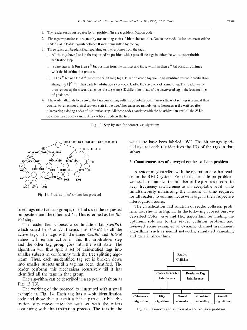
tified tags into two sub groups, one had 0’s in the requestedbit position and the other had 1’s. This is termed as the Bit-Val step.
The reader then chooses a continuation bit (ConBit),which could be 0 or 1. It sends this ConBit to all theactive tags. The tags with the same ConBit and BitVal
values will remain active in this Bit arbitration stepand the other tag group goes into the wait state. Thealgorithm will thus split a set of unidentified tags intosmaller subsets in conformity with the tree splitting algo-rithm. Thus, each unidentified tag set is broken downinto smaller subsets until a tag has been identified. Thereader performs this mechanism recursively till it hasidentified all the tags in that group.
The algorithm can be described in a step-wise fashion asFig. 13 [13].
The working of the protocol is illustrated with a smallexample in Fig. 14. Each tag has a 4 bit identificationcode and those that transmit a 0 in a particular bit arbi-tration step moves into the wait set with the otherscontinuing with the arbitration process. The tags in the
wait state have been labeled ‘‘W’’. The bit strings speci-fied against each tag identifies the IDs of the tags in thatsubset.
3. Countermeasures of surveyed reader collision problem
A reader may interfere with the operation of other read-ers in the RFID system. For the reader collision problem,we need to minimize the number of frequencies needed tokeep frequency interference at an acceptable level whilesimultaneously minimizing the amount of time requiredfor all readers to communicate with tags in their respectiveinterrogation zones.
The classification and solution of reader collision prob-lems was shown in Fig. 15. In the following subsections, wedescribed Color-wave and HiQ algorithms for finding theoptimum solution to the reader collision problem andreviewed some examples of dynamic channel assignmentalgorithms, such as neural networks, simulated annealingand genetic algorithms.
Fig. 13. Step by step for contact-less algorithm.
W
W
W
W
0010, 1011, 1001, 0001, 0011, 0101, 1101, 0110
1011, 1001, 1101
1101
1101
1011, 1001
1011
1011
1001
1001
0010, 0001, 0011, 0101, 0110
0010, 0001, 0011
0001
0001
0001
0010, 0011
0010
0010
0011
0011
0101, 0110
0101
0101
0110
0110
Fig. 14. Illustration of contact-less protocol.
Reader
Collision
Reader to Reader
Interference
Color-ware
Algorithm
HiQ
Algorithm
Neural
networks
Simulated
annealing
Genetic
algorithms
Reader to Tag
Interference
Fig. 15. Taxonomy and solution of reader collision problems.
D.-H. Shih et al. / Computer Communications 29 (2006) 2150–2166 2159

3.1. Color-wave
To achieve optimal frequency channel assignment, apair of distributed algorithms called Distributed ColorSelection (DCS) and Variable-Maximum Distributed Col-or Selection (VDCS or Color-wave) are introduced[20,21]. The goal of both algorithms is to color a readernetwork such that each reader node has the smallestpossible number of adjacent nodes with the same color.This approach allows easy reservation of time slots; acolor is a periodic reservation for collision-free transmis-sion of data. Color-wave additionally attempts tooptimize the graph to the smallest number of total colorsrequired to achieve a particular percentage of successfultransmissions.
3.1.1. Distributed color selection
This approach allows easy reservation of time slots;a color is a periodic reservation for collision-free trans-mission of data. A reader with a queued request fortransmission transmits only in its color (time slot). Ifthe transmission collides with another reader, the trans-mission request is discarded. Furthermore, the readerrandomly chooses a new color and reserves this color,causing all of its neighbors to select a new color. Thisswitch and reservation action is referred to as a‘‘kick’’.
The maximum colors variable (max_colors) is an inputto the algorithm, and does not change throughout thefunctioning of the algorithm. Each reader keeps trackof what color it believes the current time slot to be (time-slot_ID). The distributed nature of the algorithm doesnot require synchronization between timeslot_ID. DCSis implemented with three separate subroutines detailedin Fig. 16 [20]. The first subroutine manages transmis-sions. The second subroutine manages collisions andthe reservation of a new ‘‘color’’ or time slot. The thirdsubroutine manages kick resolution, or communicationwith other readers. Each reader must calculate for each
kick received whether its current color is the color refer-enced by the kick.
DCS is a greedy algorithm; a node’s chances of collid-ing immediately after experiencing a collision are mini-mized at the expense of its neighbors. However, agreedy algorithm caters more to our needs than an altru-istic algorithm, as we wish a communicating reader tocommunicate with its tags as soon as possible after queu-ing the request.
3.1.2. Variable-maximum distributed color selection
In DCS, the maximum colors variable (max_colors) isfixed. In a reader network with a variable probability oftransmission between nodes and times of day, a single inputfor colors in the algorithm does not provide for flexibility.Thus, a mechanism for dynamically changing the maximumnumber of colors available at a reader is needed. Color-wave[20,21] is a simple, distributed, on-line algorithm that finds afeasible solution to the reader collision problem. The distrib-uted nature of the algorithm allows each reader to minimizecollisions based upon local information. Global communi-cation and information sharing are not required. The Col-or-wave algorithm is representative of algorithms that usea distributed system with no guaranteed method of commu-nicating between neighboring nodes to manage a TDMAreservation anti-collision system among a network ofreaders.
In Color-wave, each reader monitors the percentage ofsuccessful transmissions. Five inputs to the algorithmdetermine when a reader changes its local value ofmax_colors:
1. UpSafe: the safe percentage at which to increasemax_colors.
2. UpTrigs: the trigger percentage at which to increasemax_colors if a neighboring reader is also switching toa max_colors higher than that of this reader.
3. DnSafe, DnTrig: analogues of UpSafe, UpTrig, exceptdecreasing max_colors.
Fig. 16. DCS pseudo-code.
2160 D.-H. Shih et al. / Computer Communications 29 (2006) 2150–2166

4. MinTimeInColor: the minimum number of time slotsbefore the Color-wave algorithm will change max_colorsagain after initialization or changing max_colors.
Color-wave builds upon the DCS algorithm; the addi-tional subroutines for Color-wave are detailed in Fig. 17[20]. When a reader executing Color-wave reaches a Safepercentage to change its own value for max_colors, it willsend out a kick to all neighboring readers. If the phenom-enon that is causing it to exceed a Safe percentage is localto that reader, the other readers will not have passed theirown Trig percentages and will not respond. However, if thephenomenon causing the collision value to exceed a Safethreshold is widespread, neighboring readers will mostlikely have exceeded their own Trig thresholds, and a ‘‘kickwave1’’ will ensue. As kicks spread from the initiating read-er throughout the entire system, a large portion (or all) ofthe readers in a reader system may change their value ofmax_colors.
3.2. HiQ algorithm
Another anti-collision protocol for optimal frequencychannel assignment is the HiQ algorithm [22]. The HiQ isan online algorithm based on Q-learning to solve the readercollision problem. Q-learning is a form of reinforcementlearning [26,27]. Fig. 18 diagrams the agent-environmentinteraction. The environment is modeled as finite-state dis-crete-time stochastic dynamical system. The agent andenvironment interact at each of a sequence of discrete timesteps, t = 0,1,2, . . . At each time step t, the agent receivessome representation of the environment’s state, st 2 S,where S is the set of possible states, and on that basisselects an action, at 2 A (st), where A (st) is the set of actionsavailable in state st. One time step later, in part as a conse-quence of its action, the agent receives a numerical reward,rt+1 2 R, and finds itself in a new state, st+1. The goal of theQ-learning agent is to find an optimum policy p*(s,a),which maximizes/minimizes the cumulative measure ofthe return (reward/cost) rt = r (s,a) received over time.
The HiQ algorithm utilizes a hierarchical control struc-ture with three basic tiers. At the lowest tier are readers.The readers communicate when they have been granted afrequency and a time slot to do so. Readers only haveknowledge of the frequency and time slot they have beenallocated. They are capable of detecting collisions withother readers by communicating with other readers withinits interrogation zone, those with overlapping interrogationzones. For example, in Fig. 19, Readers B and C are withinthe interrogation zone of Reader A. When A is granted afrequency and a time slot, it begins reading. During thistime, it also pings its neighbors (B and C) to see if theyare reading. Once Readers B and C receive the ping, theyrespond with whether or not they are reading at the time,and if they are, what frequency they are using. Reader Ais responsible for the collisions detection processing. WhenReader A receives the ping responses from Readers B andC, it checks to see if there are collisions, and if so, whattype of collisions. If two readers are communicating usingthe same time slot, there will be tag interference. If thesereaders are also using the same frequency, the reader will
Fig. 17. Color-wave pseudo-code.
Agent
Environment
ta
action
1+tr
1+ts
tr
reward
ts
state
Fig. 18. The agent-environment interaction in reinforcement learning.
A
B
C
Fig. 19. Three readers configuration.
D.-H. Shih et al. / Computer Communications 29 (2006) 2150–2166 2161
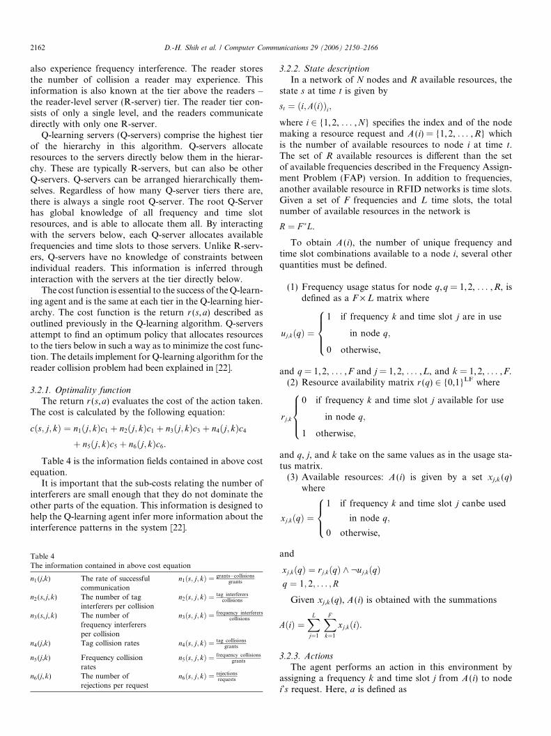
also experience frequency interference. The reader storesthe number of collision a reader may experience. Thisinformation is also known at the tier above the readers –the reader-level server (R-server) tier. The reader tier con-sists of only a single level, and the readers communicatedirectly with only one R-server.
Q-learning servers (Q-servers) comprise the highest tierof the hierarchy in this algorithm. Q-servers allocateresources to the servers directly below them in the hierar-chy. These are typically R-servers, but can also be otherQ-servers. Q-servers can be arranged hierarchically them-selves. Regardless of how many Q-server tiers there are,there is always a single root Q-server. The root Q-Serverhas global knowledge of all frequency and time slotresources, and is able to allocate them all. By interactingwith the servers below, each Q-server allocates availablefrequencies and time slots to those servers. Unlike R-serv-ers, Q-servers have no knowledge of constraints betweenindividual readers. This information is inferred throughinteraction with the servers at the tier directly below.
The cost function is essential to the success of theQ-learn-ing agent and is the same at each tier in the Q-learning hier-archy. The cost function is the return r (s,a) described asoutlined previously in the Q-learning algorithm. Q-serversattempt to find an optimum policy that allocates resourcesto the tiers below in such a way as to minimize the cost func-tion. The details implement for Q-learning algorithm for thereader collision problem had been explained in [22].
3.2.1. Optimality functionThe return r (s,a) evaluates the cost of the action taken.
The cost is calculated by the following equation:
cðs; j; kÞ ¼ n1ðj; kÞc1 þ n2ðj; kÞc1 þ n3ðj; kÞc3 þ n4ðj; kÞc4þ n5ðj; kÞc5 þ n6ðj; kÞc6.
Table 4 is the information fields contained in above costequation.
It is important that the sub-costs relating the number ofinterferers are small enough that they do not dominate theother parts of the equation. This information is designed tohelp the Q-learning agent infer more information about theinterference patterns in the system [22].
3.2.2. State description
In a network of N nodes and R available resources, thestate s at time t is given by
st ¼ ði;AðiÞÞi;where i 2 {1,2, . . . ,N} specifies the index and of the nodemaking a resource request and A (i) = {1,2, . . . ,R} whichis the number of available resources to node i at time t.The set of R available resources is different than the setof available frequencies described in the Frequency Assign-ment Problem (FAP) version. In addition to frequencies,another available resource in RFID networks is time slots.Given a set of F frequencies and L time slots, the totalnumber of available resources in the network is
R ¼ F �L.
To obtain A (i), the number of unique frequency andtime slot combinations available to a node i, several otherquantities must be defined.
(1) Frequency usage status for node q,q = 1,2, . . . ,R, isdefined as a F · L matrix where
uj;kðqÞ ¼
1 if frequency k and time slot j are in use
in node q;
0 otherwise,
8>><>>:
and q = 1,2, . . . ,F and j = 1,2, . . . ,L, and k = 1,2, . . . ,F.(2) Resource availability matrix r (q) 2 {0,1}LF where
rj;k
0 if frequency k and time slot j available for use
in node q;
1 otherwise;
8>><>>:
and q, j, and k take on the same values as in the usage sta-tus matrix.(3) Available resources: A (i) is given by a set xj,k (q)
where
xj;kðqÞ ¼1 if frequency k and time slot j canbe used
in node q;
0 otherwise,
8><>:
and
xj;kðqÞ ¼ rj;kðqÞ ^ :uj;kðqÞq ¼ 1; 2; . . . ;R
Given xj,k (q), A (i) is obtained with the summations
AðiÞ ¼XL
j¼1
XFk¼1
xj;kðiÞ.
3.2.3. Actions
The agent performs an action in this environment byassigning a frequency k and time slot j from A (i) to nodei’s request. Here, a is defined as
Table 4The information contained in above cost equation
n1 (j,k) The rate of successfulcommunication
n1ðs; j; kÞ ¼ grants�collisionsgrants
n2 (s, j,k) The number of taginterferers per collision
n2ðs; j; kÞ ¼ tag interfererscollisions
n3 (s, j,k) The number offrequency interferersper collision
n3ðs; j; kÞ ¼ frequency interfererscollisions
n4 (j,k) Tag collision rates n4ðs; j; kÞ ¼ tag collisionsgrants
n5 (j,k) Frequency collisionrates
n5ðs; j; kÞ ¼ frequency collisionsgrants
n6 (j,k) The number ofrejections per request
n6ðs; j; kÞ ¼ rejectionsrequests
2162 D.-H. Shih et al. / Computer Communications 29 (2006) 2150–2166

a ¼ j; k 2 f1; 2; . . . ;Rg and xj;kðiÞ ¼ 1.
3.3. Other algorithms
There have been a great number of algorithms devel-oped for solving the frequency assignment problem. Thealgorithms vary greatly and have many fundamental differ-ences, depending on the type of frequency assignmentproblem they are trying to solve. Many rely on centralizedcontrol for channel assignment, while others boast distrib-uted control where individual transmitters are responsiblefor communication. Some examples of dynamic channelassignment algorithms are neural networks, simulatedannealing and genetic algorithms [28–30].
In a neural network, a system of artificial neurons ismathematically created. In this system, the neurons repre-sent a single cellular base station and a single channel thatbase station can use. The constraints and optimization cri-teria of the system are translated into an energy function,which the neural network tries to minimize. Calculatingthis energy function and combining it with weighted inputparameters results in a state for each neuron. The output ofthese neurons is based on the internal state of each neuronand determines whether or not a channel can be used in abase station. With this algorithm, a network of 25 base sta-tions with 73 channels each was able to converge to anoptimum assignment [28].
Simulated annealing is a generalization of local search.The algorithm starts with an initial solution and beginsmaking random changes to channel assignments in a radionetwork. The algorithm always accepts assignmentchanges that improve the overall reward, and acceptschanges that do not improve the reward (deteriorations)with some probability. The algorithm uses a control vari-able T to restrict the number of deteriorations and stopswhen T reaches its terminal value. Simulated annealingalgorithms have been shown to be capable of convergingto assignment that did not violate frequency constraints32–52% of the time, depending on the complexity of thenetwork [29].
Genetic algorithms are a form of blind local search. In agenetic algorithm approach to channel assignment, a singlesolution is an assignment scheme for all the base stations.The genetic algorithm takes a set of solutions as the popu-
lation, and begins the evolutionary process. First, membersof the population are selected based on their fitness (perfor-mance measure). To avoid converging at local minima(when only the fittest are selected) the selection is done ina biased random manner: fitter members are more likelyto be chosen than the weaker members. Through crossover,information is exchanged between members of the selectedpopulation, resulting in reproduction that creates new solu-tions. During reproduction, genes (base stations) mayundergo additional random changes at a mutation rate.The process is repeated until a solution is found whereno interference constraints are violated [30].
4. Comparative view of surveyed protocol
The problems that occur in data transferring betweenreaders and tags in an RFID system are shown inFig. 20. In Fig. 20(a), it explains the problem in transmis-sion of data from many individual tags to the reader. Whena reader attempts to obtain the unique ID number of eachtag, messages from the tags can collision and cancel eachother out. Fig. 20(b) explains the problem when two read-ers with overlapping interrogation zones communicateusing the same frequency at the same time, each mayencounter difficulty in communication with tags due tointerfering signals transmitted by the other reader.Fig. 20(c) explains the problem when one tag is simulta-neously located in the interrogation zones of two or morereaders and more than one reader attempts to communi-cate with that tag at the same time. Regardless of Figs.20(b) or (c), interference detected by one reader or causedby another reader is referred to as a reader collision andtag interference can occur without reader interference whilereader interference always has tag interferences as well. Wehave surveyed all possible protocols, classified these prob-lems and shown them in Fig. 21.
4.1. Tag collision
Anti-collision methods in tags have similarities to anti-collision algorithms in networking. However, RFID tagspose a number of problems that arise from the very limitedresources. A common classification of anti-collision algo-rithms is based upon how the tags respond. In probabilistic
R1 R2
R3
Tag
Tag
Tag
Tag
Tag Interference
R1 R2
R3
Tag
Tag
Tag
Tag
Reader Interference
Tag
Tag Tag
Tag
Tag
Tag
R1
Tag Collision
a b c
Fig. 20. Data transferring between readers and tags in an RFID system.
D.-H. Shih et al. / Computer Communications 29 (2006) 2150–2166 2163

algorithms, the tags respond at randomly generated times.Many probabilistic algorithms are based on the Alohascheme in networking [31]. The times at which readerscan respond can be slotted or continuous. Deterministicschemes are those in which the reader sorts through tagsbased on their unique identification number. The simplestdeterministic scheme is the splitting method (binary tree-walking scheme), in which the reader traverses the tree ofall possible identification numbers.
Sarma et al. [32] described the performance metrics thatare traded-off by these algorithms and their variantsinclude: (1) the speed at which tags can be read, (2) the out-going bandwidth of the reader signal, (3) the bandwidth ofthe return signal, (4) the amount of state that can be reli-ably stored on the tag, (5) the tolerance of the algorithmto different types of noise in the field, (6) the cost of thetag, (7) the cost of the reader, (8) the ability to tolerate tagswhich enter and leave the field during the inventory-takingprocess, (9) the desire to count tags exactly as opposed to
sampling them, and finally, and (10) the range at whichtags can be read.
Table 5 shows a contrast with most multiple accesscollision-resolution methods surveyed in this paper. Aninteresting conclusion to draw from Table 5 is that noparticular algorithm seems to emerge as the preferredmethod to resolve collision. The choice of algorithmfor implementation in systems aimed for the market isfairly well distributed between Aloha and its two deriva-tives, Slotted-Aloha and Framed-slotted Aloha. In deter-ministic anti-collision algorithms, polling, tree algorithm,and QT protocol have the same time complexity andread accuracy rate for n1 = n2. If there is a cost consid-eration, polling protocol is the choice. If we emphasizecost and time both, QT protocol will be better. In prob-abilistic anti-collision algorithms, tag-driven proceduresare slower and more inflexible than reader-driven proce-dures. Therefore, if there is time concern, I-Code proto-col is a better choice. Table 5 also shows that most
RFID Collision Problem
Color-wave
Algorithm
HiQ
Algorithm
Neural
network
Simulated
annealing
Genetic
algorithms
Tag
Interference
Reader
Interference
Reader
Collision
Tag
Collision
Splitting
Methods
I-Code
Protocol
Contact-less
Protocol
PollingSuperTag
Fig. 21. Taxonomy of anti-collision resolution for RFID collision problem.
Table 5Comparison of tag collision-resolution
Criteria Protocols
Tag-driven Reader-driven
SuperTag Polling Splitting methods I-Code Contact-less
Tree algorithm QT protocol
Deterministic � � � �Probabilistic � �TTF/RTF TTF RTF RTF RTF RTF RTFAloha �Slotted-Aloha � �Framed-slotted Aloha �Switch-off � � � � �Slow-down � �Terminating/Muting �Reader ‘‘Carrier Sense’’ � �Accuracy level Close to 100% 100% 100% 100% Close to 100% 100%Time complexity – O (n1) O (n2) O (n1) t0* s + TN O (2N)Message complexity – O (m (N + 1)) mlongm2 2:21klongn2 þ 4:19k N (m*p) + N (m* s) O (m(N + 1))
Where n1, total number of unique tags possible with a possible with a tag id of length k; n2, the number of tags that need to be identified; TN, time requiredto estimate N; N, length of the tag identification number; m, the number of tags that needs to be identified; (m*p), number of read cycles required toestimate N; (m* s), number of read cycle performed with fixed N.
2164 D.-H. Shih et al. / Computer Communications 29 (2006) 2150–2166

systems encountered implement at least one of the exten-sions mentioned.
4.2. Reader collision
The solution of a reader collision problem is to allocatefrequencies over time to a set of readers without collision.Table 6 shows a contrast with five algorithms for resolvingthe reader collision problem. The algorithms vary greatlyand have many fundamental differences. Many rely on cen-tralized control for channel assignment, while others boastdistributed control where individual transmitters areresponsible for communication. Reader collision problemshave some similarities to frequency assignment problems inmobile telephone systems. However, RFID systems areunable to discriminate between two readers communicatingwith them simultaneously. Therefore, two readers thatcommunicate with the same tag must communicate at dif-ferent times. In a cooperative, trusted environment, readercollisions can be handled in a fairly seamless way. Never-theless, complications may arise in the execution of com-mands that change the state of the tag. If another readerinterrupts the reader executing a series of state changingactions, it may be forced to relinquish control over thetag. The new reader that acquires the tag may furtherchange the state of the tag without the cooperation of thefirst reader. Transactions between readers and tags musttherefore be brief and atomic.
5. Conclusion
We have surveyed and classified a series of anti-collisionprotocols for RFID arbitration in this paper. In tag identi-fication problem, the challenge that emerges for RFID sys-tems where multiple tags are present in the reader’s field ismaximizing the number of tags accessed for information,while simultaneously minimizing the number within thetime needed to do so. In many ways, the reader collisionproblem is simpler than the frequency assignment problem.However, the time and frequency usage constraints on thereaders and the RFID system have a more significantimpact on the performance of the RFID system. The phe-nomenon of tag interference is specific to the reader colli-sion problem and is not found in the previously studiedfrequency assignment problem.
A comparative view of surveyed protocol was con-cluded in Section 5 which are provided for otherresearchers to improve. In further research, it remainschallenging to find a procedure that would take environ-mental effects into account. We hope this paper will helpimplement pervasive computing environments thatemploy RFID systems.
Acknowledgments
The author thanks to the National Science Council ofTaiwan for Grants NSC 94-2218-E-194-005 and NSC 94-2213-E-224-036 to part of this research.
References
[1] B. Johansson, An Introduction to RFID – Information Security andPrivacy Concerns, TDDC03 Projects, Spring, 2004.
[2] S.A. Weis, S. Sarma, E.R.L. Riovest, D.W. Engels, Security andprivacy aspects of low-cost radio frequency identification systems,in: Lecture Notes in Computer Science, vol. 2802, 2004, pp. 201–212.
[3] A. Juels, R. Pappu, Squealing euros: privacy protection in RFID-enabled banknotes, in: Lecture Notes in Computer Science, vol. 2742,2003, pp. 103–121.
[4] S.H. Weigart, Physical security devices for computer subsystems: asurvey of attacks and defenses, in: Lecture Notes in ComputerScience, vol. 1965, 2000, pp. 302–317.
[5] Royal Air Force, History, 1940. <http://www.raf.mod.uk/history/line1940.html/>.
[6] R. Anderson, M. Kuhn, Low cost attacks on tamper resistantdevices, in: Lecture Notes in Computer Science, vol. 1361, 1997,pp. 125–136.
[7] A. Juels, Minimalist cryptography for low-cost RFID tags, in:Lecture Notes in Computer Science, vol. 3352, 2004, pp. 149–164.
[8] A. Juels, R.L. Rivest, M. Szydlo, The blocker tag: selective blockingof RFID tags for consumer privacy, in: ACM Conference onComputer and Communications Security 103–111, Washington,DC, USA, October, 2003.
[9] A.R. Koelle, S.W. Depp, J.A. Landt, R.E. Bobbett, Short-rangePassive Telemetry by Modulated Backscatter of Incident CW RFCarrier Beams, Biotelemetry, vol. 3, 1976, pp. 337–340.
[10] K. Finkenzeller, RFID Handbook: Radio-Frequency IdentificationFundamentals and Applications, John Wiley, New York, 2000, pp.200–219.
[11] D. Krebs, M.J. Liard, White Paper: Global Markets and Applicationsfor Radio Frequency Identification, Venture Development Corpora-tion (2001).
[12] T.S. Flor, W. Niess, G. Vogler, RFID: the integration of contact-lessidentification technology and mobile computing, in: Seventh Inter-
Table 6Comparison of reader collision-resolution
Method Criteria
Optimize function Centralizedcontrol
Distributedcontrol
Fixed ChannelAssignment (FCA)
Dynamic Channel Assignment(DCA)
Colorwave algorithm Smallest possiblecolor number
� � �
HiQ algorithm Cost function � � �Neural network Energy function � �Simulated annealing Reward value � �Genetic algorithm Performance value � �
D.-H. Shih et al. / Computer Communications 29 (2006) 2150–2166 2165

national Conference on Telecommunications, vol. 2, Zagreb, Croatia,June 11–13, 2003, pp. 619–623.
[13] C. Law, K. Lee, K.Y. Siu, Efficient memory-less protocol for tagidentification, in: Proceedings of the 4th International Workshop onDiscrete Algorithms and Methods for Mobile Computing andCommunications, Boston, Massachusetts, USA, August 11, 2000,pp. 75–84.
[14] D.R. Hush, C. Wood, Analysis of tree algorithms for RFIDarbitration, in: IEEE International Symposium on InformationTheory, 16–21 August, 1998, p. 107.
[15] Harald Vogt, Multiple object identification with passive RFID tags,in: Proceedings of IEEE International Conference on Systems, Manand Cybernetics, vol. 3, Hammamet, Tunisia, 6–9 October, 2002, 6pp.
[16] F. Zhou, D. Jin, C.L. Huang, M. Hao, Optimize the powerconsumption of passive electronic tag for anti-collision schemes, in:Proceedings of the Fifth International ASIC Conference, October,2003, pp. 1213–1217.
[17] Harald Vogt, Efficient object identification with passive RFID tags,in: Proceedings International Conference on Pervasive Computing,April, 2002, pp. 98–113.
[18] M. Jacomet, A. Ehrsam, U. Gehrig, Contact-less identification devicewith anti-collision algorithm, in: IEEE Computer Society, Conferenceon Circuits, Systems, Computers and Communications, Athens, 4–8July, 1999.
[19] D.W. Engels, S.E. Sarma, The reader collision problem, in: Proceed-ings of IEEE International Conference on Systems, Man andCybernetics, vol. 3, Hammamet, Tunisia, 6–9 October, 2002, 6 pp.
[20] J. Waldrop, D.W. Engels, S.E. Sarma, Colorwave: an anticollisionalgorithm for the reader collision problem, in: IEEE WirelessCommunications and Networking Conference, March, 2003, pp.1206–1210.
[21] J. Waldrop, D.W. Engels, S.E. Sarma, Colorwave: A MAC for RFIDreader networks, in: IEEEWireless Communications and NetworkingConference, 2003, pp. 1701–1704.
[22] J.K. Ho, Solving the Reader Collision Problem with a Hierarchical Q-learning Algorithm, S.B. Electrical Engineering and ComputerScience Massachusetts Institute of Technology, 2001.
[23] C. Abraham, V. Ahuja, A.K. Ghosh, P. Pakanati, InventoryManagement using Passive RFID Tags: A Survey, Department ofComputer Science, The University of Texas at Dallas, Richardson,Texas, pp. 1–16, October, 2002.
[24] J.I. Capetanakis, Tree algorithms for packet broadcast channels,IEEE Trans. Informat. Theory 25 (1979) 505–515.
[25] D. Bertsekas, R. Gallager, Data Networks, second ed., Prentice-Hall,Englewood-Cliffs, NJ, 1992.
[26] S. Haykin, J. Nie, A dynamic channel assignment policythrough Q-learning, IEEE Trans. Neural Networks 10 (1999)1443–1455.
[27] R.S. Sutton, A.G. Barto, Reinforcement Learning: An Introduction,A Bradford Book, 1998, pp. 51–52.
[28] D. Kunz, Channel assignment for cellular radio usingneural networks, IEEE Trans. Vehicular Technol. 40 (1991)188–193.
[29] M. Duque-Anton, D. Kunz, B. Ruber, Channel assignment forcellular radio using simulated annealing, IEEE Trans. VehicularTechnol. 42 (1993) 14–21.
[30] W.K. Lai, G.G. Coghill, Channel assignment for a homogenouscellular network with genetic algorithms, IEEE Trans. VehicularTechnol. 45 (1996) 91–96.
[31] B. Bing, Broadband Wireless Access, Kluwer Academic Publishers,Boston, 2000.
[32] S.E. Sarma, S.A. Weis, D.W. Engels, RFID Systems and security andprivacy implications, in: Lecture Notes in Computer Science, vol.2523, 2003, pp. 454–469.
Dong-Her Shih received his Ph.D. degree in Elec-trical Engineering from National Cheng KungUniversity, Taiwan, in 1986. He is a professor ofInformation Management Department, NationalYunlin University of Science and Technology,Douliu, Yunlin, Taiwan. He has published over 30articles in refereed information system journals.He also serves as an Asian Editor in InternationalJournal of Mobile Communications. His currentresearches include network security, intrusiondetection, wireless network, E-commerce security,RFID systems and peer-to-peer network.
Po-Ling Sun is a graduate student in InformationManagement, National Yunlin University ofScience and Technology, Douliu, Yunlin,Taiwan, from 2003. Her current interests includeE-commerce security and RFID systems.
David C. Yen is a professor of MIS and chair ofthe Department of Decision Sciences and Man-agement Information Systems at Miami Univer-sity. He received a Ph.D. in MIS and Master ofSciences in Computer Science from the Univer-sity of Nebraska. Professor Yen is active inresearch, he has published three books and manyarticles which have appeared in Communicationsof the ACM, Decision Support Systems, Infor-mation and Management, International Journalof Information Management, Information Sci-
ences, Journal of Computer Information Systems, Interfaces, Telematicsand Informatics, Computer Standards and Interfaces, Information Soci-ety, Omega, International Journal of Organizational Computing andElectronic Commerce, Communications of AIS, and Internet Researchamong others. He was also one of the co-recipients for a number of grantssuch as Cleveland Foundation (1987–1988), GE Foundation (1989), andMicrosoft Foundation (1996–1997).
Dr. Shi-Ming Huang received his Ph.D. degree atthe School of Computing and Information Sys-tems, University of Sunderland, U.K. He is cur-rently a Head of Accounting and InformationTechnology Department and a Director for theResearch Center of e-Manufacturing and e-Commerce at National Chung Cheng University,Taiwan. He is also a professor in the Departmentof Information Management. He is 2006 Presi-dent for International Chinese Information Sys-tems Association (ICISA). He has published five
books, three business software and over 40 articles in refereed informationsystem journals, such as Decision Support Systems, Information andManagement, Journal of Computer Information Systems, EuropeanJournal of Operational Research, Journal of Database Management,ACM SIGMOD, etc. He has received over 10 achievement awards ininformation system area and serves as editorial board member in severalinternational journals. He also serves as an associate editor in Interna-tional Journal of Management and Enterprise Development.
2166 D.-H. Shih et al. / Computer Communications 29 (2006) 2150–2166